Embed Size (px)
Citation preview
Experiments with some KNO3/epoxy compositepropellants
Hans Olaf Toft
Version 1, April 2002
RKDA

Experiments with some KNO3/epoxy composite propellants April 2002
Page . : 2/31
ContentsContents...................................................................................................................................................2Introduction ..............................................................................................................................................3Propellant burnrate testing.......................................................................................................................5
Estimation of burnrate ..........................................................................................................................6Experiments with “crusted” propellants ...................................................................................................7How to eliminate the crust layer?...........................................................................................................16Conclusion on “crusted” propellants ......................................................................................................19Performance ..........................................................................................................................................21Appendix ................................................................................................................................................25
Effects of trapped air in composite propellants..................................................................................25Isolated air bubbles ............................................................................................................................27Overview of the tests..........................................................................................................................30
Experiments with some KNO3/epoxy composite propellants April 2002
Page . : 3/31
Introduction
This report describes the work done by the Danish Amateur Rocketry Club DARK with compositepropellants based on KNO3 as oxydizer.
KNO3 is commonly used by amateurs in propellant compositions together with different kinds of sugar.Some work has been done by rocketry amateurs to describe the "candy" propellants behaviour interms of chemistry, burnrate and expected performance. A classic work on the subject is the booklet "The Potassiumnitrate - Sugar Propellant" written by Antoon Vyverman in 1978. Sugar basedpropellants have been popular among amateurs for being inexpensive, easy to manufacture and forbeing relatively safe to operate. Their drawbacks have been however that they are quite brittle andalso somewhat hygroscopic. Furthermore, KNO3 is considered a low performance oxydizer, and assuch, it has never attracted the attention of professionals, hence the literature in the field is almostentirely written by amateurs.
When, during the late seventies, rocketry amateurs in Europe started working with "candy"propellants, very little was known on the practical realisation of composite propellant rocket motors. Atthe time, DARK had most of its experience from gunpowder and Zinc-sulphur propulsion, and “candy”motors were made as simple case bonded coreburners. As shown by Richard Nakka(http://www.nakka-rocketry.net) case bonding of the brittle sugar based propellants is a fairly badchoice and consequently the motor experiments had a rather high failure rate.
To overcome these problems, Kim Vilbour Andersen and Michael Milling Madsen tried replacing thesugar with a polymer binder. The first attempt of replacing sugar was done with polyester resin.Available from a shop across the street, reasonably low priced and simple to work with, it was aconvenient choice. Two separate compositions were tried out. One with polyester simply replacingsorbitol in the standard 65/45 KNO3/sorbitol mixing ratio, and one composition that includedaluminium powder (details of this composition are unknown). Small batches of both mixes wereprepared, and it was decided to do two full scale motor for testing. The motor cases for thisexperiment shared the same motor casings normally used for zinc-sulphur motors. The propellantswere hand mixed without degassing and poured into the cleaned but otherwise unprepared motorcasings. The formation of the case bonded core burning geometry was done by rotating the motors ona lathe until the polyester resin had cured. It turned out that the propellant containing aluminiumpowder was completely unable to cure, and that composition was then given up. The motor with theplain KNO3/polyester propellant did cure however, at it was tested at the Stold artillery proving groundon July 14, 1984. The test firing was completely unsuccessful. Ignition was done by means of a zinc-sulphur charge, however the first two ignition attempts failed. The third attempt with a rather largecharge (details unknown) resulted in a large pressure build up followed by a nozzle blow out. Severallarge pieces of propellant were recovered, and it could be seen, that some burning had occurredleaving a rather rough surface. Also there was clear evidence of trapped air in the grain.
Discurraged from this result no more experiment were done for a couple of years. It turned outhowever, that there was some propellant left in the motor casing after the test, and that this leftoverwas rather impossible to remove. In practice this was solved when the motor casing was filled withzinc-sulphur and tested for noise measurements required for the operation of the military provingground. This motor had a nice after burn, when the KNO3/polyester remains were consumed.
This gave birth to a new experiment, this time using epoxy as binder instead of polyester. The generalidea was, that the longer pot-life of epoxy would give the trapped air longer time to leave thepropellant. Tests done at atmospheric pressure showed that KNO3/epoxy compositions were easy toignite and a nice smooth but rather slow combustion. Finally, in October 1989 a full scale motor wastested with a propellant consisting of 65% KNO3, 43% epoxy and 2% aluminium. The motor ignited,but burnrate was very low, and the motor burned at a very low pressure (no measurements of thechamber pressure was done). Only this single attempt was made, before the KNO3 based propellantswere abandoned, in favour of AP, AN and KP based compositions. Michael Milling Madsen, and lateralso Kim Vilbour Andersen left DARK and almost 10 years went by until the work on KNO3/epoxybased propellants was resumed.
Experiments with some KNO3/epoxy composite propellants April 2002
Page . : 4/31
It was not until the late 90’s that Claus Nielsen and the author started doing small batches of differentKNO3 based compositions. These batches were hand mixed and evaluated by burning them atambient pressure. It was generally found, that different compositions containing KNO3, epoxy and nonmetallic additives were easy to ignite and had smooth but rather slow combustion. No miracles werediscovered, but it was found, that the addition of sulphur had some increasing effect on the burnrate.Addition of aluminium was also tried, however this had the effect of making the propellant samplesvirtually unignitable (although this basically contradicts the 1989 static test - indicating that ignitioncould possibly occur at higher pressure). Surpricingly, the combination of sulphur and aluminiumturned out to be very promising. Several different mixing rations were tried out, but in the end thecomposition settled at:
64% KNO326% Epoxy5% Sulphur5% Aluminium
This composition showed good ignition characteristics and had smooth, almost violent combustionwhen compared with the non-aluminized samples. It should be noted, that similar results wereobtained by replacing Aluminium with Iron, but aluminium was preferred for its promise of higherspecific impulse, according to PROPEP simulations.
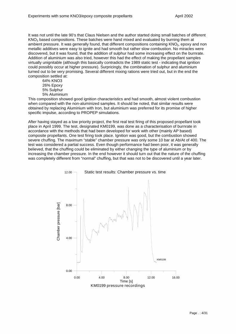
After having stayed as a low priority project, the first real test firing of this proposed propellant tookplace in April 1999. The test, designated KM0199, was done as a characterisation of burnrate inaccordance with the methods that had been developed for work with other (mainly AP based)composite propellants. One test firing took place. Ignition was good, but the combustion showedsevere chuffing. The maximum “stable” chamber pressure was only some 10 bar at Ab/At of 400. Thetest was considered a partial success. Even though performance had been poor, it was generallybelieved, that the chuffing could be eliminated by either changing the type of aluminium or byincreasing the chamber pressure. In the end however it should turn out that the nature of the chuffingwas completely different from “normal” chuffing, but that was not to be discovered until a year later.
0.00 4.00 8.00 12.00 16.00Time [s]
0.00
4.00
8.00
12.00
Cha
mbe
rpre
ssur
e[b
ar]
Static test results: Chamber pressure vs. time
KM0199
KM0199 pressure recordings
Experiments with some KNO3/epoxy composite propellants April 2002
Page . : 5/31
Propellant burnrate testing
This chapter describes the method that DARK uses for characterisation of composite propellants.
Characterisation of a propellant is done by firing a grain of the desired composition in acharacterisation motor while monitoring the chamber pressure and thrust produced during the burn.
The characterisation motor is a small and robust all steel rocket motor designed to withstand highpressures and high temperatures. It has a sortiment of nozzles for operation at a large span of Knvalues – the practically achievable range is in the order of 100 up to 1500. The characterisation motoris intended for determination of purely propellant specific data such as burnrate at different operatingconditions and of the characteristic velocity c*. Generally, the characterisation tests are done withnozzles that have no divergent part, causing severe under expansion. Hence, the measured thrustdata are of limited use and does not lead to any realistic values of specific impulse for the propellant inquestion. Realistic values of Isp may be calculated from thermodynamic data from theoreticalconsiderations, computer simulations or by fitting data from other tests.
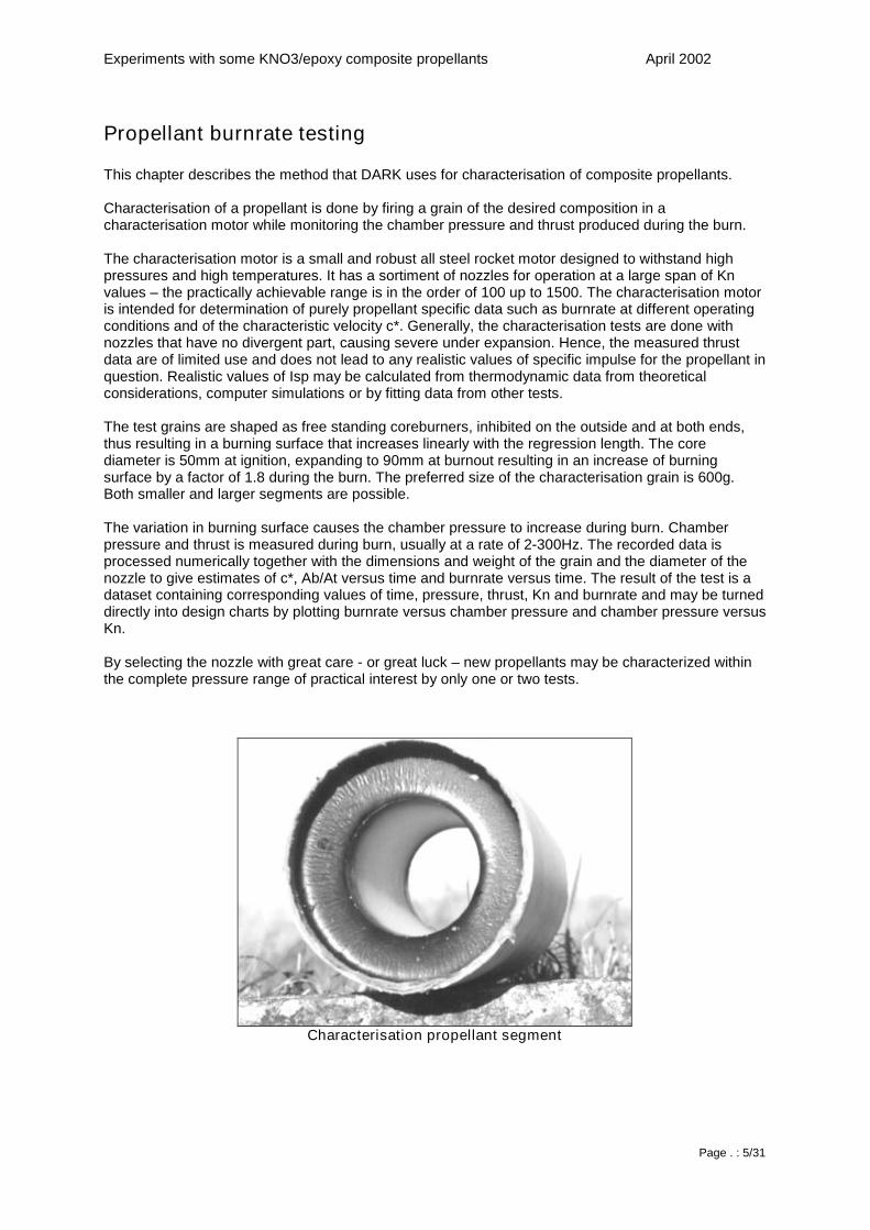
The test grains are shaped as free standing coreburners, inhibited on the outside and at both ends,thus resulting in a burning surface that increases linearly with the regression length. The corediameter is 50mm at ignition, expanding to 90mm at burnout resulting in an increase of burningsurface by a factor of 1.8 during the burn. The preferred size of the characterisation grain is 600g.Both smaller and larger segments are possible.
The variation in burning surface causes the chamber pressure to increase during burn. Chamberpressure and thrust is measured during burn, usually at a rate of 2-300Hz. The recorded data isprocessed numerically together with the dimensions and weight of the grain and the diameter of thenozzle to give estimates of c*, Ab/At versus time and burnrate versus time. The result of the test is adataset containing corresponding values of time, pressure, thrust, Kn and burnrate and may be turneddirectly into design charts by plotting burnrate versus chamber pressure and chamber pressure versusKn.
By selecting the nozzle with great care - or great luck – new propellants may be characterized withinthe complete pressure range of practical interest by only one or two tests.
Characterisation propellant segment
Experiments with some KNO3/epoxy composite propellants April 2002
Page . : 6/31
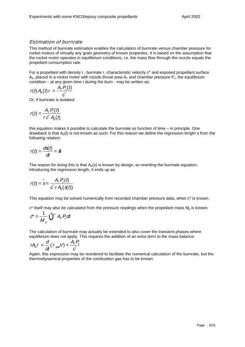
Estimation of burnrateThis method of burnrate estimation enables the calculation of burnrate versus chamber pressure forrocket motors of virtually any grain geometry of known properties. It is based on the assumption thatthe rocket motor operates in equilibrium conditions, i.e. the mass flow through the nozzle equals thepropellant consumption rate.
For a propellant with density ρ, burnrate r, characteristic velocity c* and exposed propellant surfaceAb, placed in a rocket motor with nozzle throat area AT and chamber pressure Pc, the equilibriumcondition – at any given time t during the burn - may be written as:
∗=c
tPAtAtr cT
b)(
)()( ρ
Or, if burnrate is isolated:
)()(
)(tActPA
trb
cT∗=
ρ
this equation makes it possible to calculate the burnrate as function of time – in principle. Onedrawback is that Ab(t) is not known as such. For this reason we define the regression length s from thefollowing relation:
sdt
tdstr &==)(
)(
The reason for doing this is that Ab(s) is known by design, so rewriting the burnrate equation,introducing the regression length, it ends up as:
))(()(
)(tsAc
tPAstr
b
cT
ρ∗
•
==
This equation may be solved numerically from recorded chamber pressure data, when c* is known.
c* itself may also be calculated from the pressure readings when the propellant mass Mp is known:
∫= burnt
cTp
dtPAM
c0
1*
The calculation of burnrate may actually be extended to also cover the transient phases whereequilibrium does not apply. This requires the addition of an extra term to the mass balance:
*)(c
PAVdtdrA cT
gasb += ρρ
Again, this expression may be reordered to facilitate the numerical calculation of the burnrate, but thethermodynamical properties of the combustion gas has to be known.
Experiments with some KNO3/epoxy composite propellants April 2002
Page . : 7/31
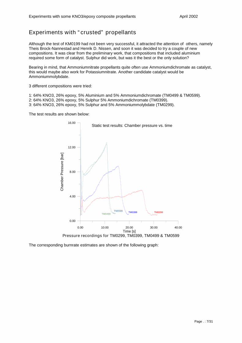
Experiments with “ crusted” propellants
Although the test of KM0199 had not been very successful, it attracted the attention of others, namelyTheis Brock-Nannestad and Henrik D. Nissen, and soon it was decided to try a couple of newcompositions. It was clear from the preliminary work, that compositions that included aluminiumrequired some form of catalyst. Sulphur did work, but was it the best or the only solution?
Bearing in mind, that Ammoniumnitrate propellants quite often use Ammoniumdichromate as catalyst,this would maybe also work for Potassiumnitrate. Another candidate catalyst would beAmmoniummolybdate.
3 different compositions were tried:
1: 64% KNO3, 26% epoxy, 5% Aluminium and 5% Ammoniumdichromate (TM0499 & TM0599).2: 64% KNO3, 26% epoxy, 5% Sulphur 5% Ammoniumdichromate (TM0399).3: 64% KNO3, 26% epoxy, 5% Sulphur and 5% Ammoniummolybdate (TM0299).
The test results are shown below:
0.00 10.00 20.00 30.00 40.00Time [s]
0.00
4.00
8.00
12.00
16.00
Cha
mbe
rPre
ssur
e[b
ar]
TM0299TM0399TM0499
TM0599
Static test results: Chamber pressure vs. time
Pressure recordings for TM0299, TM0399, TM0499 & TM0599
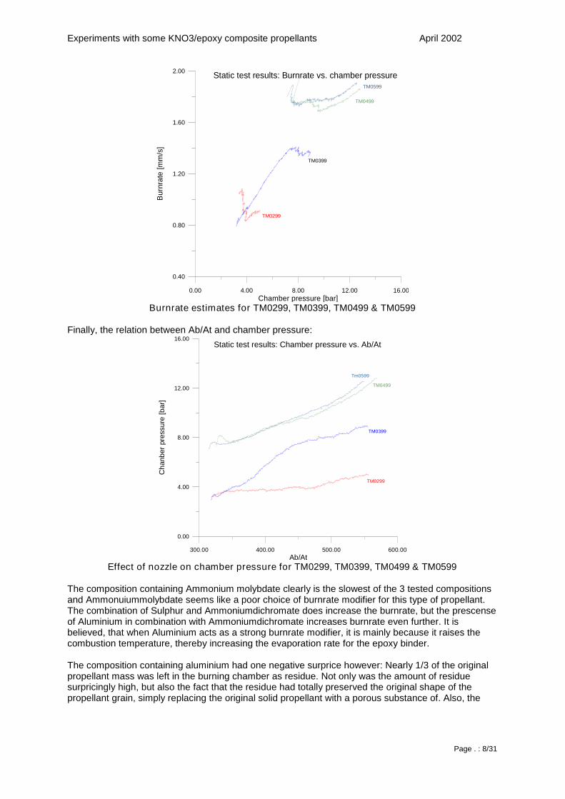
The corresponding burnrate estimates are shown of the following graph:
Experiments with some KNO3/epoxy composite propellants April 2002
Page . : 8/31
0.00 4.00 8.00 12.00 16.00Chamber pressure [bar]
0.40
0.80
1.20
1.60
2.00
Bur
nrat
e[m
m/s
]
Static test results: Burnrate vs. chamber pressure
TM0299
TM0399
TM0499
TM0599
Burnrate estimates for TM0299, TM0399, TM0499 & TM0599
Finally, the relation between Ab/At and chamber pressure:
300.00 400.00 500.00 600.00Ab/At
0.00
4.00
8.00
12.00
16.00
Cha
nber
pres
sure
[bar
]
TM0299
TM0399
TM0499
Tm0599
Static test results: Chamber pressure vs. Ab/At
Effect of nozzle on chamber pressure for TM0299, TM0399, TM0499 & TM0599
The composition containing Ammonium molybdate clearly is the slowest of the 3 tested compositionsand Ammonuiummolybdate seems like a poor choice of burnrate modifier for this type of propellant.The combination of Sulphur and Ammoniumdichromate does increase the burnrate, but the prescenseof Aluminium in combination with Ammoniumdichromate increases burnrate even further. It isbelieved, that when Aluminium acts as a strong burnrate modifier, it is mainly because it raises thecombustion temperature, thereby increasing the evaporation rate for the epoxy binder.
The composition containing aluminium had one negative surprice however: Nearly 1/3 of the originalpropellant mass was left in the burning chamber as residue. Not only was the amount of residuesurpricingly high, but also the fact that the residue had totally preserved the original shape of thepropellant grain, simply replacing the original solid propellant with a porous substance of. Also, the
Experiments with some KNO3/epoxy composite propellants April 2002
Page . : 9/31
residue had the unfortunate characteristic of trapping a significant amount of heat - in fact, theresidue was able to sustain the evaporation and external combustion of coating and liner materials formore than one minute.
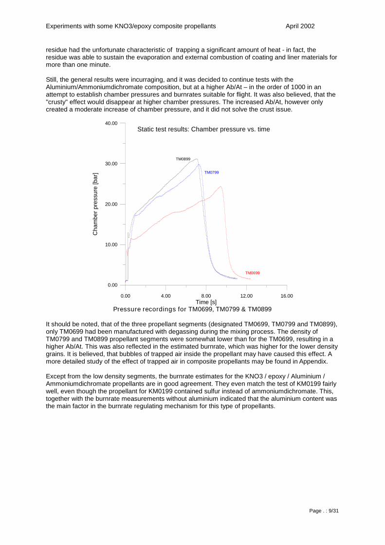
Still, the general results were incurraging, and it was decided to continue tests with theAluminium/Ammoniumdichromate composition, but at a higher Ab/At – in the order of 1000 in anattempt to establish chamber pressures and burnrates suitable for flight. It was also believed, that the"crusty" effect would disappear at higher chamber pressures. The increased Ab/At, however onlycreated a moderate increase of chamber pressure, and it did not solve the crust issue.
0.00 4.00 8.00 12.00 16.00Time [s]
0.00
10.00
20.00
30.00
40.00
Cha
mbe
rpre
ssur
e[b
ar]
TM0699
TM0799
TM0899
Static test results: Chamber pressure vs. time
Pressure recordings for TM0699, TM0799 & TM0899
It should be noted, that of the three propellant segments (designated TM0699, TM0799 and TM0899),only TM0699 had been manufactured with degassing during the mixing process. The density ofTM0799 and TM0899 propellant segments were somewhat lower than for the TM0699, resulting in ahigher Ab/At. This was also reflected in the estimated burnrate, which was higher for the lower densitygrains. It is believed, that bubbles of trapped air inside the propellant may have caused this effect. Amore detailed study of the effect of trapped air in composite propellants may be found in Appendix.
Except from the low density segments, the burnrate estimates for the KNO3 / epoxy / Aluminium /Ammoniumdichromate propellants are in good agreement. They even match the test of KM0199 fairlywell, even though the propellant for KM0199 contained sulfur instead of ammoniumdichromate. This,together with the burnrate measurements without aluminium indicated that the aluminium content wasthe main factor in the burnrate regulating mechanism for this type of propellants.
Experiments with some KNO3/epoxy composite propellants April 2002
Page . : 10/31
0.00 10.00 20.00 30.00 40.00Chamber pressure [bar]
1.60
2.00
2.40
2.80
3.20
Bur
nrat
e[m
m/s
]
TM0699
TM0799
TM0899
Static test results: Burnrate vs. chamber pressure
TM0499
TM0599
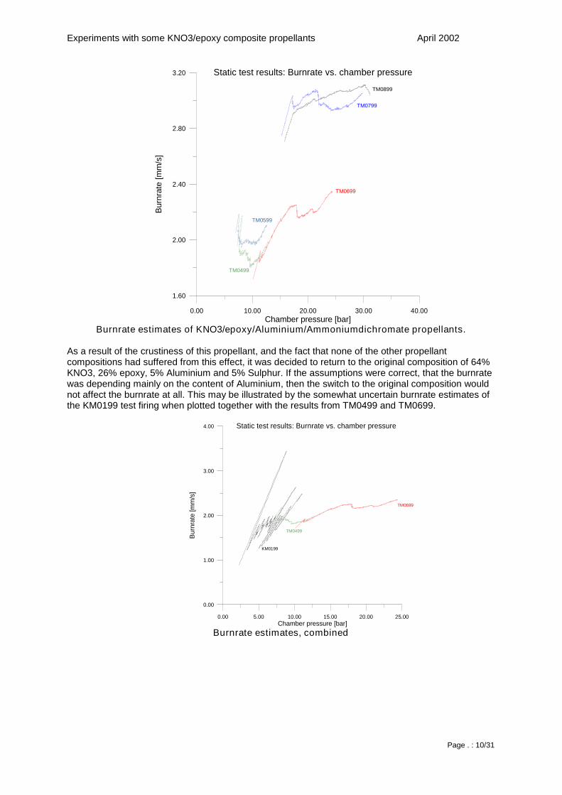
Burnrate estimates of KNO3/epoxy/Aluminium/Ammoniumdichromate propellants.
As a result of the crustiness of this propellant, and the fact that none of the other propellantcompositions had suffered from this effect, it was decided to return to the original composition of 64%KNO3, 26% epoxy, 5% Aluminium and 5% Sulphur. If the assumptions were correct, that the burnratewas depending mainly on the content of Aluminium, then the switch to the original composition wouldnot affect the burnrate at all. This may be illustrated by the somewhat uncertain burnrate estimates ofthe KM0199 test firing when plotted together with the results from TM0499 and TM0699.
0.00 5.00 10.00 15.00 20.00 25.00Chamber pressure [bar]
0.00
1.00
2.00
3.00
4.00
Bur
nrat
e[m
m/s
]
TM0699
Static test results: Burnrate vs. chamber pressure
TM0499
KM0199
Burnrate estimates, combined
Experiments with some KNO3/epoxy composite propellants April 2002
Page . : 11/31
200.00 400.00 600.00 800.00 1000.00Ab/At
0.00
5.00
10.00
15.00
20.00
25.00
Cha
mbe
rpre
ssur
e[b
ar]
TM0699
Static test results: Chamber pressure vs. Ab/At
TM0499
KM0199
Effect of nozzle on chamber pressure, combined
The combined results of TM0499 and TM0699 was turned into a burnrate model assuming thefollowing relationship between pressure and burnrate:
log(r) = a + n*log(Pc) + n2*log(Pc)2+ n3*log(Pc)
3+ n4*log(Pc)4
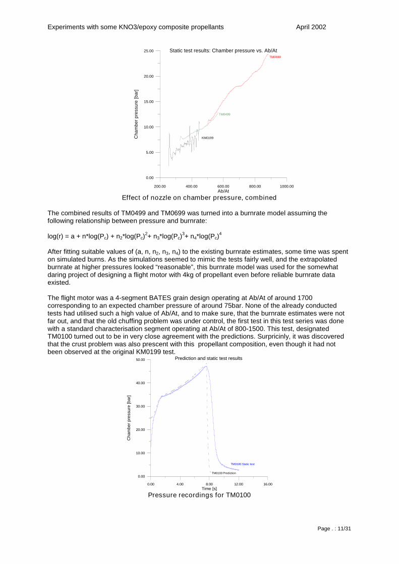
After fitting suitable values of (a, n, n2, n3, n4) to the existing burnrate estimates, some time was spenton simulated burns. As the simulations seemed to mimic the tests fairly well, and the extrapolatedburnrate at higher pressures looked “reasonable”, this burnrate model was used for the somewhatdaring project of designing a flight motor with 4kg of propellant even before reliable burnrate dataexisted.
The flight motor was a 4-segment BATES grain design operating at Ab/At of around 1700corresponding to an expected chamber pressure of around 75bar. None of the already conductedtests had utilised such a high value of Ab/At, and to make sure, that the burnrate estimates were notfar out, and that the old chuffing problem was under control, the first test in this test series was donewith a standard characterisation segment operating at Ab/At of 800-1500. This test, designatedTM0100 turned out to be in very close agreement with the predictions. Surpricinly, it was discoveredthat the crust problem was also prescent with this propellant composition, even though it had notbeen observed at the original KM0199 test.
0.00 4.00 8.00 12.00 16.00Time [s]
0.00
10.00
20.00
30.00
40.00
50.00
Cha
mbe
rpre
ssur
e[b
ar]
Prediction and static test results
TM0100 Static test
TM0100 Prediction
Pressure recordings for TM0100
Experiments with some KNO3/epoxy composite propellants April 2002
Page . : 12/31
TM0100 was followed by an apparently successful test of a single segment BATES grain motor.Unfortuneatly however, all data recordings from this test were lost due to a communication error.
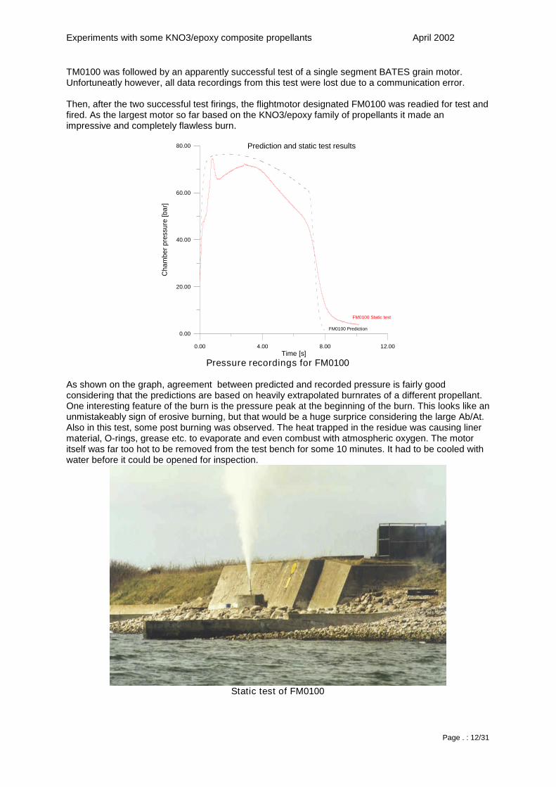
Then, after the two successful test firings, the flightmotor designated FM0100 was readied for test andfired. As the largest motor so far based on the KNO3/epoxy family of propellants it made animpressive and completely flawless burn.
0.00 4.00 8.00 12.00Time [s]
0.00
20.00
40.00
60.00
80.00
Cha
mbe
rpre
ssur
e[b
ar]
FM0100 Static test
FM0100 Prediction
Prediction and static test results
Pressure recordings for FM0100
As shown on the graph, agreement between predicted and recorded pressure is fairly goodconsidering that the predictions are based on heavily extrapolated burnrates of a different propellant.One interesting feature of the burn is the pressure peak at the beginning of the burn. This looks like anunmistakeably sign of erosive burning, but that would be a huge surprice considering the large Ab/At.Also in this test, some post burning was observed. The heat trapped in the residue was causing linermaterial, O-rings, grease etc. to evaporate and even combust with atmospheric oxygen. The motoritself was far too hot to be removed from the test bench for some 10 minutes. It had to be cooled withwater before it could be opened for inspection.
Static test of FM0100
Experiments with some KNO3/epoxy composite propellants April 2002
Page . : 13/31
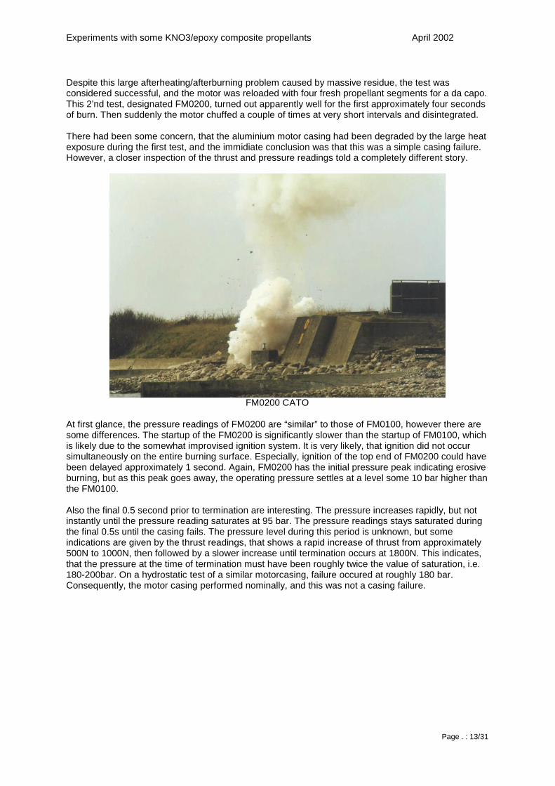
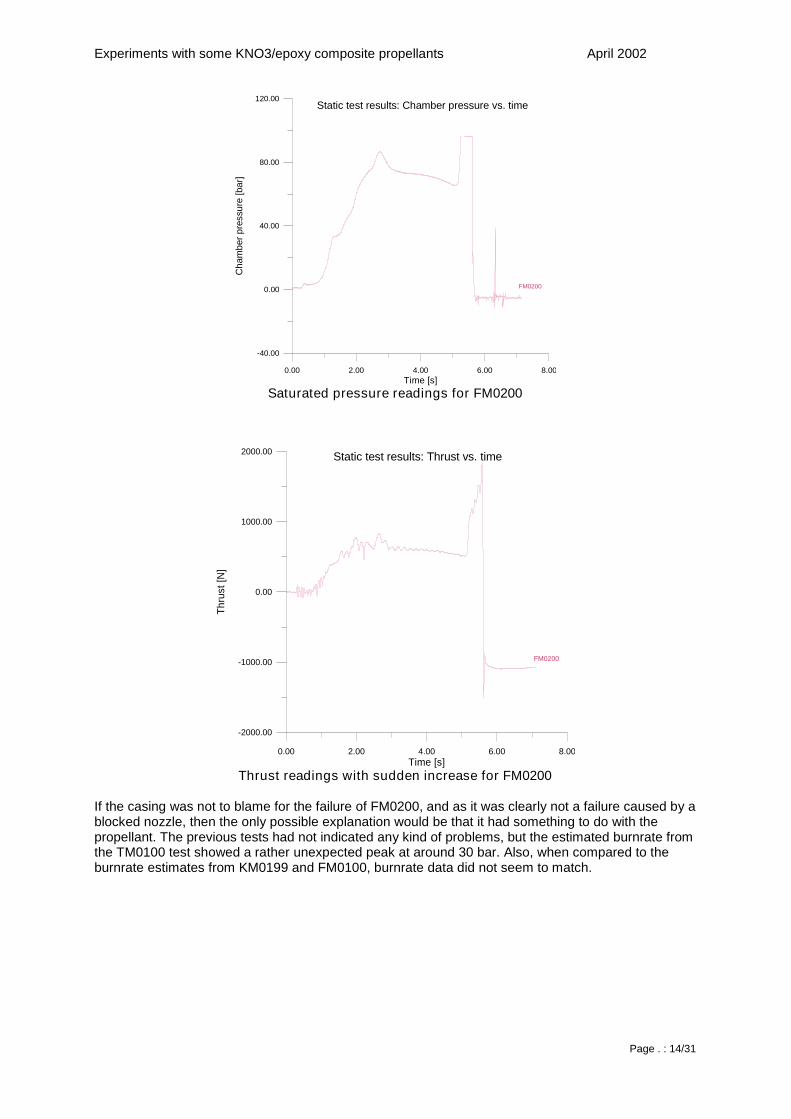
Despite this large afterheating/afterburning problem caused by massive residue, the test wasconsidered successful, and the motor was reloaded with four fresh propellant segments for a da capo.This 2’nd test, designated FM0200, turned out apparently well for the first approximately four secondsof burn. Then suddenly the motor chuffed a couple of times at very short intervals and disintegrated.
There had been some concern, that the aluminium motor casing had been degraded by the large heatexposure during the first test, and the immidiate conclusion was that this was a simple casing failure.However, a closer inspection of the thrust and pressure readings told a completely different story.
FM0200 CATO
At first glance, the pressure readings of FM0200 are “similar” to those of FM0100, however there aresome differences. The startup of the FM0200 is significantly slower than the startup of FM0100, whichis likely due to the somewhat improvised ignition system. It is very likely, that ignition did not occursimultaneously on the entire burning surface. Especially, ignition of the top end of FM0200 could havebeen delayed approximately 1 second. Again, FM0200 has the initial pressure peak indicating erosiveburning, but as this peak goes away, the operating pressure settles at a level some 10 bar higher thanthe FM0100.
Also the final 0.5 second prior to termination are interesting. The pressure increases rapidly, but notinstantly until the pressure reading saturates at 95 bar. The pressure readings stays saturated duringthe final 0.5s until the casing fails. The pressure level during this period is unknown, but someindications are given by the thrust readings, that shows a rapid increase of thrust from approximately500N to 1000N, then followed by a slower increase until termination occurs at 1800N. This indicates,that the pressure at the time of termination must have been roughly twice the value of saturation, i.e.180-200bar. On a hydrostatic test of a similar motorcasing, failure occured at roughly 180 bar.Consequently, the motor casing performed nominally, and this was not a casing failure.
Experiments with some KNO3/epoxy composite propellants April 2002
Page . : 14/31
0.00 2.00 4.00 6.00 8.00Time [s]
-40.00
0.00
40.00
80.00
120.00
Cha
mbe
rpre
ssur
e[b
ar]
Static test results: Chamber pressure vs. time
FM0200
Saturated pressure readings for FM0200
0.00 2.00 4.00 6.00 8.00Time [s]
-2000.00
-1000.00
0.00
1000.00
2000.00
Thru
st[N
]
Static test results: Thrust vs. time
FM0200
Thrust readings with sudden increase for FM0200
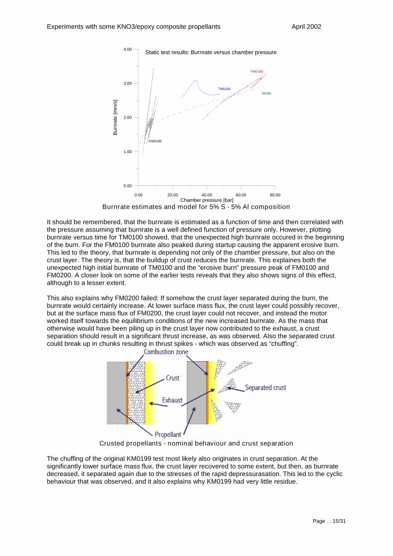
If the casing was not to blame for the failure of FM0200, and as it was clearly not a failure caused by ablocked nozzle, then the only possible explanation would be that it had something to do with thepropellant. The previous tests had not indicated any kind of problems, but the estimated burnrate fromthe TM0100 test showed a rather unexpected peak at around 30 bar. Also, when compared to theburnrate estimates from KM0199 and FM0100, burnrate data did not seem to match.
Experiments with some KNO3/epoxy composite propellants April 2002
Page . : 15/31
0.00 20.00 40.00 60.00 80.00Chamber pressure [bar]
0.00
1.00
2.00
3.00
4.00
Bur
nrat
e[m
m/s
]
FM0100
KM0199
TM0100Model
Static test results: Burnrate versus chamber pressure
Burnrate estimates and model for 5% S - 5% Al composition
It should be remembered, that the burnrate is estimated as a function of time and then correlated withthe pressure assuming that burnrate is a well defined function of pressure only. However, plottingburnrate versus time for TM0100 showed, that the unexpected high burnrate occured in the beginningof the burn. For the FM0100 burnrate also peaked during startup causing the apparent erosive burn.This led to the theory, that burnrate is depending not only of the chamber pressure, but also on thecrust layer. The theory is, that the buildup of crust reduces the burnrate. This explaines both theunexpected high initial burnrate of TM0100 and the “erosive burn” pressure peak of FM0100 andFM0200. A closer look on some of the earlier tests reveals that they also shows signs of this effect,although to a lesser extent.
This also explains why FM0200 failed: If somehow the crust layer separated during the burn, theburnrate would certainly increase. At lower surface mass flux, the crust layer could possibly recover,but at the surface mass flux of FM0200, the crust layer could not recover, and instead the motorworked itself towards the equilibrium conditions of the new increased burnrate. As the mass thatotherwise would have been piling up in the crust layer now contributed to the exhaust, a crustseparation should result in a significant thrust increase, as was observed. Also the separated crustcould break up in chunks resulting in thrust spikes - which was observed as “chuffing”.
Crusted propellants - nominal behaviour and crust separation
The chuffing of the original KM0199 test most likely also originates in crust separation. At thesignificantly lower surface mass flux, the crust layer recovered to some extent, but then, as burnratedecreased, it separated again due to the stresses of the rapid depressurasation. This led to the cyclicbehaviour that was observed, and it also explains why KM0199 had very little residue.
Experiments with some KNO3/epoxy composite propellants April 2002
Page . : 16/31
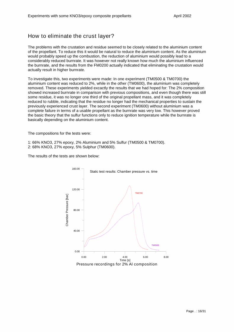
How to eliminate the crust layer?
The problems with the crustation and residue seemed to be closely related to the aluminium contentof the propellant. To reduce this it would be natural to reduce the aluminium content. As the aluminiumwould probably speed up the combustion, the reduction of aluminium would possibly lead to aconsiderably reduced burnrate. It was however not really known how much the aluminium influencedthe burnrate, and the results from the FM0200 actually indicated that eliminating the crustation wouldactually result in higher burnrate.
To investigate this, two experiments were made: In one experiment (TM0500 & TM0700) thealuminium content was reduced to 2%, while in the other (TM0600), the aluminium was completelyremoved. These experiments yielded excactly the results that we had hoped for: The 2% compositionshowed increased burnrate in comparison with previous compositions, and even though there was stillsome residue, it was no longer one third of the original propellant mass, and it was completelyreduced to rubble, indicating that the residue no longer had the mechanical properties to sustain thepreviously experienced crust layer. The second experiment (TM0600) without aluminium was acomplete failure in terms of a usable propellant as the burnrate was very low. This however provedthe basic theory that the sulfur functions only to reduce ignition temperature while the burnrate isbasically depending on the aluminium content.
The compositions for the tests were:
1: 66% KNO3, 27% epoxy, 2% Aluminium and 5% Sulfur (TM0500 & TM0700).2: 68% KNO3, 27% epoxy, 5% Sulphur (TM0600).
The results of the tests are shown below:
0.00 2.00 4.00 6.00 8.00Time [s]
0.00
40.00
80.00
120.00
160.00
Cha
mbe
rPre
ssur
e[b
ar]
TM0500
TM0700
Static test results: Chamber pressure vs. time
Pressure recordings for 2% Al composition
Experiments with some KNO3/epoxy composite propellants April 2002
Page . : 17/31
0.00 40.00 80.00 120.00 160.00Chamber pressure [bar]
0.00
2.00
4.00
6.00
8.00
Bur
nrat
e[m
m/s
]
Static test results: Burnrate vs. chamber pressure
TM0500
TM0700
Burnrate estimates for 2% Al composition
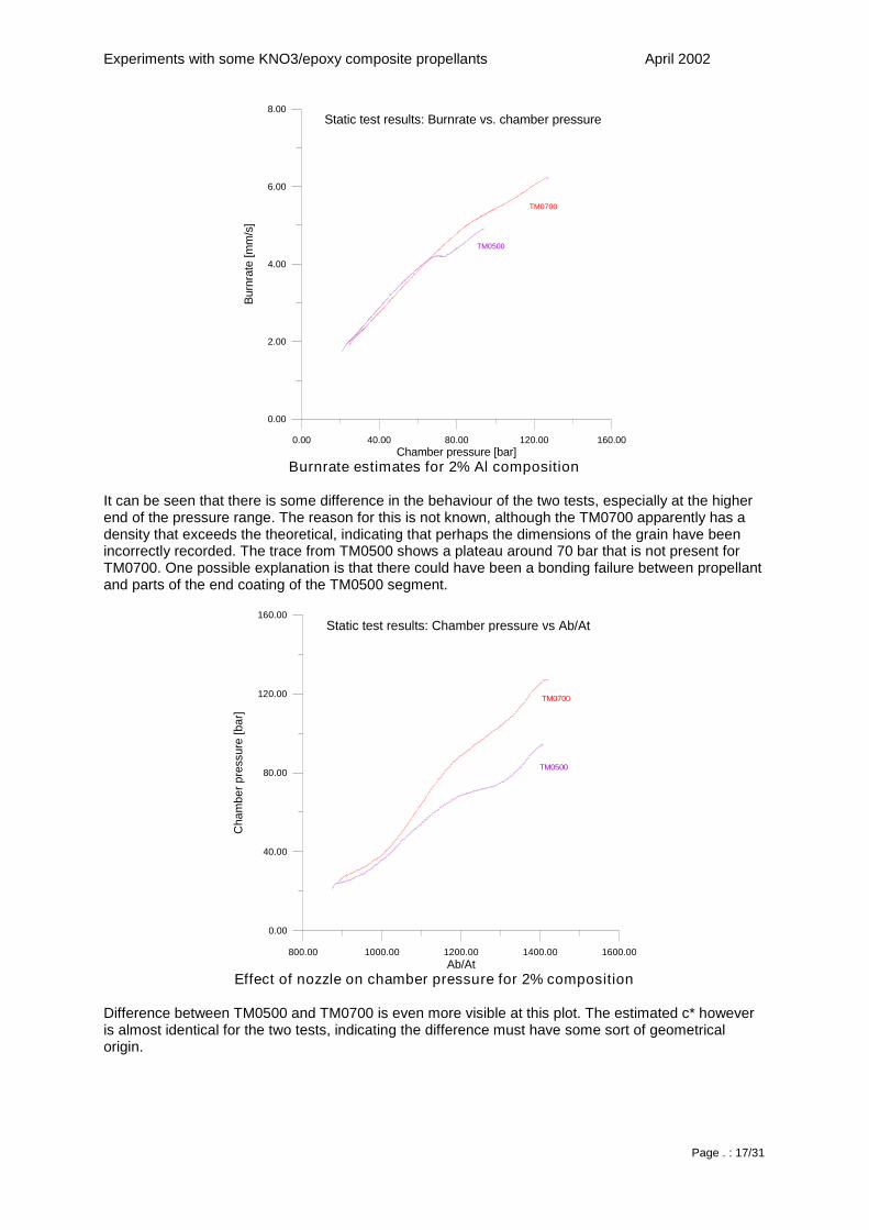
It can be seen that there is some difference in the behaviour of the two tests, especially at the higherend of the pressure range. The reason for this is not known, although the TM0700 apparently has adensity that exceeds the theoretical, indicating that perhaps the dimensions of the grain have beenincorrectly recorded. The trace from TM0500 shows a plateau around 70 bar that is not present forTM0700. One possible explanation is that there could have been a bonding failure between propellantand parts of the end coating of the TM0500 segment.
800.00 1000.00 1200.00 1400.00 1600.00Ab/At
0.00
40.00
80.00
120.00
160.00
Cha
mbe
rpre
ssur
e[b
ar]
Static test results: Chamber pressure vs Ab/At
TM0700
TM0500
Effect of nozzle on chamber pressure for 2% composition
Difference between TM0500 and TM0700 is even more visible at this plot. The estimated c* howeveris almost identical for the two tests, indicating the difference must have some sort of geometricalorigin.
Experiments with some KNO3/epoxy composite propellants April 2002
Page . : 18/31
0.00 10.00 20.00 30.00Time [s]
0.00
4.00
8.00
12.00
16.00
Cha
mbe
rPre
ssur
e[b
ar]
TM0600
Static test results: Chamber pressure vs. time
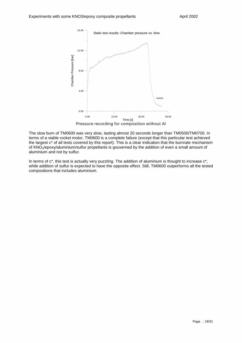
Pressure recording for composition without Al
The slow burn of TM0600 was very slow, lasting almost 20 seconds longer than TM0500/TM0700. Interms of a viable rocket motor, TM0600 is a complete failure (except that this particular test achievedthe largest c* of all tests covered by this report). This is a clear indication that the burnrate mechanismof KNO3/epoxy/aluminium/sulfur propellants is gouverned by the addition of even a small amount ofaluminium and not by sulfur.
In terms of c*, this test is actually very puzzling. The addition of aluminium is thought to increase c*,while addition of sulfur is expected to have the opposite effect. Still, TM0600 outperforms all the testedcompositions that includes aluminium.
Experiments with some KNO3/epoxy composite propellants April 2002
Page . : 19/31
Conclusion on “ crusted” propellants
Several compositions of KNO3/epoxy propellants has been tested. In general, the compositionswithout aluminium were fairly easy to ignite, but had too low burnrates for any practical rocketry use.The compositions containing aluminium had much improved burnrate, but required the addition of asensitizer to aid the ignition process. Compositions with aluminium and no sensitizer turned out to bevery hard to ignite, at least at ambient pressure, but this may depend on the particle size of thealuminium powder.
Propellant compositions containing aluminium combined with either Sulphur or Ammoniumdichromateshows improved burnrate when compared to compositions without aluminium. The resulting burnrateseems to improve dramatically by the prescense of even small quantities of aluminium.
Some of the tested propellant compositions tends to create a “crust” of residue. This has beenobserved only with the propellants containing aluminium. The crusted propellants does exhibitburnrate characteristics that are in general reproducible, and depends on both chamber pressure andthe thickness of the crust layer. The crust layer seems to reduce the burnrate drastically. Also, thecrust layer traps the solid combustion products within the motor, thus lowering the performance of themotor both in terms of mass ratio and c*, at the same time increasing the thermal exposure of themotor casing. The crust layer has been observed to separate in some cases, for reasons that are notfully understood. As such a separation will cause the burnrate to increase, it will result in eitherchuffing or plain CATO. This makes the crusted types of propellants unsuitable for rocket motorpropellants.
The crusting may be avoided by keeping the aluminium content low. Successful tests has beenachieved with aluminium contents of 2% for which the crust layer did not occur while the aluminiumcontent was still sufficient to achieve a decent burnrate of more than 4mm/s at 68 bar (1000psi). Thiscomposition, which was used for TM0500 and TM0700 is considered to be an acceptable result of thisinvestigation and seems to be promising in terms of amateur rocketry propulsion for its of low cost andeasy manufacture and storage. There is still room for continued experimentation though, as theachieved c* does not live up to the expectations.
It should be noted, that in strand burner tests conducted by Richard Nakka, KNO3/epoxy propellantsamples with varying amounts of aluminium has been tested. Those propellant samples relied on ironoxide (Fe2O3) instead of sulfur to reduce ignition temperature and/or increase burnrate. Also in thesetests crustation occured in some cases.
Measurements of burnrate versus pressure has been made for a composition of67% KNO38% Aluminum1% Iron oxide (Fe2O3)24% EpoxyThe resulting burnrates are somewhat higher than those found in the previous chapter forcompositions with 2% aluminium - this is a further indication of the significance of aluminium asburnrate modifier for these types of propellant.
Experiments with some KNO3/epoxy composite propellants April 2002
Page . : 20/31
30.00 40.00 50.00 60.00 70.00 80.00Chamber Pressure (bar)
3.00
4.00
5.00
6.00
7.00
8.00
Bur
nrat
e(m
m/s
)
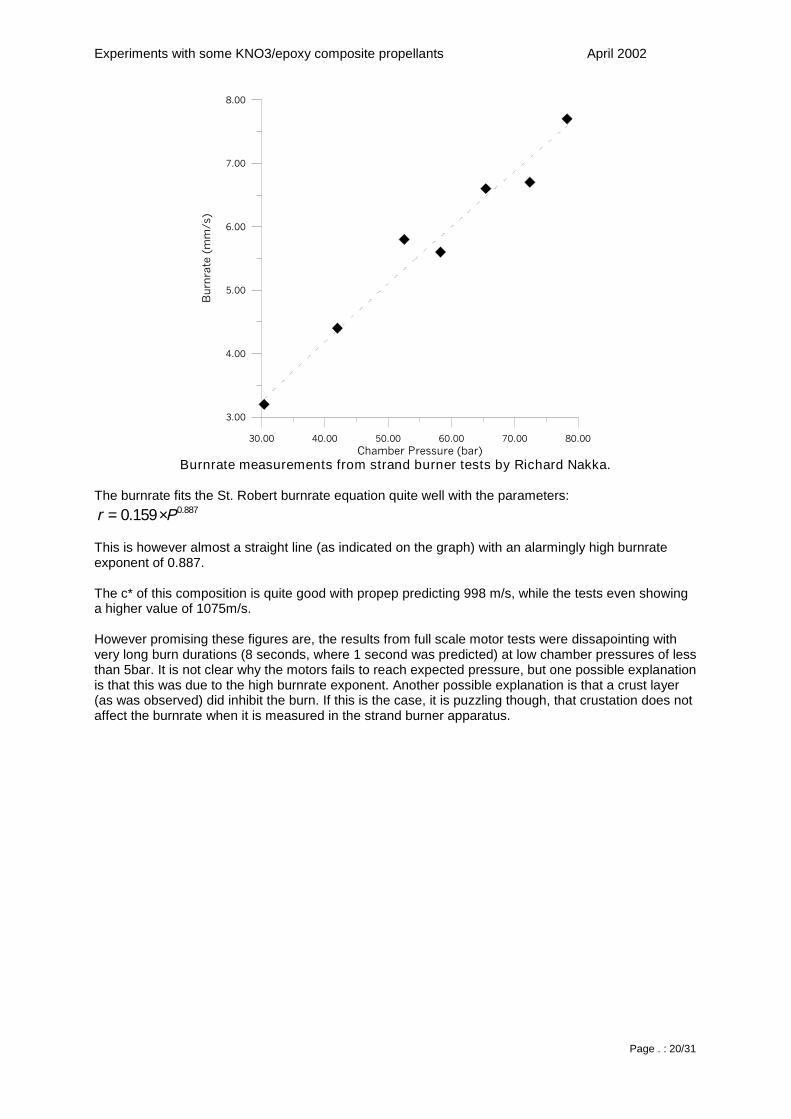
Burnrate measurements from strand burner tests by Richard Nakka.
The burnrate fits the St. Robert burnrate equation quite well with the parameters:887.0159.0 Pr ⋅=
This is however almost a straight line (as indicated on the graph) with an alarmingly high burnrateexponent of 0.887.
The c* of this composition is quite good with propep predicting 998 m/s, while the tests even showinga higher value of 1075m/s.
However promising these figures are, the results from full scale motor tests were dissapointing withvery long burn durations (8 seconds, where 1 second was predicted) at low chamber pressures of lessthan 5bar. It is not clear why the motors fails to reach expected pressure, but one possible explanationis that this was due to the high burnrate exponent. Another possible explanation is that a crust layer(as was observed) did inhibit the burn. If this is the case, it is puzzling though, that crustation does notaffect the burnrate when it is measured in the strand burner apparatus.
Experiments with some KNO3/epoxy composite propellants April 2002
Page . : 21/31
Performance
Even though the work with KNO3/epoxy propellants mainly has been done to investigate ways toimprove the burnrate so that it reaches a sufficient level for use in rocket motors (a rule of thumb saysthat it has to be at least 4mm/s), the overall performance can not be neglected.
There may be many aspects of "performance" to be considered, but for the practical use for rocketpropellant, four factors are considered of major importance:
• Costs• Ease of manufacturing• Exhaust velocity• Density
The element of costs is basically embedded within the framework of this investigation - There is reallyno need to consider KNO3 based propellants if costs are unimportant. The use of expensive additiveslike ammoniumdichromate may degrade this basic assumption, however some freedom has to remainto give the investigation a chance of leading somewhere.
Ease of manufacturing requires that extreme solids loading is avoided, and that the process shouldnot require exotic equippment or complex workflow. This is reflected in the compositions that arecovered by the experimental work that forms the base for this report.
The properties of density and exhaust velocity are basically independent of the experimental work, butthese are worth some considerations. High propellant densities are considered important because ofthe increased amount of energy that can be stored in a certain volume of space - this is often refferedto as "volume specific impulse". The exhaust velocity governs the velocity increase that a given rocketcan achieve - with "specific impulse" being the crucial figure. It should be noted however, that bothtypes of specific impulse are properties rocket motors - the important figures for rocket propellants arethe density and the characteristic velocity c*.
0.50 0.60 0.70 0.80 0.90Oxydizer fraction
720.00
760.00
800.00
840.00
880.00
920.00
c*(m
/s)
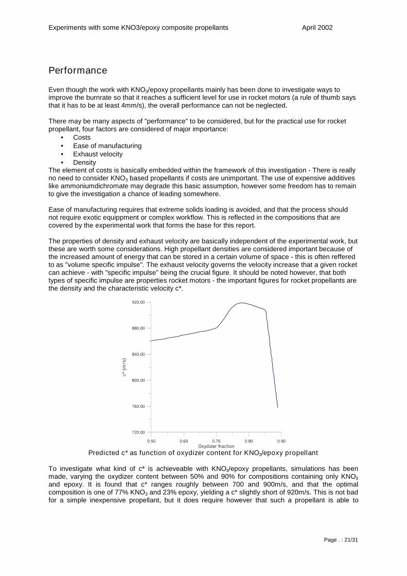
Predicted c* as function of oxydizer content for KNO3/epoxy propellant
To investigate what kind of c* is achieveable with KNO3/epoxy propellants, simulations has beenmade, varying the oxydizer content between 50% and 90% for compositions containing only KNO3and epoxy. It is found that c* ranges roughly between 700 and 900m/s, and that the optimalcomposition is one of 77% KNO3 and 23% epoxy, yielding a c* slightly short of 920m/s. This is not badfor a simple inexpensive propellant, but it does require however that such a propellant is able to
Experiments with some KNO3/epoxy composite propellants April 2002
Page . : 22/31
maintain burnrates within the range of practical use - and this is not supported by any experiment fromthis report.
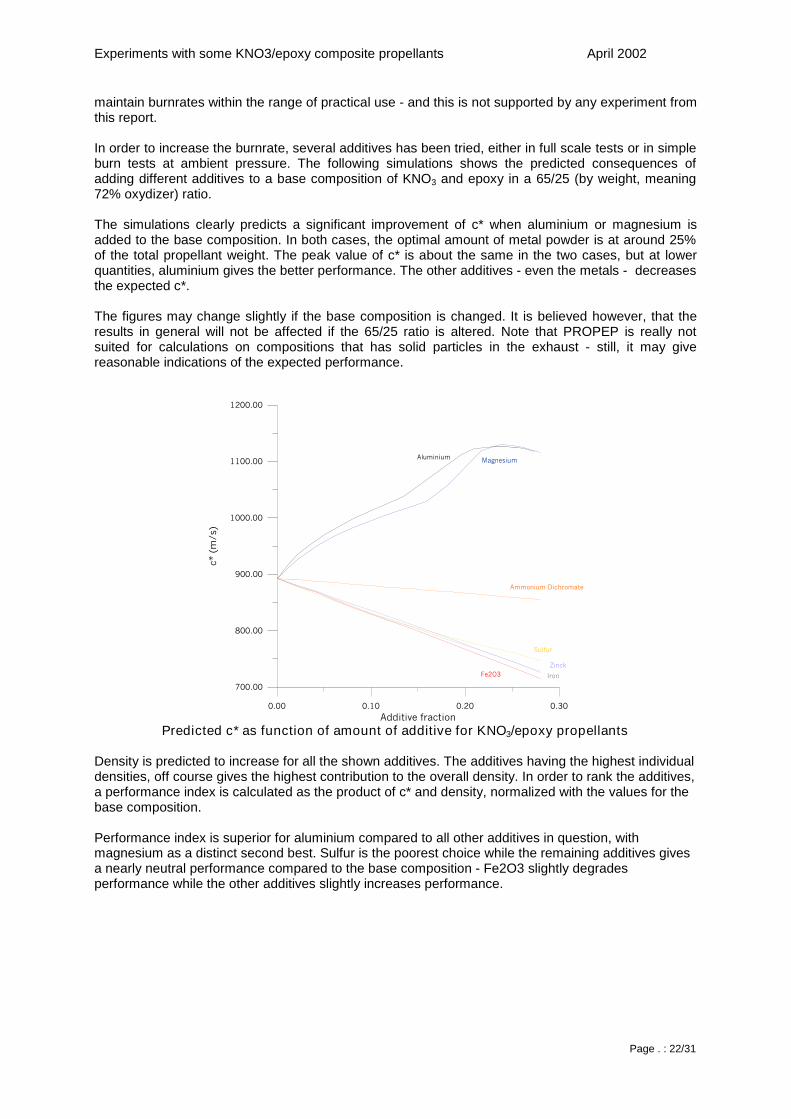
In order to increase the burnrate, several additives has been tried, either in full scale tests or in simpleburn tests at ambient pressure. The following simulations shows the predicted consequences ofadding different additives to a base composition of KNO3 and epoxy in a 65/25 (by weight, meaning72% oxydizer) ratio.
The simulations clearly predicts a significant improvement of c* when aluminium or magnesium isadded to the base composition. In both cases, the optimal amount of metal powder is at around 25%of the total propellant weight. The peak value of c* is about the same in the two cases, but at lowerquantities, aluminium gives the better performance. The other additives - even the metals - decreasesthe expected c*.
The figures may change slightly if the base composition is changed. It is believed however, that theresults in general will not be affected if the 65/25 ratio is altered. Note that PROPEP is really notsuited for calculations on compositions that has solid particles in the exhaust - still, it may givereasonable indications of the expected performance.
0.00 0.10 0.20 0.30Additive fraction
700.00
800.00
900.00
1000.00
1100.00
1200.00
c*(m
/s)
Aluminium
Ammonium Dichromate
IronFe2O3
Magnesium
Sulfur
Zinck
Predicted c* as function of amount of additive for KNO3/epoxy propellants
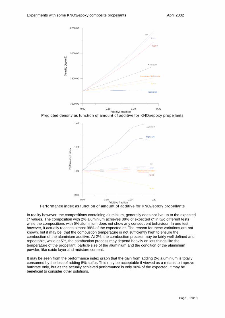
Density is predicted to increase for all the shown additives. The additives having the highest individualdensities, off course gives the highest contribution to the overall density. In order to rank the additives,a performance index is calculated as the product of c* and density, normalized with the values for thebase composition.
Performance index is superior for aluminium compared to all other additives in question, withmagnesium as a distinct second best. Sulfur is the poorest choice while the remaining additives givesa nearly neutral performance compared to the base composition - Fe2O3 slightly degradesperformance while the other additives slightly increases performance.
Experiments with some KNO3/epoxy composite propellants April 2002
Page . : 23/31
0.00 0.10 0.20 0.30Additive fraction
1600.00
1800.00
2000.00
2200.00
Den
sity
(kg/
m3)
Aluminium
Ammonium Dichromate
Iron
Fe2O3
Magnesium
Sulfur
Zinck
Predicted density as function of amount of additive for KNO3/epoxy propellants
0.00 0.10 0.20 0.30Additive fraction
0.80
1.00
1.20
1.40
Per
form
ance
inde
x
Aluminium
Magnesium
Ammonium Dichromate
Fe2O3
Iron
Zinck
Sulfur
Performance index as function of amount of additive for KNO3/epoxy propellants
In reality however, the compositions containing aluminium, generally does not live up to the expectedc* values. The composition with 2% aluminium achieves 89% of expected c* in two different testswhile the compositions with 5% aluminium does not show any consequent behaviour. In one testhowever, it actually reaches almost 99% of the expected c*. The reason for these variations are notknown, but it may be, that the combustion temperature is not sufficiently high to ensure thecombustion of the aluminium additive. At 2%, the combustion process may be fairly well defined andrepeatable, while at 5%, the combustion process may depend heavily on lots things like thetemperature of the propellant, particle size of the aluminium and the condition of the aluminiumpowder, like oxide layer and moisture content.
It may be seen from the performance index graph that the gain from adding 2% aluminium is totallyconsumed by the loss of adding 5% sulfur. This may be acceptable if viewed as a means to improveburnrate only, but as the actually achieved performance is only 90% of the expected, it may bebeneficial to consider other solutions.
Experiments with some KNO3/epoxy composite propellants April 2002
Page . : 24/31
Assuming that aluminium improves the burnrate due to some general properties of metals, any othermetal powder should basically do the same trick (this was also indicated in the introduction, where itwas noted that iron powder seemed to improve burnrate). It still has to be verified, but one canspeculate that if aluminium is replaced by a metal with significantly lower boiling point (i.e. Zn or Mg),combustion will be smoother and higher metal fractions may be achieveable, even without the needfor a sensitizer agent (sulfur).
Magnesium is known to improve performance (both c* and burnrate) for ammonium nitrate propellantsand it is likely to do the same for the KNO3/epoxy compositions covered by this report. Magnesiumpowder is quite expensive however. Zinck powder in small quantities may be a cost effective solutionto boost the burnrate of the base composition to a practical value, at only a slight reduction ofcharacteristic velocity.
One possible reason that aluminum powder improves the burnrate could be that it simply absorbs IRradiation. If this is the case, than a small amount of carbon black would yield significant improvementsin the burnrate. It is known that carbon black in some cases may act as a catalyst, so replacing thealuminium or the sulfur could also be an experiment worth trying.
Experiments with some KNO3/epoxy composite propellants April 2002
Page . : 25/31
Appendix
Effects of trapped air in composite propellants
Trapped air in composite propellants is normally considered unfavourable although it could bebeneficial as burnrate modifier if the amount of trapped air could be controlled.
The main disadvantages of trapped air are decreased propellant density and safety concerns.Decrease of density means that the motorcasing has to be larger (heavier) to hold a specific amountof propellant, causing the total performance of the rocket as a system to drop. For amateur rocketry,this is usually of secondary importance. The primary concern is that trapped air influences on theburning surface of the grain, thus increasing the risc of a CATO. To reduce the amount of trapped air,it is common practice to degas the propellant during mixing. Using this technique, the resultingpropellant density is usually very close to the theoretical, often better than 98%. Mixing withoutdegassing may result in densities between 90 and 95% of the theoretical. In most cases however, thepropellant may still turn out to work reliably. The natural question to ask is then: What is the criticalpropellant density? – The answer to this question depends on various things, including the burnrateexponent of the propellant in question, and it is possible only to get an overview of the effects.
Trapped air may be in three different forms: isolated air bubbles, air channels - “wormholes” andcracks.
Cracks are the results of bad propellant compositions, a poor manufacturing process, wrong storageconditions or plain handling errors. Cracks should not uccur under normal circumstances and will notbe discussed further.
Isolated air bubbles is the most common type of trapped air and may be the result of poor degassing,viscosity problems or of “foaming” of certain types of binders. The effect of isolated air bubbles may beanything from neglegtable to catastrophic.
Wormholes are the result of either insufficient binder of foaming. Wormholes are usually microscopic,and may not be discovered by visual inspection. They do however form a network of channelsthroughout the grain, and when the grain is ignited an pressurised, the hot gases will penetrate thegrain resulting in certain CATO.
Larger air bubbles or cracks may be discovered by inspection, visually or X-ray. Microscopic bubblesor wormholes may require inspection under microscope or dye-bathing. Still, the trapped air takes upvolume, and estimation of actual propellant density is the most obvious way of non destructivedetermination of the amount of trapped air.
The theoretical density of a propellant consisting of N ingredients may be written as:
∑
∑=
N i
i
Ni
thery m
m
ρ
ρ
Where mi is the mass of the i’th ingredient and ρi is the density of the i’th ingredient. The values of mi
is determined by weighing the ingredients during the process of manufacturing the propellant, while ρimay be determined from materials proporties tables or from experiments.
The actual density may be written as
Vm
actual =ρ
Experiments with some KNO3/epoxy composite propellants April 2002
Page . : 26/31
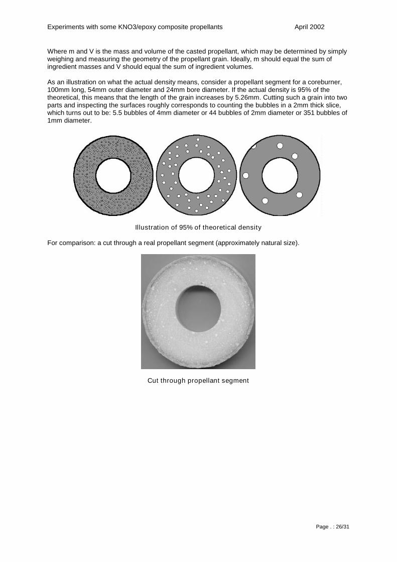
Where m and V is the mass and volume of the casted propellant, which may be determined by simplyweighing and measuring the geometry of the propellant grain. Ideally, m should equal the sum ofingredient masses and V should equal the sum of ingredient volumes.
As an illustration on what the actual density means, consider a propellant segment for a coreburner,100mm long, 54mm outer diameter and 24mm bore diameter. If the actual density is 95% of thetheoretical, this means that the length of the grain increases by 5.26mm. Cutting such a grain into twoparts and inspecting the surfaces roughly corresponds to counting the bubbles in a 2mm thick slice,which turns out to be: 5.5 bubbles of 4mm diameter or 44 bubbles of 2mm diameter or 351 bubbles of1mm diameter.
Illustration of 95% of theoretical density
For comparison: a cut through a real propellant segment (approximately natural size).
Cut through propellant segment
Experiments with some KNO3/epoxy composite propellants April 2002
Page . : 27/31
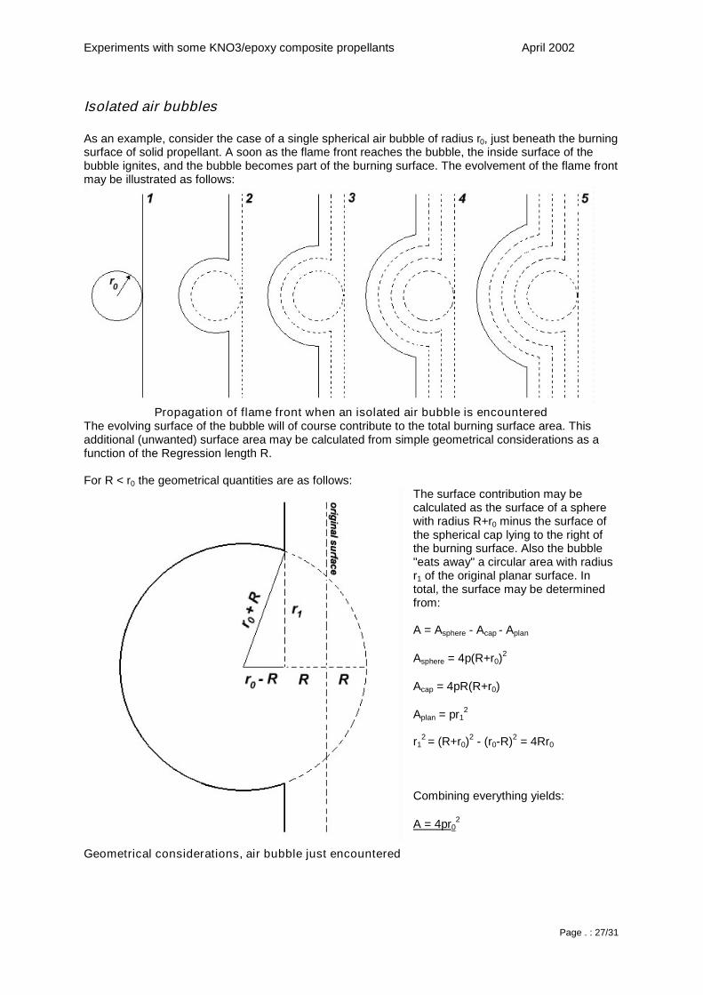
Isolated air bubbles
As an example, consider the case of a single spherical air bubble of radius r0, just beneath the burningsurface of solid propellant. A soon as the flame front reaches the bubble, the inside surface of thebubble ignites, and the bubble becomes part of the burning surface. The evolvement of the flame frontmay be illustrated as follows:
Propagation of flame front when an isolated air bubble is encounteredThe evolving surface of the bubble will of course contribute to the total burning surface area. Thisadditional (unwanted) surface area may be calculated from simple geometrical considerations as afunction of the Regression length R.
For R < r0 the geometrical quantities are as follows:The surface contribution may becalculated as the surface of a spherewith radius R+r0 minus the surface ofthe spherical cap lying to the right ofthe burning surface. Also the bubble"eats away" a circular area with radiusr1 of the original planar surface. Intotal, the surface may be determinedfrom:
A = Asphere - Acap - Aplan
Asphere = 4π(R+r0)2
Acap = 4πR(R+r0)
Aplan = πr12
r12 = (R+r0)
2 - (r0-R)2 = 4Rr0
Combining everything yields:
A = 4πr02
Geometrical considerations, air bubble just encountered
Experiments with some KNO3/epoxy composite propellants April 2002
Page . : 28/31
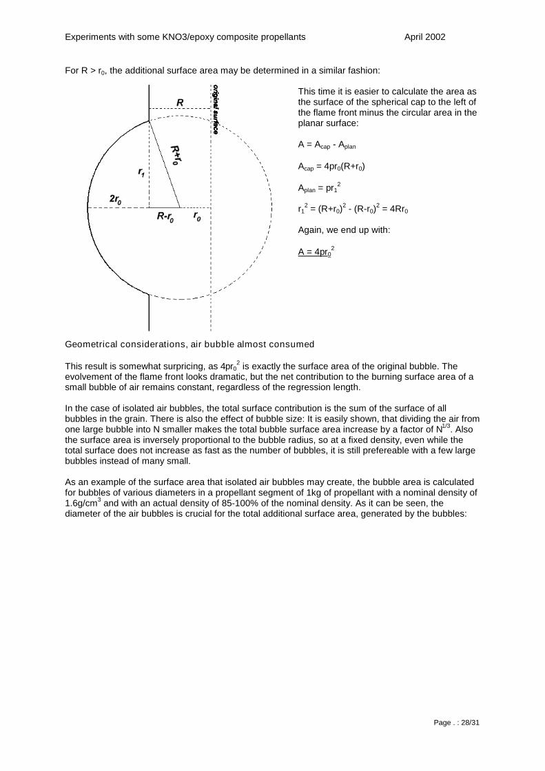
For R > r0, the additional surface area may be determined in a similar fashion:
This time it is easier to calculate the area asthe surface of the spherical cap to the left ofthe flame front minus the circular area in theplanar surface:
A = Acap - Aplan
Acap = 4πr0(R+r0)
Aplan = πr12
r12 = (R+r0)
2 - (R-r0)2 = 4Rr0
Again, we end up with:
A = 4πr02
Geometrical considerations, air bubble almost consumed
This result is somewhat surpricing, as 4πr02 is exactly the surface area of the original bubble. The
evolvement of the flame front looks dramatic, but the net contribution to the burning surface area of asmall bubble of air remains constant, regardless of the regression length.
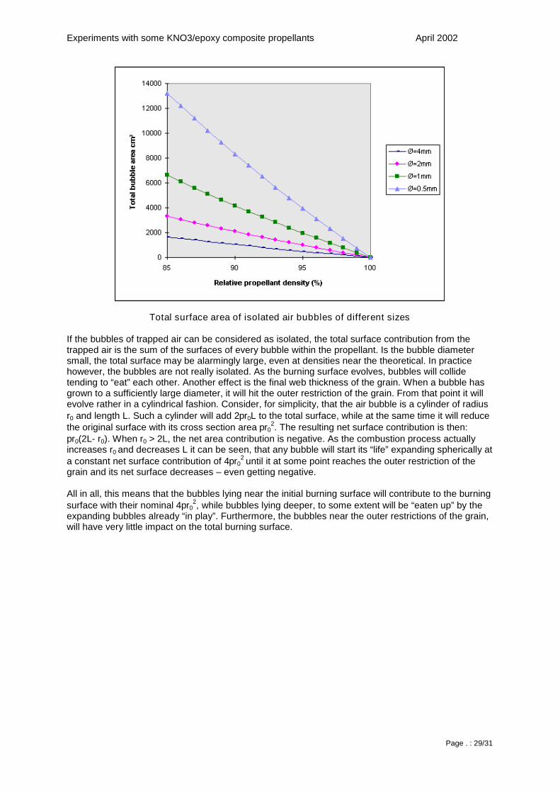
In the case of isolated air bubbles, the total surface contribution is the sum of the surface of allbubbles in the grain. There is also the effect of bubble size: It is easily shown, that dividing the air fromone large bubble into N smaller makes the total bubble surface area increase by a factor of N1/3. Alsothe surface area is inversely proportional to the bubble radius, so at a fixed density, even while thetotal surface does not increase as fast as the number of bubbles, it is still prefereable with a few largebubbles instead of many small.
As an example of the surface area that isolated air bubbles may create, the bubble area is calculatedfor bubbles of various diameters in a propellant segment of 1kg of propellant with a nominal density of1.6g/cm3 and with an actual density of 85-100% of the nominal density. As it can be seen, thediameter of the air bubbles is crucial for the total additional surface area, generated by the bubbles:
Experiments with some KNO3/epoxy composite propellants April 2002
Page . : 29/31
Total surface area of isolated air bubbles of different sizes
If the bubbles of trapped air can be considered as isolated, the total surface contribution from thetrapped air is the sum of the surfaces of every bubble within the propellant. Is the bubble diametersmall, the total surface may be alarmingly large, even at densities near the theoretical. In practicehowever, the bubbles are not really isolated. As the burning surface evolves, bubbles will collidetending to “eat” each other. Another effect is the final web thickness of the grain. When a bubble hasgrown to a sufficiently large diameter, it will hit the outer restriction of the grain. From that point it willevolve rather in a cylindrical fashion. Consider, for simplicity, that the air bubble is a cylinder of radiusr0 and length L. Such a cylinder will add 2πr0L to the total surface, while at the same time it will reducethe original surface with its cross section area πr0
2. The resulting net surface contribution is then:πr0(2L- r0). When r0 > 2L, the net area contribution is negative. As the combustion process actuallyincreases r0 and decreases L it can be seen, that any bubble will start its “life” expanding spherically ata constant net surface contribution of 4πr0
2 until it at some point reaches the outer restriction of thegrain and its net surface decreases – even getting negative.
All in all, this means that the bubbles lying near the initial burning surface will contribute to the burningsurface with their nominal 4πr0
2, while bubbles lying deeper, to some extent will be “eaten up” by theexpanding bubbles already “in play”. Furthermore, the bubbles near the outer restrictions of the grain,will have very little impact on the total burning surface.
Experiments with some KNO3/epoxy composite propellants April 2002
Page . : 30/31
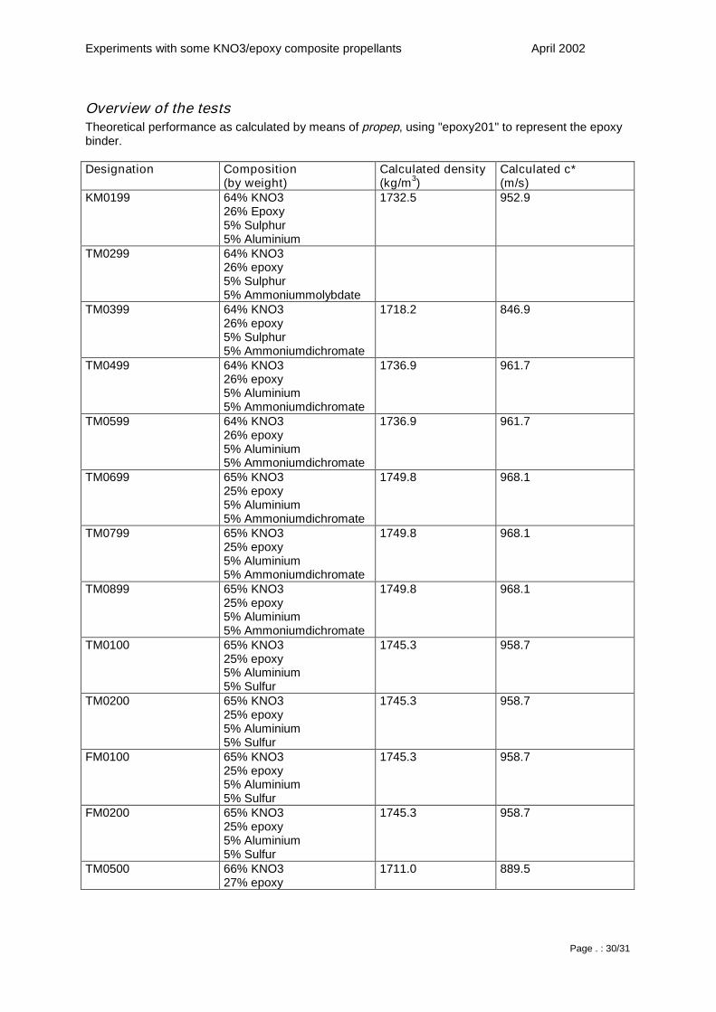
Overview of the testsTheoretical performance as calculated by means of propep, using "epoxy201" to represent the epoxybinder.
Designation Composition(by weight)
Calculated density(kg/m3)
Calculated c*(m/s)
KM0199 64% KNO326% Epoxy5% Sulphur5% Aluminium
1732.5 952.9
TM0299 64% KNO326% epoxy5% Sulphur5% Ammoniummolybdate
TM0399 64% KNO326% epoxy5% Sulphur5% Ammoniumdichromate
1718.2 846.9
TM0499 64% KNO326% epoxy5% Aluminium5% Ammoniumdichromate
1736.9 961.7
TM0599 64% KNO326% epoxy5% Aluminium5% Ammoniumdichromate
1736.9 961.7
TM0699 65% KNO325% epoxy5% Aluminium5% Ammoniumdichromate
1749.8 968.1
TM0799 65% KNO325% epoxy5% Aluminium5% Ammoniumdichromate
1749.8 968.1
TM0899 65% KNO325% epoxy5% Aluminium5% Ammoniumdichromate
1749.8 968.1
TM0100 65% KNO325% epoxy5% Aluminium5% Sulfur
1745.3 958.7
TM0200 65% KNO325% epoxy5% Aluminium5% Sulfur
1745.3 958.7
FM0100 65% KNO325% epoxy5% Aluminium5% Sulfur
1745.3 958.7
FM0200 65% KNO325% epoxy5% Aluminium5% Sulfur
1745.3 958.7
TM0500 66% KNO327% epoxy
1711.0 889.5
Experiments with some KNO3/epoxy composite propellants April 2002
Page . : 31/31
2% Aluminium5% Sulfur
TM0600 68% KNO327% epoxy5% Sulfur
1706.7 854.7
TM0700 66% KNO327% epoxy2% Aluminium5% Sulfur
1711.0 889.5
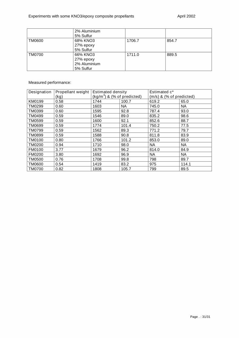
Measured performance:
Designation Propellant weight(kg)
Estimated density(kg/m3) & (% of predicted)
Estimated c*(m/s) & (% of predicted)
KM0199 0.58 1744 100.7 619.2 65.0TM0299 0.60 1603 NA 745.0 NATM0399 0.60 1595 92.8 787.4 93.0TM0499 0.59 1546 89.0 835.2 98.6TM0599 0.59 1600 92.1 852.6 88.7TM0699 0.59 1774 101.4 750.2 77.5TM0799 0.59 1562 89.3 771.2 79.7TM0899 0.59 1588 90.8 811.8 83.9TM0100 0.80 1766 101.2 853.0 89.0TM0200 0.94 1710 98.0 NA NAFM0100 3.77 1679 96.2 814.0 84.9FM0200 3.80 1692 96.9 NA NATM0500 0.76 1708 99.8 798 89.7TM0600 0.54 1419 83.2 975 114.1TM0700 0.82 1808 105.7 799 89.5