Embed Size (px)
Citation preview

any length multipple to 2mwidth 3,0 m
hei
ght
2,4
m
CLA
SS
«T
ITA
NIC
STR
EN
GTH
»
Quality management system (QMS)of LLC «Volya» is certified for compliance withstandard ofISO 9001:2008
Certified by Russian Registry
DACHNAYA STRELKA-3Cellular polycarbonate greenhouse
(EURO)
Technical certificate
Assembling manual
page 2-5
page 6-27

2
Technical certificateTechnical certificate
Table 4 Detailed list of parts for Dachnaya-Strelka-3 greenhouse№ marking name quantity, pcs
Box №11 4н lower arch 62 4в upper arch 63 8 upper door opening stand 44 12 door vertical part 45 - profile L=1,05 m 4
Box №21 1 stand 102 3 support 103 5 butt end upper strainer 24 6 butt end lower strainer 25 6к butt end lower strainer 46 7 lower door opening stand 47 9 horizontal strainer 18 10 side brace 49 11 brace spreader 2
10 13 door horizontal part 611 16 butt end strap 212 17 door strap for the latch 413 18 reinforcement nogging piece 214 21 middle strainer 415 - end reinforcement 416 - ridge profile 217 - hinge strip L=3,6 m 118 - roor strip L=10 m 119 - butt end strip L=6 m 220 - angle 1621 - ridge cover plate 322 - arm 1223 - support hook М4х10 824 - screw М5х10 37225 - screw М5х14 2226 - screw М5х35 12027 - screw М4х35 828 - bolt М5х50 1229 - bolt М6х60 630 - self-tapping screw 631 - nut M4 1632 - nut M5 52633 - nut М6 634 - washer 13235 - washer 6 1236 - top wire bandage 337 - bottom wire bandage 638 - hinges 839 - semifinished rotator (with two elastic headers) 440 - bending tube 141 - adhesive tape 142 - handle 843 - pin 444 - two-side adhesive tape L=5 m 1
Box №31 2 beam 202 14 door diagonal part 43 15 door diagonal strap 44 19 ventilating window horizontal part 45 20 ventilating window vertical part 46 - hooks 4
3
Perform installation and operation of the greenhouse in strict accordance with the manual and operating rules stated in the technical certificate. Please keep this technical certificate for further reference.
DescriptionDACHNAYA STRELKA-3 greenhouse is designed for creation of microclimate
favorable for growing garden crops on cottage and household plots. Area of covered soil depends on length of the greenhouse (table 1). Height of installed frame is 2.4 m, width is 3.0 m. The greenhouse may have various length depending on desire of buyer. Required length of greenhouse is provided by purchase of additional Vstavka packages adding 2 m to the base length (table 2).
Greehouse specifcationsChart 1
Table 3 Box contents
contents dimensions, mm weight max, kg
Frame (base length 2 m)
Box №1– manual, parts of arches and butt ends, profile 70x270x1560 21,0
Box №2 – straight parts for butt ends, arch reinforcements, ridge profile,weather strips beams, fasteners and parts, bandage
60x370x1245 33,0
Box №3 - straight parts and assembly 70x110x1000 20,0
Insert (extending the frame by 2 m)Box №1 – beams, parts of arches and straight parts, ridge profile, fasteners and parts 70x270x1560 36,0
Chart 2 Box supplied
Table 1 Parameters of greenhouselength, m covered area, m2 Polycarbonate sheets 2100 x 6000, pcs
2 6 24 12 36 18 48 24 5
Table 2 Box completing
greenhouse length, m box №1 box №2 box №3 box insert
2 + + +4 + + + +6 + + + ++8 + + + +++
The greenhouse frame is made of zinc-coated iron and assembled with screws and nuts. The greenhouse is fixed to the ground by digging special supports into the soil or by joining it to a foundation slab with fastening hooks. The supply package includes everything you need for fastening the cover surfaces. Cover surface sheets are supplied following the customer’s request. The greenhouse has two door openings and two ventilating windows in the opposite ends. Side ventilating windows are supplied following the customer’s request.

54
Technical certificate
Table 5 Detailed list of parts for extension
№ marking name quantity, pcs
Box №1
1 2 balk 20
2 3 support 4
3 1 stand 4
4 4н bottom arc 4
5 4в top arc 4
6 9 horizontal strainer 2
7 10 side brace 8
8 11 brace strut liner 4
9 18 stiffening boom 4
10 - ridge profile 2
11 - ridge cover plate 2
12 - bottom wire bandage 4
13 - top wire bandage 2
14 - screw M5x10 172
15 - screw M5x14 4
16 - screw M5x35 16
17 - screw M4x10 4
18 - screw M4x35 8
19 - nutM4 12
20 - nut M5 192
21 - nut M6 4
22 - washer 16
23 - washer 6 8
24 - boltМ6х60 4
25 - profile L=1,0 m 4
26 - double sided tape L=5 m 1
Technical certificate
1. Before use of greenhouse, assembleand install it in accordance with the manual.
When installing the greenhouse by third parties, buyer should supervise compliance of installation with the manual
Operating rules
2. In winter, coverage of greenhouseshould not be removed provided that snow load is limited. Should greenhouse be unattended all winter period, buyer should either remove the coverage or estimate possible snow load. Ultimate load for the frame having complete package with installed drawbars and side braces appears under 360 kg snow cover per 1 m2 of horizontal ground surface corresponding to 1.8 m fresh snow layer or 0.9 m packed snow layer. Recommended 4 mm depth of polycarbonate is enough for Russian midland. In case of regions with snow cover exceeding 0.6 m,
Do not install greenhouse close to buildings and trees from which snow or ice can fall down. Minimal 2 m distance is recommended
thicker polycarbonate should be used for coverage of greenhouse top in accordance with local conditions.
Maximum wind pressure for this greenhouse is 25m/sec
Cleaning and washing sheets of polycarbonate.
1. Rinse the sheet with warm water.2. Wash the sheet with a solution of soft soap or with a domestic detergent and warm water, using a soft rag or a sponge to take away the dirt.3. Rinse with cold water and dry with a soft rage to take away the water.
By disinfection of the greenhouse from fungus and biological diseases pathogens do not use “sulphuric sticks”
When cleaning polycarbonate sheets never use abrasives or high-alkali cleaning compositions. Dry wiping of the surface can damage the protective layer and reduce its life cycle. Never use brushes, gauze fabric or other abrasive materials to wipe the surface of polycarbonate sheets

76
Technical certificate Manual
Warranty responsibility
1. The manufacturer shall be responsible for the complete set of parts for the greenhouse frame.2. The manufacturer shall be responsible for assemblability of the greenhouse in accordance with the manual.3. The manufacturer shall be responsible for the greenhouse endurance in the specified weather conditions.4. Time period for making claims is 24 months after the day of purchase.
Warranty provisions
Warranty responsibility shall not cover the following cases:
1. Installation of the greenhouse in violation of the manual provisions.2. Violation of operation rules.3. Unintended use of the greenhouse.4. Deformation of the greenhouse due to soil movement.5. Floods, hurricanes and other natural disasters.
Manufacturer: LLC Volia141983, city of Dubna, Moscow Region, 8 Severny Lane.
The manufacturer shall be responsible for the quality of products in accordance with the Civil Code of the Russian Federation.
The manufacturer shall retain the right to make changes to the greenhouse design.
Production date:
Warranty responsibility Installation manual for Dachnaya-Strelka-3 greenhouse
1. General view of the frame is given in Picture 1. Parts should be installed in such a way that side selves of the profile are facing the surface cover. The frame is assembled of numbered parts.
2. Symbols: -arrow shows the direction of installation as per schemes in the manual.
3. Parts are fastened by putting profiles together and fastening them with screws and nuts through the holes. When joining parts in “profile-to-profile” way it does not matter which of the joined parts is above.
4. When assembling be careful not to damage the parts as they do not have sufficient endurance before the whole structure is assembled. Use supports (e.g. chairs) at interim stages of assembly to make sure the frame is lifted steadily and evenly. To make sure holes coincide when assembling complicated joints, use a 5 mm thick nail or a cone-shaped hand-punch.
Some parts may have spare holes which are there due to uniformity of parts
introduction
Be careful when assembling the greenhouse! Parts have sharp edges. Beware of cuts! Perform all works in protective gloves
When assembling the frame parts should be joined through all holes as prescribed. A simplified fastening of parts with only one or two screws is the violation of assembly rules and the ground to relieve the manufacturer of the warranty responsibility

98
Manual
General view of DACHNAYA-STRELKA-3 greenhouse frame
B (inside view)А (outside view)
4В
angleangle
4В2 2
4Н6к 2
1arm
4Н
Manual
General view of DACHNAYA-STRELKA-3 greenhouse frame
F (outside view)
4В5
arm
7
1
6к6
C (inside view)
4Н
2
3
1
Pic. 1
D (outside view) E (inside view)
Dachnaya-Strelka-3 extended by any number of inserts.
Pic. 2
Pic. 3
858
40
60
10
00
10
00
10
00
10
00
3000
Greenhouse foundation support layout plan.
Pic. 4
А
E
C
B
F
D
1071
arm
22
22
22
2
2
2
2
2
2
4в
4н
4н
4в
8
8
5
6к
6
7 7
6к
10
10
10
21
1818
99
918
5
21
11
11
3
3
1
1
60
21
ridgecover
General view of insert for Dachnaya Strelka-3 greenhouse.Each insert extends greenhouse length by 2 m.

1110
Assemble arcs 4в in pairs using ridge coverplate and strainer 9. Connect end elements 5 to arcs 4в using arm.
Connect balks 2 toassembled arcs.
2
2
4в
Assembling stages
Pic. 5
Pic.6
4. Level the frame using filling or deepening of pits to make longitudinal elements straight, horizontal and parallel to each other and to make arcs even at side view. If arc planes require leveling, loosen connections of balks with arcs, complete leveling on the ground and tight screws again. Fill frame supports with soil after fastening bottom wire bandages on element 3 (Pic.10)
1. Perform the installation close to location of the greenhouse.
2. Install greenhouse in accordance with photographs of installation stages and units represented in Pic. 5…12. The figures show installation of greenhouse of 4 m length. Required length is reached using attachment of appropriate number of Insert packages. Use M5x10 screws for connection of elements.
3. Dig pits on the site selected for greenhouse installation at a depth of shovel blade according to Pic. 4 Install frame into the pits. Check equality of frame diagonals using a cord. Total draft of greenhouse into the ground should be so that bottom elements 6 of door opening touch the ground. Check equality of the diagonals using a cord again and correct position of the frame angles.
Installation sequence
When installing the greenhouse through digging (without foundation), connect elements 1 and 3 to the frame. Fasten bottom wire bandage in free hole of element 3. Install end elements 6, 6к, 7, 8, 21.
Pic.10
2
6к
4н
21
arm
6к
Pic. 7
Connect arcs 4н to arcs4в from one side ofgreenhouse.
Connect balks 2 to arcs 4н
Pic.9
Connect arcs 4н and balks 2 from the other side of reenhouse in the same way.
Assembling stages
4в
55
5
2
22
2
2
2
2
22
2
2
2
arm
Manual Manual
4н4н
4в4в
4в4в
4в
4н
4н4н
4н
4н4н
4н4н
4н
4н 4н4н 4н 4н
4в
(inside view) (outside view)
arm
Pic. 8
ridge cover plate
4в
4в4в
4в4в
4в4в
4в4в4в
4в
Б
4в
9
99
9
4н2
2
4н 2
2
2
6к
8
21
21
8
77
6 6к 3
1
22 2
22
2
А
B
АB-1, B-2
C
А
А А
B
C
3
13
1
bottom wire bandage
bottom wire bandage
B-1 B-2adhesive tape
screw М5х10
screw М4х10

1312
Install side braces 10 on each arc inside of greenhouse frame. Assemble side brace assembled from two elements 10. Mount side brace liner 11 on the joint of elements 10 and connect it to arc 4н.
Door
9
9
18
18
10
4в
10
2
2
Assembling stages
Manual Manual
Assembled door and end small window
Assemble door and end small window fromelements 12, 13, 14, 15 (Pic.12)
4н
4в
14
14
14
1212
12 12
12
13
15
15
15
15
19
19
20 20
1415
B
Pic. 12
А
12
13
14
13
13
13
13
15
14
14
14
12
13
Small window
Pic. 11
G F
А
B
CD
11
10
10
4н
1920
А
А
D
GF
B
B
C

1514
60
00
Door
low
er b
and
Door
small window
Left end side
Left end side/template/
Right endside
Right endside
14
90
19
40
2100
1110
800
800
310
310
Cu
ttin
g lin
e
Ridgepanel
Ridgepanel
Manual Manual
Cutting and fastening of coverage
1. Cut a sheet for end coverage. To do this, cut a piece from polycarbonate sheet (see cutting lines on Pic.13а or Pic. 13b). To make a stencil of coverage, put the cut piece to assembled end of greenhouse and, without removal of protective film from polycarbonate, deposit stencil marking on the coverage sheet by elements 4н and 4в (with allowance Pic.14) . When marking a sheet, align its edge strictly with edges
Attention! Coverage sheet side edge is aligned by elements 7, 8, and top edge on 30 mm above bottom edge of element 5. Mark by elements 4н and 4в with allowance
Mount cellular polycarbonate strictly facing sun with a side having protective layer (by all means, clarify it under purchase or before mounting). Protective layer usually is on the side with inscriptions on transport film. On the other side of sheet film is clear. After marking the sheet but before its cutting make marks on protective side of each piece of sheet: after removal of transport film sheet sides have no visual differences. Transport film is removed from both sides immediately before fastening coverage on the frame
CUT POLYCARBONATE SHEET STRICTLY IN ACCORDANCE WITH Pic. 13(а) or 13(b) and Pic. 14
2100 x 600 mm cellular polycarbonate sheet
Pic. 13аVertical position of cellular on ridge
pane
Pic. 13bHorizontal position of cellular on ridge
panel
Pic. 14
8
5
2
4в
coverage
marking
2100
30
mm
marking
- points for mounting of armsfor coverage fastening
angle
19
40
19
40
of elements 7 and 8, and top edge at 30 mm above bottom edge of element 5. Cut a stencil. Mark the rest of sheet using the stencil in accordance with cutting scheme Pic.13а or Pic 13b.
Cu
ttin
g lin
eC
utt
ing
line
A power jigsaw or fine tooth arm saw is recommended for cutting
Warning! When cutting the surface cover in windy weather, fix the edges of polycarbonate sheets with a load.
Left end side
Left end side
Door
Door
Rightendside
Right endside/template/
small window
small window
small window

1716
hinge
Manual Manual
Раскрой и крепление покрытия торцаCutting and fastening of coverage
Pic. 15
2. Cut ridge coverage pieces located above the door atthe place of installation from remaining pieces. Mark marking 4в coverage by elements 4в with allowance aligning bottom edge of the sheet with bottom edge of element 5 (Pic.15).
marking 4в
5
Cutting and fastening of coverage
Pic.19
adhesive tape
door sealer
doo
r se
aler
hinge sealer
hinge sealer
сoverage
сoverage
сoverage
17
screw М5х14
handle
handle
сoverage
adhesive tape
door sealer
hinge
adhesive tape
door sealerhinge sealerсoverage
door sealer
door sealer
сoveragehinge
hinge
adhesive tape
adhesive tape
сoverage
Avoid over-tightening screws that fasten the polycarbonate in order not to damage the polycarbonate sheet and destroy its structure
Pic.16
3. Mount side pieces of coverage in accordance with Pic.16. Holding a piece of coverage, fasten it with screws and washers by elements 6к, 7, 8, 21 and by angles using tap screws with washers. Holes for screws are drilled by boring bit of 5 mm diameter from inside of greenhouse through holes in frame elements. Mount top pieces of coverage fastening them on angles with washers and tap screws. Cut overlapping with side pieces.
4. Even coverage pieces by arcs 4н and 4в using a knife and mount sealing profile in accordance with Pic.17.
5. Fasten pieces of coverage on door with washers (Pic.18,19). Fasten pieces of coverage on door with washers (Pic.23), closing cellular beforehand (with adhesive tape). Mount sealing profiles along the door contour in accordance with Pic. 19,21,22.
Pic.17
Pic.18
details 4В, 4Н and 1
end sealing
сoverageWasher
screw М5х35
Pro
tect
ive
laye
r
angle
washer
washer
endсoverage
Protective layer
pin

1918
Manual
Cutting and fastening of coverage
Manual
Cutting and fastening of coverage
8. The washers and the hooks on the end install in accordance with Pic.24.
Pic.24
washer
washerhook
end сoverage
angle
angle
screw М4х10
screw М5х35
The ground
7. Install assembled doors and smallwindows on ends mounting sealer in accordance with Pic.22.When mounting small windows, prevent its further slackening. When tightening the screws, lift the opposite end of small window to remove screw gaps in the holes.
Pic.23
end сoverage20..25mm
(the output of surface contour door)
door
washer
12
8screw М5х35
scre
wМ
5х3
5
doorсoverage
small window сoverage
doorсoverage
ridgedpanel
16
16
screw М5х50
screw М5х35
5
doo
r se
aler
doo
r se
aler
door sealer
19
19
13
13
6
smal
l win
dow
Pic.20
end сoverage
scre
w М
5х3
5
screw М5х10screwМ5х10
hinge sealer
hingeswasher washer
washer
washer
washer
12
door
Pic.21
6. Mount end cover plate 16 on end coverage and fasten it on element 5 through coverage (Pic.20 and Pic.24). Joint of end coverage pieces is under element 16.
doo
r se
aler
doo
r se
aler
screw М5х35
screw М5х35
screw М5х35
screw М5х35
Pic.22 9. Install end reinforcing element door opening in accordance with Pic.25
Рiс.25
2
8
end reinforcing

Manual Manual
2120
Cutting and fastening of coverageCutting and fastening of coverage
10. Insert wire rotatorfor door closing in free holes (against the stop) through elements 12 and 17 by straight end from inside (Pic. 26). In this position,use the tube to bend linear part by hand
into opposite outside of the greenhouse direction (Pic. 27). Set elastic header on the rotator (Pic. 28). This construction allows to push the door in the closed position, being
both outside and inside the greenhouse.
Pic.26 Pic.27 Pic.28
17
17
bending tube
bending tube
handle 12
20
11. Wire rotator for small window locking is mounted like a door rotator.
rotator
12. Cellular polycarbonate shall be installed strictly defined side out (towards the sun), which has a protective layer. The protective layer is usually at the side with the inscriptions on the transport film. The film on the other side of sheet is transparent. After marking the sheet, but prior to its cutting, make a mark on the protected side of the sheet for each piece: after removal of the transport film sheet sides are not visually different. The transport film is stripped from both sides immediately before fixing the cladding on the frame.
Sections of polycarbonate with open honeycombs should be covered by adhesive tape.
12000
2000
10
00
10
54
21
00
For Dachnaya-Strelka-3 greenhouse length by 4 m
Manual Manual
2322
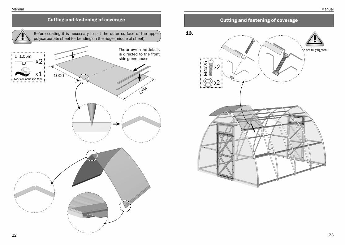
Cutting and fastening of coverageCutting and fastening of coverage
х2
M4
x25
х2
13.
1000х1
х2L=1,05m
Two-side adhesive tape
Before coating it is necessary to cut the outer surface of the upper polycarbonate sheet for bending on the ridge (middle of sheet)!
The arrow on the details is directed to the front side greenhouse
1054
do not fully tighten!

Manual Manual
2524
14.
х1
Adhesive tape
15.
х4
х4
M4
x35
х4
Cutting and fastening of coverageCutting and fastening of coverage
1054

Manual Manual
2726
17. Details of ridge profile are joined in the length with the installation of the threaded end of the screws out.
screw М5х14
ridgeprofile х1
M6
x60 M
6
х1
х2
х1х1
top wirebandage
M6
x60 M
6
х1
х2
х1х1
top wirebandage
Cutting and fastening of coverage Cutting and fastening of coverage
16.
х1
х2
M4
x25
х2
L=1,0m
1000

Manual
28
ManufacturerLLC Volia, city of Dubna, Moscow Region.
tel/fax: (495) 598-5-999 www.perchina.ru
e-mail: [email protected]
This manual cannot be reproduced in any form, fully or partially, without written consent of Volia LLC