Embed Size (px)
DESCRIPTION
DAELIM NS125
Citation preview
SERVICE MANUAL
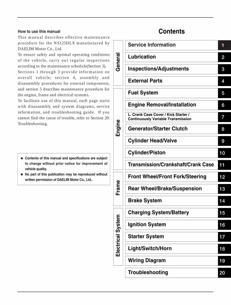
How to use this manualThis manual describes effective maintenanceprocedure for the NS125DLX manufactured byDAELIM Motor Co., Ltd.To ensure safety and optimal operating conditionsof the vehicle, carry out regular inspectionsaccording to the maintenance schedule(Section 3).Sections 1 through 3 provide information onoverall vehicle; section 4, assembly anddisassembly procedures for external components,and section 5 describes maintenance procedure forthe engine, frame and electrical systems.To facilitate use of this manual, each page startswith disassembly and system diagrams, serviceinformation, and troubleshooting guide. If youcannot find the cause of trouble, refer to Section 20:Troubleshooting.
Contents of this manual and specifications are subjectto change without prior notice for improvement ofvehicle quality.
No part of this publication may be reproduced withoutwritten permission of DAELIM Motor Co., Ltd..
Service Information 1
2
3
4
5
6
7
8
9
10
11
12
13
14
15
16
17
18
19
20
Lubrication
Inspections/Adjustments
External Parts
Fuel System
Engine Removal/Installation
L. Crank Case Cover / Kick Starter /Continuously Variable Transmission
Generator/Starter Clutch
Cylinder Head/Valve
Cylinder/Piston
Transmission/Crankshaft/Crank Case
Front Wheel/Front Fork/Steering
Rear Wheel/Brake/Suspension
Brake System
Charging System/Battery
Ignition System
Starter System
Light/Switch/Horn
Wiring Diagram
Troubleshooting
Contents
Eng
ine
Gen
eral
Fram
eE
lect
rica
l Sys
tem
Service Information
1-1
General Safety
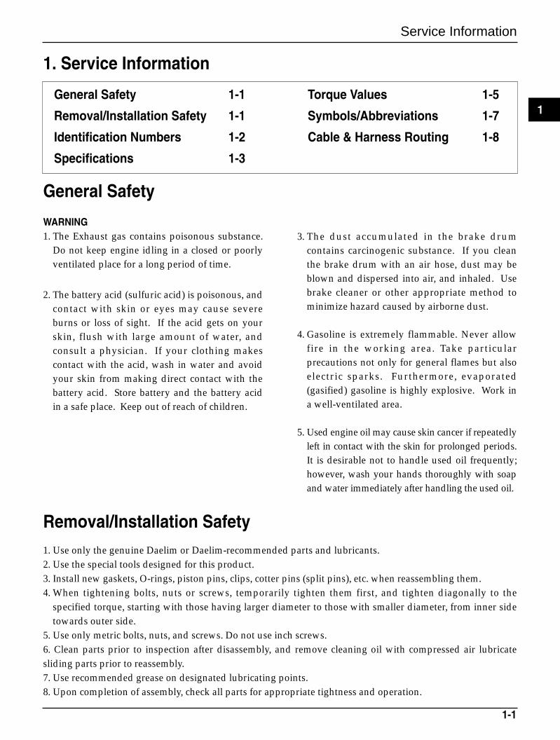
WARNING1. The Exhaust gas contains poisonous substance.
Do not keep engine idling in a closed or poorlyventilated place for a long period of time.
2. The battery acid (sulfuric acid) is poisonous, andcontact with skin or eyes may cause severeburns or loss of sight. If the acid gets on yourskin, flush with large amount of water, andconsult a physician. If your clothing makescontact with the acid, wash in water and avoidyour skin from making direct contact with thebattery acid. Store battery and the battery acidin a safe place. Keep out of reach of children.
3. The dust accumulated in the brake drumcontains carcinogenic substance. If you cleanthe brake drum with an air hose, dust may beblown and dispersed into air, and inhaled. Usebrake cleaner or other appropriate method tominimize hazard caused by airborne dust.
4. Gasoline is extremely flammable. Never allowfire in the working area. Take particularprecautions not only for general flames but alsoelectric sparks. Furthermore, evaporated(gasified) gasoline is highly explosive. Work ina well-ventilated area.
5. Used engine oil may cause skin cancer if repeatedlyleft in contact with the skin for prolonged periods.It is desirable not to handle used oil frequently;however, wash your hands thoroughly with soapand water immediately after handling the used oil.
Removal/Installation Safety1. Use only the genuine Daelim or Daelim-recommended parts and lubricants.2. Use the special tools designed for this product.3. Install new gaskets, O-rings, piston pins, clips, cotter pins (split pins), etc. when reassembling them.4. When tightening bolts, nuts or screws, temporarily tighten them first, and tighten diagonally to the
specified torque, starting with those having larger diameter to those with smaller diameter, from inner sidetowards outer side.
5. Use only metric bolts, nuts, and screws. Do not use inch screws.6. Clean parts prior to inspection after disassembly, and remove cleaning oil with compressed air lubricatesliding parts prior to reassembly.7. Use recommended grease on designated lubricating points.8. Upon completion of assembly, check all parts for appropriate tightness and operation.
General Safety 1-1
Removal/Installation Safety 1-1
Identification Numbers 1-2
Specifications 1-3
Torque Values 1-5
Symbols/Abbreviations 1-7
Cable & Harness Routing 1-8
1. Service Information
1
Service Information
1-2
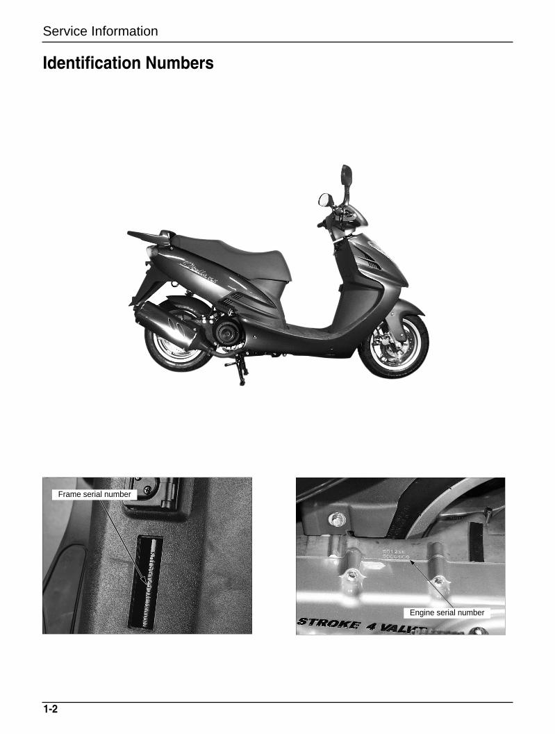
Identification Numbers
Frame serial number
Engine serial number
Service Information
1-3
Item Specifications
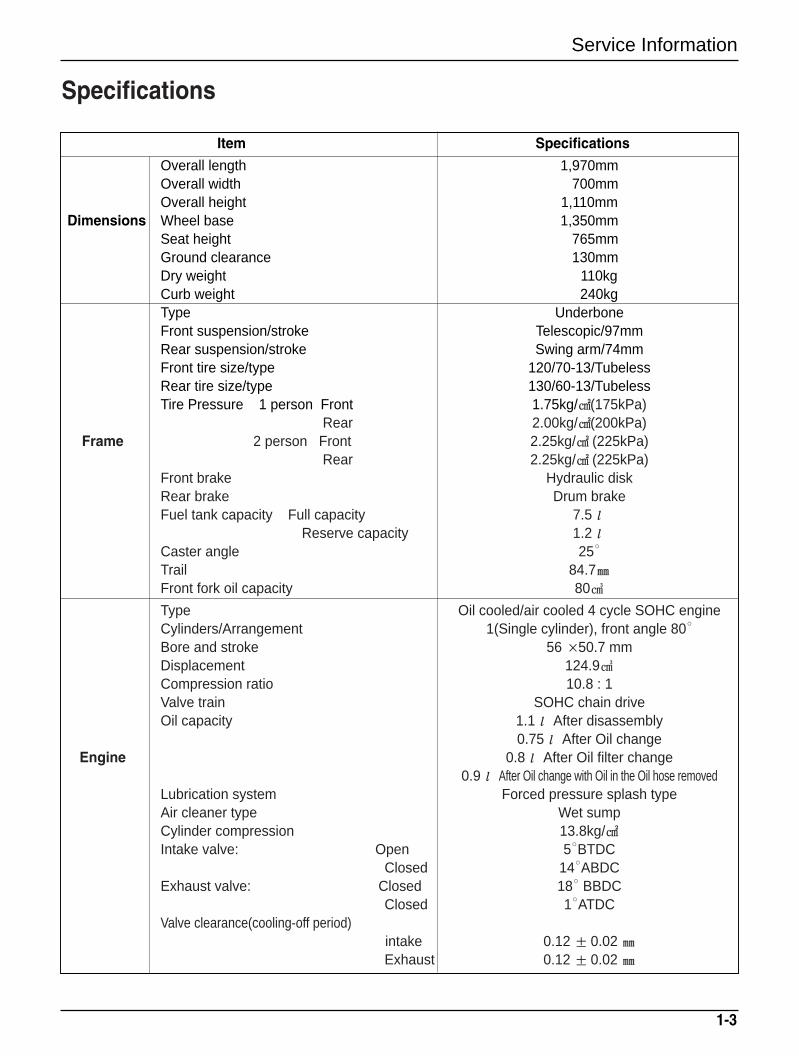
Overall length 1,970mmOverall width 700mmOverall height 1,110mm
Dimensions Wheel base 1,350mmSeat height 765mmGround clearance 130mmDry weight 110kgCurb weight 240kgType UnderboneFront suspension/stroke Telescopic/97mmRear suspension/stroke Swing arm/74mmFront tire size/type 120/70-13/TubelessRear tire size/type 130/60-13/TubelessTire Pressure 1 person Front 1.75kg/(175kPa)
Rear 2.00kg/(200kPa)Frame 2 person Front 2.25kg/ (225kPa)
Rear 2.25kg/ (225kPa)Front brake Hydraulic diskRear brake Drum brakeFuel tank capacity Full capacity 7.5ℓ
Reserve capacity 1.2ℓCaster angle 25
Trail 84.7Front fork oil capacity 80
Type Oil cooled/air cooled 4 cycle SOHC engineCylinders/Arrangement 1(Single cylinder), front angle 80
Bore and stroke 56 ×50.7 mmDisplacement 124.9Compression ratio 10.8 : 1Valve train SOHC chain driveOil capacity 1.1ℓ After disassembly
0.75ℓ After Oil changeEngine 0.8ℓ After Oil filter change
0.9ℓ After Oil change with Oil in the Oil hose removedLubrication system Forced pressure splash typeAir cleaner type Wet sumpCylinder compression 13.8kg/Intake valve: Open 5BTDC
Closed 14ABDCExhaust valve: Closed 18 BBDC
Closed 1ATDCValve clearance(cooling-off period)
intake 0.12 ± 0.02 Exhaust 0.12 ± 0.02
Specifications
Service Information
1-4
Item Specifications
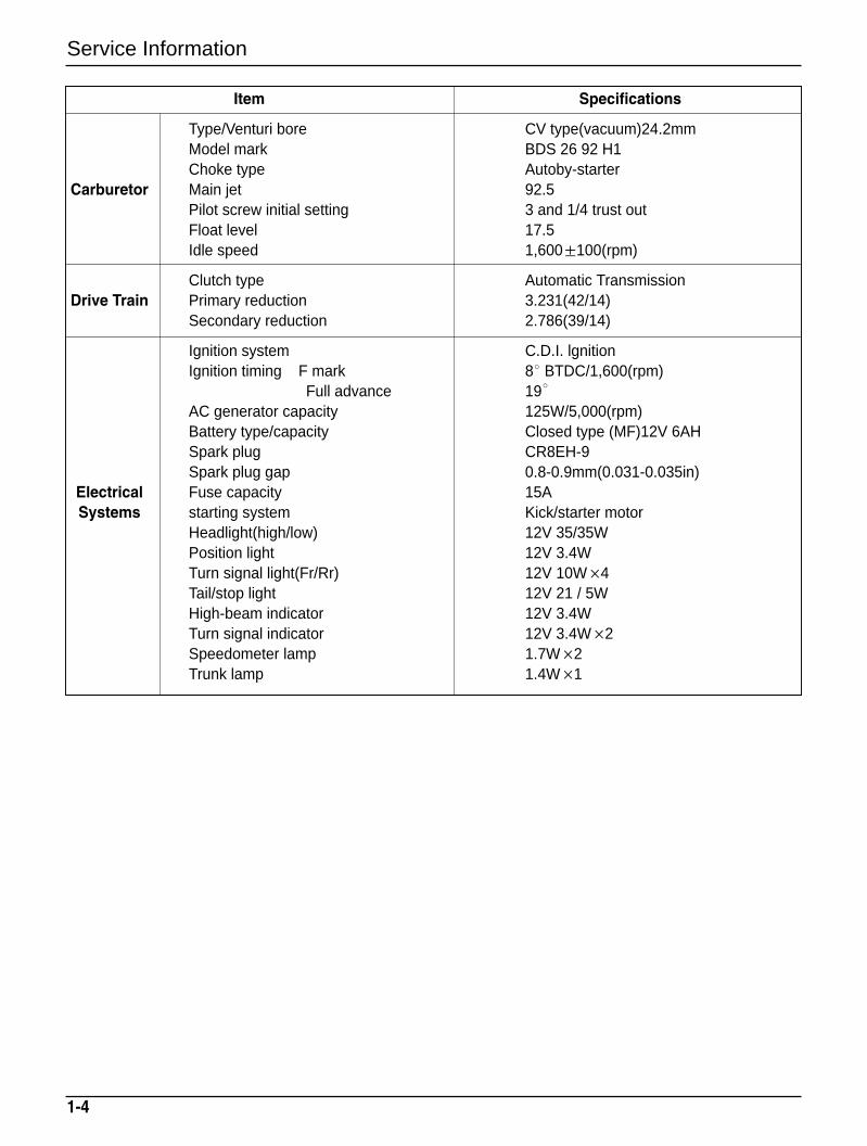
Type/Venturi bore CV type(vacuum)24.2mmModel mark BDS 26 92 H1 Choke type Autoby-starter
Carburetor Main jet 92.5Pilot screw initial setting 3 and 1/4 trust outFloat level 17.5Idle speed 1,600±100(rpm)
Clutch type Automatic TransmissionDrive Train Primary reduction 3.231(42/14)
Secondary reduction 2.786(39/14)
Ignition system C.D.I. lgnitionIgnition timing F mark 8 BTDC/1,600(rpm)
Full advance 19
AC generator capacity 125W/5,000(rpm)Battery type/capacity Closed type (MF)12V 6AHSpark plug CR8EH-9Spark plug gap 0.8-0.9mm(0.031-0.035in)
Electrical Fuse capacity 15ASystems starting system Kick/starter motor
Headlight(high/low) 12V 35/35WPosition light 12V 3.4WTurn signal light(Fr/Rr) 12V 10W×4Tail/stop light 12V 21 / 5WHigh-beam indicator 12V 3.4WTurn signal indicator 12V 3.4W×2Speedometer lamp 1.7W×2Trunk lamp 1.4W×1
Service Information
1-5
Item Q’ty Thread dia(mm)Torque value
Remarkskg.m(N.m,ft-lb)
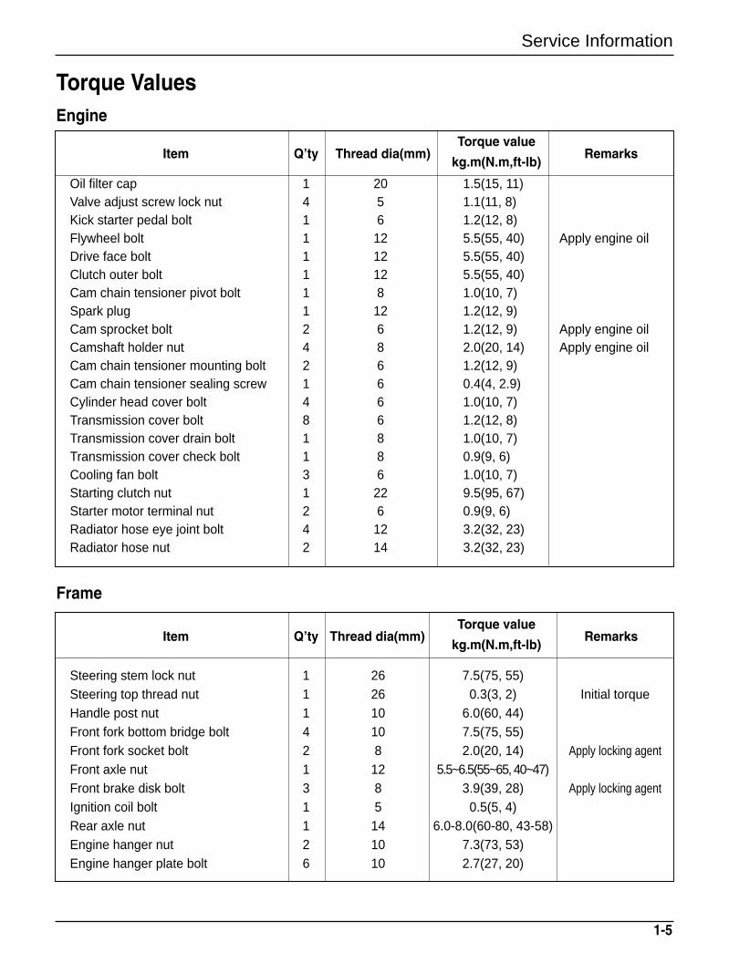
Oil filter cap 1 20 1.5(15, 11)Valve adjust screw lock nut 4 5 1.1(11, 8)Kick starter pedal bolt 1 6 1.2(12, 8)Flywheel bolt 1 12 5.5(55, 40) Apply engine oilDrive face bolt 1 12 5.5(55, 40)Clutch outer bolt 1 12 5.5(55, 40)Cam chain tensioner pivot bolt 1 8 1.0(10, 7)Spark plug 1 12 1.2(12, 9)Cam sprocket bolt 2 6 1.2(12, 9) Apply engine oilCamshaft holder nut 4 8 2.0(20, 14) Apply engine oilCam chain tensioner mounting bolt 2 6 1.2(12, 9)Cam chain tensioner sealing screw 1 6 0.4(4, 2.9)Cylinder head cover bolt 4 6 1.0(10, 7)Transmission cover bolt 8 6 1.2(12, 8)Transmission cover drain bolt 1 8 1.0(10, 7)Transmission cover check bolt 1 8 0.9(9, 6)Cooling fan bolt 3 6 1.0(10, 7)Starting clutch nut 1 22 9.5(95, 67)Starter motor terminal nut 2 6 0.9(9, 6)Radiator hose eye joint bolt 4 12 3.2(32, 23)Radiator hose nut 2 14 3.2(32, 23)
Torque ValuesEngine
Item Q’ty Thread dia(mm)Torque value
Remarkskg.m(N.m,ft-lb)
Steering stem lock nut 1 26 7.5(75, 55)Steering top thread nut 1 26 0.3(3, 2) Initial torqueHandle post nut 1 10 6.0(60, 44)Front fork bottom bridge bolt 4 10 7.5(75, 55)Front fork socket bolt 2 8 2.0(20, 14) Apply locking agentFront axle nut 1 12 5.5~6.5(55~65, 40~47)Front brake disk bolt 3 8 3.9(39, 28) Apply locking agentIgnition coil bolt 1 5 0.5(5, 4)Rear axle nut 1 14 6.0-8.0(60-80, 43-58)Engine hanger nut 2 10 7.3(73, 53)Engine hanger plate bolt 6 10 2.7(27, 20)
Frame
1-6
Service Information
Item Q’ty Thread dia(mm)Torque value
Remarkskg.m(N.m,ft-lb)
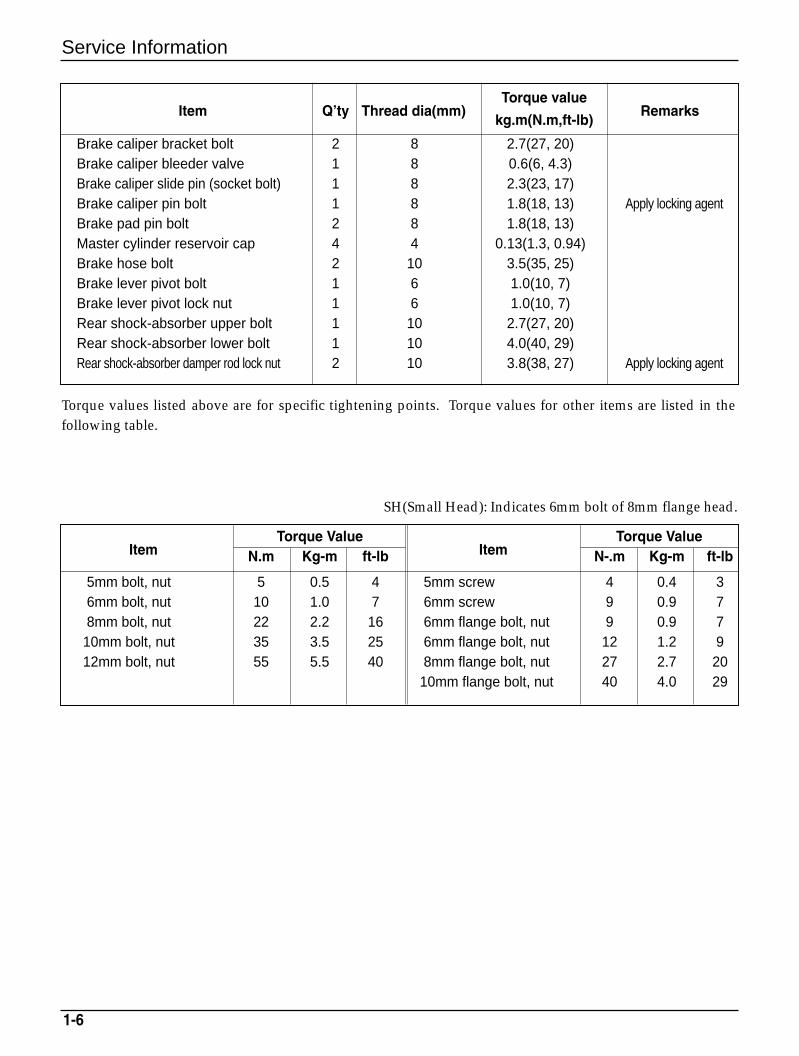
Brake caliper bracket bolt 2 8 2.7(27, 20)Brake caliper bleeder valve 1 8 0.6(6, 4.3)Brake caliper slide pin (socket bolt) 1 8 2.3(23, 17)Brake caliper pin bolt 1 8 1.8(18, 13) Apply locking agentBrake pad pin bolt 2 8 1.8(18, 13)Master cylinder reservoir cap 4 4 0.13(1.3, 0.94)Brake hose bolt 2 10 3.5(35, 25)Brake lever pivot bolt 1 6 1.0(10, 7)Brake lever pivot lock nut 1 6 1.0(10, 7)Rear shock-absorber upper bolt 1 10 2.7(27, 20)Rear shock-absorber lower bolt 1 10 4.0(40, 29)Rear shock-absorber damper rod lock nut 2 10 3.8(38, 27) Apply locking agent
Torque values listed above are for specific tightening points. Torque values for other items are listed in thefollowing table.
SH(Small Head): Indicates 6mm bolt of 8mm flange head.
ItemTorque Value
ItemTorque Value
N.m Kg-m ft-lb N-.m Kg-m ft-lb
5mm bolt, nut 5 0.5 4 5mm screw 4 0.4 36mm bolt, nut 10 1.0 7 6mm screw 9 0.9 78mm bolt, nut 22 2.2 16 6mm flange bolt, nut 9 0.9 7
10mm bolt, nut 35 3.5 25 6mm flange bolt, nut 12 1.2 912mm bolt, nut 55 5.5 40 8mm flange bolt, nut 27 2.7 20
10mm flange bolt, nut 40 4.0 29
Service Information
1-7
Symbols/Abbreviations
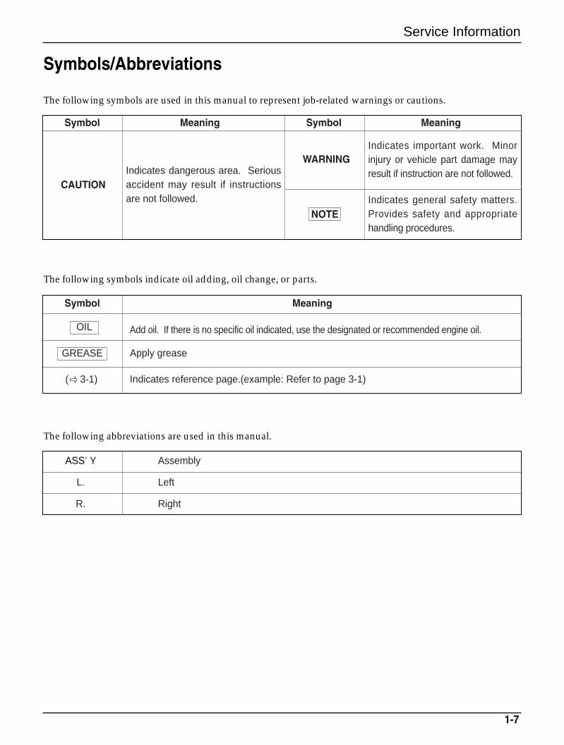
The following symbols are used in this manual to represent job-related warnings or cautions.
The following symbols indicate oil adding, oil change, or parts.
The following abbreviations are used in this manual.
ASS’Y Assembly
L. Left
R. Right
Symbol Meaning
Add oil. If there is no specific oil indicated, use the designated or recommended engine oil.
Apply grease
( 3-1) Indicates reference page.(example: Refer to page 3-1)
Symbol Meaning Symbol Meaning
OIL
GREASE
WARNING
NOTE
Indicates dangerous area. Seriousaccident may result if instructionsare not followed.
Indicates important work. Minorinjury or vehicle part damage mayresult if instruction are not followed.
Indicates general safety matters.Provides safety and appropriatehandling procedures.
CAUTION
1-8
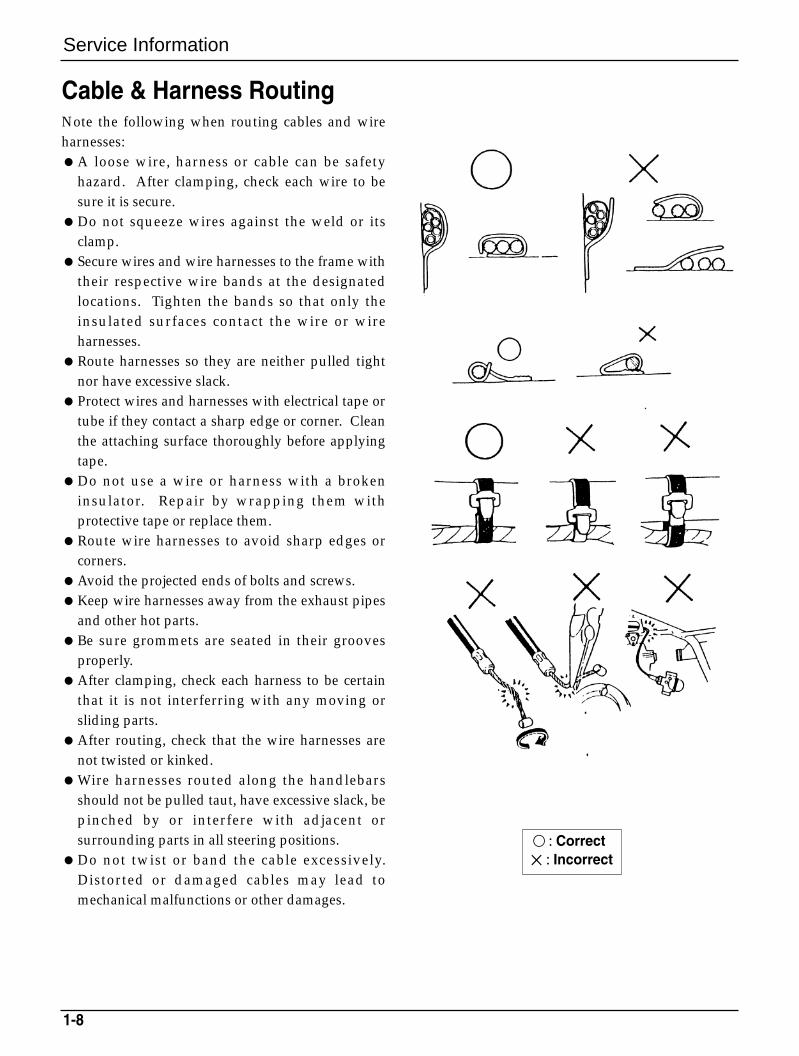
Cable & Harness RoutingNote the following when routing cables and wireharnesses:A loose wire, harness or cable can be safety
hazard. After clamping, check each wire to besure it is secure.
Do not squeeze wires against the weld or itsclamp.
Secure wires and wire harnesses to the frame withtheir respective wire bands at the designatedlocations. Tighten the bands so that only theinsulated surfaces contact the wire or wireharnesses.
Route harnesses so they are neither pulled tightnor have excessive slack.
Protect wires and harnesses with electrical tape ortube if they contact a sharp edge or corner. Cleanthe attaching surface thoroughly before applyingtape.
Do not use a wire or harness with a brokeninsulator. Repair by wrapping them withprotective tape or replace them.
Route wire harnesses to avoid sharp edges orcorners.
Avoid the projected ends of bolts and screws.Keep wire harnesses away from the exhaust pipes
and other hot parts.Be sure grommets are seated in their grooves
properly.After clamping, check each harness to be certain
that it is not interferring with any moving orsliding parts.
After routing, check that the wire harnesses arenot twisted or kinked.
Wire harnesses routed along the handlebarsshould not be pulled taut, have excessive slack, bepinched by or interfere with adjacent orsurrounding parts in all steering positions.
Do not twist or band the cable excessively.Distorted or damaged cables may lead tomechanical malfunctions or other damages.
Service Information
: Correct×: Incorrect
1-9
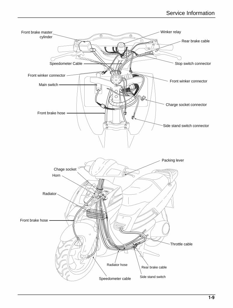
Service Information
Rear brake cable
Winker relay
Stop switch connector
Front winker connector
Side stand switch connector
Charge socket connector
Front brake hose
Horn
Chage socket
Radiator
Packing lever
Front brake hose
Speedometer cable
Rear brake cable
Side stand switch
Radiator hose
Throttle cable
Main switch
Front winker connector
Speedometer Cable
Front brake mastercylinder
1-10
Service Information
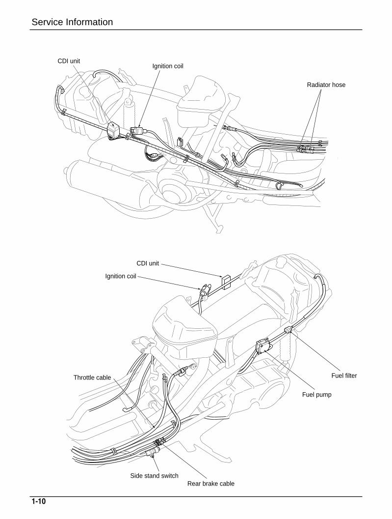
CDI unitIgnition coil
Radiator hose
CDI unit
Ignition coil
Throttle cable
Rear brake cableSide stand switch
Fuel pump
Fuel filter
Lubrication
2-1
2. Lubrication
Service InformationGeneral SafetyWARNING1. The exhaust gas contains poisonous substance. Do not keep engine idling in a closed or poorly ventilated
place for a long period of time.
2. Used engine oil may cause skin cancer if repeatedly left in contact with the skin for prolonged periods. It isdesirable not to handle used oil frequently; however, wash your hands thoroughly with soap and waterimmediately after handling the used oil.
3. The oil pump can be serviced without removing the engine from the frame.
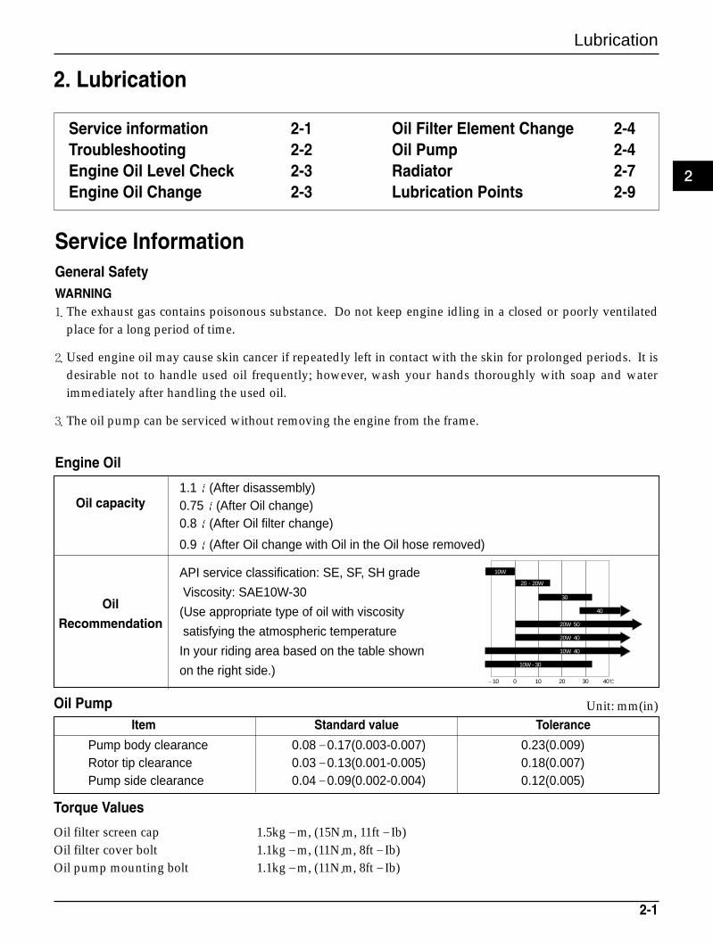
Engine Oil
API service classification: SE, SF, SH grade
Oil Viscosity: SAE10W-30
Recommendation(Use appropriate type of oil with viscosity
satisfying the atmospheric temperature
In your riding area based on the table shown
on the right side.)
1.1 (After disassembly)Oil capacity 0.75 (After Oil change)
0.8 (After Oil filter change)
0.9 (After Oil change with Oil in the Oil hose removed)
20·20W
10W
30
40
20W 50
20W 40
10W 40
10W - 30
–10 0 10 20 30 40
Pump body clearance 0.08–0.17(0.003-0.007) 0.23(0.009)Rotor tip clearance 0.03–0.13(0.001-0.005) 0.18(0.007)Pump side clearance 0.04–0.09(0.002-0.004) 0.12(0.005)
Oil filter screen cap 1.5kg–m, (15N.m, 11ft–Ib)Oil filter cover bolt 1.1kg–m, (11N.m, 8ft–Ib)Oil pump mounting bolt 1.1kg–m, (11N.m, 8ft–Ib)
Item Standard value Tolerance
Oil Pump
Torque Values
Unit: mm(in)
2
Service information 2-1Troubleshooting 2-2Engine Oil Level Check 2-3Engine Oil Change 2-3
Oil Filter Element Change 2-4Oil Pump 2-4Radiator 2-7Lubrication Points 2-9
Lubrication
2-2
TroubleshootingOil level too low - high oil consumptionExternal oil leaksWorn piston ringsWorn valve guide or seal
Oil contamination Oil or filter not changed often enoughHead gasket faultyWorn piston rings
Low oil pressureOil level nowPressure relief valve stuck openPlugged oil pick-up screenOil pump wornExternal oil leaks
High oil pressurePressure relief valve stuck closedPlugged oil filter, gallery, or metering orifice Incorrect oil being used
No oil pressureOil level lowOil Pump drive gear brokenOil pump faulty Internal oil leakage
Lubrication
2-3
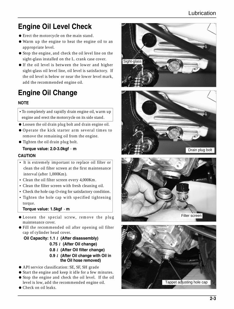
Engine Oil Level CheckErect the motorcycle on the main stand.Warm up the engine to heat the engine oil to an
appropriate level.Stop the engine, and check the oil level line on the
sight-glass installed on the L. crank case cover. If the oil level is between the lower and higher
sight-glass oil level line, oil level is satisfactory. Ifthe oil level is below or near the lower level mark,add the recommended engine oil.
Engine Oil ChangeNOTE
Loosen the oil drain plug bolt and drain engine oil.Operate the kick starter arm several times to
remove the remaining oil from the engine.Tighten the oil drain plug bolt.
Torque value: 2.0-3.0kgf m
CAUTION
• It is extremely important to replace oil filter orclean the oil filter screen at the first maintenanceinterval (after 1,000Km).
•Clean the oil filter screen every 4,000Km.•Clean the filter screen with fresh cleaning oil.•Check the hole cap O-ring for satisfactory condition.•Tighten the hole cap with specified tightening
torque.Torque value: 1.5kgf m
Loosen the special screw, remove the plugmaintenance cover.
Fill the recommended oil after opening oil filtercap of cylinder head cover.Oil Capacity: 1.1ℓℓ (After disassembly)
0.75ℓℓ (After Oil change)0.8ℓℓ (After Oil filter change)0.9ℓℓ (After Oil change with Oil in
the Oil hose removed)
API service classification: SE, SF, SH gradeStart the engine and keep it idle for a few minutes.Stop the engine and check the oil level. If the oil
level is low, add the recommended engine oil.Check on oil leaks.
•To completely and rapidly drain engine oil, warm upengine and erect the motorcycle on its side stand.
Tappet adjusting hole cap
Filter screen
Sight-glass
Drain plug bolt
Lubrication
2-4
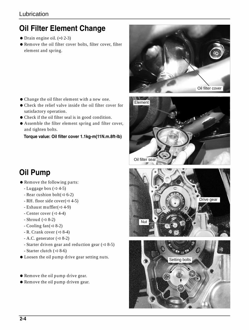
Oil Filter Element ChangeDrain engine oil. ( 2-3)Remove the oil filter cover bolts, filter cover, filter
element and spring.
Change the oil filter element with a new one.Check the relief valve inside the oil filter cover for
satisfactory operation.Check if the oil filter seal is in good condition.Assemble the filter element spring and filter cover,
and tighten bolts.
Torque value: Oil filter cover 1.1kg-m(11N.m.8ft-lb)
Oil PumpRemove the following parts:
- Luggage box (4-5)- Rear cushion bolt(6-2)- RH. floor side cover( 4-5)- Exhaust muffler(4-9)- Center cover (4-4)- Shroud ( 8-2)- Cooling fan( 8-2)- R. Crank cover ( 8-4)- A.C. generator ( 8-2)- Starter driven gear and reduction gear ( 8-5)- Starter clutch ( 8-6)
Loosen the oil pump drive gear setting nuts.
Remove the oil pump drive gear.Remove the oil pump driven gear.
Oil filter cover
Element
Drive gear
Nut
Setting bolts
Oil filter seal
Lubrication
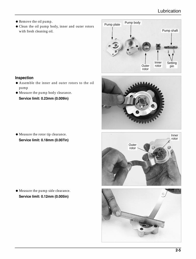
Remove the oil pump.Clean the oil pump body, inner and outer rotors
with fresh cleaning oil.
Measure the rotor tip clearance.
Service limit: 0.18mm (0.007in)
InspectionAssemble the inner and outer rotors to the oil
pumpMeasure the pump body clearance.
Service limit: 0.23mm (0.009in)
Measure the pump side clearance.
Service limit: 0.12mm (0.005in)
2-5
Outer rotor
Innerrotor
Settingpin
Pump shaft
Pump bodyPump plate
Outer rotor
Innerrotor
Lubrication
2-6
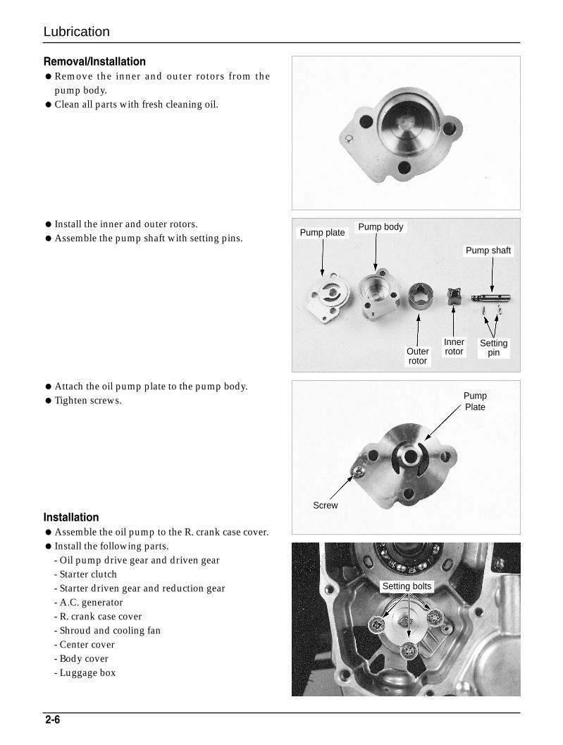
Removal/InstallationRemove the inner and outer rotors from the
pump body.Clean all parts with fresh cleaning oil.
Attach the oil pump plate to the pump body.Tighten screws.
InstallationAssemble the oil pump to the R. crank case cover. Install the following parts.
- Oil pump drive gear and driven gear- Starter clutch- Starter driven gear and reduction gear- A.C. generator- R. crank case cover- Shroud and cooling fan- Center cover- Body cover- Luggage box
Install the inner and outer rotors.Assemble the pump shaft with setting pins.
Screw
PumpPlate
Outer rotor
Innerrotor
Settingpin
Pump shaft
Pump bodyPump plate
Setting bolts
Lubrication
2-7
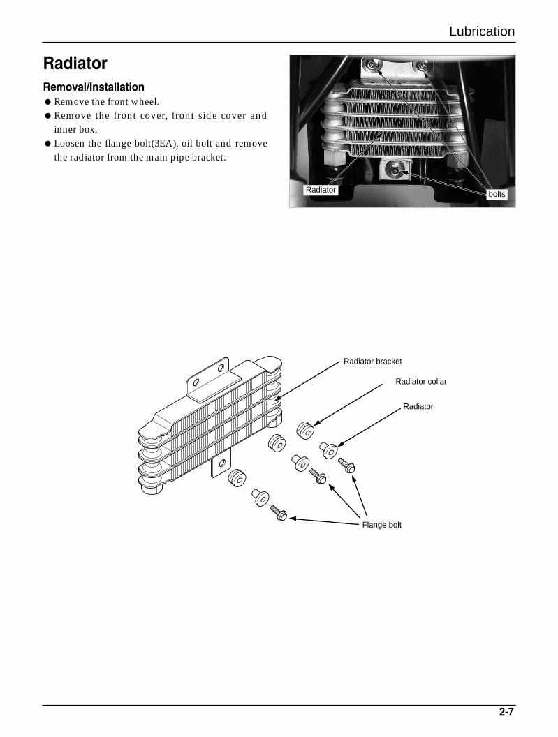
Radiator Removal/InstallationRemove the front wheel. Remove the front cover, front side cover and
inner box.Loosen the flange bolt(3EA), oil bolt and remove
the radiator from the main pipe bracket.
Radiator
Radiator bracket
Radiator collar
Flange bolt
boltsRadiator
Lubrication
2-8
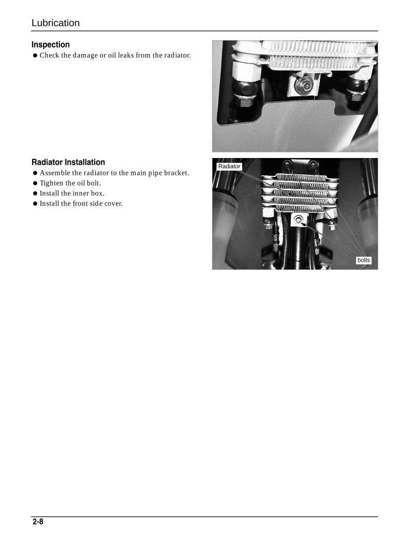
InspectionCheck the damage or oil leaks from the radiator.
Radiator InstallationAssemble the radiator to the main pipe bracket.Tighten the oil bolt. Install the inner box. Install the front side cover.
bolts
Radiator
Lubrication
2-9
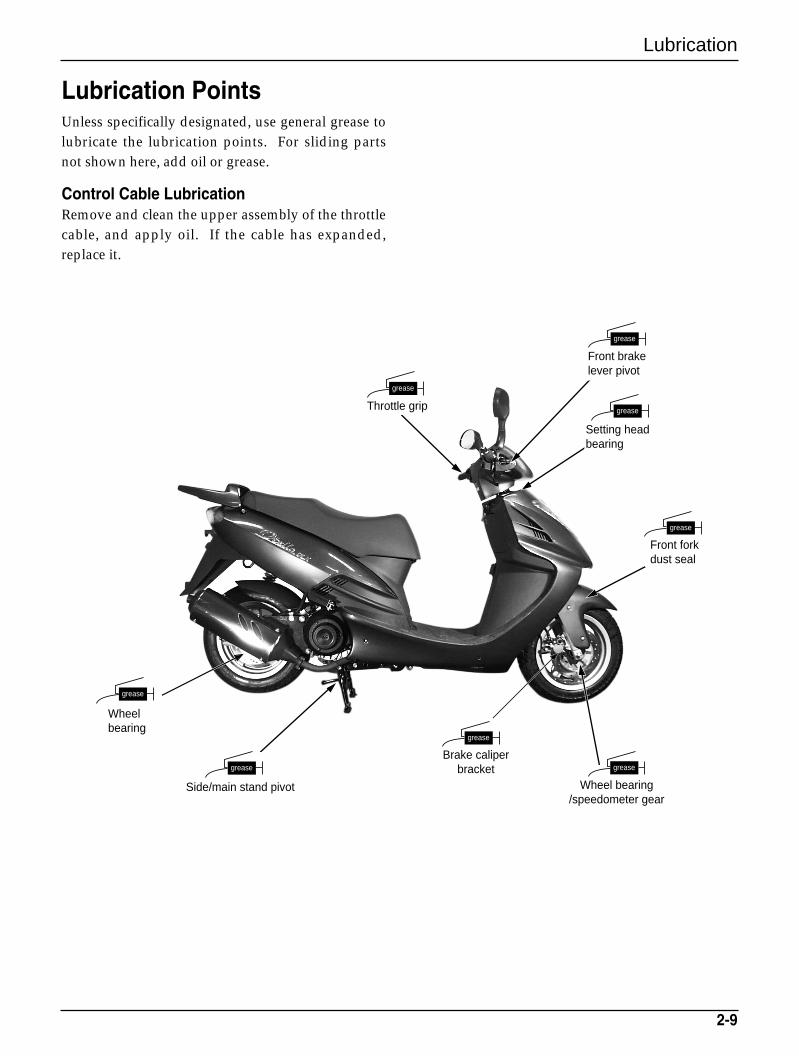
Lubrication PointsUnless specifically designated, use general grease tolubricate the lubrication points. For sliding partsnot shown here, add oil or grease.
Control Cable LubricationRemove and clean the upper assembly of the throttlecable, and apply oil. If the cable has expanded,replace it.
Wheelbearing
Side/main stand pivot
Brake caliper bracket
Wheel bearing/speedometer gear
Front forkdust seal
grease
grease
grease
grease
grease
grease
grease
grease
Front brakelever pivot
Setting headbearing
Throttle grip

MEMO
Inspections/Adjustments
3-1
3. Inspections/Adjustments
Service Information 3-1
Regular Inspection Schedule 3-3
Fuel Line 3-4
Throttle Grip Operation 3-4
Air Cleaner 3-4
Spark Plug 3-5
Valve Tappet Clearance 3-5
Cylinder Compression Pressure 3-6
Carburetor Idling 3-6
Brake Fluid 3-7
Brake Pad 3-7
Brake System 3-7
Brake Lever Free Play 3-8
Headlight Adjustment 3-8
Side Stand 3-8
Suspension 3-9
Bolts and Nuts 3-9
Wheels/Tires 3-9
Steering Head Bearing 3-10
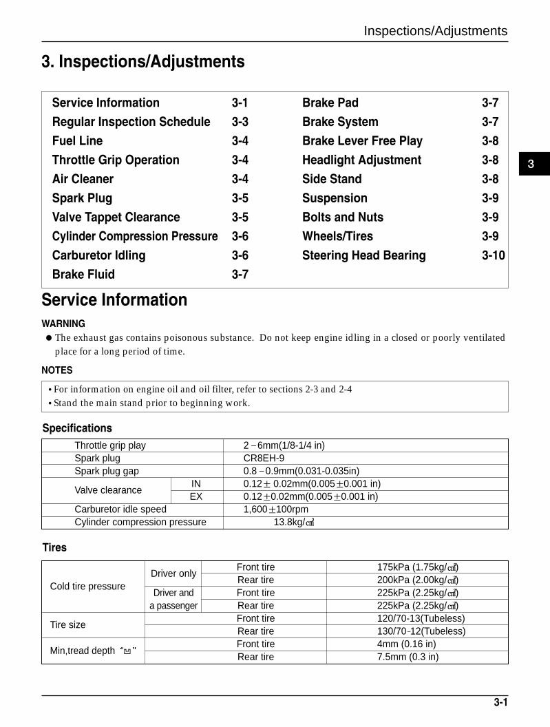
Service InformationWARNINGThe exhaust gas contains poisonous substance. Do not keep engine idling in a closed or poorly ventilated
place for a long period of time.
NOTES
Driver onlyFront tire 175kPa (1.75kg/)Rear tire 200kPa (2.00kg/)
Cold tire pressureDriver and Front tire 225kPa (2.25kg/)
a passenger Rear tire 225kPa (2.25kg/)
Tire sizeFront tire 120/70-13(Tubeless)Rear tire 130/70-12(Tubeless)
Min,tread depthFront tire 4mm (0.16 in)Rear tire 7.5mm (0.3 in)
•For information on engine oil and oil filter, refer to sections 2-3 and 2-4•Stand the main stand prior to beginning work.
Throttle grip play 2–6mm(1/8-1/4 in)Spark plug CR8EH-9Spark plug gap 0.8–0.9mm(0.031-0.035in)
Valve clearanceIN 0.12± 0.02mm(0.005±0.001 in)EX 0.12±0.02mm(0.005±0.001 in)
Carburetor idle speed 1,600±100rpmCylinder compression pressure 13.8kg/
Specifications
Tires
3
3-2
Inspections/Adjustments
Torque ValuesSpark plug 1.1kg–m, (11N.m, 8ft–lb)Cylinder head cover bolts 1.0kg–m, (10N.m, 7ft–lb)Valve adjusting nuts 1.1kg–m, (11N.m, 8ft–lb)Timing hole cap 0.6kg–m, (6N.m, 4.3ft–lb)
ToolsWrench, 8×9mm Adjusting wrenchCompression gauge
* Fuel line(Fuel tube) I I I I
* Fuel filter R R R R
* Throttle grip operation I I I I
Air cleaner C for each 1,000km Note 2
Spark plug I R I
* Valve clearance I I I I
Transmission oil R
Engine oil R R R R** Engine oil filter element R R R R
* Carburetor idle speed I I I I
Brake fluid I I R Note 3
Brake shoe/pad I I I
Brake system I I I I
* Brake stop switch I I I
* Headlight beam distance I I I
Side stand I I I
* Suspension I I I
* Bolt and nut tightness I I
** wheels/tires I I I** Steering head bearing I I
3-3
Inspections/Adjustments
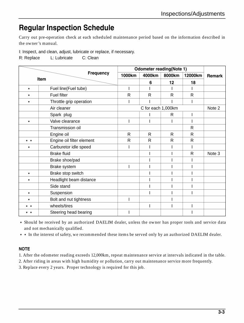
Regular Inspection ScheduleCarry out pre-operation check at each scheduled maintenance period based on the information described inthe owner’s manual.
I: Inspect, and clean, adjust, lubricate or replace, if necessary.R: Replace L: Lubricate C: Clean
FrequencyOdometer reading(Note 1)
Item1000km 4000km 8000km 12000km Remark
6 12 18
* Should be received by an authorized DAELIM dealer, unless the owner has proper tools and service dataand not mechanically qualified.
** In the interest of safety, we recommended these items be served only by an authorized DAELIM dealer.
NOTE1. After the odometer reading exceeds 12,000km, repeat maintenance service at intervals indicated in the table.2. After riding in areas with high humidity or pollution, carry out maintenance service more frequently.3. Replace every 2 years. Proper technology is required for this job.
Inspecitions/Adjustments
3-4
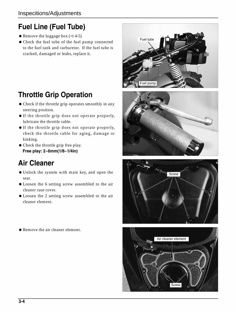
Fuel Line (Fuel Tube)Remove the luggage box ( 4-5)Check the fuel tube of the fuel pump connected
to the fuel tank and carburetor. If the fuel tube iscracked, damaged or leaks, replace it.
Throttle Grip OperationCheck if the throttle grip operates smoothly in any
steering position. If the throttle grip does not operate properly,
lubricate the throttle cable. If the throttle grip does not operate properly,
check the throttle cable for aging, damage orkinking.
Check the throttle grip free play.Free play: 2~6mm(1/8~1/4in)
Air CleanerUnlock the system with main key, and open the
seat.Loosen the 6 setting screw assembled to the air
cleaner case cover.Loosen the 2 setting screw assembled to the air
cleaner element.
Remove the air cleaner element.
Fuel pump
Fuel tube
Screw
Screw
Air cleaner element
3-5
Inspecitions/Adjustments
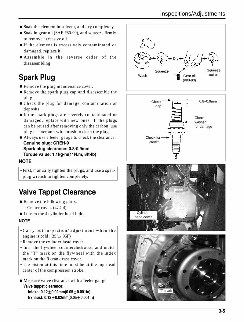
Soak the element in solvent, and dry completely.Soak in gear oil (SAE #80-90), and squeeze firmly
to remove excessive oil. If the element is excessively contaminated or
damaged, replace it.Assemble in the reverse order of the
disassembling.
Spark PlugRemove the plug maintenance cover.Remove the spark plug cap and disassemble the
plug.Check the plug for damage, contamination or
deposits. If the spark plugs are severely contaminated or
damaged, replace with new ones. If the plugscan be reused after removing only the carbon, useplug cleaner and wire brush to clean the plugs.
Always use a feeler gauge to check the clearance.Genuine plug: CREH-9Spark plug clearance: 0.8-0.9mmTorque value: 1.1kg-m(11N.m, 8ft-lb)
NOTE
Valve Tappet ClearanceRemove the following parts.
-- Center cover. (4-4)Loosen the 4 cylinder head bolts.
NOTE
Measure valve clearance with a feeler gauge.Valve tappet clearance:
Intake: 0.12±0.02mm(0.05±0.001in)Exhaust: 0.12±0.02mm(0.05±0.001in)
•Carry out inspection/adjustment when theengine is cold. (35/95F)
•Remove the cylinder head cover.•Turn the flywheel counterclockwise, and match
the “T” mark on the flywheel with the indexmark on the R crank case cover.
•The piston at this time must be at the top deadcenter of the compression stroke.
•First, manually tighten the plugs, and use a sparkplug wrench to tighten completely.
Cylinder head cover
“T” mark
WashSqueeze
Dry
Gear oil(#80-90)
Checkwasherfor damage
Check for cracks.
Checkgap
Squeeze out oil
Oil
0.8~0.9mm
Inspections/Adjustments
3-6
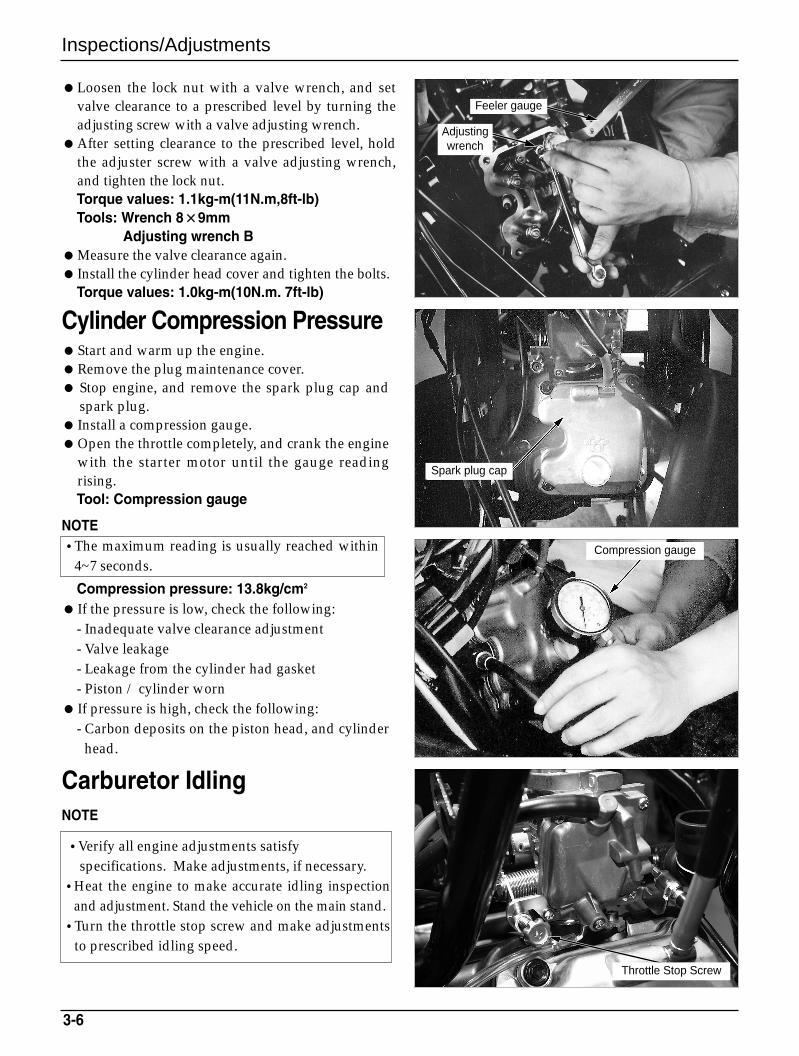
Loosen the lock nut with a valve wrench, and setvalve clearance to a prescribed level by turning theadjusting screw with a valve adjusting wrench.
After setting clearance to the prescribed level, holdthe adjuster screw with a valve adjusting wrench,and tighten the lock nut.Torque values: 1.1kg-m(11N.m,8ft-lb)Tools: Wrench 8××9mm
Adjusting wrench BMeasure the valve clearance again. Install the cylinder head cover and tighten the bolts.
Torque values: 1.0kg-m(10N.m. 7ft-lb)
Cylinder Compression PressureStart and warm up the engine.Remove the plug maintenance cover. Stop engine, and remove the spark plug cap and
spark plug. Install a compression gauge.Open the throttle completely, and crank the engine
with the starter motor until the gauge readingrising.Tool: Compression gauge
NOTE
Compression pressure: 13.8kg/cm2
If the pressure is low, check the following:- Inadequate valve clearance adjustment - Valve leakage- Leakage from the cylinder had gasket- Piston / cylinder worn
If pressure is high, check the following:- Carbon deposits on the piston head, and cylinder
head.
Carburetor IdlingNOTE
•The maximum reading is usually reached within4~7 seconds.
•Verify all engine adjustments satisfyspecifications. Make adjustments, if necessary.
•Heat the engine to make accurate idling inspectionand adjustment. Stand the vehicle on the main stand.
•Turn the throttle stop screw and make adjustmentsto prescribed idling speed.
Feeler gauge
Adjustingwrench
Spark plug cap
Compression gauge
Throttle Stop Screw
3-7
Inspecitions/Adjustments
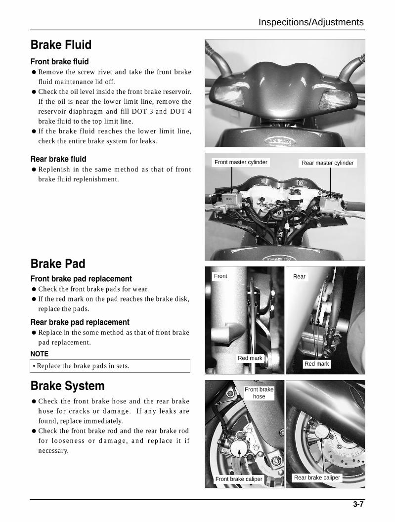
Brake FluidFront brake fluidRemove the screw rivet and take the front brake
fluid maintenance lid off.Check the oil level inside the front brake reservoir.
If the oil is near the lower limit line, remove thereservoir diaphragm and fill DOT 3 and DOT 4brake fluid to the top limit line.
If the brake fluid reaches the lower limit line,check the entire brake system for leaks.
Brake PadFront brake pad replacementCheck the front brake pads for wear. If the red mark on the pad reaches the brake disk,
replace the pads.
Rear brake pad replacementReplace in the some method as that of front brake
pad replacement.
NOTE
Rear brake fluid Replenish in the same method as that of front
brake fluid replenishment.
Brake SystemCheck the front brake hose and the rear brake
hose for cracks or damage. If any leaks arefound, replace immediately.
Check the front brake rod and the rear brake rodfor looseness or damage, and replace it ifnecessary.
•Replace the brake pads in sets.
Front master cylinder
Front
Red mark
Front brakehose
Front brake caliper Rear brake caliper
Red mark
Rear master cylinder
Rear
Inspections/Adjustments
3-8
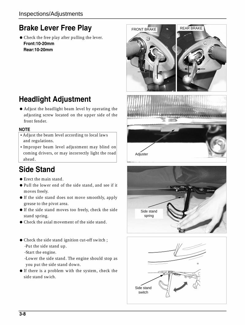
Brake Lever Free PlayCheck the free play after pulling the lever.
Front:10-20mmRear:10-20mm
Check the side stand ignition cut-off switch ;-Put the side stand up.-Start the engine.-Lower the side stand. The engine should stop asyou put the side stand down.
If there is a problem with the system, check theside stand swich.
Headlight AdjustmentAdjust the headlight beam level by operating the
adjusting screw located on the upper side of thefront fender.
NOTE
Side StandErect the main stand.Pull the lower end of the side stand, and see if it
moves freely. If the side stand does not move smoothly, apply
grease to the pivot area. If the side stand moves too freely, check the side
stand spring.Check the axial movement of the side stand.
•Adjust the beam level according to local lawsand regulations.
•Improper beam level adjustment may blind oncoming drivers, or may incorrectly light the roadahead.
Side standspring
Side standswitch
Adjuster
FRONT BRAKE REAR BRAKE
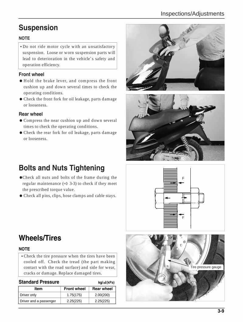
Wheels/TiresNOTE
3-9
Item Front wheel Rear wheel
Driver only 1.75(175) 2.00(200)
Driver and a passenger 2.25(225) 2.25(225)
Standard Pressure kg/(kPa)
•Check the tire pressure when the tires have beencooled off. Check the tread (the part makingcontact with the road surface) and side for wear,cracks or damage. Replace damaged tires.
SuspensionNOTE
Front wheelHold the brake lever, and compress the front
cushion up and down several times to check theoperating conditions.
Check the front fork for oil leakage, parts damageor looseness.
Rear wheelCompress the near cushion up and down several
times to check the operating conditions.Check the rear fork for oil leakage, parts damage
or looseness.
Bolts and Nuts TighteningCheck all nuts and bolts of the frame during the
regular maintenance ( 3-3) to check if they meetthe prescribed torque value.
Check all pins, clips, hose clamps and cable stays.
Inspections/Adjustments
•Do not ride motor cycle with an unsatisfactorysuspension. Loose or worn suspension parts willlead to deterioration in the vehicle’s safety andoperation efficiency.
Tire pressure gauge
F
F
Inspections/Adjustments
3-10
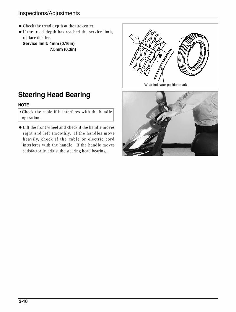
Check the tread depth at the tire center. If the tread depth has reached the service limit,
replace the tire.Service limit: 4mm (0.16in)
7.5mm (0.3in)
Steering Head BearingNOTE
Lift the front wheel and check if the handle movesright and left smoothly. If the handles moveheavily, check if the cable or electric cordinterferes with the handle. If the handle movessatisfactorily, adjust the steering head bearing.
•Check the cable if it interferes with the handleoperation.
Wear indicator position mark
External Parts
4-1
4. External Parts
Service InformationNOTEThis section describes external parts removal/installation.Do not apply unreasonable force when disassembling covers, to prevent possible damage.A muffler is hot. Do not service it immediately after the engine is stopped.
Service Information 4-1
Maintenance Procedure 4-2
External Parts Removal/Installation 4-3
Muffler 4-9
Front Fender 4-10
4
External Parts
4-2
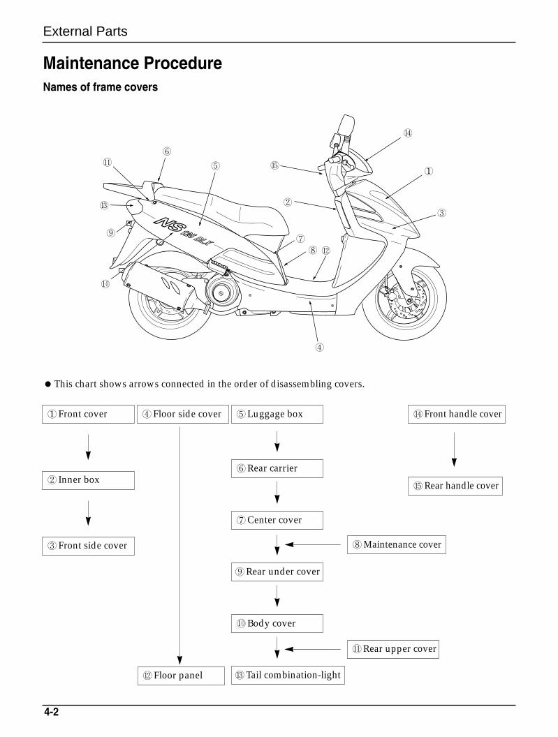
This chart shows arrows connected in the order of disassembling covers.
①Front cover
② Inner box
③Front side cover
④Floor side cover
⑧Maintenance cover
⑦Center cover
⑨Rear under cover
⑮Rear handle cover
⑩Body cover
⑫Floor panel
⑭Front handle cover⑤Luggage box
⑥Rear carrier
⑬Tail combination-light
⑪Rear upper cover
Maintenance ProcedureNames of frame covers
①
⑭
③
④
②
⑮
⑦⑧ ⑫
⑤
⑥⑪
⑨
⑬
⑩
External Parts
4-3
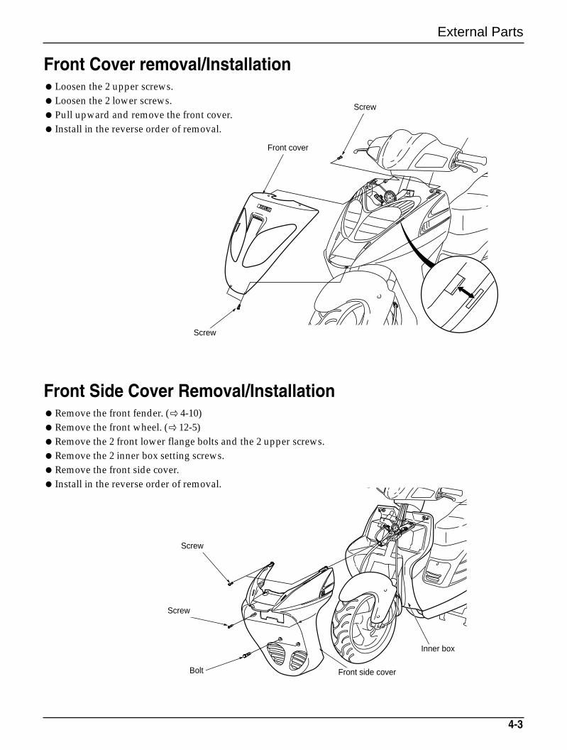
Front Cover removal/InstallationLoosen the 2 upper screws.Loosen the 2 lower screws.Pull upward and remove the front cover. Install in the reverse order of removal.
Front Side Cover Removal/InstallationRemove the front fender. ( 4-10)Remove the front wheel. ( 12-5)Remove the 2 front lower flange bolts and the 2 upper screws.Remove the 2 inner box setting screws.Remove the front side cover. Install in the reverse order of removal.
Screw
Front cover
Screw
Inner box
Front side coverBolt
Screw
Screw
External Parts
4-4
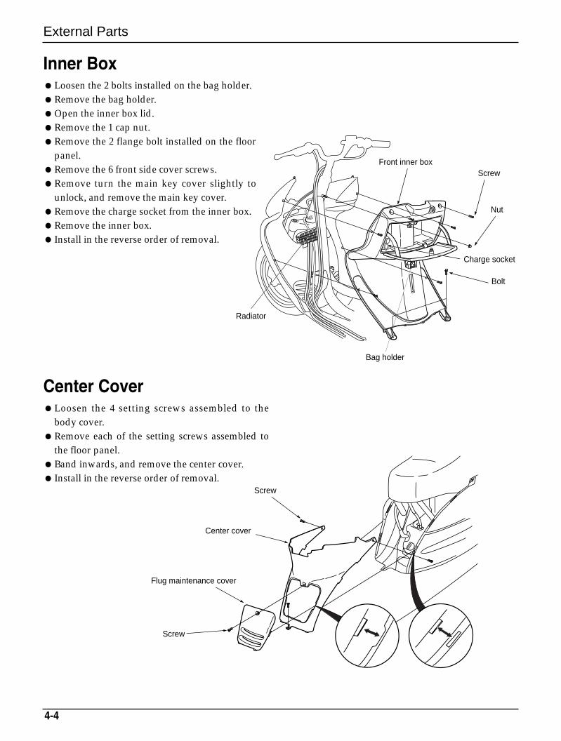
Inner BoxLoosen the 2 bolts installed on the bag holder.Remove the bag holder.Open the inner box lid.Remove the 1 cap nut.Remove the 2 flange bolt installed on the floor
panel.Remove the 6 front side cover screws.Remove turn the main key cover slightly to
unlock, and remove the main key cover.Remove the charge socket from the inner box.Remove the inner box. Install in the reverse order of removal.
Center CoverLoosen the 4 setting screws assembled to the
body cover.Remove each of the setting screws assembled to
the floor panel.Band inwards, and remove the center cover. Install in the reverse order of removal.
ScrewFront inner box
Nut
Bolt
Charge socket
Bag holder
Radiator
Screw
Center cover
Screw
Flug maintenance cover
4-5
External Parts
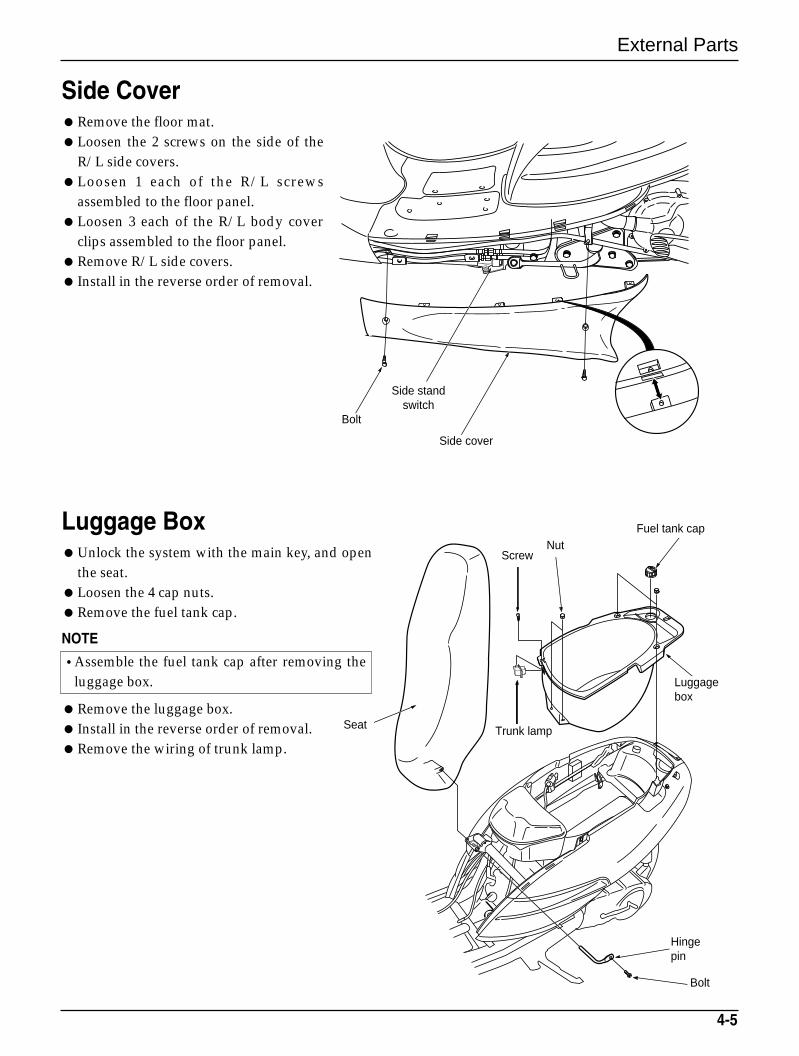
Side CoverRemove the floor mat.Loosen the 2 screws on the side of the
R/L side covers.Loosen 1 each of the R/L screws
assembled to the floor panel.Loosen 3 each of the R/L body cover
clips assembled to the floor panel.Remove R/L side covers. Install in the reverse order of removal.
Luggage BoxUnlock the system with the main key, and open
the seat.Loosen the 4 cap nuts.Remove the fuel tank cap.
NOTE
Remove the luggage box. Install in the reverse order of removal.Remove the wiring of trunk lamp.
Side cover
Side standswitch
Seat
Fuel tank cap
Luggage box
NutScrew
Trunk lamp
Hingepin
Bolt
Bolt
•Assemble the fuel tank cap after removing theluggage box.
External Parts
4-6
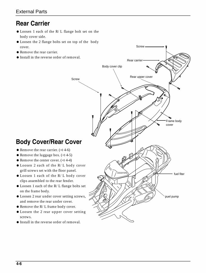
Rear CarrierLoosen 1 each of the R/L flange bolt set on the
body cover side.Loosen the 2 flange bolts set on top of the body
cover.Remove the rear carrier. Install in the reverse order of removal.
Body Cover/Rear CoverRemove the rear carrier. ( 4-6)Remove the luggage box. (4-5)Remove the center cover. (4-4)Loosen 2 each of the R/L body cover
grill screws set with the floor panel.Loosen 1 each of the R/L body cover
clips assembled to the rear fender.Loosen 1 each of the R/L flange bolts set
on the frame body.Loosen 2 rear under cover setting screws,
and remove the rear under cover.Remove the R/L frame body cover.Loosen the 2 rear upper cover setting
screws. Install in the reverse order of removal.
Screw
Body cover clip
Rear upper cover
Frame bodycover
fuel fiter
puel pump
Rear carrier
Screw
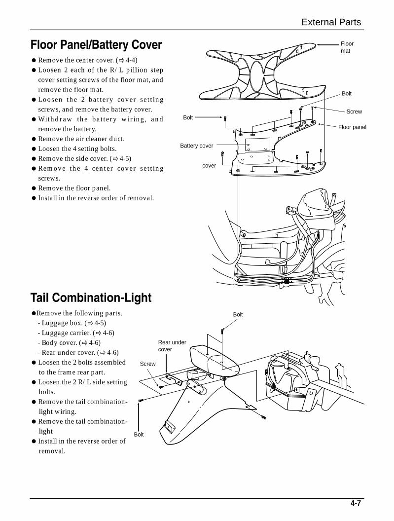
Tail Combination-LightRemove the following parts.
- Luggage box. ( 4-5)- Luggage carrier. ( 4-6)- Body cover. ( 4-6)- Rear under cover. ( 4-6)
Loosen the 2 bolts assembled to the frame rear part.
Loosen the 2 R/L side setting bolts.
Remove the tail combination-light wiring.
Remove the tail combination-light
Install in the reverse order of removal.
4-7
External Parts
Floor Panel/Battery CoverRemove the center cover. ( 4-4)Loosen 2 each of the R/L pillion step
cover setting screws of the floor mat, andremove the floor mat.
Loosen the 2 battery cover settingscrews, and remove the battery cover.
Withdraw the battery wiring, andremove the battery.
Remove the air cleaner duct.Loosen the 4 setting bolts.Remove the side cover. ( 4-5)Remove the 4 center cover setting
screws.Remove the floor panel. Install in the reverse order of removal.
Floor mat
Screw
Floor panel
Bolt
Bolt
Bolt
Rear under cover
Screw
Bolt
Battery cover
cover
External Parts
4-8
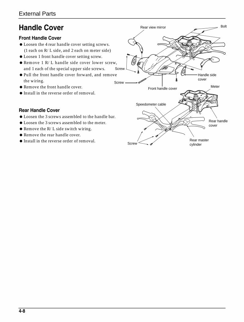
Handle CoverFront Handle CoverLoosen the 4 rear handle cover setting screws.
(1 each on R/L side, and 2 each on meter side)Loosen 1 front handle cover setting screw.Remove 1 R/L handle side cover lower screw,
and 1 each of the special upper side screws.Pull the front handle cover forward, and remove
the wiring.Remove the front handle cover. Install in the reverse order of removal.
Rear Handle CoverLoosen the 3 screws assembled to the handle bar.Loosen the 3 screws assembled to the meter.Remove the R/L side switch wiring.Remove the rear handle cover. Install in the reverse order of removal.
Rear view mirror Bolt
Screw
Screw
Front handle cover
Handle sidecover
Meter
Rear handlecover
Rear mastercylinder
Speedometer cable
Screw
4-9
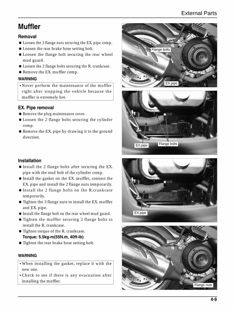
Muffler RemovalLoosen the 3 flange nuts securing the EX. pipe comp.Loosen the rear brake hose setting bolt.Loosen the flange bolt securing the rear wheel
mud guard.Loosen the 2 flange bolts securing the R. crankcase.Remove the EX. muffler comp.
WARNING
EX. Pipe removalRemove the plug maintenance cover.Loosen the 2 flange bolts securing the cylinder
comp.Remove the EX. pipe by drawing it to the ground
direction.
Installation Install the 2 flange bolts after securing the EX.
pipe with the stud bolt of the cylinder comp. Install the gasket on the EX. muffler, connect the
EX. pipe and install the 2 flange nuts temporarily. Install the 2 flange bolts on the R.crankcase
temporarily.Tighten the 3 flange nuts to install the EX. muffler
and EX. pipe. Install the flange bolt on the rear wheel mud guard.Tighten the muffler securing 2 flange bolts to
install the R. crankcase.Tighten torque of the R. crankcase.
Torque: 5.5kg-m(55N.m, 40ft-lb)Tighten the rear brake hose setting bolt.
WARNING
External Parts
•Never perform the maintenance of the mufflerright after stopping the vehicle because themuffler is extremely hot.
•When installing the gasket, replace it with thenew one.
•Check to see if there is any evacuation afterinstalling the muffler.
Flange bolts
Flange bolts
Flange nuts
EX.pipe
EX.pipe
EX.pipe
External Parts
4-10
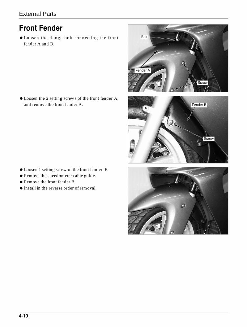
Front FenderLoosen the flange bolt connecting the front
fender A and B.
Loosen the 2 setting screws of the front fender A,and remove the front fender A.
Loosen 1 setting screw of the front fender B.Remove the speedometer cable guide.Remove the front fender B. Install in the reverse order of removal.
Fender B
Screw
Screw
Fender A
Bolt
MEMO
Fuel System
5-0
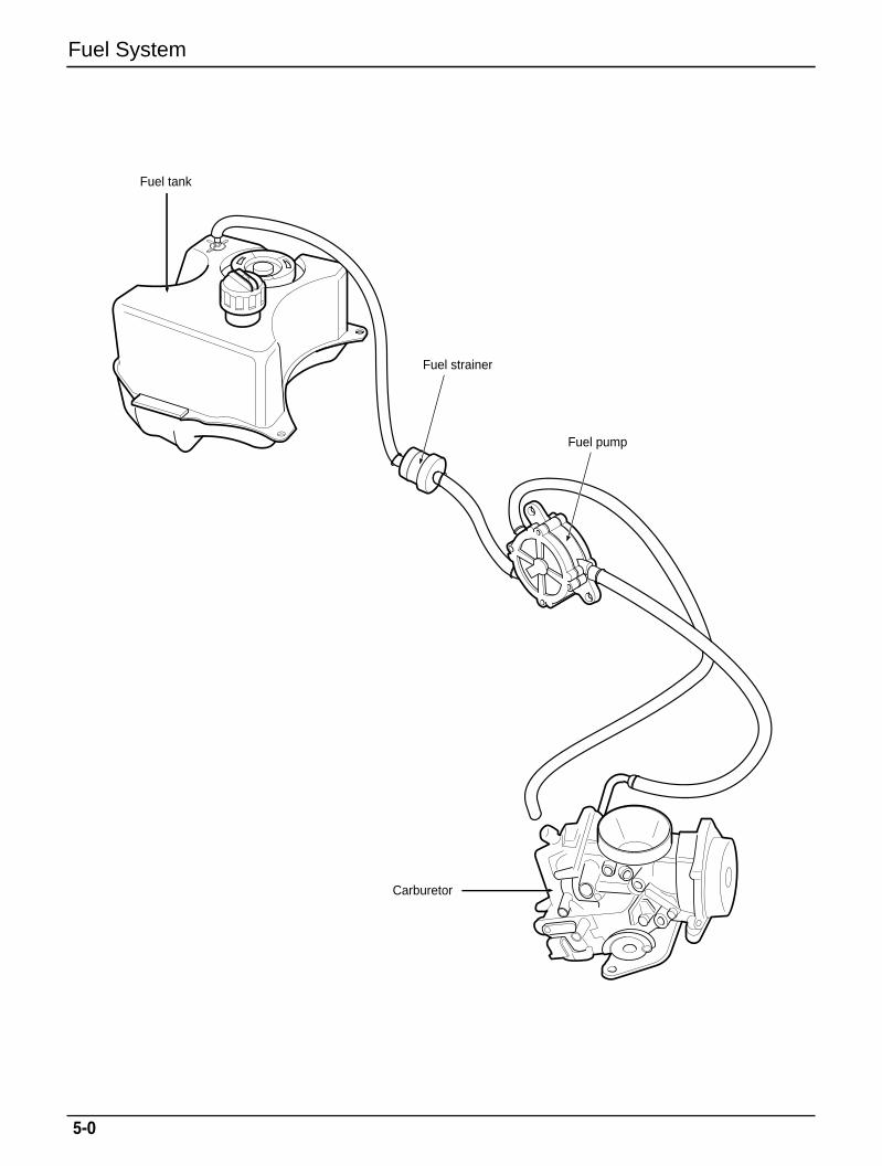
Fuel tank
Fuel strainer
Fuel pump
Carburetor
Fuel System
5-1
5. Fuel System
Service Information 5-1
Troubleshooting 5-2Fuel Tank 5-3
Air Cleaner Removal 5-4
Carburetor 5-4
Pilot Screw Adjustment 5-9
Fuel Pump Inspection 5-9
Service InformationGeneral SafetyWARNINGGasoline is extremely flammable. Avoid fire in the work place, also paying particular attention to sparks.
Furthermore, the evaporated (gasified) gasoline is highly explosive. Work in a well-ventilated areas.Exhaust gas contains poisonous substance. Do not keep engine running for a long period of time in a
closed, or poorly ventilated area.
CAUTIONDo not excessively bend or twist cable. Distorted or damaged cable may lead to mechanical malfunctions.Pay particular attention to the position of O-ring. Replace with new ones when disassembled. If it is desired to store a vehicle for a period longer than 1 month, drain gasoline out of the carburetor float
chamber. Gasoline left in the float chamber will be deteriorated causing the slow jet to be clogged withdeposits, and idling may become unstable.
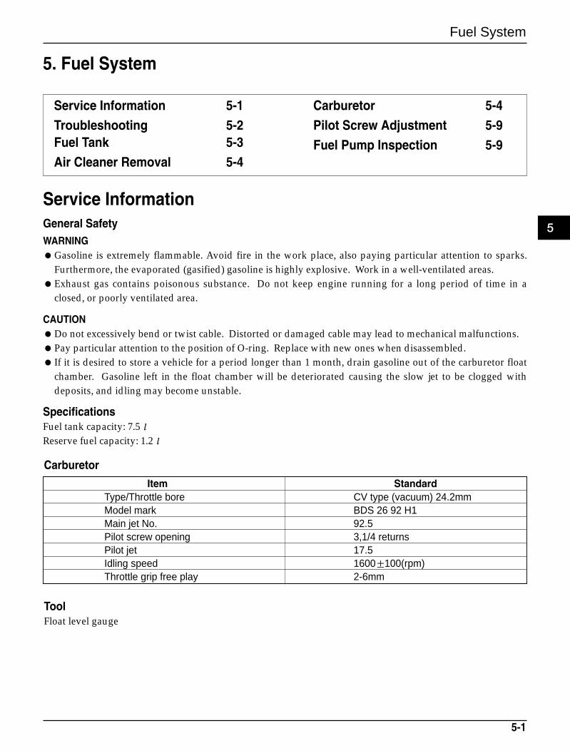
SpecificationsFuel tank capacity: 7.5ℓReserve fuel capacity: 1.2ℓ
Item StandardType/Throttle bore CV type (vacuum) 24.2mmModel mark BDS 26 92 H1Main jet No. 92.5Pilot screw opening 3,1/4 returnsPilot jet 17.5Idling speed 1600±100(rpm)Throttle grip free play 2-6mm
ToolFloat level gauge
Carburetor
5
Fuel System
5-2
TroubleshootingUnable to start the engineNo fuel in the tank.Fuel cannot be supplied.Fuel excessively absorbed into the cylinder.Air cleaner clogged.No spark from plugs.
Unstable idling, unsatisfactory rotationUnsatisfactory idling adjustment.Mixture too lean or richAir cleaner clogged.Secondary air absorbed into the intake system.Fuel system clogged.
Mixture too leanCarburetor jets clogged.Fuel tank cap air hole clogged.Fuel strainer screen clogged.Fuel tube kinked, pressed or clogged.Float valve malfunction.Oil level too low.
Mixture too richFloat valve malfunction.Oil level too high.Air jets clogged.
Fuel System
Fuel TankRemoveWARNING
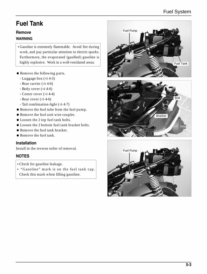
Remove the following parts.- Luggage box ( 4-5)- Rear carrier ( 4-6)- Body cover (4-6)- Center cover ( 4-4)- Rear cover ( 4-6)- Tail combination-light ( 4-7)
Remove the fuel tube from the fuel pump.Remove the fuel unit wire coupler.Loosen the 2 top fuel tank bolts.Loosen the 2 bottom fuel tank bracket bolts.Remove the fuel tank bracket.Remove the fuel tank.
InstallationInstall in the reverse order of removal.
NOTES
5-3
•Check for gasoline leakage.• “Gasoline” mark is on the fuel tank cap.
Check this mark when filling gasoline.
•Gasoline is extremely flammable. Avoid fire duringwork, and pay particular attention to electric sparks.Furthermore, the evaporated (gasified) gasoline ishighly explosive. Work in a well-ventilated areas.
Fuel Pump
Fuel Pump
Bracket
Bolt
Fuel Tank
Fuel System
5-4
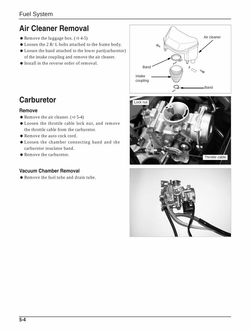
Air Cleaner RemovalRemove the luggage box. (4-5)Loosen the 2 R/L bolts attached to the frame body.Loosen the band attached to the lower part(carburetor)
of the intake coupling and remove the air cleaner. Install in the reverse order of removal.
CarburetorRemoveRemove the air cleaner. ( 5-4)Loosen the throttle cable lock nut, and remove
the throttle cable from the carburetor.Remove the auto cock cord.Loosen the chamber connecting band and the
carburetor insulator band.Remove the carburetor.
Vacuum Chamber RemovalRemove the fuel tube and drain tube.
Air cleaner
Band
Intakecoupling
Band
Lock nut
Throttle cable
Fuel System
5-5
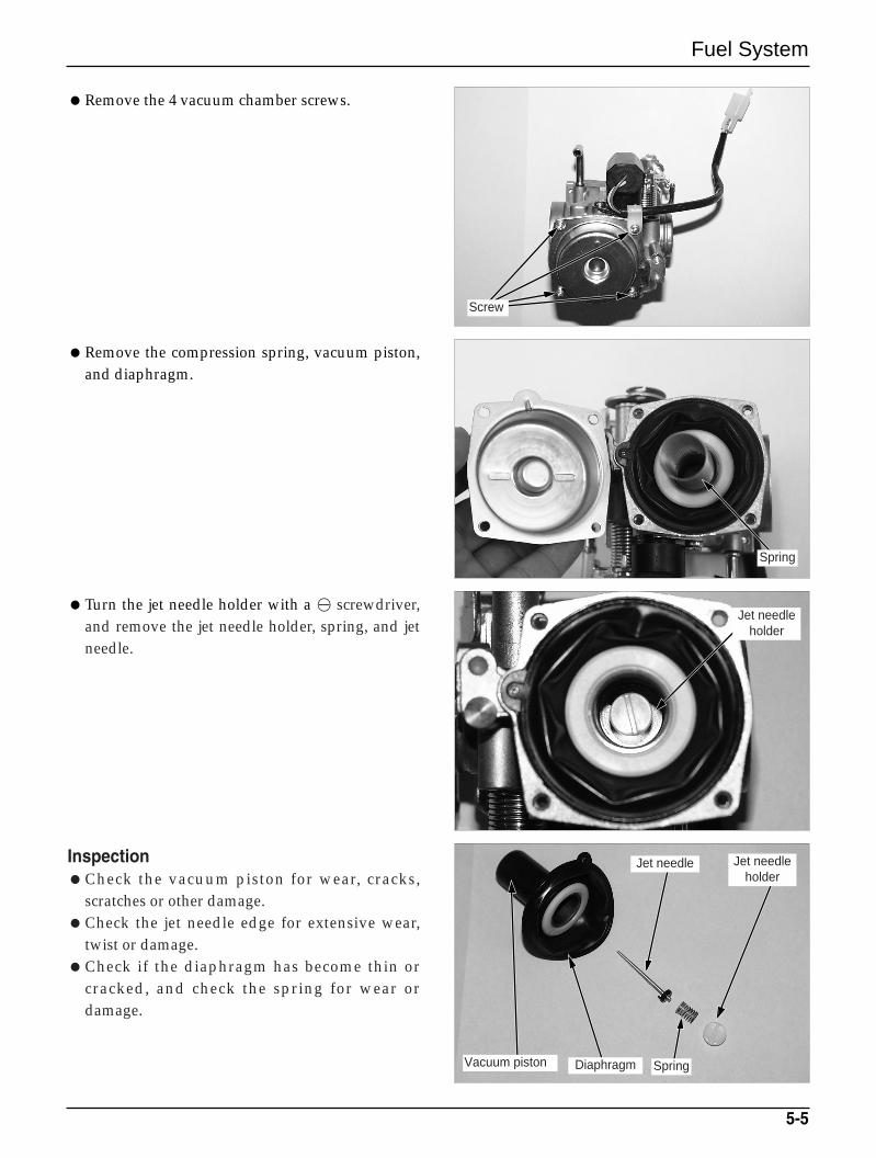
Remove the compression spring, vacuum piston,and diaphragm.
Remove the 4 vacuum chamber screws.
Turn the jet needle holder with a ⊖ screwdriver,and remove the jet needle holder, spring, and jetneedle.
InspectionCheck the vacuum piston for wear, cracks,
scratches or other damage.Check the jet needle edge for extensive wear,
twist or damage.Check if the diaphragm has become thin or
cracked, and check the spring for wear ordamage.
Spring
Screw
Jet needleholder
SpringDiaphragmVacuum piston
Jet needle
Jet needleholder
Fuel System
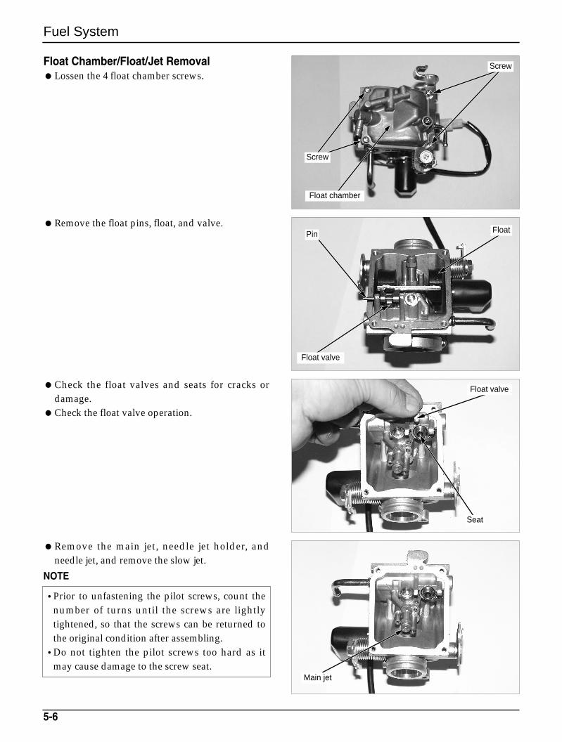
Float Chamber/Float/Jet RemovalLossen the 4 float chamber screws.
Remove the float pins, float, and valve.
5-6
Screw
Screw
Float chamber
Pin Float
Float valve
Check the float valves and seats for cracks ordamage.
Check the float valve operation.
Remove the main jet, needle jet holder, andneedle jet, and remove the slow jet.
NOTE
•Prior to unfastening the pilot screws, count thenumber of turns until the screws are lightlytightened, so that the screws can be returned tothe original condition after assembling.
•Do not tighten the pilot screws too hard as itmay cause damage to the screw seat.
Main jet
Float valve
Seat
Fuel System
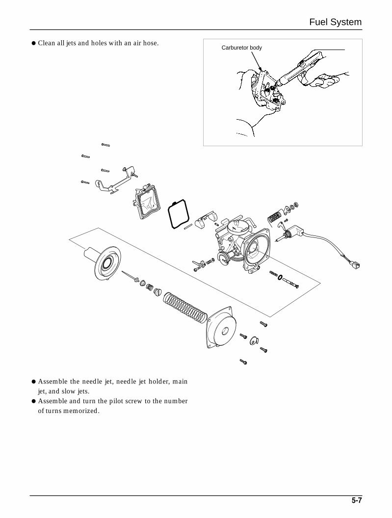
Clean all jets and holes with an air hose.
5-7
Assemble the needle jet, needle jet holder, mainjet, and slow jets.
Assemble and turn the pilot screw to the numberof turns memorized.
Carburetor body
Fuel System
5-8
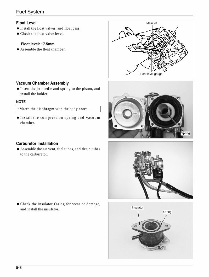
Float Level Install the float valves, and float pins.Check the float valve level.
Float level: 17.5mmAssemble the float chamber.
Vacuum Chamber Assembly Insert the jet needle and spring to the piston, and
install the holder.
NOTE
Install the compression spring and vacuumchamber.
Carburetor InstallationAssemble the air vent, fuel tubes, and drain tubes
to the carburetor.
•Match the diaphragm with the body notch.
Check the insulator O-ring for wear or damage,and install the insulator. Insulator
O-ring
Main jet
Float level gauge
Spring
Fuel Pump InspectionNOTE
Start the engine and keep in the idling state. Fuel pump is considered as satisfactory if
dispensing volume of more than 28cc in 10seconds is obtained after disconnecting fuelpump from caburetor and dispensing fuel over 5seconds.
If specified dispensing volume cannot beobtained, check fuel tube, negative pressure tubefuel strainer. If there is no abnormality, replace fuel pumpwith assy.
Fuel System
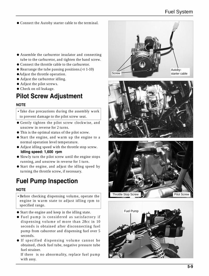
Connect the Autoby starter cable to the terminal.
Assemble the carburetor insulator and connectingtube to the carburetor, and tighten the band screw.
Connect the throttle cable to the carburetor.Rearrange the tube passing positions.(1-10)Adjust the throttle operation.Adjust the carburetor idling.Adjust the pilot screws.Check on oil leakage.
Pilot Screw Adjustment NOTE
Gently tighten the pilot screw clockwise, andunscrew in reverse for 2 turns.
This is the optimal status of the pilot screw.Start the engine, and warm up the engine to a
normal operation level temperature. Adjust idling speed with the throttle stop screw.
Idling speed: 1,600 rpmSlowly turn the pilot screw until the engine stops
running, and unscrew in reverse for 1 turn.Start the engine, and adjust the idling speed by
turning the throttle screw, if necessary.
5-9
•Take due precautions during the assembly workto prevent damage to the pilot screw seat.
•Before checking dispensing volume, operate theengine in warm state to adjust idling rpm tospecified range.
ScrewAutoby-starter cable
Throttle Stop Screw Pilot Screw
Fuel Pump

MEMO
Engine Removal
6-1
6. Engine Removal
Service Information 6-1
Engine Removal 6-2
Service InformationGeneral SafetyNOTE
The following works can be carried out without removing the engine from the vehicle body.- Transmission (Section 11)- A.C. generator (Section 8)- Kick starter, continuously variable transmission(Section 7)- Cylinder head, cylinder, and piston (Section 9 and 10)- Carburetor (Section 5)- Oil pump (Section 2)
Items to be worked after removing engine- Crankshaft, crankshaft bearing, crank case bearing
Engine oil capacity: 1.0ℓ-when disassembled
Torque values:Engine hanger bolt (Front): 2.7kg-m(27N.m, 20ft-1b)
(Rear) : 3.5kg-m(35N.m, 25ft-1b)
•Use a jack to remove or install the engine. Support the motorcycle with a jack firmly, taking precautionsnot to damage the frame, engine, cable or harness.
•Attach tape to the frame to protect it during the engine removal or installation.6
Engine Removal
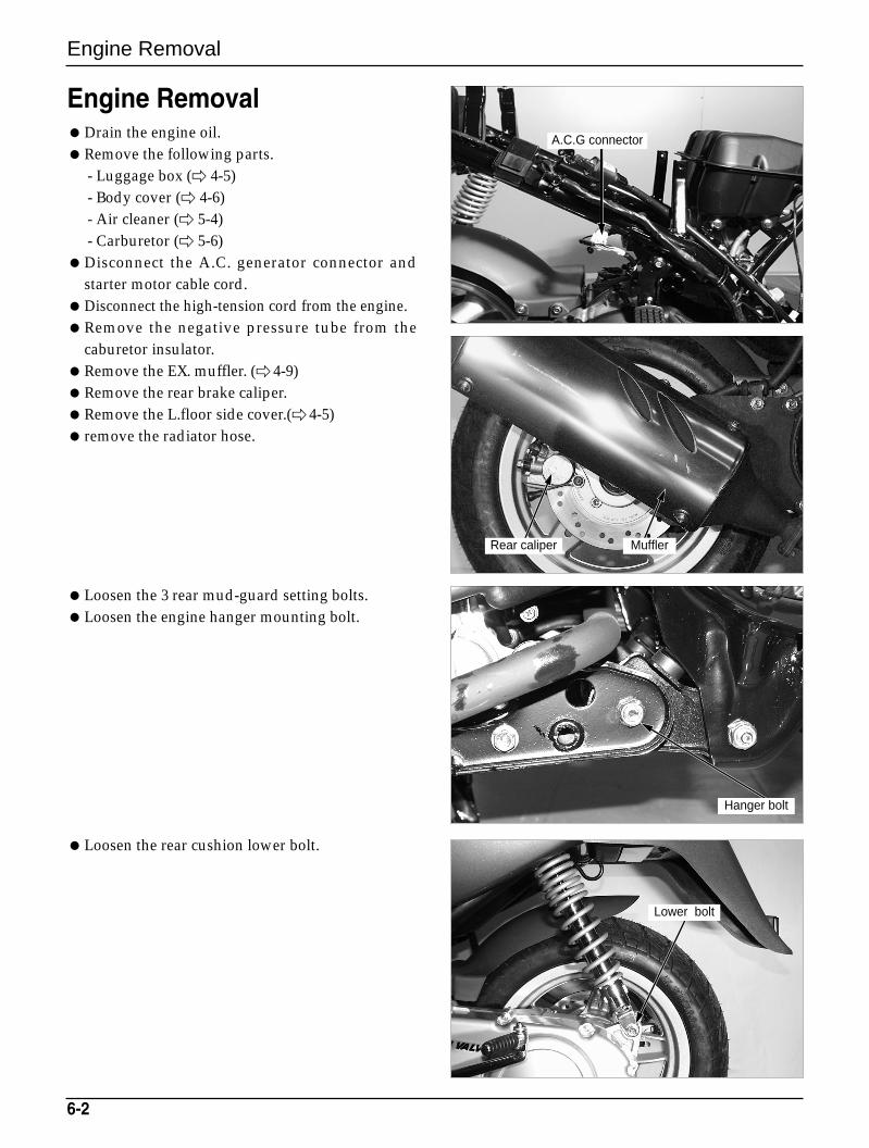
Engine RemovalDrain the engine oil.Remove the following parts.
- Luggage box ( 4-5)- Body cover ( 4-6)- Air cleaner ( 5-4)- Carburetor ( 5-6)
Disconnect the A.C. generator connector andstarter motor cable cord.
Disconnect the high-tension cord from the engine.Remove the negative pressure tube from the
caburetor insulator.Remove the EX. muffler. (4-9)Remove the rear brake caliper.Remove the L.floor side cover.( 4-5) remove the radiator hose.
Loosen the 3 rear mud-guard setting bolts.Loosen the engine hanger mounting bolt.
Loosen the rear cushion lower bolt.
6-2
A.C.G connector
Rear caliper Muffler
Hanger bolt
Lower bolt
Engine Removal
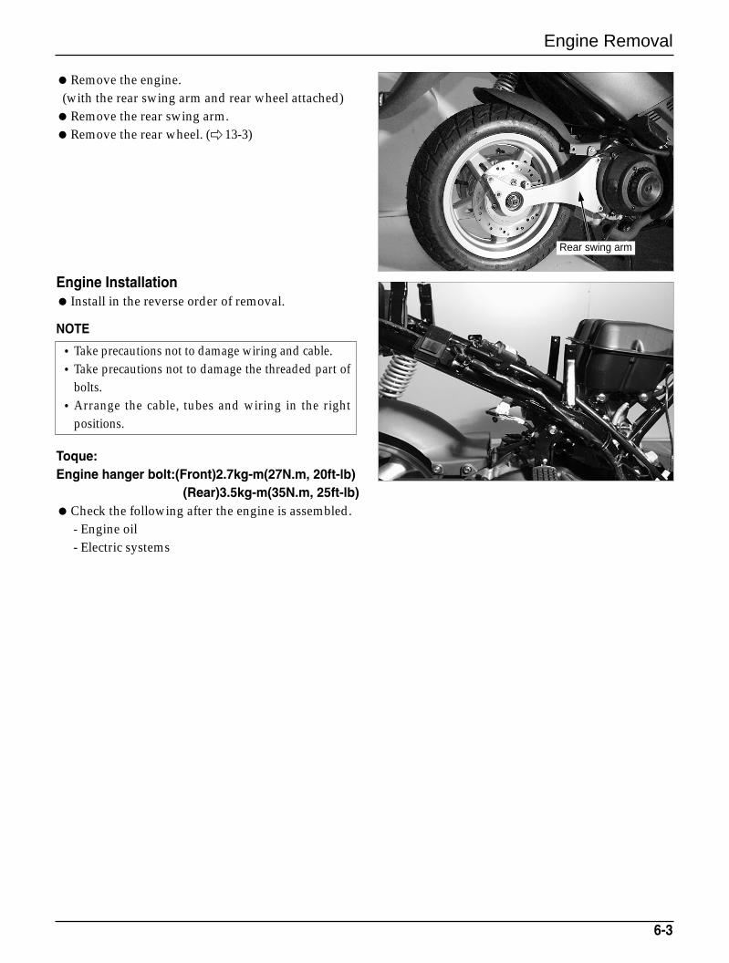
Remove the engine.(with the rear swing arm and rear wheel attached)Remove the rear swing arm. Remove the rear wheel. ( 13-3)
Engine Installation Install in the reverse order of removal.
NOTE
Toque:Engine hanger bolt:(Front)2.7kg-m(27N.m, 20ft-lb)
(Rear)3.5kg-m(35N.m, 25ft-lb)Check the following after the engine is assembled.
- Engine oil- Electric systems
6-3
•Take precautions not to damage wiring and cable.•Take precautions not to damage the threaded part of
bolts.•Arrange the cable, tubes and wiring in the right
positions.
Rear swing arm
L. Crank Case Cover/Kick Starter/Continuously Variable Transmission
7-0
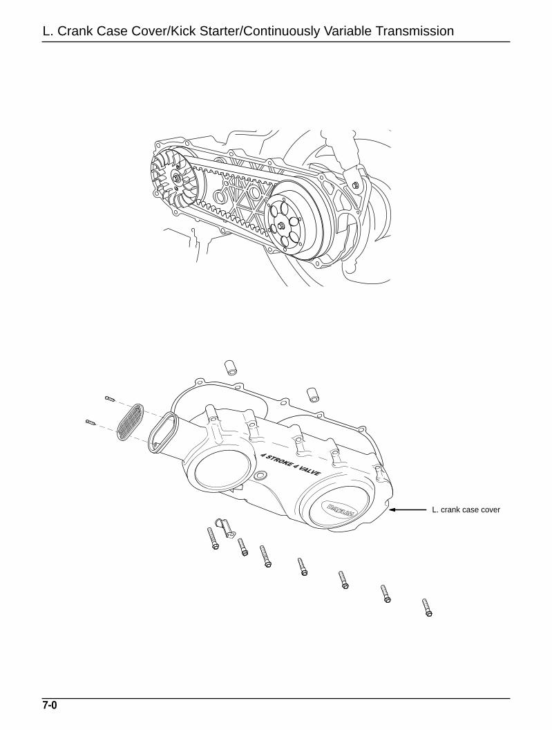
L. crank case cover
L. Crank Case Cover/Kick Starter/Continuously Variable Transmission
7. L. Crank Case Cover/Kick Starter/Continuously variable transmission
7-1
Service Information 7-1Troubleshooting 7-1L. Crank Case Cover 7-2Kick Starter 7-4
Drive Belt 7-7Movable Drive Face 7-9Clutch/Disassembly 7-12Driven Face Disassembly 7-12
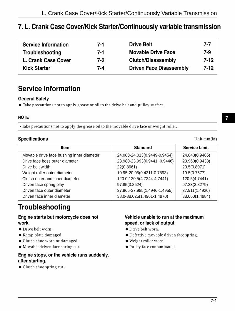
Service InformationGeneral SafetyTake precautions not to apply grease or oil to the drive belt and pulley surface.
•Take precautions not to apply the grease oil to the movable drive face or weight roller.
Specifications
Item Standard Service Limit
Movable drive face bushing inner diameter 24.000-24.013(0.9449-0.9454) 24.040(0.9465)Drive face boss outer diameter 23.980-23.993(0.9441~0.9446) 23.960(0.9433)Drive belt width 22(0.8661) 20.5(0.8071)Weight roller outer diameter 10.95-20.05(0.4311-0.7893) 19.5(0.7677)Clutch outer and inner diameter 120.0-120.5(4.7244-4.7441) 120.5(4.7441)Driven face spring play 97.85(3.8524) 97.23(3.8279)Driven face outer diameter 37.965-37.985(1.4946-1.4955) 37.911(1.4926)Driven face inner diameter 38.0-38.025(1.4961-1.4970) 38.060(1.4984)
TroubleshootingEngine starts but motorcycle does notwork.Drive belt worn.Ramp plate damaged.Clutch shoe worn or damaged.Movable driven face spring cut.
Engine stops, or the vehicle runs suddenly,after starting.Clutch shoe spring cut.
Vehicle unable to run at the maximumspeed, or lack of outputDrive belt worn.Defective movable driven face spring.Weight roller worn.Pulley face contaminated.
NOTE
Unit:mm(in)
7
L. Crank Case Cover/Kick Starter/Continuously Variable Transmission
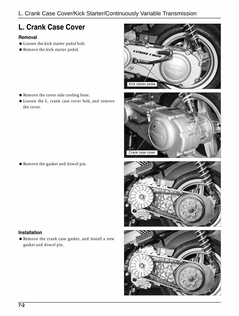
InstallationRemove the crank case gasket, and install a new
gasket and dowel pin.
L. Crank Case CoverRemovalLoosen the kick starter pedal bolt.Remove the kick starter pedal.
Remove the cover side cooling hose.Loosen the L. crank case cover bolt, and remove
the cover.
Remove the gasket and dowel pin.
7-2
Crank case cover
Kick starter pedal
L. Crank Case Cover/Kick Starter/Continuously Variable Transmission
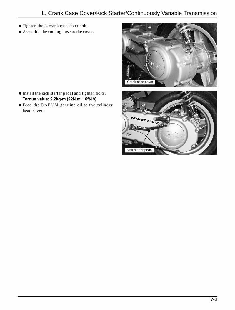
Tighten the L. crank case cover bolt.Assemble the cooling hose to the cover.
Install the kick starter pedal and tighten bolts.Torque value: 2.2kg-m (22N.m, 16ft-Ib)
Feed the DAELIM genuine oil to the cylinderhead cover.
7-3
Crank case cover
Kick starter pedal
L. Crank Case Cover/Kick Starter/Continuously Variable Transmission
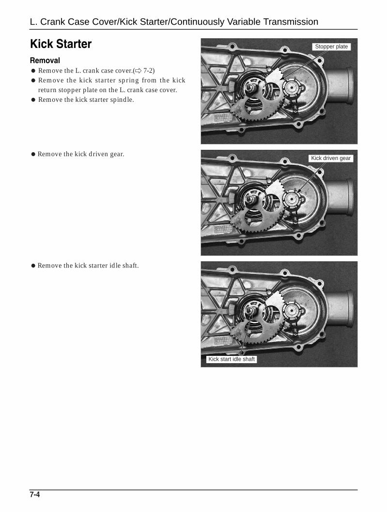
Kick StarterRemoval Remove the L. crank case cover.( 7-2) Remove the kick starter spring from the kick
return stopper plate on the L. crank case cover. Remove the kick starter spindle.
Remove the kick driven gear.
Remove the kick starter idle shaft.
7-4
Kick driven gear
Stopper plate
Kick start idle shaft
L. Crank Case Cover/Kick Starter/Continuously Variable Transmission
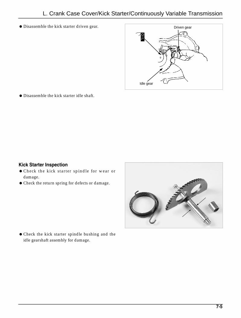
Disassemble the kick starter driven gear.
Disassemble the kick starter idle shaft.
Kick Starter InspectionCheck the kick starter spindle for wear or
damage.Check the return spring for defects or damage.
Check the kick starter spindle bushing and theidle gearshaft assembly for damage.
7-5
Driven gear
Idle gear
OIL
L. Crank Case Cover/Kick Starter/Continuously Variable Transmission
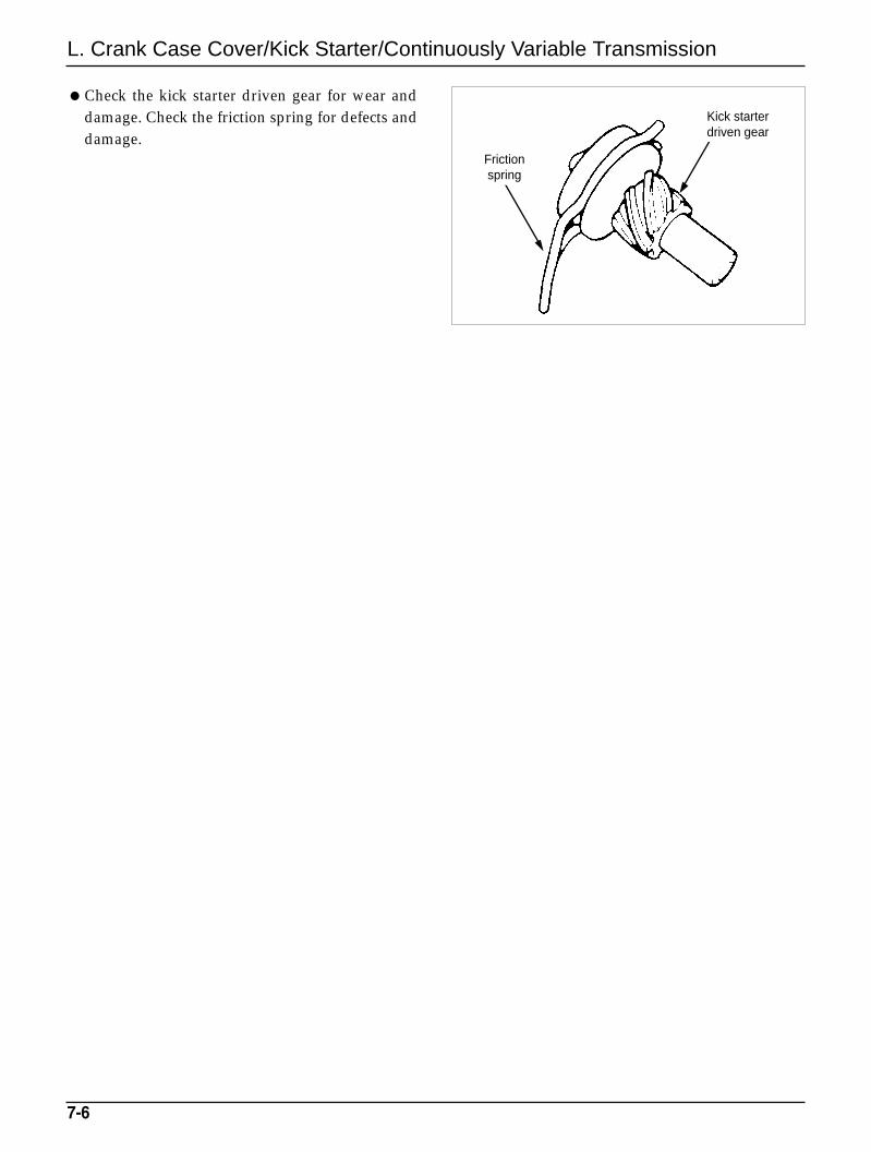
Check the kick starter driven gear for wear anddamage. Check the friction spring for defects anddamage.
7-6
Frictionspring
Kick starter driven gear
L. Crank Case Cover/Kick Starter/Continuously Variable Transmission
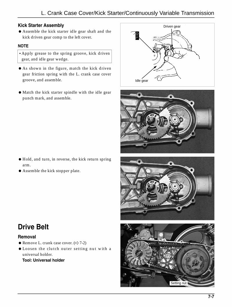
Kick Starter AssemblyAssemble the kick starter idle gear shaft and the
kick driven gear comp to the left cover.
NOTE
As shown in the figure, match the kick drivengear friction spring with the L. crank case covergroove, and assemble.
Match the kick starter spindle with the idle gearpunch mark, and assemble.
Hold, and turn, in reverse, the kick return springarm.
Assemble the kick stopper plate.
Drive BeltRemovalRemove L. crank case cover. ( 7-2)Loosen the clutch outer setting nut with a
universal holder.Tool: Universal holder
7-7
Setting nut
Driven gear
Idle gear
OIL
•Apply grease to the spring groove, kick drivengear, and idle gear wedge.
L. Crank Case Cover/Kick Starter/Continuously Variable Transmission
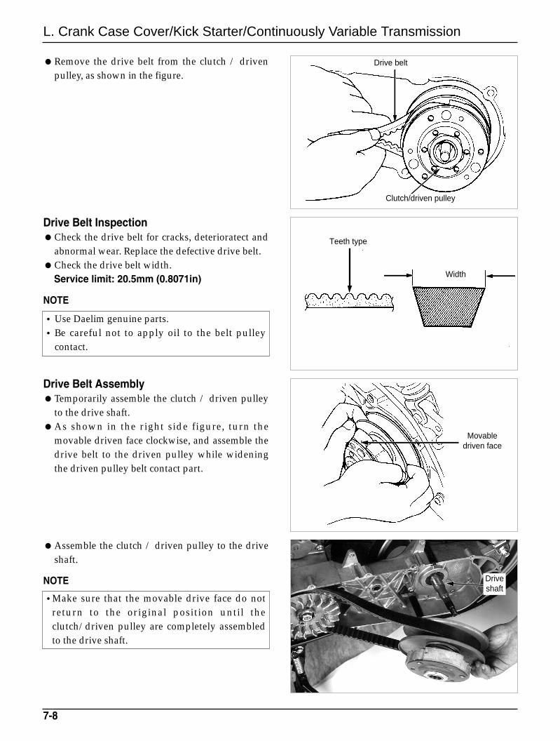
Drive Belt InspectionCheck the drive belt for cracks, deterioratect and
abnormal wear. Replace the defective drive belt.Check the drive belt width.
Service limit: 20.5mm (0.8071in)
NOTE
Remove the drive belt from the clutch / drivenpulley, as shown in the figure.
Drive Belt AssemblyTemporarily assemble the clutch / driven pulley
to the drive shaft.As shown in the right side figure, turn the
movable driven face clockwise, and assemble thedrive belt to the driven pulley while wideningthe driven pulley belt contact part.
Assemble the clutch / driven pulley to the driveshaft.
NOTE
7-8
•Make sure that the movable drive face do notreturn to the original position until theclutch/driven pulley are completely assembledto the drive shaft.
•Use Daelim genuine parts.•Be careful not to apply oil to the belt pulley
contact.
Driveshaft
Drive belt
Clutch/driven pulley
Width
Movabledriven face
Teeth type
L. Crank Case Cover/Kick Starter/Continuously Variable Transmission
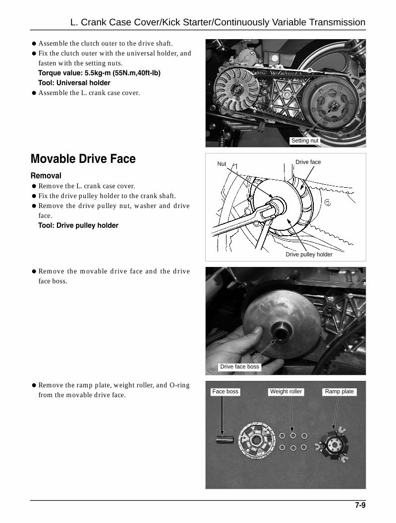
Movable Drive FaceRemovalRemove the L. crank case cover.Fix the drive pulley holder to the crank shaft.Remove the drive pulley nut, washer and drive
face.Tool: Drive pulley holder
Assemble the clutch outer to the drive shaft.Fix the clutch outer with the universal holder, and
fasten with the setting nuts.Torque value: 5.5kg-m (55N.m,40ft-Ib)Tool: Universal holder
Assemble the L. crank case cover.
Remove the movable drive face and the driveface boss.
Remove the ramp plate, weight roller, and O-ringfrom the movable drive face.
7-9
Drive face boss
Ramp plateWeight rollerFace boss
Drive faceNut
Drive pulley holder
Setting nut
L. Crank Case Cover/Kick Starter/Continuously Variable Transmission
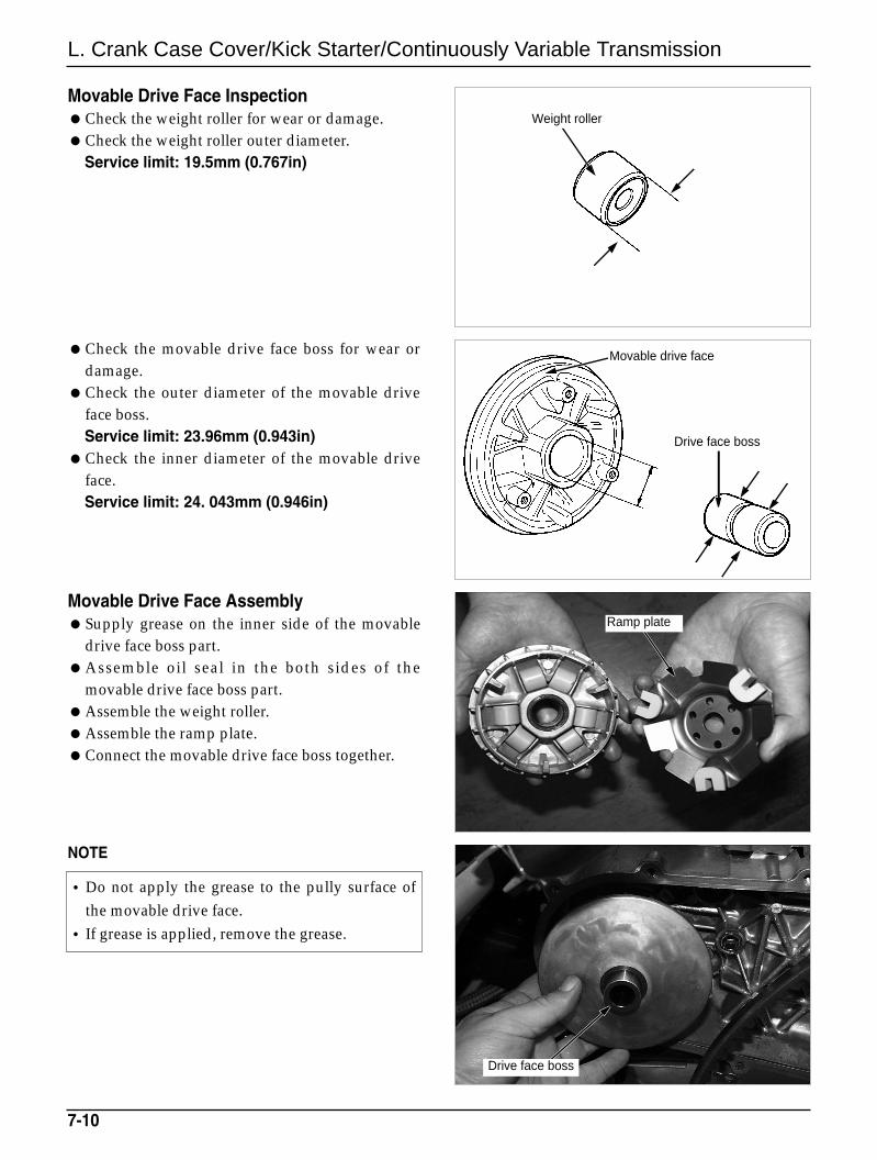
Check the movable drive face boss for wear ordamage.
Check the outer diameter of the movable driveface boss.Service limit: 23.96mm (0.943in)
Check the inner diameter of the movable driveface.Service limit: 24. 043mm (0.946in)
Movable Drive Face InspectionCheck the weight roller for wear or damage.Check the weight roller outer diameter.
Service limit: 19.5mm (0.767in)
Movable Drive Face AssemblySupply grease on the inner side of the movable
drive face boss part.Assemble oil seal in the both sides of the
movable drive face boss part.Assemble the weight roller.Assemble the ramp plate.Connect the movable drive face boss together.
NOTE
7-10
•Do not apply the grease to the pully surface ofthe movable drive face.
• If grease is applied, remove the grease.
Ramp plate
Weight roller
Movable drive face
Drive face boss
Drive face boss
L. Crank Case Cover/Kick Starter/Continuously Variable Transmission
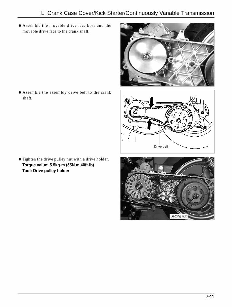
Assemble the movable drive face boss and themovable drive face to the crank shaft.
Assemble the assembly drive belt to the crankshaft.
Tighten the drive pulley nut with a drive holder. Torque value: 5.5kg-m (55N.m,40ft-Ib)Tool: Drive pulley holder
7-11
Drive belt
Setting nut
L. Crank Case Cover/Kick Starter/Continuously Variable Transmission
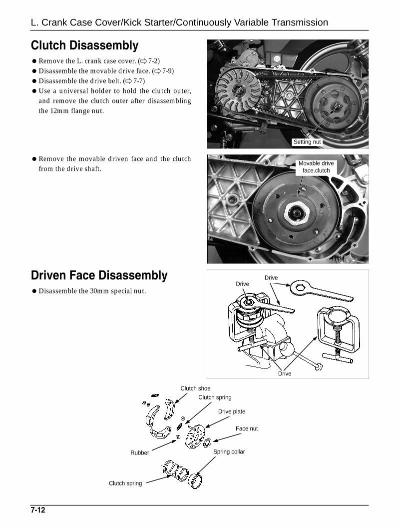
Clutch DisassemblyRemove the L. crank case cover. ( 7-2)Disassemble the movable drive face. ( 7-9)Disassemble the drive belt. ( 7-7)Use a universal holder to hold the clutch outer,
and remove the clutch outer after disassemblingthe 12mm flange nut.
Remove the movable driven face and the clutchfrom the drive shaft.
Driven Face DisassemblyDisassemble the 30mm special nut.
7-12
Movable driveface.clutch
Drive Drive
Drive
Clutch spring
Drive plate
Face nut
Rubber Spring collar
Clutch spring
Clutch shoe
Setting nut
L. Crank Case Cover/Kick Starter/Continuously Variable Transmission
7-13
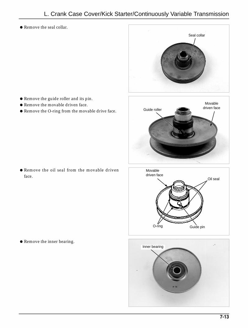
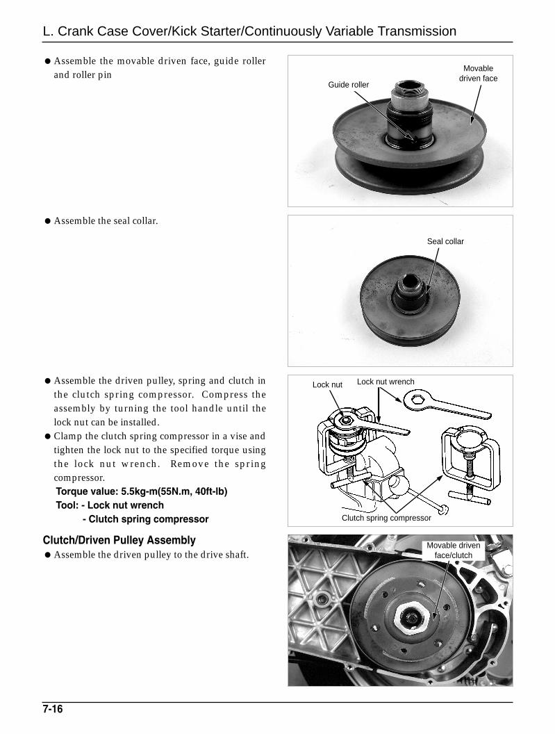
Remove the seal collar.
Remove the guide roller and its pin.Remove the movable driven face.Remove the O-ring from the movable drive face.
Remove the oil seal from the movable drivenface.
Remove the inner bearing.
Seal collar
Guide roller
Inner bearing
Movabledriven face
Oil seal
Guide pinO-ring
Movabledriven face
L. Crank Case Cover/Kick Starter/Continuously Variable Transmission
7-14
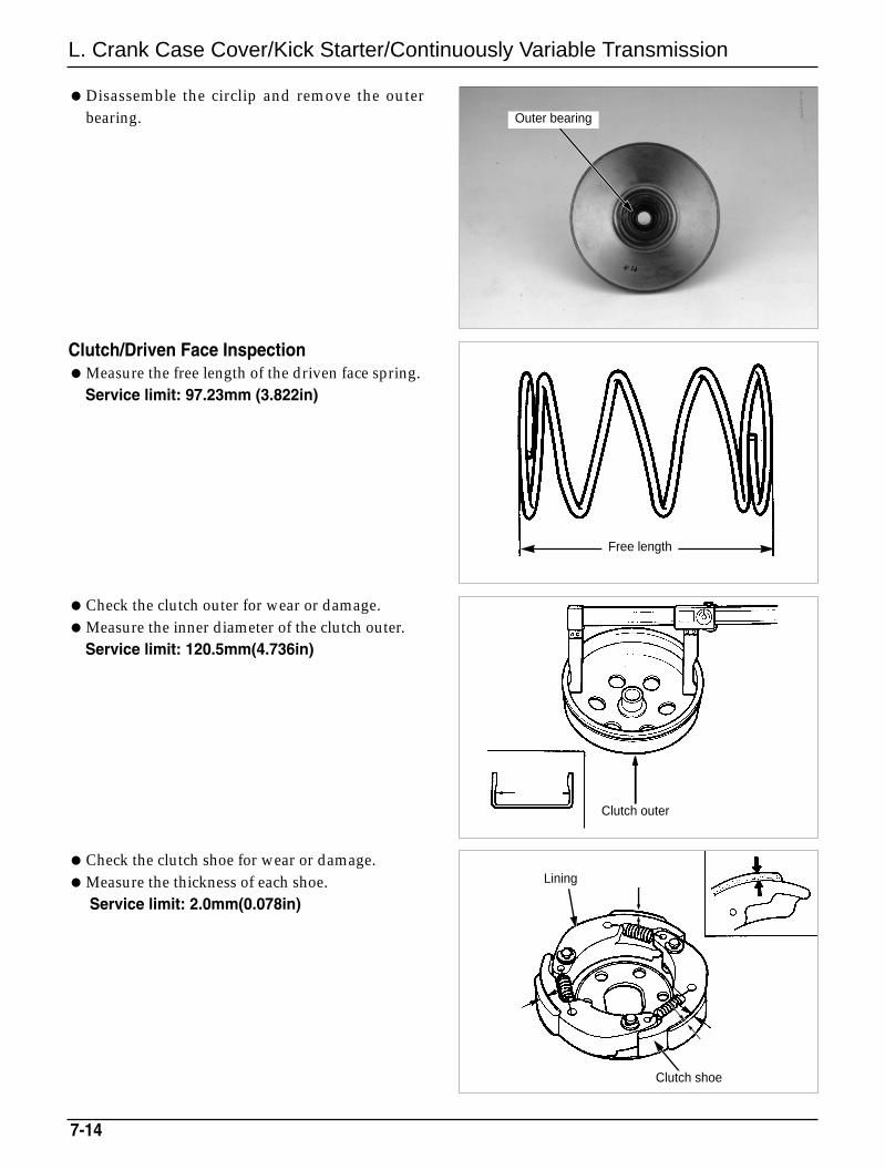
Disassemble the circlip and remove the outerbearing.
Clutch/Driven Face InspectionMeasure the free length of the driven face spring.
Service limit: 97.23mm (3.822in)
Check the clutch outer for wear or damage.Measure the inner diameter of the clutch outer.
Service limit: 120.5mm(4.736in)
Check the clutch shoe for wear or damage.Measure the thickness of each shoe.
Service limit: 2.0mm(0.078in)
Outer bearing
Lining
Free length
Clutch outer
Clutch shoe
L. Crank Case Cover/Kick Starter/Continuously Variable Transmission
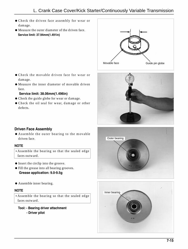
Check the driven face assembly for wear ordamage.
Measure the outer diameter of the driven face.Service limit: 37.94mm(1.491in)
Check the movable driven face for wear ordamage.
Measure the inner diameter of movable drivenface.Service limit: 38.06mm(1.496in)
Check the guide globe for wear or damage.Check the oil seal for wear, damage or other
defects.
Driven Face AssemblyAssemble the outer bearing to the movable
driven face.
NOTE
Insert the circlip into the groove.Fill the grease into all bearing grooves.
Grease application: 9.0-9.5g
7-15
•Assemble the bearing so that the sealed edgefaces outward.
Assemble inner bearing.
NOTE
Tool: - Bearing driver attachment - Driver pilot
•Assemble the bearing so that the sealed edgefaces outward.
Outer bearing
Inner bearing
Movable face Guide pin globe
L. Crank Case Cover/Kick Starter/Continuously Variable Transmission
Assemble the seal collar.
Assemble the movable driven face, guide rollerand roller pin
Assemble the driven pulley, spring and clutch inthe clutch spring compressor. Compress theassembly by turning the tool handle until thelock nut can be installed.
Clamp the clutch spring compressor in a vise andtighten the lock nut to the specified torque usingthe lock nut wrench. Remove the springcompressor.Torque value: 5.5kg-m(55N.m, 40ft-lb)Tool: - Lock nut wrench
- Clutch spring compressor
Clutch/Driven Pulley AssemblyAssemble the driven pulley to the drive shaft.
7-16
Seal collar
Movable drivenface/clutch
Clutch spring compressor
Lock nut wrenchLock nut
Guide roller
Movabledriven face
L. Crank Case Cover/Kick Starter/Continuously Variable Transmission
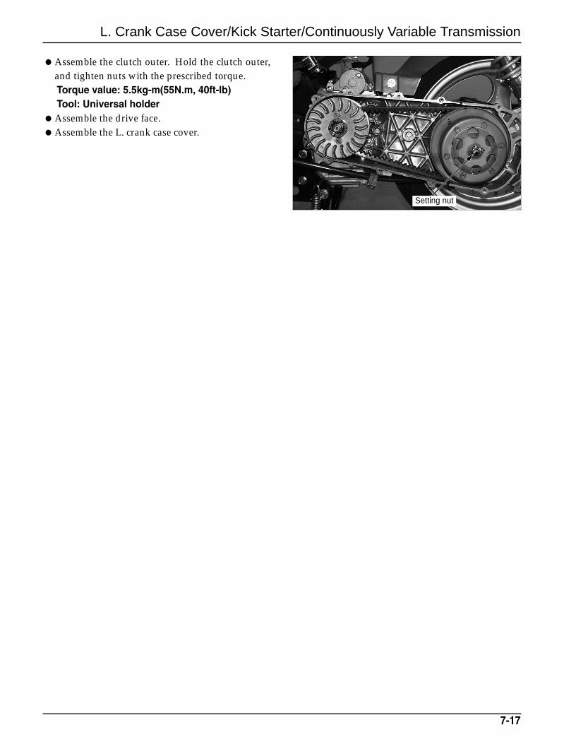
Assemble the clutch outer. Hold the clutch outer,and tighten nuts with the prescribed torque.Torque value: 5.5kg-m(55N.m, 40ft-lb)Tool: Universal holder
Assemble the drive face.Assemble the L. crank case cover.
7-17
Setting nut
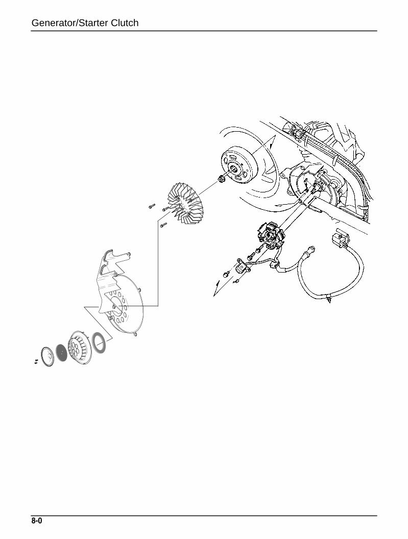
Generator/Starter Clutch
8-0
8-1
8. Generator/Starter Clutch
Service Information 8-1Shroud 8-2A.C Generator 8-2
R.Crank Case Cover 8-4Starter Clutch 8-6
Service InformationGeneral SafetyThis section describes the removal and assembling of the A.C. generator.For information on A.C generator inspection, refer to the section 15.The charging system can be maintained without removing the engine.
Specifications
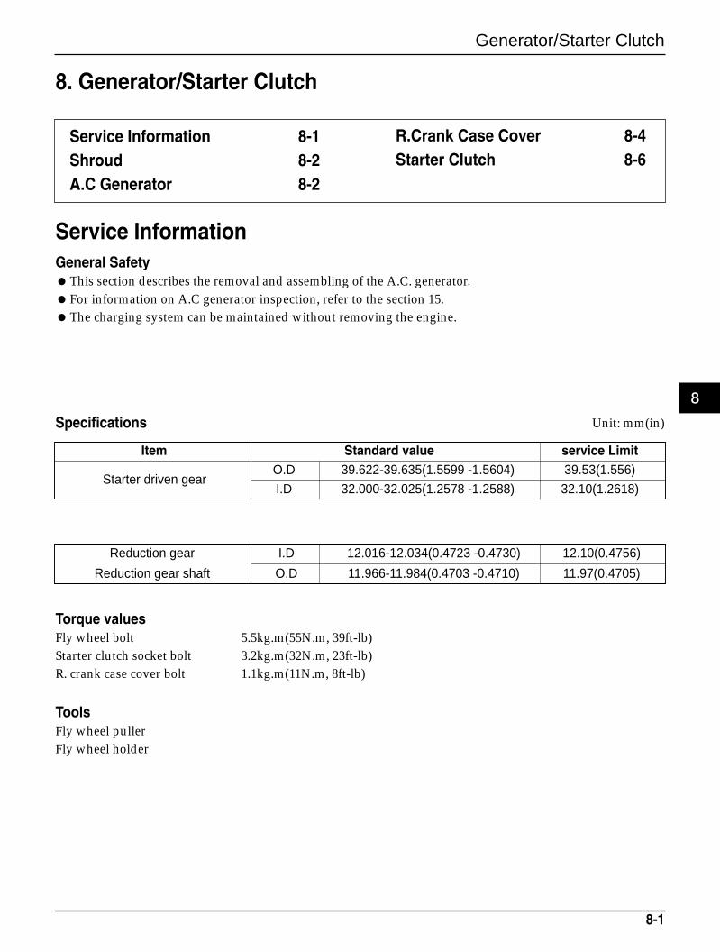
Item Standard value service Limit
Starter driven gearO.D 39.622-39.635(1.5599 -1.5604) 39.53(1.556)
I.D 32.000-32.025(1.2578 -1.2588) 32.10(1.2618)
Reduction gear I.D 12.016-12.034(0.4723 -0.4730) 12.10(0.4756)
Reduction gear shaft O.D 11.966-11.984(0.4703 -0.4710) 11.97(0.4705)
Torque valuesFly wheel bolt 5.5kg.m(55N.m, 39ft-lb)Starter clutch socket bolt 3.2kg.m(32N.m, 23ft-lb)R. crank case cover bolt 1.1kg.m(11N.m, 8ft-lb)
ToolsFly wheel pullerFly wheel holder
Unit: mm(in)
8
Generator/Starter Clutch
Generator/Starter Clutch
8-2
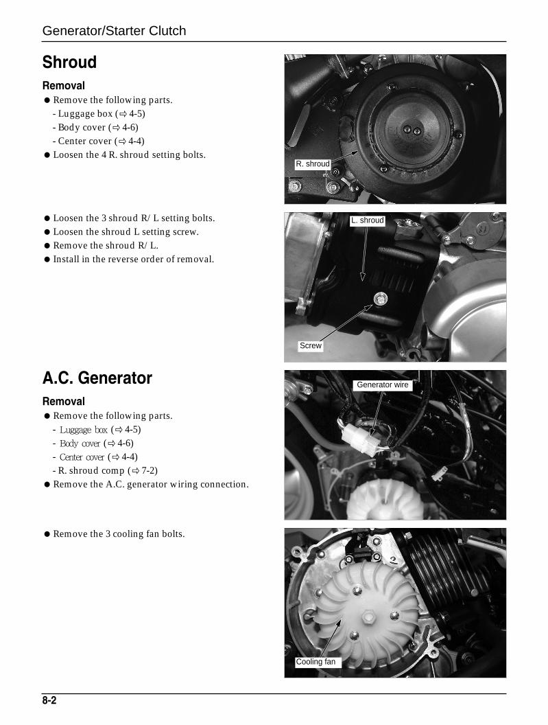
ShroudRemovalRemove the following parts.
- Luggage box (4-5)- Body cover ( 4-6)- Center cover (4-4)
Loosen the 4 R. shroud setting bolts.
Loosen the 3 shroud R/L setting bolts.Loosen the shroud L setting screw.Remove the shroud R/L. Install in the reverse order of removal.
A.C. GeneratorRemovalRemove the following parts.
- Luggage box ( 4-5)- Body cover ( 4-6)- Center cover ( 4-4)- R. shroud comp ( 7-2)
Remove the A.C. generator wiring connection.
Remove the 3 cooling fan bolts.
Screw
L. shroud
Generator wire
Cooling fan
R. shroud
Generator/Starter Clutch
8-3
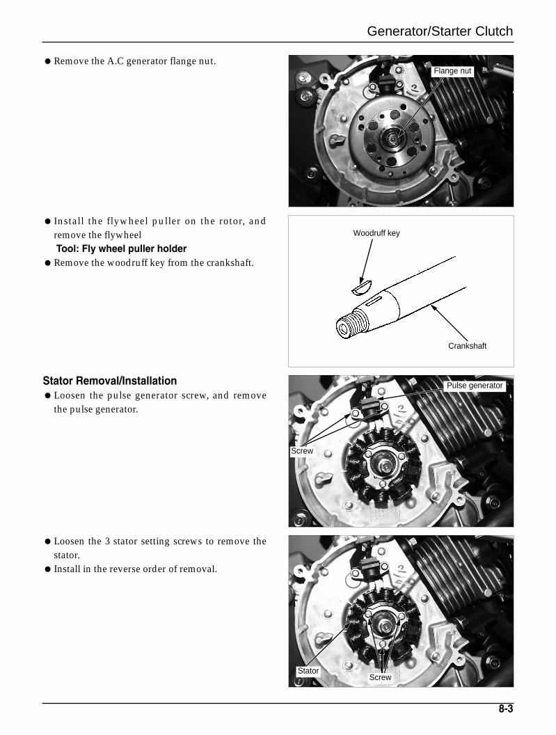
Remove the A.C generator flange nut.
Install the flywheel puller on the rotor, andremove the flywheelTool: Fly wheel puller holder
Remove the woodruff key from the crankshaft.
Stator Removal/InstallationLoosen the pulse generator screw, and remove
the pulse generator.
Loosen the 3 stator setting screws to remove thestator.
Install in the reverse order of removal.
Flange nut
Pulse generator
Crankshaft
Woodruff key
Screw
ScrewStator
Generator/Starter Clutch
8-4
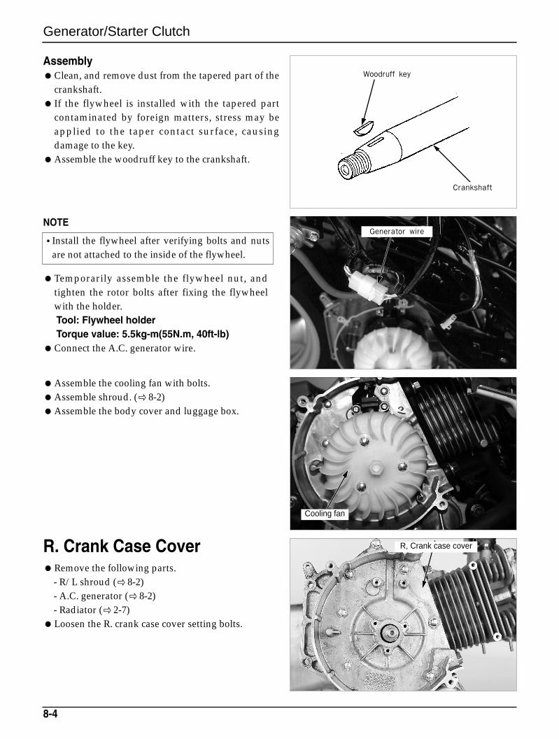
AssemblyClean, and remove dust from the tapered part of the
crankshaft. If the flywheel is installed with the tapered part
contaminated by foreign matters, stress may beapplied to the taper contact surface, causingdamage to the key.
Assemble the woodruff key to the crankshaft.
NOTE
Temporarily assemble the flywheel nut, andtighten the rotor bolts after fixing the flywheelwith the holder.Tool: Flywheel holderTorque value: 5.5kg-m(55N.m, 40ft-lb)
Connect the A.C. generator wire.
Assemble the cooling fan with bolts.Assemble shroud. (8-2)Assemble the body cover and luggage box.
R. Crank Case CoverRemove the following parts.
- R/L shroud (8-2)- A.C. generator ( 8-2)- Radiator ( 2-7)
Loosen the R. crank case cover setting bolts.
•Install the flywheel after verifying bolts and nutsare not attached to the inside of the flywheel.
Crankshaft
Woodruff key
R, Crank case cover
Generator wire
Cooling fan
Generator/Starter Clutch
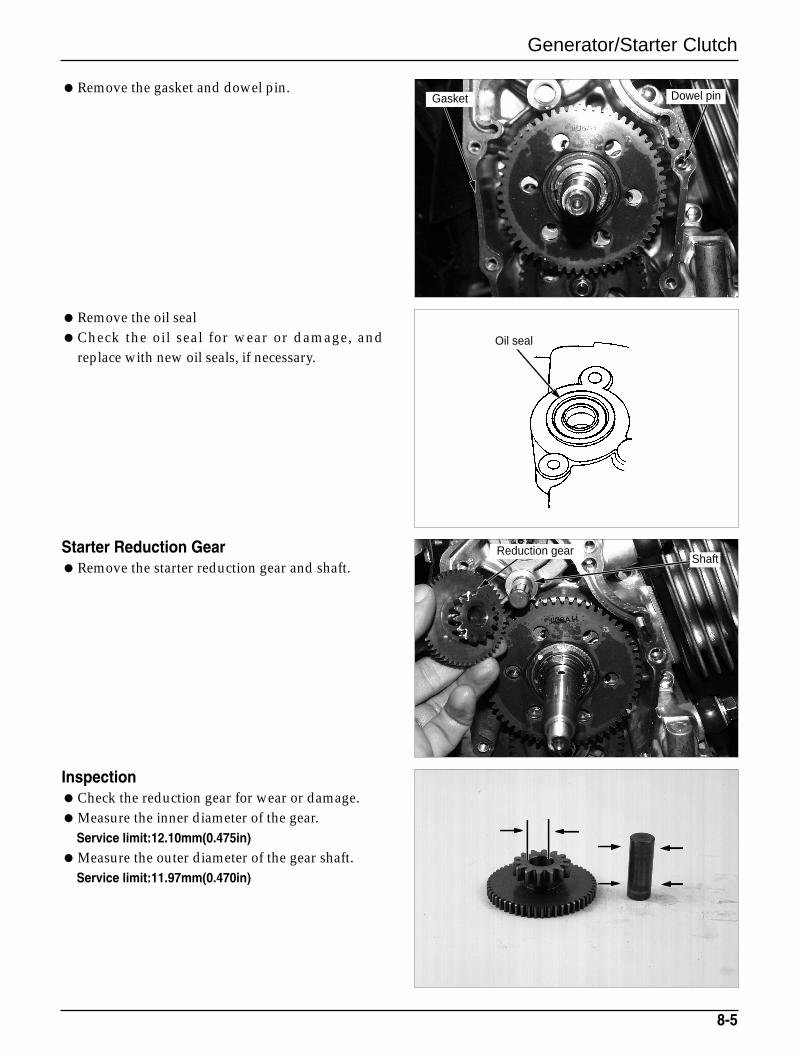
Remove the gasket and dowel pin.
Remove the oil sealCheck the oil seal for wear or damage, and
replace with new oil seals, if necessary.
Starter Reduction GearRemove the starter reduction gear and shaft.
InspectionCheck the reduction gear for wear or damage.Measure the inner diameter of the gear.
Service limit:12.10mm(0.475in)
Measure the outer diameter of the gear shaft.Service limit:11.97mm(0.470in)
8-5
Gasket
Oil seal
Dowel pin
Reduction gearShaft
Generator/Starter Clutch
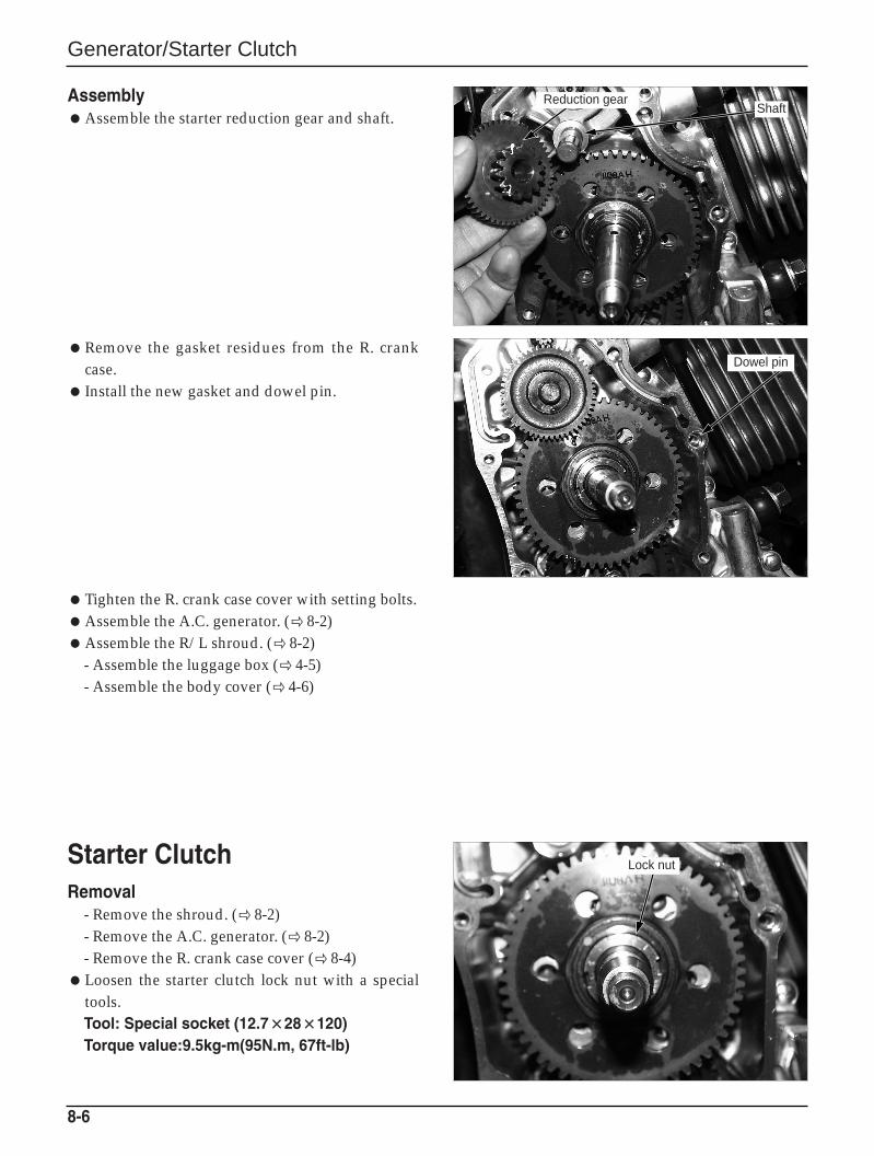
AssemblyAssemble the starter reduction gear and shaft.
Remove the gasket residues from the R. crankcase.
Install the new gasket and dowel pin.
Tighten the R. crank case cover with setting bolts.Assemble the A.C. generator. (8-2)Assemble the R/L shroud. (8-2)
- Assemble the luggage box ( 4-5)- Assemble the body cover ( 4-6)
Starter Clutch Removal
- Remove the shroud. ( 8-2)- Remove the A.C. generator. ( 8-2)- Remove the R. crank case cover ( 8-4)
Loosen the starter clutch lock nut with a specialtools.Tool: Special socket (12.7××28××120)Torque value:9.5kg-m(95N.m, 67ft-lb)
8-6
Dowel pin
Lock nut
Reduction gearShaft
Driven gear
Lock nut
Needle bearing
Starter oneway clutch ass’y
Starter clutch
Generator/Starter Clutch
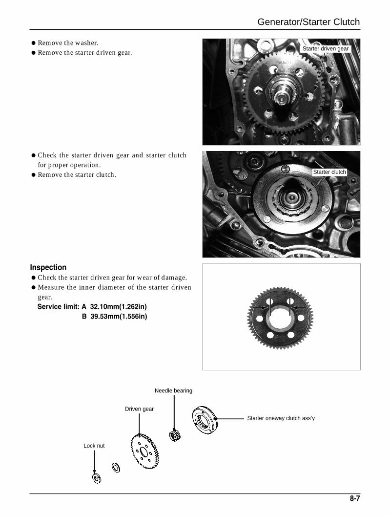
Remove the washer.Remove the starter driven gear.
Check the starter driven gear and starter clutchfor proper operation.
Remove the starter clutch.
InspectionCheck the starter driven gear for wear of damage.Measure the inner diameter of the starter driven
gear.Service limit: A 32.10mm(1.262in)
B 39.53mm(1.556in)
8-7
Starter driven gear
Generator/Starter Clutch
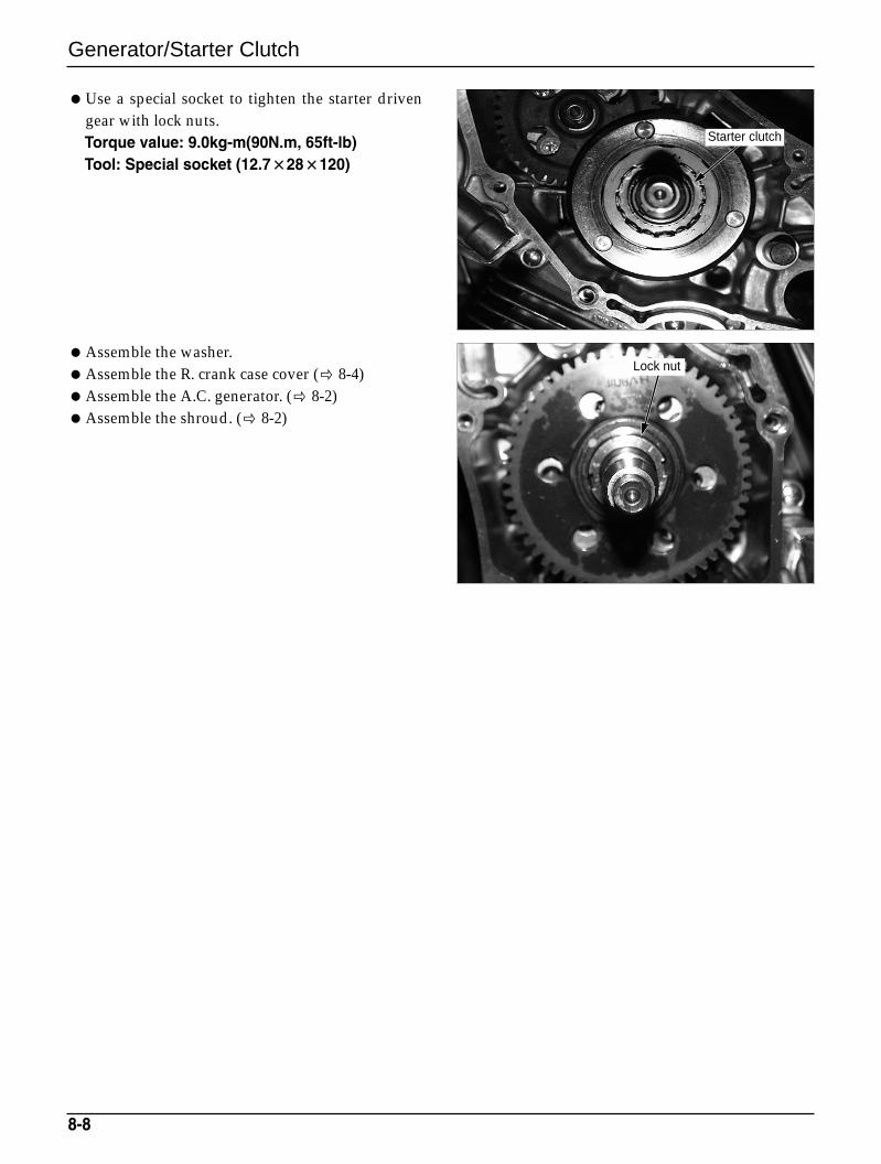
Use a special socket to tighten the starter drivengear with lock nuts.Torque value: 9.0kg-m(90N.m, 65ft-lb)Tool: Special socket (12.7××28××120)
Assemble the washer.Assemble the R. crank case cover ( 8-4)Assemble the A.C. generator. ( 8-2)Assemble the shroud. ( 8-2)
8-8
Starter clutch
Lock nut
Cylinder Head/Valve
Service InformationGeneral SafetyThe rocker arm and the camshaft can be serviced without removing the engine. However, the engine must
be removed from the frame to maintain the cylinder head.The oil of camshaft oil is supplied through the cylinder head oil hole. Clean the oil hole prior to
assembling the cylinder head.
Specifications
9-1
9. Cylinder Head/Valve
Services information 9-1
Troubleshooting 9-2
Camshaft Removal 9-3
Cylinder Head Removal 9-5
Cylinder Head Disassembly 9-5
Valve guide replacement 9-7
Valve seat Inspection/Adjustment 9-8
Cylinder head Assembly 9-11
Cylinder Head Installation 9-12
Camshaft Assembly 9-13
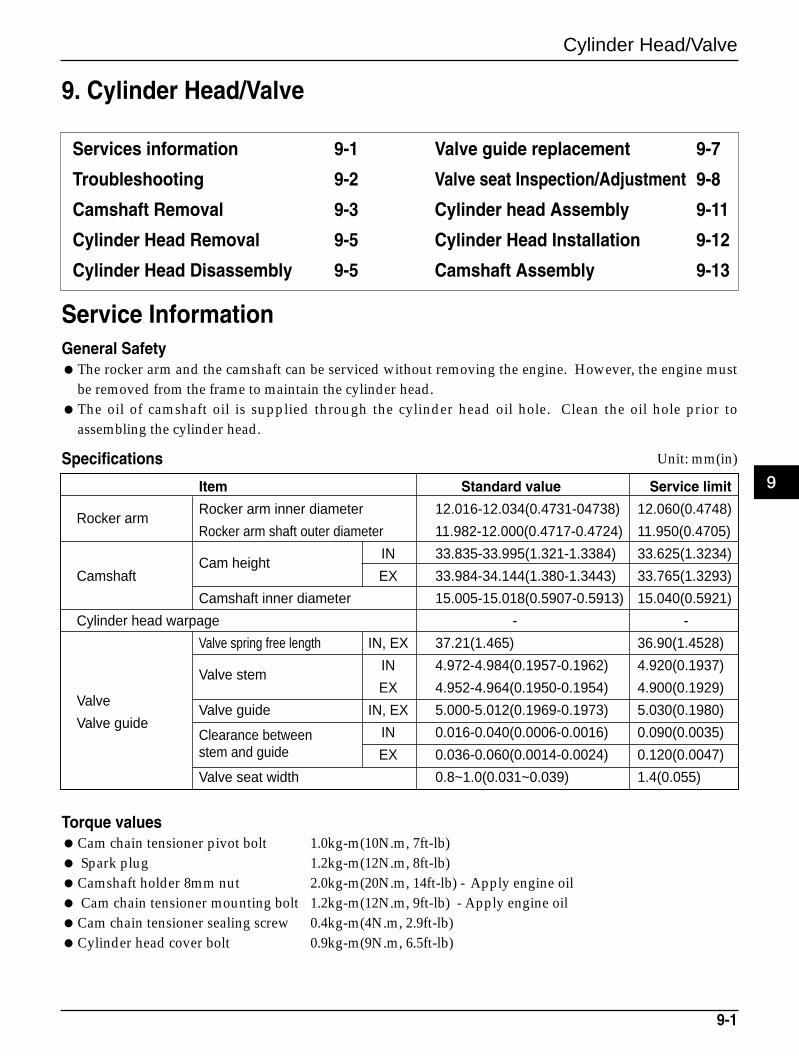
Item Standard value Service limit
Rocker armRocker arm inner diameter 12.016-12.034(0.4731-04738) 12.060(0.4748)
Rocker arm shaft outer diameter 11.982-12.000(0.4717-0.4724) 11.950(0.4705)
Cam heightIN 33.835-33.995(1.321-1.3384) 33.625(1.3234)
Camshaft EX 33.984-34.144(1.380-1.3443) 33.765(1.3293)
Camshaft inner diameter 15.005-15.018(0.5907-0.5913) 15.040(0.5921)
Cylinder head warpage - -
Valve spring free length IN, EX 37.21(1.465) 36.90(1.4528)
Valve stemIN 4.972-4.984(0.1957-0.1962) 4.920(0.1937)
EX 4.952-4.964(0.1950-0.1954) 4.900(0.1929)Valve
Valve guide IN, EX 5.000-5.012(0.1969-0.1973) 5.030(0.1980)Valve guide
Clearance between IN 0.016-0.040(0.0006-0.0016) 0.090(0.0035)stem and guide EX 0.036-0.060(0.0014-0.0024) 0.120(0.0047)
Valve seat width 0.8~1.0(0.031~0.039) 1.4(0.055)
Unit: mm(in)
Torque valuesCam chain tensioner pivot bolt 1.0kg-m(10N.m, 7ft-lb) Spark plug 1.2kg-m(12N.m, 8ft-lb) Camshaft holder 8mm nut 2.0kg-m(20N.m, 14ft-lb) - Apply engine oil Cam chain tensioner mounting bolt 1.2kg-m(12N.m, 9ft-lb) - Apply engine oilCam chain tensioner sealing screw 0.4kg-m(4N.m, 2.9ft-lb)Cylinder head cover bolt 0.9kg-m(9N.m, 6.5ft-lb)
9
Cylinder Head/Valve
ToolsValve guide reamerValve guide driverValve spring compressorValve seat cutterSeat Cutter IN 37(21.5mm)
EX 37(18.5mm)IN 45(22mm)EX 45(22mm)IN 55(20mm)EX 55(20mm)
TroubleshootingCylinder head operation problem can be diagnosed,
in general, by a compression test, or by checkingnoises on the top of the engine.
Low compression or uneven compressionValves
- Faulty hydraulic tappet- Burned or bent valves- Incorrect valve timing- Broken valve spring
Cylinder head- Leaking or damaged head gasket- Warped or cracked cylinder head
Cylinder and piston (Refer to Section 10)
Compression too high- Excessive carbon build-up on piston head or
combustion chamber
Excessive noiseFaulty hydraulic valve tappet system
- Low engine oil level- Contaminated oil- Low oil pressure- Damaged hydraulic tappet
Sticking valve or broken valve spring
Damaged or worn camshaft
Loose or worn cam chain
Worn or damaged cam chain tensioner
Worn cam sprocket teeth
9-2
“T” mark
Cylinder Head/Valve
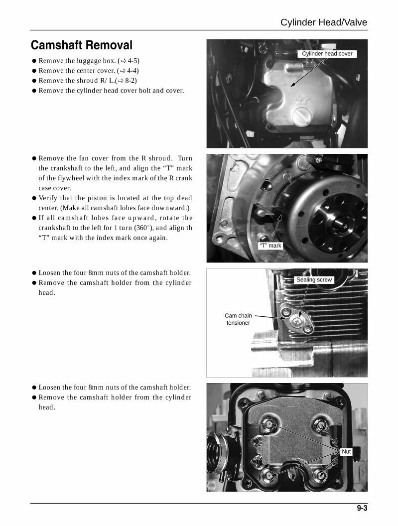
Camshaft RemovalRemove the luggage box. ( 4-5)Remove the center cover. ( 4-4)Remove the shroud R/L.( 8-2)Remove the cylinder head cover bolt and cover.
Remove the fan cover from the R shroud. Turnthe crankshaft to the left, and align the “T” markof the flywheel with the index mark of the R crankcase cover.
Verify that the piston is located at the top deadcenter. (Make all camshaft lobes face downward.)
If all camshaft lobes face upward, rotate thecrankshaft to the left for 1 turn (360), and align th“T” mark with the index mark once again.
Loosen the four 8mm nuts of the camshaft holder.Remove the camshaft holder from the cylinder
head.
Loosen the four 8mm nuts of the camshaft holder.Remove the camshaft holder from the cylinder
head.
9-3
Cylinder head cover
Sealing screw
Cam chaintensioner
Nut
Cylinder Head/Valve
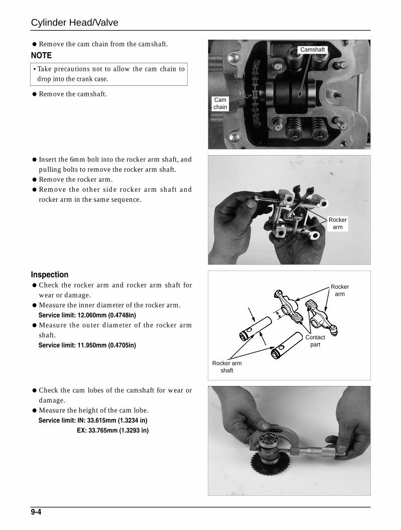
Remove the cam chain from the camshaft.
NOTE
Remove the camshaft.
Insert the 6mm bolt into the rocker arm shaft, andpulling bolts to remove the rocker arm shaft.
Remove the rocker arm.Remove the other side rocker arm shaft and
rocker arm in the same sequence.
InspectionCheck the rocker arm and rocker arm shaft for
wear or damage.Measure the inner diameter of the rocker arm.
Service limit: 12.060mm (0.4748in)
Measure the outer diameter of the rocker armshaft.Service limit: 11.950mm (0.4705in)
Check the cam lobes of the camshaft for wear ordamage.
Measure the height of the cam lobe.Service limit: IN: 33.615mm (1.3234 in)
EX: 33.765mm (1.3293 in)
9-4
Rockerarm
Rockerarm
Contactpart
Rocker armshaft
Camshaft
Camchain
•Take precautions not to allow the cam chain todrop into the crank case.
Cylinder Head/Valve
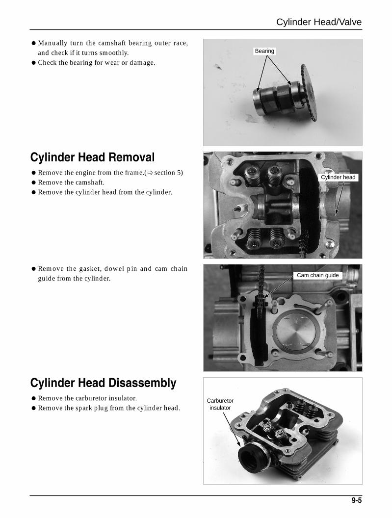
Manually turn the camshaft bearing outer race,and check if it turns smoothly.
Check the bearing for wear or damage.
Cylinder Head RemovalRemove the engine from the frame.( section 5)Remove the camshaft.Remove the cylinder head from the cylinder.
Remove the gasket, dowel pin and cam chainguide from the cylinder.
Cylinder Head DisassemblyRemove the carburetor insulator.Remove the spark plug from the cylinder head.
9-5
Bearing
Cylinder head
Cam chain guide
Carburetorinsulator
Cylinder Head/Valve
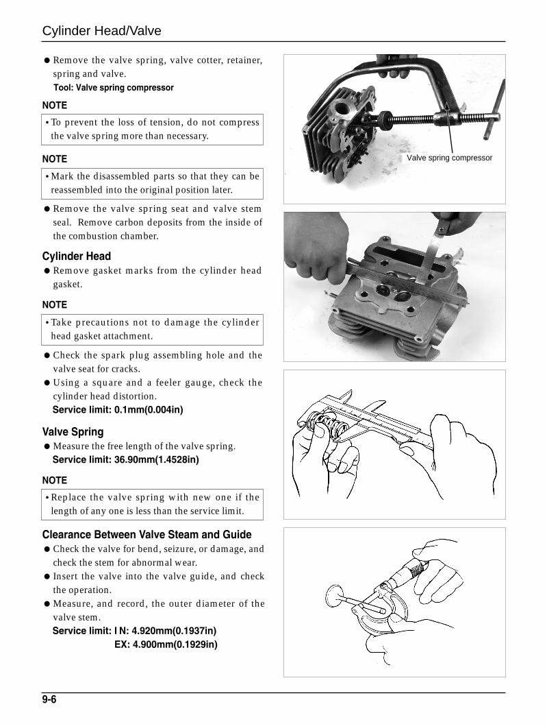
Remove the valve spring, valve cotter, retainer,spring and valve.Tool: Valve spring compressor
NOTE
NOTE
Remove the valve spring seat and valve stemseal. Remove carbon deposits from the inside ofthe combustion chamber.
Cylinder HeadRemove gasket marks from the cylinder head
gasket.
NOTE
Check the spark plug assembling hole and thevalve seat for cracks.
Using a square and a feeler gauge, check thecylinder head distortion.Service limit: 0.1mm(0.004in)
Valve SpringMeasure the free length of the valve spring.
Service limit: 36.90mm(1.4528in)
NOTE
Clearance Between Valve Steam and GuideCheck the valve for bend, seizure, or damage, and
check the stem for abnormal wear. Insert the valve into the valve guide, and check
the operation.Measure, and record, the outer diameter of the
valve stem.Service limit: I N: 4.920mm(0.1937in)
EX: 4.900mm(0.1929in)
9-6
•To prevent the loss of tension, do not compressthe valve spring more than necessary.
•Mark the disassembled parts so that they can bereassembled into the original position later.
•Take precautions not to damage the cylinderhead gasket attachment.
•Replace the valve spring with new one if thelength of any one is less than the service limit.
Valve spring compressor
Cylinder Head/Valve
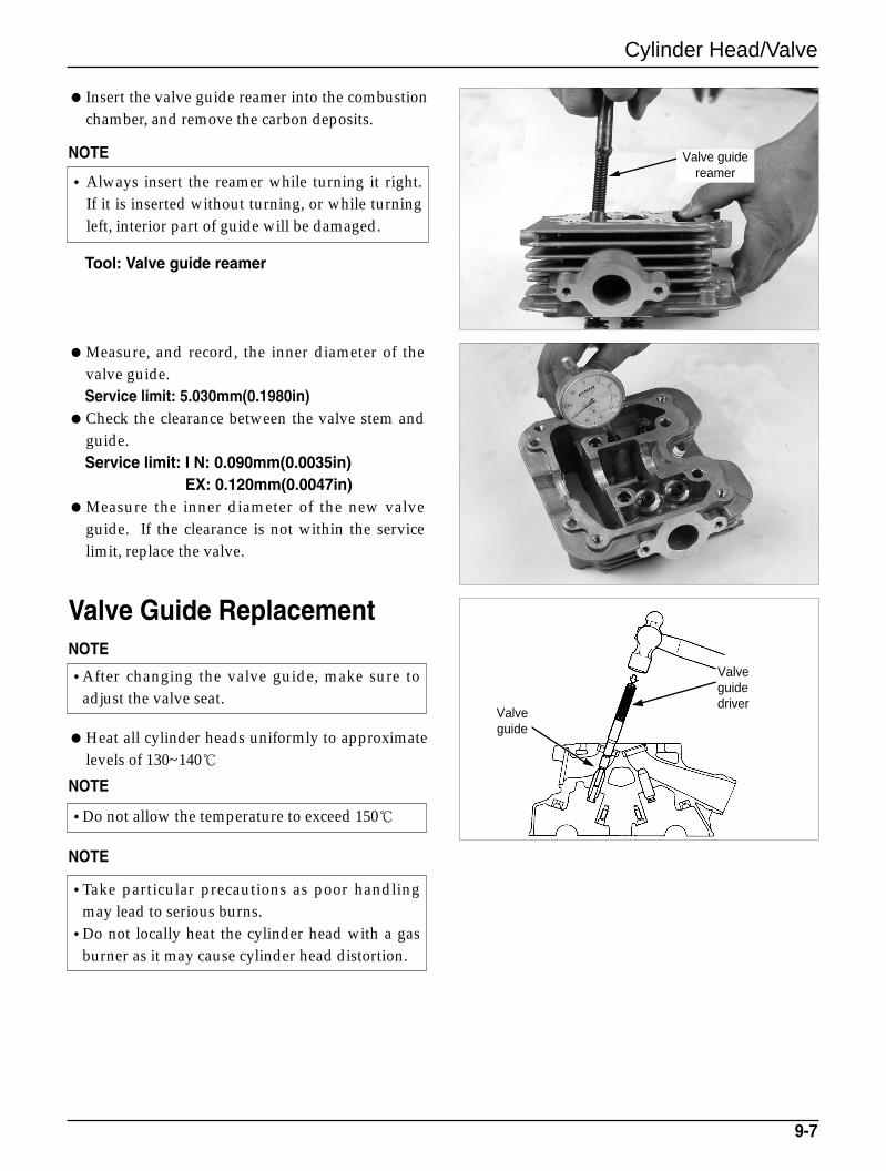
Insert the valve guide reamer into the combustionchamber, and remove the carbon deposits.
NOTE
Tool: Valve guide reamer
Measure, and record, the inner diameter of thevalve guide.Service limit: 5.030mm(0.1980in)
Check the clearance between the valve stem andguide.Service limit: I N: 0.090mm(0.0035in)
EX: 0.120mm(0.0047in)Measure the inner diameter of the new valve
guide. If the clearance is not within the servicelimit, replace the valve.
Valve Guide ReplacementNOTE
Heat all cylinder heads uniformly to approximatelevels of 130~140
NOTE
NOTE
9-7
•After changing the valve guide, make sure toadjust the valve seat.
•Do not allow the temperature to exceed 150
•Take particular precautions as poor handlingmay lead to serious burns.
•Do not locally heat the cylinder head with a gasburner as it may cause cylinder head distortion.
•Always insert the reamer while turning it right.If it is inserted without turning, or while turningleft, interior part of guide will be damaged.
Valve guidereamer
Valveguidedriver
Valveguide
Cylinder Head/Valve
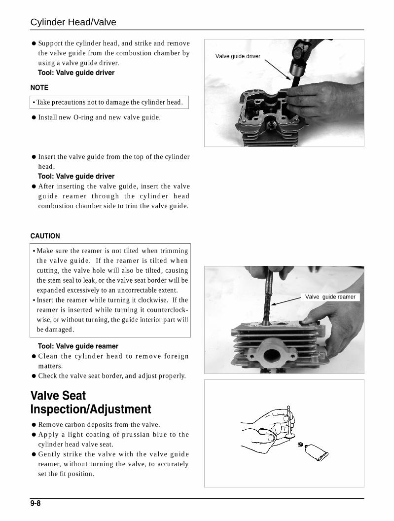
Support the cylinder head, and strike and removethe valve guide from the combustion chamber byusing a valve guide driver.Tool: Valve guide driver
NOTE
Install new O-ring and new valve guide.
Insert the valve guide from the top of the cylinderhead.Tool: Valve guide driver
After inserting the valve guide, insert the valveguide reamer through the cylinder headcombustion chamber side to trim the valve guide.
CAUTION
Tool: Valve guide reamerClean the cylinder head to remove foreign
matters.Check the valve seat border, and adjust properly.
Valve SeatInspection/AdjustmentRemove carbon deposits from the valve.Apply a light coating of prussian blue to the
cylinder head valve seat.Gently strike the valve with the valve guide
reamer, without turning the valve, to accuratelyset the fit position.
9-8
•Take precautions not to damage the cylinder head.
•Make sure the reamer is not tilted when trimmingthe valve guide. If the reamer is tilted whencutting, the valve hole will also be tilted, causingthe stem seal to leak, or the valve seat border will beexpanded excessively to an uncorrectable extent.
•Insert the reamer while turning it clockwise. If thereamer is inserted while turning it counterclock-wise, or without turning, the guide interior part willbe damaged.
Valve guide reamer
Valve guide driver
Cylinder Head/Valve
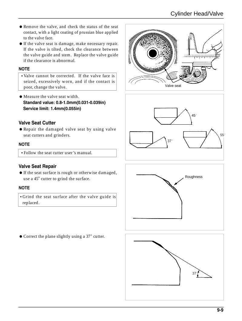
Remove the valve, and check the status of the seatcontact, with a light coating of prussian blue appliedto the valve face.
If the valve seat is damage, make necessary repair.If the valve is tilted, check the clearance betweenthe valve guide and stem. Replace the valve guideif the clearance is abnormal.
NOTE
Measure the valve seat width.Standard value: 0.8-1.0mm(0.031-0.039in)Service limit: 1.4mm(0.055in)
Valve Seat CutterRepair the damaged valve seat by using valve
seat cutters and grinders.
NOTE
Valve Seat Repair If the seat surface is rough or otherwise damaged,
use a 45°cutter to grind the surface.
NOTE
Correct the plane slightly using a 37 cutter.
9-9
•Valve cannot be corrected. If the valve face isseized, excessively worn, and if the contact ispoor, change the valve.
•Follow the seat cutter user’s manual.
•Grind the seat surface after the valve guide isreplaced.
Valve seat
Roughness
45
37
37
55
Cylinder Head/Valve
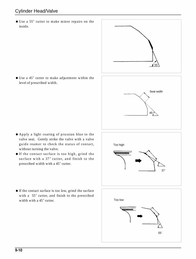
Use a 55 cutter to make minor repairs on theinside.
Use a 45 cutter to make adjustment within thelevel of prescribed width.
Apply a light coating of prussian blue to thevalve seat. Gently strike the valve with a valveguide reamer to check the status of contact,without turning the valve.
If the contact surface is too high, grind thesurface with a 37 cutter, and finish to theprescribed width with a 45 cutter.
If the contact surface is too low, grind the surfacewith a 55 cutter, and finish to the prescribedwidth with a 45 cutter.
9-10
55
45
37
55
Seat width
Too high
Too low
Cylinder Head/Valve
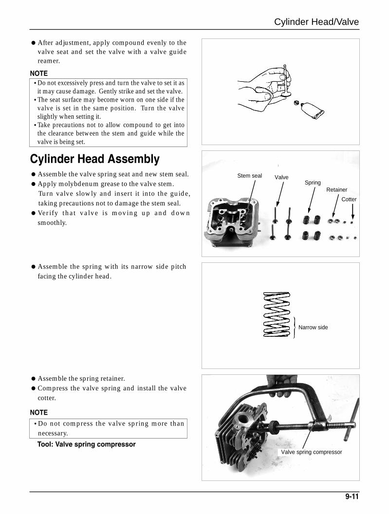
After adjustment, apply compound evenly to thevalve seat and set the valve with a valve guidereamer.
NOTE
Cylinder Head AssemblyAssemble the valve spring seat and new stem seal.Apply molybdenum grease to the valve stem.
Turn valve slowly and insert it into the guide,taking precautions not to damage the stem seal.
Verify that valve is moving up and downsmoothly.
Assemble the spring with its narrow side pitchfacing the cylinder head.
Assemble the spring retainer.Compress the valve spring and install the valve
cotter.
NOTE
Tool: Valve spring compressor
9-11
•Do not excessively press and turn the valve to set it asit may cause damage. Gently strike and set the valve.
•The seat surface may become worn on one side if thevalve is set in the same position. Turn the valveslightly when setting it.
•Take precautions not to allow compound to get intothe clearance between the stem and guide while thevalve is being set.
•Do not compress the valve spring more thannecessary.
ValveSpring
Cotter
Retainer
Stem seal
Valve spring compressor
Narrow side
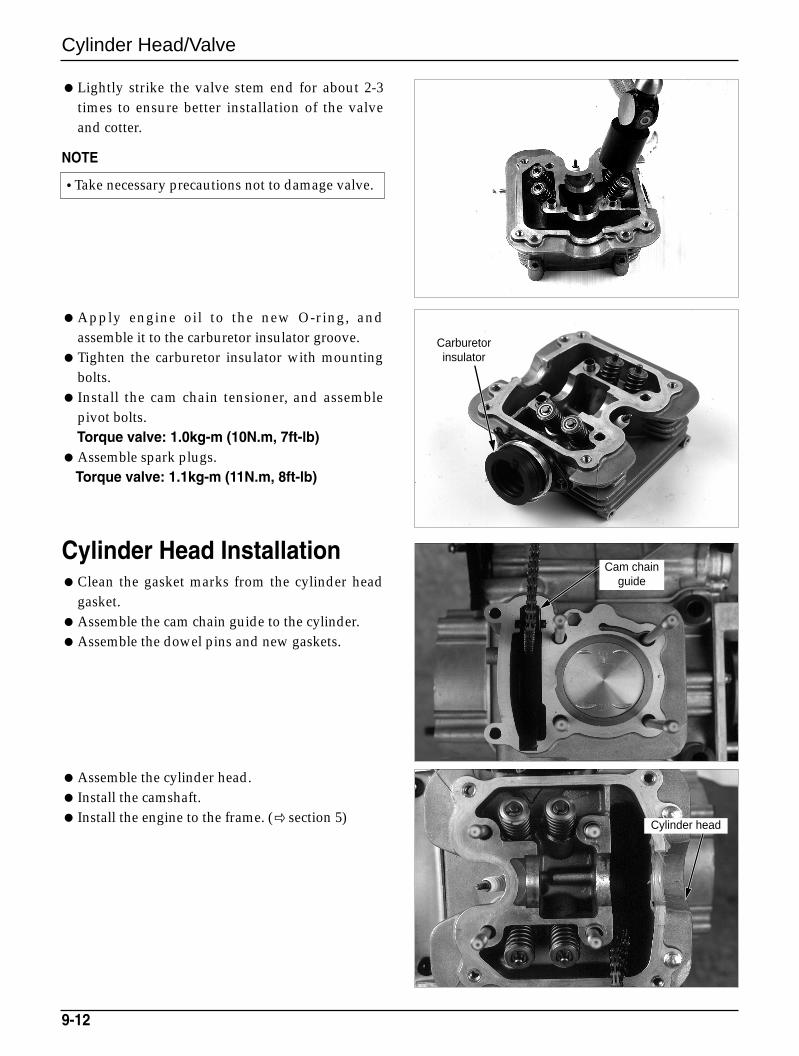
Cylinder Head/Valve
Lightly strike the valve stem end for about 2-3times to ensure better installation of the valveand cotter.
NOTE
Apply engine oil to the new O-ring, andassemble it to the carburetor insulator groove.
Tighten the carburetor insulator with mountingbolts.
Install the cam chain tensioner, and assemblepivot bolts.Torque valve: 1.0kg-m (10N.m, 7ft-lb)
Assemble spark plugs.Torque valve: 1.1kg-m (11N.m, 8ft-lb)
Cylinder Head InstallationClean the gasket marks from the cylinder head
gasket.Assemble the cam chain guide to the cylinder.Assemble the dowel pins and new gaskets.
Assemble the cylinder head. Install the camshaft. Install the engine to the frame. ( section 5)
9-12
•Take necessary precautions not to damage valve.
Carburetorinsulator
Cylinder head
Cam chainguide
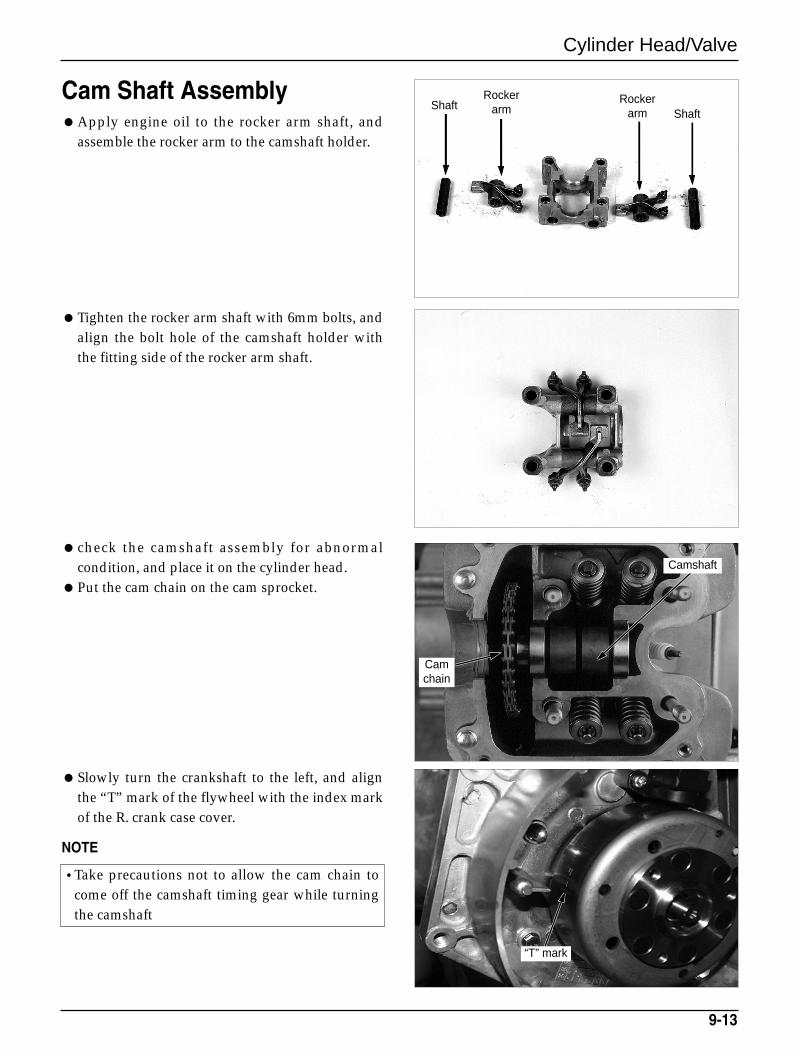
“T” mark
Cylinder Head/Valve
Cam Shaft AssemblyApply engine oil to the rocker arm shaft, and
assemble the rocker arm to the camshaft holder.
Tighten the rocker arm shaft with 6mm bolts, andalign the bolt hole of the camshaft holder withthe fitting side of the rocker arm shaft.
check the camshaft assembly for abnormalcondition, and place it on the cylinder head.
Put the cam chain on the cam sprocket.
Slowly turn the crankshaft to the left, and alignthe “T” mark of the flywheel with the index markof the R. crank case cover.
NOTE
9-13
•Take precautions not to allow the cam chain tocome off the camshaft timing gear while turningthe camshaft
ShaftShaft
Rockerarm
Rockerarm
Camshaft
Camchain
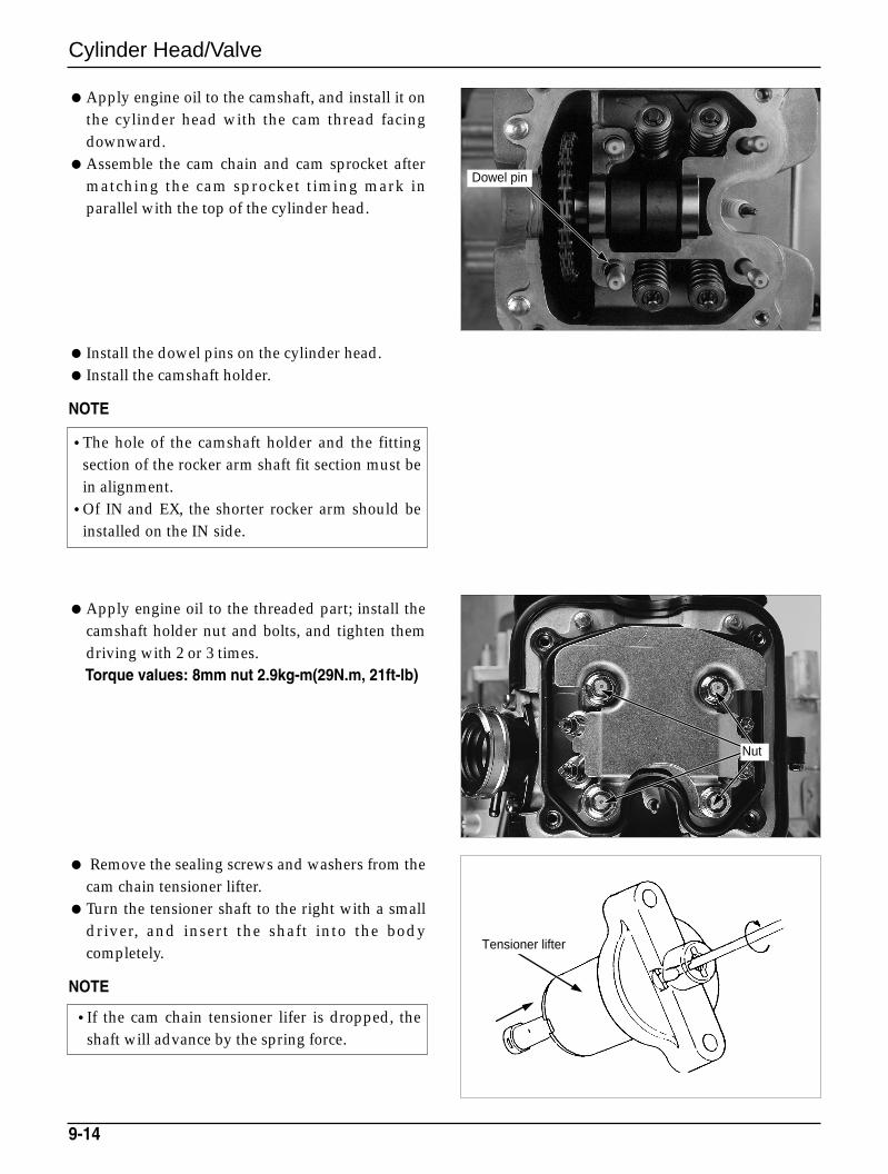
Cylinder Head/Valve
Apply engine oil to the camshaft, and install it onthe cylinder head with the cam thread facingdownward.
Assemble the cam chain and cam sprocket aftermatching the cam sprocket timing mark inparallel with the top of the cylinder head.
Install the dowel pins on the cylinder head. Install the camshaft holder.
NOTE
Apply engine oil to the threaded part; install thecamshaft holder nut and bolts, and tighten themdriving with 2 or 3 times.Torque values: 8mm nut 2.9kg-m(29N.m, 21ft-lb)
Remove the sealing screws and washers from thecam chain tensioner lifter.
Turn the tensioner shaft to the right with a smalldriver, and insert the shaft into the bodycompletely.
NOTE
9-14
•The hole of the camshaft holder and the fittingsection of the rocker arm shaft fit section must bein alignment.
•Of IN and EX, the shorter rocker arm should beinstalled on the IN side.
•If the cam chain tensioner lifer is dropped, theshaft will advance by the spring force.
Dowel pin
Tensioner lifter
Nut
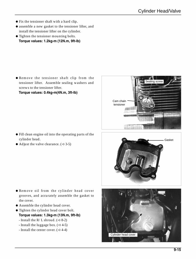
Cylinder Head/Valve
Fix the tensioner shaft with a hard clip.assemble a new gasket to the tensioner lifter, and
install the tensioner lifter on the cylinder.Tighten the tensioner mounting bolts.
Torque values: 1.2kg-m (12N.m, 9ft-lb)
Remove the tensioner shaft clip from thetensioner lifter. Assemble sealing washers andscrews to the tensioner lifter.Torque values: 0.4kg-m(4N.m, 3ft-lb)
Fill clean engine oil into the operating parts of thecylinder head.
Adjust the valve clearance. ( 3-5)
Remove oil from the cylinder head covergrooves, and accurately assemble the gasket tothe cover.
Assemble the cylinder head cover.Tighten the cylinder head cover bolt.
Torque values: 1.3kg-m (13N.m, 9ft-lb)- Install the R/L shroud. ( 8-2)- Install the luggage box. ( 4-5)- Install the center cover. ( 4-4)
9-15
Cylinder head cover
Sealing screw
Cam chaintensioner
Gasket
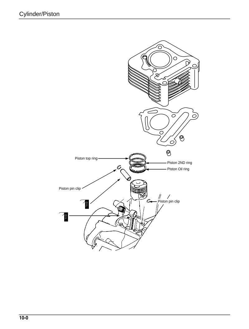
Cylinder/Piston
10-0
OIL
OIL
Piston pin clip
Piston top ring
Piston pin clip
Piston 2ND ring
Piston Oil ring
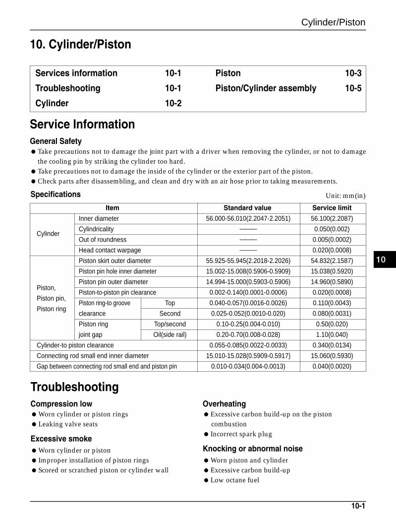
Cylinder/Piston
10-1
10. Cylinder/Piston
Services information 10-1
Troubleshooting 10-1
Cylinder 10-2
Piston 10-3
Piston/Cylinder assembly 10-5
Service InformationGeneral SafetyTake precautions not to damage the joint part with a driver when removing the cylinder, or not to damage
the cooling pin by striking the cylinder too hard.Take precautions not to damage the inside of the cylinder or the exterior part of the piston.Check parts after disassembling, and clean and dry with an air hose prior to taking measurements.
TroubleshootingCompression lowWorn cylinder or piston ringsLeaking valve seats
Excessive smokeWorn cylinder or piston Improper installation of piston ringsScored or scratched piston or cylinder wall
OverheatingExcessive carbon build-up on the piston
combustion Incorrect spark plug
Knocking or abnormal noiseWorn piston and cylinderExcessive carbon build-up Low octane fuel
Item Standard value Service limit
Inner diameter 56.000-56.010(2.2047-2.2051) 56.100(2.2087)
CylinderCylindricality 0.050(0.002)
Out of roundness 0.005(0.0002)
Head contact warpage 0.020(0.0008)
Piston skirt outer diameter 55.925-55.945(2.2018-2.2026) 54.832(2.1587)
Piston pin hole inner diameter 15.002-15.008(0.5906-0.5909) 15.038(0.5920)
Piston pin outer diameter 14.994-15.000(0.5903-0.5906) 14.960(0.5890)Piston,
Piston-to-piston pin clearance 0.002-0.140(0.0001-0.0006) 0.020(0.0008)Piston pin,
Piston ring-to groove Top 0.040-0.057(0.0016-0.0026) 0.110(0.0043)Piston ring
clearance Second 0.025-0.052(0.0010-0.020) 0.080(0.0031)
Piston ring Top/second 0.10-0.25(0.004-0.010) 0.50(0.020)
joint gap Oil(side rail) 0.20-0.70(0.008-0.028) 1.10(0.040)
Cylinder-to piston clearance 0.055-0.085(0.0022-0.0033) 0.340(0.0134)
Connecting rod small end inner diameter 15.010-15.028(0.5909-0.5917) 15.060(0.5930)
Gap between connecting rod small end and piston pin 0.010-0.034(0.004-0.0013) 0.040(0.0020)
Specifications Unit: mm(in)
10
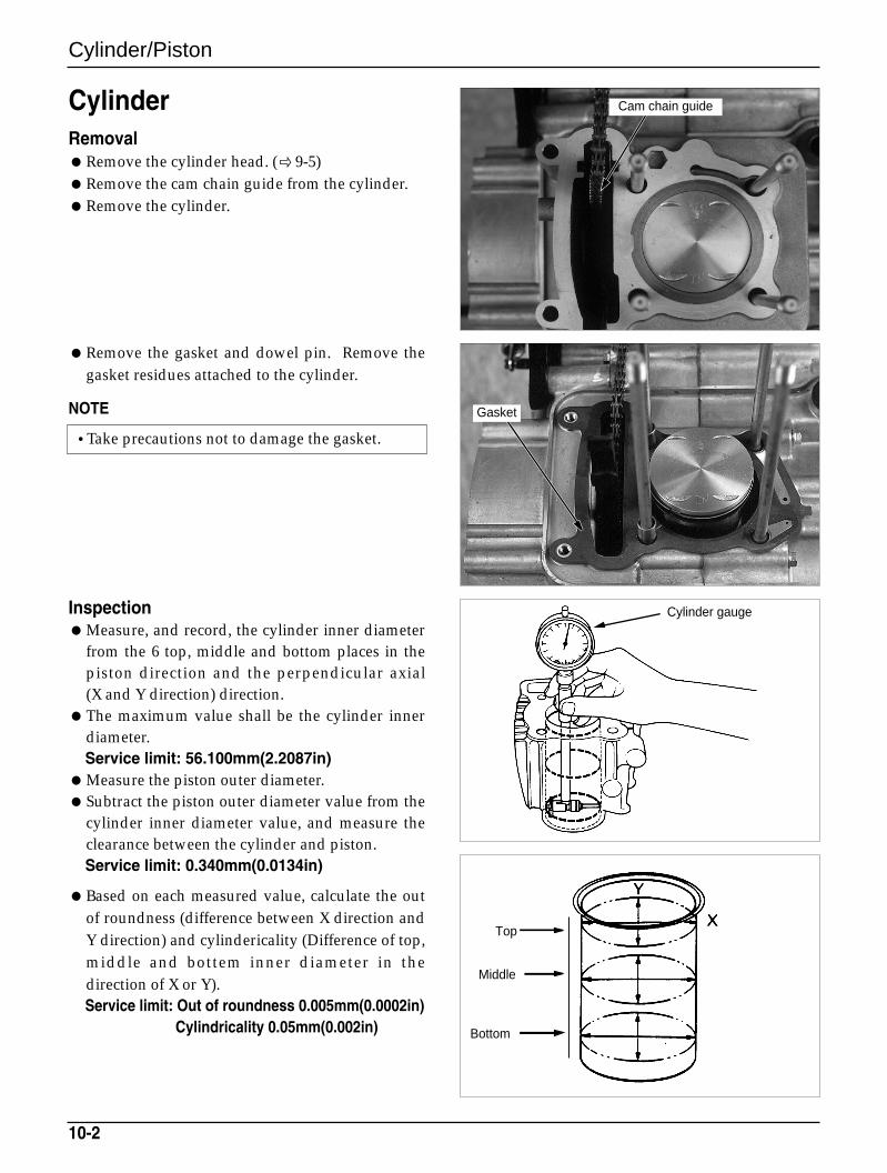
Cylinder/Piston
CylinderRemovalRemove the cylinder head. (9-5)Remove the cam chain guide from the cylinder.Remove the cylinder.
Remove the gasket and dowel pin. Remove thegasket residues attached to the cylinder.
NOTE
InspectionMeasure, and record, the cylinder inner diameter
from the 6 top, middle and bottom places in thepiston direction and the perpendicular axial (X and Y direction) direction.
The maximum value shall be the cylinder innerdiameter.Service limit: 56.100mm(2.2087in)
Measure the piston outer diameter.Subtract the piston outer diameter value from the
cylinder inner diameter value, and measure theclearance between the cylinder and piston.Service limit: 0.340mm(0.0134in)
Based on each measured value, calculate the outof roundness (difference between X direction andY direction) and cylindericality (Difference of top,middle and bottem inner diameter in thedirection of X or Y).Service limit: Out of roundness 0.005mm(0.0002in)
Cylindricality 0.05mm(0.002in)
10-2
•Take precautions not to damage the gasket.
Cam chain guide
Gasket
Cylinder gauge
Top
Middle
Bottom
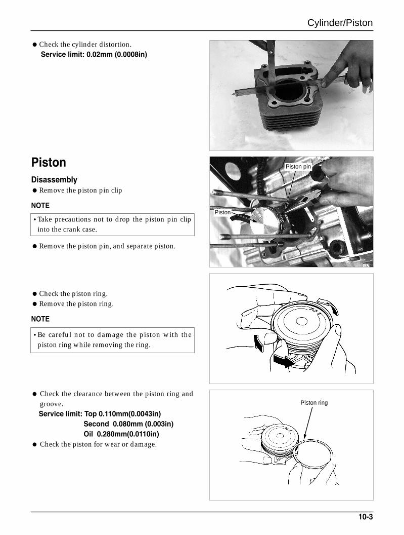
Cylinder/Piston
Check the cylinder distortion.Service limit: 0.02mm (0.0008in)
PistonDisassemblyRemove the piston pin clip
NOTE
Remove the piston pin, and separate piston.
Check the piston ring.Remove the piston ring.
NOTE
Check the clearance between the piston ring andgroove.Service limit: Top 0.110mm(0.0043in)
Second 0.080mm (0.003in) Oil 0.280mm(0.0110in)
Check the piston for wear or damage.
10-3
•Take precautions not to drop the piston pin clipinto the crank case.
•Be careful not to damage the piston with thepiston ring while removing the ring.
Piston pin
Piston
Piston ring
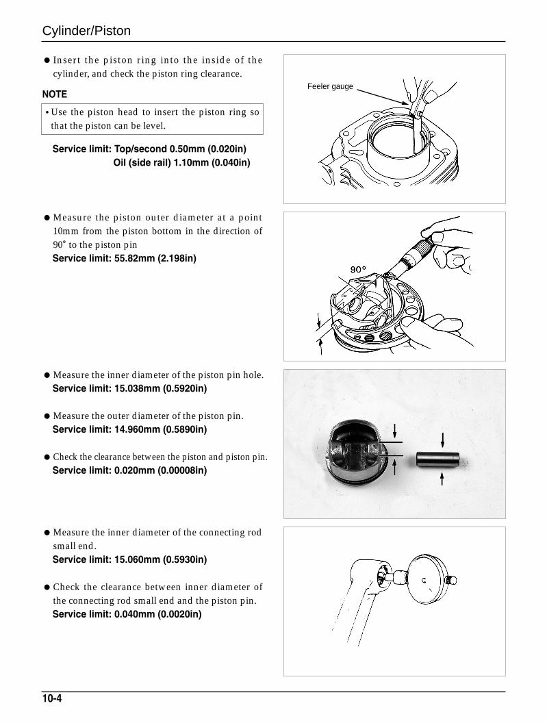
Cylinder/Piston
Insert the piston ring into the inside of thecylinder, and check the piston ring clearance.
NOTE
Service limit: Top/second 0.50mm (0.020in)Oil (side rail) 1.10mm (0.040in)
Measure the piston outer diameter at a point10mm from the piston bottom in the direction of90。to the piston pinService limit: 55.82mm (2.198in)
Measure the inner diameter of the piston pin hole.Service limit: 15.038mm (0.5920in)
Measure the outer diameter of the piston pin.Service limit: 14.960mm (0.5890in)
Check the clearance between the piston and piston pin.Service limit: 0.020mm (0.00008in)
Measure the inner diameter of the connecting rodsmall end.Service limit: 15.060mm (0.5930in)
Check the clearance between inner diameter ofthe connecting rod small end and the piston pin.Service limit: 0.040mm (0.0020in)
10-4
•Use the piston head to insert the piston ring sothat the piston can be level.
Feeler gauge
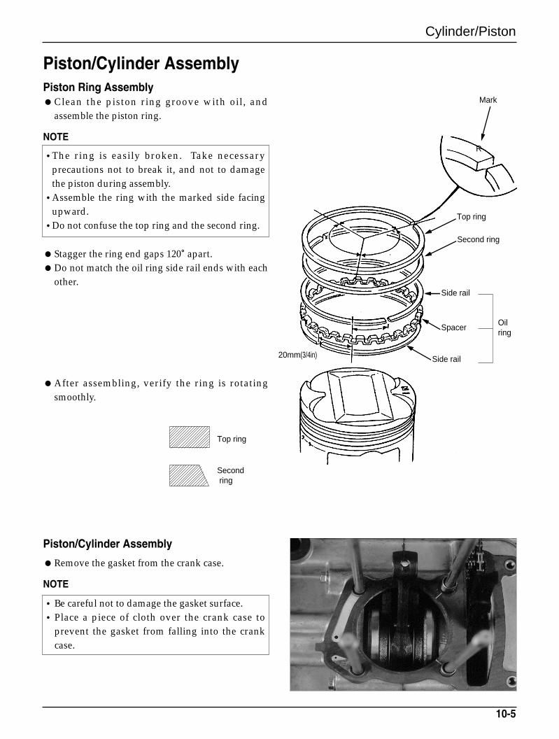
Cylinder/Piston
Piston/Cylinder AssemblyPiston Ring AssemblyClean the piston ring groove with oil, and
assemble the piston ring.
NOTE
Stagger the ring end gaps 120。apart.Do not match the oil ring side rail ends with each
other.
Piston/Cylinder Assembly
Remove the gasket from the crank case.
NOTE
After assembling, verify the ring is rotatingsmoothly.
10-5
Top ring
Secondring
•The ring is easily broken. Take necessaryprecautions not to break it, and not to damagethe piston during assembly.
•Assemble the ring with the marked side facingupward.
•Do not confuse the top ring and the second ring.
•Be careful not to damage the gasket surface.•Place a piece of cloth over the crank case to
prevent the gasket from falling into the crankcase.
20mm(3/4in) Side rail
SpacerOilring
Side rail
Second ring
Top ring
Mark
R
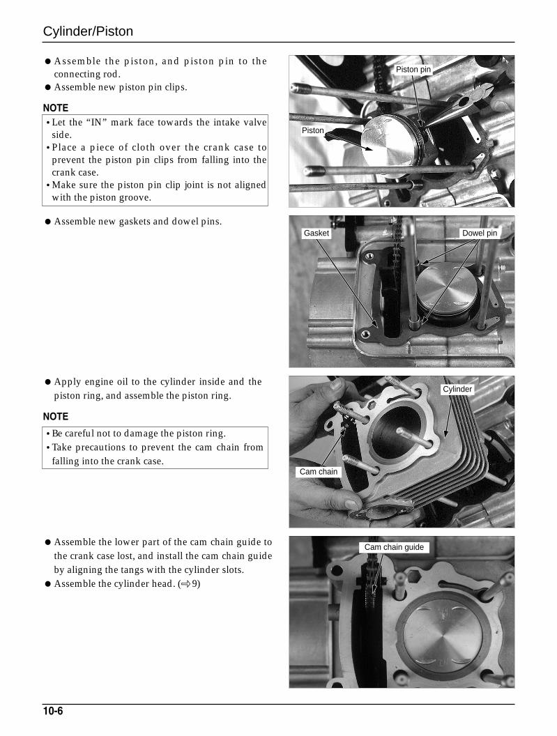
Cylinder/Piston
Assemble the piston, and piston pin to theconnecting rod.
Assemble new piston pin clips.
NOTE
Assemble new gaskets and dowel pins.
Apply engine oil to the cylinder inside and thepiston ring, and assemble the piston ring.
NOTE
Assemble the lower part of the cam chain guide tothe crank case lost, and install the cam chain guideby aligning the tangs with the cylinder slots.
Assemble the cylinder head. ( 9)
10-6
•Let the “IN” mark face towards the intake valveside.
•Place a piece of cloth over the crank case toprevent the piston pin clips from falling into thecrank case.
•Make sure the piston pin clip joint is not alignedwith the piston groove.
•Be careful not to damage the piston ring.•Take precautions to prevent the cam chain from
falling into the crank case.
Piston pin
Piston
Gasket Dowel pin
Cylinder
Cam chain
Cam chain guide

MEMO
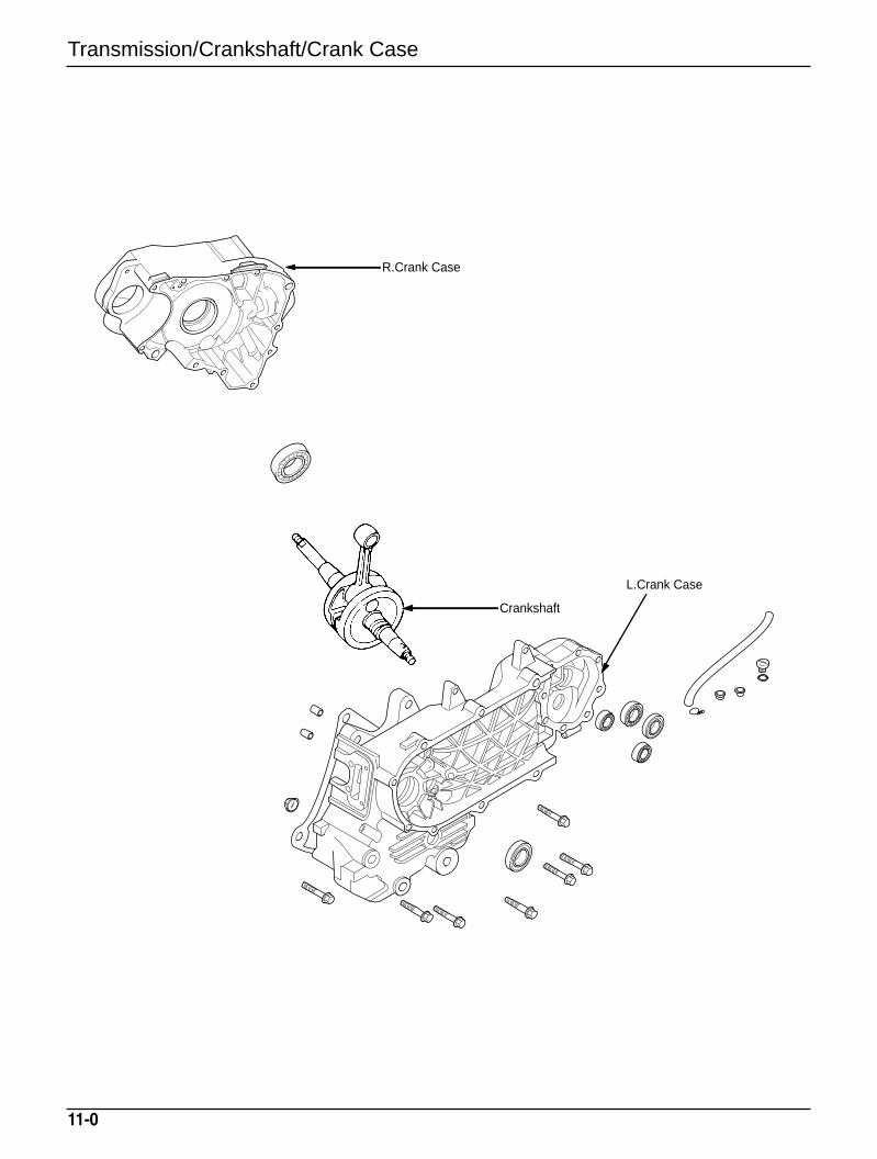
Transmission/Crankshaft/Crank Case
11-0
R.Crank Case
Crankshaft
L.Crank Case
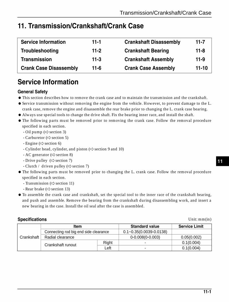
Transmission/Crankshaft/Crank Case
Service InformationGeneral SafetyThis section describes how to remove the crank case and to maintain the transmission and the crankshaft.Service transmission without removing the engine from the vehicle. However, to prevent damage to the L.
crank case, remove the engine and disassemble the rear brake prior to changing the L. crank case bearing.Always use special tools to change the drive shaft. Fix the bearing inner race, and install the shaft.The following parts must be removed prior to removing the crank case. Follow the removal procedure
specified in each section.- Oil pump ( section 3)- Carburetor ( section 5)- Engine ( section 6)- Cylinder head, cylinder, and piston ( section 9 and 10)- AC generator ( section 8)- Drive pulley ( section 7)- Clutch / driven pulley ( section 7)
The following parts must be removed prior to changing the L. crank case. Follow the removal procedurespecified in each section.- Transmission ( section 11)- Rear brake ( section 13)
To assemble the crank case and crankshaft, set the special tool to the inner race of the crankshaft bearing,and push and assemble. Remove the bearing from the crankshaft during disassembling work, and insert anew bearing in the case. Install the oil seal after the case is assembled.
Specifications
11-1
11. Transmission/Crankshaft/Crank Case
Service Information 11-1
Troubleshooting 11-2
Transmission 11-3
Crank Case Disassembly 11-6
Crankshaft Disassembly 11-7
Crankshaft Bearing 11-8
Crankshaft Assembly 11-9
Crank Case Assembly 11-10
Item Standard value Service LimitConnecting rod big end side clearance 0.1~0.35(0.0039-0.0138)
Crankshaft Radial clearance 0-0.008(0-0.003) 0.05(0.002)
Crankshaft runout Right - 0.1(0.004)Left - 0.1(0.004)
Unit: mm(in)
11
Transmission/Crankshaft/Crank Case
Torque valueCrank case bolt 1.0kg-m(10N.m, 7ft-lb)
Tools- Universal bearing puller- Bearing remover set- Remover assembly- Remover shaft- Remover head- Sliding weight- Assembly shaft
Troubleshooting
Engine noiseConnecting rod big and small ends loose.Crank pin bearing loose.
Engine started but unable to move outTransmission damaged.Transmission seized.
Noise during operationGear worn, overheated, or cracked.Bearing worn.
Oil leaksExcessive oil levelOil seal worn or damaged.
11-2
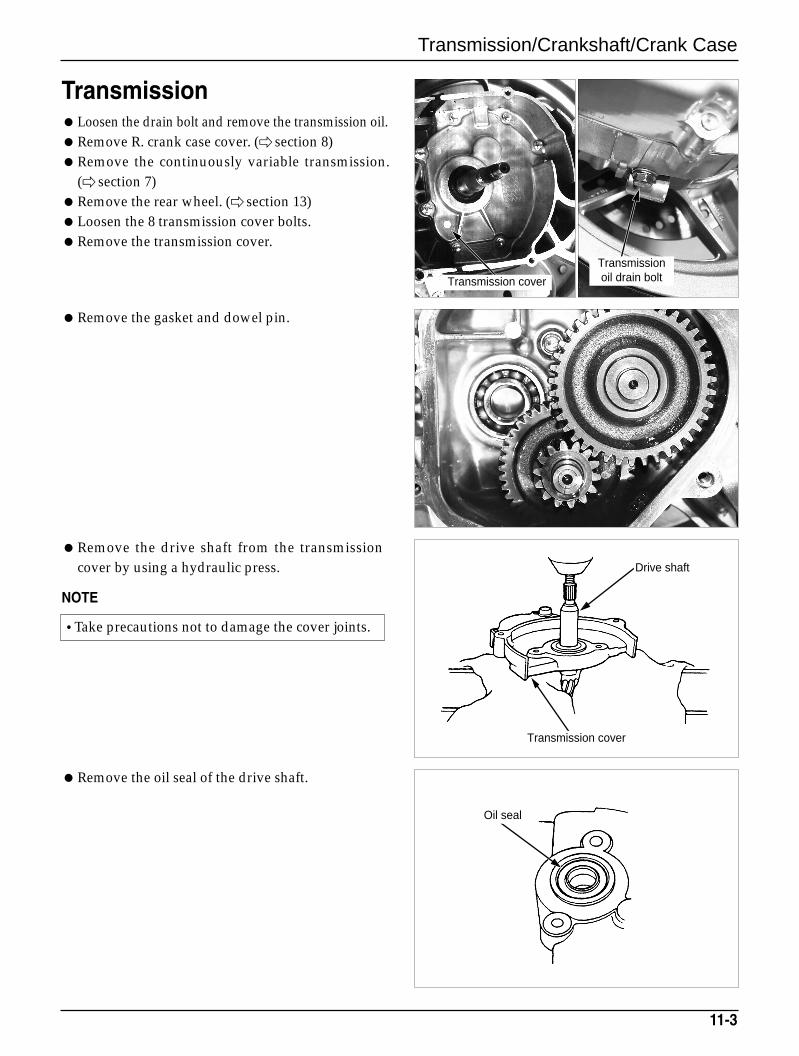
Transmission/Crankshaft/Crank Case
TransmissionLoosen the drain bolt and remove the transmission oil.Remove R. crank case cover. ( section 8)Remove the continuously variable transmission.
( section 7)Remove the rear wheel. ( section 13)Loosen the 8 transmission cover bolts.Remove the transmission cover.
Remove the gasket and dowel pin.
Remove the drive shaft from the transmissioncover by using a hydraulic press.
NOTE
Remove the oil seal of the drive shaft.
11-3
•Take precautions not to damage the cover joints.
Transmissionoil drain boltTransmission cover
Drive shaft
Transmission cover
Oil seal
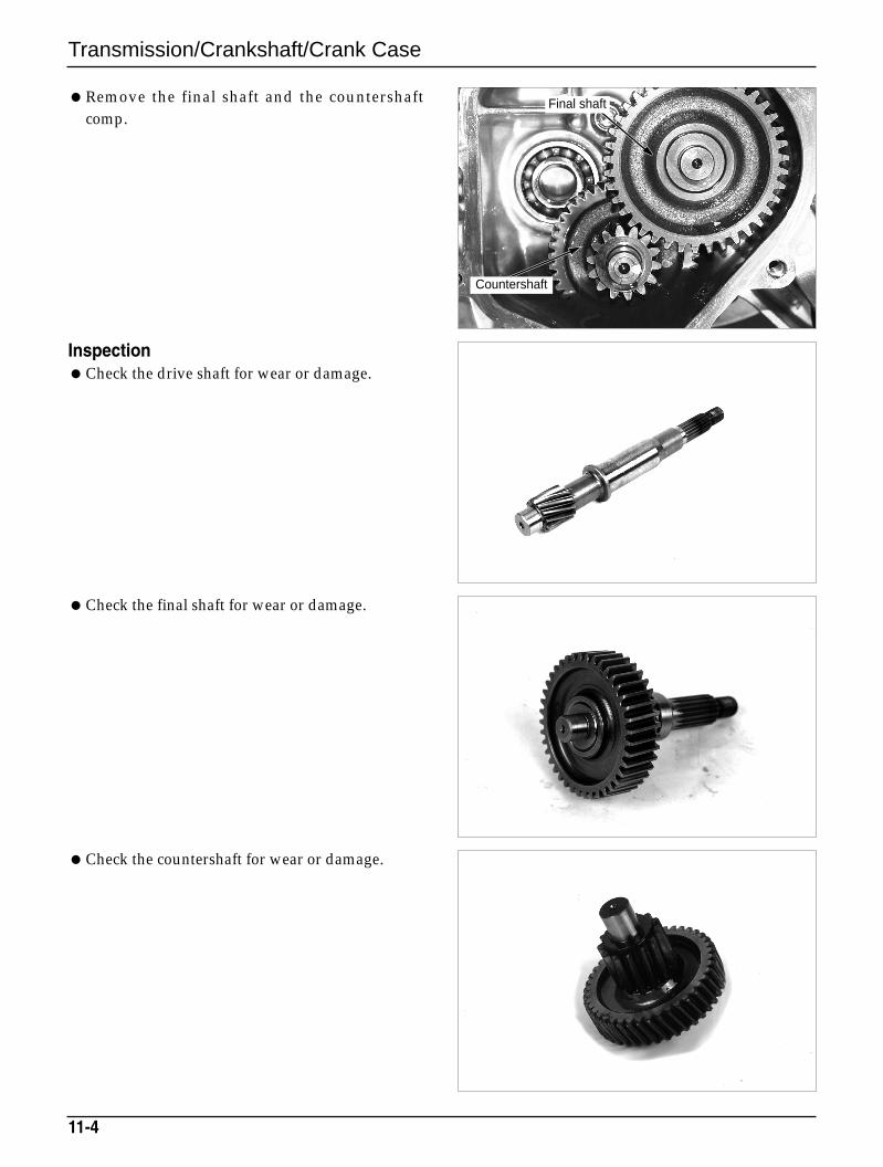
Transmission/Crankshaft/Crank Case
Check the final shaft for wear or damage.
Check the countershaft for wear or damage.
Remove the final shaft and the countershaftcomp.
InspectionCheck the drive shaft for wear or damage.
11-4
Final shaft
Countershaft
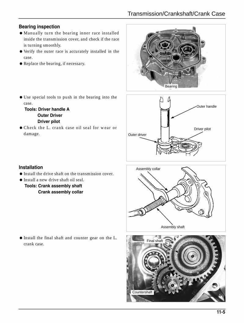
Transmission/Crankshaft/Crank Case
Bearing inspectionManually turn the bearing inner race installed
inside the transmission cover, and check if the raceis turning smoothly.
Verify the outer race is accurately installed in thecase.
Replace the bearing, if necessary.
Use special tools to push in the bearing into thecase.Tools: Driver handle A
Outer DriverDriver pilot
Check the L. crank case oil seal for wear ordamage.
11-5
Installation Install the drive shaft on the transmission cover. Install a new drive shaft oil seal.
Tools: Crank assembly shaftCrank assembly collar
Install the final shaft and counter gear on the L.crank case.
Final shaft
Countershaft
Bearing
Outer handle
Driver pilot
Outer driver
Assembly collar
Assembly shaft
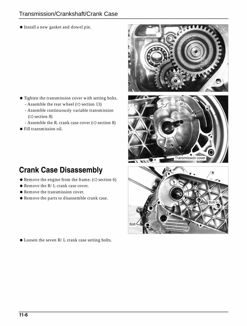
Transmission/Crankshaft/Crank Case
Crank Case DisassemblyRemove the engine from the frame. ( section 6)Remove the R/L crank case cover.Remove the transmission cover.Remove the parts to disassemble crank case.
Loosen the seven R/L crank case setting bolts.
Install a new gasket and dowel pin.
Tighten the transmission cover with setting bolts.- Assemble the rear wheel ( section 13)- Assemble continuously variable transmission
( section 8)- Assemble the R. crank case cover ( section 8)
Fill transmission oil.
11-6
Transmission cover
Bolt
Bolt
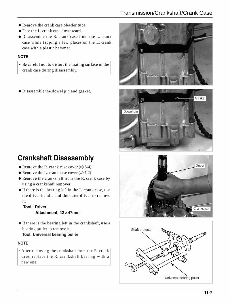
Transmission/Crankshaft/Crank Case
Remove the crank case bleeder tube.Face the L. crank case downward.Disassemble the R. crank case from the L. crank
case while tapping a few places on the L. crankcase with a plastic hammer.
NOTE
Disassemble the dowel pin and gasket.
11-7
•Be careful not to distort the mating surface of thecrank case during disassembly.
Crankshaft DisassemblyRemove the R. crank case cover.(8-4)Remove the L. crank case cover.( 7-2)Remove the crankshaft from the R. crank case by
using a crankshaft remover. If there is the bearing left in the L. crank case, use
the driver handle and the outer driver to removeit.Tool : Driver
Attachment, 42××47mm
If there is the bearing left in the crankshaft, use abearing puller to remove it.Tool: Universal bearing puller
NOTE
•After removing the crankshaft from the R. crankcase, replace the R. crankshaft bearing with anew one.
Dowel pin
Gasket
Crankshaft
Shaft protector
Universal bearing puller
Driver
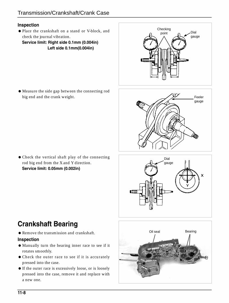
Transmission/Crankshaft/Crank Case
Check the vertical shaft play of the connectingrod big end from the X and Y direction.Service limit: 0.05mm (0.002in)
Crankshaft BearingRemove the transmission and crankshaft.
InspectionManually turn the bearing inner race to see if it
rotates smoothly.Check the outer race to see if it is accurately
pressed into the case. If the outer race is excessively loose, or is loosely
pressed into the case, remove it and replace witha new one.
InspectionPlace the crankshaft on a stand or V-block, and
check the journal vibration.Service limit: Right side 0.1mm (0.004in)
Left side 0.1mm(0.004in)
Measure the side gap between the connecting rodbig end and the crank weight.
11-8
Oil seal Bearing
Checkingpoint Dial
gauge
Feelergauge
Dial gauge
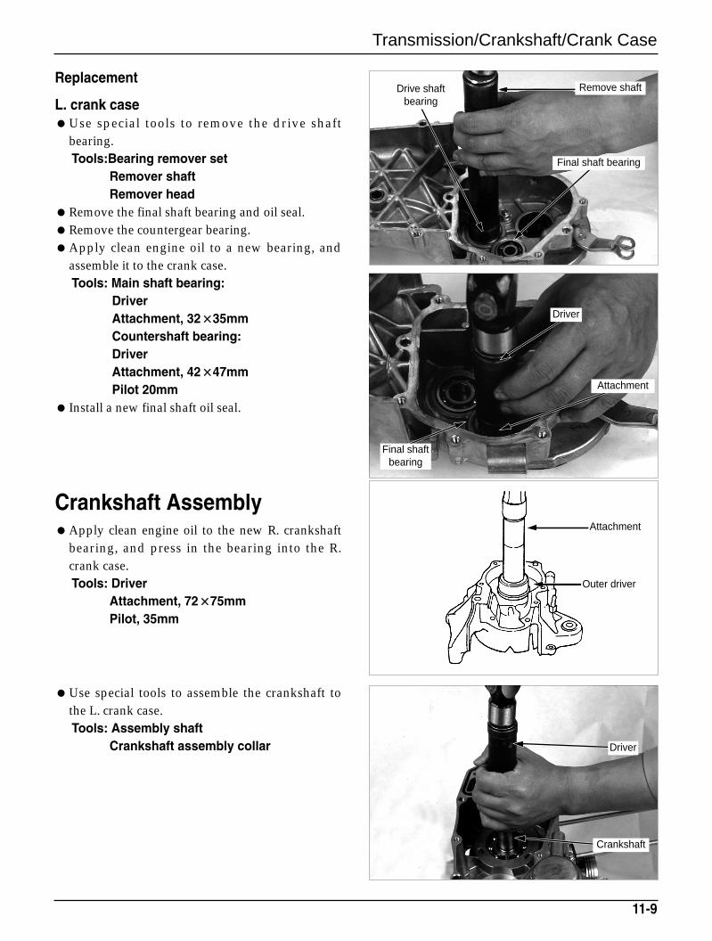
Transmission/Crankshaft/Crank Case
Replacement
L. crank caseUse special tools to remove the drive shaft
bearing.Tools:Bearing remover set
Remover shaftRemover head
Remove the final shaft bearing and oil seal.Remove the countergear bearing.Apply clean engine oil to a new bearing, and
assemble it to the crank case.Tools: Main shaft bearing:
DriverAttachment, 32××35mmCountershaft bearing:DriverAttachment, 42××47mmPilot 20mm
Install a new final shaft oil seal.
11-9
Crankshaft Assembly Apply clean engine oil to the new R. crankshaft
bearing, and press in the bearing into the R.crank case.Tools: Driver
Attachment, 72××75mmPilot, 35mm
Use special tools to assemble the crankshaft tothe L. crank case.Tools: Assembly shaft
Crankshaft assembly collar
Crankshaft
Driver
Remove shaft
Final shaft bearing
Drive shaftbearing
Driver
Attachment
Attachment
Outer driver
Final shaft bearing
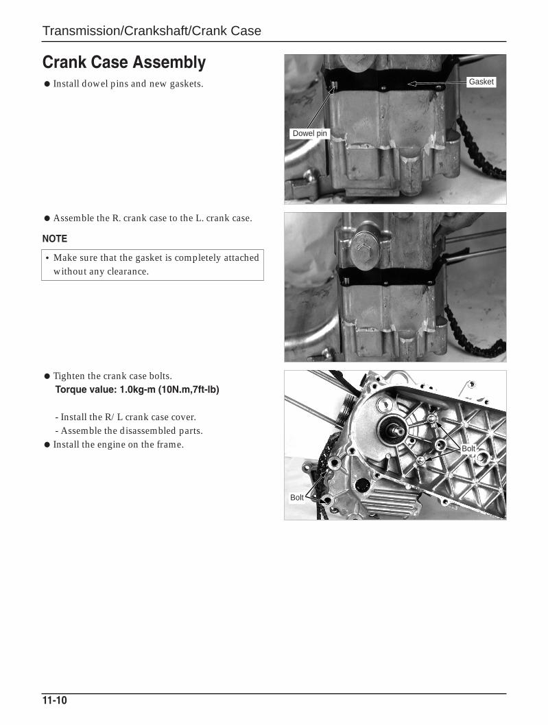
Transmission/Crankshaft/Crank Case
Crank Case Assembly Install dowel pins and new gaskets.
Assemble the R. crank case to the L. crank case.
NOTE
Tighten the crank case bolts.Torque value: 1.0kg-m (10N.m,7ft-lb)
- Install the R/L crank case cover.- Assemble the disassembled parts.
Install the engine on the frame.
11-10
•Make sure that the gasket is completely attachedwithout any clearance.
Bolt
Bolt
Dowel pin
Gasket
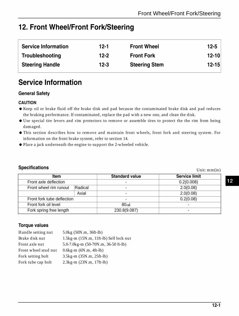
Front Wheel/Front Fork/Steering
12-1
12. Front Wheel/Front Fork/Steering
Service Information 12-1
Troubleshooting 12-2
Steering Handle 12-3
Front Wheel 12-5
Front Fork 12-10
Steering Stem 12-15
Service InformationGeneral Safety
CAUTIONKeep oil or brake fluid off the brake disk and pad because the contaminated brake disk and pad reduces
the braking performance. If contaminated, replace the pad with a new one, and clean the disk.Use special tire levers and rim protectors to remove or assemble tires to protect the the rim from being
damaged.This section describes how to remove and maintain front wheels, front fork and steering system. For
information on the front brake system, refer to section 14.Place a jack underneath the engine to support the 2-wheeled vehicle.
Item Standard value Service limitFront axle deflection - 0.2(0.008)Front wheel rim runout Radical - 2.0(0.08)
Axial - 2.0(0.08)Front fork tube deflection - 0.2(0.08)Front fork oil level 80 -Fork spring free length 230.8(9.087) -
Specifications Unit: mm(in)
Torque valuesHandle setting nut 5.0kg (50N.m, 36ft-lb)Brake disk nut 1.5kg-m (15N.m, 11ft-lb) Self lock nutFront axle nut 5.0-7.0kg-m (50-70N.m, 36-50 ft-lb)Front wheel stud nut 0.6kg-m (6N.m, 4ft-lb)Fork setting bolt 3.5kg-m (35N.m, 25ft-lb)Fork tube cap bolt 2.3kg-m (23N.m, 17ft-lb)
12
Front Wheel/Front Fork/Steering
Troubleshooting
Hard steeringSteering bearing adjustment nut too tightFaulty steering stem bearingsDamaged steering stem bearings Insufficient tire pressure
Steers to one side or does not track straightUnevenly adjusted right and left shock absorbersBent front forksBent front axle: wheel installed incorrectly
Front wheel wobblingBent rimWorn front wheel bearingsFaulty tireAxle nut not tightened properlyWheel out of balance
Soft suspensionWeak fork springs Insufficient fluid in front forks
Hard suspension Incorrect fluid weight in front forksFront fork air pressure incorrectBent fork tubesClogged fluid passageClogged anti-dive orifice
Front suspension noiseWorn slider or guide bushings Insufficient fluid in forksLoose front fork fastenersLack of grease in speedometer gearbox
12-2
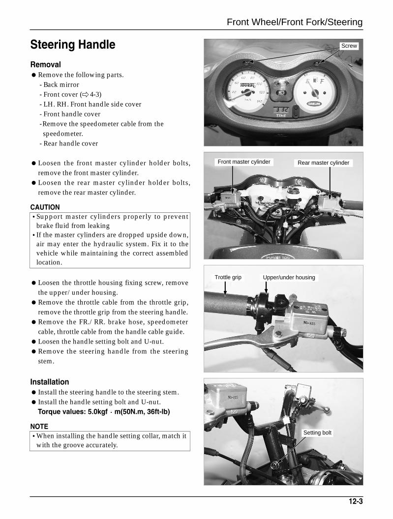
Front Wheel/Front Fork/Steering
Steering Handle
RemovalRemove the following parts.
- Back mirror- Front cover ( 4-3)- LH. RH. Front handle side cover- Front handle cover-Remove the speedometer cable from the
speedometer.- Rear handle cover
Loosen the front master cylinder holder bolts,remove the front master cylinder.
Loosen the rear master cylinder holder bolts,remove the rear master cylinder.
CAUTION•Support master cylinders properly to prevent
brake fluid from leaking•If the master cylinders are dropped upside down,
air may enter the hydraulic system. Fix it to thevehicle while maintaining the correct assembledlocation.
Loosen the throttle housing fixing screw, removethe upper/under housing.
Remove the throttle cable from the throttle grip,remove the throttle grip from the steering handle.
Remove the FR./RR. brake hose, speedometercable, throttle cable from the handle cable guide.
Loosen the handle setting bolt and U-nut.Remove the steering handle from the steering
stem.
Installation Install the steering handle to the steering stem. Install the handle setting bolt and U-nut.
Torque values: 5.0kgf m(50N.m, 36ft-lb)
NOTE•When installing the handle setting collar, match it
with the groove accurately.
12-3
Screw
Front master cylinder
Trottle grip
Rear master cylinder
Upper/under housing
Setting bolt
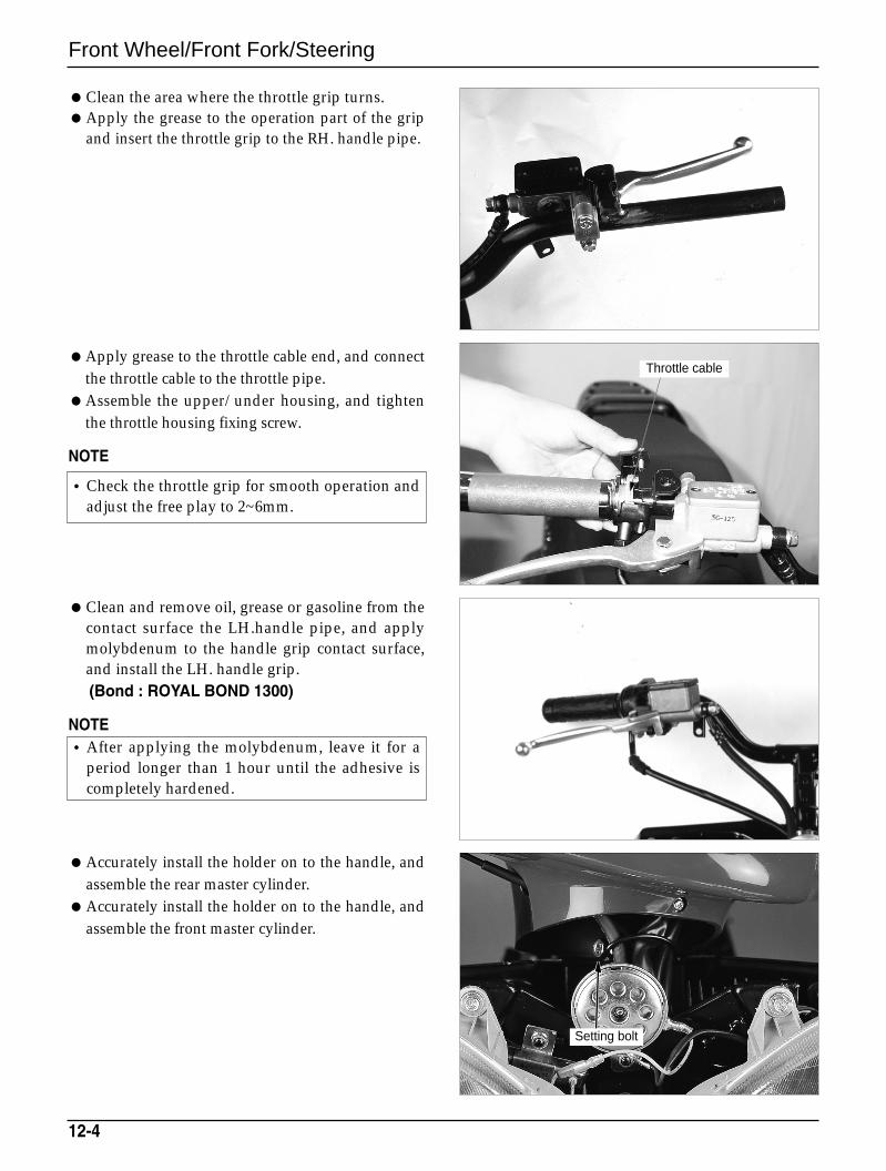
Front Wheel/Front Fork/Steering
Clean the area where the throttle grip turns.Apply the grease to the operation part of the grip
and insert the throttle grip to the RH. handle pipe.
Apply grease to the throttle cable end, and connectthe throttle cable to the throttle pipe.
Assemble the upper/under housing, and tightenthe throttle housing fixing screw.
NOTE
Clean and remove oil, grease or gasoline from thecontact surface the LH.handle pipe, and applymolybdenum to the handle grip contact surface,and install the LH. handle grip.(Bond : ROYAL BOND 1300)
NOTE
Accurately install the holder on to the handle, andassemble the rear master cylinder.
Accurately install the holder on to the handle, andassemble the front master cylinder.
12-4
•Check the throttle grip for smooth operation andadjust the free play to 2~6mm.
•After applying the molybdenum, leave it for aperiod longer than 1 hour until the adhesive iscompletely hardened.
Setting bolt
Throttle cable
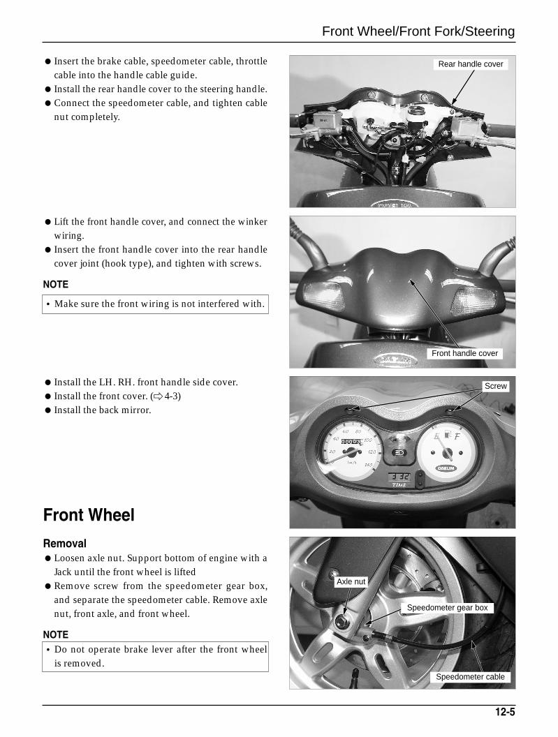
Front Wheel/Front Fork/Steering
Insert the brake cable, speedometer cable, throttlecable into the handle cable guide.
Install the rear handle cover to the steering handle.Connect the speedometer cable, and tighten cable
nut completely.
Lift the front handle cover, and connect the winkerwiring.
Insert the front handle cover into the rear handlecover joint (hook type), and tighten with screws.
NOTE
Install the LH. RH. front handle side cover. Install the front cover. ( 4-3) Install the back mirror.
Front Wheel
RemovalLoosen axle nut. Support bottom of engine with a
Jack until the front wheel is liftedRemove screw from the speedometer gear box,
and separate the speedometer cable. Remove axlenut, front axle, and front wheel.
NOTE
12-5
•Make sure the front wiring is not interfered with.
•Do not operate brake lever after the front wheelis removed.
Rear handle cover
Front handle cover
Speedometer cable
Speedometer gear box
Axle nut
Screw
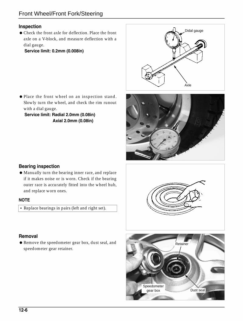
Front Wheel/Front Fork/Steering
InspectionCheck the front axle for deflection. Place the front
axle on a V-block, and measure deflection with adial gauge.Service limit: 0.2mm (0.008in)
Place the front wheel on an inspection stand.Slowly turn the wheel, and check the rim runoutwith a dial gauge.Service limit: Radial 2.0mm (0.08in)
Axial 2.0mm (0.08in)
Bearing inspectionManually turn the bearing inner race, and replace
if it makes noise or is worn. Check if the bearingouter race is accurately fitted into the wheel hub,and replace worn ones.
NOTE
RemovalRemove the speedometer gear box, dust seal, and
speedometer gear retainer.
12-6
•Replace bearings in pairs (left and right set).
Retainer
Dust sealSpeedometer
gear box
Didal gauge
Axle
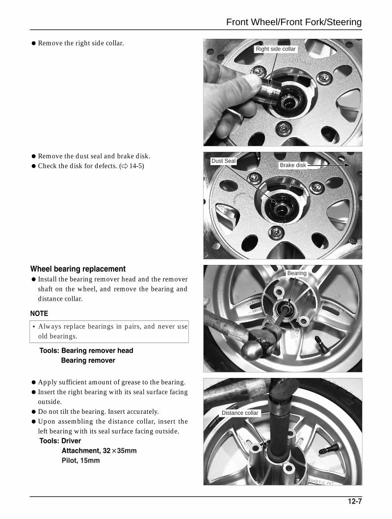
Front Wheel/Front Fork/Steering
Remove the right side collar.
Remove the dust seal and brake disk.Check the disk for defects. (14-5)
Wheel bearing replacement Install the bearing remover head and the remover
shaft on the wheel, and remove the bearing anddistance collar.
NOTE
Tools: Bearing remover headBearing remover
Apply sufficient amount of grease to the bearing. Insert the right bearing with its seal surface facing
outside. Do not tilt the bearing. Insert accurately.Upon assembling the distance collar, insert the
left bearing with its seal surface facing outside.Tools: Driver
Attachment, 32××35mmPilot, 15mm
12-7
•Always replace bearings in pairs, and never useold bearings.
Right side collar
Brake diskDust Seal
Bearing
Distance collar
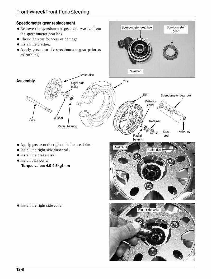
Front Wheel/Front Fork/Steering
Speedometer gear replacementRemove the speedometer gear and washer from
the speedometer gear box.Check the gear for wear or damage. Install the washer.Apply grease to the speedometer gear prior to
assembling.
Assembly
Apply grease to the right side dust seal rim. Install the right side dust seal. Install the brake disk. Install disk bolts.
Torque value: 4.0-4.5kgf m
Install the right side collar.
12-8
Right side collar
Dust Seal
Axle
Brake disc
Right sidecollar
Tire
Rim
Distancecollar
Speedometer gear box
Retainer
Radialbearing
Dustseal
Axle nut
Oil seal
Radial bearing
Brake diskDust Seal
Speedometer gear box Speedometergear
Washer
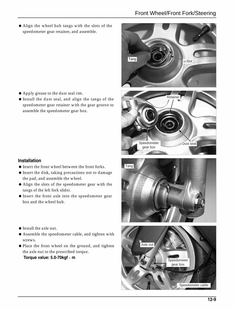
Front Wheel/Front Fork/Steering
Align the wheel hub tangs with the slots of thespeedometer gear retainer, and assemble.
Apply grease to the dust seal rim. Install the dust seal, and align the tangs of the
speedometer gear retainer with the gear groove toassemble the speedometer gear box.
Installation Insert the front wheel between the front forks. Insert the disk, taking precautions not to damage
the pad, and assemble the wheel.Align the slots of the speedometer gear with the
tangs of the left fork slider. Insert the front axle into the speedometer gear
box and the wheel hub.
Install the axle nut.Assemble the speedometer cable, and tighten with
screws.Place the front wheel on the ground, and tighten
the axle nut to the prescribed torque.Torque value: 5.0-70kgf m
12-9
TangSlot
Retainer
Dust sealSpeedometergear box
Tang
Speedometer cable
Speedometergear box
Axle nut
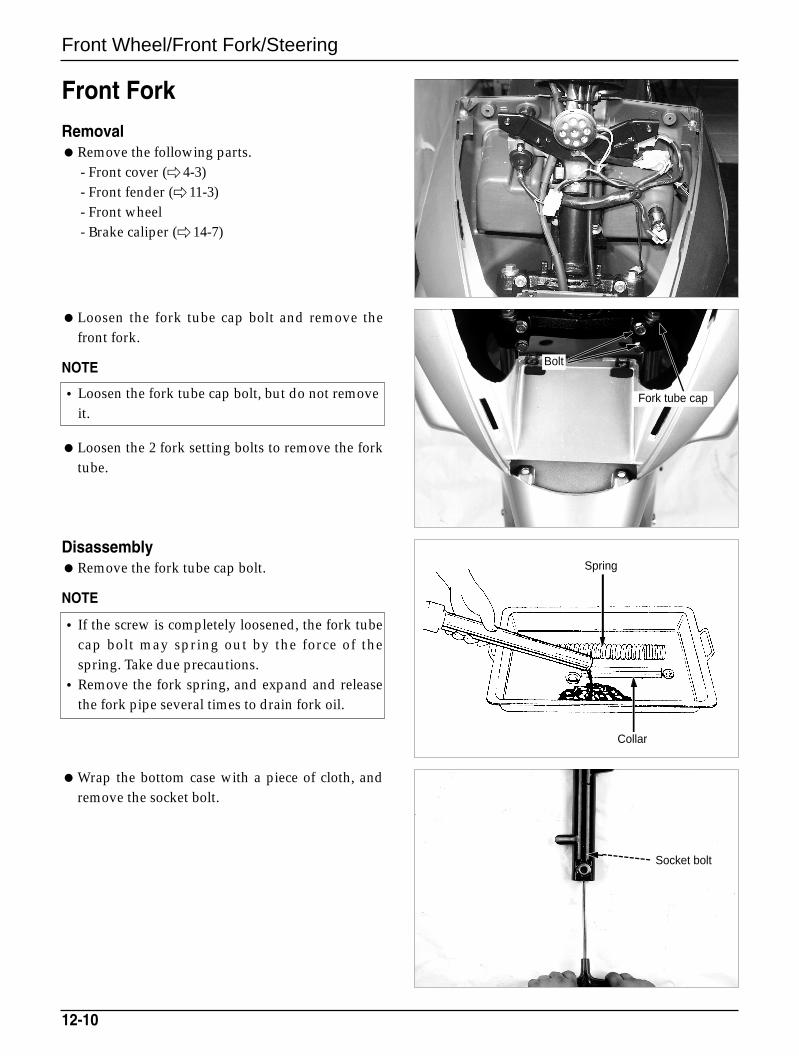
Front Wheel/Front Fork/Steering
Front Fork
RemovalRemove the following parts.
- Front cover ( 4-3)- Front fender ( 11-3)- Front wheel- Brake caliper ( 14-7)
Loosen the fork tube cap bolt and remove thefront fork.
NOTE
Loosen the 2 fork setting bolts to remove the forktube.
DisassemblyRemove the fork tube cap bolt.
NOTE
Wrap the bottom case with a piece of cloth, andremove the socket bolt.
12-10
•Loosen the fork tube cap bolt, but do not removeit.
• If the screw is completely loosened, the fork tubecap bolt may spring out by the force of thespring. Take due precautions.
•Remove the fork spring, and expand and releasethe fork pipe several times to drain fork oil.
Bolt
Fork tube cap
Spring
Collar
Socket bolt
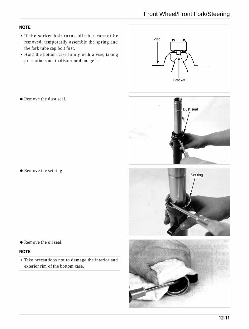
Front Wheel/Front Fork/Steering
NOTE
Remove the dust seal.
Remove the set ring.
Remove the oil seal.
NOTE
12-11
• If the socket bolt turns idle but cannot beremoved, temporarily assemble the spring andthe fork tube cap bolt first.
•Hold the bottom case firmly with a vise, takingprecautions not to distort or damage it.
•Take precautions not to damage the interior andexterior rim of the bottom case.
Dust seal
Bracket
Vise
Set ring
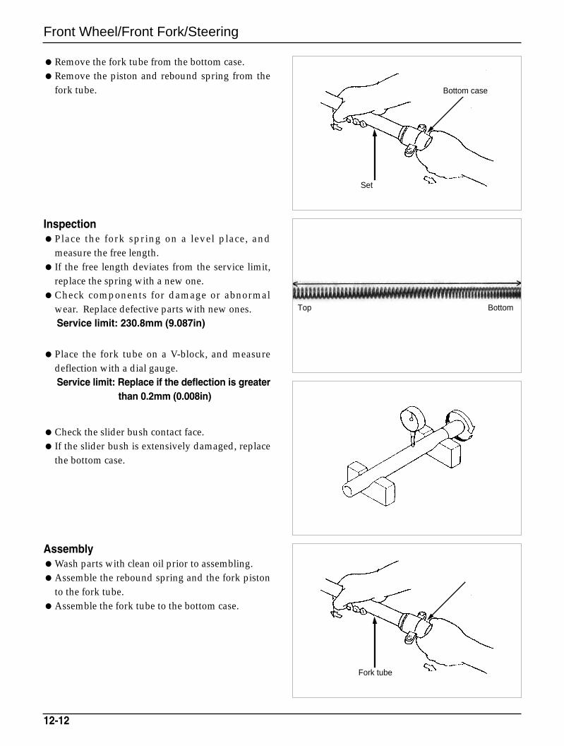
Front Wheel/Front Fork/Steering
Remove the fork tube from the bottom case.Remove the piston and rebound spring from the
fork tube.
InspectionPlace the fork spring on a level place, and
measure the free length. If the free length deviates from the service limit,
replace the spring with a new one. Check components for damage or abnormal
wear. Replace defective parts with new ones.Service limit: 230.8mm (9.087in)
Place the fork tube on a V-block, and measuredeflection with a dial gauge.Service limit: Replace if the deflection is greater
than 0.2mm (0.008in)
Check the slider bush contact face. If the slider bush is extensively damaged, replace
the bottom case.
AssemblyWash parts with clean oil prior to assembling. Assemble the rebound spring and the fork piston
to the fork tube.Assemble the fork tube to the bottom case.
12-12
Set
Top Bottom
Bottom case
Bottom case
Fork tube
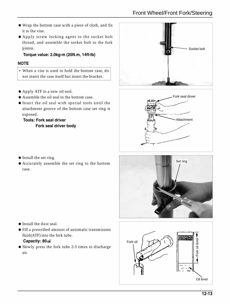
Front Wheel/Front Fork/Steering
Wrap the bottom case with a piece of cloth, and fixit to the vise.
Apply screw locking agent to the socket boltthread, and assemble the socket bolt to the forkpiston.
Torque value: 2.0kg-m (20N.m, 14ft-lb)
NOTE
Apply ATF to a new oil seal.Assemble the oil seal to the bottom case. Insert the oil seal with special tools until the
attachment groove of the bottom case set ring isexposed.Tools: Fork seal driver
Fork seal driver body
Install the set ring. Accurately assemble the set ring to the bottom
case.
Install the dust seal.Fill a prescribed amount of automatic transmission
fluid(ATF) into the fork tube.Capacity: 80
Slowly press the fork tube 2-3 times to dischargeair.
12-13
•When a vise is used to hold the bottom case, donot insert the case itself but insert the bracket.
Set ring
Attachment
Fork oil
For
k oi
l lev
el
Oil level
Fork seal driver
Socket bolt
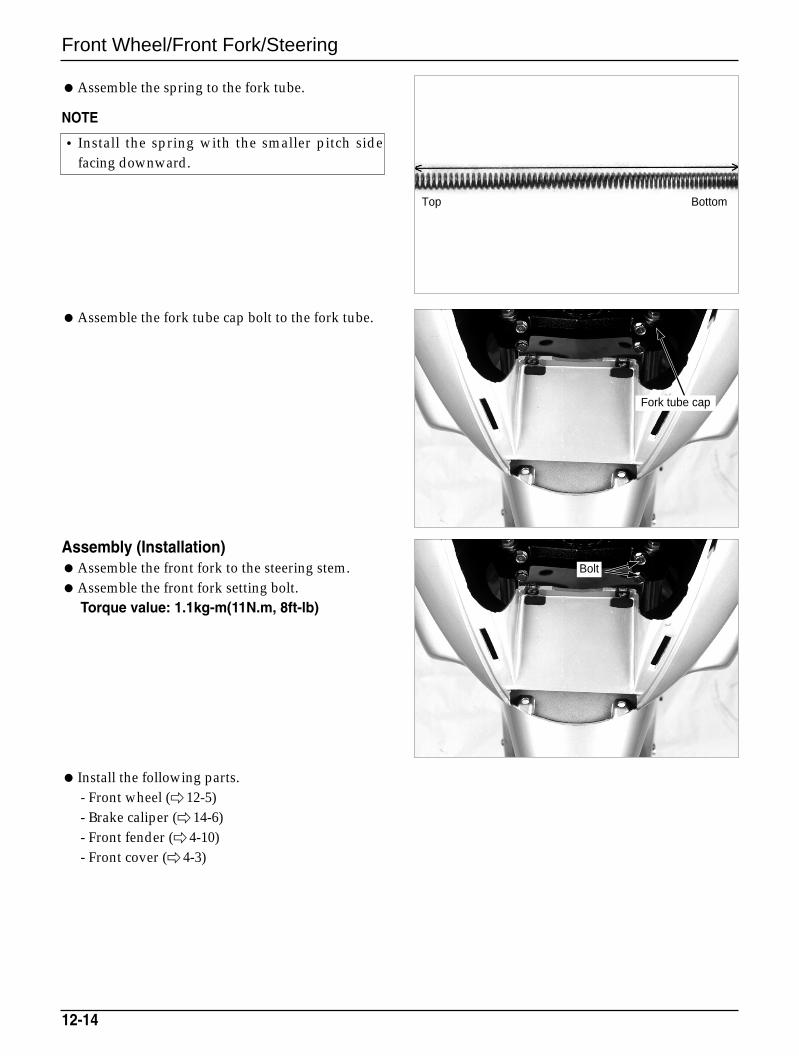
Front Wheel/Front Fork/Steering
Assemble the spring to the fork tube.
NOTE
Assemble the fork tube cap bolt to the fork tube.
Assembly (Installation)Assemble the front fork to the steering stem.Assemble the front fork setting bolt.
Torque value: 1.1kg-m(11N.m, 8ft-lb)
Install the following parts.- Front wheel ( 12-5)- Brake caliper ( 14-6)- Front fender ( 4-10)- Front cover ( 4-3)
12-14
• Install the spring with the smaller pitch sidefacing downward.
Fork tube cap
Bolt
Top Bottom
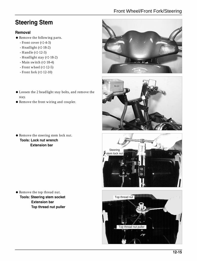
Front Wheel/Front Fork/Steering
Steering Stem
RemovalRemove the following parts.
- Front cover ( 4-3)- Headlight (18-2)- Handle ( 12-3)- Headlight stay ( 18-2)- Main switch ( 18-4)- Front wheel ( 12-5)- Front fork ( 12-10)
Loosen the 2 headlight stay bolts, and remove thestay.
Remove the front wiring and coupler.
Remove the steering stem lock nut.Tools: Lock nut wrench
Extension bar
Remove the top thread nut.Tools: Steering stem socket
Extension barTop thread nut puller
12-15
Steering stem lock nut
Top thread nut puller
Top thread nut
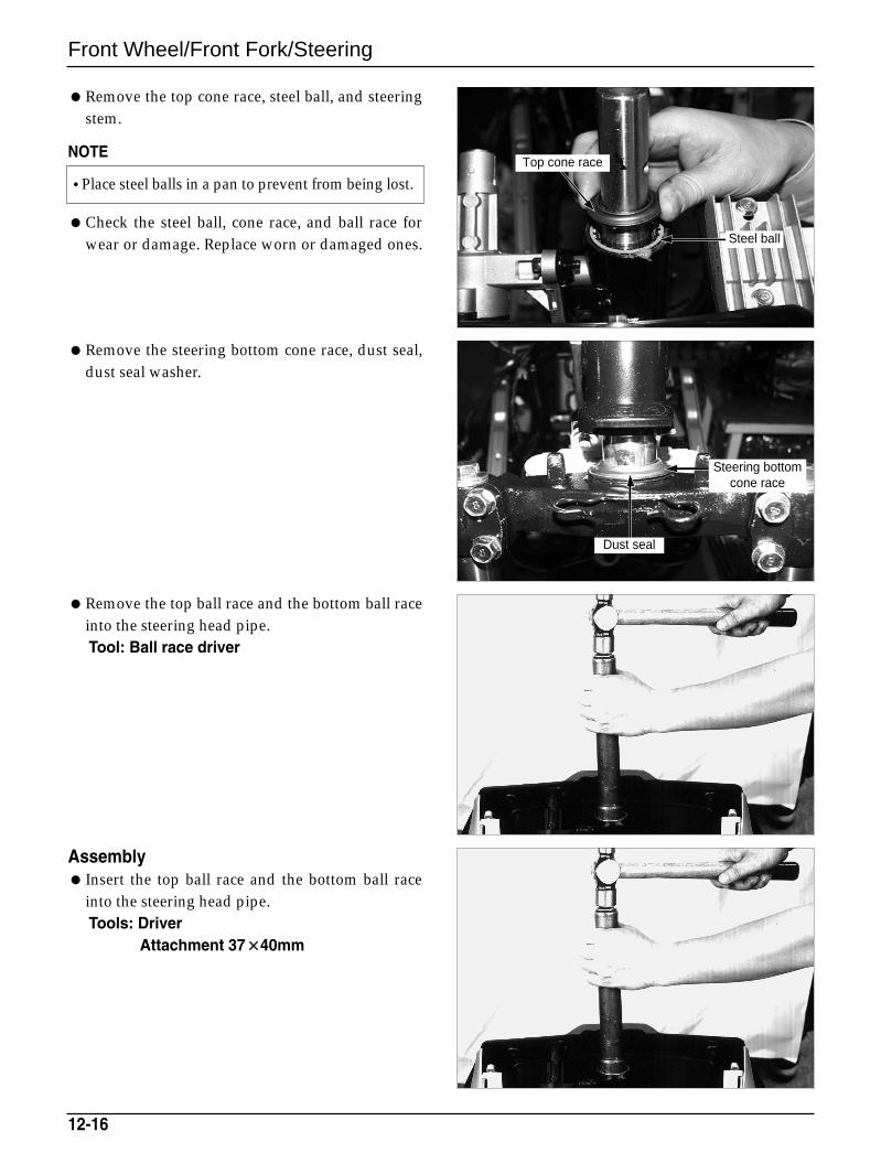
Front Wheel/Front Fork/Steering
Remove the top cone race, steel ball, and steeringstem.
NOTE
Check the steel ball, cone race, and ball race forwear or damage. Replace worn or damaged ones.
Remove the steering bottom cone race, dust seal,dust seal washer.
Remove the top ball race and the bottom ball raceinto the steering head pipe.Tool: Ball race driver
Assembly Insert the top ball race and the bottom ball race
into the steering head pipe.Tools: Driver
Attachment 37××40mm
12-16
•Place steel balls in a pan to prevent from being lost.Top cone race
Steel ball
Steering bottomcone race
Dust seal
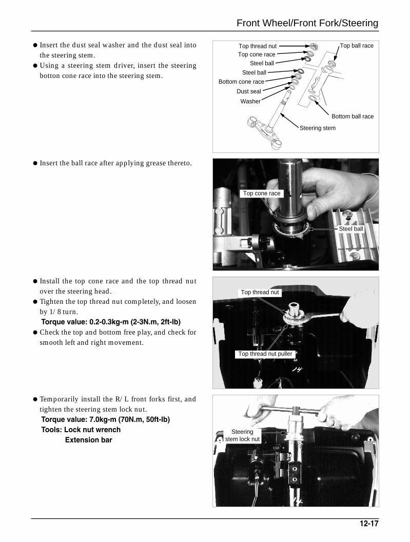
Top cone race
Top thread nutTop cone race
Steel ball
Steel ball
Bottom cone race
Dust seal
Washer
Steering stem
Steel ball
Front Wheel/Front Fork/Steering
Insert the dust seal washer and the dust seal intothe steering stem.
Using a steering stem driver, insert the steeringbotton cone race into the steering stem.
Insert the ball race after applying grease thereto.
Install the top cone race and the top thread nutover the steering head.
Tighten the top thread nut completely, and loosenby 1/8 turn.Torque value: 0.2-0.3kg-m (2-3N.m, 2ft-lb)
Check the top and bottom free play, and check forsmooth left and right movement.
Temporarily install the R/L front forks first, andtighten the steering stem lock nut.Torque value: 7.0kg-m (70N.m, 50ft-lb) Tools: Lock nut wrench
Extension bar
12-17
Steering stem lock nut
Top thread nut puller
Top thread nut
Top ball race
Bottom ball race
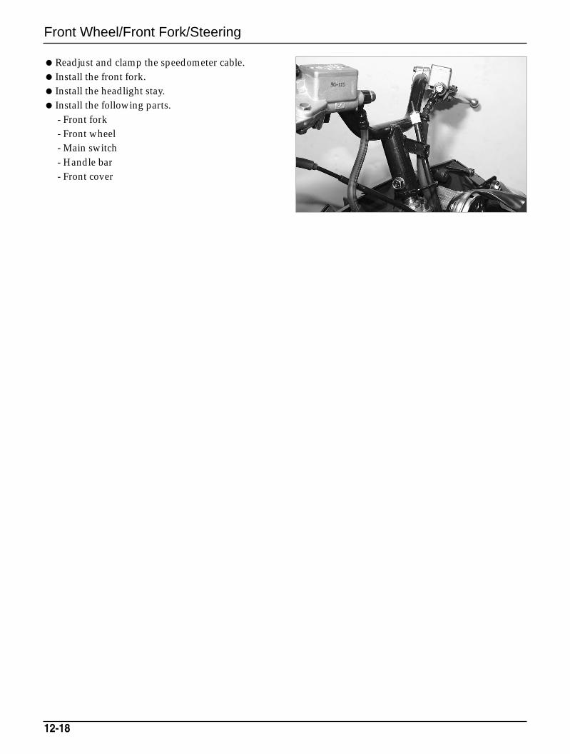
Front Wheel/Front Fork/Steering
Readjust and clamp the speedometer cable. Install the front fork. Install the headlight stay. Install the following parts.
- Front fork- Front wheel- Main switch- Handle bar- Front cover
12-18
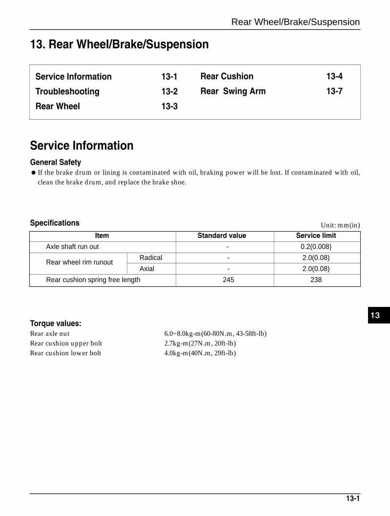
Rear Wheel/Brake/Suspension
13. Rear Wheel/Brake/Suspension
13-1
Service Information 13-1
Troubleshooting 13-2
Rear Wheel 13-3
Service InformationGeneral Safety If the brake drum or lining is contaminated with oil, braking power will be lost. If contaminated with oil,
clean the brake drum, and replace the brake shoe.
Item Standard value Service limit
Axle shaft run out - 0.2(0.008)
Rear wheel rim runoutRadical - 2.0(0.08)
Axial - 2.0(0.08)
Rear cushion spring free length 245 238
Torque values:Rear axle nut 6.0~8.0kg-m(60-80N.m, 43-58ft-lb)Rear cushion upper bolt 2.7kg-m(27N.m, 20ft-lb)Rear cushion lower bolt 4.0kg-m(40N.m, 29ft-lb)
Unit: mm(in)Specifications
13
Rear Cushion 13-4
Rear Swing Arm 13-7
Rear Wheel/Brake/Suspension
Troubleshooting
Wobble or vibration in motorcycleTire pressure incorrectFaulty tireBent rimLoose wheel bearingSwing arm bushing wornWheel out of balance
Soft suspensionWeak springsShock absorber improperly adjusted
Hard suspensionShock absorber improperly adjustedBent shock absorber rod
Suspension noiseLoose fastenersWorn shock
13-2
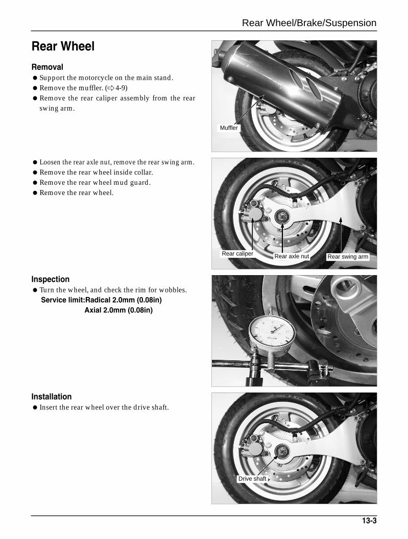
Rear Wheel/Brake/Suspension
Rear Wheel
RemovalSupport the motorcycle on the main stand.Remove the muffler. ( 4-9)Remove the rear caliper assembly from the rear
swing arm.
Loosen the rear axle nut, remove the rear swing arm. Remove the rear wheel inside collar.Remove the rear wheel mud guard.Remove the rear wheel.
InspectionTurn the wheel, and check the rim for wobbles.
Service limit:Radical 2.0mm (0.08in)Axial 2.0mm (0.08in)
Installation Insert the rear wheel over the drive shaft.
13-3
Drive shaft
Muffler
Rear caliper Rear axle nut Rear swing arm
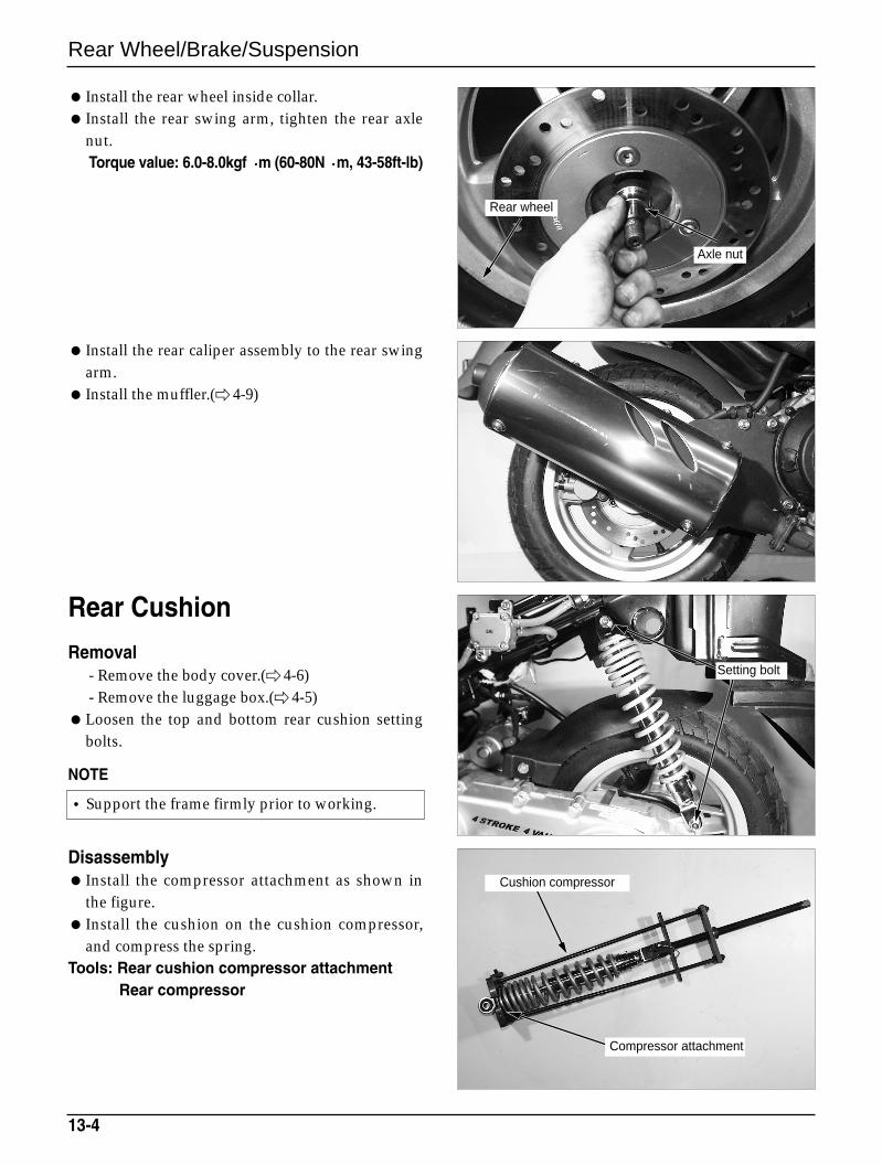
•Support the frame firmly prior to working.
Setting bolt
Cushion compressor
Compressor attachment
Rear Wheel/Brake/Suspension
Install the rear wheel inside collar. Install the rear swing arm, tighten the rear axle
nut.Torque value: 6.0-8.0kgf m (60-80N m, 43-58ft-lb)
Install the rear caliper assembly to the rear swingarm.
Install the muffler.( 4-9)
Rear Cushion
Removal- Remove the body cover.( 4-6)- Remove the luggage box.( 4-5)
Loosen the top and bottom rear cushion settingbolts.
NOTE
Disassembly Install the compressor attachment as shown in
the figure. Install the cushion on the cushion compressor,
and compress the spring.Tools: Rear cushion compressor attachment
Rear compressor
13-4
Axle nut
Rear wheel
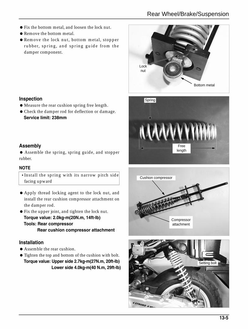
Rear Wheel/Brake/Suspension
Fix the bottom metal, and loosen the lock nut.Remove the bottom metal.Remove the lock nut, bottom metal, stopper
rubber, spring, and spring guide from thedamper component.
InspectionMeasure the rear cushion spring free length.Check the damper rod for deflection or damage.
Service limit: 238mm
Assembly Assemble the spring, spring guide, and stopperrubber.
NOTE
Apply thread locking agent to the lock nut, andinstall the rear cushion compressor attachment onthe damper rod.
Fix the upper joint, and tighten the lock nut.Torque value: 2.0kg-m(20N.m, 14ft-lb)Tools: Rear compressor
Rear cushion compressor attachment
InstallationAssemble the rear cushion.Tighten the top and bottom of the cushion with bolt.
Torque value: Upper side 2.7kg-m(27N.m, 20ft-lb)Lower side 4.0kg-m(40 N.m, 29ft-lb)
13-5
Spring
Freelength
Bottom metal
Locknut
Cushion compressor
Compressorattachment
Setting bolt
•Install the spring with its narrow pitch sidefacing upward
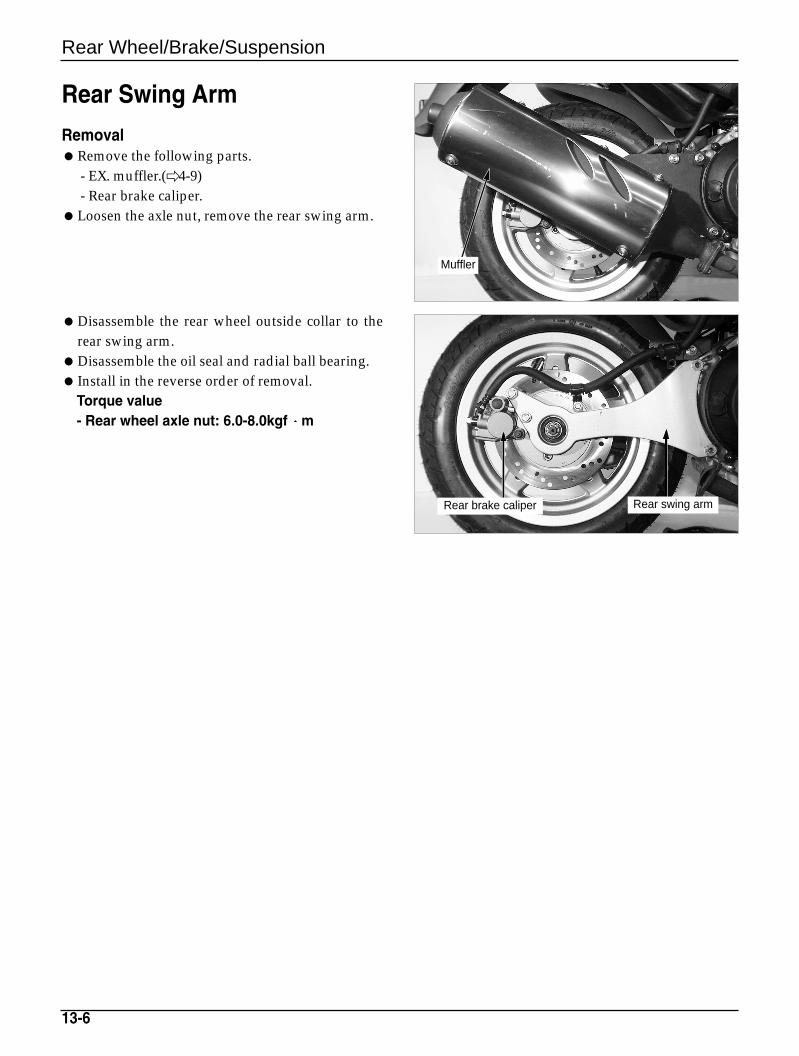
13-6
Rear Wheel/Brake/Suspension
Rear Swing Arm
RemovalRemove the following parts.
- EX. muffler.(4-9)- Rear brake caliper.
Loosen the axle nut, remove the rear swing arm.
Disassemble the rear wheel outside collar to therear swing arm.
Disassemble the oil seal and radial ball bearing. Install in the reverse order of removal.
Torque value- Rear wheel axle nut: 6.0-8.0kgf m
Muffler
Rear brake caliper Rear swing arm
Brake System
14. Brake System
14-1
Service Information 14-1
Troubleshooting 14-1
Brake Fluid/Bleeding 14-2
Brake Pad 14-3
Brake Disk 14-6
Brake Caliper 14-6
Master Cylinder 14-9
Service InformationGeneral SafetyDo not allow foreign material to enter the system when replenishing brake fluid.To prevent chemical changes, do not mix different types of brake fluid.Do not use the old brake fluid again.Brake fluid can cause damage to painted, plastic, and rubber surfaces. Take precautions not to allow parts
to be contaminated by the brake fluid.Do not reuse sealing washers.Clean the disassembled parts with brake fluid, and check for any clogged passage with compressed air.Bleed the brake hose after removing it.
TroubleshootingBraking power unsatisfactoryAir in the brake systemMoisture in brake fluidBrake pad and disk contaminatedCaliper piston seal wornMaster cylinder piston seal wornBrake pad wornCaliper inside contaminatedUnsatisfactory caliper sliding part operationLopsided wear of brake pad and diskLow brake fluid levelClogged brake fluid lineDisk bent or distortedCaliper piston seized or wornMaster cylinder piston seized or wornDisk wornMaster cylinder inside contaminatedBrake lever bent
Hard brake lever movement or unsatisfactory returnBrake system cloggedCaliper piston seized or wornUnsatisfactory caliper sliding part operationBrake fluid line cloggedCaliper piston seal wornMaster cylinder piston seized or wornBrake lever bent
Brake dragBrake pad and disk contaminated Improper wheel alignmentLopsided wear of brake pad and diskDisk bent or distortedUnsatisfactory caliper sliding part operationHydraulic system contaminated with dust.
14
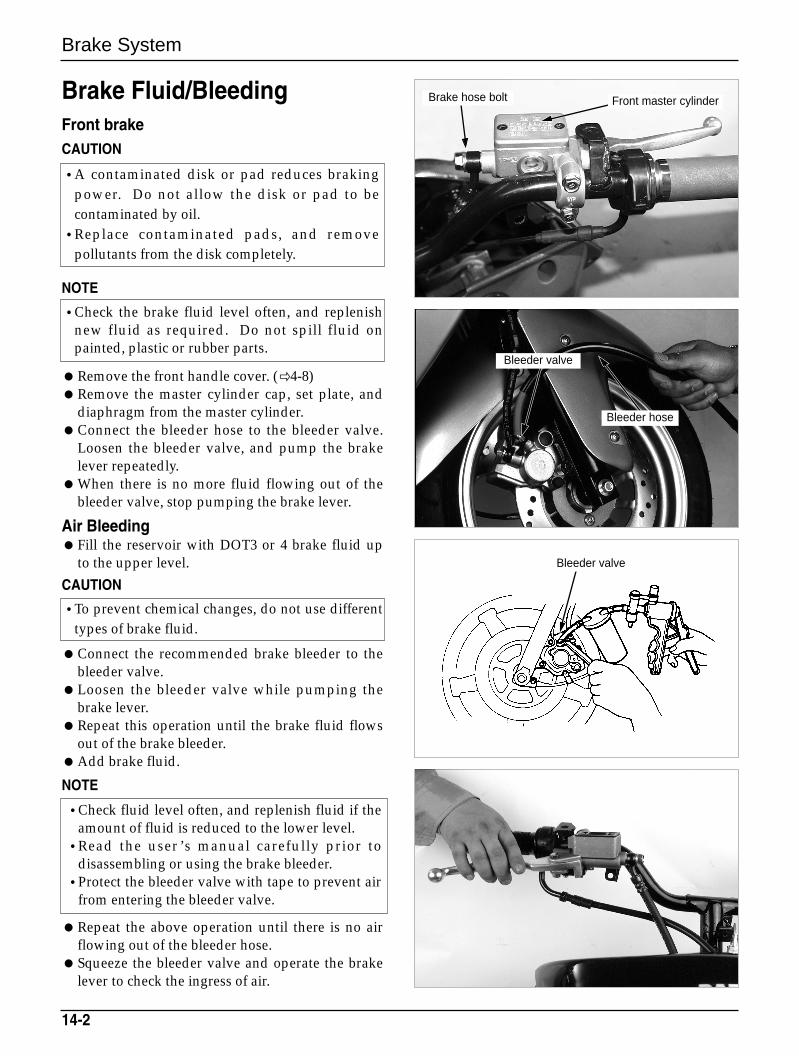
Brake System
Brake Fluid/BleedingFront brakeCAUTION
NOTE
Remove the front handle cover. (4-8)Remove the master cylinder cap, set plate, and
diaphragm from the master cylinder.Connect the bleeder hose to the bleeder valve.
Loosen the bleeder valve, and pump the brakelever repeatedly.
When there is no more fluid flowing out of thebleeder valve, stop pumping the brake lever.
Air BleedingFill the reservoir with DOT3 or 4 brake fluid up
to the upper level.
CAUTION
Connect the recommended brake bleeder to thebleeder valve.
Loosen the bleeder valve while pumping thebrake lever.
Repeat this operation until the brake fluid flowsout of the brake bleeder.
Add brake fluid.
NOTE
Repeat the above operation until there is no airflowing out of the bleeder hose.
Squeeze the bleeder valve and operate the brakelever to check the ingress of air.
14-2
•A contaminated disk or pad reduces brakingpower. Do not allow the disk or pad to becontaminated by oil.
•Replace contaminated pads, and removepollutants from the disk completely.
•Check the brake fluid level often, and replenishnew fluid as required. Do not spill fluid onpainted, plastic or rubber parts.
•To prevent chemical changes, do not use differenttypes of brake fluid.
•Check fluid level often, and replenish fluid if theamount of fluid is reduced to the lower level.
•Read the user ’s manual carefully prior todisassembling or using the brake bleeder.
•Protect the bleeder valve with tape to prevent airfrom entering the bleeder valve.
Front master cylinderBrake hose bolt
Bleeder hose
Bleeder valve
Bleeder valve
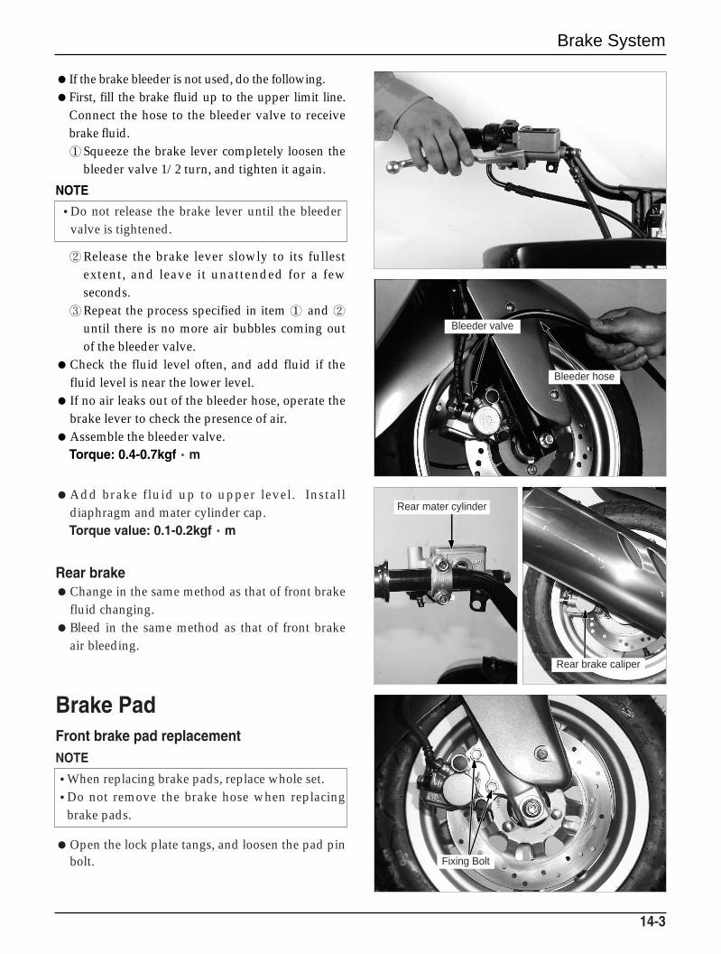
Brake System
If the brake bleeder is not used, do the following.First, fill the brake fluid up to the upper limit line.
Connect the hose to the bleeder valve to receivebrake fluid.①Squeeze the brake lever completely loosen the
bleeder valve 1/2 turn, and tighten it again.
NOTE
②Release the brake lever slowly to its fullestextent, and leave it unattended for a fewseconds.
③Repeat the process specified in item ① and ②until there is no more air bubbles coming outof the bleeder valve.
Check the fluid level often, and add fluid if thefluid level is near the lower level.
If no air leaks out of the bleeder hose, operate thebrake lever to check the presence of air.
Assemble the bleeder valve.Torque: 0.4-0.7kgf··m
Add brake fluid up to upper level. Installdiaphragm and mater cylinder cap.Torque value: 0.1-0.2kgf··m
Rear brakeChange in the same method as that of front brake
fluid changing.Bleed in the same method as that of front brake
air bleeding.
Brake PadFront brake pad replacementNOTE
Open the lock plate tangs, and loosen the pad pinbolt.
14-3
•Do not release the brake lever until the bleedervalve is tightened.
Bleeder hose
Bleeder valve
Rear mater cylinder
Rear brake caliper
Fixing Bolt
•When replacing brake pads, replace whole set.•Do not remove the brake hose when replacing
brake pads.
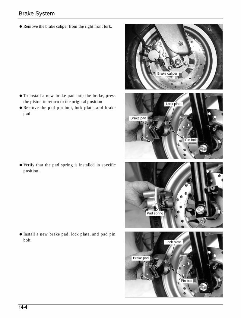
Brake System
Remove the brake caliper from the right front fork.
To install a new brake pad into the brake, pressthe piston to return to the original position.
Remove the pad pin bolt, lock plate, and brakepad.
Verify that the pad spring is installed in specificposition.
Install a new brake pad, lock plate, and pad pinbolt.
14-4
Brake caliper
Lock plate
Pin bolt
Brake pad
Lock plate
Pin bolt
Brake pad
Pad spring
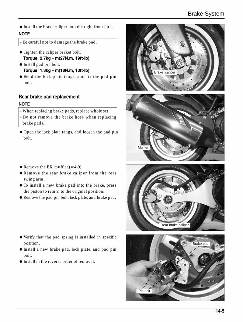
Brake System
Install the brake caliper into the right front fork.
NOTE
Tighten the caliper braket bolt.Torque: 2.7kg––m(27N.m, 19ft-lb)
Install pad pin bolt.Torque: 1.8kg––m(18N.m, 13ft-lb)
Bend the lock plate tangs, and fix the pad pinbolt.
Rear brake pad replacementNOTE
Open the lock plate tangs, and loosen the pad pinbolt.
Remove the EX. muffler.(4-9)Remove the rear brake caliper from the rear
swing arm.To install a new brake pad into the brake, press
the piston to return to the original position.Remove the pad pin bolt, lock plate, and brake pad.
Verify that the pad spring is installed in specificposition.
Install a new brake pad, lock plate, and pad pinbolt.
Install in the reverse order of removal.
14-5
•Be careful not to damage the brake pad.
•When replacing brake pads, replace whole set.•Do not remove the brake hose when replacing
brake pads.
Brake caliper
Muffler
Pin bolt
Brake pad
Rear brake caliper
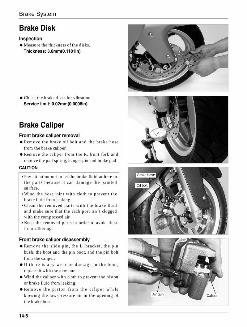
Brake System
Brake DiskInspectionMeasure the thickness of the disks.
Thickness: 3.0mm(0.1181in)
Check the brake disks for vibration.Service limit: 0.02mm(0.0008in)
Brake CaliperFront brake caliper removalRemove the brake oil bolt and the brake hose
from the brake caliper.Remove the caliper from the R. front fork and
remove the pad spring, hanger pin and brake pad.
CAUTION
Front brake caliper disassemblyRemove the slide pin, the L. bracket, the pin
bush, the boot and the pin boot, and the pin boltfrom the caliper.
If there is any wear or damage in the boot,replace it with the new one.
Wind the caliper with cloth to prevent the pistonor brake fluid from leaking.
Remove the piston from the caliper whileblowing the low-pressure air in the opening ofthe brake hose.
14-6
•Pay attention not to let the brake fluid adhere tothe parts because it can damage the paintedsurface.
•Wind the hose joint with cloth to prevent thebrake fluid from leaking.
•Clean the removed parts with the brake fluidand make sure that the each port isn t cloggedwith the compressed air.
•Keep the removed parts in order to avoid dustfrom adhering.
Brake hose
Oil bolt
Air gun Caliper
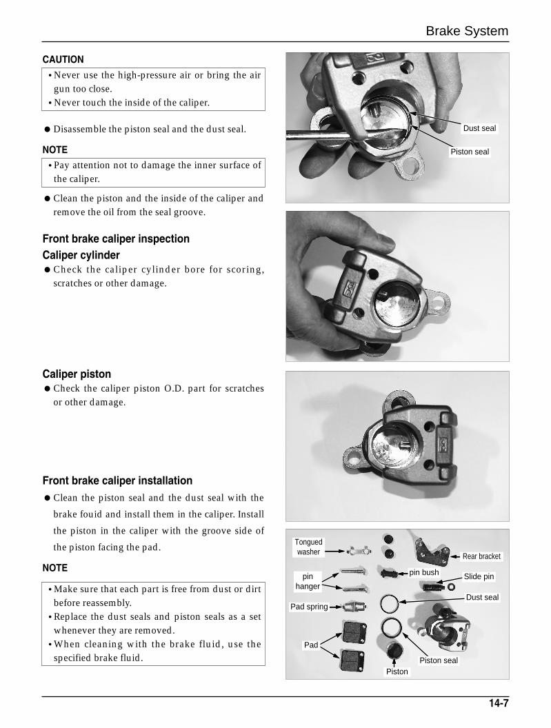
Brake System
CAUTION
Disassemble the piston seal and the dust seal.
NOTE
Clean the piston and the inside of the caliper andremove the oil from the seal groove.
Front brake caliper inspectionCaliper cylinderCheck the caliper cylinder bore for scoring,
scratches or other damage.
Caliper pistonCheck the caliper piston O.D. part for scratches
or other damage.
Front brake caliper installationClean the piston seal and the dust seal with the
brake fouid and install them in the caliper. Install
the piston in the caliper with the groove side of
the piston facing the pad.
NOTE
14-7
•Make sure that each part is free from dust or dirtbefore reassembly.
•Replace the dust seals and piston seals as a setwhenever they are removed.
•When cleaning with the brake fluid, use thespecified brake fluid.
•Never use the high-pressure air or bring the airgun too close.
•Never touch the inside of the caliper.
•Pay attention not to damage the inner surface ofthe caliper.
Dust seal
Piston seal
Rear bracket
Slide pinpin bush
Dust seal
Piston sealPiston
Tonguedwasher
pinhanger
Pad spring
Pad
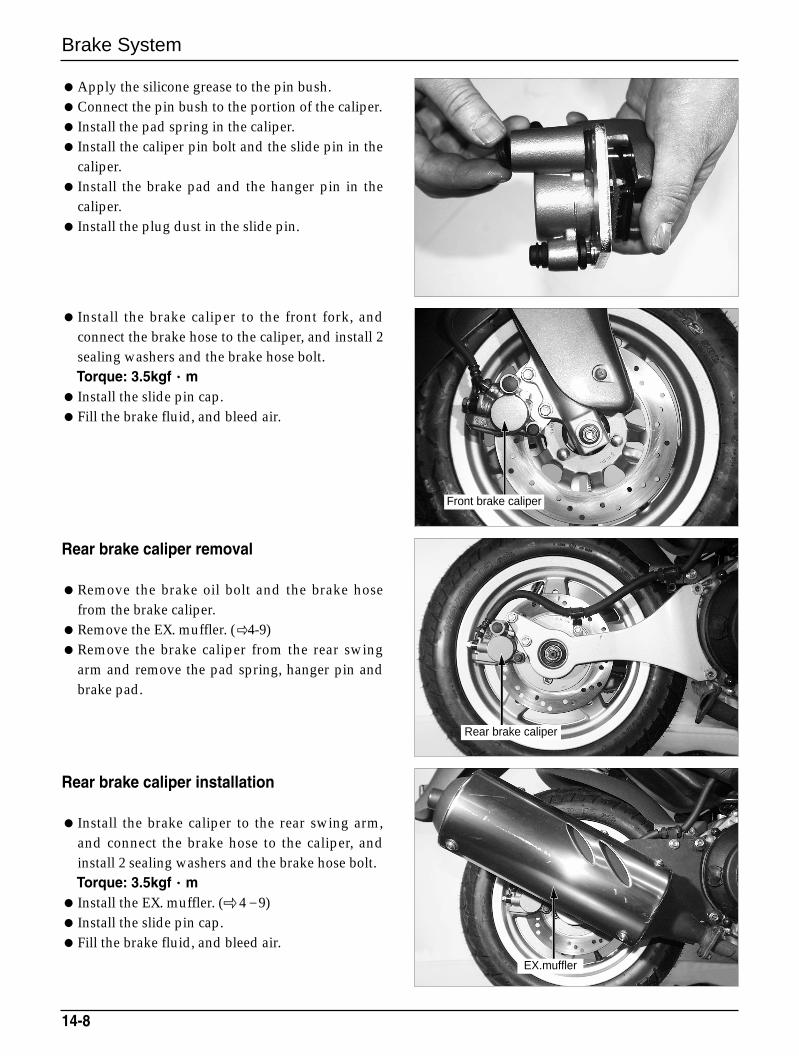
Brake System
14-8
Apply the silicone grease to the pin bush.Connect the pin bush to the portion of the caliper. Install the pad spring in the caliper. Install the caliper pin bolt and the slide pin in the
caliper. Install the brake pad and the hanger pin in the
caliper. Install the plug dust in the slide pin.
Install the brake caliper to the front fork, andconnect the brake hose to the caliper, and install 2sealing washers and the brake hose bolt.Torque: 3.5kgf··m
Install the slide pin cap.Fill the brake fluid, and bleed air.
Rear brake caliper removal
Remove the brake oil bolt and the brake hosefrom the brake caliper.
Remove the EX. muffler. (4-9)Remove the brake caliper from the rear swing
arm and remove the pad spring, hanger pin andbrake pad.
Rear brake caliper installation
Install the brake caliper to the rear swing arm,and connect the brake hose to the caliper, andinstall 2 sealing washers and the brake hose bolt. Torque: 3.5kgf··m
Install the EX. muffler. ( 4–9) Install the slide pin cap.Fill the brake fluid, and bleed air.
Front brake caliper
Rear brake caliper
EX.muffler
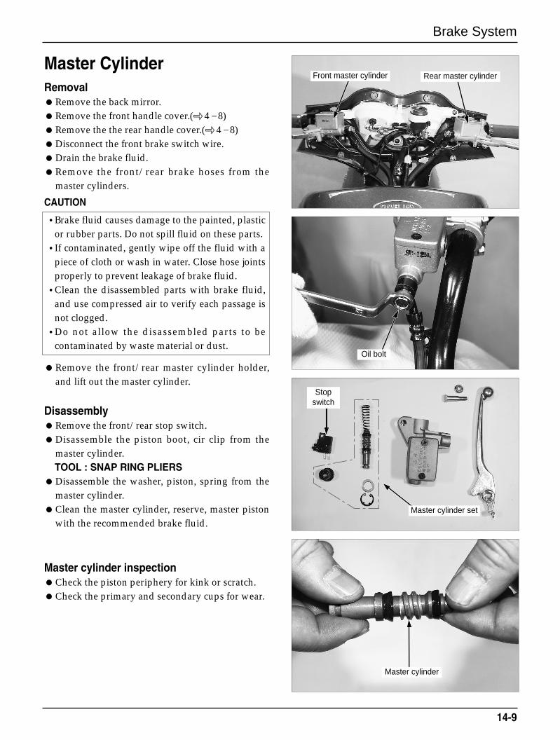
Brake System
14-9
Master CylinderRemovalRemove the back mirror.Remove the front handle cover.(4–8)Remove the the rear handle cover.( 4–8)Disconnect the front brake switch wire.Drain the brake fluid.Remove the front/rear brake hoses from the
master cylinders.
CAUTION
Remove the front/rear master cylinder holder,and lift out the master cylinder.
DisassemblyRemove the front/rear stop switch.Disassemble the piston boot, cir clip from the
master cylinder.TOOL : SNAP RING PLIERS
Disassemble the washer, piston, spring from themaster cylinder.
Clean the master cylinder, reserve, master pistonwith the recommended brake fluid.
Master cylinder inspectionCheck the piston periphery for kink or scratch.Check the primary and secondary cups for wear.
•Brake fluid causes damage to the painted, plasticor rubber parts. Do not spill fluid on these parts.
•If contaminated, gently wipe off the fluid with apiece of cloth or wash in water. Close hose jointsproperly to prevent leakage of brake fluid.
•Clean the disassembled parts with brake fluid,and use compressed air to verify each passage isnot clogged.
•Do not allow the disassembled parts to becontaminated by waste material or dust.
Front master cylinder
Oil bolt
Stopswitch
Master cylinder set
Master cylinder
Rear master cylinder
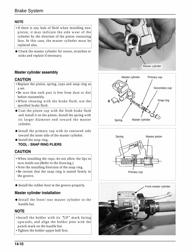
Brake System
14-10
NOTE
Chack the master cylinder for scores, scratches ornicks and replace if necessary.
Master cylinder assembly
CAUTION
Coat the piston cup with the fresh brake fluidand install it on the piston. Install the spring withits larger diameter end toward the mastercylinder.
Install the primary cup with its concaved sidetoward the inner side of the master cylinder.
Install the snap ring.TOOL : SNAP RING PLIERS
CAUTION
Install the rubber boot in the groove properly.
Master cylinder installation
Install the front/rear master cylinder to thehandle bar.
NOTE
•If there is any leak of fluid when installing newpiston, it may indicate the side wear of thecylinder by the direction of the piston contactingface. In this case, the master cylinder must bereplaced also.
•Replace the piston, spring, cups and snap ring asa set.
•Be sure that each part is free from dust or dirtbefore reassembly.
•When cleaning with the brake fluid, use thespecified brake fluid.
•When installing the cups, do not allow the lips toturn inside out.(Refer to the drawing.)
•Note the installing direction of the snap ring.•Be certain that the snap ring is seated firmly in
the groove.
•Install the holder with its UP mark facingupwards, and align the holder joint with thepunch mark on the handle bar.
•Tighten the holder upper bolt first.
Front master cylinder
Master cylinder
Master cylinder Primary cup
Secondary cup
Snap ring
Master cylinderSpring
Spring Master piston
Primary cup
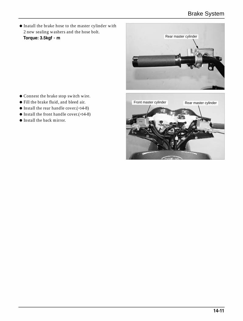
Brake System
14-11
Inatall the brake hose to the master cylinder with2 new sealing washers and the hose bolt.Torque: 3.5kgf··m
Connest the brake stop switch wire.Fill the brake fluid, and bleed air. Install the rear handle cover.(4-8) Install the front handle cover.(4-8) Install the back mirror.
Front master cylinder Rear master cylinder
Rear master cylinder

MEMO
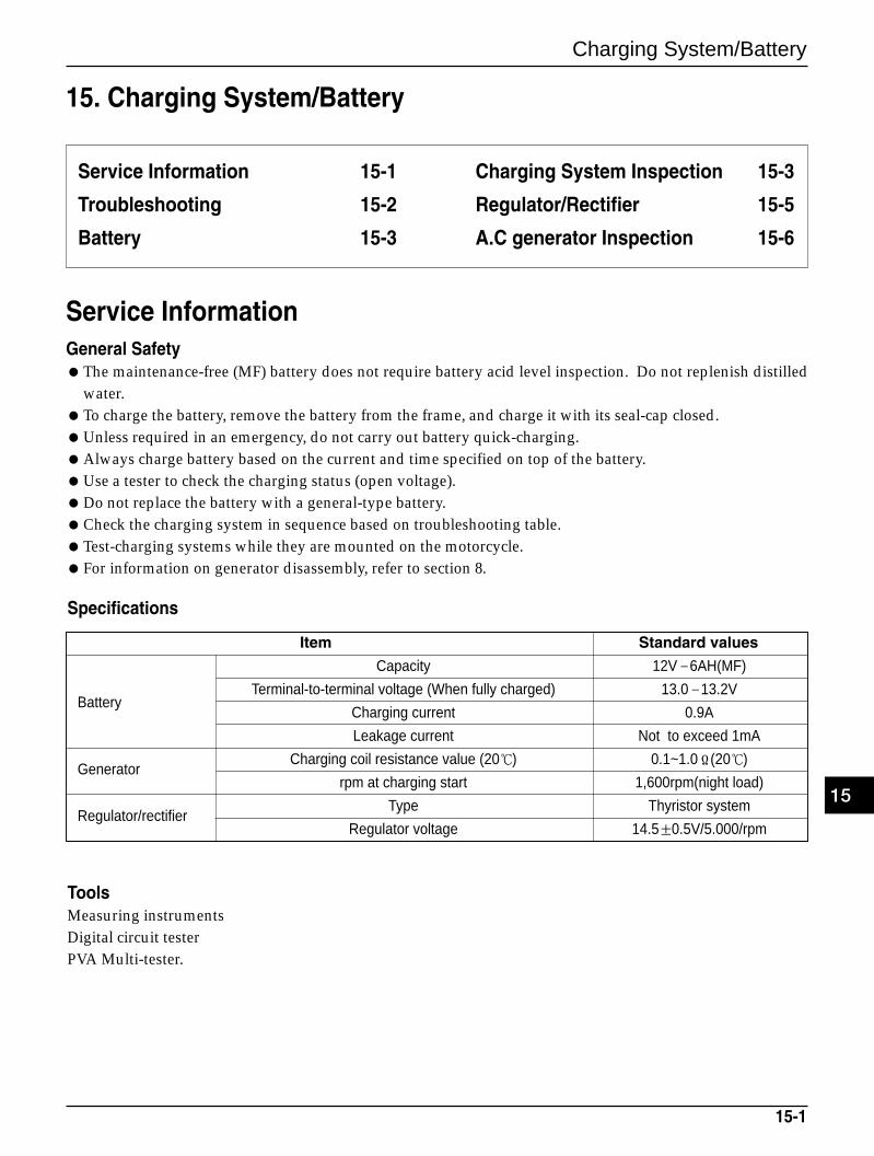
Charging System/Battery
15-1
15. Charging System/Battery
Service Information 15-1
Troubleshooting 15-2
Battery 15-3
Charging System Inspection 15-3
Regulator/Rectifier 15-5
A.C generator Inspection 15-6
Service InformationGeneral SafetyThe maintenance-free (MF) battery does not require battery acid level inspection. Do not replenish distilled
water.To charge the battery, remove the battery from the frame, and charge it with its seal-cap closed.Unless required in an emergency, do not carry out battery quick-charging.Always charge battery based on the current and time specified on top of the battery.Use a tester to check the charging status (open voltage).Do not replace the battery with a general-type battery.Check the charging system in sequence based on troubleshooting table.Test-charging systems while they are mounted on the motorcycle.For information on generator disassembly, refer to section 8.
Item Standard values
Capacity 12V–6AH(MF)
Terminal-to-terminal voltage (When fully charged) 13.0–13.2VBattery
Charging current 0.9A
Leakage current Not to exceed 1mA
GeneratorCharging coil resistance value (20) 0.1~1.0Ω(20)
rpm at charging start 1,600rpm(night load)
Regulator/rectifierType Thyristor system
Regulator voltage 14.5±0.5V/5.000/rpm
ToolsMeasuring instrumentsDigital circuit testerPVA Multi-tester.
Specifications
15
Charging System/Battery
TroubleshootingNo power - key turned onDead battery
- Low fluid level- Low specific gravity- Charging system failure
Disconnected battery cableMain fuse burned out Faulty ignition switch
Low voltage - key turned onWeak battery
- Low fluid level- Low specific gravity- Charging system failure
Loose battery connection
Low power - engine runningBattery undercharged
-Low fluid level- One or more dead cells
Charging system failure
Intermittent powerLoose battery connectionLoose charging system connectionLoose starting system connectionLoose connection or short circuit in ignition system
Charging System FailureLoose, broken or shorted wire or connectionFaulty voltage regulatorFaulty rectifierFaulty alternator
15-2
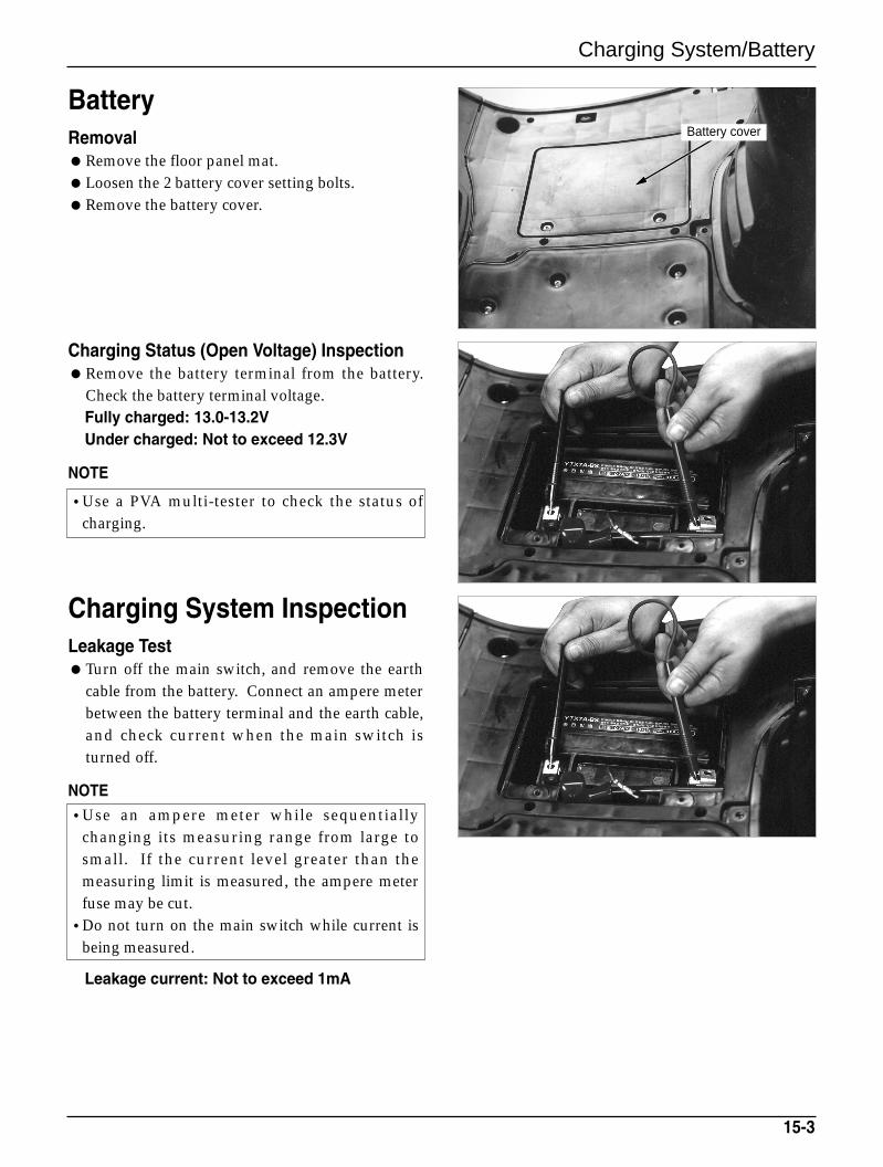
Charging System/Battery
BatteryRemovalRemove the floor panel mat.Loosen the 2 battery cover setting bolts.Remove the battery cover.
Charging Status (Open Voltage) InspectionRemove the battery terminal from the battery.
Check the battery terminal voltage.Fully charged: 13.0-13.2VUnder charged: Not to exceed 12.3V
NOTE
Charging System InspectionLeakage TestTurn off the main switch, and remove the earth
cable from the battery. Connect an ampere meterbetween the battery terminal and the earth cable,and check current when the main switch isturned off.
NOTE
Leakage current: Not to exceed 1mA
15-3
•Use a PVA multi-tester to check the status ofcharging.
•Use an ampere meter while sequentiallychanging its measuring range from large tosmall. If the current level greater than themeasuring limit is measured, the ampere meterfuse may be cut.
•Do not turn on the main switch while current isbeing measured.
Battery cover
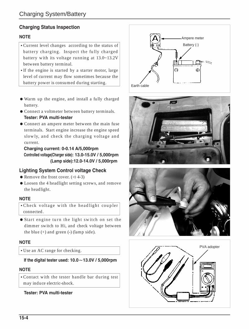
Charging System/Battery
Charging Status Inspection
NOTE
Warm up the engine, and install a fully chargedbattery.
Connect a voltmeter between battery terminals.Tester: PVA multi-tester
Connect an ampere meter between the main fuseterminals. Start engine increase the engine speedslowly, and check the charging voltage andcurrent.Charging current: 0-0.14 A/5,000rpmControlled voltage(Charger side): 13.0-15.0V / 5,000rpm
(Lamp side):12.0-14.0V / 5,000rpm
Lighting System Control voltage CheckRemove the front cover. ( 4-3)Loosen the 4 headlight setting screws, and remove
the headlight.
NOTE
Start engine turn the light switch on set thedimmer switch to Hi, and check voltage betweenthe blue (+) and green (-) (lamp side).
NOTE
If the digital tester used: 10.0〜〜13.0V / 5,000rpm
NOTE
Tester: PVA multi-tester
15-4
•Current level changes according to the status ofbattery charging. Inspect the fully chargedbattery with its voltage running at 13.0~13.2Vbetween battery terminal.
•If the engine is started by a starter motor, largelevel of current may flow sometimes because thebattery power is consumed during starting.
•Check voltage with the headlight couplerconnected.
•Use an AC range for checking.
•Contact with the tester handle bar during testmay induce electric-shock.
Ampere meter
Battery (-)
Earth cable
PVA adopter
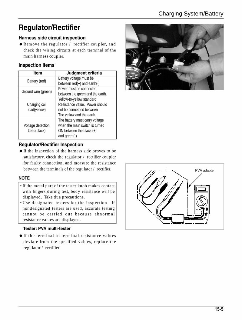
Charging System/Battery
Regulator/RectifierHarness side circuit inspectionRemove the regulator / rectifier coupler, and
check the wiring circuits at each terminal of themain harness coupler.
Inspection Items
Item Judgment criteria
Battery (red)Battery voltage must be between red(+) and earth(-)
Ground wire (green)Power must be connectedbetween the green and the earth.Yellow-to-yellow standard
Charging coil Resistance value. Power shouldlead(yellow) not be connected between
The yellow and the earth.The battery must carry voltage
Voltage detection when the main switch is turned Lead(black) ON between the black (+)
and green(-)
Regulator/Rectifier Inspection If the inspection of the harness side proves to be
satisfactory, check the regulator / rectifier couplerfor faulty connection, and measure the resistancebetween the terminals of the regulator / rectifier.
NOTE
Tester: PVA multi-tester
15-5
•If the metal part of the tester knob makes contactwith fingers during test, body resistance will bedisplayed. Take due precautions.
•Use designated testers for the inspection. Ifnondesignated testers are used, accurate testingcannot be carried out because abnormalresistance values are displayed.
If the terminal-to-terminal resistance valuesdeviate from the specified values, replace theregulator / rectifier.
PVA adapter
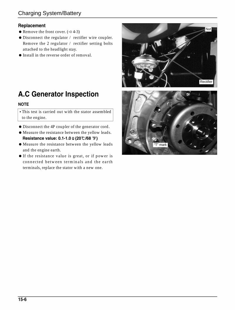
“T” mark
Charging System/Battery
ReplacementRemove the front cover. ( 4-3)Disconnect the regulator / rectifier wire coupler.
Remove the 2 regulator / rectifier setting boltsattached to the headlight stay.
Install in the reverse order of removal.
A.C Generator InspectionNOTE
Disconnect the 4P coupler of the generator cord.Measure the resistance between the yellow leads.
Resistance value: 0.1-1.0ΩΩ(20/68 )Measure the resistance between the yellow leads
and the engine earth. If the resistance value is great, or if power is
connected between terminals and the earthterminals, replace the stator with a new one.
15-6
•This test is carried out with the stator assembledto the engine.
Nut
Rectifier
Ignition System
16-1
16. Ignition system
Service Information 16-1
Troubleshooting 16-2
CDI Unit Inspection 16-3
Ignition Coil Inspection 16-4
Pulse Generator Inspection 16-5
A.C Generator Inspection 16-5
Ignition Timing Check 16-6
Side Stand Cut-off Switch 16-6
Service InformationGeneral SafetyCarry out inspection in sequence based on the troubleshooting table. If the CDI unit is dropped, or if strong shock is applied thereto, CDI unit malfunction may result. Take due
precautions when handling it. Also, if the connector or coupler is connected or disconnected when there iscurrent flowing, overvoltage may occur on the unit leading to circuit damage. Always turn off the mainswitch prior to servicing.
Ignition timing cannot be adjusted because the ignition system is of CDI type.Spark plug check. ( 3 - 5)Connect the same color cords. Pay particular attention to colors prior to removing wiring. Connect the
same color couplers.The resistance value may slightly differ from the standard values depending on each measuring situation.
Item Standard value
Primary coil 0.1~0.2ΩIgnition coil
7.3~11kΩResistance value
With plug cap
20(68)Secondary coil
Without plug cap 3.6~4.6KΩ
Pulse generator coil resistance value 20(68) 50~170ΩA.C. generator coil resistance value 20(68) 50~350Ω
Specifications
ToolsMeasuring instrumentsDigital circuit testerPVA multi-testerInspection adapterSpark adapter
16
Ignition System
Troubleshooting
No spark at plug Poorly connected, broken or shorted wires
- Between the A.C. generator and CDI unit- Between the CDI unit and ignition coil- Between the CDI unit and main switch- Between the ignition coil and plug
Faulty main switch Faulty ignition coil Faulty CDI unit Faulty A.C. generator Faulty pulse generator
Poor Engine Running Primary ignition circuit
- Faulty ignition coil- Faulty wire connection- Faulty CDI unit
Secondary ignition circuit- Faulty plug- Faulty high-tension cord- Faulty pulse generator- Faulty spark plug cord
Ignition timing- Faulty A.C. generator- Faulty CDI unit- Faulty pulse generator
16-2
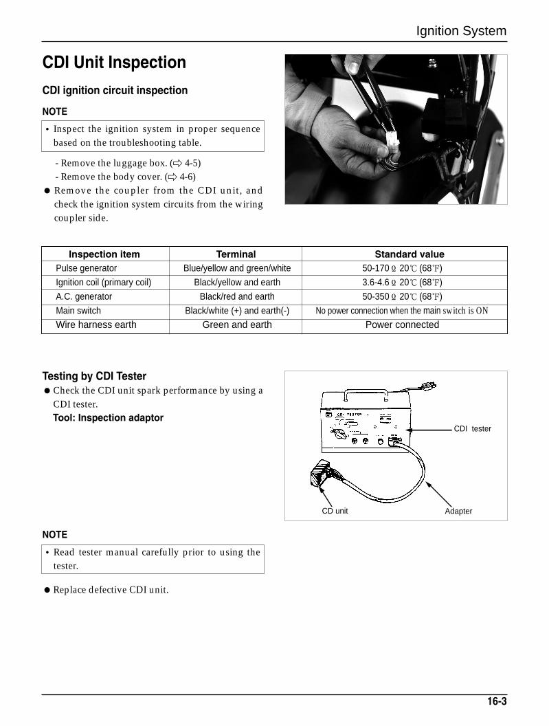
Ignition System
CDI Unit Inspection
CDI ignition circuit inspection
NOTE
- Remove the luggage box. ( 4-5)- Remove the body cover. ( 4-6)
Remove the coupler from the CDI unit, andcheck the ignition system circuits from the wiringcoupler side.
Testing by CDI TesterCheck the CDI unit spark performance by using a
CDI tester.Tool: Inspection adaptor
NOTE
Replace defective CDI unit.
16-3
Inspection item Terminal Standard valuePulse generator Blue/yellow and green/white 50-170Ω 20 (68)
Ignition coil (primary coil) Black/yellow and earth 3.6-4.6Ω 20 (68)
A.C. generator Black/red and earth 50-350Ω 20 (68)
Main switch Black/white (+) and earth(-) No power connection when the main switch is ONWire harness earth Green and earth Power connected
• Inspect the ignition system in proper sequencebased on the troubleshooting table.
•Read tester manual carefully prior to using thetester.
Adapter
CDI tester
CD unit
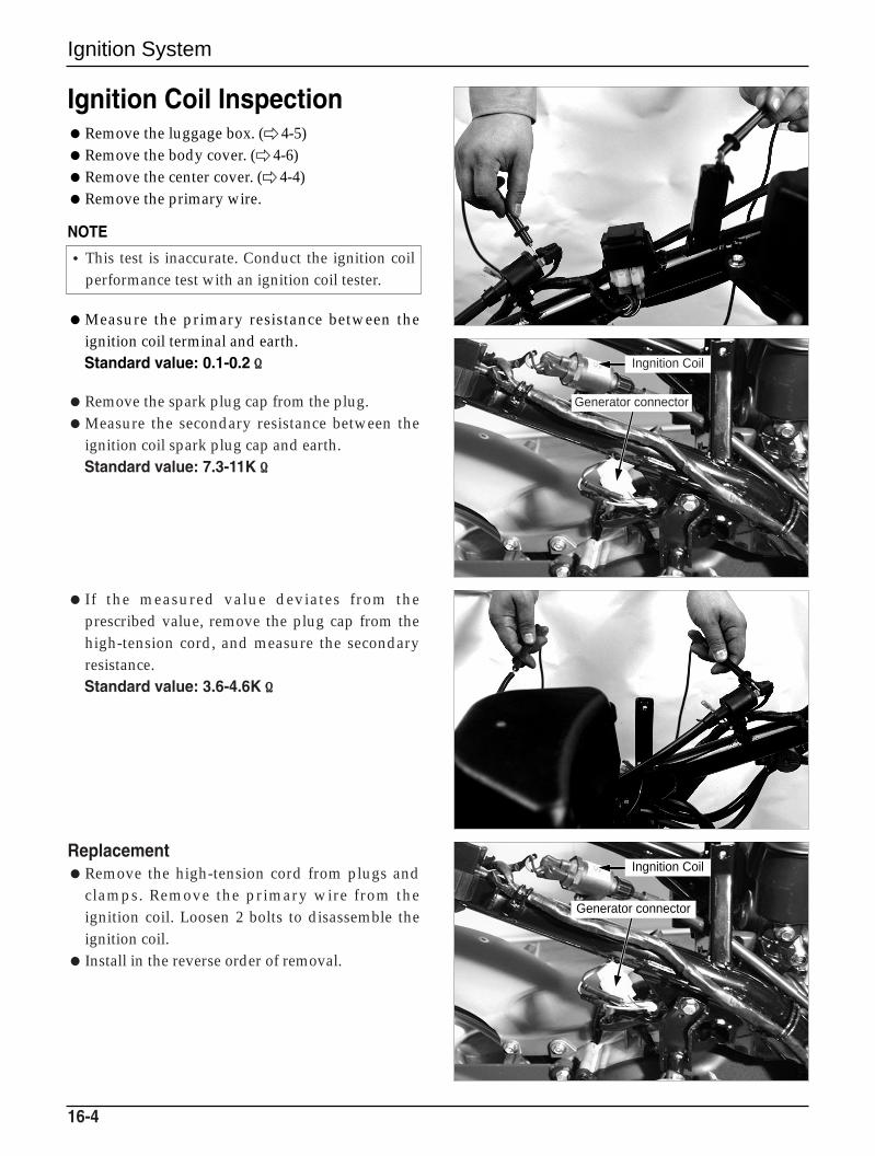
Ingnition Coil
Generator connector
Ignition System
Ignition Coil InspectionRemove the luggage box. ( 4-5)Remove the body cover. ( 4-6)Remove the center cover. ( 4-4)Remove the primary wire.
NOTE
Measure the primary resistance between theignition coil terminal and earth.Standard value: 0.1-0.2ΩΩ
Remove the spark plug cap from the plug.Measure the secondary resistance between the
ignition coil spark plug cap and earth.Standard value: 7.3-11KΩΩ
If the measured value deviates from theprescribed value, remove the plug cap from thehigh-tension cord, and measure the secondaryresistance.Standard value: 3.6-4.6KΩΩ
ReplacementRemove the high-tension cord from plugs and
clamps. Remove the primary wire from theignition coil. Loosen 2 bolts to disassemble theignition coil.
Install in the reverse order of removal.
16-4
•This test is inaccurate. Conduct the ignition coilperformance test with an ignition coil tester.
Ingnition Coil
Generator connector
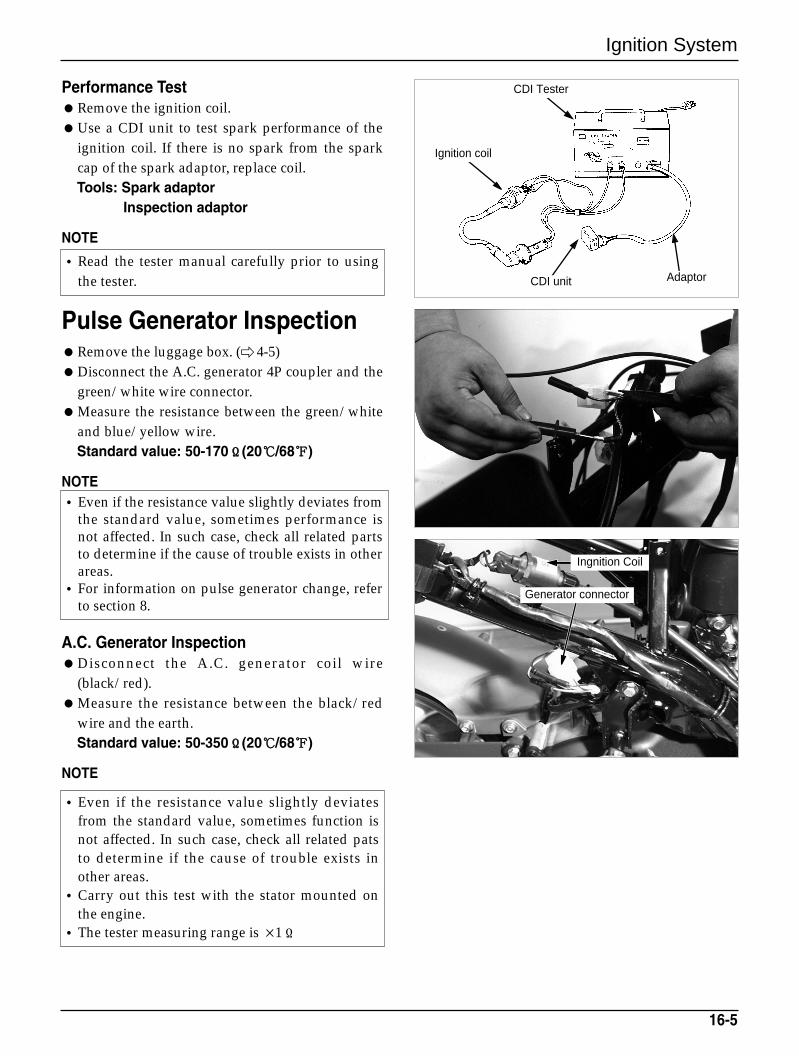
Ingnition Coil
Generator connector
Ignition System
Performance TestRemove the ignition coil.Use a CDI unit to test spark performance of the
ignition coil. If there is no spark from the sparkcap of the spark adaptor, replace coil.Tools: Spark adaptor
Inspection adaptor
NOTE
Pulse Generator InspectionRemove the luggage box. ( 4-5)Disconnect the A.C. generator 4P coupler and the
green/white wire connector.Measure the resistance between the green/white
and blue/yellow wire.Standard value: 50-170ΩΩ(20/68)
NOTE
A.C. Generator InspectionDisconnect the A.C. generator coil wire
(black/red).Measure the resistance between the black/red
wire and the earth.Standard value: 50-350ΩΩ(20/68)
NOTE
16-5
•Read the tester manual carefully prior to usingthe tester.
•Even if the resistance value slightly deviates fromthe standard value, sometimes performance isnot affected. In such case, check all related partsto determine if the cause of trouble exists in otherareas.
•For information on pulse generator change, referto section 8.
•Even if the resistance value slightly deviatesfrom the standard value, sometimes function isnot affected. In such case, check all related patsto determine if the cause of trouble exists inother areas.
•Carry out this test with the stator mounted onthe engine.
•The tester measuring range is ×1Ω
CDI unit Adaptor
CDI Tester
Ignition coil
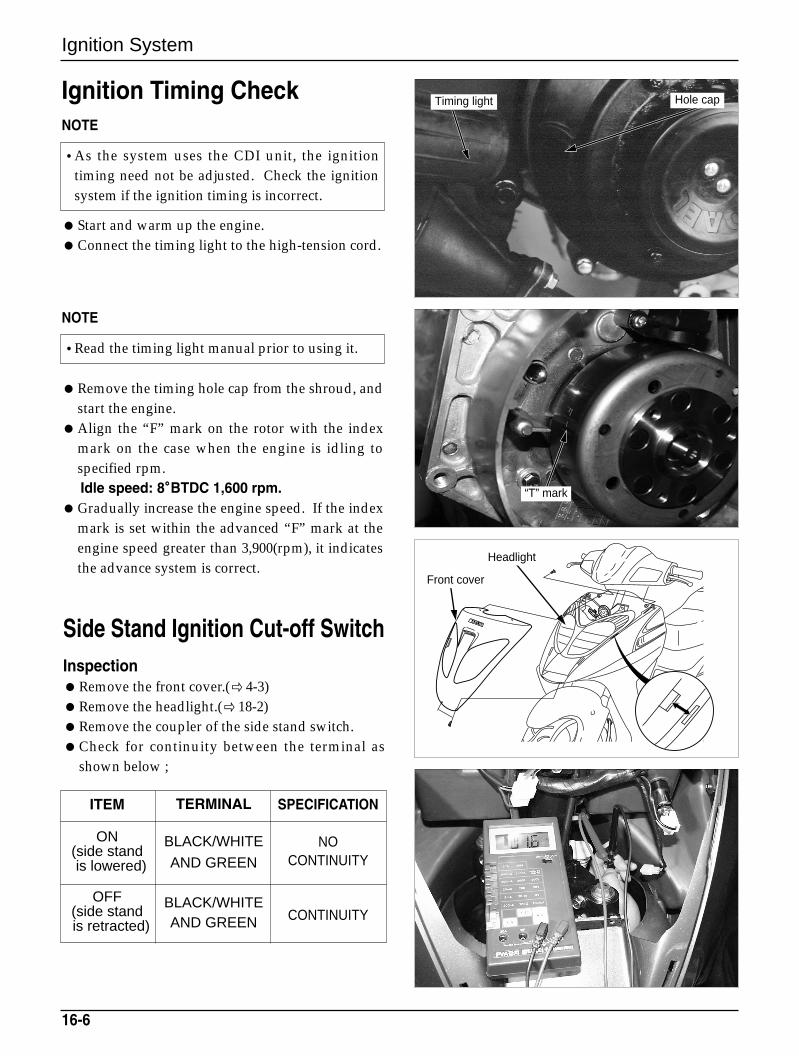
“T” mark
Front cover
Headlight
Ignition System
Ignition Timing CheckNOTE
Start and warm up the engine.Connect the timing light to the high-tension cord.
NOTE
Remove the timing hole cap from the shroud, andstart the engine.
Align the “F” mark on the rotor with the indexmark on the case when the engine is idling tospecified rpm.Idle speed: 8°°BTDC 1,600 rpm.
Gradually increase the engine speed. If the indexmark is set within the advanced “F” mark at theengine speed greater than 3,900(rpm), it indicatesthe advance system is correct.
Side Stand Ignition Cut-off SwitchInspectionRemove the front cover.( 4-3)Remove the headlight.(18-2)Remove the coupler of the side stand switch.Check for continuity between the terminal as
shown below ;
16-6
•As the system uses the CDI unit, the ignitiontiming need not be adjusted. Check the ignitionsystem if the ignition timing is incorrect.
•Read the timing light manual prior to using it.
Timing light Hole cap
ITEM
ON(side stand is lowered)
OFF(side stand is retracted)
TERMINAL
BLACK/WHITE
AND GREEN
BLACK/WHITEAND GREEN
SPECIFICATION
NOCONTINUITY
CONTINUITY
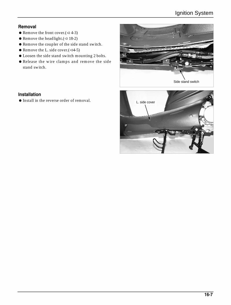
Ignition System
16-7
RemovalRemove the front cover.( 4-3)Remove the headlight.( 18-2)Remove the coupler of the side stand switch.Remove the L. side cover.(4-5)Loosen the side stand switch mounting 2 bolts. Release the wire clamps and remove the side
stand switch.
Installation Install in the reverse order of removal. L. side cover
Side stand switch

MEMO
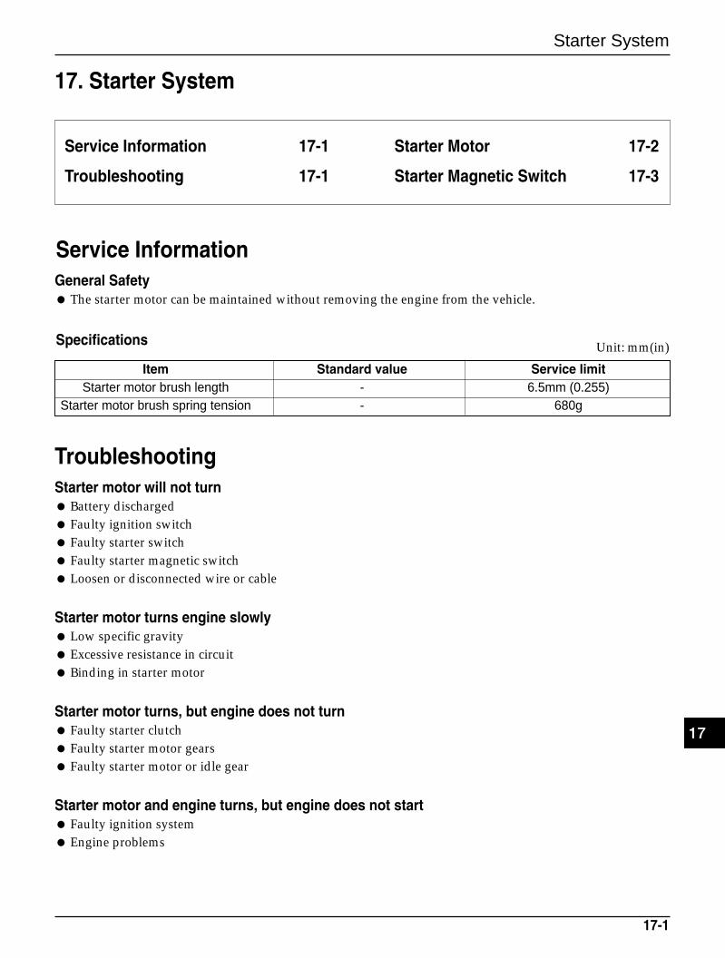
Starter System
17-1
17. Starter System
Service Information 17-1
Troubleshooting 17-1
Starter Motor 17-2
Starter Magnetic Switch 17-3
Service InformationGeneral Safety The starter motor can be maintained without removing the engine from the vehicle.
Item Standard value Service limitStarter motor brush length - 6.5mm (0.255)
Starter motor brush spring tension - 680g
Unit: mm(in)
TroubleshootingStarter motor will not turn Battery discharged Faulty ignition switch Faulty starter switch Faulty starter magnetic switch Loosen or disconnected wire or cable
Starter motor turns engine slowly Low specific gravity Excessive resistance in circuit Binding in starter motor
Starter motor turns, but engine does not turn Faulty starter clutch Faulty starter motor gears Faulty starter motor or idle gear
Starter motor and engine turns, but engine does not start Faulty ignition system Engine problems
Specifications
17
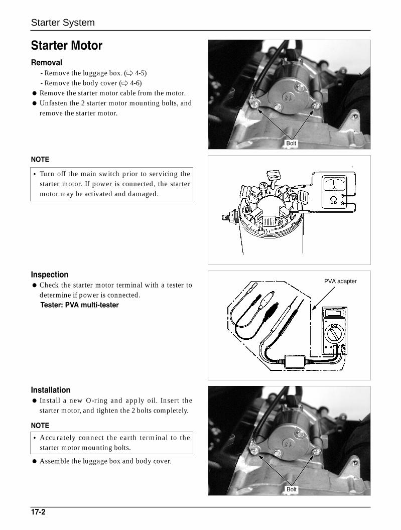
Starter System
Starter MotorRemoval
- Remove the luggage box. ( 4-5)- Remove the body cover ( 4-6)
Remove the starter motor cable from the motor. Unfasten the 2 starter motor mounting bolts, and
remove the starter motor.
NOTE
Inspection Check the starter motor terminal with a tester to
determine if power is connected.Tester: PVA multi-tester
Installation Install a new O-ring and apply oil. Insert the
starter motor, and tighten the 2 bolts completely.
NOTE
Assemble the luggage box and body cover.
17-2
• Accurately connect the earth terminal to thestarter motor mounting bolts.
• Turn off the main switch prior to servicing thestarter motor. If power is connected, the startermotor may be activated and damaged.
Bolt
Bolt
PVA adapter
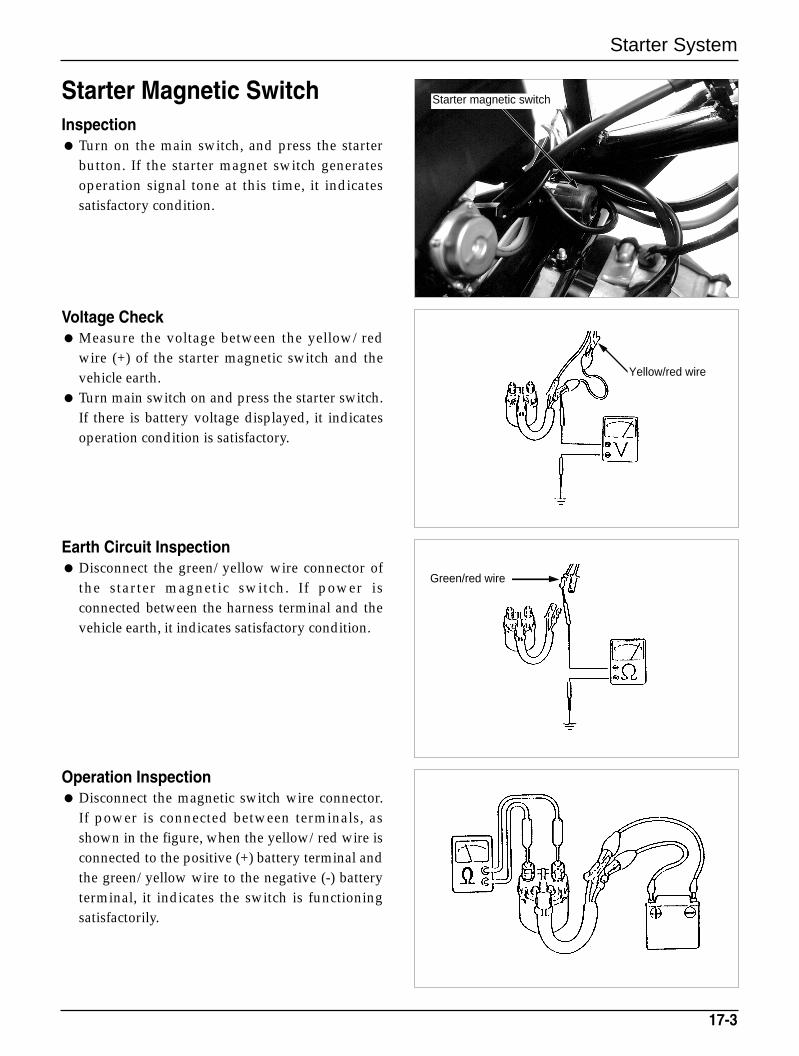
Starter System
Starter Magnetic SwitchInspection Turn on the main switch, and press the starter
button. If the starter magnet switch generatesoperation signal tone at this time, it indicatessatisfactory condition.
Voltage Check Measure the voltage between the yellow/red
wire (+) of the starter magnetic switch and thevehicle earth.
Turn main switch on and press the starter switch.If there is battery voltage displayed, it indicatesoperation condition is satisfactory.
Earth Circuit Inspection Disconnect the green/yellow wire connector of
the starter magnetic switch. If power isconnected between the harness terminal and thevehicle earth, it indicates satisfactory condition.
Operation Inspection Disconnect the magnetic switch wire connector.
If power is connected between terminals, asshown in the figure, when the yellow/red wire isconnected to the positive (+) battery terminal andthe green/yellow wire to the negative (-) batteryterminal, it indicates the switch is functioningsatisfactorily.
17-3
Starter magnetic switch
Yellow/red wire
Green/red wire

MEMO
Light/Switch/Horn
18-1
18. Light/Switch/Horn
Service Information 18-1
Troubleshooting 18-1
Headlight 18-2
Front Winker 18-2
Tail-Stop Light/Rear Winker 18-2
Meters(Measuring instruments) 18-3
Main Switch 18-4
Handle Bar Switch 18-4
Front Stop Light Switch 18-5
Fuel Gauge/Fuel Sensor 18-5
Horn/Clock 18-6
Clock 18-6
Trunk Lamp 18-7
Service InformationGeneral Safety Connect the same color wires together. Connect couplers carrying the same color and the same number of
pins together. All couplers are equipped with tabs which can be locked. Remove these locks prior to disassembling; and
insert these tabs all the way until locked when assembling. Carry out continuity test on circuits or parts to diagnose electric systems. The continuity test on normal
parts can be carried out without removing the parts from the vehicle. Simply disconnect the wires andconnect a continuity tester or an ohmmeter to the coupler terminals or connectors.
The continuity test is conducted to check if electric power is connected between 2 terminals. If there is coilresistance within circuits, or to check the large resistance resulting form the connector corrosion, anohmmeter is required to check the circuit resistance value.
Troubleshooting
Lights not turned on when the main switch is ON Faulty light bulb Faulty switch Faulty or disconnected wiring Fuse cut Battery discharged
Dim headlight Battery discharged Wiring and switch resistance high
Headlight Hi-Low bean cannot be changed Faulty light bulb Faulty dimmer switch
18
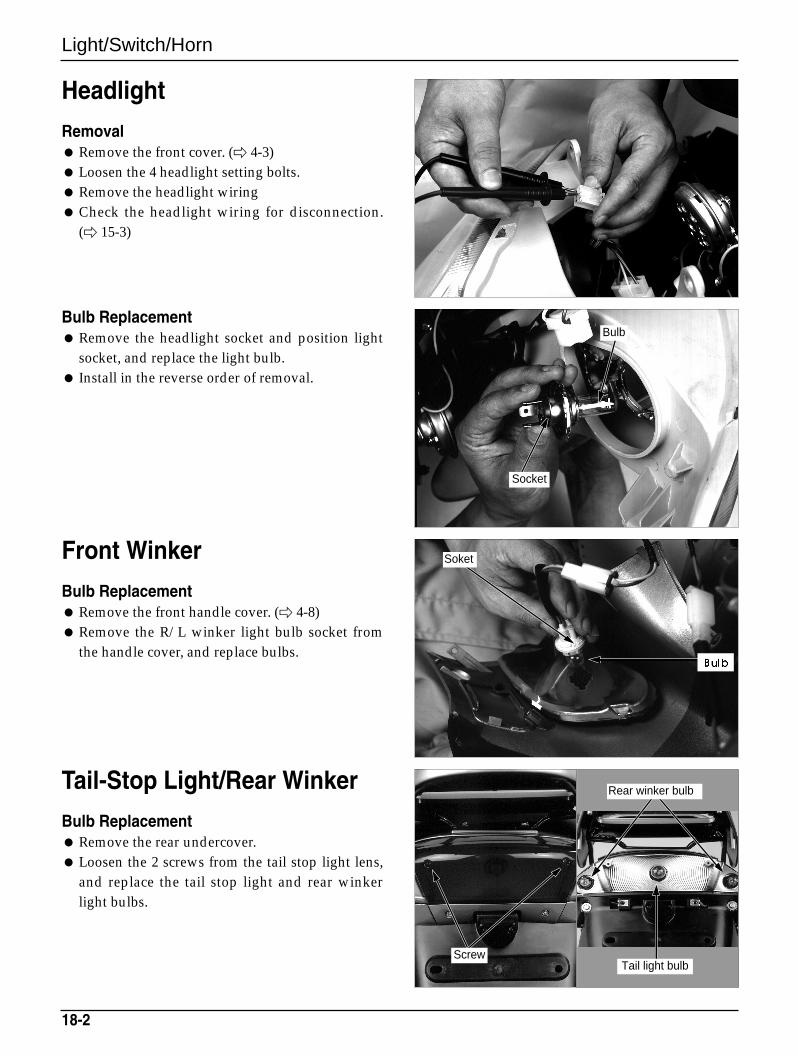
Light/Switch/Horn
Headlight
Removal Remove the front cover. ( 4-3) Loosen the 4 headlight setting bolts. Remove the headlight wiring Check the headlight wiring for disconnection.
( 15-3)
Bulb Replacement Remove the headlight socket and position light
socket, and replace the light bulb. Install in the reverse order of removal.
Front Winker
Bulb Replacement Remove the front handle cover. ( 4-8) Remove the R/L winker light bulb socket from
the handle cover, and replace bulbs.
Tail-Stop Light/Rear Winker
Bulb Replacement Remove the rear undercover. Loosen the 2 screws from the tail stop light lens,
and replace the tail stop light and rear winkerlight bulbs.
18-2
Bulb
Socket
Soket
Screw
Rear winker bulb
Tail light bulb
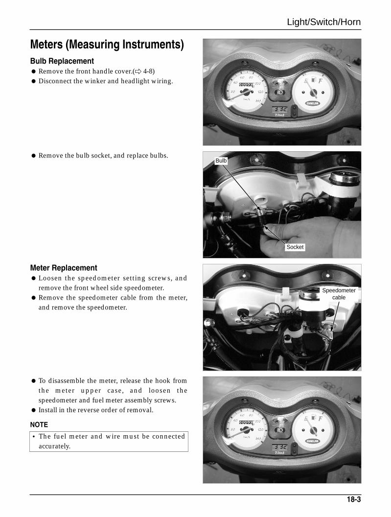
Light/Switch/Horn
Meters (Measuring Instruments)Bulb Replacement Remove the front handle cover.( 4-8) Disconnect the winker and headlight wiring.
Remove the bulb socket, and replace bulbs.
Meter Replacement Loosen the speedometer setting screws, and
remove the front wheel side speedometer. Remove the speedometer cable from the meter,
and remove the speedometer.
To disassemble the meter, release the hook fromthe meter upper case, and loosen thespeedometer and fuel meter assembly screws.
Install in the reverse order of removal.
NOTE
18-3
• The fuel meter and wire must be connectedaccurately.
Bulb
Socket
Speedometercable
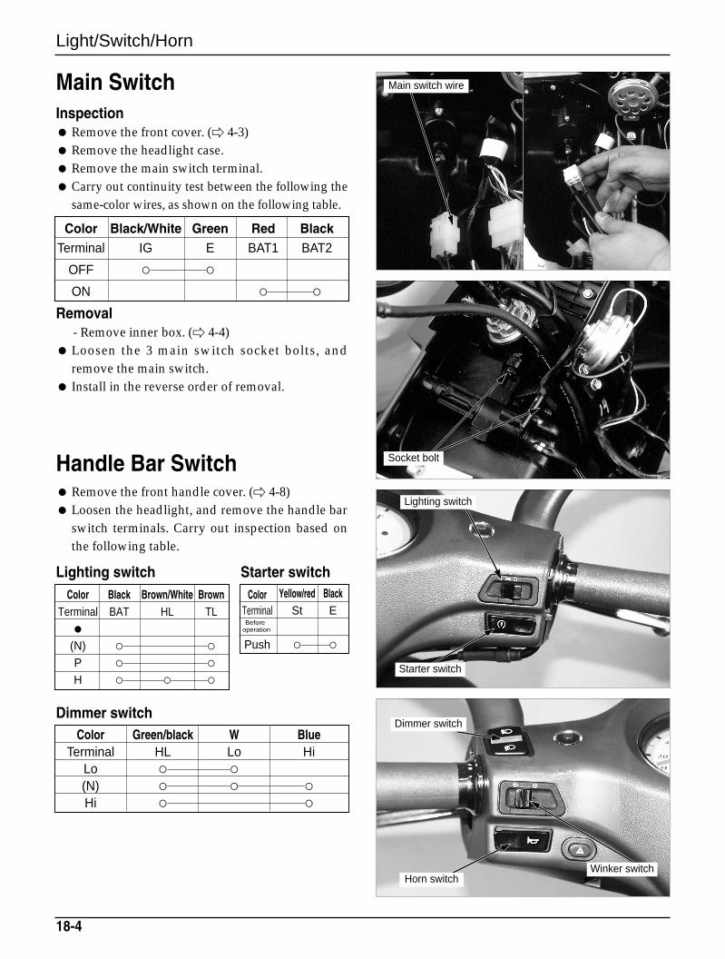
Light/Switch/Horn
Main SwitchInspection Remove the front cover. ( 4-3) Remove the headlight case. Remove the main switch terminal. Carry out continuity test between the following the
same-color wires, as shown on the following table.
Removal- Remove inner box. ( 4-4)
Loosen the 3 main switch socket bolts, andremove the main switch.
Install in the reverse order of removal.
Handle Bar Switch Remove the front handle cover. ( 4-8) Loosen the headlight, and remove the handle bar
switch terminals. Carry out inspection based onthe following table.
Dimmer switch
18-4
Color Black/White Green Red BlackTerminal IG E BAT1 BAT2
OFF
ON
Color Black Brown/White BrownTerminal BAT HL TL
(N)
P
H
Color Yellow/red BlackTerminal St E
Push
Color Green/black W BlueTerminal HL Lo Hi
Lo
(N)
Hi
Lighting switch Starter switch
Main switch wire
Socket bolt
Lighting switch
Starter switch
Dimmer switch
Winker switchHorn switch
Beforeoperation
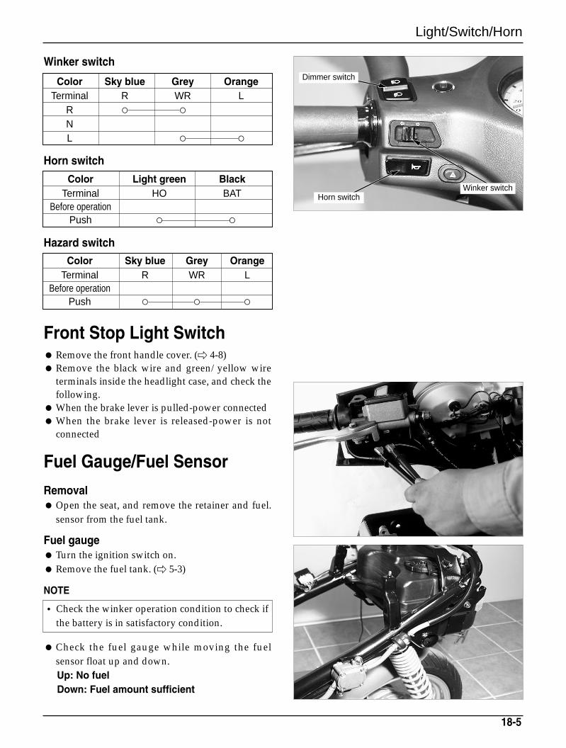
Light/Switch/Horn
Front Stop Light Switch Remove the front handle cover. ( 4-8) Remove the black wire and green/yellow wire
terminals inside the headlight case, and check thefollowing.
When the brake lever is pulled-power connected When the brake lever is released-power is not
connected
Fuel Gauge/Fuel Sensor
Removal Open the seat, and remove the retainer and fuel.
sensor from the fuel tank.
Fuel gauge Turn the ignition switch on. Remove the fuel tank. ( 5-3)
NOTE
Check the fuel gauge while moving the fuelsensor float up and down.Up: No fuelDown: Fuel amount sufficient
18-5
Winker switch
Color Sky blue Grey OrangeTerminal R WR L
R
NL
Horn switch
Color Light green BlackTerminal HO BAT
Before operationPush
Hazard switch
Color Sky blue Grey OrangeTerminal R WR L
Before operationPush
• Check the winker operation condition to check ifthe battery is in satisfactory condition.
Dimmer switch
Winker switchHorn switch
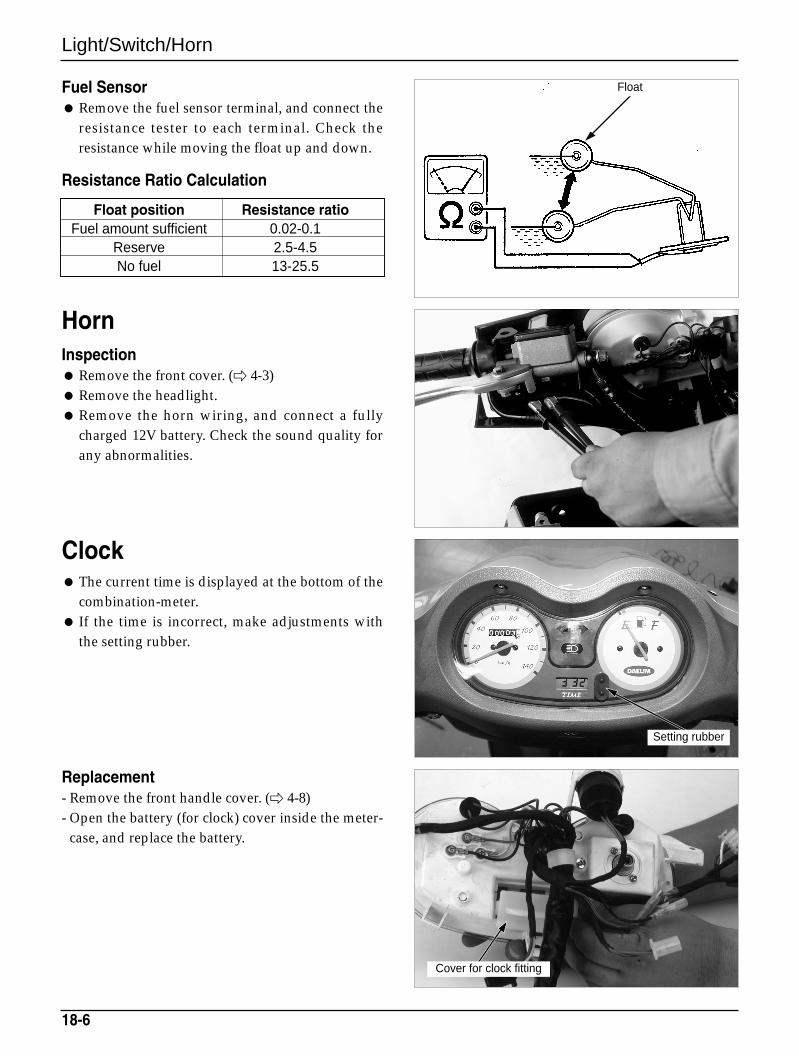
Light/Switch/Horn
Fuel Sensor Remove the fuel sensor terminal, and connect the
resistance tester to each terminal. Check theresistance while moving the float up and down.
HornInspection Remove the front cover. ( 4-3) Remove the headlight. Remove the horn wiring, and connect a fully
charged 12V battery. Check the sound quality forany abnormalities.
Clock The current time is displayed at the bottom of the
combination-meter. If the time is incorrect, make adjustments with
the setting rubber.
Replacement- Remove the front handle cover. ( 4-8)- Open the battery (for clock) cover inside the meter-
case, and replace the battery.
18-6
Float position Resistance ratioFuel amount sufficient 0.02-0.1
Reserve 2.5-4.5No fuel 13-25.5
Resistance Ratio Calculation
Setting rubber
Cover for clock fitting
Float
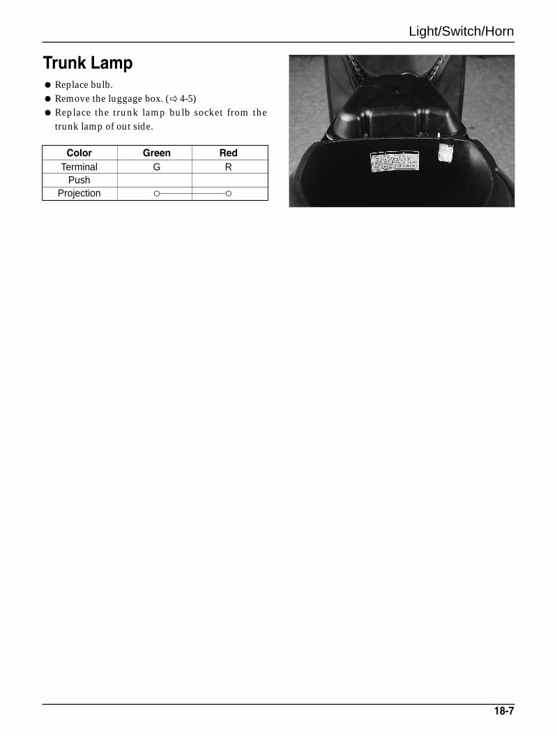
Light/Switch/Horn
18-7
Trunk Lamp Replace bulb. Remove the luggage box. ( 4-5) Replace the trunk lamp bulb socket from the
trunk lamp of out side.
Color Green RedTerminal G R
PushProjection

MEMO
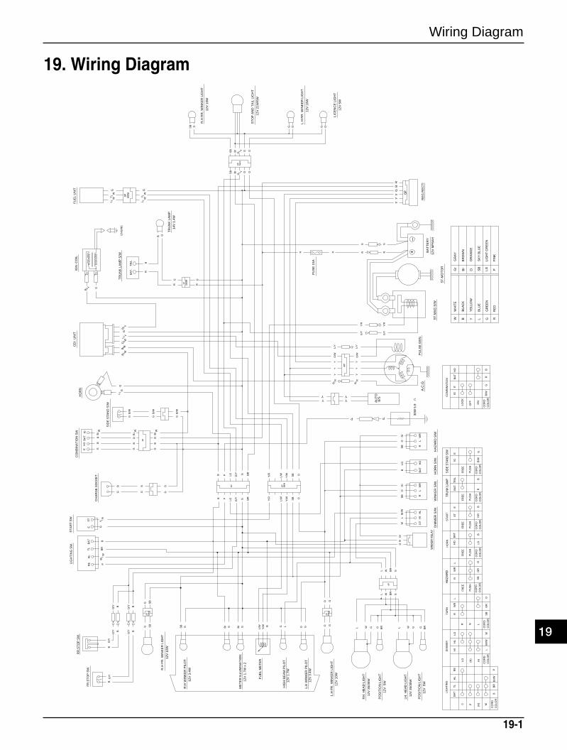
Wiring Diagram
19-1
19. Wiring Diagram
2P MIN
I
4P
6P MIN
I
LIG
HT
ING
BA
TT
L
P
ST
AR
T
ST
E
FR
EE
PU
SH
PU
SH
FR
EE
HO
BA
T
HO
RN
(N)
DIM
ME
R
HI
HL
LO
LO HI
TU
RN
RW
RL
R N L
W
W
HIT
EG
rG
RA
Y
B
B
LAC
K
YY
ELL
OW
LB
LUE
GG
RE
EN
RR
ED
Br
BR
OW
N
OO
RA
NG
E
SB
SK
Y B
LUE
LGLI
GH
T G
RE
EN
P
P
INK
4P
HL
LB
r/W
WC
OR
DC
OLO
RC
OR
DC
OLO
RG
RS
BO
CO
LOR
CO
RD
LGB
CO
RD
CO
LOR
Y/R
B
CO
RD
CO
LOR
4P
(N) M
BB
RB
r/W
6P MIN
I
6P
EN
GIN
E
MIN
I2P
WR
CO
LOR
CO
RD
SB
GR
R
OL
HA
ZA
RD
FR
EE
PU
SH
MIN
I2P
PRE
CO
LOR
CO
RD
PU
SH
FR
EE
BRB
AT
.T
R/L
TRU
NK
LA
MP
ON
CO
LOR
CO
RD
OF
F
LOC
K
GB
/WR
B
BA
T
HO
IG
E
CO
MB
INA
TIO
N
FR
EE
PU
SH
CO
RD
CO
LOR
B/W
SID
E S
TAN
D S
/W
IG
E
G
+_
YL/
YB
/ R
RE
G.R
EC
TI
YG
BR
BR/
L /Y
WB
/G
/B
Y
SB
G/ Y G O
OGY/GS
B
G GSB O
YB / G
CD
I U
NIT
IGN
. CO
ILH
OR
N
LOH
IB
AT
RL
WR
HO
WL
BS
BO
Gr
G
HO
BA
TE
IG
GB
/ WR
B
BA
TT
L
B
FR
.ST
OP
SW
.
CO
MB
INA
TIO
N S
W.
LIG
HT
ING
SW
.
HO
RN
S/W
.
G SB
Br G GBr
SB G O G
Br
Br
L/W B
SB
G
B
LG
LG
BB
G/Y
G/Y
GO
R/B
L/Y
Y
12V
MF
6AH
BA
TT
ER
Y
ST
-MO
TO
R
A.C
.G
R.H
RR
. WIN
KE
R L
IGH
T
12V
10W
ST
OP
AN
D T
AIL
LIG
HT
12V
21W
/5W
L.H
RR
. WIN
KE
R L
IGH
T
12V
10W
R.H
FR
. WIN
KE
R L
IGH
T
12V
10W
L.H
FR
. WIN
KE
R L
IGH
T
12V
10WFU
EL
ME
TE
R
ME
TE
R IL
LUM
INA
TIO
N12
V 1
.7W
x 2
R.H
WIN
KE
R P
ILO
T
12V
3.4
W
L.H
WIN
KE
R P
ILO
T
12V
3.4
W
HIG
H B
EA
M P
ILO
T
12
V 1
.7W
RH
. HE
AD
LIG
HT
12V
35/
35W
PU
LSE
GE
N.
6P
G/ W
HL
Br/
W
G/Y
BR
B
L GW BR
BR
GL W
LG L W G GWLY/W
Y YYY
G/W
G/W
Y/R
G/Y
G/Y
Y/R
YY
ST
-MA
G S
/W
PO
SIT
ION
LIG
HT
12V
5W
LH. H
EA
D L
IGH
T
12V
35/
35W
/ GL
SB O
Y/W
L/W
Y/R
B
RR
.ST
OP
SW
.
BR
Y/W SB OY/R
L/WB
R
G/Y GLGB
GG
r
WIN
KER
REL
AY
B
ST / R
YGE
HL /
Br
W
G/Y
G/Y B
B
/ WL
GY /
W
MIN
I
L/ W
G/
Y 3P
W
FU
EL
UN
IT
GB
RW
B/
G/
BW
RB
B/SY
AU
TOYY
G/Y
G/Y
OG
LIC
EN
CE
LIG
HT
12V
5W
ST
AR
T S
W.
DIM
ME
R S
/W.
WIN
KE
R S
/W.
GG
BRG
12V
5W
PO
SIT
ION
LIG
HT
G BR
R R
FU
SE
15A
R R
O G
Y
O LRSB
WR
Gr
HA
ZA
RD
S/W
B G
GR
GR
14V
1.4
W
TR
UN
K L
AM
P
TR
UN
K L
AM
P S
/WG
30W
5.9
P P
PRE
PP
RB
BA
T.
TR
/L
GB
CH
AR
GE
SO
CK
ET
G G
B/W
G
B/W
G
SID
E S
TA
ND
S/W
B/W
G
B B
19

MEMO
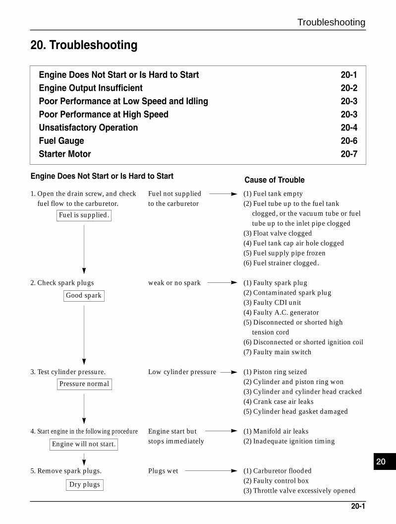
20-1
Engine Does Not Start or Is Hard to Start 20-1Engine Output Insufficient 20-2Poor Performance at Low Speed and Idling 20-3Poor Performance at High Speed 20-3Unsatisfactory Operation 20-4Fuel Gauge 20-6Starter Motor 20-7
Engine Does Not Start or Is Hard to Start
1. Open the drain screw, and check Fuel not supplied (1) Fuel tank emptyfuel flow to the carburetor. to the carburetor (2) Fuel tube up to the fuel tank
clogged, or the vacuum tube or fuel tube up to the inlet pipe clogged
(3) Float valve clogged(4) Fuel tank cap air hole clogged(5) Fuel supply pipe frozen(6) Fuel strainer clogged.
2. Check spark plugs weak or no spark (1) Faulty spark plug(2) Contaminated spark plug(3) Faulty CDI unit(4) Faulty A.C. generator(5) Disconnected or shorted high
tension cord(6) Disconnected or shorted ignition coil(7) Faulty main switch
3. Test cylinder pressure. Low cylinder pressure (1) Piston ring seized(2) Cylinder and piston ring won(3) Cylinder and cylinder head cracked(4) Crank case air leaks(5) Cylinder head gasket damaged
4. Start engine in the following procedure Engine start but (1) Manifold air leaksstops immediately (2) Inadequate ignition timing
5. Remove spark plugs. Plugs wet (1) Carburetor flooded(2) Faulty control box(3) Throttle valve excessively opened
Cause of Trouble
Fuel is supplied.
Good spark
Pressure normal
Engine will not start.
Dry plugs
20. Troubleshooting
20
Troubleshooting
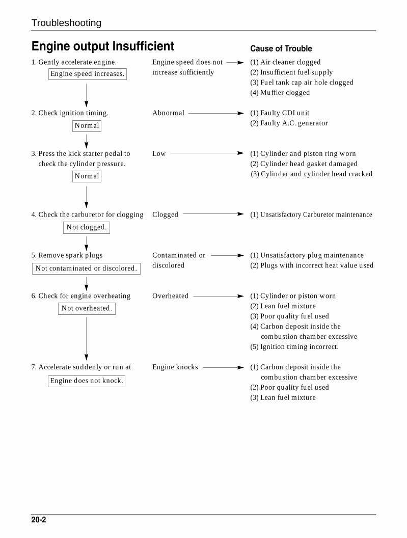
Troubleshooting
20-2
Engine output Insufficient1. Gently accelerate engine. Engine speed does not (1) Air cleaner clogged
increase sufficiently (2) Insufficient fuel supply(3) Fuel tank cap air hole clogged(4) Muffler clogged
2. Check ignition timing. Abnormal (1) Faulty CDI unit(2) Faulty A.C. generator
3. Press the kick starter pedal to Low (1) Cylinder and piston ring worncheck the cylinder pressure. (2) Cylinder head gasket damaged
(3) Cylinder and cylinder head cracked
4. Check the carburetor for clogging Clogged (1) Unsatisfactory Carburetor maintenance
5. Remove spark plugs Contaminated or (1) Unsatisfactory plug maintenancediscolored (2) Plugs with incorrect heat value used
6. Check for engine overheating Overheated (1) Cylinder or piston worn(2) Lean fuel mixture(3) Poor quality fuel used(4) Carbon deposit inside the
combustion chamber excessive(5) Ignition timing incorrect.
7. Accelerate suddenly or run at Engine knocks (1) Carbon deposit inside the combustion chamber excessive
(2) Poor quality fuel used(3) Lean fuel mixture
Engine speed increases.
Normal
Normal
Not clogged.
Not contaminated or discolored.
Not overheated.
Engine does not knock.
Cause of Trouble
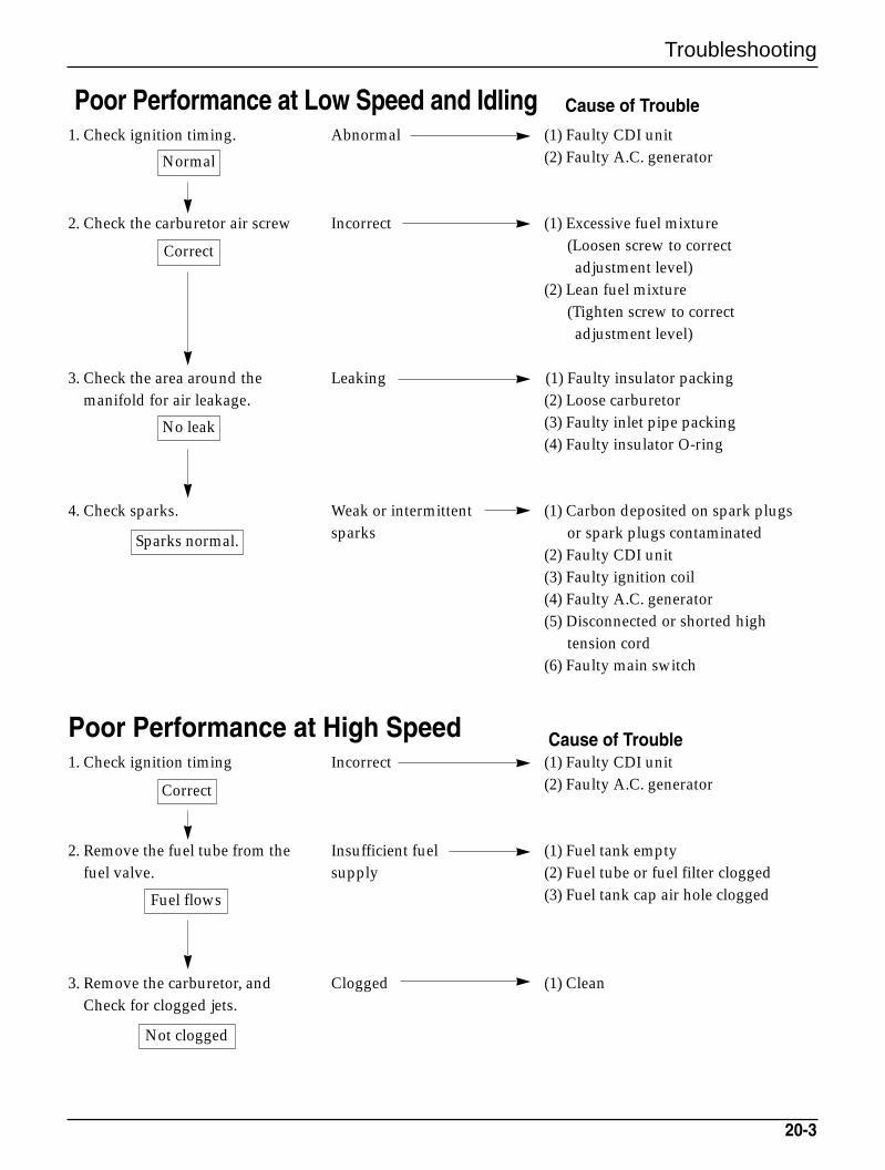
Troubleshooting
20-3
Poor Performance at Low Speed and Idling1. Check ignition timing. Abnormal (1) Faulty CDI unit
(2) Faulty A.C. generator
2. Check the carburetor air screw Incorrect (1) Excessive fuel mixture(Loosen screw to correct
adjustment level)(2) Lean fuel mixture
(Tighten screw to correct adjustment level)
3. Check the area around the Leaking (1) Faulty insulator packingmanifold for air leakage. (2) Loose carburetor
(3) Faulty inlet pipe packing(4) Faulty insulator O-ring
4. Check sparks. Weak or intermittent (1) Carbon deposited on spark plugs sparks or spark plugs contaminated
(2) Faulty CDI unit(3) Faulty ignition coil(4) Faulty A.C. generator(5) Disconnected or shorted high
tension cord(6) Faulty main switch
Poor Performance at High Speed1. Check ignition timing Incorrect (1) Faulty CDI unit
(2) Faulty A.C. generator
2. Remove the fuel tube from the Insufficient fuel (1) Fuel tank emptyfuel valve. supply (2) Fuel tube or fuel filter clogged
(3) Fuel tank cap air hole clogged
3. Remove the carburetor, and Clogged (1) CleanCheck for clogged jets.
Correct
Normal
No leak
Sparks normal.
Correct
Fuel flows
Not clogged
Cause of Trouble
Cause of Trouble
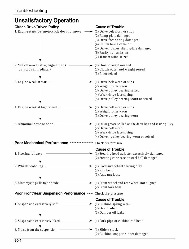
Troubleshooting
20-4
Unsatisfactory OperationClutch Drive/Driven Pulley1. Engine starts but motorcycle does not move. (1) Drive belt worn or slips
(2) Ramp plate damaged(3) Drive face spring damaged(4) Clutch lining came off(5) Driven pulley shaft spline damaged(6) Faulty transmission(7) Transmission seized
2. Vehicle moves slow, engine starts (1) Shoe spring damagedbut stops immediately (2) Clutch outer and weight seized
(3) Pivot seized
3. Engine weak at start. (1) Drive belt worn or slips(2) Weight roller worn(3) Drive pulley bearing seized(4) Weak drive face spring(5) Drive pulley bearing worn or seized
4. Engine weak at high speed. (1) Drive belt worn or slips(2) Weight roller worn(3) Drive pulley bearing worn
5. Abnormal noise or odor. (1) Oil or grease spilled on the drive belt and inside pulley(2) Drive belt worn(3) Weak drive face spring(4) Driven pulley bearing worn or seized
Poor Mechanical Performance Check tire pressure
1. Steering is heavy (1) Steering head adjuster excessively tightened(2) Steering cone race or steel ball damaged
2. Wheels wobbling (1) Excessive wheel bearing play(2) Rim bent(3) Axle nut loose
3. Motorcycle pulls to one side (1) Front wheel and rear wheel not aligned(2) Front fork bent
Poor Front/Rear Suspension Performance Check tire pressure
1. Suspension excessively soft (1) Cushion spring weak(2) Overloaded(3) Damper oil leaks
2. Suspension excessively Hard (1) Fork pipe or cushion rod bent
3. Noise from the suspension (1) Sliders stuck(2) Cushion stopper rubber damaged
Cause of Trouble
Cause of Trouble
Cause of Trouble
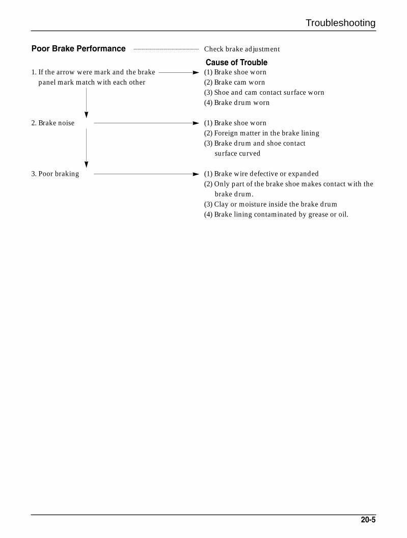
Troubleshooting
20-5
Poor Brake Performance Check brake adjustment
1. If the arrow were mark and the brake (1) Brake shoe wornpanel mark match with each other (2) Brake cam worn
(3) Shoe and cam contact surface worn(4) Brake drum worn
2. Brake noise (1) Brake shoe worn(2) Foreign matter in the brake lining(3) Brake drum and shoe contact
surface curved
3. Poor braking (1) Brake wire defective or expanded(2) Only part of the brake shoe makes contact with the
brake drum.(3) Clay or moisture inside the brake drum(4) Brake lining contaminated by grease or oil.
Cause of Trouble
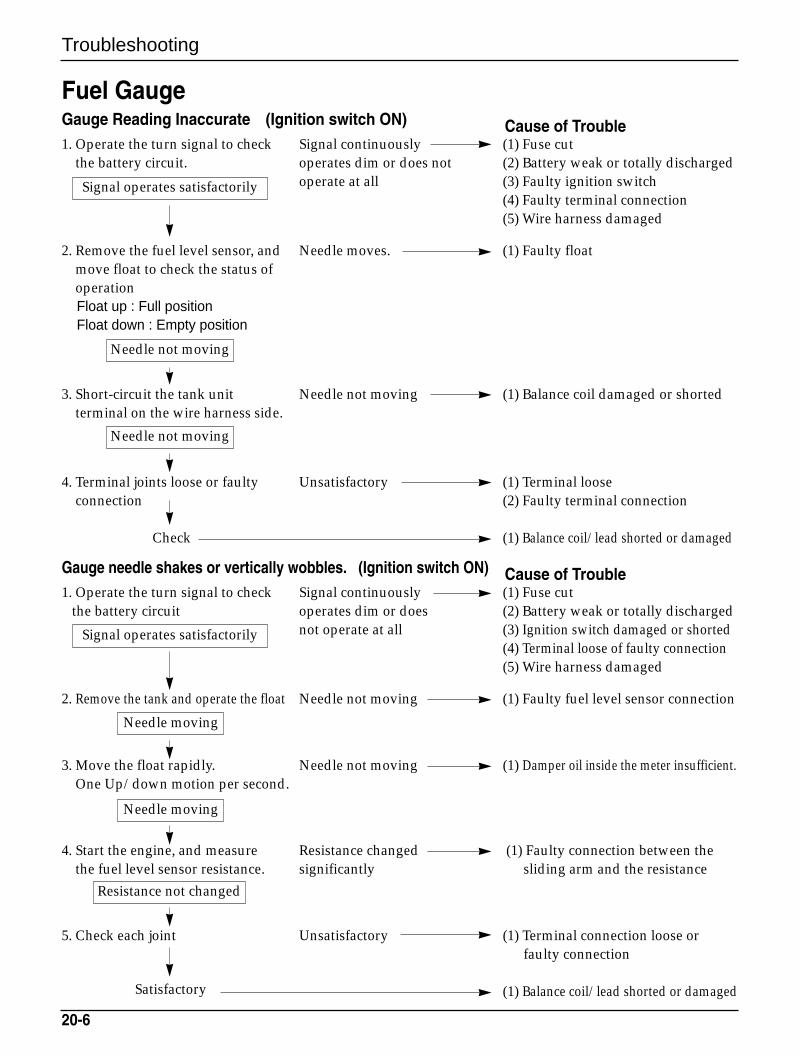
Troubleshooting
20-6
Fuel GaugeGauge Reading Inaccurate (Ignition switch ON)1. Operate the turn signal to check Signal continuously (1) Fuse cut
the battery circuit. operates dim or does not (2) Battery weak or totally dischargedoperate at all (3) Faulty ignition switch
(4) Faulty terminal connection(5) Wire harness damaged
2. Remove the fuel level sensor, and Needle moves. (1) Faulty floatmove float to check the status of operationFloat up : Full positionFloat down : Empty position
3. Short-circuit the tank unit Needle not moving (1) Balance coil damaged or shortedterminal on the wire harness side.
4. Terminal joints loose or faulty Unsatisfactory (1) Terminal looseconnection (2) Faulty terminal connection
(1) Balance coil/lead shorted or damaged
Gauge needle shakes or vertically wobbles. (Ignition switch ON)1. Operate the turn signal to check Signal continuously (1) Fuse cut
the battery circuit operates dim or does (2) Battery weak or totally dischargednot operate at all (3) Ignition switch damaged or shorted
(4) Terminal loose of faulty connection(5) Wire harness damaged
2. Remove the tank and operate the float Needle not moving (1) Faulty fuel level sensor connection
3. Move the float rapidly. Needle not moving (1) Damper oil inside the meter insufficient.One Up/down motion per second.
4. Start the engine, and measure Resistance changed (1) Faulty connection between the the fuel level sensor resistance. significantly sliding arm and the resistance
5. Check each joint Unsatisfactory (1) Terminal connection loose or faulty connection
(1) Balance coil/lead shorted or damaged
Signal operates satisfactorily
Signal operates satisfactorily
Needle not moving
Needle not moving
Needle moving
Needle moving
Satisfactory
Resistance not changed
Check
Cause of Trouble
Cause of Trouble
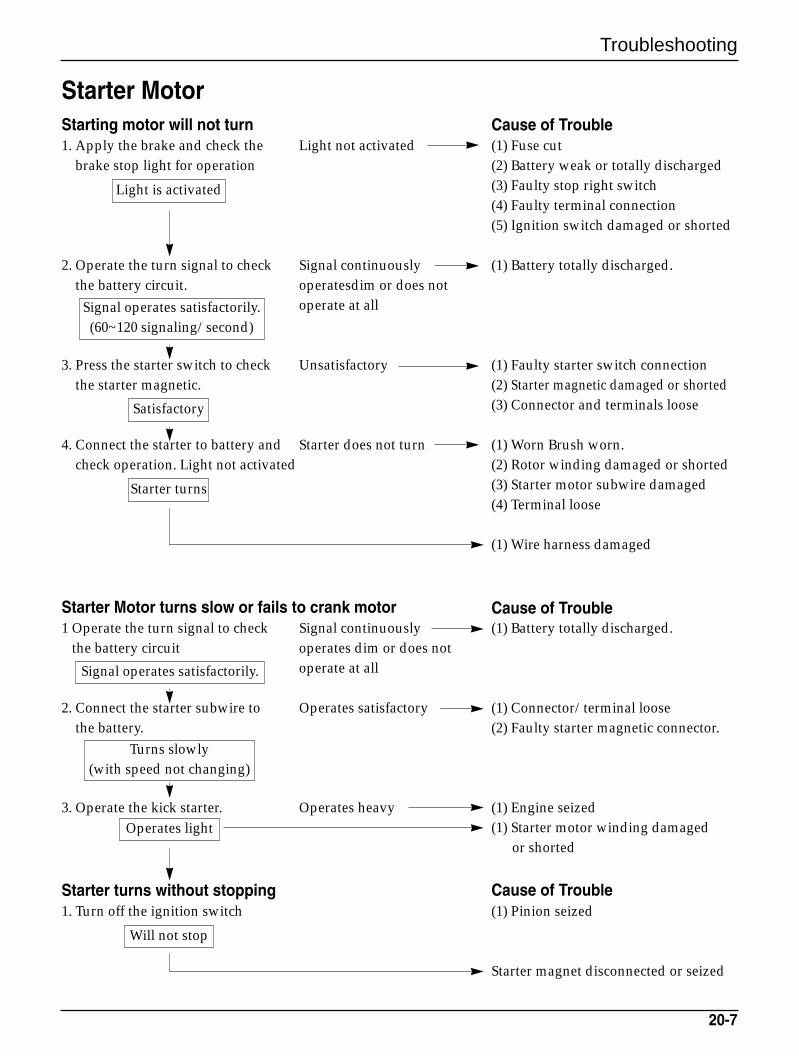
Troubleshooting
20-7
Starter MotorStarting motor will not turn1. Apply the brake and check the Light not activated (1) Fuse cut
brake stop light for operation (2) Battery weak or totally discharged(3) Faulty stop right switch(4) Faulty terminal connection(5) Ignition switch damaged or shorted
2. Operate the turn signal to check Signal continuously (1) Battery totally discharged.the battery circuit. operatesdim or does not
operate at all
3. Press the starter switch to check Unsatisfactory (1) Faulty starter switch connectionthe starter magnetic. (2) Starter magnetic damaged or shorted
(3) Connector and terminals loose
4. Connect the starter to battery and Starter does not turn (1) Worn Brush worn.check operation. Light not activated (2) Rotor winding damaged or shorted
(3) Starter motor subwire damaged(4) Terminal loose
(1) Wire harness damaged
Starter Motor turns slow or fails to crank motor1 Operate the turn signal to check Signal continuously (1) Battery totally discharged.
the battery circuit operates dim or does not operate at all
2. Connect the starter subwire to Operates satisfactory (1) Connector/terminal loosethe battery. (2) Faulty starter magnetic connector.
3. Operate the kick starter. Operates heavy (1) Engine seized(1) Starter motor winding damaged
or shorted
Starter turns without stopping1. Turn off the ignition switch (1) Pinion seized
Starter magnet disconnected or seized
Light is activated
Satisfactory
Starter turns
Signal operates satisfactorily.(60~120 signaling/second)
Signal operates satisfactorily.
Operates light
Will not stop
Turns slowly(with speed not changing)
Cause of Trouble
Cause of Trouble
Cause of Trouble
2001. 4. PRINTED2001. 4. PUBLICATION
SERVICE MANUAL
NO COPY
SM41-0104-01E
••HEAD OFFICE(FACTORY) : #58, Sungsan-dong, Changwon, Kyungnam, Korea
Tel : (82-55)279-7000 / Fax : (82-55)239-7524••OVERSEAS SALES OFFICE
: #16-6 Pil-dong 2Ka, Chung-ku, Seoul, KoreaTel : (82-2)2274-3171 / Fax : (82-2)2269-7997