Embed Size (px)
Citation preview
Dalhousie University – Mechanical Engineering
MECH 4830 – Energy Management
Cooling Towers
February 13, 2015
Greg Donovan
Meagan Buchanan
MECH 4340 – Energy Management M. Buchanan Cooling Towers G. Donovan
Dalhousie University Department of Mechanical Engineering Page 2 of 32
Table of Contents
List of Figures ................................................................................................................................................ 3
Abstract ......................................................................................................................................................... 4
1. Introduction ........................................................................................................................................ 5
2. Operating Conditions .......................................................................................................................... 8
3. Cooling Tower Types ......................................................................................................................... 10
3.1. Natural Draft Cooling Towers ................................................................................................... 11
3.2. Mechanical Draft Cooling Tower .............................................................................................. 12
3.3. Cooling fluids ............................................................................................................................. 13
4. Cooling Tower Components ............................................................................................................. 15
4.1. Drive Systems ............................................................................................................................ 17
4.2. Driven Systems .......................................................................................................................... 20
4.3. Fixed Equipment ....................................................................................................................... 25
5. Summary ........................................................................................................................................... 28
References .................................................................................................................................................. 32
MECH 4340 – Energy Management M. Buchanan Cooling Towers G. Donovan
Dalhousie University Department of Mechanical Engineering Page 3 of 32
List of Figures
Figure 1: Cooling Tower Characteristics Curve ............................................................................................. 6
Figure 2 : Cooling tower cell with multiple fans [2] ...................................................................................... 9
Figure 3 – Wet cooling tower representation [5] ....................................................................................... 15
Figure 4 : Air Cooled Heat Exchanger Representation [9] .......................................................................... 16
Figure 5: Two rotor turbine with cover removed [12] ................................................................................ 19
Figure 6 : Cutaway of centrifugal pump [13] .............................................................................................. 21
Figure 7 - Simplified pump and heat exchanger network of a cooling water system [12] ......................... 22
MECH 4340 – Energy Management M. Buchanan Cooling Towers G. Donovan
Dalhousie University Department of Mechanical Engineering Page 4 of 32
Abstract
Cooling Towers, are used in different applications worldwide for process cooling purposes. These
applications include power plants, oil refineries, chemical plants and even building cooling. This
report will delve into how cooling towers function, different types of cooling towers including wet
cooling and dry cooling and different airflow types of the coolers including cross and counter flow
towers. This report discusses the different components of the cooling towers including the fixed
equipment, the drive and driven equipment.
A discussion of fixed equipment including the piping network of wet cooling towers, including
problems with corrosion in the pipes due to the microbial content of the water is performed. The air
cooled heat exchanger tube bank fin types and fouling are also discussed.
Drive systems of motors and turbines are discussed. The types of motors used in cooling towers are
explained and the gains of motor efficiency increases are explored. Turbine drives are also discussed
with the fundamental operation and benefits to turbine use outlined.
Driven systems of fan drives and pumps are considered. Efficiency gains from different fan blades,
installation and alignment and belt types are shown. The different types of pumps used in cooling
towers are outlined and the importance of pump network configuration discussed.
MECH 4340 – Energy Management M. Buchanan Cooling Towers G. Donovan
Dalhousie University Department of Mechanical Engineering Page 5 of 32
1. Introduction
Cooling towers are used to reject heat from industrial and commercial processes as required. This is
performed by transferring heat from a cooling fluid, typically water, but occasionally air or another
fluid, by means of an interfacial film. This heat is then transferred from the film to air by typical heat
transfer, or evaporative methods. [1] The amount of heat transferred from the cooing fluid must be
equal to that of the heat absorbed by the air flowing through the tower. This heat transfer can be
represented by the following equation:
𝐿
𝐺=
ℎ2 − ℎ1
𝑇1 − 𝑇2
Where L/G represents the liquid to gas ratio of water to dry air, h represents the enthalpy at the
exhaust and inlet wet bulb temperatures and the temperatures of the hot and cold waters. [1] This
equation is typically used to express the cooling tower characteristics. This equation can also be
related to the following equation:
𝐾𝑎𝑉
𝐿= ∫
𝑑𝑇
ℎ𝑤 − ℎ𝑎
𝑇1
𝑇2
Which represents the heat transfer obtained from the transfer of sensible heat and the evaporation
of water. KaV/L represents the cooling tower characteristics. [1]With these two equations known it
is possible, in a similar manner to that of steam tables, to predict the cooling tower performances by
use of Figure 1, from the Standard Handbook of Plant Engineering book below.
MECH 4340 – Energy Management M. Buchanan Cooling Towers G. Donovan
Dalhousie University Department of Mechanical Engineering Page 6 of 32
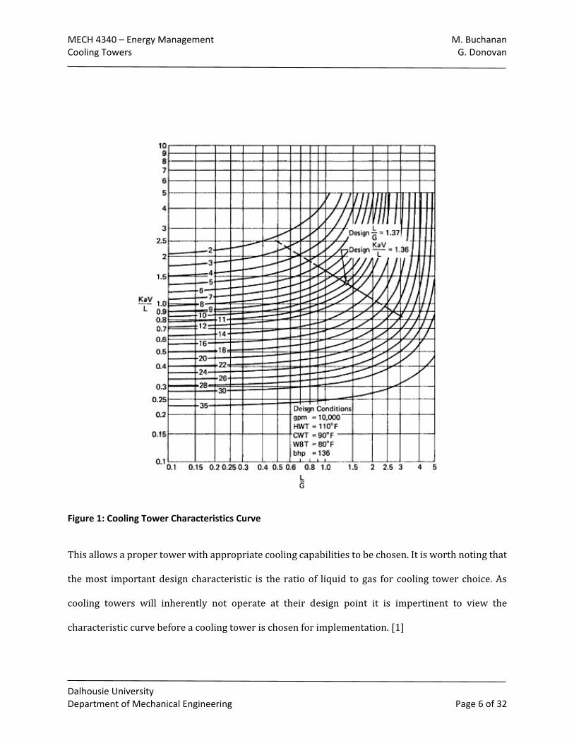
Figure 1: Cooling Tower Characteristics Curve
This allows a proper tower with appropriate cooling capabilities to be chosen. It is worth noting that
the most important design characteristic is the ratio of liquid to gas for cooling tower choice. As
cooling towers will inherently not operate at their design point it is impertinent to view the
characteristic curve before a cooling tower is chosen for implementation. [1]
MECH 4340 – Energy Management M. Buchanan Cooling Towers G. Donovan
Dalhousie University Department of Mechanical Engineering Page 7 of 32
Cooling tower operation has certain loss factors that should be accounted for. This includes losses
such as evaporation loss due to the increase of heat into the cooling water. Another loss that should
be considered is drift loss from the water vapour that will be present in the exhaust airflow from the
tower, and blowdown losses which is from water that is discharged to prevent mineral or solid
buildup in the cooling water. To account for these losses make-up water must be added to the system.
The amount of make-up water required can be determined by using rules of thumbs to determine
the amount of water from the above losses.
MECH 4340 – Energy Management M. Buchanan Cooling Towers G. Donovan
Dalhousie University Department of Mechanical Engineering Page 8 of 32
2. Operating Conditions
Cooling towers typically run well under what would be considered normal ambient conditions, which
would include average temperatures above zero and little precipitation. These conditions represent
the design conditions of the cooling towers and are when the tower would experience maximum
efficiency. However, these ideal conditions do not exist for some regions of the world for at least half
of the year. Canada would be an excellent example of this an atypical climate from the original design
climate.
The atypical climate conditions require that special precautions be taken into account to operate
cooling towers in regions with colder weather. The threshold for sustained freezing conditions is
more than 24 hours below zero, and no freeze thaw cycle in effect. [2] During these conditions it is
required to maintain the proper heat load, this will prevent wet cooling towers from having the water
freeze when it passes through the exchanger. If this heat load cannot be maintained it is important to
bypass the tower to prevent any damage to the equipment. It is vitally important to inspect the
towers during colder months to ensure that there is no ice buildup. [2]
It is also important to run the cooling towers under the intended manufacturer operating conditions.
This includes ensuring that the minimum or more water flow rate is obtained over the cooling tower.
This may decrease efficiency of the tower but will prevent damage to the equipment. [2]
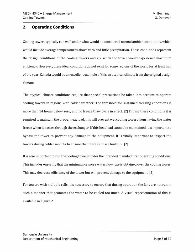
For towers with multiple cells it is necessary to ensure that during operation the fans are not run in
such a manner that promotes the water to be cooled too much. A visual representation of this is
available in Figure 2.
MECH 4340 – Energy Management M. Buchanan Cooling Towers G. Donovan
Dalhousie University Department of Mechanical Engineering Page 9 of 32
Figure 2 : Cooling tower cell with multiple fans [2]
As shown above, if only one fan is run in a cell there is the potential that the water in the third cell
could be freezing, as it is close to the freezing point. To counteract this effect, often variable speed
drives are placed on each of the fan cells and are all run at the same speed. This enables all the fans
to be running and prevents the temperature gradient difference. [2]
To increase general fan efficiency during winter months fan blade pitch can be adjusted to account
for the difference in the air density between warm and cold weather application. Re-pitching the fan
depending on the weather conditions can add unwanted maintenance costs that can counteract the
efficiency gains. Adjusting fan pitches that have never been re-pitched can also cause cracking along
the hub or blades and lead to failures. This is why most users will leave the fan pitched at the design
maximum, which is less efficient for atypical climate, and use variable speed drives to mitigate the
freezing conditions. [3]
MECH 4340 – Energy Management M. Buchanan Cooling Towers G. Donovan
Dalhousie University Department of Mechanical Engineering Page 10 of 32
3. Cooling Tower Types
There are different types of cooling towers currently in application, mostly depending on the location
and resources available. There are natural draft cooling devices such as pond cooling, spray and wood
filled atmospheric cooling and chimney towers. Predominately in oil refineries mechanical draft
cooling towers are employed as they allow the amount of air supply to be controlled using a fan.
There are different configurations of the mechanical draft cooling towers that can be implemented,
once again depending on the types of resources available. [4] The main differences in system designs
include wet cooling versus dry cooling, the manner in which air is induced into the system, either
forced or induced draft and the difference in the manner the air flows through the cooling system
either in a counter or cross flow. [4]

MECH 4340 – Energy Management M. Buchanan Cooling Towers G. Donovan
Dalhousie University Department of Mechanical Engineering Page 11 of 32
3.1. Natural Draft Cooling Towers
Natural draft cooling towers do not use any mechanical device such as a fan to achieve airflow
throughout the tower. These devices can be configured in manners such as an atmospheric spray
tower, which has the airflow travel through a spray of water, or a draft tower where water is added
to a natural flow of air for cooling. [5] Another type of natural draft cooling towers is a dry manner
in which a hot fluid flows through radiators where airflow flows over the radiators to cool the fluid.
Natural draft cooling towers are typically employed at steam power plants for cooling purposes. [6]
Natural draft cooling towers loose cooling efficiency as crosswind velocities increase. Traditional
natural draft cooling towers are design to run most efficiently at wind speeds of approximately 3m/s
(or 7 mph), wind breakers either in a radiator or solid fashion can be implemented to decelerate
airflow, increasing efficiencies up to 9%. [6] A study performed by M. Goodarzi and R. Ramezanpour
have explored alternative geometries of the natural draft cooling towers to improve cooling
efficiencies when the towers are subjected to a crosswind. It was determined that for wind speeds of
approximately 10m/s (or 22 mph) the cooling efficiency of round cooling towers increased from
80.7% to 84.4% (+3.7%) for an elliptical cooling towers with a diameter ratio of 0.75, and 91.8%
(+11.1%) for a cooling tower with an elliptical cross section of 0.50. [6]
MECH 4340 – Energy Management M. Buchanan Cooling Towers G. Donovan
Dalhousie University Department of Mechanical Engineering Page 12 of 32
3.2. Mechanical Draft Cooling Tower
Mechanical draft cooling towers employ fans to regulate the volume of air that is passed over the
fluid requiring cooling. This means that mechanical tower cooling efficiencies are considered to have
much more stable values as they do not depend on wind speed like the natural draft cooling towers.
The fan cooling present in mechanical draft towers means the cooling system will be subject from
less change due to atmospheric conditions. Mechanical cooling towers can be forced or induced draft,
and can be either wet or dry cooling systems. [5]
3.2.1. Mechanical Draft Variations
There are different types of mechanical draft coolers. There are induced and forced draft coolers, this
indicates how the airflow is drawn over the cooler. Induced draft coolers use a fan at the exit of a
cooler to create airflow. Forced draft coolers use a fan at the inlet of the cooler to force airflow
through the cooler. [4]
Mechanical draft coolers also vary in the manner of which the air is airflow is directed over the
cooling exchange. The coolers can either have a counter or cross flow airflow in the cooler. A counter
flow cooling tower has airflow in the vertical direction to the main flow of fluid needing to be cooled.
A cross flow cooling tower has airflow in the horizontal direction to the main flow of fluid needing to
be cooled. Cross flow cooling towers can also be considered either single or double flow towers. A
single flow tower consists of only a single inlet, while double flow will have two inlets. [5]
MECH 4340 – Energy Management M. Buchanan Cooling Towers G. Donovan
Dalhousie University Department of Mechanical Engineering Page 13 of 32
3.3. Cooling fluids
Cooling towers require a medium to extract heat from the process fluid. This can be achieved with
either liquids such as water or dry fluids such as air depending on which is more accessible in the
needed application. Air cooling towers are typically referred to as air cooled heat exchangers.
Water used in wet cooling towers can have issues of fouling due to the hardness of the water often
used. Water in cooling towers are often treated with corrosion and biological growth inhibitors,
meaning that this mineral buildup tends to have the highest effect on water losses of the towers, by
requiring either a water treatment plant to be put in place or more makeup water to be added to the
systems. A study that was conducted concluded that for a small scale 3 ton cooling tower the
mineralized calcium levels increased by six times over a two month period. [7]
Water cooled systems will use less overall energy than air cooled heat exchangers, and there are
many energy efficiency gains that can be attributed for both systems from more efficient
technologies. [8]
Air cooled heat exchangers will have a higher capital cost than a water cooling tower alternative, the
cost to provide water to the wet system along with increased maintenance costs can make the dry
system have a lower lifetime running cost. Depending on the availability of water it may be more
desirable to implement a dry system to conserve water [9]
It is important to note that air cooled heat exchangers should not have water added to increase the
cooling capabilities as the systems are not designed for this. The action of spraying water on the
exchangers is commonly referred to as “California Cooling”. It can cause the finned tubes of the
exchanger to separate, due to being rapidly cooled by the water. This expansion allows water to seep
in between the fins and will decrease the heat exchange between the air and the tubes by created an
MECH 4340 – Energy Management M. Buchanan Cooling Towers G. Donovan
Dalhousie University Department of Mechanical Engineering Page 14 of 32
insulated region around the tubes. The water may also create a build-up of calcium carbonate and
other deposits which will also decrease the cooling capabilities of the tube bank exchanger. This will
lead to the need of the replacement of the entire tube bank, which can be very costly and is not
justified by any short term efficiency gains obtained from the water spray. [3]
MECH 4340 – Energy Management M. Buchanan Cooling Towers G. Donovan
Dalhousie University Department of Mechanical Engineering Page 15 of 32
4. Cooling Tower Components
Systems such as cooling towers require different components to run. The equipment required can be
broken down into the following main systems: fixed equipment, such as piping, mechanical systems
such as drives and air circulation systems.
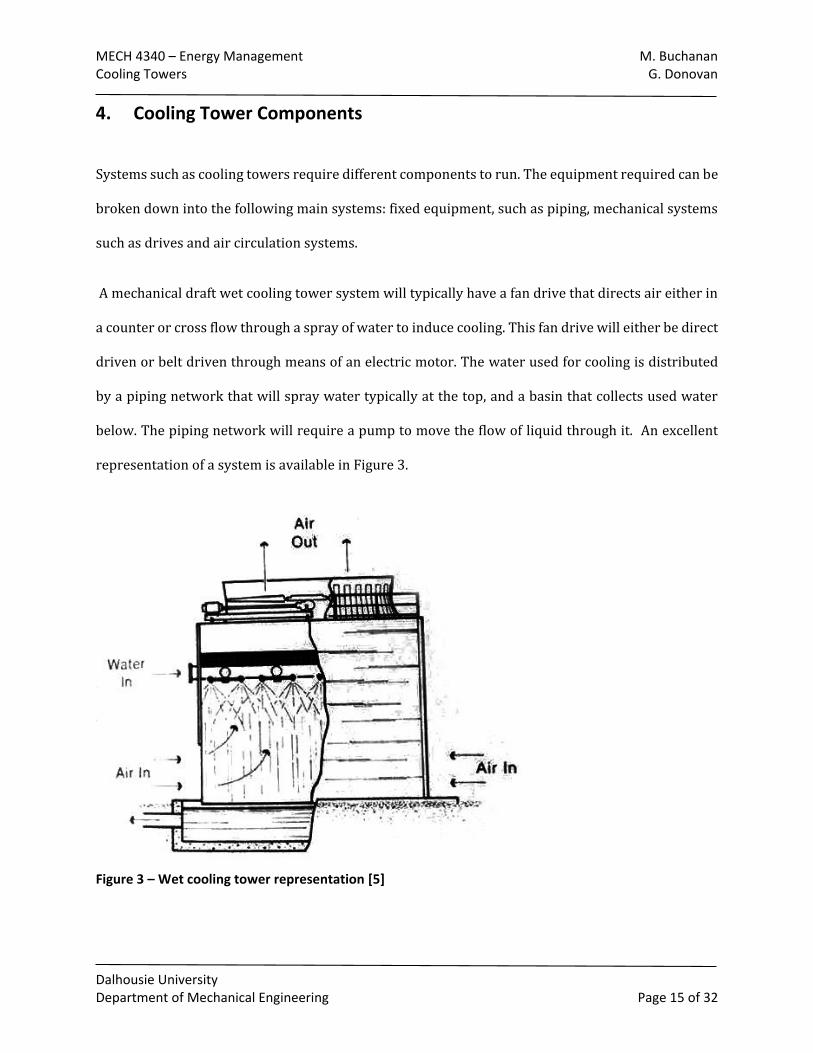
A mechanical draft wet cooling tower system will typically have a fan drive that directs air either in
a counter or cross flow through a spray of water to induce cooling. This fan drive will either be direct
driven or belt driven through means of an electric motor. The water used for cooling is distributed
by a piping network that will spray water typically at the top, and a basin that collects used water
below. The piping network will require a pump to move the flow of liquid through it. An excellent
representation of a system is available in Figure 3.
Figure 3 – Wet cooling tower representation [5]
MECH 4340 – Energy Management M. Buchanan Cooling Towers G. Donovan
Dalhousie University Department of Mechanical Engineering Page 16 of 32
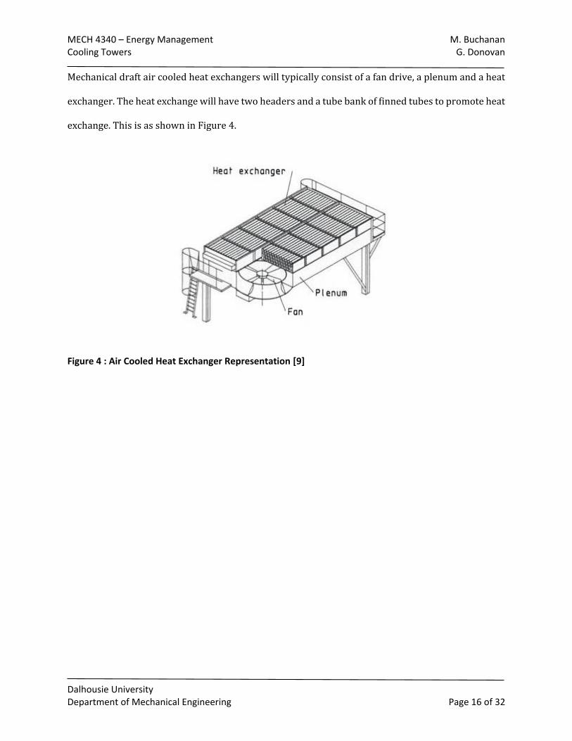
Mechanical draft air cooled heat exchangers will typically consist of a fan drive, a plenum and a heat
exchanger. The heat exchange will have two headers and a tube bank of finned tubes to promote heat
exchange. This is as shown in Figure 4.
Figure 4 : Air Cooled Heat Exchanger Representation [9]
MECH 4340 – Energy Management M. Buchanan Cooling Towers G. Donovan
Dalhousie University Department of Mechanical Engineering Page 17 of 32
4.1. Drive Systems
Drive systems are used to run different parts of the cooling towers. This can include drives used to
power the pumps required to circulate the water in wet cooling tower processes, or the motors used
to drive fans in forced draft mechanical cooling towers.
4.1.1. Motors
Motors are typically used to drive the fans that are part of the mechanical draft cooling tower
systems. Motors can also be used to power the pumps that are used to circulate water throughout
the wet cooling tower systems.
Electric motors function by using electromagnetism through a stator to rotate a rotor at a certain
speed. In industry, typically squirrel cage induction motors are used. These motors generally operate
at a consistent constant speed, and depending on what type of design of the motor resistance will
determine what sort of starting torque the motor has. These types of motors tend to have issues with
slip as the rotor will not spin at the exact synchronous speed. [10]
Motors that are used in cooling tower applications require a certain level of environmental protection
as they are often exposed to a lot of water either through process water or rain. The motor enclosure
used is a totally enclosed motor, which prevents the exchange of air between the inside and outside
of the motor. [10]
Motors used for fan drive applications without variable speed drives should be equipped with an
anti-rotation device to prevent wind milling of the fan blades. This is caused when a draft turns a
blade that is not in use. This effect can cause damage to the motors not equipped with variable speed
drives as when the motor is started up it is unable to overcome the backwards spin of the fan and
will fail. This leads to unnecessary replacement costs. The wind milling effect also poses a safety risk
MECH 4340 – Energy Management M. Buchanan Cooling Towers G. Donovan
Dalhousie University Department of Mechanical Engineering Page 18 of 32
to workers as the blades must be stopped before any maintenance can be performed. The anti-
rotation device is a simple one way clutch device that prevents the fan from the wind mill effect when
not in use. [3]
It is important to consider motor efficiency when purchasing motors as in the United States they
represent over half of all the energy consumption. The National Electrical Manufacturers association
have put forth standards of minimum standards and electric motor must meet to be considered
energy efficient. This is based off of the output a motor can output over the input requirements of the
motor, and are typically above 90% efficiency for motors larger than 10 HP. Energy efficient motors
represent large energy savings as upgrading a motor one percent can typically save approximately
$200 a year for a 50 HP motor. This can amount to a large sum of energy savings for industries that
require mass amounts of motors for operation. [11]
High efficiency motors are up to 10% more efficient than motors from 20 years ago. Increased
efficiency can enable more powerful motors to be placed into cooling tower applications where more
cooling capacity can be obtained without increasing power costs. [3]
4.1.2. Steam Turbines
Steam turbines may be used as an alternative to electric motors as drivers for pumps [12]. A steam
turbine uses the heat energy in steam to generate rotational power [13]. The type of turbine generally
used for mechanical drive is the impulse turbine. Rotational power is generated by redirecting the
steam into high speed jets using nozzles and diaphragms [13]. These jets impact blades mounted on
the rotor, causing it to rotate. During this process, the steam expands and is reduced in pressure. The
pressure differential created results in a net moment on the rotor that supplements the impact force
of the steam [13]. The number of sets of moving blades, or stages, varies for different turbines. More
MECH 4340 – Energy Management M. Buchanan Cooling Towers G. Donovan
Dalhousie University Department of Mechanical Engineering Page 19 of 32
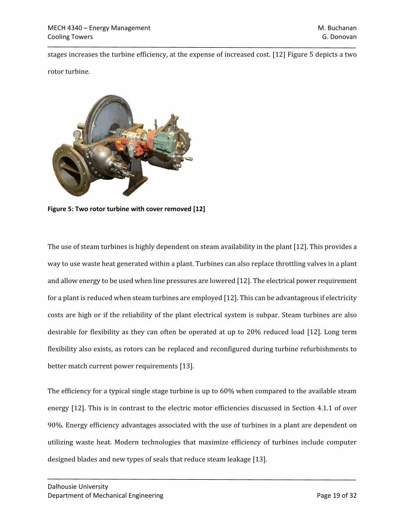
stages increases the turbine efficiency, at the expense of increased cost. [12] Figure 5 depicts a two
rotor turbine.
Figure 5: Two rotor turbine with cover removed [12]
The use of steam turbines is highly dependent on steam availability in the plant [12]. This provides a
way to use waste heat generated within a plant. Turbines can also replace throttling valves in a plant
and allow energy to be used when line pressures are lowered [12]. The electrical power requirement
for a plant is reduced when steam turbines are employed [12]. This can be advantageous if electricity
costs are high or if the reliability of the plant electrical system is subpar. Steam turbines are also
desirable for flexibility as they can often be operated at up to 20% reduced load [12]. Long term
flexibility also exists, as rotors can be replaced and reconfigured during turbine refurbishments to
better match current power requirements [13].
The efficiency for a typical single stage turbine is up to 60% when compared to the available steam
energy [12]. This is in contrast to the electric motor efficiencies discussed in Section 4.1.1 of over
90%. Energy efficiency advantages associated with the use of turbines in a plant are dependent on
utilizing waste heat. Modern technologies that maximize efficiency of turbines include computer
designed blades and new types of seals that reduce steam leakage [13].
MECH 4340 – Energy Management M. Buchanan Cooling Towers G. Donovan
Dalhousie University Department of Mechanical Engineering Page 20 of 32
4.2. Driven Systems
Driven systems in cooling towers are represented by the pumps used to move cooling fluids around,
or the fan drives used to create cooling in either induced or forced draft mechanical cooling towers.
These systems require either an electric motor or turbine unit to be driven.
4.2.1. Pumps
Pumps are required to circulate the cooling water through the plant piping network, heat exchangers,
and to elevate the water to the height of equipment and through the cooling tower itself [14]. The
initial water source is the basin at the bottom of the cooling tower, which will result in near or slightly
above atmospheric pressure at the pump suction. Pumps used in cooling towers are typically of the
centrifugal or axial flow variety [4].
Axial flow pumps are pumps that act like a propeller that is enclosed in a housing. The propeller
element, or impeller, creates a pressure change between the upstream and downstream flow of the
pump. Axial flow pumps are most suitable to deliver low head pressures and high flow rates. [15]
Axial pumps are subject to overloading issues when the pump flow is throttled below maximum
efficiency conditions, this should be accounted for with cooling tower applications and be considered
for any design implementations.
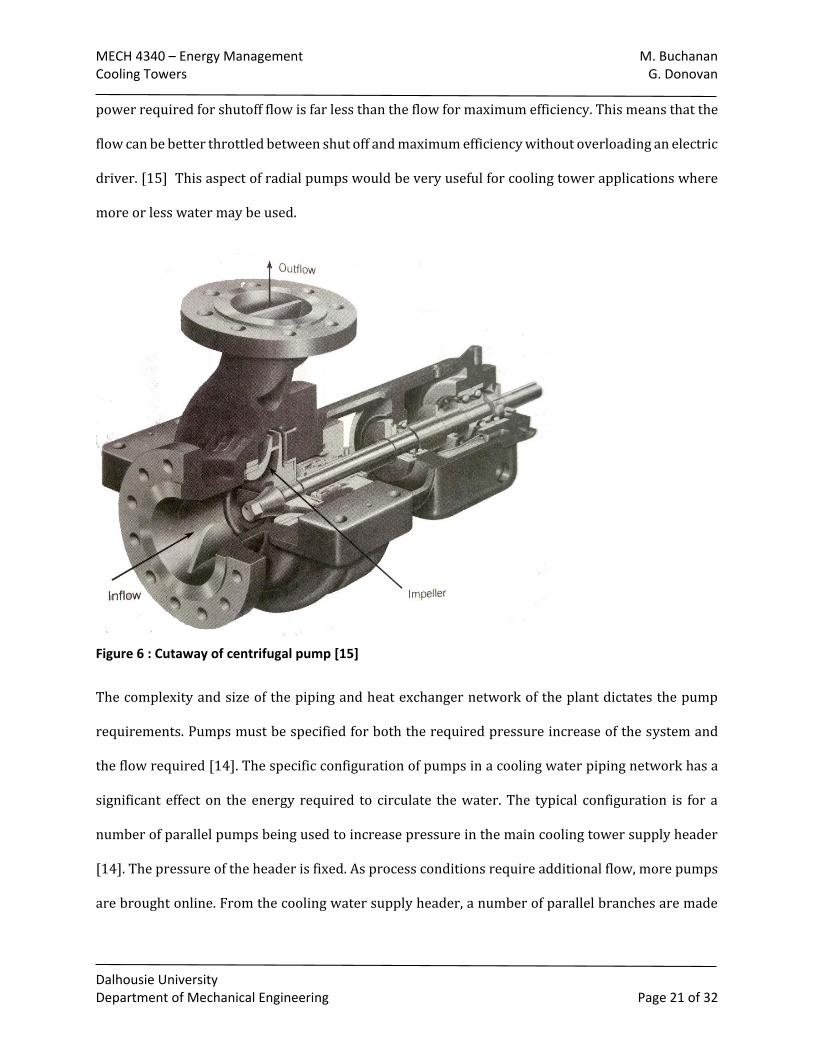
Centrifugal pumps are considered radial flow machines. They are considered better suited to larger
head pressures and lower flow rates than axial flow pumps. A centrifugal pump has fluid enter
through the eye of the impeller and will travel outwards from the impeller vanes to the edge where
it enters the pump case. From this point the fluid then travels through the case towards the discharge
pipe. A pressure increase due to the high velocity of flow from the over the impeller reducing to the
pump casing has the potential to cause internal failures if the system is not designed correctly. The
MECH 4340 – Energy Management M. Buchanan Cooling Towers G. Donovan
Dalhousie University Department of Mechanical Engineering Page 21 of 32
power required for shutoff flow is far less than the flow for maximum efficiency. This means that the
flow can be better throttled between shut off and maximum efficiency without overloading an electric
driver. [15] This aspect of radial pumps would be very useful for cooling tower applications where
more or less water may be used.
Figure 6 : Cutaway of centrifugal pump [15]
The complexity and size of the piping and heat exchanger network of the plant dictates the pump
requirements. Pumps must be specified for both the required pressure increase of the system and
the flow required [14]. The specific configuration of pumps in a cooling water piping network has a
significant effect on the energy required to circulate the water. The typical configuration is for a
number of parallel pumps being used to increase pressure in the main cooling tower supply header
[14]. The pressure of the header is fixed. As process conditions require additional flow, more pumps
are brought online. From the cooling water supply header, a number of parallel branches are made
MECH 4340 – Energy Management M. Buchanan Cooling Towers G. Donovan
Dalhousie University Department of Mechanical Engineering Page 22 of 32
to direct cooling water to heat exchangers. Once the cooling water has passed through the heat
exchanger, the water is routed to the main water return header [14].
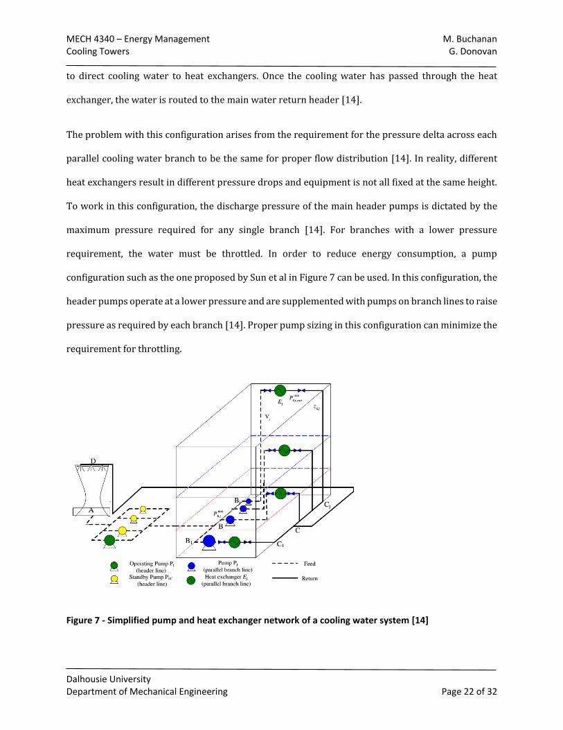
The problem with this configuration arises from the requirement for the pressure delta across each
parallel cooling water branch to be the same for proper flow distribution [14]. In reality, different
heat exchangers result in different pressure drops and equipment is not all fixed at the same height.
To work in this configuration, the discharge pressure of the main header pumps is dictated by the
maximum pressure required for any single branch [14]. For branches with a lower pressure
requirement, the water must be throttled. In order to reduce energy consumption, a pump
configuration such as the one proposed by Sun et al in Figure 7 can be used. In this configuration, the
header pumps operate at a lower pressure and are supplemented with pumps on branch lines to raise
pressure as required by each branch [14]. Proper pump sizing in this configuration can minimize the
requirement for throttling.
Figure 7 - Simplified pump and heat exchanger network of a cooling water system [14]
MECH 4340 – Energy Management M. Buchanan Cooling Towers G. Donovan
Dalhousie University Department of Mechanical Engineering Page 23 of 32
4.2.2. Fan Drives
Mechanical cooling towers can use fans to promote the flow of air to improve cooling efficiencies.
There are different types of fans that could be used to perform this. Fan blades can be constructed
from wood, plastic or metal. It is important to note that for cooling tower applications that blades
that are constructed from aluminum will not achieve their design rated airflow, due to inefficient
blade design. These blades which are typically straight-cord will only achieve 35% - 55% efficiency.
More modern fans which have better aerodynamic properties will have higher efficiencies, ranging
from 75% - 85% efficiency. [3]
This amount of increased air flow is desirable for air cooled heat exchangers, but will not be desirable
for wet cooling towers as more airflow can drag the cooling water stream too far into the tower.
Water in the tower can create corrosion of metal parts in both the driving equipment and the fixed,
and create non desirable working conditions for workers depending on the water quality. An airflow
increase of approximately 10% will allow a cooling duty increase of 5%-7% for condenser coolers,
3%-6% for liquid coolers and 2%-5% for vapor coolers, Blades can be constructed in such a way that
they can be noise reducing. [3]
The blades are connected to a central hub where they are attached with screws that allow the blades
to be adjustable. To run properly the blades need to be properly installed and aligned. Ways to
improve efficiencies of the fan blades include ensuring that the fan blades are pitched properly. This
is adjusting the blades to be set to ±0.5⁰ of each other, performing this will reduce vibration. [3]
Blades also must be installed in such a manner that the blades are spaced equally to reduce overall
fan vibration is reduced. Fan blades need to be adjusted in such a manner that the tip of the blade
offers enough clearance to run properly, but not have enough to promote air recirculation around
the tip. By either readjusting the blades, or adding a honeycomb aluminum seal fan performance can
MECH 4340 – Energy Management M. Buchanan Cooling Towers G. Donovan
Dalhousie University Department of Mechanical Engineering Page 24 of 32
be increased by up to 2%. [3] Fans will typically have a metal or plastic seal around the hub. If this
seal is missing or damaged it can decrease fan efficiency by causing recirculation. This seal disk
should typically be a quarter of the total fan diameter and if in place can increase fan efficiency by
2%. Air cooled heat exchanger applications can obtain a 3% efficiency increase by adding inlet bells
to the fan. [3]
Fans are either direct driven or driven by a belt system. Direct drive systems can only gain efficiencies
through the driver, while belt drives have different efficiency opportunities. There are two main
types of belts, v-belts and cog style. V-belts are a tapered belt that usually consists of a rubber jacket
and tension cord on the inside used to transmit power. V-belts generally use grooved pulleys as
sheaves and are usually grouped in sets to meet capacity. [17] V-belts slip more in the summer and
need to be re-tensioned throughout their lifetimes. [3] Cog belts are classified as cog style or timing
belts. The belts have teeth to aid with slippage and will use toothed sheaves. [17] Timing belts when
aligned and tensioned properly are considered 98% efficient and after re-tensioning shortly into
installation should not require and further maintenance in the life of the belt. The use of v-belts
should be minimized where possible as they increase bearing load of motors due to the tensioning
required for efficient running. If improper tensioning is used it will either lead to premature bearing
failures of the motors, or slippage which will require a shut down for the belt to be re-tensioned. [3]
MECH 4340 – Energy Management M. Buchanan Cooling Towers G. Donovan
Dalhousie University Department of Mechanical Engineering Page 25 of 32
4.3. Fixed Equipment
Equipment such as piping networks and heat exchangers are integral to cooling tower operation.
Given that cooling towers are often employed in refineries and other type of petrochemical plants,
the cooling capacity is generally distributed between a variety of processes [14]. Heat exchangers
allow the cooling tower water to exchange heat with other fluids.
The commonly used shell and tube heat exchanger consists of a series of tubes inside of a large
container. One fluid flows through the tubes and the other fluid flows in the container, over the
exterior of the tubes. Heat transfer takes place though the tube walls. A variety of sizes and
configurations for shell and tube heat exchangers exist, depending on the amount of cooling required
and fluid properties. [18]
Air cooled heat exchangers use a tube bank heat exchanger to cool the fluid. These tube bank bundles
consist of a nozzle and return header which entrain a system of finned tubes. These finned tubes can
be constructed of extruded fins, embedded fins or footed fins. Footed fins are the cheapest option as
they are constructed and welded to the outside of the tubes in the exchanger. These fins are not overly
effective in staying attached to the tubes over time and will lose cooling efficiency. Embedded fins are
fins that are integrated into the tube bank. These fins are disadvantageous because they require
thicker tube walls to be implemented. Extruded fins offer the most reliability as they are a solid piece
of fin. The efficiency of these fins should not degrade over time. Extruded fins are best suited for
corrosive environments because of this. If any of the fins on the tube bank are damaged, which could
include bent or missing, it will affect the thermal capabilities of the heat exchanger. This damage will
decrease the overall cooling capacity of the tube bank. Damage can also occur due to inadequate
thermal restraint from the headers. This occurs from rapid cooling of the fluid without any restraint,
bending the tubes and distorting their forms. This will also decrease thermal efficiency [18]
MECH 4340 – Energy Management M. Buchanan Cooling Towers G. Donovan
Dalhousie University Department of Mechanical Engineering Page 26 of 32
The tube banks present in air cooled heat exchangers are often subject to fouling around the fin area.
This fouling can be attributed to dirt and debris build up from the process area, or corrosion from
weather. This debris can completely coat the fins and reduce their cooling capabilities to a minimum.
Often, to return to the original cooling capabilities of the exchanger it is necessary to clean all of the
debris from the fins. [3]
When integrated into a plant, a cooling tower will interface with what may be a complex piping
network in order to distribute the cooling water and return it to the cooling tower. This piping
network will interface with any heat exchangers or pumps in the system. [14]
Corrosion is a general concern for piping networks, but for cooling towers the primary challenge with
fixed equipment is microbial growth [18]. Microbial growth can be in the form of algae, bacteria, or
fungi and can have a variety of negative effects on cooling tower equipment. The cooling water is
conductive to microbial growth due to high oxygen content and the concentrating effect of
evaporative cooling [18]. Additionally, the presence of stagnant water anywhere in the system
encourages growth [18].
Process water entering a cooling tower will contain some amount of microbes and other dissolved
material. As water evaporates in the cooling tower, the dissolved and suspended material remain in
the cooling circuit. [18]
Corrosion and fouling are the two primary mechanisms by which microbes affect cooling tower
equipment, though other damage mechanisms exist such as accelerated rotting of wood structures
[18]. The corrosion is a result of the presence of microbes such as certain bacteria that have the ability
to break down the metal, typically carbon steel, which makes up the pipe wall [19]. A biofilm will
form that covers these microbes and provides protection from the water flow [19]. Fouling is a term
used to describe a reduction in heat exchanger performance as a result of a contaminated heat
MECH 4340 – Energy Management M. Buchanan Cooling Towers G. Donovan
Dalhousie University Department of Mechanical Engineering Page 27 of 32
transfer surface [17]. As the inner or outer surface of the tubes in a shell and tube heat exchanger
become covered with a biofilm, the resistance to heat transfer increases. This has a negative effect on
the heat exchanger efficiency and additional cooling water flow would be required to cool a given
amount of process fluid.
If the cooling water was released to the environment when the microbes were of high concentration,
this would be a form of pollution as many of these microbes can cause human harm. As an example,
the bacteria that cause legionaries disease are often found in cooling water systems [18]. A variety of
other methods are employed to manage the microbes present in cooling towers. Biocides are
chemicals such as chlorine and ozone that are capable of killing the microbes. The use of biocides is
being reduced due to environmental concerns [18] [19].
Bio dispersants are substances that prevent microbes from attaching to and biofilms from forming
on equipment without killing the microbes [18]. Increasing the use of plastics can reduce corrosion
concerns. Heat exchanger fouling can be managed through the introduction of sponge balls to the
cooling water steam when tube side. These balls are forced through the tubes of the heat exchanger
and physically wipe the biofilm away [19]. This can be done when equipment is online, using a
strainer to recover the balls. Similarly, brushes can be used that are integrated into the heat
exchanger and can be slid back and forth inside the tubes by reversing flow [19]. An additional
method is to use flexible tubes in the heat exchanger. These tubes vibrate with the flow to prevent
the formation of biofilms [19]. Basic changes to cooling tower operation can also reduce the impact
of microbes. Since stagnant water encourages the growth of biofilms, stagnant water should be
avoided wherever possible. This includes minimizing basin and sump levels and recirculating or
draining the water when the cooling tower is shut down or on standby. Configuring heat exchangers
so that cooling water is present on the tube side also reduces cooling water exposure to stagnant
flow. [19]
MECH 4340 – Energy Management M. Buchanan Cooling Towers G. Donovan
Dalhousie University Department of Mechanical Engineering Page 28 of 32
5. Summary
Cooling Towers, both wet and dry are used in different applications worldwide for cooling purposes.
These applications include power plants, oil refineries, chemical plants and even building cooling.
Cooling towers are used to reject heat from industrial and commercial processes as required. This is
performed by transferring heat from a cooling fluid, typically water, but occasionally air or another
fluid by means of an interfacial film. This heat is then transferred from the film to air by typical heat
transfer, or evaporative methods. [1] The amount of heat transferred from the cooing fluid must be
equal to that of the heat absorbed by the air flowing through the tower. This heat transfer can be
difficult in colder temperatures as the water used in wet cooling towers can freeze when the flow of
water through the cooling tower systems is unequal. [2]
The towers can be natural of mechanical draft. This is the difference of allow natural airflow through
the tower or mechanically inducing airflow through the tower. There are different types of
mechanical draft coolers. There are induced and forced draft coolers which indicate how the airflow
is drawn over the cooler. Induced draft coolers use a fan at the exit of a cooler to create airflow. Forced
draft coolers use a fan at the inlet of the cooler to force airflow through the cooler. [4]
These towers can also have different airflow through. The coolers can either have a counter or cross
flow airflow in the cooler. A counter flow cooling tower has airflow in the vertical direction to the
main flow of fluid needing to be cooled. A cross flow cooling tower has airflow in the horizontal
direction to the main flow of fluid needing to be cooled. Cross flow cooling towers can also be
considered either single or double flow towers. A single flow tower consists of only a single inlet,
while double flow will have two inlets. [4]
MECH 4340 – Energy Management M. Buchanan Cooling Towers G. Donovan
Dalhousie University Department of Mechanical Engineering Page 29 of 32
Cooling towers can either be wet or air cooled as well. Water used in wet cooling towers can have
issues of fouling due to the hardness of the water often used. Water in cooling towers are often
treated with corrosion and biological growth inhibitors, meaning that this mineral buildup tends to
have the highest effect on water losses of the towers, by requiring either a water treatment plant to
be put in place or more makeup water to be added to the systems. Water cooled systems will use less
overall energy than air cooled heat exchangers, and there are many energy efficiency gains that can
be attributed for both systems from more efficient technologies. [8]
Air cooled heat exchangers will have a higher capital cost than a water cooling tower alternative, the
cost to provide water to the wet system along with increased maintenance costs can make the dry
system have a lower lifetime running cost. Depending on the availability of water it may be more
desirable to implement a dry system to conserve water [9]
The components of the cooling towers are readily broken down into fixed equipment, drive
equipment and driven equipment. The fixed equipment consists of the piping network used to
transport the water and the tube banks used in air cooled heat exchangers as other heat exchangers.
Drive equipment can be either electric motors or turbines and driven equipment consists of fan
drives and pumps used to transport either cooling or cooled fluids.
One of the biggest threats to fixed equipment is microbial contamination. This can result in
accelerated corrosion of piping components as well as the fouling of heat exchangers [18]. Typical
methods to manage microbes in cooling water have traditionally been biocides such as chlorine, but
more environmentally friendly methods such as bio dispersants and the use of alternative materials
and operation techniques are increasingly employed to reduce the impact of these organisms. [19]
Motors are typically used to drive the fans that are part of the mechanical draft cooling tower
systems. Motors can also be used to power the pumps that are used to circulate water throughout
MECH 4340 – Energy Management M. Buchanan Cooling Towers G. Donovan
Dalhousie University Department of Mechanical Engineering Page 30 of 32
the wet cooling tower systems. It is important to consider motor efficiency when purchasing motors
as in the United States they represent over half of all the energy consumption. The National Electrical
Manufacturers association have standards that determine the minimum requirements for a motor to
be considered energy efficient. These motors are typically above 90% efficiency for motors larger
than 10 HP. Energy efficient motors represent large energy savings as upgrading a motor one percent
can typically save approximately $200 a year for a 50 HP motor. [11]
As an alternative to electric motors, turbines may also be used as drivers for pumps used in cooling
tower systems [13]. Although less efficient when directly compared to electric motors, turbines can
be used to harness waste heat generated in neighbouring processes and are more flexible in
operation than electric motors [12].
Modern fans which have better aerodynamic properties will have higher efficiencies, ranging from
75% - 85% efficiency. An airflow increase of approximately 10% will allow a cooling duty increase of
5%-7% for condenser coolers, 3%-6% for liquid coolers and 2%-5% for vapor coolers. [3]
Fan blade efficiency can be improved by ensuring that the fan blades are pitched to ±0.5⁰ of each
other, performing this will reduce vibration. [3] Fan blades need to be adjusted in such a manner that
the tip of the blade offers enough clearance to run properly, but not have enough to promote air
recirculation around the tip a snug fit will increase fan performance can by up to 2%. [3] Proper
installation of a good condition fan hub will increase fan efficiency by 2%. Air cooled heat exchanger
applications can obtain a 3% efficiency increase by adding inlet bells to the fan. [3]
Fans are either direct driven or driven by a belt system. Direct drive systems can only gain efficiencies
through the driver, while belt drives have different efficiency opportunities. Timing belts when
aligned and tensioned properly are considered 98% efficient and after re-tensioning shortly into
installation should not require and further maintenance in the life of the belt. The use of v-belts
MECH 4340 – Energy Management M. Buchanan Cooling Towers G. Donovan
Dalhousie University Department of Mechanical Engineering Page 31 of 32
should be minimized where possible as they increase bearing load of motors due to the tensioning
required for efficient running. If improper tensioning is used it will either lead to premature bearing
failures of the motors, or slippage which will require a shut down for the belt to be re-tensioned. [3]
Pumps are essential to the operation of a cooling tower, as the water is a motive fluid that requires
energy input in order to be distributed throughout the network of piping and plant equipment.
Centrifugal and axial flow pumps are typically employed, depending on pressure and flow
requirements [4]. Networks of pumps in parallel and series are constructed in order to allow the
system to handle varying demand in pressure and flow according to plant operation. The flexibility
and configuration of this network is important for overall energy usage and to minimize the use of
throttling devices [14].
MECH 4340 – Energy Management M. Buchanan Cooling Towers G. Donovan
Dalhousie University Department of Mechanical Engineering Page 32 of 32
References
[1] R. Rosaler, Standard Handbook of Plant Engineering, New York: McGRAW-HILL, 2002.
[2] P. Lindahl, "Cold Weather Operation Cooling Towers," ASHRAE, pp. 26-37, 2014.
[3] N. Agius, "Optimize air-cooled heat exchanger performance," Hydrocarbon Processing, pp. 89-94, 2006.
[4] K. McKelvey and M. Brooke, The Industrial Cooling Tower, New York: Elsevier Publishing Company, 1959.
[5] J. Hensley, Cooling Tower Fundamentals, Kansas: The Marley Cooling Tower Company, 1985.
[6] M. Goodarzi and R. Ramezanpour, "Alternative geometry for cylindrical natural draft cooling tower with higher cooling efficiency under crosswind conditions," Energy Conversion and Management, vol. 77, pp. 243-249, 2014.
[7] C. Cremaschi and X. Wu, "Effect of Fouling on the Thermal Performance of Condensers and on the Water Consumption in Cooling Tower Systems," Heat Transfer Engineering, vol. 36, no. 7-8, 2013.
[8] F. Morrison, "Saving Energy With Cooling Towers," ASHRAE, pp. 34-40, 2014.
[9] D. Kroger, Air-cooled Heat Exchangers and Cooling Towers, Oklahoma: PenWell, 2004.
[10] F. Petruzella, Electric Motors and Control Systems, New York: McGraw Hill, 2010.
[11] US Department of Energy, "Buying an Energy-Efficient Electric Motor," [Online]. Available: https://www1.eere.energy.gov/manufacturing/tech_assistance/pdfs/mc-0382.pdf. [Accessed 24 January 2015].
[12] M. A. Cerce and V. P. Patel, "Selecting Steam Turbines for Pump Drives," 2003. [Online]. Available: http://turbolab.tamu.edu/proc/pumpproc/P20/12.pdf. [Accessed 10 February 2015].
[13] H. P. Bloch and M. P. Singh, Steam Turbines: Design, Applications, and Rerating, vol. II, McGraw-Hill, 2009.
[14] K. H. Chu, C. Deng, Y. Wang, X. Feng and J. Sun, "Pump network optimization for a cooling water system," Energy, vol. 67, pp. 506-512, 2014.
[15] C. Crowe, D. Elger, B. Williams and J. Roberson, Engineering Fluid Mechanics, John Wiley and Sons, 2009.
[16] R. Juvinall and K. Marshek, Fundamentals of Machine Component Design, 2006.
[17] F. Incropera, D. Dewitt, T. Bergman and A. Lavine, Funamentals of Heat and Mass Transfer, John Wiley and Sons, 2205.
[18] S. G. Choudhary, "Emerging microbial control issues in cooling water systems," Hydrocarbon Processing, vol. 77, no. 5, pp. 91-103, May 1998.
[19] T. R. Bott, "Techniques for reducing the amount of biocide necessary to counteract the effects of biofilm growth in cooling water systems," Applied Thermal Engineering, vol. 18, pp. 1059-1066, 1998.