Embed Size (px)
Citation preview
04/10 506510−01
�������� ����������Page 1
�2010 Lennox Industries Inc.Dallas, Texas, USA
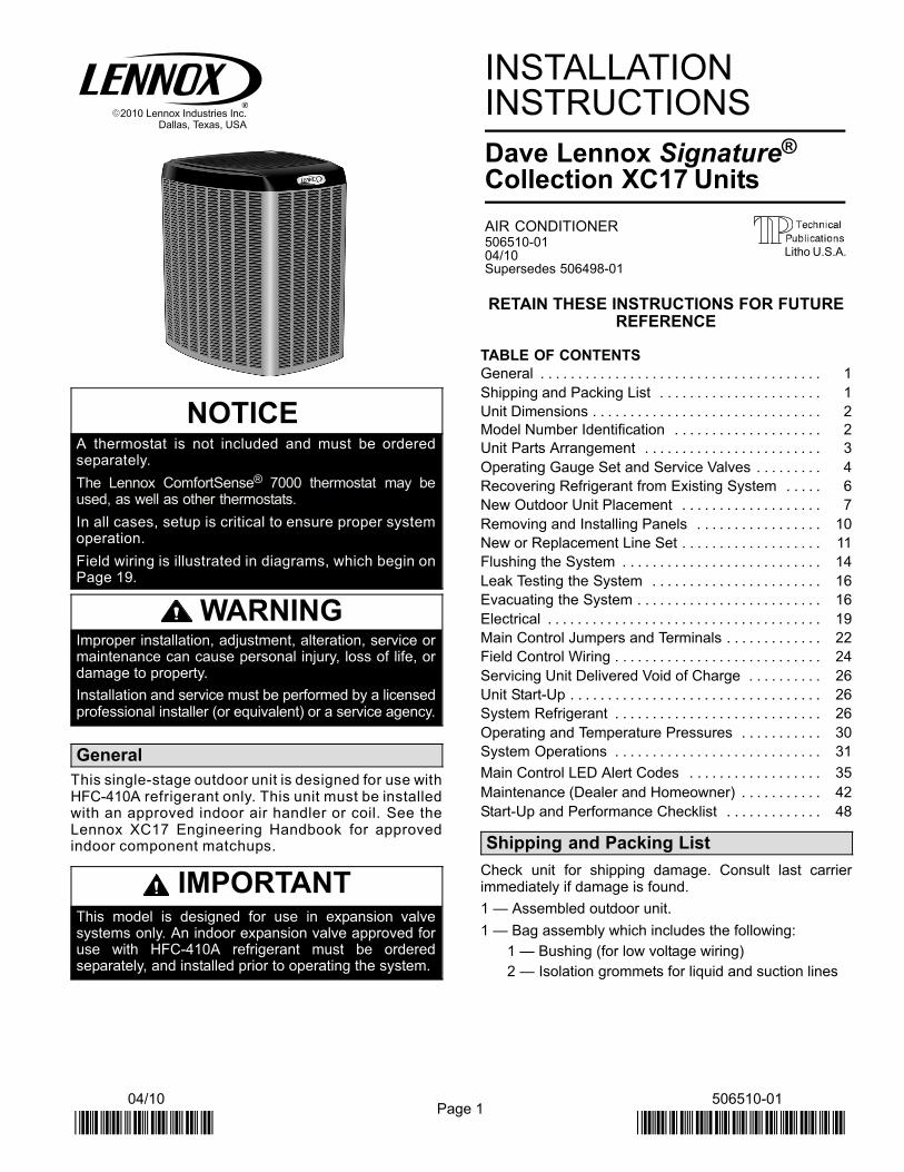
NOTICEA thermostat is not included and must be orderedseparately.
The Lennox ComfortSense® 7000 thermostat may beused, as well as other thermostats.
In all cases, setup is critical to ensure proper systemoperation.
Field wiring is illustrated in diagrams, which begin onPage 19.
WARNINGImproper installation, adjustment, alteration, service ormaintenance can cause personal injury, loss of life, ordamage to property.
Installation and service must be performed by a licensedprofessional installer (or equivalent) or a service agency.
General
This single−stage outdoor unit is designed for use withHFC−410A refrigerant only. This unit must be installedwith an approved indoor air handler or coil. See theLennox XC17 Engineering Handbook for approvedindoor component matchups.
IMPORTANTThis model is designed for use in expansion valvesystems only. An indoor expansion valve approved foruse with HFC−410A refrigerant must be orderedseparately, and installed prior to operating the system.
INSTALLATIONINSTRUCTIONS
Dave Lennox Signature®
Collection XC17 Units
AIR CONDITIONER506510−01 04/10Supersedes 506498−01
RETAIN THESE INSTRUCTIONS FOR FUTUREREFERENCE
TABLE OF CONTENTS
General 1. . . . . . . . . . . . . . . . . . . . . . . . . . . . . . . . . . . . . .
Shipping and Packing List 1. . . . . . . . . . . . . . . . . . . . . .
Unit Dimensions 2. . . . . . . . . . . . . . . . . . . . . . . . . . . . . . .
Model Number Identification 2. . . . . . . . . . . . . . . . . . . .
Unit Parts Arrangement 3. . . . . . . . . . . . . . . . . . . . . . . .
Operating Gauge Set and Service Valves 4. . . . . . . . .
Recovering Refrigerant from Existing System 6. . . . .
New Outdoor Unit Placement 7. . . . . . . . . . . . . . . . . . .
Removing and Installing Panels 10. . . . . . . . . . . . . . . . .
New or Replacement Line Set 11. . . . . . . . . . . . . . . . . . .
Flushing the System 14. . . . . . . . . . . . . . . . . . . . . . . . . . .
Leak Testing the System 16. . . . . . . . . . . . . . . . . . . . . . .
Evacuating the System 16. . . . . . . . . . . . . . . . . . . . . . . . .
Electrical 19. . . . . . . . . . . . . . . . . . . . . . . . . . . . . . . . . . . . .
Main Control Jumpers and Terminals 22. . . . . . . . . . . . .
Field Control Wiring 24. . . . . . . . . . . . . . . . . . . . . . . . . . . .
Servicing Unit Delivered Void of Charge 26. . . . . . . . . .
Unit Start−Up 26. . . . . . . . . . . . . . . . . . . . . . . . . . . . . . . . . .
System Refrigerant 26. . . . . . . . . . . . . . . . . . . . . . . . . . . .
Operating and Temperature Pressures 30. . . . . . . . . . .
System Operations 31. . . . . . . . . . . . . . . . . . . . . . . . . . . .
Main Control LED Alert Codes 35. . . . . . . . . . . . . . . . . .
Maintenance (Dealer and Homeowner) 42. . . . . . . . . . .
Start−Up and Performance Checklist 48. . . . . . . . . . . . .
Shipping and Packing List
Check unit for shipping damage. Consult last carrierimmediately if damage is found.
1 � Assembled outdoor unit.
1 � Bag assembly which includes the following:
1 � Bushing (for low voltage wiring)
2 � Isolation grommets for liquid and suction lines
Litho U.S.A.

Page 2
506510−01
Unit Dimensions − Inches (mm) and Parts Arrangement
4−5/8(117)
39.40"(1003) 35.50"
(902)
18.60"(470)
8.00" (203)
1 (25)
LIQUIDLINEINLET
SUCTION LINEINLET
ELECTRICAL INLETS
BASE WITH ELONGATED LEGS
SIDE VIEW ACCESS VIEW
DISCHARGE AIR
[−024] 41 (1040)
[−030 THROUGH−060] 47 (1194)
16−7/8(429)
8−3/4(222)
26−7/8(683)
3−3/4 (95)
30−3/4(781)
3−1/8(79)
UNIT SUPPORTFEET
Model Number Identification
C 17 036− −
Unit TypeC = Air Conditioner
Series
Nominal Cooling Capacity024 = 2 tons 030 = 2.5 tons036 = 3 tons 042 = 3.5 tons048 = 4 tons 060 = 5 tons
Minor Revision Number
230
Voltage230 = 208/230V−1ph−60hz
Refrigerant TypeX = R−410A
X 2−
Page 3
XC17 SERIES
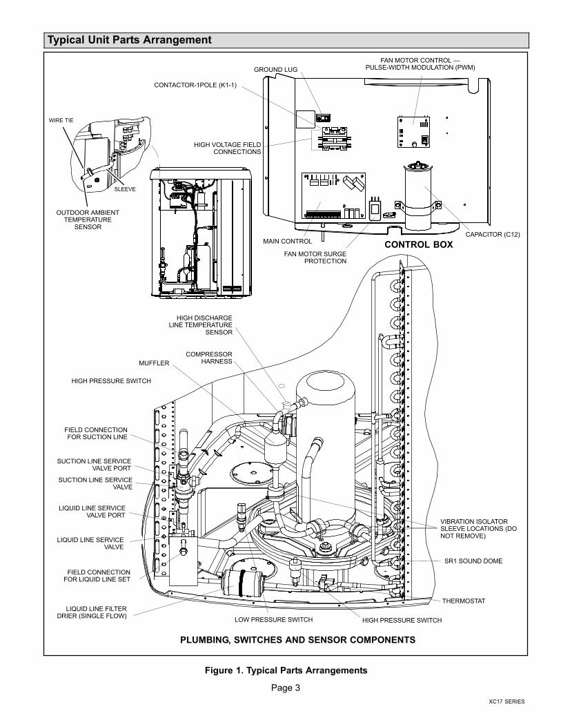
Typical Unit Parts Arrangement
LIQUID LINE FILTERDRIER (SINGLE FLOW)
HIGH PRESSURE SWITCH
FIELD CONNECTIONFOR LIQUID LINE SET
LIQUID LINE SERVICEVALVE
LIQUID LINE SERVICEVALVE PORT
SUCTION LINE SERVICEVALVE PORT
SUCTION LINE SERVICEVALVE
FIELD CONNECTIONFOR SUCTION LINE
MUFFLER
HIGH DISCHARGELINE TEMPERATURE
SENSOR
LOW PRESSURE SWITCH HIGH PRESSURE SWITCH
THERMOSTAT
COMPRESSORHARNESS
SR1 SOUND DOME
VIBRATION ISOLATORSLEEVE LOCATIONS (DONOT REMOVE)
GROUND LUG
HIGH VOLTAGE FIELDCONNECTIONS
CONTACTOR−1POLE (K1−1)
MAIN CONTROLCAPACITOR (C12)
CONTROL BOX
PLUMBING, SWITCHES AND SENSOR COMPONENTS
SLEEVE
WIRE TIE
OUTDOOR AMBIENTTEMPERATURE
SENSOR
FAN MOTOR CONTROL �PULSE−WIDTH MODULATION (PWM)
FAN MOTOR SURGEPROTECTION
Figure 1. Typical Parts Arrangements

Page 4
506510−01
CAUTIONPhysical contact with metal edges and corners whileapplying excessive force or rapid motion can result inpersonal injury. Be aware of, and use caution whenworking near these areas during installation or whileservicing this equipment.
IMPORTANTThe Clean Air Act of 1990 bans the intentional venting ofrefrigerant (CFCs, HCFCs AND HFCs) as of July 1,1992. Approved methods of recovery, recycling orreclaiming must be followed. Fines and/or incarcerationmay be levied for noncompliance.
IMPORTANTThis unit must be matched with an indoor coil asspecified in Lennox’ Engineering Handbook. Coilspreviously charged with HCFC−22 must be flushed.
WARNINGElectric Shock Hazard. Can cause injuryor death. Unit must be grounded inaccordance with national and localcodes.
Line voltage is present at all componentswhen unit is not in operation on units withsingle-pole contactors. Disconnect allremote electric power supplies beforeopening access panel. Unit may havemultiple power supplies.
Operating Gauge Set and Service Valves
These instructions are intended as a general guide and donot supersede local codes in any way. Consult authoritieswho have jurisdiction before installation.
TORQUE REQUIREMENTS
When servicing or repairing heating, ventilating, and airconditioning components, ensure the fasteners areappropriately tightened. Table 1 lists torque values forfasteners.
IMPORTANTOnly use Allen wrenches of sufficient hardness (50Rc −Rockwell Harness Scale minimum). Fully insert thewrench into the valve stem recess.
Service valve stems are factory−torqued (from 9 ft−lbs forsmall valves, to 25 ft−lbs for large valves) to preventrefrigerant loss during shipping and handling. Using anAllen wrench rated at less than 50Rc risks rounding orbreaking off the wrench, or stripping the valve stemrecess.
See the Lennox Service and Application Notes #C−08−1for further details and information.
IMPORTANTTo prevent stripping of the various caps used, theappropriately sized wrench should be used and fittedsnugly over the cap before tightening.
Table 1. Torque Requirements
Parts Recommended Torque
Service valve cap 8 ft.− lb. 11 NM
Sheet metal screws 16 in.− lb. 2 NM
Machine screws #10 28 in.− lb. 3 NM
Compressor bolts 90 in.− lb. 10 NM
Gauge port seal cap 8 ft.− lb. 11 NM
USING MANIFOLD GAUGE SET
When checking the system charge, only use a manifoldgauge set that features low loss anti−blow back fittings.
Manifold gauge set used with HFC−410A refrigerantsystems must be capable of handling the higher systemoperating pressures. The gauges should be rated for usewith pressures of 0 − 800 psig on the high side and a lowside of 30" vacuum to 250 psig with dampened speed to500 psi. Gauge hoses must be rated for use at up to 800psig of pressure with a 4000 psig burst rating.
OPERATING SERVICE VALVES
The liquid and vapor line service valves are used forremoving refrigerant, flushing, leak testing, evacuating,checking charge and charging.
Each valve is equipped with a service port which has afactory−installed valve stem. Figure 2 provides informationon how to access and operating both angle and ball servicevalves.

Page 5
XC17 SERIES
(VALVE STEM SHOWNCLOSED) INSERT HEXWRENCH HERE
VALVE STEMFRONT-SEATED
TO OUTDOORUNIT
SERVICE PORTCORE
TO INDOORUNIT
SERVICE PORT
SERVICE PORT CAP
CLOSED TO BOTHINDOOR AND OUTDOOR
UNITS
STEM CAP
ANGLE−TYPESERVICE VALVE(FRONT−SEATED
CLOSED)
SERVICE PORTSERVICE PORT
CORE
TO OUTDOOR UNIT
STEM CAP
(VALVE STEMSHOWN OPEN)INSERT HEXWRENCH HERE
SERVICE PORT CAP
TO INDOORUNIT
OPEN TO BOTH INDOOR ANDOUTDOOR UNITS
ANGLE−TYPE SERVICE VALVE(BACK−SEATED OPENED)
BALL (SHOWN CLOSED)
SERVICE PORT CORE
TO INDOOR UNIT
TO OUTDOOR UNIT
TO OPEN ROTATE STEMCOUNTERCLOCKWISE 90°.
TO CLOSE ROTATE STEMCLOCKWISE 90°.
SERVICE PORT
SERVICE PORT CAP
STEM CAP
VALVE STEM
WHEN SERVICE VALVE IS CLOSED, THE SERVICE PORT IS OPEN TO THELINE SET AND INDOOR UNIT.
BALL−TYPE SERVICEVALVE
SERVICE VALVESVARIOUS TYPES
WHEN SERVICE VALVE IS OPEN, THE SERVICE PORT IS OPEN TO LINE SET,INDOOR AND OUTDOOR UNIT.
To Access Service Port:
A service port cap protects the service port core from contamination andserves as the primary leak seal.
1. Remove service port cap with an appropriately sized wrench.
2. Connect gauge set to service port.
3. When testing is completed, replace service port cap and tighten as fol-lows: 1
23
4567
8910
11 12
1/6 TURN
Operating Angle Type Service Valve:
1. Remove stem cap with an appropriately sized wrench.
2. Use a service wrench with a hex−head extension (3/16" for liquid line valve sizes and 5/16" for vapor line valvesizes) to back the stem out counterclockwise as far as it will go.
Operating Ball Type Service Valve:
1. Remove stem cap with an appropriately sized wrench.
2. Use an appropriately sized wrenched to open. To open valve, rotate stem counterclockwise 90°. To close rotate stem clockwise 90°.
Reinstall Stem Cap:
Stem cap protects the valve stem from damage and serves as the primary seal. Replace the stem cap andtighten as follows:
� With Torque Wrench: Finger tighten and then torque cap per Table 1.
� Without Torque Wrench: Finger tighten and use an appropriately sized wrench to turn
an additional 1/12 turn clockwise.
NOTE � A label with specific torque requirements may be affixed to the stem cap. If the label is present, use the specified torque.
123
4567
8910
11 12
1/6 TURN
� With Torque Wrench: Finger tighten and torque cap per Table 1.
� Without Torque Wrench: Finger tighten and use an appropriately
sized wrench to turn an additional 1/6 turn clockwise.
Figure 2. Angle and Ball Service Valves
Page 6
506510−01
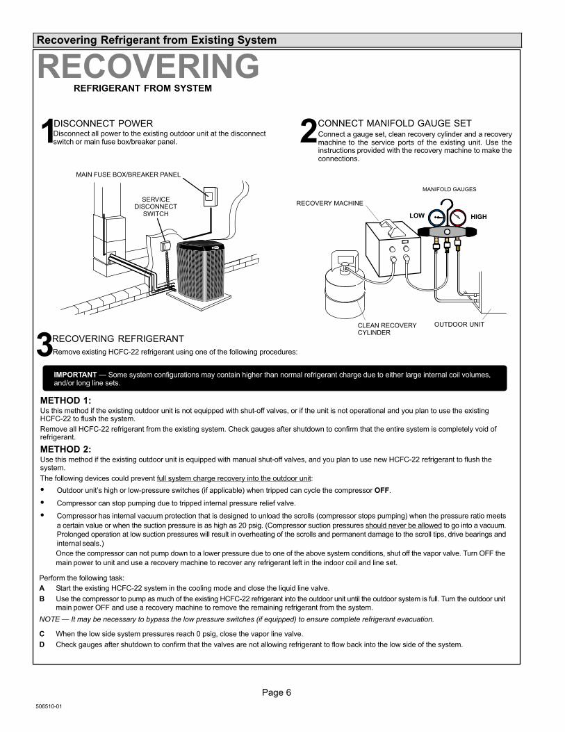
Recovering Refrigerant from Existing System
SERVICEDISCONNECT
SWITCH
MAIN FUSE BOX/BREAKER PANEL
Disconnect all power to the existing outdoor unit at the disconnectswitch or main fuse box/breaker panel.
DISCONNECT POWER CONNECT MANIFOLD GAUGE SET
MANIFOLD GAUGES
RECOVERY MACHINE
CLEAN RECOVERYCYLINDER
OUTDOOR UNIT
HIGHLOW
Connect a gauge set, clean recovery cylinder and a recoverymachine to the service ports of the existing unit. Use theinstructions provided with the recovery machine to make theconnections.
METHOD 1:Us this method if the existing outdoor unit is not equipped with shut−off valves, or if the unit is not operational and you plan to use the existingHCFC−22 to flush the system.
Remove all HCFC−22 refrigerant from the existing system. Check gauges after shutdown to confirm that the entire system is completely void ofrefrigerant.
METHOD 2:Use this method if the existing outdoor unit is equipped with manual shut−off valves, and you plan to use new HCFC−22 refrigerant to flush thesystem.
The following devices could prevent full system charge recovery into the outdoor unit:
� Outdoor unit’s high or low−pressure switches (if applicable) when tripped can cycle the compressor OFF.
� Compressor can stop pumping due to tripped internal pressure relief valve.
� Compressor has internal vacuum protection that is designed to unload the scrolls (compressor stops pumping) when the pressure ratio meets
a certain value or when the suction pressure is as high as 20 psig. (Compressor suction pressures should never be allowed to go into a vacuum.
Prolonged operation at low suction pressures will result in overheating of the scrolls and permanent damage to the scroll tips, drive bearings and
internal seals.)
Once the compressor can not pump down to a lower pressure due to one of the above system conditions, shut off the vapor valve. Turn OFF the
main power to unit and use a recovery machine to recover any refrigerant left in the indoor coil and line set.
Perform the following task:
A Start the existing HCFC−22 system in the cooling mode and close the liquid line valve.
B Use the compressor to pump as much of the existing HCFC−22 refrigerant into the outdoor unit until the outdoor system is full. Turn the outdoor unitmain power OFF and use a recovery machine to remove the remaining refrigerant from the system.
NOTE � It may be necessary to bypass the low pressure switches (if equipped) to ensure complete refrigerant evacuation.
C When the low side system pressures reach 0 psig, close the vapor line valve.
D Check gauges after shutdown to confirm that the valves are not allowing refrigerant to flow back into the low side of the system.
RECOVERINGREFRIGERANT FROM SYSTEM
Remove existing HCFC−22 refrigerant using one of the following procedures:
RECOVERING REFRIGERANT
IMPORTANT � Some system configurations may contain higher than normal refrigerant charge due to either large internal coil volumes,and/or long line sets.
1 2
3

Page 7
XC17 SERIES
CONTROL PANELACCESS
LOCATION
6 (152)
36 (914)
12 (305)30 (762)
LINE SETCONNECTIONS
24 (610)
LINE SETCONNECTIONS
ACCESS PANEL
REAR VIEW OF UNIT
48 (1219)
MINIMUM CLEARANCE BETWEENTWO UNITS
CLEARANCE ON ALL SIDES � INCHES (MILLIMETERS)
ACCESS PANEL
MINIMUM CLEARANCEABOVE UNIT
NOTES:
� Clearance to one of the other three
sides must be 36 inches (914mm).
� Clearance to one of the remaining
two sides may be 12 inches(305mm) and the final side may be6 inches (152mm).
Figure 3. Installation Clearances
New Outdoor Unit Placement
CAUTIONIn order to avoid injury, take proper precaution whenlifting heavy objects.
See Unit Dimensions on page 3 for sizing mounting slab,platforms or supports. Refer to Figure 3 for mandatoryinstallation clearance requirements.
POSITIONING CONSIDERATIONS
Consider the following when positioning the unit:
� Some localities are adopting sound ordinances based
on the unit’s sound level registered from the adjacent
property, not from the installation property. Install theunit as far as possible from the property line.
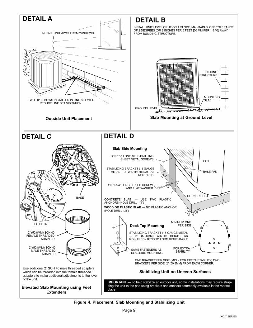
� When possible, do not install the unit directly outside
a window. Glass has a very high level of soundtransmission. For proper placement of unit in relation
to a window see the provided illustration in Figure 4,Detail A.
PLACING UNIT ON SLAB
When installing unit at grade level, the top of the slabshould be high enough above grade so that water fromhigher ground will not collect around the unit. The slabshould have a slope tolerance as described in Figure 4,Detail B.
NOTE � If necessary for stability, anchor unit to slab as
described in Figure 4, Detail D.

Page 8
506510−01
ELEVATING THE UNIT
Units are outfitted with elongated support feet as illustratedin Figure 4, Detail C.
If additional elevation is necessary, raise the unit byextending the height of the unit support feet. This may beachieved by using a 2 inch (50.8mm) Schedule 40 femalethreaded adapter.
The specified coupling will fit snuggly into the recessedportion of the feet. Use additional 2 inch (50.8mm)Schedule 40 male threaded adaptors which can bethreaded into the female threaded adaptors to makeadditional adjustments to the level of the unit.
NOTE � Keep the height of extenders short enough to
ensure a sturdy installation. If it is necessary to extend
further, consider a different type of field−fabricated
framework that is sturdy enough for greater heights.
STABILIZING UNIT ON UNEVEN SURFACES
IMPORTANTUnit Stabilizer Bracket Use (field−provided):
Always use stabilizers when unit is raised above thefactory height. (Elevated units could become unstable ingusty wind conditions).
Stabilizers may be used on factory height units whenmounted on unstable an uneven surface.
With unit positioned at installation site, perform the
following:1. Remove two side louvered panels to expose the unit
base.
2. Install the brackets as illustrated in Figure 4, Detail Dusing conventional practices.
3. Replace the panels after installation is complete.
ROOF MOUNTING
Install the unit a minimum of 6 inches (152 mm) above theroof surface to avoid ice build−up around the unit. Locatethe unit above a load bearing wall or area of the roof thatcan adequately support the unit. Consult local codes forrooftop applications.
If unit coil cannot be mounted away from prevailing winterwinds, a wind barrier should be constructed. Size barrier atleast the same height and width as outdoor unit. Mountbarrier 24 inches (610 mm) from the sides of the unit in thedirection of prevailing winds.
NOTICERoof Damage!
This system contains both refrigerant and oil. Somerubber roofing material may absorb oil and cause therubber to swell when it comes into contact with oil. Therubber will then bubble and could cause leaks. Protectthe roof surface to avoid exposure to refrigerant and oilduring service and installation. Failure to follow thisnotice could result in damage to roof surface.
Page 9
XC17 SERIES
LEG DETAIL
BASE
2" (50.8MM) SCH 40FEMALE THREADED
ADAPTER
ONE BRACKET PER SIDE (MIN.); FOR EXTRA STABILITY, TWOBRACKETS PER SIDE, 2" (50.8MM) FROM EACH CORNER.
CONCRETE SLAB � USE TWO PLASTICANCHORS (HOLE DRILL 1/4")
COIL
BASE PAN
CORNER POST
STABILIZING BRACKET (18 GAUGEMETAL � 2" WIDTH; HEIGHT AS
REQUIRED)
Slab Side Mounting
#10 1/2" LONG SELF−DRILLINGSHEET METAL SCREWS
#10 1−1/4" LONG HEX HD SCREWAND FLAT WASHER
MINIMUM ONEPER SIDE
STABILIZING BRACKET (18 GAUGE METAL� 2" (50.8MM) WIDTH; HEIGHT ASREQUIRED); BEND TO FORM RIGHT ANGLE
FOR EXTRASTABILITY
Deck Top Mounting
Elevated Slab Mounting using FeetExtenders
Stabilizing Unit on Uneven Surfaces
WOOD OR PLASTIC SLAB � NO PLASTIC ANCHOR(HOLE DRILL 1/8")
TWO 90° ELBOWS INSTALLED IN LINE SET WILLREDUCE LINE SET VIBRATION.
INSTALL UNIT LEVEL OR, IF ON A SLOPE, MAINTAIN SLOPE TOLERANCEOF 2 DEGREES (OR 2 INCHES PER 5 FEET [50 MM PER 1.5 M]) AWAYFROM BUILDING STRUCTURE.
MOUNTINGSLAB
BUILDINGSTRUCTURE
GROUND LEVEL
Outside Unit Placement Slab Mounting at Ground Level
INSTALL UNIT AWAY FROM WINDOWS
SAME FASTENERS ASSLAB SIDE MOUNTING.
IMPORTANT � To help stabilize an outdoor unit, some installations may require strap-ping the unit to the pad using brackets and anchors commonly available in the market-place.
DETAIL A DETAIL B
DETAIL C DETAIL D
2" (50.8MM) SCH 40MALE THREADED
ADAPTER
Use additional 2" SCH 40 male threaded adapterswhich can be threaded into the female threadedadapters to make additional adjustments to the levelof the unit.
Figure 4. Placement, Slab Mounting and Stabilizing Unit

Page 10
506510−01
Removing and Installing Panels
REMOVE 4 SCREWS TOREMOVE PANEL FORACCESSING COMPRESSORAND CONTROLS.
POSITION PANEL WITH HOLESALIGNED; INSTALL SCREWSAND TIGHTEN.
ACCESS PANEL REMOVALRemoval and reinstallation of the accesspanel is as illustrated.
Detail A
Detail C
Detail B
ROTATE IN THIS DIRECTION; THENDOWN TO REMOVE PANEL
SCREWHOLES
LIP
PANEL SHOWN SLIGHTLY ROTATED TO ALLOW TOP TAB TO EXIT (OR ENTER) TOP SLOTFOR REMOVING (OR INSTALLING) PANEL.
MAINTAIN MINIMUM PANEL ANGLE (AS CLOSE TO PARALLELWITH THE UNIT AS POSSIBLE) WHILE INSTALLING PANEL.
PREFERREDANGLE FORINSTALLATION
Detail D
ANGLE MAY BETOO EXTREME
HOLD DOOR FIRMLY ALONG THEHINGED SIDE TO MAINTAINFULLY−ENGAGED TABS
LOUVERED PANEL REMOVALRemove the louvered panels as follows:
1. Remove two screws, allowing the panel to swing open slightly.
2. Hold the panel firmly throughout this procedure. Rotate bottom corner of panelaway from hinged corner post until lower three tabs clear the slots as illustrated inDetail B.
3. Move panel down until lip of upper tab clears the top slot in corner post as illustratedin Detail A.
LOUVERED PANEL INSTALLATION
Position the panel almost parallel with the unit as illustrated in Detail D with the screw
side as close to the unit as possible. Then, in a continuous motion:
1. Slightly rotate and guide the lip of top tab inward as illustrated in Detail A and C;then upward into the top slot of the hinge corner post.
2. Rotate panel to vertical to fully engage all tabs.
3. Holding the panel’s hinged side firmly in place, close the right−hand side of the pan-el, aligning the screw holes.
4. When panel is correctly positioned and aligned, insert the screws and tighten.
PANELSACCESS AND LOUVERED
IMPORTANT � Do not allow panels to hang on unit by top tab. Tab is for align-ment and not designed to support weight of panel.
IMPORTANT � To help stabilize an outdoor unit, some installations may requirestrapping the unit to the pad using brackets and anchors commonly available in themarketplace.
To prevent personal injury, or damage to panels, unit or structure, be sure to observethe following:
While installing or servicing this unit, carefully stow all removed panels out of theway, so that the panels will not cause injury to personnel, nor cause damage to ob-jects or structures nearby, nor will the panels be subjected to damage (e.g., beingbent or scratched).
While handling or stowing the panels, consider any weather conditions, especiallywindy conditions, that may cause panels to be blown around and battered.
WARNING

Page 11
XC17 SERIES
New or Replacement Line Set
REFRIGERANT LINE SET
This section provides information on installation orreplacement of existing line set. If new or replacement lineset is not being installed then proceed to BrazingConnections on page 13.
IMPORTANTLennox highly recommends changing line set whenconverting the existing system from HCFC−22 toHFC−410A. If that is not possible and the line set is theproper size as reference in Table 2, use the procedureoutlined under Flushing the System on page 13.
If refrigerant lines are routed through a wall, then seal andisolate the opening so vibration is not transmitted to thebuilding. Pay close attention to line set isolation duringinstallation of any HVAC system. When properly isolatedfrom building structures (walls, ceilings. floors), therefrigerant lines will not create unnecessary vibration andsubsequent sounds. See Figure 5 for recommendedinstallation practices. Also, consider the following whenplacing and installing a high−efficiency outdoor unit.
Liquid lines that meter the refrigerant, such as RFC1 liquidlines, must not be used in this application. Existing line setof proper size as listed in Table 2 may be reused. If systemwas previously charged with HCFC−22 refrigerant, thenexisting line set must be flushed (see Flushing the Systemon page 14).
Field refrigerant piping consists of liquid and vapor linesfrom the outdoor unit to the indoor unit coil (brazeconnections). Use Lennox L15 (sweat, non−flare) seriesline set, or field−fabricated refrigerant line sizes as listed inTable 2.
Table 2. Refrigerant Line Set � Inches (mm)
Model
Size
FieldConnections
Recommended Line Set
LiquidLine
VaporLine
LiquidLine
VaporLine
L15Line Sets
Feet (Meters)
−0243/8�(10)
3/4�(19)
3/8�(10)
3/4�(19)
L15−4115 − 50’ (5 − 15)
−030
−0363/8�(10)
7/8�(22)
3/8�(10)
7/8�(22)
L15−6515 − 50’ (5 − 15)−042
3/8�(10)
7/8�(22)
3/8�(10)
7/8�(22)
−048
−0603/8�(10)
1−1/8�.(29)
3/8�(10)
1−1/8�(29) Field Fabricated
NOTE � Some applications may required a field provided 7/8" to1−1/8" adapter
NOTE � When installing refrigerant lines longer than 50
feet, see the Lennox Refrigerant Piping Design and
Fabrication Guidelines, CORP. 9351−L9, or contact
Lennox Technical Support Product Applications for
assistance.
IMPORTANTMineral oils are not compatible with HFC−410A. If oilmust be added, it must be a Polyol ester oil.
The compressor is charged with sufficient Polyol ester oilfor line set lengths up to 50 feet. If line set lengths longerthan 50 feet will be required, all one (1) ounce of oil forevery additional 10 feet of line set. Do not add any morethan seven (7) ounces of oil.
Recommended topping−off POE oils are Mobil EALARCTIC 22 CC or ICI EMKARATE� RL32CF.
To obtain the correct information from Lennox, be sure tocommunicate the following information:
� Model (XC17) and size of unit (e.g. −036).
� Line set diameters for the unit being installed as listed
in Table 2 and total length of installation.
� Number of elbows vertical rise or drop in the piping.
WARNINGDanger of fire. Bleeding the refrigerantcharge from only the high side may resultin the low side shell and suction tubingbeing pressurized. Application of abrazing torch while pressurized mayresult in ignition of the refrigerant and oilmixture − check the high and lowpressures before unbrazing.
WARNINGWhen using a high pressure gas such asdry nitrogen to pressurize a refrigerationor air conditioning system, use aregulator that can control the pressuredown to 1 or 2 psig (6.9 to 13.8 kPa).
CAUTIONBrazing alloys and flux contain materials which arehazardous to your health.
Avoid breathing vapors or fumes from brazingoperations. Perform operations only in well ventilatedareas.
Wear gloves and protective goggles or face shield toprotect against burns.
Wash hands with soap and water after handling brazingalloys and flux.
Page 12
506510−01
ANCHORED HEAVY NYLONWIRE TIE OR AUTOMOTIVE
MUFFLER-TYPE HANGER
STRAP LIQUID LINE TOVAPOR LINE
WALLSTUD
LIQUID LINE
NON−CORROSIVEMETAL SLEEVE
VAPOR LINE − WRAPPEDIN ARMAFLEX
AUTOMOTIVEMUFFLER-TYPE HANGER
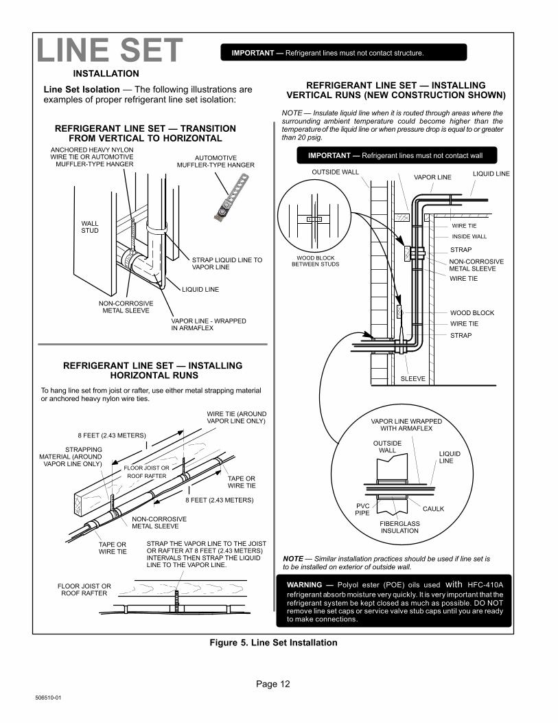
REFRIGERANT LINE SET � TRANSITIONFROM VERTICAL TO HORIZONTAL
Line Set Isolation � The following illustrations areexamples of proper refrigerant line set isolation:
STRAPPINGMATERIAL (AROUND
VAPOR LINE ONLY)
TAPE ORWIRE TIE
WIRE TIE (AROUNDVAPOR LINE ONLY)
FLOOR JOIST ORROOF RAFTER
TAPE ORWIRE TIE
To hang line set from joist or rafter, use either metal strapping materialor anchored heavy nylon wire ties.
8 FEET (2.43 METERS)
STRAP THE VAPOR LINE TO THE JOISTOR RAFTER AT 8 FEET (2.43 METERS)INTERVALS THEN STRAP THE LIQUIDLINE TO THE VAPOR LINE.
FLOOR JOIST OR
ROOF RAFTER
REFRIGERANT LINE SET � INSTALLING HORIZONTAL RUNS
NOTE � Similar installation practices should be used if line set isto be installed on exterior of outside wall.
PVCPIPE
FIBERGLASSINSULATION
CAULK
OUTSIDEWALL
VAPOR LINE WRAPPEDWITH ARMAFLEX
LIQUIDLINE
OUTSIDE WALL LIQUID LINEVAPOR LINE
WOOD BLOCKBETWEEN STUDS
STRAP
WOOD BLOCK
STRAP
SLEEVE
WIRE TIE
WIRE TIE
WIRE TIE
INSIDE WALL
REFRIGERANT LINE SET � INSTALLINGVERTICAL RUNS (NEW CONSTRUCTION SHOWN)
INSTALLATION
LINE SET
NOTE � Insulate liquid line when it is routed through areas where thesurrounding ambient temperature could become higher than thetemperature of the liquid line or when pressure drop is equal to or greaterthan 20 psig.
NON−CORROSIVEMETAL SLEEVE
IMPORTANT � Refrigerant lines must not contact structure.
NON−CORROSIVEMETAL SLEEVE
8 FEET (2.43 METERS)
IMPORTANT � Refrigerant lines must not contact wall
WARNING � Polyol ester (POE) oils used with HFC−410A
refrigerant absorb moisture very quickly. It is very important that therefrigerant system be kept closed as much as possible. DO NOTremove line set caps or service valve stub caps until you are readyto make connections.
Figure 5. Line Set Installation
Page 13
XC17 SERIES
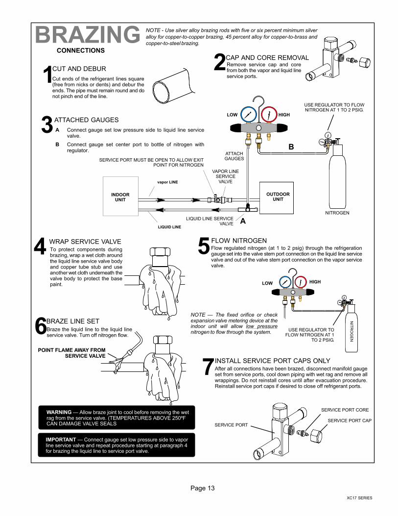
CUT AND DEBUR
CAP AND CORE REMOVAL
Cut ends of the refrigerant lines square(free from nicks or dents) and debur theends. The pipe must remain round and donot pinch end of the line.
Remove service cap and corefrom both the vapor and liquid lineservice ports.
ATTACHED GAUGES
OUTDOORUNIT
LIQUID LINE
vapor LINE
LIQUID LINE SERVICEVALVE
VAPOR LINESERVICE
VALVE
ATTACHGAUGES
INDOORUNIT
SERVICE PORT MUST BE OPEN TO ALLOW EXITPOINT FOR NITROGEN
A Connect gauge set low pressure side to liquid line servicevalve.
B Connect gauge set center port to bottle of nitrogen withregulator.
NITROGEN
HIGHLOW
USE REGULATOR TO FLOWNITROGEN AT 1 TO 2 PSIG.
WRAP SERVICE VALVE FLOW NITROGEN
To protect components duringbrazing, wrap a wet cloth aroundthe liquid line service valve bodyand copper tube stub and useanother wet cloth underneath thevalve body to protect the basepaint.
Flow regulated nitrogen (at 1 to 2 psig) through the refrigerationgauge set into the valve stem port connection on the liquid line servicevalve and out of the valve stem port connection on the vapor servicevalve.
NOTE � The fixed orifice or checkexpansion valve metering device at theindoor unit will allow low pressurenitrogen to flow through the system.
NIT
RO
GE
N
HIGHLOW
USE REGULATOR TOFLOW NITROGEN AT 1
TO 2 PSIG.
BRAZE LINE SET
INSTALL SERVICE PORT CAPS ONLY
Braze the liquid line to the liquid lineservice valve. Turn off nitrogen flow.
After all connections have been brazed, disconnect manifold gaugeset from service ports, cool down piping with wet rag and remove allwrappings. Do not reinstall cores until after evacuation procedure.Reinstall service port caps if desired to close off refrigerant ports.
IMPORTANT � Connect gauge set low pressure side to vaporline service valve and repeat procedure starting at paragraph 4for brazing the liquid line to service port valve.
SERVICE PORT CORE
SERVICE PORT CAPSERVICE PORT
WARNING � Allow braze joint to cool before removing the wetrag from the service valve. (TEMPERATURES ABOVE 250ºFCAN DAMAGE VALVE SEALS
CONNECTIONS
BRAZING
12
3
4 5
6
7
B
A
POINT FLAME AWAY FROMSERVICE VALVE
NOTE − Use silver alloy brazing rods with five or six percent minimum silver
alloy for copper−to−copper brazing, 45 percent alloy for copper−to−brass and
copper−to−steel brazing.

Page 14
506510−01
Flushing the System
SENSINGLINE
TEFLON RING
FIXED ORIFICE
(Uncased Coil Shown)
BRASS NUT
LIQUID LINE ASSEMBLY(INCLUDES STRAINER)
LIQUID LINE ORIFICE HOUSING
DISTRIBUTOR TUBES
DISTRIBUTORASSEMBLY
REMOVE AND DISCARDWHITE TEFLON SEAL (IF
PRESENT)
A On fully cased coils, remove the coil access and plumbing panels.
B Remove any shipping clamps holding the liquid line and distributorassembly.
C Using two wrenches, disconnect liquid line from liquid line orificehousing. Take care not to twist or damage distributor tubes duringthis process.
D Remove and discard fixed orifice, valve stem assembly if presentand Teflon washer as illustrated above.
E Use a field−provided fitting to temporary reconnect the liquid line tothe indoor unit’s liquid line orifice housing.
TYPICAL FIXED ORIFICE REMOVAL PROCEDURE
TYPICAL CHECK EXPANSION VALVEREMOVAL PROCEDURE
TWO PIECE PATCH PLATE(UNCASED COIL ONLY)
VAPORLINE
DISTRIBUTORASSEMBLY
DISTRIBUTORTUBES
LIQUIDLINE
MALE EQUALIZERLINE FITTING
EQUALIZERLINE
CHECKEXPANSION
VALVE
TEFLONRING
(Uncased Coil Shown)STUB END
TEFLONRING
SENSING BULB
LIQUID LINEORIFICE
HOUSING
LIQUID LINEASSEMBLY WITH
BRASS NUT
A On fully cased coils, remove the coil access and plumbing panels.
B Remove any shipping clamps holding the liquid line and distributor as-sembly.
C Disconnect the equalizer line from the check expansion valve equaliz-er line fitting on the vapor line.
D Remove the vapor line sensing bulb.
E Disconnect the liquid line from the check expansion valve at the liquidline assembly.
F Disconnect the check expansion valve from the liquid line orifice hous-ing. Take care not to twist or damage distributor tubes during this pro-cess.
G Remove and discard check expansion valve and the two Teflon rings.
H Use a field−provided fitting to temporary reconnect the liquid line to theindoor unit’s liquid line orifice housing.
LOW HIGH
EXISTINGINDOOR unit
GAUGEMANIFOLD
INVERTED HCFC−22CYLINDER CONTAINSCLEAN HCFC−22 TO BEUSED FOR FLUSHING.
LIQUID LINE SERVICEVALVE
INLET
DISCHARGE
TANKRETURN
CLOSEDOPENED
RECOVERYCYLINDER
RECOVERY MACHINE
NEWOUTDOOR
UNIT
VAPOR LINESERVICE VALVE
VA
PO
R
LIQ
UID
1
A Inverted HCFC−22 cylinder with clean refrigerant to the vapor servicevalve.
B HCFC−22 gauge set (low side) to the liquid line valve.
C HCFC−22 gauge set center port to inlet on the recovery machine withan empty recovery tank to the gauge set.
D Connect recovery tank to recovery machines per machineinstructions.
CONNECT GAUGES AND EQUIPMENT FORFLUSHING PROCEDURE
A
B
CD
B
OR
FLUSHING LINE SET
A Set the recovery machine for liquid recovery and start the recov-ery machine. Open the gauge set valves to allow the recoverymachine to pull a vacuum on the existing system line set and in-door unit coil.
B Invert the cylinder of clean HCFC−22 and open its valve to allowliquid refrigerant to flow into the system through the vapor linevalve. Allow the refrigerant to pass from the cylinder and throughthe line set and the indoor unit coil before it enters the recoverymachine.
C After all of the liquid refrigerant has been recovered, switch therecovery machine to vapor recovery so that all of the HCFC−22vapor is recovered. Allow the recovery machine to pull down to 0the system.
D Close the valve on the inverted HCFC−22 drum and the gaugeset valves. Pump the remaining refrigerant out of the recoverymachine and turn the machine off.
The line set and indoor unit coil must be flushed with at least thesame amount of clean refrigerant that previously charged the sys-tem. Check the charge in the flushing cylinder before proceeding.
LINE SET AND INDOOR COIL (1 OF 2)
FLUSHING
1
2
3
CAUTION � This procedure should not be performed on sys-tems which contain contaminants (Example compressor burnout.

Page 15
XC17 SERIES
A Attach the vapor line sensing bulb in the proper orientationas illustrated to the right using the clamp and screws pro-vided.
NOTE � Confirm proper thermal contact between vapor line
and check expansion bulb before insulating the sensing bulb
once installed.
B Connect the equalizer line from thecheck expansion valve to theequalizer vapor port on the vaporline. Finger tighten the flare nutplus 1/8 turn (7 ft−lbs) as illus-trated below.
The check expansion valve unit can be installed internal orexternal to the indoor coil. In applications where an uncased coilis being installed in a field−provided plenum, install the checkexpansion valve in a manner that will provide access for fieldservicing of the check expansion valve. Refer to belowillustration for reference during installation of check expansionvalve unit.
TYPICAL CHECK EXPANSION VALVE INSTALLATION PROCEDURE
TWO PIECEPATCH PLATE
(UNCASEDCOIL ONLY)
VAPORLINE
LIQUID LINEORIFICE
HOUSINGDISTRIBUTOR
TUBES
LIQUID LINE
MALE EQUALIZER LINEFITTING (SEE
EQUALIZER LINEINSTALLATION FORFURTHER DETAILS)
SENSINGLINE
EQUALIZERLINE
CHECKEXPANSION
VALVE
TEFLONRING
(Uncased Coil Shown)
SENSING BULB INSULATION IS REQUIREDIF MOUNTED EXTERNAL TO THE COILCASING. SENSING BULB INSTALLATIONFOR BULB POSITIONING.
STUBEND
TEFLONRING
LIQUID LINEASSEMBLY WITH
BRASS NUT
DISTRIBUTORASSEMBLY
This outdoor unit is designed for use in systems that use check expansion valve metering device. See the Lennox XC17 Engineering Handbookfor approved check expansion valve kit match−ups and application information.
A Remove the field−provided fitting that temporary reconnected the liquidline to the indoor unit’s distributor assembly.
B Install one of the provided Teflon rings around the stubbed end of thecheck expansion valve and lightly lubricate the connector threads andexpose surface of the Teflon ring with refrigerant oil.
C Attach the stubbed end of the check expansion valve to the liquid lineorifice housing. Finger tighten and use an appropriately sized wrench toturn an additional 1/2 turn clockwise as illustrated in the figure above, or20 ft−lb.
D Place the remaining Teflon washer around the other end of the checkexpansion valve. Lightly lubricate connector threads and expose sur-face of the Teflon ring with refrigerant oil.
E Attach the liquid line assembly to the check expansion valve. Fingertighten and use an appropriately sized wrench to turn an additional 1/2turn clockwise as illustrated in the figure above or 20 ft−lb.
ON 7/8" AND LARGER LINES,MOUNT SENSING BULB ATEITHER THE 4 OR 8 O’CLOCKPOSITION. NEVER MOUNT ONBOTTOM OF LINE.
12
ON LINES SMALLER THAN 7/8",MOUNT SENSING BULB ATEITHER THE 3 OR 9 O’CLOCKPOSITION.
12
BULB
VAPOR LINE
VAPOR LINE
NOTE � NEVER MOUNT ON BOTTOM OF LINE.
BULB
BULBBULB
VAPOR LINE
FLARE NUT
COPPER FLARESEAL BONNET
MALE BRASS EQUALIZERLINE FITTING
FLARE SEAL CAP
OR
123
4567
8910
11 12 1/2 TURN
SENSING BULB INSTALLATION
EQUALIZER LINE INSTALLATION
123
45
678
910
11 12
1/8 TURN
FLUSHING LINE SET AND INDOOR COIL (2 OF 2)
4
A Remove and discard either the flare seal cap or flare nutwith copper flare seal bonnet from the equalizer line porton the vapor line as illustrated in the figure to the right.
B Remove and discard either the flare seal cap or flare nutwith copper flare seal bonnet from the equalizer line port onthe vapor line as illustrated in the figure to the right.

Page 16
506510−01
INSTALLING ISOLATION GROMMETS
Locate the isolation grommets (provided). Slide grommetsonto vapor and liquid lines. Insert grommets into pipingpanel to isolate refrigerant lines from sheet metal edges.
TWO ISOLATION GROMMETS AREPROVIDE FOR THE LIQUID ANDSUCTION LINE PIPE PANEL PASSTHROUGH.
LIQUID LINE
SUCTION LINE
REAR VIEW OF UNIT EXTERIOR
PIPING PANEL
Figure 6. Isolation Grommets
IMPORTANTThe Environmental Protection Agency (EPA) prohibitsthe intentional venting of HFC refrigerants duringmaintenance, service, repair and disposal of appliance.Approved methods of recovery, recycling or reclaimingmust be followed.
IMPORTANTIf this unit is being matched with an approved line setor indoor unit coil which was previously charged withmineral oil, or if it is being matched with a coil whichwas manufactured before January of 1999, the coiland line set must be flushed prior to installation. Takecare to empty all existing traps. Polyol ester (POE) oilsare used in Lennox units charged with HFC−410Arefrigerant. Residual mineral oil can act as aninsulator, preventing proper heat transfer. It can alsoclog the expansion device, and reduce the systemperformance and capacity.Failure to properly flush the system per theinstructions below will void the warranty.
Leak Testing the System
WARNINGWhen using a high pressure gas such asdry nitrogen to pressurize a refrigerationor air conditioning system, use aregulator that can control the pressuredown to 1 or 2 psig (6.9 to 13.8 kPa).
IMPORTANTLeak detector must be capable of sensing HFCrefrigerant.
WARNINGRefrigerant can be harmful if it is inhaled. Refrigerantmust be used and recovered responsibly.
Failure to follow this warning may result in personal injuryor death.
WARNINGFire, Explosion and Personal SafetyHazard.
Failure to follow this warning couldresult in damage, personal injury ordeath.
Never use oxygen to pressurize orpurge refrigeration lines. Oxygen,when exposed to a spark or openflame, can cause damage by fireand/or an explosion, that could resultin personal injury or death.

Page 17
XC17 SERIES
TO VAPORSERVICE VALVE
HFC−410A
MANIFOLD GAUGE SET
OUTDOOR UNIT
HIGHLOW
NITROGEN
NOTE � Normally, the high pressure hose is connected to the liquid line port. How-
ever, connecting it to the vapor port better protects the manifold gauge set from high
pressure damage.
A With both manifold valves closed, connect the cylinder of HFC−410A refrigerant to the center port of the manifold gauge set. Openthe valve on the HFC−410A cylinder (vapor only).
B Open the high pressure side of the manifold to allow HFC−410A into the line set and indoor unit. Weigh in a trace amount ofHFC−410A. [A trace amount is a maximum of two ounces (57 g) refrigerant or three pounds (31 kPa) pressure]. Close the valve onthe HFC−410A cylinder and the valve on the high pressure side of the manifold gauge set. Disconnect the HFC−410A cylinder.
C Connect a cylinder of dry nitrogen with a pressure regulating valve to the center port of the manifold gauge set.
D Adjust dry nitrogen pressure to 150 psig (1034 kPa). Open the valve on the high side of the manifold gauge set in order to pressurize theline set and the indoor unit.
E After a few minutes, open one of the service valve ports and verify that the refrigerant added to the system earlier is measurablewith a leak detector.
F After leak testing disconnect gauges from service ports.
LINE SET AND INDOOR COIL
After the line set has been connected to the indoor unit and air conditioner, check the line set connections andindoor unit for leaks. Use the following procedure to test for leaks:
LEAK TEST
A Connect an HFC−410A manifold gauge set highpressure hose to the vapor valve service port.
B With both manifold valves closed, connect thecylinder of HFC−410A refrigerant to the center portof the manifold gauge set.
1CONNECT GAUGE SET
2TEST FOR LEAKS
AB
NOTE � Later in the procedure, the HFC−410Acontainer will be replaced by the nitrogen container.
LIQUID LINESERVICE VALVE
VAPOR SERVICE VALVE

Page 18
506510−01
Evacuating the System
A Open both manifold valves and start the vacuum pump.
B Evacuate the line set and indoor unit to an absolute pressure of 23,000 microns (29.01 inches of mercury).
NOTE � During the early stages of evacuation, it is desirable to close the manifold gauge valve at least once. A rapid rise in pressure
indicates a relatively large leak. If this occurs, repeat the leak testing procedure.
NOTE � The term absolute pressure means the total actual pressure within a given volume or system, above the absolute zero of
pressure. Absolute pressure in a vacuum is equal to atmospheric pressure minus vacuum pressure.
C When the absolute pressure reaches 23,000 microns (29.01 inches of mercury), close the manifold gauge valves, turn off the vacuumpump and disconnect the manifold gauge center port hose from vacuum pump. Attach the manifold center port hose to a dry nitrogencylinder with pressure regulator set to 150 psig (1034 kPa) and purge the hose. Open the manifold gauge valves to break the vacuum inthe line set and indoor unit. Close the manifold gauge valves.
D Shut off the dry nitrogen cylinder and remove the manifold gauge hose from the cylinder. Open the manifold gauge valves to release thedry nitrogen from the line set and indoor unit.
E Reconnect the manifold gauge to the vacuum pump, turn the pump on, and continue to evacuate the line set and indoor unit until theabsolute pressure does not rise above 500 microns (29.9 inches of mercury) within a 20−minute period after shutting off the vacuum pumpand closing the manifold gauge valves.
F When the absolute pressure requirement above has been met, disconnect the manifold hose from the vacuum pump and connect it to anupright cylinder of HFC−410A refrigerant. Open the manifold gauge valve 1 to 2 psig in order to release the vacuum in the line set andindoor unit.
G Perform the following:
OUTDOOR
UNIT
TO VAPORSERVICE VALVE
TO LIQUID LINESERVICE VALVE
MICRONGAUGE
VACUUM PUMP
A34000 1/4 SAE TEE WITHSWIVEL COUPLER
500
MANIFOLDGAUGE SET
HFC−410A
RECOMMENDMINIMUM 3/8" HOSE
A Connect low side of manifold gauge setwith 1/4 SAE in−line tee to vapor lineservice valve
B Connect high side of manifold gaugeset to liquid line service valve
C Connect micron gauge availableconnector on the 1/4 SAE in−line tee.
D Connect the vacuum pump (withvacuum gauge) to the center port of themanifold gauge set. The center port linewill be used later for both the HFC−410Aand nitrogen containers.
HIGHLOW
123
45
678
910
11 12
1/6 TURN
NITROGEN
EVACUATING
1CONNECT GAUGE SET
A
B
C
D
2EVACUATE THE SYSTEM
� Close manifold gauge valves.
� Shut off HFC−410A cylinder.
� Reinstall service valve cores by removing manifold hose from service valve. Quickly install cores with
core tool while maintaining a positive system pressure.
� Replace the stem caps and secure finger tight, then tighten an additional one−sixth (1/6) of a turn as
illustrated.
LINE SET AND INDOOR COIL
NOTE � Remove cores from service valves (if not al-
ready done).
LIQUID LINESERVICE VALVE
VAPORSERVICE
VALVE

Page 19
XC17 SERIES
IMPORTANTUse a thermocouple or thermistor electronic vacuumgauge that is calibrated in microns. Use an instrumentcapable of accurately measuring down to 50 microns.
WARNINGDanger of Equipment Damage. Avoid deep vacuumoperation. Do not use compressors to evacuate asystem. Extremely low vacuums can cause internalarcing and compressor failure. Damage caused bydeep vacuum operation will void warranty.
Evacuating the system of non−condensables is critical forproper operation of the unit. Non−condensables aredefined as any gas that will not condense under
temperatures and pressures present during operation ofan air conditioning system. Non−condensables and watersuction combine with refrigerant to produce substancesthat corrode copper piping and compressor parts.
Electrical
In the U.S.A., wiring must conform with current local codesand the current National Electric Code (NEC). In Canada,wiring must conform with current local codes and the currentCanadian Electrical Code (CEC).
Refer to the furnace or air handler installation instructionsfor additional wiring application diagrams and refer to unitnameplate for minimum circuit ampacity and maximumovercurrent protection size.
24VAC TRANSFORMER
Use the transformer provided with the furnace or airhandler for low-voltage control power (24VAC − 40 VAminimum)
SERVICEDISCONNECT
SWITCH
MAIN FUSE BOX/BREAKER PANEL
Refer to the unit nameplate for minimum circuit ampacity, andmaximum fuse or circuit breaker (HACR per NEC). Install powerwiring and properly sized disconnect switch.
NOTE � Units are approved for use only with copper conductors.Ground unit at disconnect switch or to an earth ground.
SIZE CIRCUIT AND INSTALL DISCONNECTSWITCH1
NOTE � 24VAC, Class II circuit connections are made in the controlpanel.
Install room thermostat (ordered separately) on an inside wallapproximately in the center of the conditioned area and 5 feet(1.5m) from the floor. It should not be installed on an outside wallor where it can be affected by sunlight or drafts.
THERMOSTAT
5 FEET(1.5M)
INSTALL THERMOSTAT
2
WARNINGElectric Shock Hazard. Can cause injury or death. Unit must be grounded in accordance with national andlocal codes.
Line voltage is present at all components when unit is not in operation on units with single-pole contactors.Disconnect all remote electric power supplies before opening access panel. Unit may have multiple powersupplies.
CAUTION
ELECTROSTATIC DISCHARGE(ESD)
Precautions and Procedures
Electrostatic discharge can affect electronic components. Take precautionsduring unit installation and service to protect the unit’s electronic controls.Precautions will help to avoid control exposure to electrostatic discharge byputting the unit, the control and the technician at the same electrostatic potential.Neutralize electrostatic charge by touching hand and all tools on an unpainted unitsurface before performing any service procedure

Page 20
506510−01
NOTE � For proper voltages, select thermostat wire (control wires)gauge per table below.
WIRE RUN LENGTH AWG# INSULATION TYPE
LESS THAN 100’ (30 METERS) 18 TEMPERATURE RATING
MORE THAN 100’ (30 METERS) 16 35ºC MINIMUM.
NOTE � Wire tie provides low voltage wire strain relief and to maintainseparation of field installed low and high voltage circuits.
NOTE � Do not bundle any excess 24VAC control wires inside controlpanel.
ROUTE CONTROL WIRES
A
B
MAIN CONTROL
CONTROL PANEL
HOLE
Install low voltage control wiring from outdoor to indoor unit and fromthermostat to indoor unit as illustrated. See Figures 10 and 10 fortypical configurations.
3A Run 24VAC control wires through hole with grommet.
B Make 24VAC control wire connections to Main Control.
Any excess high voltage field wiring should be trimmed and secured away from any low voltage field wiring. To facilitate a conduit, a cutout islocated in the bottom of the control panel. Connect conduit to the control panel using a proper conduit fitting.
ROUTE HIGH VOLTAGE AND GROUND WIRES
CONTROL PANELPIPING PANEL
HIGH VOLTAGECONDUIT HOLE
GROUND LUG
CONTACTOR
WATERTIGHTCONDUIT
FITTING
WATERTIGHTFLEXIBLECONDUIT
ACCESS VIEW
ELECTRICAL INLET(HIGH VOLTAGE)
WIRING ENTRY POINTS
ELECTRICAL INLET (CONTROL WIRING � LOW VOLTAGE).USE BUSHING PROVIDED IN BAG ASSEMBLY HERE.
4
TO SERVICEDISCONNECT BOX
Page 21
XC17 SERIES
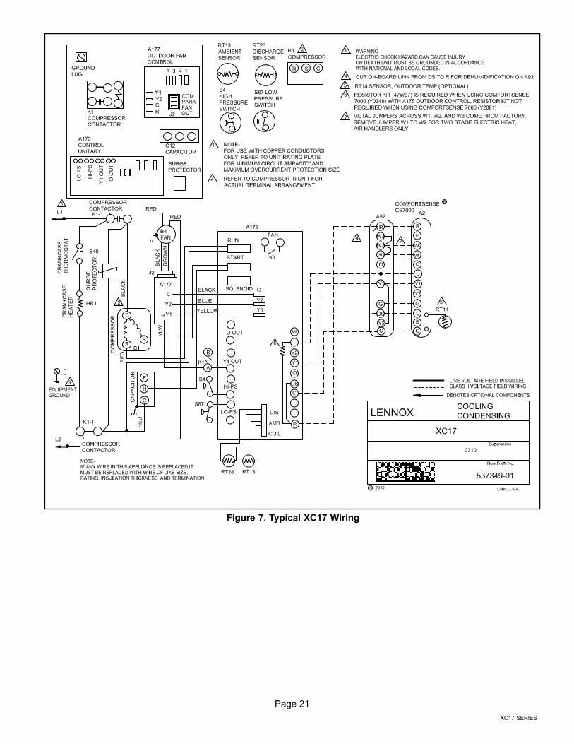
Figure 7. Typical XC17 Wiring

Page 22
506510−01
Main Control Jumpers and Terminals
MAIN CONTROL � AIR CONDITIONER � ONE STAGE
TABLE 3 PROVIDES ADDITIONAL INFORMATION CONCERNING JUMPERS, LOOP, AND CONNECTIONSFOR THE MAIN CONTROL.
DS13 and DS15
DS11 and DS14LED ALERT CODES
LED ALERT CODES
CUT FOR HUMIDITROL � ENHANCEDDEHUMIDIFICATION ACCESSORY (EDA)APPLICATIONS.
W1
E12
E16
E33
TEST PINS
Figure 8. Control Jumpers, Loop and Terminals

Page 23
XC17 SERIES
Table 3. Main Control Jumpers and Terminals
Board ID Label Description
E12 PSC Fan 240 VAC output connection for outdoor fan.
E16 PSC Fan 240 VAC input connection for outdoor fan.
E18
W 24VAC output for defrost auxiliary heat output.
L Thermostat service light connection.
Y2 24VAC thermostat input/output for second stage operation of the unit.
Y1 24VAC thermostat input for first stage operation of the unit.
O 24VAC thermostat input for reversing valve operation
DS Humiditrol Input
C 24VAC system common
R 24VAC system power input
E21 and E22 LO−PS S4 connection for low−pressure switch (2.4 milliamps @ 18VAC)
E31 and E32 Y1 OUT 24VAC common output, switched for enabling compressor contactor.
E24 and E25 HS−PS S87 connection for high−pressure switch.
E26 FAN 1First Stage and second stage basic and precision dehumidification ECM fan motor 24VDC out-put connection 1.
E27 FAN 2Second stage basic and precision dehumidification ECM fan motor 24VDC output connection2.
E28 FAN C ECM common connection for ECM fan.
E30
Six position square pin header E30 provides connections for the temperature sensors.
DIS (YELLOW)Pins 5 and 6
DIS 5 � Discharge line temperature sensor supply.
DIS 6 � Discharge line temperature sensor return.
Range is −35ºF to 310ºF. Sensor is clipped on a 1/2" copper tube.
AMB (BLACK)Pins 3 and 4
AMB 3 � Outdoor ambient temperature sensor supply.
AMB 4 � Outdoor ambient temperature return.
Range is −40ºF to +140ºF
COIL (BROWN)Pins 5 and 6
COIL 1 � Outdoor coil temperature sensor supply.
COIL 2 � Outdoor coil temperature sensor return
This model does not utilize a coil sensor. The cable harness assembly for the sensorsincorporates a built−in 10K resistor between pins 5 and 6.
E33 Field TestThis jumper allows service personnel to defeat the timed off control, and field programming ofunit capacity feature. Placing a jumper across both pins on E33 will terminate the anti−shortdelay. It will also clear lockout alarms
W1 Short DS To R Cut for Humiditrol � Enhanced Dehumidification Accessory (EDA) applications.
* Factory default setting

Page 24
506510−01
Field Control Wiring
Y1
O
R
W1
G
D
R
Y1
L
C
C
Air Handler ControlComfortSense� 7000 Thermostats
Catalog # Y0349 or Y2081One−StageAir Conditioner Control
B
Y2
Y2
W
O
DS
L
T
T
W2
H
W3
H
O
C
L
Y2
DS
DH
G
R
Y1
W2
W1
R connection required for outdoor unit with Control LSOM function. Resistor Kit (Cat# 47W97) is required when using the ComfortSense 7000 (Y0349) with Control LSOM feature. Resistor kit not required when using ComfortSense 7000 (Y2081).Air Handler Control comes from factory with metal jumpers across W1, W2 and W3. For one−stage electric heat, do not remove metal jumpers.
Outdoor sensor for outdoor temperature display (Optional).1
2
3
5
1
2
5
On−board link
Low voltage thermostat wiringFlat metal jumper
Air Handler Control comes from factory with metal jumpers across W1, W2 and W3. For two−stage electric heat, remove metal jumper between W1 to W2 and connect thermostat wire between Air Handler Control W2 to thermostat W2.
4
4
3
Cut for Humiditrol � Enhanced Dehumidification Accessory (EDA) applications.
Figure 9. ComfortSense® 7000 Series Thermostat � Air Hander/One−Stage Air Conditioner

Page 25
XC17 SERIES
Y1
O
R
W1
G
D
R
Y1
L
C
C
Furnace ControlComfortSense� 7000 Thermostats
Catalog # Y0349 or Y2081One−StageAir Conditioner Control
B
Y2
Y2
W
O
DS
L
T
T
W2
H
H
O
C
L
Y2
DS
DH
G
R
Y1
W2
W1
R connection required for outdoor unit with Control LSOM function. Resistor Kit (Cat# 47W97) is required when using the ComfortSense 7000 (Y0349) with Control LSOM feature. Resistor kit not required when usingComfortSense 7000 (Y2081).
Outdoor sensor for outdoor temperature display (Optional).
Cut on−board link (W914) (clippable wire) from DS to R for dehumidification (Optional).
1
2
3
1
2
3
On−board link
Low voltage thermostat wiring
Cut for Humiditrol � Enhanced Dehumidification Accessory (EDA) applications.
Figure 10. ComfortSense® 7000 Series Thermostat � Furnace/One−Stage Air Conditioner

Page 26
506510−01
Servicing Units Delivered Void of Charge
If the outdoor unit is void of refrigerant, clean the systemusing the procedure described below.
1. Leak check system using procedure outlined on Page16.
2. Evacuate the system using procedure outlined onPage 18.
3. Use nitrogen to break the vacuum and install a newfilter drier in the system.
4. Evacuate the system again using procedure outlinedon Page 18.
5. Weigh in refrigerant using procedure outlined in Figure14.
6. Monitor the system to determine the amount ofmoisture remaining in the oil. It may be necessary toreplace the filter drier several times to achieve therequired dryness level. If system dryness is notverified, the compressor will fail in the future.
Unit Start−Up
IMPORTANTIf unit is equipped with a crankcase heater, it should beenergized 24 hours before unit start−up to preventcompressor damage as a result of slugging.
1. Rotate fan to check for binding.
2. Inspect all factory− and field−installed wiring for looseconnections.
3. After evacuation is complete, open both the liquid andvapor line service valves to release the refrigerantcharge contained in outdoor unit into the system.
4. Replace the stem caps and tighten to the value listedin Table 1.
5. Check voltage supply at the disconnect switch. Thevoltage must be within the range listed on the unit’snameplate. If not, do not start the equipment until youhave consulted with the power company and thevoltage condition has been corrected.
6. Set the thermostat for a cooling demand. Turn onpower to the indoor indoor unit and close the outdoorunit disconnect switch to start the unit.
7. Recheck voltage while the unit is running. Power mustbe within range shown on the nameplate.
8. Check system for sufficient refrigerant by using theprocedures listed under System Charge.
System Refrigerant
This section outlines procedures for:
1. Connecting gauge set for testing and charging;
2. Checking and adjusting indoor airflow;
3. Adding or removing refrigerant.
TO LIQUIDLINE SERVICE
VALVE
TEMPERATURESENSOR
DIGITAL SCALE
REFRIGERANT TANK
TEMPERATURE SENSOR(LIQUID LINE)
MANIFOLD GAUGE SET
A Close manifold gauge set valves and connect the center hose to a cylinder of HFC−410A. Set for liquid phase charging.
B Connect the manifold gauge set’s low pressure side to the suction line service port.
C Connect the manifold gauge set’s high pressure side to the liquid line service port.
D Position temperature sensor on liquid line near liquid line service port.
OUTDOOR UNIT
CHARGE INLIQUID PHASE
CONNECTIONS FOR TESTING AND CHARGING
GAUGE SET
A
CD
LOW HIGH
B SUCTION LINESERVICE PORTCONNECTION
VAPOR LINESERVICE VALVE
LIQUID LINESERVICE VALVE
Figure 11. Gauge Set Setup and Connections
Page 27
XC17 SERIES
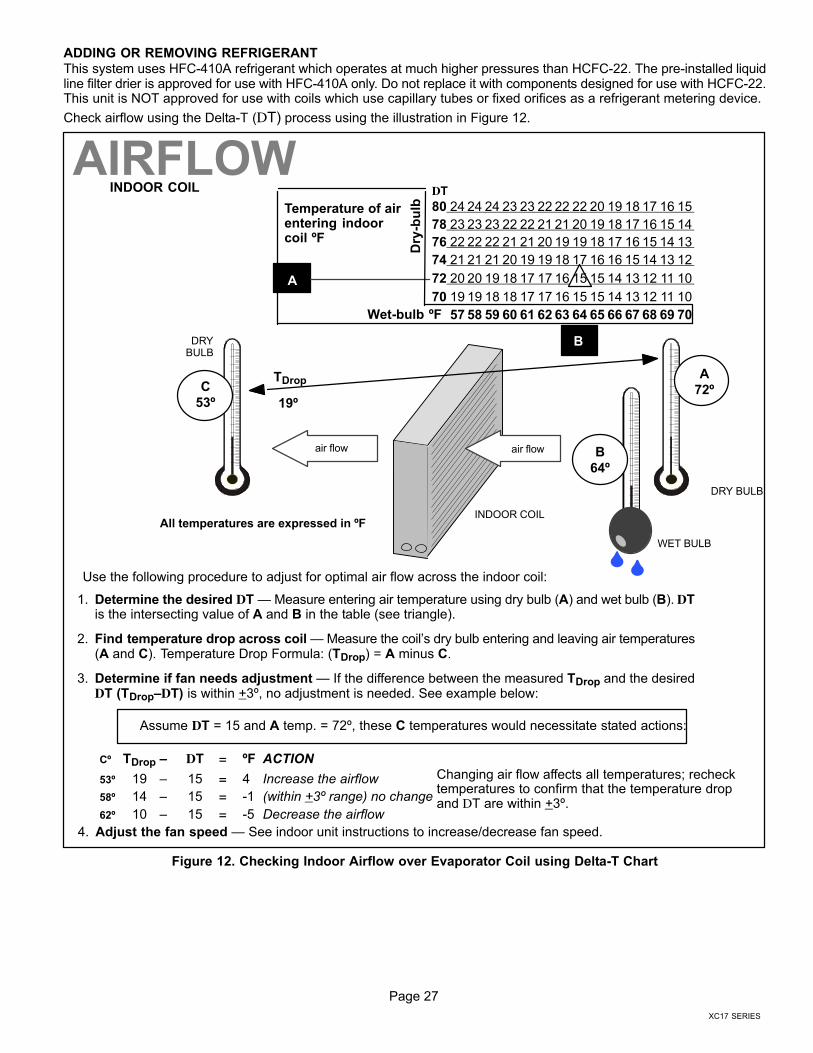
ADDING OR REMOVING REFRIGERANT
This system uses HFC−410A refrigerant which operates at much higher pressures than HCFC−22. The pre−installed liquidline filter drier is approved for use with HFC−410A only. Do not replace it with components designed for use with HCFC−22.This unit is NOT approved for use with coils which use capillary tubes or fixed orifices as a refrigerant metering device.
Check airflow using the Delta−T (DT) process using the illustration in Figure 12.
Cº TDrop – DT = ºF ACTION
53º 19 – 15 = 4 Increase the airflow
58º 14 – 15 = −1 (within +3º range) no change
62º 10 – 15 = −5 Decrease the airflow
DT
80 24 24 24 23 23 22 22 22 20 19 18 17 16 15
78 23 23 23 22 22 21 21 20 19 18 17 16 15 14
76 22 22 22 21 21 20 19 19 18 17 16 15 14 13
74 21 21 21 20 19 19 18 17 16 16 15 14 13 12
72 20 20 19 18 17 17 16 15 15 14 13 12 11 10
70 19 19 18 18 17 17 16 15 15 14 13 12 11 10
57 58 59 60 61 62 63 64 65 66 67 68 69 70
Temperature of airentering indoorcoil ºF
INDOOR COIL
DRY BULB
DRYBULB
WET BULB
B
TDrop
19º
A
Dry
−bu
lb
Wet−bulb ºF
A
72º
B
64º
C
53º
air flowair flow
All temperatures are expressed in ºF
1. Determine the desired DT � Measure entering air temperature using dry bulb (A) and wet bulb (B). DTis the intersecting value of A and B in the table (see triangle).
2. Find temperature drop across coil � Measure the coil’s dry bulb entering and leaving air temperatures(A and C). Temperature Drop Formula: (TDrop) = A minus C.
3. Determine if fan needs adjustment � If the difference between the measured TDrop and the desiredDT (TDrop–DT) is within +3º, no adjustment is needed. See example below:
4. Adjust the fan speed � See indoor unit instructions to increase/decrease fan speed.
Assume DT = 15 and A temp. = 72º, these C temperatures would necessitate stated actions:
AIRFLOW
Use the following procedure to adjust for optimal air flow across the indoor coil:
INDOOR COIL
Changing air flow affects all temperatures; rechecktemperatures to confirm that the temperature dropand DT are within +3º.
Figure 12. Checking Indoor Airflow over Evaporator Coil using Delta−T Chart

Page 28
506510−01
Use WEIGH IN to initially charge a system when the outdoor unit is void of charge. To verify charge and add or
remove refrigerant use either APPROACH or SUBCOOLING methods.
WHEN TO CHARGE?
� Warm weather best
� Can charge in colder weather
CHARGE METHOD? Determine by:
� Outdoor ambient temperature
REQUIREMENTS:
� Sufficient heat load in structure
� Indoor temperature between 70-80ºF (21−26ºC)
� Manifold gauge set connected to unit
� Thermometers:
− to measure outdoor ambient temperature
− to measure liquid line temperature
− to measure suction line temperature
TXV
APPROACH ORSUBCOOLING
65ºF
(18.3ºC) and
Above
START: Determine the correct charge method:
WEIGH-IN
64ºF
(17.7ºC) and
Below
Figure 13. Determining Charge Method
WEIGH IN
Liquid Line
Set Diameter
Ounces per 5 feet (g per 1.5 m)adjust from 15 feet (4.6 m) line set*
3/8" (9.5 mm) 3 ounce per 5’ (85 g per 1.5 m)
*If line length is greater than 15 ft. (4.6 m), add this amount. Ifline length is less than 15 ft. (4.6 m), subtract this amount.
Refrigerant Charge per Line Set Length
NOTE � The above nameplate is for illustration purposes only. Go to actual nameplate on outdoor unit forcharge information.
CHARGING METHOD
NOTE � Insulate liquid line when it is routed through areas where the surrounding ambient temperaturecould become higher than the temperature of the liquid line or when pressure drop is equal to or greaterthan 20 psig.
CALCULATING SYSTEM CHARGE FOR OUTDOOR UNIT VOID OF CHARGE
If the system is void of refrigerant, first, locate and repair any leaks and then weigh in the refrigerant charge into theunit. To calculate the total refrigerant charge:
Amount specified onnameplate
Adjust amount. for variationin line set length listed online set length table below.
Total charge
+ =
64ºF (17.7ºC) and Below
Figure 14. Using HFC−410A Weigh In Method
Page 29
XC17 SERIES
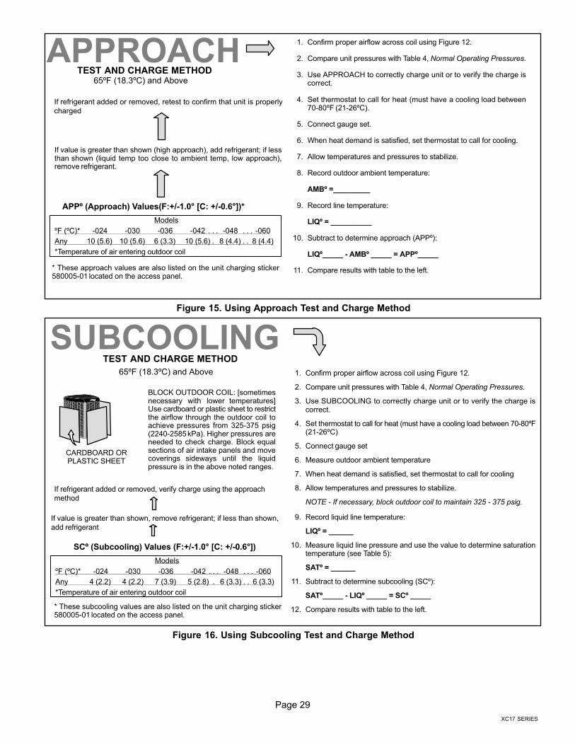
APPº (Approach) Values(F:+/−1.0° [C: +/−0.6°])*
If refrigerant added or removed, retest to confirm that unit is properly
charged
If value is greater than shown (high approach), add refrigerant; if lessthan shown (liquid temp too close to ambient temp, low approach),remove refrigerant.
1. Confirm proper airflow across coil using Figure 12.
2. Compare unit pressures with Table 4, Normal Operating Pressures.
3. Use APPROACH to correctly charge unit or to verify the charge iscorrect.
4. Set thermostat to call for heat (must have a cooling load between70-80ºF (21−26ºC).
5. Connect gauge set.
6. When heat demand is satisfied, set thermostat to call for cooling.
7. Allow temperatures and pressures to stabilize.
8. Record outdoor ambient temperature:
AMBº =_________
9. Record line temperature:
LIQº = __________
10. Subtract to determine approach (APPº):
LIQº_____ − AMBº _____ = APPº_____
11. Compare results with table to the left.
Models
ºF (ºC)* −024 −030 −036 −042 −048 −060. . . . . .
Any 10 (5.6) 10 (5.6) 6 (3.3) 10 (5.6) 8 (4.4) 8 (4.4). . .
*Temperature of air entering outdoor coil
65ºF (18.3ºC) and AboveTEST AND CHARGE METHOD
APPROACH
* These approach values are also listed on the unit charging sticker580005−01 located on the access panel.
Figure 15. Using Approach Test and Charge Method
SCº (Subcooling) Values (F:+/−1.0° [C: +/−0.6°])
If refrigerant added or removed, verify charge using the approach
method
If value is greater than shown, remove refrigerant; if less than shown,
add refrigerant
1. Confirm proper airflow across coil using Figure 12.
2. Compare unit pressures with Table 4, Normal Operating Pressures.
3. Use SUBCOOLING to correctly charge unit or to verify the charge iscorrect.
4. Set thermostat to call for heat (must have a cooling load between 70-80ºF(21−26ºC)
5. Connect gauge set
6. Measure outdoor ambient temperature
7. When heat demand is satisfied, set thermostat to call for cooling
8. Allow temperatures and pressures to stabilize.
NOTE − If necessary, block outdoor coil to maintain 325 − 375 psig.
9. Record liquid line temperature:
LIQº = ______
10. Measure liquid line pressure and use the value to determine saturationtemperature (see Table 5):
SATº = ______
11. Subtract to determine subcooling (SCº):
SATº_____ − LIQº _____ = SCº _____
12. Compare results with table to the left.
Models
ºF (ºC)* −024 −030 −036 −042 −048 −060. . . . . .
Any 4 (2.2) 4 (2.2) 7 (3.9) 5 (2.8) 6 (3.3) 6 (3.3). . .
*Temperature of air entering outdoor coil
SUBCOOLINGTEST AND CHARGE METHOD
65ºF (18.3ºC) and Above
* These subcooling values are also listed on the unit charging sticker580005−01 located on the access panel.
CARDBOARD ORPLASTIC SHEET
BLOCK OUTDOOR COIL: [sometimesnecessary with lower temperatures]Use cardboard or plastic sheet to restrictthe airflow through the outdoor coil toachieve pressures from 325−375 psig(2240−2585 kPa). Higher pressures areneeded to check charge. Block equalsections of air intake panels and movecoverings sideways until the liquidpressure is in the above noted ranges.
Figure 16. Using Subcooling Test and Charge Method

Page 30
506510−01
Operating and Temperature Pressures
Minor variations in these pressures may be expected due to differences in installations. Significant differences could meanthat the system is not properly charged or that a problem exists with some component in the system.
Table 4. Normal Operating Pressures (Liquid +10 and Suction +5 psig)*
IMPORTANTUse this table to perform maintenance checks; it is not a procedure for charging thesystem. Minor variations in these pressures may be due to differences in installations.Significant deviations could mean that the system is not properly charged or that aproblem exists with some component in the system.
Model −024 −030 −036 −042 −048 −060
°F (°C)** Liquid Suction Liquid Suction Liquid Suction Liquid Suction Liquid Suction Liquid Suction
65 (18.3) 234 139 236 134 226 134 232 137 232 132 236 131
70 (21.1) 249 140 251 135 245 135 249 139 249 133 254 132
75 (23.9) 268 141 271 138 266 137 270 140 268 134 273 133
80 (26.7) 289 142 291 139 287 138 291 141 288 135 294 135
85 (29.4) 310 142 312 140 310 139 314 142 311 136 317 136
90 (32.2) 334 144 335 142 333 140 338 143 333 137 340 137
95 (35.0) 358 145 358 142 358 141 363 144 357 138 364 139
100 (37.8) 383 146 383 143 383 143 389 145 380 139 389 140
105 (40.6) 408 147 409 144 410 144 419 147 406 140 416 142
110 (43.3) 436 148 436 145 437 145 447 148 433 142 444 143
115 (46.1) 465 150 467 147 464 146 480 149 462 143 475 145
* Typical pressures only, expressed in psig (liquid +/− 10 and vapor+/− 5 psig); indoor match up, indoor air quality, and indoor load will cause the pressures
to vary. These operating pressures are also listed on the unit charging sticker (580005−01) located on the access panel.
** Temperature of air entering outdoor coil.
Table 5. HFC−410A Temperature (° Fahrenheit) � Pressure (Psig)
°F Psig °F Psig °F Psig °F Psig °F Psig °F Psig °F Psig °F Psig
32 100.8 48 137.1 63 178.5 79 231.6 94 290.8 110 365.0 125 445.9 141 545.6
33 102.9 49 139.6 64 181.6 80 235.3 95 295.1 111 370.0 126 451.8 142 552.3
34 105.0 50 142.2 65 184.3 81 239.0 96 299.4 112 375.1 127 457.6 143 559.1
35 107.1 51 144.8 66 187.7 82 242.7 97 303.8 113 380.2 128 463.5 144 565.9
36 109.2 52 147.4 67 190.9 83 246.5 98 308.2 114 385.4 129 469.5 145 572.8
37 111.4 53 150.1 68 194.1 84 250.3 99 312.7 115 390.7 130 475.6 146 579.8
38 113.6 54 152.8 69 197.3 85 254.1 100 317.2 116 396.0 131 481.6 147 586.8
39 115.8 55 155.5 70 200.6 86 258.0 101 321.8 117 401.3 132 487.8 148 593.8
40 118.0 56 158.2 71 203.9 87 262.0 102 326.4 118 406.7 133 494.0 149 601.0
41 120.3 57 161.0 72 207.2 88 266.0 103 331.0 119 412.2 134 500.2 150 608.1
42 122.6 58 163.9 73 210.6 89 270.0 104 335.7 120 417.7 135 506.5 151 615.4
43 125.0 59 166.7 74 214.0 90 274.1 105 340.5 121 423.2 136 512.9 152 622.7
44 127.3 60 169.6 75 217.4 91 278.2 106 345.3 122 428.8 137 519.3 153 630.1
45 129.7 61 172.6 76 220.9 92 282.3 107 350.1 123 434.5 138 525.8 154 637.5
46 132.2 62 175.4 77 224.4 93 286.5 108 355.0 124 440.2 139 532.4 155 645.0
47 134.6 78 228.0 109 360.0 140 539.0

Page 31
XC17 SERIES
System Operation
IMPORTANTSome scroll compressor have internal vacuum protectorthat will unload scrolls when suction pressure goesbelow 20 psig. A hissing sound will be heard when thecompressor is running unloaded. Protector will resetwhen low pressure in system is raised above 40 psig. DONOT REPLACE COMPRESSOR.
The Main Control provides the following system functions:
� Compressor anti−short−cycle delay.
� High and low pressure switches
� Ambient and Discharge Line Temperatures Monitoring
and Protection.
� Five strikes lockout safety feature for High/Low
Pressure Switches and High Discharge LineTemperature. See Figures 19, 20 and 21 feature
function.
COMPRESSOR ANTI−SHORT CYCLE DELAY
The Main Control protects the compressor from:
� Short cycling (five minutes) when there is initial power
up
� Interruption in power to the unit
� High or low pressure switch or discharge line sensor
trips
� Delay after Y1 demand is removed.
The anti−short timer in the outdoor control is 5 minutes. Tooverride timer when active or inactive − place jumper on thefield test pins between 1 and 2 seconds.
Resetting Anti−Short Cycle Delay
The FIELD TEST pins (E33) on the Main Control can bejumpered between 1 to 2 seconds to bypass delay.
HIGH AND LOW PRESSURE SWITCHES
The unit’s reset pressure switches LO PS (S4) and HI PS(S87) are factory−wired into the Main Control on the LO−PSand HI−PS terminals, there locations are illustrated onPage 3. Sequence of operations for both pressureswitches are provided in Figures 19 and 20.
HIGH DISCHARGE LINE TEMPERATURE SENSOR(RT28)The high discharge line temperature sensor location isillustrated on Page 3. This sensor’s sequence ofoperations is provided in Figure 21.
High Discharge Line Sensor Open/Shorted EventCondition
Discharge sensor open / short fault is ignored during initial90−seconds of compressor run time. After that, if dischargetemperature sensor is detected open or short, the controlwill de−energize all the outputs and anti−short cycle timer isstarted. Discharge sensor faulty alert LED code will bedisplayed.
OUTDOOR AMBIENT TEMPERATURE (RT13)
If the outdoor ambient temperature sensor detected aopen, or out of range −40ºF to +140ºF (−40ºC to 60ºC) thenLED alert codes are displayed, however cooling operationwill continue. See Table 9 for LED alert codes for theambient sensor. Location of outdoor ambient temperaturesensor is illustrated on Page 3.
COIL TEMPERATURE SENSOR
This model does not use a coil temperature sensor. Thecable assembly attached to the Main Control’s E30connection has a 10K resister installed between pins 5 and6 as illustrated in Figure 17. No alerts or alarms would begenerated if resistor is damage.
10K resistor
High Discharge LineTemperature Sensor
Ambient AirTemperature Sensor
Figure 17. 10k Resistor Location
TESTING AMBIENT AND HIGH DISCHARGE LINETEMPERATURE SENSORS
Sensors connect through a field-replaceable harnessassembly that plugs directly into the Main Control.Through these sensors, the Main Control can monitoroutdoor ambient and discharge line temperature faultconditions. As the detected temperature changes, theresistance across the sensor changes. Figures 6 and 7lists how the resistance varies as the temperature changesfor both type of sensors. Sensor resistance values can bechecked by ohming across pins shown in Table 8.
When a sensor indicates a resistance value that is notwithin the range as listed in Table 8, then the followingcondition may be present:
� Sensor detects an out−of−range outdoor ambient air
temperature condition and will display LED alert codeon the Main Control.
� The sensor is operating normally when the ambient air
temperature at the sensor is below or above the Main
Control’s expected ohm values. The Main Control willindicate the sensor as faulty, however under this
scenario, the sensor is not actually faulty.
� Once the outdoor ambient air temperature has
returned to within the sensor’s normal operatingrange, the LED alert code will automatically stop.

Page 32
506510−01
TEST PINS FUNCTIONPlacing the JUMPER ON the field test pins (E33) (see Page 22 for location of TEST pins) allows the technician to
� Clear compressor anti−short cycle delay.
� Clear five−strike fault lockouts � High / Low pressure switches and High Discharge Temperature Sensor.
NOTES:
1 � Placing a JUMPER ON the TEST pins will not bring the unit out of inactive mode. The only way manuallyactivate the outdoor unit from an inactive mode is to cycle the 24VAC power to the outdoor unit’s Main Control.
2 � If the jumper remains on the TEST pins for longer than five seconds, the Main Control will ignore theJUMPER ON TEST pins and revert to normal operation.
Y1 Active
Place a JUMPER ON1 the TEST pins for longer than onesecond2. Then remove jumper and place in JUMPEROFF position.
Clears any short cycle lockout and five strike fault lockoutfunction, if applicable. No other functions will be executedand unit will continue in the mode it was operating.
JUMPEROFF
JUMPERON
FACTORY DEFAULTJUMPER SETTING
Figure 18. Clearing Anti−Short Cycle Delay and Five−Strike Fault Lockouts

Page 33
XC17 SERIES
Table 6. Ambient Sensor Temperature / Resistance RangeDegrees
FahrenheitResistance
DegreesFahrenheit
ResistanceDegrees
FahrenheitResistance
DegreesFahrenheit
Resistance
136.3 2680 56.8 16657 21.6 44154 −11.3 123152
133.1 2859 56.0 16973 21.0 44851 −11.9 125787
130.1 3040 55.3 17293 20.5 45560 −12.6 128508
127.3 3223 54.6 17616 20.0 46281 −13.2 131320
124.7 3407 53.9 17942 19.4 47014 −13.9 134227
122.1 3592 53.2 18273 18.9 47759 −14.5 137234
119.7 3779 52.5 18607 18.4 48517 −15.2 140347
117.5 3968 51.9 18945 17.8 49289 −15.9 143571
115.3 4159 51.2 19287 17.3 50074 −16.5 146913
113.2 4351 50.5 19633 16.8 50873 −17.2 150378
111.2 4544 49.9 19982 16.3 51686 −17.9 153974
109.3 4740 49.2 20336 15.7 52514 −18.6 157708
107.4 4937 48.5 20695 15.2 53356 −19.3 161588
105.6 5136 47.9 21057 14.7 54215 −20.1 165624
103.9 5336 47.3 21424 14.1 55089 −20.8 169824
102.3 5539 46.6 21795 13.6 55979 −21.5 174200
100.6 5743 46.0 22171 13.1 56887 −22.3 178762
99.1 5949 45.4 22551 12.5 57811 −23.0 183522
97.6 6157 44.7 22936 12.0 58754 −23.8 188493
96.1 6367 44.1 23326 11.5 59715 −24.6 193691
94.7 6578 43.5 23720 11.0 60694 −25.4 199130
93.3 6792 42.9 24120 10.4 61693 −26.2 204829
92.0 7007 42.3 24525 9.9 62712 −27.0 210805
90.6 7225 41.7 24934 9.3 63752 −27.8 217080
89.4 7444 41.1 25349 8.8 64812 −28.7 223677
88.1 7666 40.5 25769 8.3 65895 −29.5 230621
86.9 7890 39.9 26195 7.7 67000 −30.4 237941
85.7 8115 39.3 26626 7.2 68128 −31.3 245667
84.5 8343 38.7 27063 6.7 69281 −32.2 253834
83.4 8573 38.1 27505 6.1 70458 −33.2 262482
82.3 8806 37.5 27954 5.6 71661 −34.1 271655
81.2 9040 37.0 28408 5.0 72890 −35.1 281400
80.1 9277 36.4 28868 4.5 74147 −36.1 291774
79.0 9516 35.8 29335 3.9 75431 −37.1 302840
78.0 9757 35.2 29808 3.4 76745 −38.2 314669
77.0 10001 34.7 30288 2.8 78090 −39.2 327343
76.0 10247 34.1 30774 2.3 79465
75.0 10496 33.5 31267 1.7 80873
74.1 10747 33.0 31766 1.2 82314
73.1 11000 32.4 32273 0.6 83790
72.2 11256 31.9 32787 0.0 85302
71.3 11515 31.3 33309 −0.5 86852
70.4 11776 30.7 33837 −1.1 88440
69.5 12040 30.2 34374 −1.7 90068
68.6 12306 29.6 34918 −2.2 91738
67.7 12575 29.1 35471 −2.8 93452
66.9 12847 28.6 36031 −3.4 95211
66.0 13122 28.0 36600 −4.0 97016
65.2 13400 27.5 37177 −4.6 98870
64.4 13681 26.9 37764 −5.2 100775
63.6 13964 26.4 38359 −5.7 102733
62.8 14251 25.8 38963 −6.3 104746
62.0 14540 25.3 39577 −6.9 106817
61.2 14833 24.8 40200 −7.5 108948
60.5 15129 24.2 40833 −8.2 111141
59.7 15428 23.7 41476 −8.8 113400
59.0 15730 23.2 42130 −9.4 115727
58.2 16036 22.6 42794 −10.0 118126
57.5 16345 22.1 43468 −10.6 120600

Page 34
506510−01
Table 7. High Discharge Sensor Temperature / Resistance RangeDegrees
FahrenheitResistance
DegreesFahrenheit
ResistanceDegrees
FahrenheitResistance
DegreesFahrenheit
Resistance
303.1 183 186.1 1052 136.8 2656 94.5 6613
298.1 195 185.0 1072 136.0 2698 93.6 6739
293.4 207 183.9 1093 135.2 2740 92.8 6869
289.0 220 182.8 1114 134.5 2783 92.0 7002
284.8 232 181.8 1135 133.7 2827 91.2 7139
280.9 245 180.7 1157 132.9 2872 90.3 7281
277.1 258 179.6 1179 132.2 2917 89.5 7426
273.6 270 178.6 1201 131.4 2963 88.6 7575
270.2 283 177.6 1223 130.6 3010 87.8 7729
267.0 297 176.6 1245 129.9 3057 86.9 7888
263.9 310 175.5 1268 129.1 3105 86.0 8051
260.9 323 174.6 1291 128.4 3154 85.2 8220
258.1 336 173.6 1315 127.6 3204 84.3 8394
255.3 350 172.6 1338 126.8 3255 83.4 8574
252.7 364 171.6 1362 126.1 3307 82.5 8759
250.1 378 170.6 1386 125.3 3359 81.6 8951
247.7 391 169.7 1411 124.6 3413 80.7 9149
245.3 405 168.7 1435 123.8 3467 79.8 9354
243.0 420 167.8 1460 123.1 3523 78.8 9566
240.8 434 166.9 1486 122.3 3579 77.9 9786
238.6 448 165.9 1511 121.6 3637 76.9 10013
236.5 463 165.0 1537 120.8 3695 76.0 10250
234.4 478 164.1 1563 120.1 3755 75.0 10495
232.4 492 163.2 1590 119.3 3816 74.1 10749
230.5 507 162.3 1617 118.5 3877 73.1 11014
228.6 523 161.4 1644 117.8 3940 72.1 11289
226.7 538 160.5 1672 117.0 4005 71.1 11575
224.9 553 159.7 1699 116.3 4070 70.0 11873
223.2 569 158.8 1728 115.5 4137 69.0 12184
221.5 584 157.9 1756 114.8 4205 68.0 12509
219.8 600 157.1 1785 114.0 4274 66.9 12848
218.1 616 156.2 1815 113.2 4345 65.8 13202
216.5 632 155.3 1845 112.5 4418 64.7 13573
214.9 649 154.5 1875 111.7 4491 63.6 13961
213.4 665 153.6 1905 111.0 4567 62.5 14368
211.9 682 152.8 1936 110.2 4644 61.3 14796
210.4 698 152.0 1968 109.4 4722 60.2 15246
208.9 715 151.1 1999 108.7 4802 59.0 15719
207.5 732 150.3 2032 107.9 4884 57.8 16218
206.0 750 149.5 2064 107.1 4968 56.6 16744
204.6 767 148.7 2098 106.4 5054 55.3 17301
203.3 785 147.9 2131 105.6 5141 54.0 17891
201.9 803 147.1 2165 104.8 5231 52.7 18516
200.6 821 146.2 2200 104.0 5323 51.4 19180
199.3 839 145.4 2235 103.3 5416 50.0 19887
198.0 857 144.6 2270 102.5 5512 48.6 20641
196.8 876 143.8 2306 101.7 5610 47.2 21448
195.5 894 143.0 2343 100.9 5711 45.7 22311
194.3 913 142.3 2380 100.1 5814
193.1 932 141.5 2418 99.3 5920
191.9 952 140.7 2456 98.5 6028
190.7 971 139.9 2495 97.7 6139
189.5 991 139.1 2534 96.9 6253
188.4 1011 138.3 2574 96.1 6370
187.2 1031 137.6 2615 95.3 6489

Page 35
XC17 SERIES
Table 8. Sensor Temperature / Resistance Range
Sensor
TemperatureRange °F (°C)
Resistance valuesrange (ohms)
Pins/WireColor
Outdoor(Ambient)
−40ºF to 140ºF(−40ºC to 60ºC)
280,000 to 3750 3 and 4(Black)
Discharge −35ºF to 310ºF
(−37ºC to 154ºC)
41,000 to 103 1 and 2(Yellow)
Note: Sensor resistance decreases as sensed temperature increases(see Figures 6 and 7).
Main Control LED Alert Codes
Main Control LED alert codes (simply referred to as LEDalert codes) are located on the Main Control and markedwith the following identification.
DS11 AND DS14 LED SYSTEM AND ALERT CODES
DS11 (Green) and DS14 (Red) LEDs indicate diagnosticsconditions that are listed in Table 9.
These LEDs display fault conditions in system coolingcapacity, dehumidification mode, anti−short cycle lockout,high and low pressures, discharge line temperature,outdoor temperature, and discharge sensor failures.
DS15 AND DS13 LED COMPRESSOR ALERT CODES
DS15 (Yellow) and DS13 (Red) LEDs indicate diagnosticsconditions that are listed in Table 9.
These LEDs display the most common fault conditions inthe system. When an abnormal condition is detected, thisfunction communicates the specific condition throughLEDs. The diagnostic function is capable of detecting bothmechanical and electrical system abnormal conditions.
RESETTING LED ALERT CODES
LED alert codes can be reset either manually orautomatically:
1. Manual Reset
Manual reset can be achieve by one of the following
methods:
� Disconnect R wire from the Main Control’s R
terminal.
� Turning main power OFF and then ON at the unit’s
disconnect switch.
After power up, existing code will display for 60
seconds and then clear.
2. Automatic Reset
After an alert is detected, the Main Control continuesto monitor the unit’s system and compressoroperations. When/if conditions return to normal, thealert code is turned off automatically.
IMPORTANTLED alert codes do not provide safety protection. The is a monitoring function only and cannot control or shut down otherdevices.
Table 9. System LED Alert Codes
Outdoor Main ControlLEDs
Condition Possible Cause(s) SolutionDS11Green
DS14 Red
SYSTEM STATUS
OFF OFF Power problemNo power (24V) to controlterminals R and C orcontrol failure.
1 Check control transformer power (24V).2 If power is available to control and LED(s) do not light, replace control.
Simultaneous SLOWFlash
Normal operationUnit operating normally orin standby mode.
Indicates that control has internal component failure. Cycle 24 volt pow-er to control. If code does not clear, replace control.
Alternating SLOWFlash
5−minuteanti−short cycle
delay
Initial power up, safety trip,end of room thermostatdemand.
None required (Jumper FIELD TEST pins to override)
Simultaneous FASTFlash
Ambient SensorProblem
Sensor being detected open or shorted or out of temperature range. control will revert to time/temper-ature defrost operation. (System will still heat or cool).
Alternating FAST FlashCoil Sensor
Problem
This model does not utilize a coil sensor, however this alert indicates either an open or shorted circuit.See if 10K resistor is not damage or missing. Resistor is located in the sensor harness assembly,brown lead.
ON ONMain ControlBoard Failure
Indicates that control has internal component failure. Cycle 24 volt power to control. If code does notclear, replace control.

Page 36
506510−01
Outdoor Main ControlLEDs
SolutionPossible Cause(s)ConditionDS11Green
SolutionPossible Cause(s)Condition
DS14 RedDS11Green
SolutionPossible Cause(s)Condition
DS14 Red
OFF1 Fast
Flash thenPause
Heating LowCapacity
These are codes that show status of operation whether in low stage or high stage, heating or cooling,defrost or in the EDA mode.
OFF2 Fast
Flash thenPause
Heating HighCapacity
ON2 Fast
Flash thenPause
Defrost
1 FastFlash then
PauseOFF
Cooling LowCapacity
2 FastFlash then
PauseOFF
Cooling HighCapacity
2 FastFlash then
PauseON
DehumidificationMode
ALERT STATUS
OFFSLOWFlash
Low PressureFault
1 Restricted air flow overindoor or outdoor coil.
2 Improper refrigerantcharge in system.
3 Improper metering de-vice installed or incorrectoperation of metering de-vice.
4 Incorrect or impropersensor location or con-nection to system.
1 Remove any blockages or restrictions from coils and/or fans. Checkindoor and outdoor fan motor for proper current draws.
2 Check system charge using approach and subcooling temperatures.3 Check system operating pressures and compare to unit charging
charts.4 Make sure all pressure switches and sensors have secure connec-
tions to system to prevent refrigerant leaks or errors in pressure andtemperature measurements.
OFF ONLow Pressure
Switch Lockout
SLOWFlash
OFFHigh Pressure
Fault
ON OFFHigh Pressure
Discharge SensorLockout
SLOWFlash
ONDischarge Line
Temperature Fault This code detects high discharge temperatures. If the discharge line temperature exceeds a temperatureof 279ºF (137ºC) during compressor operation, the control will de−energize the compressor contactoroutput (and the defrost output if active). The compressor will remain off until the discharge temperaturehas dropped below 225ºF (107ºC). See Figure 21 for further details concerning lockouts and resetprocedures.
FASTFlash
ONDischarge LineTemperature
Lockout
OFF Fast FlashDischarge Sensor
Fault
The control detects open or short sensor or out of temperature sensor range. This fault is detected byallowing the unit to run for 90 seconds before checking sensor resistance. If the sensor resistance isnot within range after 90 seconds, the control will raise the alarm.
Fast simultaneousflashing of DS11, DS13,
DS14 and DS15
OEM Mode Factory Test Mode.

Page 37
XC17 SERIES
Table 10. Compressor LED Alert Codes
Outdoor MainControl LEDs
ConditionPossibleCause(s)
Solution Clearing StatusDS15Yellow
DS13Red
OFF ONCompressor
InternalOverload Trip
Thermostatdemand signal Y1is present, butcompressor notrunning
1 Compressor protector is open.
� Check for high head pressure
� Check compressor supply voltage2 Outdoor unit power disconnect is open.3 Compressor circuit breaker or fuse(s) is open.4 Broken wire or connector is not making contact.5 Low or high pressure switch open if present in the
system.6 Compressor contactor has failed to close.
Clears the error after currentis sensed in the run andstart winding for twoseconds, service removedor power reset.
1 FlashesthenPause
OFF Long run time.Compressor isrunning extremelylong run cycles.
1 Low refrigerant charge.2 Evaporator blower is not running.
� Check blower relay coil and contacts
� Check blower motor capacitor
� Check blower motor for failure or blockage
� Check evaporator blower wiring and connectors
� Check indoor blower control
� Check thermostat wiring for open circuit3 Evaporator coil is frozen.
� Check for low suction pressure
� Check for excessively low thermostat setting
� Check evaporator airflow (coil blockages or returnair filter)
� Check ductwork or registers for blockage.4 Faulty metering device.
� Check TXV bulb installation (size, location andcontact)
� Check if TXV/fixed orifice is stuck closed or de-fective
5 Condenser coil is dirty.
6 Liquid line restriction (filter drier blocked if present).
7 Thermostat is malfunctioning.
� Check thermostat sub−base or wiring for short cir-cuit
� Check thermostat installation (location and level)
Clears the error after 30consecutive normal runcycles, or after power reset.
2 FlashesthenPause
OFFSystem
Pressure Trip
Indicates thecompressorprotector is openor missing supplypower to thecompressor.
1 High head pressure.
� Check high pressure switch if present in system
� Check if system is overcharged with refrigerant
� Check for non−condensable in system2 Condenser coil poor air circulation (dirty, blocked,
damaged).3 Condenser fan is not running.
� Check fan capacitor
� Check fan wiring and connectors
� Check fan motor for failure or blockage4 Return air duct has substantial leakage.
Clears after fourconsecutive normalcompressor run cycles, orafter power reset.
3 FlashesthenPause
OFF Short CyclingCompressor isrunning less thanthree minutes.
1 Thermostat demand signal is intermittent.2 Time delay relay or Main Control is defective.3 If high pressure switch is present, see Flash Code 2
information.
Clears after fourconsecutive normalcompressor run cycles, orafter power reset.
4 FlashesthenPause.
OFF Locked Rotor
Compressor hasa locked out dueto run capacitorshort, bearingsare seized, ex-cessive liquid re-frigerant.
1 Run capacitor has failed.2 Low line voltage (contact utility if voltage at disconnect
is low).
� Check wiring connections3 Excessive liquid refrigerant in the compressor.4 Compressor bearings are seized.
Clears after power reset orfour normal compressorcycles.

Page 38
506510−01
Outdoor MainControl LEDs
Clearing StatusSolutionPossibleCause(s)
ConditionDS15Yellow
Clearing StatusSolutionPossibleCause(s)
ConditionDS13Red
5 FlashesthenPause
OFF Open Circuit
Compressor hasan open circuitdue to power dis-connection, fuseis open or othersimilar conditions.
1 Outdoor unit power disconnect is open.2 Unit circuit breaker or fuse(s) is open.3 Unit contactor has failed to close.
� Check compressor contactor wiring and con-nectors
� Check for compressor contactor failure (burned,pitted or open)
� Check wiring and connectors between supply andcompressor
� Check for low pilot voltage at compressor con-tactor coil
4 High pressure switch is open and requires manualreset.
5 Open circuit in compressor supply wiring or con-nections.
6 Unusually long compressor protector reset time dueto extreme ambient temperature.
7 Compressor windings are damaged.
� Check compressor motor winding resistance
Clears after one normalcompressor run cycle orpower reset.
6 FlashesthenPause
OFFOpen Start
Circuit
Current notsensed by Starttransformer.
1 Run capacitor has failed.2 Open circuit in compressor start wiring or connec-
tions.
� Check wiring and connectors between supply andthe compressor S terminal
3 Compressor start winding is damaged.
� Check compressor motor winding resistance
Clears when amperage isdetected in RUN andSTART sensors, or afterpower reset.
7 FlashesthenPause
OFFOpen Run
Circuit
Current notsensed by runtransformer.
1 Open circuit in compressor start wiring or connections.
� Check wiring and connectors between supply andthe compressor R terminal
2 Compressor start winding is damaged.
� Check compressor motor winding resistance
Clears when amperage isdetected in RUN andSTART sensors, or afterpower reset.
8 FlashesthenPause
OFFWelded
ContactorCompressoralways runs
1 Compressor contactor failed to open.2 Thermostat demand signal not connected to module.
Clears after one normalcompressor run cycle orafter power reset.
9 FlashesthenPause
OFFSecondary
Low Voltage24VAC is below18VAC.
1 Control circuit transformer is overloaded.2 Low line voltage (contact utility if voltage at disconnect
is low).
� Check wiring connections
Clears after voltage is higherthan 20VAC for twoseconds, or after powerreset.
Fast simultaneousflashing of DS11,DS13, DS14 and
DS15
OEM Mode Factory Test Mode.

Page 39
XC17 SERIES
Figure 19. High Pressure Switch Operation

Page 40
506510−01
Figure 20. Low Pressure Switch Operation
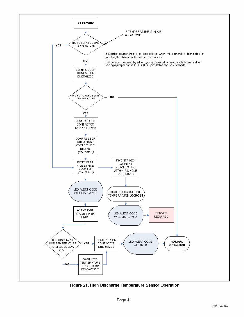
Page 41
XC17 SERIES
Figure 21. High Discharge Temperature Sensor Operation
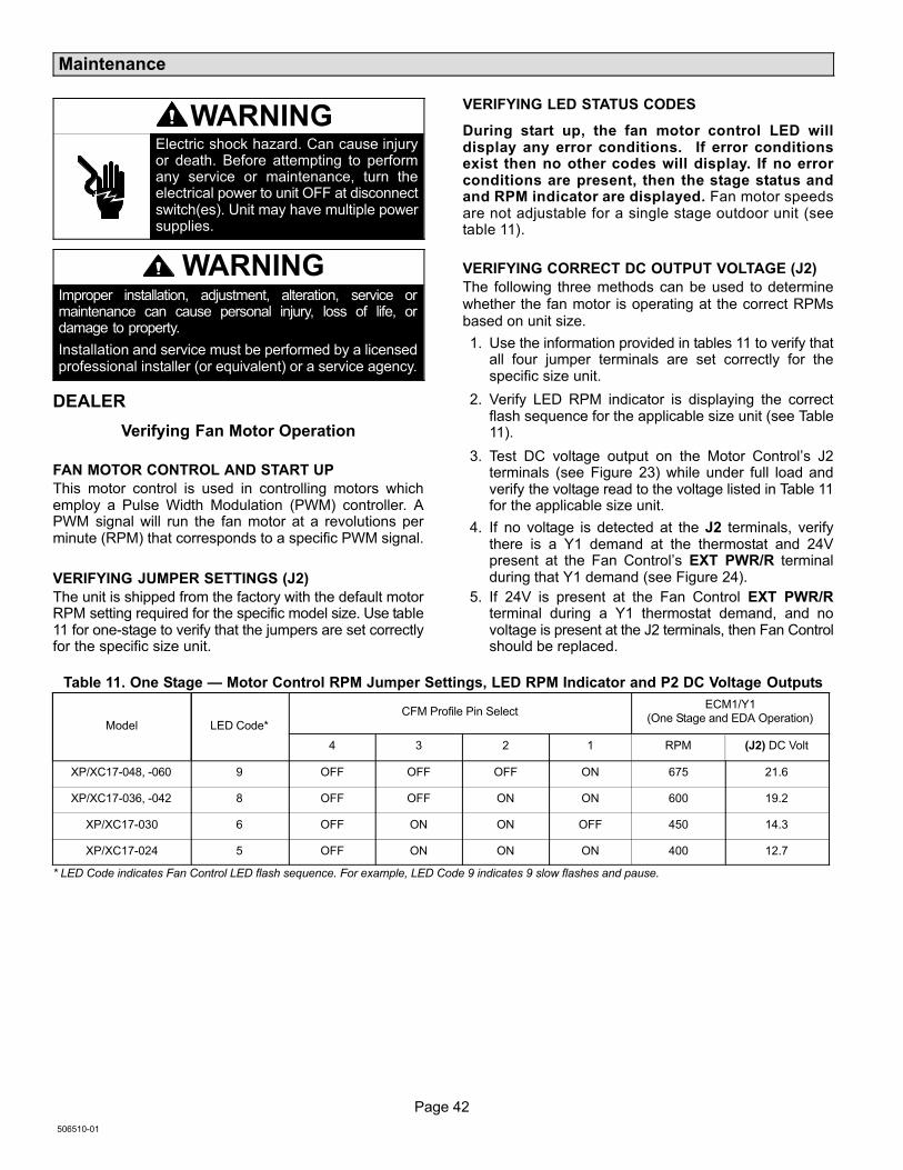
Page 42
506510−01
Maintenance
WARNINGElectric shock hazard. Can cause injuryor death. Before attempting to performany service or maintenance, turn theelectrical power to unit OFF at disconnectswitch(es). Unit may have multiple powersupplies.
WARNINGImproper installation, adjustment, alteration, service ormaintenance can cause personal injury, loss of life, ordamage to property.
Installation and service must be performed by a licensedprofessional installer (or equivalent) or a service agency.
DEALER
Verifying Fan Motor Operation
FAN MOTOR CONTROL AND START UP
This motor control is used in controlling motors whichemploy a Pulse Width Modulation (PWM) controller. APWM signal will run the fan motor at a revolutions perminute (RPM) that corresponds to a specific PWM signal.
VERIFYING JUMPER SETTINGS (J2)
The unit is shipped from the factory with the default motorRPM setting required for the specific model size. Use table11 for one−stage to verify that the jumpers are set correctlyfor the specific size unit.
VERIFYING LED STATUS CODES
During start up, the fan motor control LED willdisplay any error conditions. If error conditionsexist then no other codes will display. If no errorconditions are present, then the stage status andand RPM indicator are displayed. Fan motor speedsare not adjustable for a single stage outdoor unit (seetable 11).
VERIFYING CORRECT DC OUTPUT VOLTAGE (J2)
The following three methods can be used to determinewhether the fan motor is operating at the correct RPMsbased on unit size.
1. Use the information provided in tables 11 to verify thatall four jumper terminals are set correctly for thespecific size unit.
2. Verify LED RPM indicator is displaying the correctflash sequence for the applicable size unit (see Table11).
3. Test DC voltage output on the Motor Control’s J2terminals (see Figure 23) while under full load andverify the voltage read to the voltage listed in Table 11for the applicable size unit.
4. If no voltage is detected at the J2 terminals, verifythere is a Y1 demand at the thermostat and 24Vpresent at the Fan Control’s EXT PWR/R terminalduring that Y1 demand (see Figure 24).
5. If 24V is present at the Fan Control EXT PWR/Rterminal during a Y1 thermostat demand, and novoltage is present at the J2 terminals, then Fan Controlshould be replaced.
Table 11. One Stage � Motor Control RPM Jumper Settings, LED RPM Indicator and P2 DC Voltage Outputs
Model LED Code*
CFM Profile Pin SelectECM1/Y1
(One Stage and EDA Operation)
4 3 2 1 RPM (J2) DC Volt
XP/XC17−048, −060 9 OFF OFF OFF ON 675 21.6
XP/XC17−036, −042 8 OFF OFF ON ON 600 19.2
XP/XC17−030 6 OFF ON ON OFF 450 14.3
XP/XC17−024 5 OFF ON ON ON 400 12.7
* LED Code indicates Fan Control LED flash sequence. For example, LED Code 9 indicates 9 slow flashes and pause.

Page 43
XC17 SERIES
LED CODES AND SEQUENCE OF OPERATIONS
During start up, the LED will first display any error conditions (see table 12) if present. If no errors are detected then the LEDcode indicating one or two stage operation will display then a long pause. The RPM indicator is displayed next. After the RPMindicator is displayed there is a short pause and the sequence repeats if a thermostat demand is still present. See Figure 22for LED sequence of operations. See table 13 for description of flash and pause durations.
Table 12. Error/Fault LED Codes
Unit Status Motor Control LED Possible Cause
Mismatched RPM Fast Flash with no pauseInternal feedback, PWM does not match tar-get.
CRC Failure Constant ON. Microcontroller CRC failure.
Table 13. Fan Motor Board Unit LED Codes
Unit Status Unit Status Motor Control LED
One Stage Operation Low Stage � ECM1/Y1 ONLY One slow flash, then short pause.
RPM Indicator
NOTE � There is a long pause between stage
operation and RPM indicator. See Tables 1 and 2
for LED RPM indicator.
RPM IndicatorAppropriate number of flashes (See Tables11 and 2).
Flash Flash = Three flashes per second.
Slow Flash = One flash per second.
Short Pause = Two seconds of OFF time.
Long Pause = Five seconds of OFF time.
DEMANDBEGINS
MISMATCHEDRPM
DEFAULT FANMOTOR SPEED
USED LED CONTINUOUS FASTFLASH
REPLACE FAN MOTORCONTROL BOARD
CRC FAILURE
DEFAULT FANMOTOR SPEED
USED
LED CONSTANT ON REPLACE FAN MOTORCONTROL BOARD
SINGLE STAGE
OR EDAOPERATION
FAN MOTOR PWM CONTROL (ONE STAGE ANDSINGLE FAN SPEED)
ECM1/Y1ONLY ORECM2/Y2
ONLY
STAGE LED INDICATOR: ONE SLOW FLASH AND ONESHORT PAUSE FOR SINGLE STAGE OR EDA OPERATION
LED RPM INDICATOR: EXAMPLE: (2−TONUNIT) – 5 SLOW FLASHES AND ONELONG PAUSEDEMAND
ENDED
NO
YESFAN MOTOR
RPM SET PERJUMPER
SETTINGS
Figure 22. Single Stage LED Sequence of Operation

Page 44
506510−01
MAIN CONTROLCONTROL PANEL
FAN MOTOR CONTROL �PULSE−WIDTH MODULATION (PWM)
JUMPEROFF
JUMPERON
J2
LED
CFM Profile Pin Select
VERIFY DC VOLTAGE OUTPUT USING FAN PWM OUT ANDCOM TERMINALS. SEE TABLE 11 FOR OPTIMAL DCVOLTAGE BASED ON CFM PROFILE USED.
COM
FAN PWM OUT
GREEN
RED
BROWN
RED
BLACK
YELLOWYELLOW
RED
RED
BLACK
GREEN
YELLOW BLACKPWM FANCONTROL
YELLOW
BLACK
YELLOW
BLUE
SEE TABLE 11 FOR CFM PROFILE SELECTION OPTIONS.
FA
N P
WM
OU
TP
AR
KC
OM
J2
Figure 23. Fan Control, Wiring, Jumper Settings, Testing and LED Location

Page 45
XC17 SERIES
MAIN CONTROLCONTROL PANEL
FAN MOTOR CONTROL �PULSE−WIDTH MODULATION (PWM)
COM
YELLOW WIRE
GREEN
RED
BROWN
RED
BLACK
YELLOWYELLOW
RED
RED
BLACK
GREEN
YELLOW BLACKPWM FANCONTROL
YELLOW
BLACK
YELLOW
BLUE
SEE TABLE 11 FOR CFM PROFILE SELECTION OPTIONS.
TO MAIN CONTROL
EXT PWR/R
BLACK WIRE
Figure 24. Testing for External Power to Fan Control
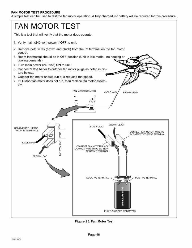
Page 46
506510−01
FAN MOTOR TEST PROCEDURE
A simple test can be used to test the fan motor operation. A fully charged 9V battery will be required for this procedure.
J2
FA
N P
WM
OU
TP
AR
KC
OM
BLACK LEAD
BROWN LEAD
BROWN LEADBLACK LEAD
REMOVE BOTH LEADSFROM J2 TERMINALS
CONNECT FAN MOTOR BLACKCOMMON WIRE TO 9V BATTERY
NEGATIVE TERMINAL
FAN MOTOR CONTROL BLACK LEAD BROWN LEAD
FAN MOTOR TEST
FULLY CHARGED 9V BATTERY
This is a test that will verify that the motor does operate.
J2
1. Verify main (240 volt) power if OFF to unit.
2. Remove both wires (brown and black) from the J2 terminal on the fan motorcontrol.
3. Room thermostat should be in OFF position (Unit in idle mode − no heating orcooling demands)
4. Turn main power (240 volt) ON to unit.
5. Connect 9 Volt batter to outdoor fan motor plugs as noted in pic-ture below..
6. Outdoor fan motor should run at a reduced fan speed.
7. If Outdoor fan motor does not run, then replace fan motor assem-bly.
NEGATIVE TERMINAL POSITIVE TERMINAL
CONNECT FAN MOTOR WIRE TO9V BATTERY POSITIVE TERMINAL
V
Figure 25. Fan Motor Test

Page 47
XC17 SERIES
FAN MOTOR SURGE PROTECTION
Surge Protector (Metal Oxide Varistor − MOV) − A partdesigned to protect electrical devices from voltage spikesthat are 3 to 4 times the normal circuit voltage (See Figure26 for illustration of component).
An MOV works as follows: It is essentially a batch ofmetallic−oxide grains separated by insulating layers.Repeated voltage surges break down the insulating layers,lowering the overall resistance and eventually causing thedevice to draw too much current and trip whateverover−current protection is inherent in the system)
MOV Check: They are supposed to be located beyond theline fuse (though possibly not always). In this case, wherethe line fuse blows or circuit breaker trips but there is novisible damage to the MOV(s), the simplest test may be tojust temporarily remove the MOV(s) and see if the problemgoes away.
See Figure 1 for location of the Surge Protections devicewhich is located in the unit control box area.
Figure 26. Fan Motor Surge Protection Device
Outdoor Unit
Maintenance and service must be performed by a qualifiedinstaller or service agency. At the beginning of eachcooling season, the system should be checked as follows:
1. Outdoor unit fan motor is pre−lubricated and sealed.No further lubrication is needed.
2. Visually inspect all connecting lines, joints and coils forevidence of oil leaks.
3. Check all wiring for loose connections.
4. Check for correct voltage at unit (unit operating).
5. Check amperage draw on outdoor fan motor.
Motor Nameplate:_________ Actual:__________.
6. Inspect drain holes in coil compartment base andclean if necessary.
NOTE - If insufficient cooling occurs, the unit should be
gauged and refrigerant charge should be checked.
Outdoor Coil
Clean and inspect outdoor coil (may be flushed with awater hose). Ensure power is off before cleaning.
NOTE � It may be necessary to flush the outdoor coil
more frequently if it is exposed to substances which are
corrosive or which block airflow across the coil (e.g., pet
urine, cottonwood seeds, fertilizers, fluids that may contain
high levels of corrosive chemicals such as salts)
Sea Coast � Moist air in ocean locations can carry salt,which is corrosive to most metal. Units that are locatednear the ocean require frequent inspections andmaintenance. These inspections will determine thenecessary need to wash the unit including the outdoor coil.Consult your installing contractor for properintervals/procedures for your geographic area or servicecontract.
Indoor Unit1. Clean or change filters.
2. Lennox blower motors are prelubricated andpermanently sealed. No more lubrication is needed.
3. Adjust blower speed for cooling. Measure the pressuredrop over the coil to determine the correct blower CFM.Refer to the unit information service manual for pressuredrop tables and procedure.
4. Belt Drive Blowers − Check belt for wear and propertension.
5. Check all wiring for loose connections.
6. Check for correct voltage at unit. (blower operating)
7. Check amperage draw on blower motor.
Motor Nameplate:_________ Actual:__________.
Indoor Coil1. Clean coil if necessary.
2. Check connecting lines, joints and coil for evidence ofoil leaks.
3. Check condensate line and clean if necessary.
HOMEOWNERCleaning of the outdoor unit’s coil should be performed bya trained service technician. Contact your dealer and setup a schedule (preferably twice a year, but at least once ayear) to inspect and service your outdoor unit. Thefollowing maintenance may be performed by thehomeowner.
CAUTIONPhysical contact with metal edges and corners whileapplying excessive force or rapid motion can result inpersonal injury. Be aware of, and use caution whenworking near these areas during installation or whileservicing this equipment.
IMPORTANTSprinklers and soaker hoses should not be installedwhere they could cause prolonged exposure to theoutdoor unit by treated water. Prolonged exposure of theunit to treated water (i.e., sprinkler systems, soakers,waste water, etc.) will corrode the surface of steel andaluminum parts and diminish performance and longevityof the unit.

Page 48
506510−01
Outdoor CoilThe outdoor unit must be properly maintained to ensure itsproper operation.
� Please contact your dealer to schedule proper
inspection and maintenance for your equipment.
� Make sure no obstructions restrict airflow to the
outdoor unit.
� Grass clippings, leaves, or shrubs crowding the unit
can cause the unit to work harder and use more
energy.
� Keep shrubbery trimmed away from the unit and
periodically check for debris which collects around theunit.
Routine Maintenance
In order to ensure peak performance, your system must beproperly maintained. Clogged filters and blocked airflowprevent your unit from operating at its most efficient level.
1. Air Filter � Ask your Lennox dealer to show youwhere your indoor unit’s filter is located. It will be eitherat the indoor unit (installed internal or external to thecabinet) or behind a return air grille in the wall orceiling. Check the filter monthly and clean or replaceit as needed.
2. Disposable Filter � Disposable filters should bereplaced with a filter of the same type and size.
NOTE � If you are unsure about the filter required for your
system, call your Lennox dealer for assistance.
3. Reusable Filter � Many indoor units are equippedwith reusable foam filters. Clean foam filters with amild soap and water solution; rinse thoroughly; allowfilter to dry completely before returning it to the unit orgrille.
NOTE � The filter and all access panels must be in place
any time the unit is in operation.
4. Electronic Air Cleaner � Some systems areequipped with an electronic air cleaner, designed toremove airborne particles from the air passing throughthe cleaner. If your system is so equipped, ask yourdealer for maintenance instructions.
5. Indoor Unit � The indoor unit’s evaporator coil isequipped with a drain pan to collect condensateformed as your system removes humidity from the
inside air. Have your dealer show you the location ofthe drain line and how to check for obstructions. (Thiswould also apply to an auxiliary drain, if installed.)
Thermostat OperationSee the ComfortSense® 7000 thermostat homeownermanual for instructions on how to operate your thermostat.
Preservice Check
If your system fails to operate, check the following beforecalling for service:
� Verify room thermostat settings are correct.
� Verify that all electrical disconnect switches are ON.
� Check for any blown fuses or tripped circuit breakers.
� Verify unit access panels are in place.
� Verify air filter is clean.
� If service is needed, locate and write down the unit
model number and have it handy before calling.
AccessoriesFor update−to−date information, see any of the followingpublications:
� Lennox XC17 Engineering Handbook
� Lennox Product Catalog
� Lennox Price Book
WARNINGThis product and/or the indoor unit it is matched with maycontain fiberglass wool.
Disturbing the insulation during installation,maintenance, or repair will expose you to fiberglass wooldust. Breathing this may cause lung cancer. (Fiberglasswool is known to the State of California to cause cancer.)
Fiberglass wool may also cause respiratory, skin, andeye irritation.
To reduce exposure to this substance or for furtherinformation, consult material safety data sheetsavailable from address shown below, or contact yoursupervisor.
Lennox Industries Inc.P.O. Box 799900Dallas, TX 75379−9900
XC17 Start−Up and Performance Checklist
Customer Address
Indoor Unit Model Serial
Outdoor Unit Model Serial
Notes:
START UP CHECKS
Refrigerant Type:
Rated Load Amps Actual Amps Rated Volts Actual Volts
Condenser Fan Full Load Amps Actual Amps:
COOLING MODE

Page 49
XC17 SERIES
XC17 Start−Up and Performance Checklist
Suction Pressure: Liquid Pressure:
Supply Air Temperature: Ambient Temperature: Return Air: Temperature:
System Refrigerant Charge (Refer to manufacturer’s information on unit or installation instructions for required subcooling and approachtemperatures.)
Subcooling: A � B = SUBCOOLING
Saturated Condensing Temperature (A)minus Liquid Line Temperature (B)
Approach: A � B = APPROACH
Liquid Line Temperature (A)minus Outdoor Air Temperature (B)
Indoor Coil Temperature Drop (18 to 22°F) A � B = COIL TEMP DROP
Return Air Temperature (A)minus Supply Air Temperature (B)