Embed Size (px)
Citation preview
Page 1506904−01
����������04/12
�������
�2012 Lennox Industries Inc.Dallas, Texas, USA
RETAIN THESE INSTRUCTIONSFOR FUTURE REFERENCE
SLO183UFV SERIES UNITS ARE NOT FORUSE IN ZONING APPLICATIONS!
WARNINGImproper installation, adjustment, alteration, ser-vice, or maintenance can cause injury or propertydamage. Refer to this manual. For assistance oradditional information, consult a licensed profes-sional installer, or equivalent, or service agency.
WARNINGDo not store or use gasoline or other flammable va-pors and liquids in the vicinity of this or any otherappliance.
CAUTIONWhen venting this appliance, keep vent terminalfree of snow, ice and debris.
CAUTIONAs with any mechanical equipment, personal injurycan result from contact with sharp sheet metaledges. Be careful when you handle this equipment.
INSTALLATIONINSTRUCTIONS
SLO183UFV Series Units
OIL UNITS
506904−01
04/2012
Table of Contents
General 1. . . . . . . . . . . . . . . . . . . . . . . . . . . . . . . . . . . . . . Shipping & Packing List 1. . . . . . . . . . . . . . . . . . . . . . . . SLO183UFV Unit Dimensions 2. . . . . . . . . . . . . . . . . . . SLO183UFV Unit Parts Arrangement 3. . . . . . . . . . . . SLO183UFV Oil Burner Parts Arrangement 3. . . . . . . . . Requirements 4. . . . . . . . . . . . . . . . . . . . . . . . . . . . . . . . . Combustion & Ventilation Air 5. . . . . . . . . . . . . . . . . . . . Locate & Level the Unit 6. . . . . . . . . . . . . . . . . . . . . . . . Adjustments 7. . . . . . . . . . . . . . . . . . . . . . . . . . . . . . . . . . Venting 7. . . . . . . . . . . . . . . . . . . . . . . . . . . . . . . . . . . . . . Flue Connections 9. . . . . . . . . . . . . . . . . . . . . . . . . . . . . . Supply & Return Air Plenums 10. . . . . . . . . . . . . . . . . . . Oil Supply Line Sizing 10. . . . . . . . . . . . . . . . . . . . . . . . . . Oil Supply Line & Filter Connections 11. . . . . . . . . . . . . Leak Check 12. . . . . . . . . . . . . . . . . . . . . . . . . . . . . . . . . . . Electrical 12. . . . . . . . . . . . . . . . . . . . . . . . . . . . . . . . . . . . . Blower Control 16. . . . . . . . . . . . . . . . . . . . . . . . . . . . . . . . Unit Start Up & Adjustments 19. . . . . . . . . . . . . . . . . . . . Service 20. . . . . . . . . . . . . . . . . . . . . . . . . . . . . . . . . . . . . . Burner Control 21. . . . . . . . . . . . . . . . . . . . . . . . . . . . . . . . Troubleshooting 22. . . . . . . . . . . . . . . . . . . . . . . . . . . . . . .
General
These instructions are intended as a general guide and donot supersede local codes in any way. Only licensed pro-
fessional technicians, or equivalent, can install and servicethe Dave Lennox Signature� Collection SLO183UFV oilfurnaces. In Canada, refer to CSA B139 for recommendedinstallation procedures. Consult authorities who have juris-diction before installation.
CAUTIONNever burn garbage or paper in the heating system.Never leave papers near or around the unit.
Shipping & Packing List
1 − Assembled oil furnace
1 − Barometric draft control
1 − Oil nozzle (used with SLO183UF86, −114 and −150
only)
Check the components for shipping damage. If you findany damage, immediately contact the last carrier.
Litho U.S.A.

Page 2
SLO183UFV Unit Dimensions − Inches (mm)
SUPPLY
AIR
OPENING FLUE
CONNECTION
(On Heat
Exchanger)
22
(559)14
(356)
2 (51)
1-1/2
(38)
23-1/2
(597)
54
(1372)
1-1/2 (38)
3/4 (19)
22
(559)1-1/4 (32)
TOP FLUE OUTLET
SIDE FLUE OUTLETCENTERING HOLE
(Field Fabricate Either Side)
ELECTRICAL INLET(Right Side Only)
OIL PIPING INLET(Left Side Only)
OPT. OUTDOOR COMBUSTIONAIR INLET CENTERING HOLE(Field Fabricate Right Side only)
RETURN AIR OPENING(Either Side)
3/4 (19)
AB
C
D
AIR FLOW
TOP VIEW
RETURN AIR SIDE VIEW
E
RETURN AIR FRONT VIEW
Figure 1
SLO183UFV Unit Dimensions − Inches (mm)
SLO183UFVModel
A B C D E
68/86V36101/114V42
19−1/2(495)
30−5/8(778)
18(457)
19−5/8(498)
16(406)
135/150V6022−1/2(572)
33−1/8(841)
21(533)
22−1/8(562)
18(457)

Page 3
SLO183UFV Unit Parts Arrangement
CLEAN−OUT PORT
CLEAN−OUT PORT
BECKETTAFG BURNER
VARIABLESPEED BLOWER
MOTOR
OBSERVATIONPORT
HEATEXCHANGERFLUE
COLLAR
LIMIT SWITCH
INDOOR BLOWER
CAPACITORBLOWER CONTROL
Figure 2
SLO183UFV AFG Burner Parts Arrangement
ESCUTCHEONPLATE
MAINHOUSING
HEATSHIELD
BURNER CONTROL(with Reset Button)
OIL DELAYVALVE
AIR TUBE WITHELECTRODE
ASSEMBLY ANDNOZZLE INSIDE
BLOWER WHEELWITH AIR GUIDE(Inside housing)
COPPER OILTUBE
BLOWERMOTOR
IGNITER
AIR BAND ANDAIR SHUTTER
FUEL PUMP
Figure 3
Page 4
Requirements
WARNINGThis product contains fiberglass wool.
Disturbing the insulation during installation, main-tenance, or repair will expose you to fiberglass wooldust. Breathing this may cause lung cancer. (Fiber-glass wool is known to the State of California tocause cancer.)
Fiberglass wool may also cause respiratory, skin,and eye irritation.
To reduce exposure to this substance or for furtherinformation, consult material safety data sheetsavailable from address shown below, or contactyour supervisor.
Lennox Industries Inc.P.O. Box 799900Dallas, TX 75379−9900
Installation of Lennox oil−fired furnaces must conform withthe National Fire Protection Association Standard for theInstallation of Oil Burning Equipment, NFPA No. 31, theNational Electrical Code, ANSI/NFPA No.70 (in theU.S.A.), CSA Standard CAN/CSA−B139 (in Canada),Installation Code for Oil Burning Equipment, the CanadianElectrical Code Part1, CSA 22.1 (Canada), the recom-mendations of the National Environmental Systems Con-tractors Association and any state or provincial laws or lo-cal ordinances. Authorities having jurisdiction should beconsulted before installation. Such applicable regulationsor requirements take precedence over general instructionsin this manual.
Chimneys and chimney connectors must be of the typeand construction outlined in section 160 of NFPA No. 31.
Air for combustion and ventilation must conform to stan-dards outlined in section 140 of NFPA No. 31 or, in Cana-da, CSA Standard B139. When installing SLO183UFVunits in confined spaces such as utility rooms, two com-bustion air openings are required. Dimensions of combus-tion air openings are shown in table 1. One opening shallbe below burner level and the other opening shall be nomore than 6" (152 mm) from the room’s ceiling.
The combustion air opening should provide a minimum freearea one-half square inch per 1,000 Btu per hour input. Thiscombustion air should be brought into the area containing thefurnace below the level of the furnace burner.
IMPORTANTAn opening to the outside for combustion air isstrongly recommended, especially in new homes.Refer to table 1 or the unit rating plate for specificcombustion air opening dimensions.
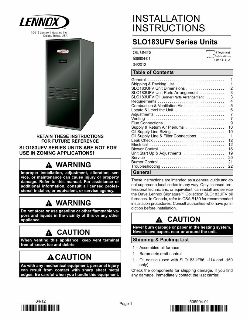
Table 1
Combustion Air Opening Dimensions
Model No. (2 openings required)
SLO183UFV−68/86& 101/114
10" X 20" (254 mm X 508 mm)
SLO183UFV−135/150 11" X 22" (279 mm X 559 mm)
This unit is approved for use on combustible flooring and for
clearances to combustible material as listed on unit rating
plate and in table 2. Unit service and accessibility clearances
take precedence over fire protection clearances.
Table 2
SLO183UFV Installation Clearances
Clearances inches (mm)
top of plenum & duct 2 (51)
plenum sides 3 (76)
sides 0 (0)
rear 0 (0)
front 4 (120)
flue pipe 6 (152)
NOTE − When service clearances are greater than fire
protection clearances, service clearances take prece-
dence.
Obtain a temperature rise within the range listed in table 8
in the Start-Up section of this manual.
When installed, furnace must be electrically grounded in
accordance with local codes or, in the absence of local
codes, with the current National Electric Code, ANSI/
NFPA No. 70, or Canadian Electric Code (CEC) if an exter-
nal electrical source is utilized.
Field wiring connection with unit must meet or exceed
specifications of type T wire and withstand a 63�F (17�C)
temperature rise.
If installing a programmable thermostat, use a type whichretains its memory in event of a power loss.When the fur-nace is used in conjunction with cooling units, it shall beinstalled in parallel with, or on the upstream side of, coolingunits to avoid condensation in the heating element. With aparallel flow arrangement, a damper (or other means to con-
trol the flow of air) shall be adequate to prevent chilled airfrom entering the furnace and, if manually operated, must beequipped with means to prevent operation of either unit, un-less damper is in the full �heat" or �cool" position.
WARNINGWhen an air conditioning unit is used in conjunc-tion with the furnace, the evaporator coil must beinstalled in the discharge (supply) air. Do not installan evaporator coil in the return air; excessive con-densation will occur within the furnace.

Page 5
Notice to Home Owner
This furnace is equipped with safety devices that protectyou and your property. If one or more of these devices isactivated, furnace operation will stop. If your home is leftunattended for an extended period of time, equipment op-eration must be checked periodically. If this is not possible,the water supply to the house should be shut off and thepipes should be drained. This will prevent problemsassociated with a NO HEAT condition (frozen pipes, etc.)
Combustion and Ventilation Air
Homes built with energy conservation in mind use tight
construction practices. These houses are sealed so well
that it becomes necessary to provide a means of bringing
in air from outside for combustion. Also, exhaust fans, ap-
pliance vents, chimneys and fireplaces force additional air
that could be used for combustion out of the house. Unless
outside air is brought into the home for combustion, nega-
tive pressure (pressure outside is greater than inside pres-
sure) will build to the point that a down draft can occur in the
furnace vent pipe or chimney. Combustion gases enter the
living space creating a potentially dangerous situation. Ne-
gative pressure may also interfere with proper combus-
tion, causing sooting within the heat exchanger.
The importance of the previous paragraph cannot be over-
stated. Users may inadvertently block fresh air intakes af-
ter installation.
In the absence of local codes concerning air for combus-
tion and ventilation, the following section outlines guide-
lines and recommends procedures for operating oil fur-
naces in a manner that ensures efficient and safe
operation. Special consideration must be given to combus-
tion air needs as well as requirements for exhaust vents
and oil piping.
Combustion Air Requirements
CAUTIONInsufficient combustion air can cause headaches,nausea, dizziness or asphyxiation. It will also causeexcess water in the heat exchanger resulting in rust-ing and premature heat exchanger failure. It can alsocause property damage.
All oil-fired appliances require air to be used for the com-
bustion process. If sufficient amounts of combustion air
are not available, the furnace or other appliance will oper-
ate in an inefficient and unsafe manner. Enough air must
be provided to meet the needs of all fuel-burning ap-
pliances, as well as appliances such as exhaust fans which
force air out of the home. When fireplaces, exhaust fans,
or clothes dryers are used at the same time as the furnace,
much more air is required to ensure proper combustion
and to prevent a down-draft situation. Insufficient amounts
of air also cause incomplete combustion which can result
in sooting. Requirements for providing air for combustion
and ventilation depend largely on whether the furnace is
installed in an unconfined or confined space.
Unconfined Space
An unconfined space is an area such as a basement or
large equipment room with a volume greater than 50 cubic
feet (1.4 cubic meters) per 1,000 Btu (293 W) per hour of
the combined input rating of all appliances installed in that
space. This space also includes adjacent rooms which are
not separated by a door. Though an area may appear to be
unconfined, it might be necessary to bring in outdoor air for
combustion if the structure does not provide enough air by
infiltration. If the furnace is located in a building of tight
construction with weather stripping and caulking around
the windows and doors, follow the procedures outlined for
using air from the outside for combustion and ventilation.
Confined Space
A confined space is an area with volume less than 50 cubic
feet (1.4 cubic meters) per 1,000 Btu (293 W) per hour of
the combined input rating of all appliances installed in that
space. This definition includes furnace closets or small
equipment rooms.
When the furnace is installed so that supply ducts carry air
circulated by the furnace to areas outside the space con-
taining the furnace, the return air must be handled by ducts
which are sealed to the furnace casing and which termi-
nate outside the space containing the furnace. This is es-
pecially important when the furnace is mounted on a plat-
form in a confined space such as a closet or small
equipment room. Even a small leak around the base of the
unit at the platform or at the return air duct connection can
cause a potentially dangerous negative pressure condi-
tion. Air for combustion and ventilation can be brought into
the confined space either from inside the building or from
outside.
Air from an Adjacent Space
If the confined space housing the furnace adjoins space
categorized as unconfined, air can be brought in by provid-
ing two permanent openings between the two spaces.
Each opening must have a minimum free area of 1 square
inch (6.4 square centimeters) per 1,000 Btu (293 W) per
hour of the total input rating of all fuel-fired equipment in the
confined space. Each opening must be at least 100 square
inches (614.5 square centimeters). One opening shall be
within 12" (305 mm) of the top of the enclosure and one
opening within 12" (305 mm) of the bottom (See figure 1).

Page 6
Equipment In Confined SpaceAll Air From Inside
Chimney orOil Vent
WaterHeater
Openings(To Adjacent Room)
Figure 1
NOTE−Each opening shall have a free area of at least 1 square inch(6.4 square centimeters) per 1,000 Btu (293 W) per hour of the totalinput rating of all equipment in the enclosure, but not less than 100square inches (614.5 square centimeters).
OilFurnace
Air from Outside
If air from outside is brought in for combustion and ventila-
tion, the confined space shall be provided with two perma-
nent openings. One opening shall be within 12" (305 mm)
of the top of the enclosure and one within 12" (305 mm) of
the bottom. These openings must communicate directly or
by ducts with the outdoors or spaces (crawl or attic) that
freely communicate with the outdoors or indirectly through
vertical ducts. Each opening shall have a minimum free
area of 1 square inch (6.4 square centimeters) per 4,000
Btu (1172 W) per hour of total input rating of all equipment
in the enclosure. (See figure 2.) When communicating with
the outdoors through horizontal ducts, each opening shall
have a minimum free area of 1 square inch (6.4 square
centimeters) per 2,000 Btu (586 W) per total input rating of
all equipment in the enclosure (See figure 3).
VentilationLouvers
(For unheatedcrawl space)
OutletAir
Equipment In Confined SpaceAll Air From Outside
(Inlet Air from Crawl Space and Outlet Air toVentilated Attic)
NOTE−The inlet and outlet air openings shall each have a free area of atleast one square inch (6.4 square centimeters) per 4,000 Btu (1172 W)per hour of the total input rating of all equipment in the enclosure.
Ventilation Louvers(Each End Of Attic)
WaterHeater
InletAir
Chimney orOil Vent
Figure 2
OilFurnace
When ducts are used, they shall be of the same cross−sec-
tional area as the free area of the openings to which they
connect. The minimum dimension of rectangular air ducts
shall be no less than 3" (76 mm). In calculating free area,
the blocking effect of louvers, grilles, or screens must be
considered. If the design and free area of protective cover-
ing is not known for calculating the size opening required, it
may be assumed that wood louvers will have 20 to 25 per-
cent free area and metal louvers and grilles will have 60 to
75 percent free area. Louvers and grilles must be fixed in
the open position or interlocked with the equipment so that
they are opened automatically during equipment opera-
tion.
Equipment In Confined SpaceAll Air From Outside
Outlet Air
Inlet Air
WaterHeater
ChimneyOr OilVent
Figure 3
NOTE−Each air duct opening shall have a free area of at least onesquare inch (6.4 square centimeters) per 2,000 Btu (586 W) per hour ofthe total input rating of all equipment in the enclosure. If the equipmentroom is located against an outside wall and the air openings communi-cate directly with the outdoors, each opening shall have a free area of atleast one square inch (6.4 square centimeters) per 4,000 Btu (1172 W)per hour of the total input rating of all other equipment in the enclosure.
OilFurnace
CAUTIONCombustion air openings in the front of the furnacemust be kept free of obstructions. Any obstructionwill cause improper burner operation and may re-sult in a fire hazard or injury.
CAUTIONThe barometric draft control shall be in the same at-mospheric pressure zone as the combustion air in-let to the furnace. Deviation from this practice willcause improper burner operation and may result ina fire hazard or injury.
Locate & Level the Unit
Set the unit in desired location keeping in mind the clear-ances listed in table 2. Also keep in mind oil supply connec-tions, electrical supply, flue connections and sufficient clear-ance for installing and servicing unit.

Page 7
Level the unit from side to side and from front to rear. If thefurnace is not level, place fireproof wedges or shims be-tween the low side of the furnace and the floor. Make surethe weight of the furnace is distributed evenly on all fourcorners. Strain on sides of cabinet causing cracking andpopping noises may occur if weight of furnace is not evenly
distributed.
Adjustments
Neither the nozzle setting nor the air adjustments are fac-tory set. The furnace is fire−tested and the limit control ischecked to make sure it functions properly; no factory set-tings are made. During installation, the furnace must be
�set up." The installing dealer/contractor must have anduse proper test equipment in order to correctly set up theoil furnace. Proper testing equipment is required to ensurecorrect operation of the unit. The use of test equipment isnow more critical than ever due to tighter tolerances need-ed to keep the furnace operating efficiently.
Among the test equipment for an oil furnace, the propercombustion test kit should contain the following:
� Draft gauge
� CO2 or O2 analyzer
� Smoke tester
� Pressure gauge
� High temperature thermometer
� Beckett T−501 or Z−2000 nozzle gauge
� Oil vacuum gauge
� Knowledge of proper test equipment operation
CAUTIONImproper nozzle and/or air adjustment of this unitmay result in sooting problems. Refer to the follow-ing section for correct adjustment procedures.
Adjusting the Nozzle
Proper adjustment of the nozzle assembly is critical. Beforethe flue pipe and oil lines are installed, the nozzle assemblymust be checked for proper depth and alignment. You mustremove the entire burner assembly (not just the nozzle) fromthe furnace to check the nozzle depth and alignment. Thesmaller sized firing nozzle has been factory−installed. This
should be verified by the installer. A larger nozzle has beenprovided in the bag assembly for use with SLO183UFV86,114 and 150 units. Inspect the spark transformer leads alsoto ensure they are still attached to the electrodes.
The burner assembly is attached to the vestibule panel bythree nuts. Slots are provided in the mounting flange for re-moving the burner assembly from the vestibule. Loosen
the nuts and turn the whole burner assembly clockwise(figure 4) to remove the entire burner assembly from thefurnace. There is adequate wire to remove the burner with-out disconnecting wires. Once removed, turn the burneraround in the vest panel area.
Figure 4
SLO183UFV Series Burner Removal
First, loosen three nuts whichattach burner to vest panel.
Next, rotate burner clockwiseon slots then pull toward you.
To correctly check and adjust the nozzle depth and align-
ment, use the Beckett T−501 or Z−2000 gauge.
To check the oil nozzle depth, insert the small end of the
gauge into the end of the cone and measure from the flat of
the end cone to the face of the nozzle. When nozzle depth
is correct, the tip of the nozzle should just touch the end of
the gauge. Refer to the illustration sheet provided with the
gauge. Note that the scale side of the gauge is not used for
this purpose. If necessary, loosen the escutcheon plate se-
curing screw and slide the entire nozzle assembly forward
or backward within the air tube (figure 5). Re−secure es-
cutcheon plate screw when adjustment is completed.
To check nozzle alignment, again insert the small end of
gauge into the end cone and measure the nozzle and
electrode alignment against the center lines marked on
the gauge (again refer to enclosed illustration sheet). If
the nozzle is not centered, but found to be too far left or
right, a new nozzle assembly will need to be ordered. Do
not attempt to adjust by bending the 90 degree elbow in
the oil line.
Take care to properly re−install burner assembly when
nozzle adjustment has been completed.
Figure 5
Beckett Oil Burner Nozzle Adjustment
Burner must be removed fromfurnace for this procedure. 1
2T−501 Gauge
Escutcheon Plate
To Adjust Nozzle1−Loosen escutcheon plate screw.
2−Slide entire nozzle/electrode assembly back and forth inside airtube until nozzle just touches gauge.

Page 8
Indoor Coil Placement
In cooling / heat pump applications, Lennox recommends
that the indoor coil be installed at least 4 inches above the top
of the furnace cabinet to allow proper airflow. If coil cabinet
does not provide proper clearance, use field−fabricated tran-
sition.
Venting
WARNINGCombustion air openings in front of the furnacemust be kept free of obstructions. Any obstructionwill cause improper burner operation and may re-sult in a fire hazard.
WARNINGThe barometric draft control shall be in the same at-mospheric pressure zone as the combustion air in-let to the furnace. Deviation from this practice willcause improper burner operation and may result ina fire hazard.
CAUTIONDo not store combustible materials near the furnaceor supply air ducts. The material (such as paint, mo-tor oil, gasoline, paint thinner, etc.) may ignite byspontaneous combustion creating a fire hazard.
WARNINGThis furnace is certified for use with type �L" vent.�B" vent must not be used with oil furnaces.
Prior to installation of unit, make a thorough inspection of the
chimney to determine whether repairs are necessary. Make
sure the chimney is properly constructed and sized ac-
cording to the requirements of the National Fire Protection
Association. The smallest dimensions of the chimney
should be at least equal to the diameter of the furnace vent
connector. Make sure the chimney will produce a steady
draft sufficient to remove all the products of combustion
from the furnace. A draft of at least .04" w.c. (9.9 Pa) is re-
quired during burner operation.
1 − Local building codes may have more stringent instal-
lation requirements and should be consulted before
installation of unit.
2 − The vent connector should be as short as possible to
do the job.
3 − The vent connector should not be smaller than the
outlet diameter of the vent outlet of the furnace.
4 − Pipe should be at least 24 gauge galvanized.
5 − Single wall vent pipe should not run outside or through
any unconditioned space.
6 − Chimney should extend 3 feet (0.9 m) above highest
point where the vent passes through the roof, and 2
feet (0.6 m) higher than any portion of a building within
a horizontal distance of 10 feet (3 m).
7 − The vent must not pass through a floor or ceiling.
Clearances to single wall vent pipe should be no less
than 6" (152 mm); more if local codes require it.
8 − The vent may pass through a wall where provisions
have been made for a thimble as specified in the Stan-
dards of the National Board of Fire Underwriters. See
figure 4.
Wall Thimble
Figure 4
Thimble
Vent PipeCombustible
Wall
9 − The vent pipe should slope upward toward the chim-
ney on horizontal run at least 1/4 inch (6 mm) to the
foot (0.3 m) and should be supported by something
other than the furnace, such as isolation hangers.
10 − Extend the vent pipe into the chimney so that it is flush
with the inside of the chimney liner. Seal the joint be-
tween the pipe and the liner.
11 − The furnace shall be connected to either a factory−
built chimney or vent which complies with a recog-
nized standard, or to a masonry or concrete chimney
which has been lined with a material acceptable to the
authority having jurisdiction.
12 − When two or more appliances vent into a common
vent, the area of the common vent should not be less
than the area of the largest vent or vent connection
plus 50% of the area of the additional vent or vent con-
nection. Chimney must be able to sufficiently vent all
appliances operating at the same time.

Page 9
Factory−Built Chimney
Figure 5
CondensateDrain
Barometric DraftControl*
(in either location)
Factory−Built
Chimney
*Barometric draft control may be installed in either vertical or hor-izontal section of flue pipe no less than 12" and no more than 18"from furnace flue outlet.
Masonry Chimney
BarometricDraft
Control*(in eitherlocation)
Clean Out
Liner
MasonryChimney
Figure 6
*Barometric draft control may be installed in either vertical or hor-izontal section of flue pipe no less than 12" and no more than 18"from furnace flue outlet.
13 − The vent pipe shall not be connected to a chimney
vent serving a solid fuel appliance or any mechanical
draft system.
14 − All unused chimney openings should be closed.
15 − All vent pipe run through unconditioned areas or out-
side shall be constructed of factory−built chimney sec-
tions. See figure 5.
16 − Where condensation of vent gas is apparent, the vent
should be repaired or replaced. Accumulation of con-
densation in the vent is unacceptable.
17 − Vent connectors serving this appliance shall not be
connected into any portion of mechanical draft sys-
tems operating under positive pressure.
18 − Keep the area around the vent terminal free of snow,
ice and debris.
NOTE − If vent pipe needs to exit from side of cabinet,
use the pilot hole (located on either side of the unit) to
cut a 6" (152 mm) round hole. Attach finishing plate
(provided) with four sheet metal screws to cover rough
edges.
Removal of Unit from Common Venting System
In the event that an existing furnace is removed from a
venting system commonly run with separate appliances,
the venting system is likely to be too large to properly vent
the remaining attached appliances. The following test
should be conducted while each appliance is in operation
and the other appliances not in operation remain con-
nected to the common venting system. If venting system
has been installed improperly, the system must be cor-
rected as outlined in the previous section.
1 − Seal any unused openings in the common ventingsystem.
2 − Visually inspect venting system for proper size andhorizontal pitch and determine there is no blockage orrestriction, leakage, corrosion or other deficiencieswhich could cause an unsafe condition.
3 − Insofar as is practical, close all building doors and win-dows and all doors between the space in which the ap-pliances remaining connected to the common ventingsystem are located and other spaces of the building.Turn on clothes dryers and any appliances not con-nected to the common venting system. Turn on any
exhaust fans, such as range hoods and bathroom ex-hausts, so they will operate at maximum speed. Donot operate a summer exhaust fan. Close fireplacedampers.
4 − Following the lighting instruction on the unit, place the
appliance being inspected in operation. Adjust ther-
mostat so appliance will operate continuously.
5 − Test for spillage using a draft gauge.
6 − After it has been determined that each appliance re-
maining connected to the common venting systemproperly vents when tested as outlined above, returndoors, windows, exhaust fans, fireplace dampers andany other fuel burning appliance to its previous condi-tion of use.
7 − If improper venting is observed during any of theabove tests, the common venting system must be cor-rected.
Flue Connections
IMPORTANTWhen flue pipe is installed at less than minimumclearance listed in table 2, radiation shields must beinstalled. See figure 6.
Use 24 gauge or heavier galvanized smoke pipe and fit-tings to connect the furnace to the vent. Connect flue pipeto chimney using the least number of elbows and anglespossible. Flue pipe or vent connector must be inserted intobut not beyond the inside surface of the chimney flue. No
reduction in diameter of flue pipe is acceptable. It is best to

Page 10
have flue pipe as short and direct as possible. Where twoor more appliances vent into a common flue, the area ofthe common flue should be at least equal to the area of thelargest flue or vent connector, plus 50% of the area of anyadditional flues or vent connectors. Install a barometricdraft control (provided) and flue pipe according to instruc-
tions packed with control.
Inspect flue pipe annually. Clean soot or ash from flue pipe,
if necessary. If pipe is rusted, replace.
Barometric Draft Control Installation
Install the provided barometric draft control in the flue pipe
at least 12 inches beyond the furnace flue outlet to pro-
vide space for flue gas sampling. The barometric draft con-
trol may be installed in either vertical or horizontal sections
of the flue pipe; however, it should be positioned no more
than 18" beyond the furnace flue outlet. Follow the instruc-
tions packed with the barometric draft control.
Alternate Side Flue Connections
The vent pipe may exit the top or sides of the cabinet. Ahole is provided in the top cap for top exit. For side exit, lo-cate the center hole punched in the side of the cabinet. Seeunit dimensions on page 2. Using it as the center point,
cut a 6 inch (152 mm) round hole in the cabinet’s side.Install the barometric draft control within 18 inches ofthe furnace flue outlet. Attach the provided finishingplate to cover rough edges.
ÏÏÏÏÏÏÏÏÏÏÏÏÏÏÏÏÏÏÏÏÏÏÏÏÏÏÏÏÏÏÏÏÏÏÏÏÏÏÏÏÏÏÏÏÏÏÏÏÏÏÏÏÏÏÏÏÏÏÏÏÏÏÏÏ
ÏÏÏÏÏÏÏÏÏÏÏÏÏÏÏÏÏÏÏÏÏÏÏÏÏÏÏÏÏÏÏÏÏÏÏÏÏÏÏÏÏÏÏÏÏÏÏÏÏÏÏÏÏÏÏÏÏÏÏÏÏÏÏÏ
1" (25 mm) min
Figure 6
COMBUSTIBLEMATERIAL
Radiation Shield Installation
SLO183UFV UNIT(TOP)
SLO183UFV UNIT(FRONT)
RADIATIONSHIELDS
FLUEPIPE
UNITCABINET
NOTE 1−Radiation shields must be constructed of 24 gauge sheetmetal minimum.
NOTE 2−Radiation shields required when A is less than 9" (229 mm).
NOTE 3−Radiation shields should extend from the top of the unit tothe top of the flue pipe.
NON−COMBUSTIBLE
SPACERS
RADIATION SHIELDS (SEE NOTE 1)
7" (178mm) min
12" (305 mm) min
AA
BSEE
NOTE3
SEENOTE 2
Supply & Return Air Plenums
Secure return air plenum to unit using sheet metal screws.
NOTE − The following are suggested procedures that should
be followed when installing the supply air plenum.
1. Use sealing strips of fiberglass.
2. In all cases, the plenum should be secured to furnace orevaporator cabinet with sheet metal screws.
3. Install supply and return air ducts as desired.
Oil Supply Line Sizing
Ensure that the restrictions of the piping system, plus anylift involved, do not exceed the capability of the oil pump.Use the following guidelines when determining whether touse a single−or two−stage oil pump.
One−Pipe SystemWhen using a one−pipe system (see figure 7), even with
the oil tank that is above the burner and a vacuum of 6"(152 mm) Hg or less, a single−stage fuel pump with a sup-ply line and no return line should be adequate.
Manual bleeding of the fuel pump is required on initial startup. Failure to bleed air from the oil pump could result in anair lock/oil starvation condition.
NOTE − As an extra precaution, cycle heating on and off
ten times after bleeding air from the oil pump. This will elim-
inate air in the gun assembly.
Figure 7
Oil Piping − One-Pipe System
ÓÓÓÓÓÓÓÓÓÓÓÓÓÓÓÓÓÓÓÓÓÓÓÓÓÓÓÓÓÓÓÓÓÓÓÓÓÓÓÓÓÓÓÓÓÓÓÓÓÓÓÓÓÓÓÓÓÓÓÓÓÓÓÓÓÓÓÓÓÓÓÓÓÓÓÓÓÓÓÓÓÓÓÓÓÓÓÓÓÓÓÓÓÓÓÓÓÓÓÓÓÓÓÓÓÓÓÓÓÓÓÓÓÓÓÓÓÓÓÓ
AIR VENT
FILL PIPE
OIL
TANK
FUEL PUMPAUXFILTER
SHUT−OFFVALVE
8 ft (2.4 m)
Maximum
One Pipe Lift
To determine the correct tubing size for piping, refer to table 3.
Table 3
One−Pipe Oil Line Sizing
Line Length Pipe Diameter (OD Tubing)
0−50’ (15 m) 3/8" (10 mm)
51−100’ (15 m) 1/2" (12 mm)
Two−Pipe SystemWhen using a two−pipe system (see figure 8) with the oiltank below the level of the burner, use a single−stage fuelpump in lift conditions of up to 10 feet (3 m) and/or a vacu-
um of 10" (254 mm) Hg or less. Use a two−stage fuel pump

Page 11
when lift exceeds 10 feet (3 m) and/or a vacuum of 10" (254mm) Hg to 15" (381 mm) Hg. Both conditions require theuse of a two−pipe system, which consists of a return line
that purges the fuel pump of air by returning it to the tank.To determine the run and lift for piping, refer to table 5 .
Table 4Fuel Pump Usage
Pump Piping Application Maximum Lift (vacuum)
Single−Stage PumpOne−Pipe System 8 ft. (6" Hg vacuum)
Two−Pipe System 10 ft. (12" Hg vacuum)
Two−Stage Pump Two−Pipe System10 ft. or greater
(12" to 17" Hg vacuum)
Use continuous lengths of heavy wall copper tubing orsteel pipe for oil supply pipe. Install oil supply pipe underfloor or near walls to protect it from damage. Avoid runningpipes along joists or reverberating surfaces. Always useflare fittings. All fittings must be accessible. Do not usecompression fittings.
Figure 8
ÓÓÓÓÓÓÓÓÓÓÓÓÓÓÓÓÓÓÓÓÓÓÓÓÓÓÓÓÓÓÓÓÓÓÓÓÓÓÓÓÓÓÓÓÓÓÓÓÓÓÓÓÓÓÓÓÓÓÓÓÓÓÓÓÓÓÓÓÓÓ
RETURNPIPE
OIL
TANK
RETURNPIPE
H
3"−4"
(76 mm −102 mm)
R
outside tank fuel pump above bottom of tank.
Oil Piping − Two-Pipe SystemAIR VENT
FILL PIPEFUEL PUMP
AUXFILTER
INLET
IMPORTANTBoth oil supply and return pipes must be sub-merged in oil in the supply tank.
Table 5
Two−Pipe Maximum Pipe Length (H + R) 3450 RPM − 3 GPH (11.4 LPH)
Lift �H" ft (m)
Single−Stage
Two−Stage
Single−Stage
Two−Stage
3/8" (10 mm) ODTubing − ft (m)
1/2" (12 mm) ODTubing
0’ (0.0) 84 (25.6) 93 (28.3) 100 (30.5) 100 (30.5)
2’ (0.6) 73 (22.3) 85 (25.9) 100 (30.5) 100 (30.5)
4’ (1.2) 63 (19.2) 77 (23.5) 100 (30.5) 100 (30.5)
6 ’ (1.8) 52 (15.8) 69 (21.0) 100 (30.5) 100 (30.5)
8’ (2.4) 42 (12.8) 60 (18.3) 100 (30.5) 100 (30.5)
10’ (3.0) 31 (9.4) 52 (15.9) 100 (30.5) 100 (30.5)
12’ (3.7) 21 (6.4) 44 (13.4) 83 (25.3) 100 (30.5)
14’ (4.3) −−− 36 (11.0) 41 (12.5) 100 (30.5)
16’ (4.9) −−− 27 (8.2) −−− 100 (30.5)
18’ (5.5) −−− −−− −−− 76 (23.2)
Oil Supply Line & Filter Connections
One−Pipe Systems
CAUTIONDo not install the bypass plug into the pump on one−pipe systems.
The burner is shipped with a single−stage fuel pump set forone−pipe operation. For one−pipe systems, the oil supplypipe is connected to the inlet tap on the pump. A one−pipesystem should only be used where there is gravity oil flowto the pump or there is no more than 8 ft. of vertical lift (or 6in. Hg) from the oil tank to the fuel pump. 1 − Connect the inlet pipe to the pump inlet. Start the burner. 2 − Turn the bleed valve one turn counterclockwise. 3 − Bleed the unit until all air bubbles disappear.
NOTE − Hurried bleeding will prevent the unit from op-erating properly.
4 − If necessary, put GeniSys� primary control into its4−minute pump priming mode. Refer to table 10.
5 − Tighten the bleed valve securely.
Two−Pipe SystemsIf the installation requires a two−pipe operation, install thebypass plug included in the bag which is attached to the
pump. To convert the pump, install the bypass plug accord-ing to the provided pump instructions. Notice in the two-
Page 12
pipe system the return pipe must terminate in the tank 3"(76 mm) to 4" (102 mm) above the supply inlet. Ensure thereturn pipe terminates at the correct measurement or airmay escape into the system. This could result in loss ofprime.
NOTE− If using an outside tank in cold climates a number
one fuel or an oil treatment is strongly recommended.
1. Remove 1/4" plug from return port.
2. Insert bypass plug and tighten it (see figure 8).
3. Attach the return and inlet pipes. Start the burner. Airbleeding is automatic.
NOTE − If a faster bleed is necessary, open the bleedvalve.
4. The return pipe must terminate 3" to 4" above the sup-ply pipe inlet (see figure 8).
NOTE − If the return pipe does not terminate where itshould, air may enter the system, and prime may belost.
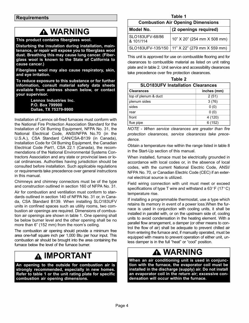
An oil filter is required for all models. Install filter insidethe building between the tank shut-off valve and the burn-er. Locate filter close to burner for easy maintenance.Table 6 lists the filters for the SLO183UFV furnace.
Table 6
Oil Filters Cat. No.
10 micron filter (no mounting bracket) 81P89
10 micron filter (mounting bracket) 53P92
10 micron replacement cartridge for filter, 45 gph 53P93
Filter restriction indicator gauge 53P90
Consult burner manufacturer’s instructions packaged withunit for further details concerning oil supply pipe connec-
tions.
Leak Check
After oil piping is completed, carefully check all piping con-nections (factory and field) for oil leaks.
Oil Pipe Heater (Optional)A heater for the oil pipe is available for applications that arelocated in cold climates. The heater warms the oil pipe toassist the initial start−up.
Electrical
All wiring must conform to the National Electric Code
(NEC), or Canadian Electric Code (CEC) and any local
codes. Refer to figure 7 for typical unit wiring diagram. See
figures and for field wiring. Refer to figure 11 for terminal
designations on blower control.
1 − Refer to appliance rating plate for proper fuse size.
2 − Install room thermostat and make wire connections tothe fan control board. Avoid installing thermostat on anoutside wall or where it can be affected by radiant heat.Set the adjustable heat anticipator on thermostat ac-cording to the wiring diagram sticker provided on unit.
3 − Install a separate fused disconnect switch near unit sopower can be shut off for servicing.
4 − Complete line voltage wiring from disconnect switchnear unit to make-up box.
NOTE − An equipment ground screw is provided. Referto unit wiring diagram. Ground unit using a suitableground wire.
5 − A 24V dehumidistat or ComfortSense® 7000 input(from terminal D) can be connected to the reverse−act-ing HUM terminal on the A54 blower control. See fig-ure 11.
WARNINGRun 24V Class II wiring only through specified lowvoltage opening. Run line voltage wiring onlythrough specified high voltage opening. Do notcombine voltage in one opening.
CAUTIONUSE COPPER CONDUCTORS ONLY.
IMPORTANTIf using a programmable thermostat, be sure to usea type of thermostat that retains its memory in eventof a power loss.

Page 13
Figure 7
Typical SLO183UFV Wiring Diagram
OIL DELAY
A15
A54
9
1
ST9103A
Page 14
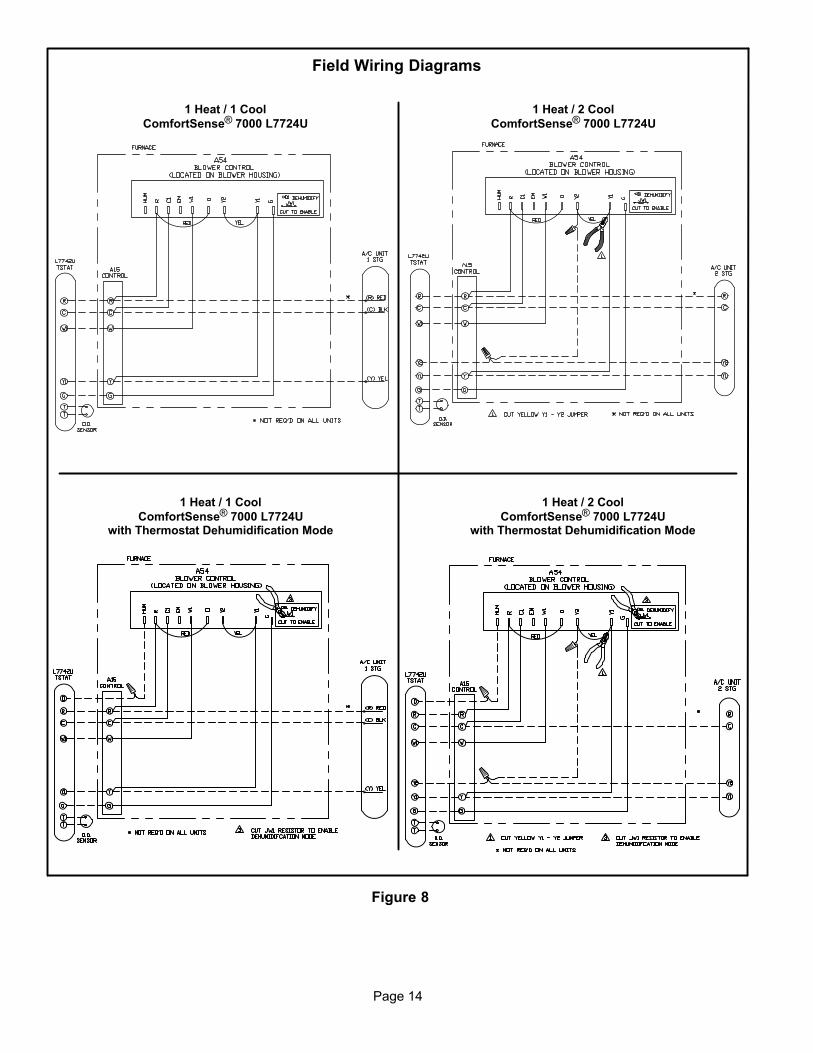
Figure 8
Field Wiring Diagrams
1 Heat / 1 Cool
ComfortSense® 7000 L7724U
1 Heat / 2 Cool
ComfortSense® 7000 L7724U
1 Heat / 1 Cool
ComfortSense® 7000 L7724Uwith Thermostat Dehumidification Mode
1 Heat / 2 Cool
ComfortSense® 7000 L7724Uwith Thermostat Dehumidification Mode

Page 15
Figure 9
Field Wiring Diagrams (Continued)
Dual Fuel Single−Stage Heat Pump
ComfortSense® 7000 L7724Uwith Dual Fuel Control Mode
Dual Fuel Two−Stage Heat Pump
ComfortSense® 7000 L7724Uwith Dual Fuel Control Mode
Dual Fuel Two−Stage Heat Pump
ComfortSense® 7000 L7724Uwith Dual Fuel Control Mode
and Thermostat Dehumidification Mode

Page 16
Blower Control (A54)
WARNINGElectric shock hazard. Can causeinjury or death. Before attempting toperform any service or maintenance,turn the electrical power to unit OFF atdisconnect switch(es). Unit may havemultiple power supplies.
SLO183UFV units are equipped with a variable speedblower motor which is capable of maintaining a specifiedCFM throughout the external static range. Harmony zonecontrols cannot be used with this furnace since the ECMmotor is not programmed for variable speed operation.The blower motor is controlled by jumper selections madeon the A54 blower control. Jumpers are available to selectboth heating and cooling blower speeds, as well as adjust-ment rates for cooling blower speeds and a test mode.Blower control settings and operation are described in thissection.
The units are factory−set for nominal airflow for each mod-el. Figure 11 shows the blower control. Use table 7 to deter-mine the correct air volume for operation in heat and coolmode.
Read this section thoroughly before adjusting the jumpersto obtain the appropriate blower speed.
To change jumper positions, gently pull the jumper off thepins and re−position it across the pins that will give the desiredblower speed. The following section outlines the differentjumper selections available and conditions associated witheach one (see figure 11).
IMPORTANTThe unit is not designed for and will not work withthe Harmony zone control system.
COOL (single-stage systems)The COOL jumper is used to determine the CFM duringcooling operation. This jumper selection is activated forcooling when Y1 is energized. A factory−installed jumperfrom Y1 to Y2 allows single−stage cooling.
The blower motor runs at 82% CFM for the first 7−1/2 min-utes of each cooling demand to allow for greater humidityremoval and to conserve energy. If, after 7−1/2 minutes,the Y demand is not met, 100% CFM is supplied until the
demand is satisfied.
OFFCALL
100%
82%
Y
60sec
7.5 minutes
82%
y
Y − Cool Demand Present
y − Cool Demand Satisfied
When the demand for cool is met, the blower ramps downto 82% CFM for 60 seconds, then turns off.
COOL (two-stage systems)
This unit is factory−wired for single−stage cooling. Fortwo−stage cooling operation, you must cut the jumperwire from Y1 to Y2 on the A54 blower control. Cut thejumper close to the Y1 terminal to allow a pigtail connectionwith the remaining wire from the Y2 terminal and a wireconnected to the Y2 terminal of the two−stage thermostat.Refer to field wiring diagrams.
A thermostat call for first-stage cooling closes the R to Y1circuit on the A54 blower control. The blower motor runs at57% CFM for the first 7−1/2 minutes of the 1st−stage cool-ing demand. After 7−1/2 minutes, the blower motor runs at70% CFM until the first−stage demand is satisfied.
OFFCALL
100%
70%
57%
Y17−1/2 minutes
60sec
y2/Y1
Y1 − 1st−stage COOL Demand Present
y1 − 1st−stage COOL Demand Satisfied
Y2 − 2nd−stage COOL Demand Present
y2 − 2nd−stage COOL Demand Satisfied
Y1/Y2
70%
57%
y1
y1
OFF
60sec
If first−stage cooling does not satisfy the demand, the ther-mostat calls for 2nd-stage cooling, closing the R to Y2 cir-cuit on the A54 blower control. The blower motor ramps upto 100% CFM.
When the Y2 demand is met, the blower ramps down to Y1at 70% CFM until Y1 is met, and ramps down to 57% CFMfor 1 minute, then turns off.
Heat Pump
IMPORTANTFor heat pump operation, cut the jumper between Rand O near the R terminal of A54 and connect thepigtail to the thermostat O wire (A54 board �O" tothermostat �O"). See figure 10.
In heat pump mode, a call for heat pump operation followsthe same sequence as a call for cooling, with the exceptionthat there is a 30−second blower ramp−up to blower CFM.

Page 17
Figure 10
A54
A15
Heat Pump Applications
Clip red jumper from R to Oclose to R terminal.
Make pigtail connection and run wire fromterminal O to O terminal onthermostat.
To blowermotor
ADJUST
The ADJUST pins affect blower motor speed during cool-ing operation only. The ADJUST feature allows the motor
to run at normal speed, approximately 15% higher thannormal speed, or 15% lower than normal speed during thecooling mode. Table 7 gives three rows�NORM, (+), and(–) with their respective CFM volumes. Notice that the nor-mal �NORM" adjustment setting for cool speed position Cin table 7 is 800 CFM. The �(+)" adjustment setting for thatposition is 920 CFM (115% of 800 CFM) and the �(–)" ad-
justment setting is 680 CFM (85% of 800 CFM). After theadjustment setting has been determined, choose the re-maining speed settings from those offered in the table inthat row.
HEATThe unit is factory−set to run at the middle of heating riserange as shown on the unit rating plate. The jumper on thetap marked HEAT must remain in the position given in table7.
The HEAT jumper is used to determine CFM during heat-ing operation only. These jumper selections are activatedonly when W1 is energized.
During the heat ON delay, the blower runs at 13% CFM forthe first minute, 50% CFM for the second minute, and fullCFM after two minutes.
OFFCALL
100%
82%
50%
13%
W60sec
60sec
210 secondsw
W − Heat Demand Present
w − Heat Demand Satisfied
When the demand for heat is met, the blower ramps downto 82% CFM for 3−1/2 minutes, then turns off.
TEST
The TEST pin is available to bypass the blower control andrun the motor at approximately 70% to make sure that themotor is operational. This is used mainly in troubleshoot-ing. The G terminal must be energized for the motor to run.
CFM LED
The CFM LED located on the blower control flashes onetime per 100 cfm to indicate selected blower speed. Forexample, if the unit is operating at 1000 CFM, the CFMLED will flash 10 times.
At times, the light may appear to flicker or glow. This takesplace when the control is communicating with the motorbetween cycles. This is normal operation.
After the CFM for each application has been determined,the jumper settings must be adjusted to reflect those givenin table 7. From the table, determine which row most close-ly matches the desired CFM. Once a specific row has beenchosen (+, NORMal, or −), CFM volumes from other rowscannot be used. Below are descriptions of the jumperselections.
The variable speed motor slowly ramps up to and downfrom the selected air flow during both cooling and heatingdemand. This minimizes noise and eliminates the initialblast of air when the blower is initially energized.
Continuous Fan
When the thermostat is set for �Continuous Fan" operationand there is no demand for heating or cooling, the blowercontrol will provide 50% of the COOL CFM selected.
OFFCALL
50%
G g
G − Fan switch ON
g − Fan switch OFF
NOTE − With the proper thermostat and subbase, continu-
ous blower operation is possible by closing the R to G cir-
cuit.
Dehumidification
The A54 blower control (see figure 11) includes a HUM ter-
minal which provides for connection of a humidistat. TheJW1 jumper on the blower control must be cut to activatethe HUM terminal. The humidistat must be wired to openon humidity rise. When the dehumidification circuit is used,the variable speed motor will reduce the selected air flowrate by 18% when humidity levels are high. An LED (D1)
lights when the blower is operating in the dehumidificationmode.
Humidification
Terminals are provided on the A15 control for 120 volt out-put to operate a humidifier. The �HUM" terminal is ener-gized when there is a call for heat. See figure 13.
Indoor Air Quality (IAQ) Accessory
An EAC terminal is provided on the A15 control for 120 voltoutput to an indoor air quality accessory. The EAC terminalis energized when there is a call for heat, cool, or continu-ous blower. See figure 13.
Page 18
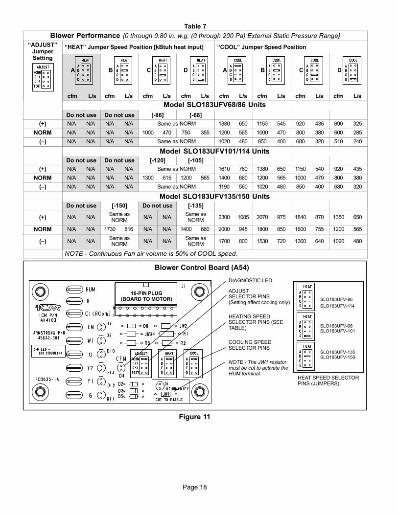
Table 7
Blower Performance {0 through 0.80 in. w.g. (0 through 200 Pa) External Static Pressure Range}
�ADJUST"JumperSetting
�HEAT" Jumper Speed Position [kBtuh heat input] �COOL" Jumper Speed Position
A B C D A B C D
cfm L/s cfm L/s cfm L/s cfm L/s cfm L/s cfm L/s cfm L/s cfm L/s
Model SLO183UFV68/86 Units
Do not use Do not use [−86] [−68]
(+) N/A N/A N/A N/A Same as NORM 1380 650 1150 545 920 435 690 325
NORM N/A N/A N/A N/A 1000 470 750 355 1200 565 1000 470 800 380 600 285
(–) N/A N/A N/A N/A Same as NORM 1020 480 850 400 680 320 510 240
Model SLO183UFV101/114 Units
Do not use Do not use [−120] [−105]
(+) N/A N/A N/A N/A Same as NORM 1610 760 1380 650 1150 540 920 435
NORM N/A N/A N/A N/A 1300 615 1200 565 1400 660 1200 565 1000 470 800 380
(–) N/A N/A N/A N/A Same as NORM 1190 560 1020 480 850 400 680 320
Model SLO183UFV135/150 Units
Do not use [−150] Do not use [−135]
(+) N/A N/ASame asNORM
N/A N/ASame asNORM
2300 1085 2070 975 1840 870 1380 650
NORM N/A N/A 1730 816 N/A N/A 1400 660 2000 945 1800 850 1600 755 1200 565
(–) N/A N/ASame asNORM
N/A N/ASame asNORM
1700 800 1530 720 1360 640 1020 480
NOTE − Continuous Fan air volume is 50% of COOL speed.
Blower Control Board (A54)
16−PIN PLUG(BOARD TO MOTOR)
DIAGNOSTIC LED
ADJUSTSELECTOR PINS(Setting affect cooling only)
HEATING SPEEDSELECTOR PINS (SEETABLE)
COOLING SPEEDSELECTOR PINS
NOTE − The JW1 resistormust be cut to activate theHUM terminal.
Figure 11
SLO183UFV−86
SLO183UFV−114
SLO183UFV−68SLO183UFV−101
SLO183UFV−135SLO183UFV−150
HEAT SPEED SELECTORPINS (JUMPERS)
Page 19
Unit Start−Up & Adjustments
Before starting unit, make sure the oil tank is adequatelyfilled with clean No. 1 or No. 2 furnace oil.
NOTE − Water, rust or other contaminants in oil supply sys-
tem will cause malfunction and failure of the internal parts
of the fuel pump.
CAUTIONNever burn garbage or paper in the heating system.Never leave papers near or around the unit.
CAUTIONBlower access door must be in place before start-up.
Burner Start−Up
1 − Set thermostat for heating demand and turn on electri-
cal supply to unit.
2 − Open all shut−off valves in the oil supply line to the
burner.
3 − While the ignition is on, press and release the reset
button on the burner control (hold 1/2 second or less).
4 − Bleed the pump until all froth and bubbles are purged.
The bleed port is located on the bottom of the fuel
pump. To bleed, attach a clear plastic hose over the
vent plug. Loosen the plug and catch the oil in an
empty container. Tighten the plug when all the air has
been purged.
NOTE − A two−line fuel system will normally bleed itself
by forcing air back to the tank through the return line.
This type of bleeding procedure is not necessary.
5 − If burner fails to start within the set time, the burner
control will lock out operation. Press the reset button
to reset the control as in step 3. See figure on page 3
for burner parts arrangement.
CAUTIONDo not push the reset button on the primary controlmore than one time.
6 − Repeat steps 4 and 5, if necessary, until pump is fully
primed and oil is free of bubbles. Then, terminate the
call for heat. The burner control will resume normal
operation
Fuel Pump Pressure Adjustment
Measure fuel pump pressure with unit off. Attach pressure
gauge to pump outlet. Turn unit on and check pressure and
compare to table 9. Adjust if necessary.
Temperature Rise Adjustment
To measure temperature rise, place plenum thermometers
in warm air and return air plenums. Locate thermometer in
warm air plenum where thermometer will not �see" the heat
exchanger to prevent it from picking up radiant heat. Set
thermostat to its highest setting to start unit. After plenum
thermometers have reached their highest and steadiest
readings, subtract the readings. The difference in temper-
atures in the supply and return air plenums should approxi-
mate the temperatures listed in table 8 and on the ap-
pliance rating plate.
If the temperature rise is not within the range listed, check
the following items:
� Make sure that properly sized nozzle has beenused (table 9).
� Make sure that fuel pump pressure is correct.� If furnace is in cutback mode, check for:
Dirty filters,Dirty indoor coil,Restricted ducts, closed registers, etc.
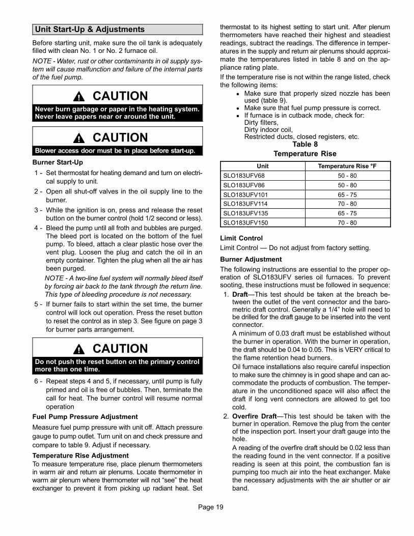
Table 8
Temperature Rise
Unit Temperature Rise °F
SLO183UFV68 50 − 80
SLO183UFV86 50 − 80
SLO183UFV101 65 − 75
SLO183UFV114 70 − 80
SLO183UFV135 65 − 75
SLO183UFV150 70 − 80
Limit Control
Limit Control � Do not adjust from factory setting.
Burner Adjustment
The following instructions are essential to the proper op-eration of SLO183UFV series oil furnaces. To preventsooting, these instructions must be followed in sequence:
1. Draft�This test should be taken at the breach be-tween the outlet of the vent connector and the baro-metric draft control. Generally a 1/4" hole will need tobe drilled for the draft gauge to be inserted into the ventconnector.
A minimum of 0.03 draft must be established without
the burner in operation. With the burner in operation,
the draft should be 0.04 to 0.05. This is VERY critical to
the flame retention head burners.
Oil furnace installations also require careful inspection
to make sure the chimney is in good shape and can ac-
commodate the products of combustion. The temper-
ature in the unconditioned space will also affect the
draft if long vent connectors are allowed to get too
cold.
2. Overfire Draft�This test should be taken with theburner in operation. Remove the plug from the centerof the inspection port. Insert your draft gauge into thehole.
A reading of the overfire draft should be 0.02 less than
the reading found in the vent connector. If a positive
reading is seen at this point, the combustion fan is
pumping too much air into the heat exchanger. Make
the necessary adjustments with the air shutter or air
band.

Page 20
Table 9
Burner Specifications
UnitBurnerNumber
BeckettSpec. No.
BeckettAir TubePart No.
InputRating
BTU/HR
Nozzle Size,Spray, Angle, &
Pattern
PumpPressure
HeadInsertionLength
StaticPlate
Diameter
SLO183UFV−68/86 100591−04 ARM−2007AF46XZT
HS68,000 0.50 gph x 80° B 100 F0 4−3/4 2−3/4
SLO183UFV−68/86 100591−04 ARM−2007AF46XTH
S86,000 0.50 gph x 80° B 100 F0 4−3/4 2−3/4
SLO183UFV−101/114 100591−05 ARM2008AF46XNH
S101,000 0.65gph X 80° B 140 F3 4−3/4 2−3/4
SLO183UFV−101/114 100591−05 ARM2008AF46XNH
S114,000 *0.65gph X 80° B 140 F3 4−3/4 2−3/4
SLO183UFV−135/150 100591−06 ARM2009AF46WPH
S135,000 1.00gph x 80° 140 F4 4−3/4 3−3/8
SLO183UFV−135/150 100591−06 ARM2009AF46WPH
S150,000 *1.00gph X 80° B 140 F4 4−3/4 3−3/8
*Nozzle must be field−installed for conversion to higher heating input.NOTE − All nozzles are Delavan brand.
Air Band(Secondary)
Air Shutter / Band Adjustment
Loosen this screwto adjust air band.
Air Shutter
Air Band
Figure 123. Smoke Test�The smoke test should be taken at the
hole drilled in step 1.
Using a smoke test gun, adjust the air so that you will
have just a trace (between 0 and #1) of smoke. If the
burner is producing more than #1 smoke, adjust the air
shutter (primary) and air band (secondary) to reduce
the smoke. See figure 12. To adjust the air shutter,
loosen the top screw on the air shutter (and lower
screw, if necessary). Then, rotate the shutter until the
desired smoke level is achieved. If smoke cannot be
reduced to the desired level by moving the air shutter,
adjust the air band to increase the air. To adjust the air
band, loosen the air band screw and rotate the
band.This is the starting point. Do not stop here.
4. CO2 Test�Again, take this sample at the vent pipe.
With the unit firing at a trace of smoke, take a sample of
the CO2. From the results of this test, a �window of op-
eration" will be determined. This window of operation
establishes some tolerance. The tolerance the install-
er builds in provides room within the set-up for those
things which might affect combustion. Those things
which might affect combustion can then do so without
causing the unit to start sooting/smoking. Things
which might affect combustion include a nozzle going
bad, draft that changes during different climatic condi-
tions, dirty oil, dirt obstructing the air inlet, etc.
To build in a �window of operation," set up the burner to
be 2% less in CO2. For example, if you find a reading of
12% CO2, adjust the air shutter (and air band, if neces-
sary) to increase the air and drop the CO2 to 10%.
5. Retest the Smoke�With a drop in the CO2 and in-crease in the air you should see that the smoke has re-turned to 0.
6. Retest the Overfire Draft�This test serves to con-firm that you have not increased the air too much.Again you do not want a positive pressure at the testport. It should still be 0.02 less than the draft pressurereading taken at the breach. You may need to increasethe stack draft by adjusting the barometric draft con-trol.
7. Stack Temperature�Take a stack temperature read-ing in the vent pipe. Subtract the room air temperaturefrom the stack temperature. This will give you the netstack temperature. Use the efficiency charts providedin most CO2 analyzers to determine furnace efficiency.
8. When the proper combustion and smoke readingshave been achieved, re−tighten the air shutterscrew(s) and air band screw.
Page 21
Service
CAUTIONDo not tamper with unit controls. Call your qualifiedservice technician.
Servicing the Air Filter
NOTE − Under no circumstances should the access panels
to the blower compartment be left off or left partially open.
Throw-Away Type Filters�Check filters monthly and re-place when necessary to assure proper furnace operation.Replace filters with like kind and size filters.
Reusable Type Filters�Filters should be checkedmonthly and cleaned when necessary to assure proper fur-nace operation. Use warm water and a mild detergent. Re-
place filter when dry. Permanent filters supplied withSLO183UFV furnaces do not require oiling after cleaning.Examine filter label for any for special instructions that mayapply.
Servicing the Blower
Blower motor is prelubricated and sealed for extended op-eration. No further lubrication is required. Disconnect pow-er to unit before cleaning blower wheel for debris.
Inspecting the Flue Pipe
The flue pipe should be inspected annually by a qualifiedservice technician. Remove and clean any soot or ashfound in the flue pipe. Inspect pipe for holes or rustedareas. If replacement is necessary, replace with the samesize and type as required by code. Inspect the flue draftcontrol device and replace if found defective.
Cleaning the Heat Exchanger1. Remove the vent pipe from the furnace.
2. Remove the locking screws and the caps from theclean out tubes. Remove flue access elbow.
3. Using a long spiral wire brush, sweep down the outerdrum of the heat exchanger. Then using the hose at-tachment, vacuum out loose debris.
4. Remove the locking screw and cap from the observa-tion tube and with the spiral wire brush, reach upwardtoward the rear of the heat exchanger to clean out thecrossover tube.
CAUTIONDo not attempt to clean the combustion chamber. Itcan be easily damaged.
5. Replace the three clean out caps and flue access el-bow. Make sure locking screws are secure.
6. Brush out and vacuum the vent outlet area of the outerdrum and replace vent pipe.
7. Clean around the burner, blower deck and vestibulearea.
NOTE − A heat exchanger clean-out kit ABRSH380(35K09) is available from Lennox. The Kit includes oneradiator brush (which consists of a tapered brush witha 36" spiral wire handle).
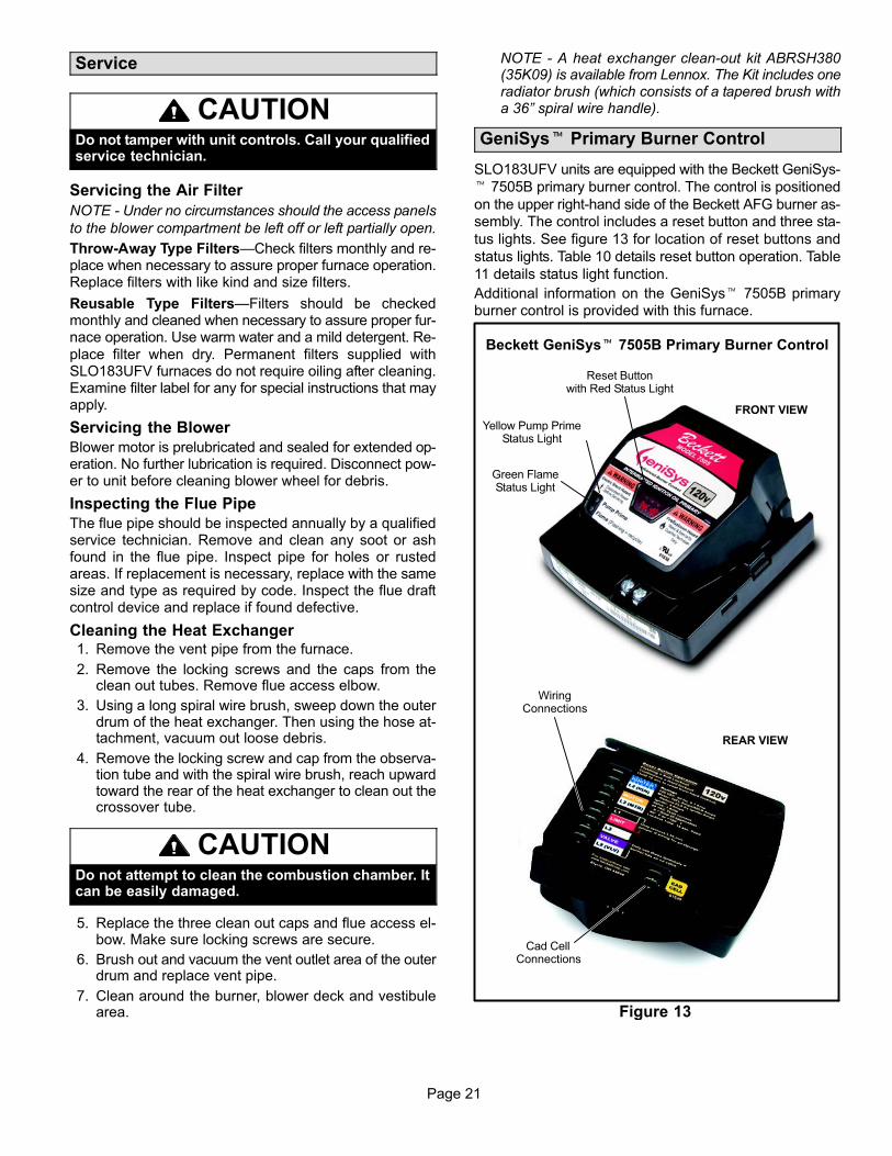
GeniSys� Primary Burner Control
SLO183UFV units are equipped with the Beckett GeniSys-
� 7505B primary burner control. The control is positioned
on the upper right−hand side of the Beckett AFG burner as-
sembly. The control includes a reset button and three sta-
tus lights. See figure 13 for location of reset buttons and
status lights. Table 10 details reset button operation. Table
11 details status light function.
Additional information on the GeniSys� 7505B primary
burner control is provided with this furnace.
Figure 13
Beckett GeniSys� 7505B Primary Burner Control
Reset Buttonwith Red Status Light
Yellow Pump PrimeStatus Light
Green FlameStatus Light
FRONT VIEW
WiringConnections
REAR VIEW
Cad CellConnections

Page 22
If the burner is in thebelow state:
Pushing the reset button will:
Button Click(press < 1 second)
Button Hold(press > 1 second)
Button Hold(press 15+ seconds)
tuokcoLtfoSmorfteseRtuokcoLReset from Restricted (Hard) Lockout
Valve−on Delay, Trial for Ignition, Ignition Carryover
Go to pump prime (see �Priming the Pump" above)
Disable the Burner:Any time the burner is running, press and hold the reset button to disable the burner. The burner will remain off as long as the button is held.
Enables pump priming After the reset button has been held for 15 seconds. The button can then be clicked during the next ignition sequence to enter pump prime mode.
Run (igniter is shut off) No action
No action
Pump Prime No action Exit Pump Prime mode and return to Standby
gnihsalFylsuounitnoCnOroloCthgiL
tuokcoLtfoStuokcoL)draH(detcirtseRdeR
Green Flame Sensed during normal operation (Could be straylight during standby)
Recycle
Yellow Control is in pump prime mode or N/A
Table 10Reset Button Operation
Table 11Status Light Function
Reset button currently held for 15+ seconds.
Heating Sequence − Actions & Responses
1. Action: Thermostat calls for heat (W terminal is en-ergized)
Response:
� ST9103A control (A15) closes oil primary controlTR−TW contacts.
� After 15−second prepurge, power is sent to the oildelay valve, ignition occurs and flame isestablished.
� Igition sequence continues for 10 seconds afterflame is sensed. Oil will continue to flow as long ascad cell senses flame.
� Heat fan on ramp timing begins. When timing iscomplete, the indoor blower is at heat speed andwarm air is delivered to the controlled space.
2. Action: Thermostat ends call for heat (W terminalis de−energized)
Response:
� After the thermostat is satisfied, the thermostatcircuit opens. The oil delay valve and burner arede−energized.
� Burner is de−energized.� Heat fan off ramp timing begins. When timing is
complete, indoor blower is de−energized.� Blower control returns to standby mode (oil prima-
ry control and indoor blower are off).
3. Action: Burner fails to light
Response:
� Oil primary control enters soft lockout after ignitionfailure (15 seconds without flame being sensed).Push reset button on primary control for one sec-ond to reset soft lockout.
� After soft lockout reset, oil primary control allowssecond ignition attempt. Primary control entershard lockout after second ignition failure (15 sec-onds without flame being sensed). Push reset but-ton on primary control for 15 seconds until light oncontrol turns yellow to reset hard lockout.
� Burner motor is de−energized.4. Action: Established flame fails
Response:
� Burner motor is de−energized and oil primary con-trol goes into recycle mode.
� If the fan off delay is longer than the recycle timing,the indoor blower continues to run on heatingspeed through the next trial for ignition.
5. Action: Limit Switch Opens
Response:
� Oil primary control de−energizes burner.� Indoor blower is energized immediately at cool
speed.� A15 control opens oil primary control TR−TW con-
tacts.� Indoor blower runs as long as limit stays open.
6. Action: Limit Switch Closes
Response: If there is a heating demand, A15 control
energizes oil primary control and ignition sequence
begins.
Troubleshooting
Burner failure or improper operation can result from a num-ber of different causes. Often the cause can be pinpointedby observing the different types of failure or by the processof elimination. The following troubleshooting charts listsome failures, causes and a sequence of steps to isolatethe point of failure. Check the simplest and most obvious
items before progressing to other items.

Page 23
Troubleshooting: Blower Control Operating Sequence
Action System Response
Thermostat calls for heat. (W terminal is energized.)
ST9103A closes oil primary control TR−TW contacts.
Ignition system and oil primary control start the furnace. Oil flows as long as cad cellsenses flame.
Call for heat energizes burner motor and blower ramping begins for heating mode. Whenramping is complete, the indoor blower is energized at heat speed and warm air is deliveredto the controlled space.
Thermostat ends call for heat. (W terminal is de−energized.)
Oil primary control is de−energized, terminating the burner cycle.
Heat fan off delay timing begins. When timing is complete, the indoor blower is de−ener-gized.
ST9103A returns to standby mode (oil primary control and circulating fan are off).
Burner fails to light. Oil primary control locks out within lockout timing (timing depends on oil primary control).
Burner motor is de−energized.
If heat fan has started, it continues through the selected delay off period.
Established flame fails. Burner motor is de−energized and oil primary control goes into recycle mode.
If selected heat fan off delay is longer than the recycle delay timing, the heat fan continuesto run through the next trial for ignition.
Thermostat begins call for cool. (G and Y terminals are energized.)
Indoor blower is energized at the cool speed.
Cooling compressor turns on immediately.
Thermostat ends call for cool. (G and Y terminals are de−energized.)
Cooling compressor turns off immediately and indoor blower speed ramps down. Circulat-ing fan shuts off after 60 seconds.
Thermostat begins call for fan. (G terminal is energized.)
Indoor blower is energized immediately at 50% of cool speed.
ST9103A may be factory−configured to operate heat speed in this mode.
Thermostat ends call for fan. (G terminal is de−energized.)
Indoor blower is de−energized.
Limit switch string opens. Oil primary control shuts off the burner.
Indoor blower is energized immediately at heat speed.
ST9103A opens oil primary control TR−TW contacts.
Indoor blower runs as long as limit string stays open.
If there is a call for cooling or fan, the indoor blower switches from heat speed to coolspeed.
Limit switch string closes. ST9103A begins heat fan off delay sequence.
Indoor blower turns off after the selected heat fan off delay timing.
ST9103A closes oil primary control TR−TW contacts.
Oil primary control is energized, initiating burner ignition.
Continuous circulating fan is connected. (Optional connectors are available for separate circulat-ing fan speed tap.)
Indoor blower is energized at 50% of cool speed when there is no call for heat, cool or fan.
If fan operation is required by a call for heat, cool, or fan, the ST9103A switches off thecontinuous fan speed tap before energizing the other fan speed.
IAQ accessory is connected. (Optional connectors are available for 120 Vac acces-sories.)
EAC terminals (for IAQ accessories) are energized when the indoor blower is energized ineither the heat or cool speed. EAC terminals are not energized when the optional continu-ous fan terminal is energized.
Humidity control is connected. (Optional connectors are available for 120 Vac humidifi-er.)
Humidifier connections are energized when the burner motor is energized.

Page 24
Troubleshooting: Burner fails to start.
Source Procedure Causes Correction
Thermostat Check thermostat settings.
Thermostat in OFF or COOL Switch to HEAT.
Thermostat is set too lowTurn thermostat to higher tem-perature.
Safety OverloadsCheck burner motor, primarysafety control, & auxiliary limitswitch.
Burner motor overload tripped Push reset button pump motor.
Primary control tripped on safe-ty
Reset primary control.
Auxiliary limit switch tripped onsafety
Reset auxiliary limit.
PowerCheck furnace disconnectswitch & main disconnect.
Open switch Close switch.
Blown fuse or tripped circuitbreaker
Replace fuse or reset circuitbreaker.
Thermostat
Touch jumper wire across TR−TW terminals on primary control.If burner starts, then fault is inthe thermostat circuit.
Broken or loose thermostatwires
Repair or replace wires.
Loose thermostat screw con-nection
Tighten connection.
Dirty thermostat contacts Clean contacts.
Thermostat not level Level thermostat.
Faulty thermostat Replace thermostat.
Open circuit in wiring betweenST9103A and oil primary con-trol.
Check wiring betweenST9103A and oil primary con-trol.
Cad Cell
Disconnect the flame detectorwires at the primary control. Ifthe burner starts, fault is in thedetector circuit.
Flame detector leads areshorted
Separate leads.
Flame detector exposed to light Seal off false source of light.
short circuit in the flame detec-tor
Replace detector.
Primary Control
Place trouble light between theorange and white leads. No lightindicates that no power is goingto the control.
Primary or auxiliary controlswitch is open
Check adjustment. Set themaximum setting.
Jumper terminals; if burnerstarts, switch is faulty, replacecontrol.
Open circuit between discon-nect switch and limit control
Trace wiring and repair or re-place it.
Low line voltage or power fail-ure
Call the power company.
Place trouble light between theorange and white leads. No lightindicates faulty control.
Failed internal control circuit Replace the control.
Burner
Place the trouble light betweenthe orange and white leads tothe burner motor. No light indi-cates that no power is getting tothe motor.
Blown fuse Replace the fuse.
Place trouble light between theblack and white leads to theblower motor. Light indicatespower to the motor and burnerfault.
Binding burner blower wheel Turn off power and rotate theblower wheel by hand. Ifseized, free the wheel or re-place the fuel pump.
Seized fuel pump
Failed burner motor Replace the motor.

Page 25
Troubleshooting: Burner starts, but no flame is established.
Source Procedure Causes Correction
Oil Supply
Check tank gauge or use dipstick.
No oil in tank Fill tank.
Coat dip stick with litmus pasteand insert into bottom of tank.
Water in oil tankIf water depth exceeds 1 inch,pump or drain water.
Listen for pump whine. Tank shut−off valve closed Open valve.
Oil Filters & Oil Line
Listen for pump whine.
Oil line filter is plugged Replace filter cartridges.
Kinks or restriction in oil line Repair or replace oil line.
Plugged fuel pump strainer Clean strainer or replace pump.
Open bleed valve or gauge port.Start the burner. No oil or milkyoil indicates loss or prime.
Air leak in oil supply lineLocate and correct leak.
Tighten all connections.
Oil PumpInstall pressure gauge on pumpand read pressure. Should notbe less than 140 psi.
Pump is partially or completelyfrozen. No pressure and themotor locks out on overload.
Replace pump.
Coupling disengaged or broken− no pressure
Re−engage or replace coupling.
Fuel pressure too low Adjust to 140 psi.
Nozzle
Observe the oil spray (gun as-sembly must be removed fromunit). Inspect the nozzle forplugged orifice or carbon build−up around orifice.
Nozzle orifice pluggedReplace nozzle with the samesize, spray angle, and spraypattern.
Nozzle strainer plugged
Poor or off center spray
Ignition ElectrodesRemove gun assembly and in-spect electrodes.
Fouled or shorted electrodesClean or replace electrodes.
Dirty electrodes
Eroded electrode tipsClean electrode tips and useT−501 gauge to reset the gap to5/32 inches and correctly posi-tion tips.
Improper electrode gap spacing
Improper position of electrodetips
Bad buss bar connection Retension and realign.
Cracked or chipped insulators Replace electrode.
IgnitionTransformer
Start burner and observe spark.Check line voltage to transform-er primary.
Low line voltageCheck voltage at power source.Correct cause of voltage dropor call the power company.
Burned out transformer wind-ings.
Replace the transformer.
No spark or weak sparkProperly ground the transformercase.
Burner Motor
Motor does not come up tospeed and trips out on overload.Turn off power and rotate blowerwheel by hand to check for bind-ing or excessive drag.
Low line voltageCheck voltage at power source.Correct cause of voltage dropor the call power company.
Pump or blower overloadingmotor
Correct cause of overloading.
Faulty motor Replace motor.

Page 26
Troubleshooting: Burner starts and fires, but lock out on safety.
Source Procedure Causes Correction
Poor Fire
After burnerfires, immedi-ately jumperacross flamedetector termi-nals at the pri-mary control.
If burner con-tinues to run,this may bedue to poorfire. Inspectfire.
Unbalanced fire Replace nozzle
Too much air − −lean short fire Reduce combustion air − checkcombustion.
Too little air − − long dirty fire Increase combustion air − checkcombustion.
Excessive draft Adjust barometric draft controlfor correct draft.
Too little draft or restriction Correct draft or remove restric-tion.
Flame Detector
If fire is good,fault is in theflame detector.Check detec-tor circuit.
Faulty cad cell (open circuit) Replace cad cell.
Loose connections or brokencad cell wires
Secure connections or replacecad cell holder and wire leads.
Cad cell cannot sense flameCheck cad cell for proper align-ment. Check cad cell face andclean, if necessary.
Primary Control
If burner locksout on safety,fault is in theprimary con-trol.
Primary control circuit failed Replace primary control.
Troubleshooting: Burner Starts and Fires, but Loses Flame and Lock Out on Safety
Source Procedure Causes Correction
Poor Fire
After burnerfires, immedi-ately jumperacross flamedetector termi-nals at the pri-mary control.
If burner con-tinues to run(does not lockout of safety),fault may bedue to poorfire. Inspectfire.
Unbalanced fire Replace nozzle
Too much air − − lean short fire Reduce combustion air − checkcombustion.
Too little air − − long dirty fire Increase combustion air − checkcombustion.
Excessive draft Adjust barometric draft controlfor correct draft.
Too little draft or restriction Correct draft or remove restric-tion.
Flame Detector
If fire is good,fault is in theflame detector.Check detec-tor circuit.
Faulty cad cell (open circuit) Replace cad cell.
Loose connections or brokencad cell wires
Secure connections or replacecad cell holder and wire leads.
Cad cell cannot sense flameCheck cad cell for proper align-ment. Check cad cell face andclean, if necessary.
Oil Supply
If burner losesflame (doesnot lock out onsafety), fault isin the fuel sys-tem.
Pump loses prime − air slug Prime pump at bleed port
Pump loses prime − air leak insupply line
Check supply line for loose con-nections and tighten fittings.
Water slug in line Check oil tank for water (over 1inch) pump or drain out water.
Partially plugged nozzle ornozzle strainer
Replace nozzle.
Listen for pump whine
Restriction in oil line Clear restriction.
Plugged fuel pump strainer Clean strainer or replace pump.
Cold oil − outdoor tank Change to number 1 oil.

Page 27
Troubleshooting: Burner starts and fires, but short cycles (too little heat)
Source Procedure Causes Correction
Thermostat Check thermostat.
Heat anticipator set too low Correct heat anticipator setting.
Vibration at thermostat Correct source of vibration.
Thermostat in the path of awarm air draft
Shield thermostat from draft orrelocate.
Limit Control
Connect voltmeter between linevoltage connections to primarycontrol (black & white leads). Ifburner cycles due to power inter-ruption, it is cycling on limit.
Dirty furnace air filters Clean or replace filter.
Temperature rise too high
Check fo proper nozzle size.Replace nozzle, if necessary.Check for restrictions and re-move, if necessary.Check speed tap jumper andmake sure it is still in factoryposition.
Blower motor seized or burnedout
Replace motor.
Blower wheel dirty Clean blower wheel.
Wrong motor rotation Replace motor.
Restrictions in return or supplyair system
Correct cause of restriction.
PowerIf voltage fluctuates, fault is in thepower source. Recheck voltageat the power source.
Loose wiring connection Locate and secure connection.
Low or fluctuating line voltage Call power company.
Troubleshooting: Burner runs continuously (too much heat).
Source Procedure Causes Correction
Thermostat
Disconnectthermostatwires at the pri-mary control.
If burner turnsoff, fault is inthe thermostatcircuit.
Shorted or welded thermostatcontacts
Repair or replace the thermo-stat.
Stuck thermostat bimetalClear obstruction or replacethermostat.
Thermostat not level Level thermostat.
Shorted thermostat wires Repair short or replace wires.
Thermostat out of calibration Replace thermostat.
Thermostat in cold draftCorrect draft or relocate thethermostat.
Primary control
If burner doesnot turn off,fault is in theprimary control.
Failed primary control Replace the primary control.

Page 28
Troubleshooting: Burner runs continuously (too little heat).
Source Procedure Causes Correction
Combustion
Check burnercombustion forCO2, stack tem-perature, andsmoke
Low CO2 lessthan 10%.
Too much combustion air Reduce combustion air.
Air leaks into heat exchangeraround inspection door, etc.
Correct cause of air leak.
Excessive overfire draftAdjust barometric draft controlfor correct draft.
Incorrect nozzle assemblydepth
Set to 1.13.
High smokereading morethan a trace.
Dirty or plugged heat exchangerClean heat exchanger.
Readjust burner.
Insufficient overfire draft Increase draft.
Incorrect nozzle assembly depth
Set to 1.13.
Too little combustion air Increase combustion air.
High stack tem-perature is morethan 550�F Net.
Low volume indoor blower airCheck pump coupling forwear / slippage.
Dirty heat exchanger Clean heat exchanger.
Dirty burner blower wheel Clean burner blower wheel.
Dirty furnace air filters Clean or replace filter.
Restricted or closed registers ordampers
Readjust registers or damp-ers.
Oil PressureInspect fire and check
oil pressure.
Partially plugged or bad nozzle Replace nozzle.
Oil pressure is too low (less than 140 psi.)
Increase oil pressure to 140psi.