Embed Size (px)
Citation preview
Dam Safety Guidelines
Part III: ·An Owner's Guidance Manual
WASHINGTON STATE DEPARTMENT OF
E C 0 L 0 G Y July 1992
92-55C
0 printed on recycled paper
WASHINGTON STATE DEPARTMENT OF
E C 0 L 0 G Y
Dam Safety Guidelines
Part III: An Owner's Guidance Manual
Water Resources Program Dam Safety Section
POBox47600 Olympia, Washington 98504-7600
(360) 407-6208
July 1992 92-SSC
AN OWNER'S GUIDANCE MANUAL
INTRODUCTION
The Dam Safety Guidelines are intended to provide dam owners, operators and design engineers with information on activities, procedures and requirements involved in the planning, design, construction, operation and maintenance of dams in the State of Washington. In particular, they provide guidance in meeting the requirements identified in the Dam Safety Regulations, Chapter 173-175 WAC. For convenience of the various expected users, the guidelines have been organized into four basic units entitled:
Part I - General Information and Owner Responsibilities Part II - Project Planning and Approval of Dam Construction or Modification Part III - An Owner's Guidance Manual Part IV - Dam Design and Construction
Technical Notes have also been prepared to provide technical information on engineering design and analysis of various project elements. For clarity, all important definitions and terms pertinent to State of Washington dam safety activities are summarized in Appendix A of Part IV.
Part III of the guidelines is a reference manual for dam owners to use in developing plans for operation, monitoring, annual inspection and long term maintenance of their facilities. The manual was prepared by the Association of State Dam Safety Officials (ASDSO) and the Federal Emergency Management Agency (FEMA). Particular emphasis is given in Chapters 5, 6 and 7 to the importance of including procedures for inspection, monitoring and maintenance as part of the normal
operation of a project.
This dam owner's guidance manual is the result of the work of many people and organizations. The Federal Emergency Management Agency supplied the impetus and funding for the project. The Colorado Division of Disaster Emergency Services (DODES) (John P. Byrne, Director) undertook the actual development of the manual and contributed several of the chapters. Jeris A. Danielson, Colorado State Engineer and John P. Byrne served as Co-chairmen of the technical advisory committee. Patricia Hagan, DODES Project Officer, led the development and writing team of Jack Truby, DODES and Professors Lynn Johnson P.E. and Charles Bartholomew P.E. (University of Colorado at Denver, Department of Civil Engineering). Hal Simpson, Colorado Deputy State Engineer, also provided direction and assistance. Development of this national manual would not have been possible without drawing from the excellent dam safety manuals now in use by many states. In particular, the following states provided considerable assistance: Arkansas, Colorado, Kentucky, North Carolina, North Dakota, Ohio, Pennsylvania, Virginia and Wyoming; also, STS Consultants. The Colorado, Ohio, and Pennsylvania manuals were particularly helpful and supplied many of the engineering fundementals and graphics.
The authors are indebted to the cochairmen and the members of the technical advisory committee of dam safety officials - group representing a wide ·range of expertise and local insights - who helped define dam owners' needs and thus, the scope of this book. John Akolt - Colorado John Diebel - Colorado James Doody - California Joseph Ellam - Pennsylvania Charles Gardner - North Carolina Dan Robert Lawrence - Arizona William Riebsame - Colorado Special thanks are extended to Bill Riebsame, University of Colorado, Johan Stolpe and David Butler, as well as Steve Slane and Deborah Handerhan, from the Colorado State Design Center, who contributed significantly to the graphic production. The production team could not have accomplished such a large task without the support of Irwin Glassman, DODES Planning Chief, and the entire DODES staff. Special recognition goes to Nora Rimando for her dedication, creativity and insight in typing the manual.
---
12/86
!'<'•,' "if«,:.,,_,,_;;;;e:h,,,:;;//'!ti"'"'>01~ ·~·'0J.k:4.'°""Ai.,\1,.-,,_~~·Ll't:&L?.&r..i:4;,ci"A%cf.;,;_,44_,,,.J?o¥.i'.:X::::z0i.JZ4~'"':t"ttM~iS:&WJ.?::a.0l~£fu?t~;;~~"1'i'.0:"~~.d0'.:~~t:iiif5-fl!l20d~~rmr111r T~' 7 - ~~~
EXECUTIVE SUMMARY
AF'PROACH TO DAM SAFETY
There is an urgent and continuing need for dam safety in the United States because of thousands of dams are now in place across the U.S. and many more are being built each year. These dams are essential elements of the national infrastructure, but the public risk in case of failure is great; large and growing numbers of lives and valuable properties are at stake. Although there are many who are concerned about dam safety, legal and moral responsibility essentially rests with the dam owner. Dam owners serve society by meeting important national needs and of course, may also profit from dam operations. However, these reasons do not justify the utility and effectiveness ofownership ifthe owner cannot provide safety for people and property. The costs of dam safety are small in comparison to those which follow dam failure, particularly in our modem "litigious" society. Liability due to failure could easily offset years of profitability. The dam owner can directly influence the safety of a dam. Owners can and should develop their own safety program which includes such important elements as inspecting, monitoring through instrumentation, maintaining the structure, emergency action planning and operating. Such a program is directly related to the dam structure and its immediate environment and depends on the owner's knowledge of the dam and how it works.
INTRODUCTION TO DAMS Dams may be either man-made or exist because of natural phenomena, such as landslides or glacial deposition. The majority of dams are manmade structures normally constructed of earthfill or concrete. It is important that a dam owner be aware of the different types of dams, essential component parts of a dam, important
physical conditions likely to influence the dam, and how the key components function.
HAZARDS, RISK, FAILURES Present national loss statistics from dam failure fully justify the need for dam owners to better understand the public risks involved with dam ownership, the kinds of hazards that promote these risks and the reasons why dams fail. Public risk is high because people have been allowed to settle below dams in potential inundation zones and because new dams are being built in less than ideal sites. Other elements of risk include natural phenomena such as floods, earthquakes and landslides. These hazards threaten dam structures and their surroundings. Floods that exceed the capacity of a dam's spillway and then erode the dam or abutments are particularly hazardous, as is seismic activity that may cause cracking or seepage. Similarly, debris from landslides may block a dam's spillway and cause an overflow wave that erodes the abutments and ultimately weaken the structure. The International Commission of Large Dams (!COLD) has determined that the three major categories of dam failure are overtopping by flood, foundation defects and piping. For earthen dams, the major reason for failure was piping or seepage. For concrete dams, the major reasons for failure were associated with foundations. Overtopping was a significant cause of dam failure primarily in cases where there was an inadequate spillway.
DEVELOPING A DAM SAFETY PROGRAM Recognition of the causes and possible impacts of dam failure points out the need for a program to enhance dam safety. Such a program must be based on a safety evaluation to deter
mine a dam's structural and operational safety. The evaluation should identify problems and recommend either remedial repairs, operational restrictions and modifications, or further analyses and studies to determine solutions. A safety program comprises several components . that address the spectrum of possible actions to be taken over the short and long term. Development of a safety program involves a phased process beginning with collection and review of existing information, proceeding to detailed inspections and analyses, and culminating with formal documentation. Much of the. preliminary work can be accomplished by the dam owner with the assistance of state and local public agencies. However, depending upon the number and seriousness of problems identified by the initial assessment, professional assistance by qualified engineers and contractors may be required. Information presented in this manual provides direction on how to proceed with establishing an action to increase the safety of a dam. The discussion details technical and procedural components of the safety program, and necessary forms are provided. The program of inspection for both the initial and continuing safety evaluations establishes the condition of the dam and provides the information necessary for determining specific actions to be taken regarding repairs, operations, and monitoring. The program is cyclical recognizing the need for continued vigilance. Emergency action can hopefully be avoided, but a well thought out plan of action in case of imminent or actual failure can greatly reduce damage and possible loss of life.
INSPECTION GUIDELINES An effective inspection program is essential to identify problems and to provide for safe maintenance of a dam. The inspection program should involve three types of inspections: (1) periodic technical inspections, (2) periodic maintenance inspections, and (3) informal observations by project personnel as they operate the dam. Technical inspections involve specialists familiar with the design and construction of dams and include assessments of structure safety. Maintenance inspections are performed more frequently than
technical ·inspections in order to detect, at an early stage, any detrimental developments in the dam; they involve assessment of operational capability as well as structural stability. The third type of inspection is actually a continuing effort by onsite project personnel (dam tenders, powerhouse operators, maintenance personnel) performed in the course of their normal duties.
INSTRUMENTATION AND MONITORING GUIDELINES Instrumentation of a dam furnishes data to determine if the completed structure is functioning as intended and provides a continuing surveillance of the structure to warn of any unsafe developments. Means and methods available to monitor physical phenomena that can lead to a dam failure include a wide spectrum of instruments and procedures ranging from very simple to very complex. Any program of dam safety instrumentation must involve proper design consistent with other project components, must be based on prevailing geotechnical conditions at the dam, and must include consideration of the hydrologic and hydraulic factors present both before and after the project is in operation. Instrumentation designed for monitoring potential deficiencies at existing dams must take into account the threat to life and property that the dam presents. Thus, the extent and nature of the instrumentation depends not only on the complexity of the dam and the size of the reservoir, but also on the potential for loss of life and property downstream. An instrumentation program should involve instruments and evaluation methods that are as simple and straightforward as the project will allow. Moreover, the dam owner should make a definite commitment to a continuing monitoring program; if the program is not continuing, the installation of instruments and procedures will be wasted. Obviously, the involvement of qualified personnel in the design, installation, monitoring, and evaluation of an instrumentation system is of prime importance to the success of the program. Instrumentation and proper monitoring and evaluation are extremely valuable in determining the performance of a dam. Specific information
that instrumentation can provide includes:
• Warning of a problem • Definition of and analyzing a
problem • Proof that behavior is as expected • Remedial action performance
evaluation
MAINTENANCE GUIDELINES A good maintenance program will protect a dam against deterioration and prolong its life. A poorly maintained dam will deteriorate and can fail. Nearly all the components of a dam and the materials used for dam construction are susceptible to damaging deterioration if not properly maintained. A good maintenance program provides not only protection for the owner, but for the general public as well. Furthermore, the cost of a proper maintenance program is small compared to the cost of major repairs or the loss of life and property and resultant litigation against the dam owner. A dam owner should develop a basic maintenance program based primarily on systematic and frequent inspections. Inspections, as noted in Chapter 5, should be done monthly and after major flood or earthquake events. During each inspection, a checklist of items calling for maintenance should be used.
EMERGENCY ACTION PLAN GUIDELINES Although most dam owners have a high level of confidence in the structures they own and are certain their dams will not fail, history has shown that on occasion dams do fail and that often these failures cause loss of life, injuries and extensive property damage. A dam owner should prepare for this possibility by developing an emergency action plan which provides a systematic means to:
e Identify emergency conditions threatening a dam
• Expedite effective response actions to prevent failure
• Reduce loss of life and property damage should failure occur
A dam owner is responsible for preparing a plan covering these measures and listings actions that the owner and operating personnel should take. He should be familar with the local government officials and agencies responsible for warning and evacuating the public.
It is important that dam owners make full use of others who are concerned with darn safety; emergency plans, will be more effective ifthey integrate the actions of others who can expedite response. People and organizations with whom the dam owner should consult in preparing an emergency action plan include numerous local participants, state and federal agencies. An essential part of the emergency action plan is a list of agencies/ persons to be notified in the event of a potential failure. Possible inclusions for this list should be obtained from and coordinated with local law en
. forcement agencies and local disaster emergency services. These are key people or agencies who can activate public warning and evacuation pr<r cedures or who might be able to assist the dam owner in delaying or preventing failure. Certain key elements must be included in every notification plan. Information about potential inundation (flooding) areas and travel times for the breach (flood) wave is essential. Inundation maps are especially useful in local warning and evacuation planning. Detailed information about identification of inundation areas or the development of maps can be found by contacting the State Engineer's Office or local planning offices.
OPERATIONS PLAN GUIDELINES Establishing an operations procedure or plan calls for detailed: • Dam and reservoir physical char
acteristics data • Descriptions of dam components • Operations instructions for oper
able mechanisms • Inspection instructions • Instrumentation and monitoring
guidelines • Maintenance operations guidelines • Emergency operations guidelines • Bibliographical information A schedule should be established to include both day-t<rday tasks and tasks performed less frequently throughout the year. The schedule formalizes inspection and maintenance procedures so that even· an inexperienced person can determine when a task is to be done.
MEASURES TO REDUCE THE CONSEQUENCES OF DAM FAILURE Liabilities which are determined following a dam failure strongly affect both organizations and individuals, governments and darn owners. Establishing liability is the legal means developed by society to recover damages due to a "wrong" (in this case, lack of dam safety) and re~ resents another perspective on the dam safety problem. A thorough understanding of this legal process can help the dam owner decide the steps to be taken to reduce liability. The dam owner can directly and indirectly influence the introduction and use of a variety ofother measures that will serve to reduce the consequences of dam failure. For example, insurance against the costs which will accrue after a failure will save the dam owner money by spreading costs fr_om a single dam owner to others. Some land use measures instituted by governments represent better means of mitigating future disasters. If pe<r ple are restricted from living in inundation zones, then safety is radically improved. Instituting land use measures represents one of the most effective ways to save lives and pro~ erty over the long term, but such steps are not always acceptable to governments. Thus, given that lives and property are at stake, increasing public awareness and governmental planning are vital measures that also must be considered as ways to reduce the consequences of dam failure. Dam owners can obtain insurance directly and should do so. The other measures discussed here -- land use, public awareness and preparedness planning -- are essentially controlled by local governments. Therefore, dam owners would be wise to encourage as strongly as possible awareness and action in the public sector. Finally, they may also wish to hire consultants from the private sector when the information needed for prudent decisions exceeds their own expertise.
CHAPTER 1 AN APPROACH TO DAM SAFETY
1.0 General ............................................ · 1 1.1 Urgency for Dam Safety . . . . . . . . . . . . . . . . . . . . . . . . . . . . . . 1 1.2 Dam Ownership and Safety . . . . . . . . . . . . . . . . . . . . . . . . . . . 1 1.3 The Increasing Complexity of the Dam Safety Problem . . . 1 1.4 An Approach to Dam Safety. . . . . . . . . . . . . . . . . . . . . . . . . . . 2
CHAPTER 2 INTRODUCTION TO DAMS
2.0 General . . . . . . . . . . . . . . . . . . . . . . . . . . . . . . . . . . . . . . . . . . . . 3 2.1 The Watershed System . . . . . . . . . . . . . . . . . . . . . . . . . . . . . . . 3 2.2 Types of Dams . . . . . . . . . . . . . . . . . . . . . . . . . . . . . . . . . . . . . . 3 2.3 Water Retention Ability . . . . . . . . . . . . . . . . . . . . . . . . . . . . . . 6 2.4 Release of Water . . . . . . . . . . . . . . . . . . . . . . . . . . . . . . . . . . . . 6
CHAPTER 3 HAZARDS, RISKS, FAILURES
3.0 General . . . . . . . . . . . . . . . . . . . . . . . . . . . . . . . . . . . . . . . . . . . . 9 3.1 Hazards As Sources of Risk . . . . . . . . . . . . . . . . . . . . . . . . . . 9
3.1.1 Natural Hazards That Threaten Dams . . . . . . . . . . . . . . . . . . 9 3.1.2 Hazards From Human Activity . . . . . . . . . . . . . . . . . . . . . . . . 11
3.2 Site-Specific Structural Risk . . . . . . . . . . . . . . . . . . . . . . . . . . . 12 3.3 Sources of Dam Failure . . . . . . . . . . . . . . . . . . . . . . . . . . . . . . 12
3.3.1 Three Categories of Structural Failure .................. · 12 3.3.2 Failures By Dam Type . . . . . . . . . . . . . . . . . . . . . . . . . . . . . . . 13 3.3.3 Age And Its Relation To Failure . . . . . . . . . . . . . . . . . . . . . . 15
CHAPTER 4 DEVELOPING A SAFETY PROGRAM
4.0 Objectives of a Safety Program . . . . . . . . . . . . . . . . . . . . . . . . 17 4.1 Guidelines for Assessing Existing Conditions . . . . . . . . . . . . 17 4.2 Procedural Guidelines - A Source Book . . . . . . . . . . . . . . . . 18 4.3 Documenting the Safety Program . . . . . . . . . . . . . . . . . . . . . . 18
CHAPTER 5 INSPECTION GUIDELINES
5.0 Introduction . . . . . . . . . . . . . . . . . . . . . . . . . . . . . . . . . . . . . . . . . 21 5.1 Inspection Guidelines . . . . . . . . . . .. . . .. . . . . . . . . . . . . . .. . 21 5.2 Organizing for Inspection . . . . . . . . . . . . . . . . . . . . . . . . . . . . . 22 5.3 Embankment Dams and Structures . . . . . . . . . . . . . . . . . . . . . 23
5.3.1 Upstream Slope . .. . . . . . . . . . . . . . . . . . . . . . . . . . . . . . . . . . . 23 5.3.2 Downstream Slope . . . . . . . . . . . . . . . . . . . . . . . . . . . . . . . . . . . 23 5.3.3 Crest ................................................ 24 5.3.4 Seepage Areas . . . . . . . . . . . . . . . . . . . . . . . . . . . . . . . . . . . . . . 24
5.4 Concrete Dams and Structures . . . . . . . . . . . . . . . . . . . . . . . . 24 5.5 Spillways . . . . . . . . . . . . . . . . . . . . . . . . . . . . . . . . . . . . . . . . . . . 26 5.6 Inlets, Outlets, and Drains.... . . . . . . . . . . . . . . . . . . . . . . . . . 27 5.7 Other Areas . '......... . . . . . . . . . . . . . . . . . . . . . . . . . . . . . . . 29
CHAPTER 6 INSTRUMENTATION AND MONITORING
6.0 6.1 6.2
6.2.1 6.2.2 6.2.3 6.2.4 6.2.5 6.2.6 6.2.7 6.2.8 6.2.9
6.2.10 6.2.11
6.3
7 .0 7.1
7 .1.1 7.1.2 7.1.3
7 .2 7 .2.1 7 .2.2 7 .2.3 7 .2.4 7 .2.5 7 .2.6 7 .2. 7 7 .2.8 7 .2.9
7 .2.10 7 .2.11
GUIDELINES
General . . . . . . . . . . . . . . . . . . . . . . . . . . . . . . . . . . . . . . . . . . . . 51 Reasons for Instrumentation . . . . . . . . . . . . . . . . . . . . . . . . . . . 51 Instrument Types and Usage .......................... 52 Visual Observations . . . . . . . . . . . . . . . . . . . . . . . . . . . . . . . . . . 52 Movement . . . . . . . . . . . . . . . . . . . . . . . . . . . . . . . . . . . . . . . . . . 52 Pore Pressure and Uplift Pressure . . . . . . . . . . . . . . . . . . . . . 54 Water Level and Flow ............................... 55 Seepage Flow . . . . . . . . . . . . . . . . . . . . . . . . . . . . . . . . . . . . . . . 55 · Water Quality . . . . . . . . . . . . . . . . . . . . . . . . . . . . . . . . . . . . . . . 55 Temperature . . . . . . . . . . . . . . . . . . . . . . . . . . . . . . . . . . . . . . . . 56 Crack and Joint Size . . . . . . . . . . . . . . . . . . . . . . . . . . . . . . . . . 56 Seismic Activity . . . . . . . . . . . . . . . . . . . . . . . . . . . . . . . . . . . . . 57 Weather and Precipitation ............................ 57 Stress and Strain . . . . . . . . . . . . . . . . . . . . . . . . . . . . . . . . . . . . 57 Frequency of Monitoring . . . . . . . . . . . . . . . . . . . . . . . . . . . . . 57
CHAPTER 7 MAINTENANCE GUIDELINES
General . . . . . . . . . . . . . . . . . . . . . . . . . . . . . . . . . . . . . . . . . . . . 61 Maintenance Priorities . . . . . . . . . . . . . . . . . . . . . . . . . . . . . . . . 61 Immediate Maintenance . . . . . . . . . . • . . . . . . . . . . . . . . . . . . . 61 Required Maintenance at Earliest Possible Date . . . . . . . . . 61 Continuing Maintenance . . . . . . . . . . . . .. . . . . . . . . . . . . . . . . 61 Specific Maintenance Items . . . . . . . . . . . . . . . . . . . . . . . . . . . 62 Earthwork Maintenance and Repair . . . . . . . . . . . . . . . . . . . . 62 Riprap Maintenance and Repair . . . . . . . . . . . . . . . . . . . . . . . 63 Vegetation Maintenance . . . . . . . . . . . . . . . . . . . . . . . . . . . . . . 64 Livestock Control . . . . . . . . . . . . . . . . . . . . . . . . . . . . . . . . . . . . 64 Rodent Damage Control . . . . . . . . . . . . . . . . . . . . . . . . . . . . . . 64 Traffic Damage Control . . . . . . . . . . . . . . . . . . . . . . . . . . . . . . 65 Mechanical Maintenance . . . . . . . . . . . . .. . . . .. .. . . . . . . . . . 65 Electrical Maintenance .. .. .. . . . . .. . . .. .. .. . . .. .. . .. . . 66 Cleaning . . . . . . . . . . . . . . . . . . . . . . . . . . . . . . . . . . . . . . . . . . . . 66 Concrete Maintenance . . . .. . . . . . . . . . . . . . . .. . . . . . . . . . . . 66 Metal Component Maintenance . . . . . . . . . . . . . . . . . . . . . . . . 66
CHAPTER 8 EMERGENCY ACTION PLAN GUIDELINES
8.0 The Emergency Action Plan . . . . . . . . . . . . . . . . . . . . . . . . . . 69 8.1 Identification of Emergency Conditions and Initiation of
Emergency Response Actions . . . . . . . . . . . . . . . . . . . . . . . . . 70 8.2 Guidelines for Emergency Notification . . . . . . . . . . . . . . . . . 71
CHAPTER 9 OPERATIONS GUIDELINES
9.0 General . . . . . . . . . . . . . . . . . . . . . . . . . . . . . . . . . . . . . . . . . . . . 75 9.1 Operations Plan Guidelines . . . . . . . . . . . . . . . . . . . . . . . . . . . 75
9.1.1 Background Data . . . . . . . . . . . . . . . . . . . . . . . . . . . . . . . . . . . . 75 9.1.2 Operations Instructions and Records . . . . . . . . . . . . . . . . . . . 76
9.2 Schedule of Routine Tasks . . . . . . . . . . . . . . . . . . . . . . . . . . . . 76 9.3 Record Keeping . . . . . . . . . . . . . . . . . . . . . . . . . . . . . . . . . . . . . 76
CHAPTER 10 REDUCING THE CONSEQUENCES OF DAM FAILURE
10.0 Supplements to a Dam Safety Program . . . . . . . . . . . . . . . . . 79 10.1 Liability . . . . . . . . . . . . . . . . . . . . . . . . . . . . . . . . . . . . . . . . . . . . 79 10.2 Measures to Reduce the Consequences of Dam Failure . . . 80
10.2.1 Insurance . . . . . . . . . . . . . . . . . . . . . . . . . . . . . . . . . . . . . . . . . . . 80 10.2.2 Governmental Assistance . . . . . . . . . . . . . . . . . . . . . . . . . . . . . 81 10.2.3 Consultants Role in Dam Safety . . . . . . . . . . . . . . . . . . . . . . . 82
APPENDIXES
A Inspection Forms . . . . . . . . . . . . . . . . . . . . . . . . . . . . . . . . . . . . 83 B Report Fonn ........................................ 95 C Glossary . . . . . . . . . . . . . . . . . . . . . . . . . . . . . . . . . . . . . . . . . . . . 99 D Selected Bibliography ................................ 113
UST OF TABLES
Table 1.1 Loss of Life and Property from Notable U.S. Dam Failures . . . . . . . . . . . . . . . . . . . . . . . . . . . . . . . . . . . . . . . . . . . . 2
3.1 Hazard Potential Classification for Dams . . . . . . . . . . . . . . . 11 3.2 Examples of Earthen Dam Failures . . . . . . . . . . . . . . . . . . . . 15 3.3 Examples of Concrete Dam Failures . . . . . . . . . . . . . . . . . . . 15 5.1 Inspection Guidelines Directory . . . . . . . . . . . . . . . . . . . . . . . 19 5.2 Inspection Equipment and Its Use . . . . . . . . . . . . . . . . . . . . . 22 6.1 Instrumentation and Monitoring Guidelines Directory . . . . . 49 7.1 Maintenance Guidelines Directory . . . . . . . . . . . . . . . . . . . . . 59 8.1 Emergency Action Guidelines Directory ........... , . . . . 67 8.2 Potential Problems and Immediate Response Actions ... 70-71 8.3 Checklist for Dam Emergency Plans . . . . . . . . . . . . . . . . . . . 72 9.1 Operation Plan - Schedule of Routine Tasks . . . . . . . . . . . . 77
10.1 Comparison of Warning Success for Selected Dam Failures and Flash Floods . . . . . . . . . . . . . . . . . . . . . . . . . . . . . . . . . . . . 81
UST OF FIGURES
Figure 2.1 Typical Dam Site . . . . . . . . . . . . . . . . . . . . . . . . . . . . . . . . . . . . 4 2.2 Embankment Dams . . . . . . . . . . . . . . . . . . . . . . . . . . . . . . . . . . 4 2.3 Concrete Gravity Dam . . . . . . . . . . . . . . . . . . . . . . . . . . . . . . . 5 2.4 Concrete Arch Dam . . . . . . . . . . . . . . . . . . . . . . . . . . . . . . . . . 5 2.5 Cutoff Trench and Upstream Blanket . . . . . . . . . . . . . . . . . . . 7 3.1 Estimated Proportion of Land in Floodplain . . . . . . . . . . . . . 10 3.2 Seismic Risk Map of the United States . . . . . . . . . . . . . . . . . 11 3.3 Dam Failures 1900-1975 . . . . . . . . . . . . . . . . . . . . . . . . . . . . . 13 3.4 Failed Dams, in Percent of Dams Built . . . . . . . . . . . . . . . . . 13 3.5 Dam Failures, Age in Years . . . . . . . . . . . . . . . . . . . . . . . . . . 14 4.1 Procedural Guidelines for a Dam Safety Program . . . . . . . . 18
5.3.1 Inspection Guidelines - Embankment Upstream Slope . . . . 31 5.3.2 Downstream Slope ................................... 32 5.3.3 Embankment Crest ................................... 35 5.3.4 Embankment Seepage Areas .......................... 39
5.4 Concrete Upstream Slope . . . . . . . . . . . . . . . . . . . . . . . . . . . . . 42 5.5 Spillways ........................................... 42 5.6 Inlets, Outlets and Drains . . . . . . . . . . . . . . . . . . . . . . . . . . . . . 46
6.1 a Installation of Permanent Points . . . . . . . . . . . . . . . . . . . . . . . 52 6.lb Plan of Alignment System . . . . . . . . . . . . . . . . . . . . . . . . . . . . 52 6.2 Monitoring Cracks on Embankment .................... 53
6.3a Inclinometer . . . . . . . . . . . . . . . . . . . . . . . . . . . . . . . . . . . . . . . . . 53 6.3b Plot of Inclinometer Readings . . . . . . . . . . . . . . . . . . . . . . . . . 53
6.4 Measuring Displacements . . . . . . . . . . . . . . . . . . . . . . . . . . . . . 54 6.5 Porous Stone Piezometer . . . . . . . . . . . . . . . . . . . . . . . . . . . . . 55 6.6 Typical Observation Well Installation . . . . . . . . . . . . . . . . . . 55 6.7 Standard Weirs . . . . . . . . . . . . . . . . . . . . . . . . . . . . . . . . . . . . . . 56 6.8 Parshall Flume . . . . . . . . . . . . . . . . . . . . . . . . . . . . . . . . . . . . . . 56 6.9 Bucket and Stopwatch Method . . . . . . . . . . . . . . . . . . . . . . . . 57
1
1.0 GENERAL This manual is a safety guide for dam owners. There is a critical and continuing need for dam safety because of the thousands of dams now in place and the many new dams built each year. Although these dams are essential elements of the national infra-structure, the risks to the public posed by their possible failure are great; large and growing number of lives and valuable property are at stake. Although there are many who are concerned about dam safety, legal and moral responsibility essentially rests with the dam owner.
1.1 URGENCY FOR SAFETY The critical need for dam safety is clear. World and national statistics on dam failures show an unacceptable record of losses in both lives and property. The International Commission on Large Dams (ICOLD) reports that more than 8000 people have died so far this century because of the failure of major dams. The record for U.S. losses from major dam failures in recent years, shown in Table 1.1 is also not encouraging. Actual national losses are much higher than indicated because the statistics shown cover neither small dam failures nor many combinations of dam failure and natural flooding events. A more specific examination of the national experience shows that over an 18-year period (1965-1983) thirty lesser failures, or serious incidents that almost led to failure, occrrred in Colorado. The Johnstown, Pennsylvania disaster of 1889 is regarded as one of the nation's great catastrophes, and the potential for future similar catastrophes due to dam failure remains strong. Only a cooperative effort in dam safety involving owners and communities can lessen this potential.
1.2 DAM OWNERSHIP AND SAFETY This manual can be applied to dams owned and operated by a wide range of organizations and people, including state and local governments, public and private agencies, and private citizens. Typical reasons for building dams include water storage for human consumption, agricultural production, power generation, flood control, reduction of soil erosion and recreation. Thus, dam owners serve society by meeting important national needs and may also personally profit from dam operations. However, these are not sufficient reasons for building or owning a dam if the owner cannot provide safety for people and property in · potential inundation zones. In both financial and moral terms, successful dam ownership and the maintenance of safety standards go hand in hand. Investment in dam safety should be accepted as an integral part of project costs and not viewed as an expendable item that can be eliminated if a budget becomes tight (Jansen, 1980). The costs of dam safety are small in comparison to those which follow dam failure, particularly in our modem "litigious" society. Liability due to a failure would probably negate years of potential profits. Many different concerns and possible rewards result from dam ownership, but in the end, success will be in large part measured by a continuing record of dam safety.
1.3 THE INCREASING COMPLEXITY OF THE DAM SAFETY PROBLEM As national needs for water intensify and the value of water increases, more dams are being- built. At the same time, many existing dams are reaching or passing their design life spans and, for various reasons, people continue to settle near dams.: Further, as builders are forced to use poorer sites for dams, the job of protecting life and property becomes more difficult. Therefore, as dam
2
contribution to the reduction of the likelihood and consequences of dam failure and thus, to overall community safety. Liability, insurance coverage, and the roles of the Federal and state governments should all be well understood by an owner. Additionally, an owner should have a thorough knowledge of a dam's physical and social environment, including knowledge of natural and technological hazards that threaten the dam, understanding of the developing human settlement patterns around the dam, and understanding of other events that can lead to structural failure. These indirect means of achieving dam safety are covered in more detail in Chapters 2, 3 and 10. Dam owners, can also influence the safety of dams in more direct ways. Owners can and should develop their own safety programs. These programs should include such important elements as inspection, monitoring through instrumentation, maintenance, emergency action planning, and proper. operatign. Such a program is directly related to a specific dam's structure and its immediate environment and depends on the owner's knowledge of the dam and how it works. Chapter 2 stresses the need for owner's knowledge about the dam, while Chapters 4 through 9 cover the development of a dam owner's safety program.
construction continues and the population grows, exposure of the public to dam failure hazards increases and the overall safety problem becomes more difficult. Governments across the nation have shown increasing concern for this problem and have enacted laws, statutes and regulations that place an increased burden of responsibility on the dam owner. In most states, dam owners are held strictly liable for losses or damages resulting from dam failure. Concurrently, liability insurance costs have risen rapidly.
1.4 AN APPROACH TO DAM SAFETY An owner should be aware of and use both direct and indirect means of achieving dam safety. He can, of course, monitor and work on factors directly in his control (example, structural integrity), and these direct efforts are detailed below. However, the owner may also influence governmental policy and work for positive change in statutes and laws that affect dam safety (example, zoning laws). Such indirect influence by an owner could result in a significant
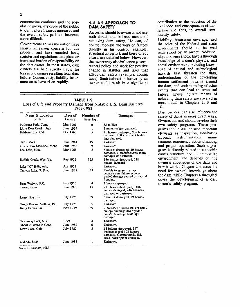
TABLE 1.1 Loss of Life and Property Damage from Notable U.S. Dam Failures,
1963-1983
Name & Location Date of Number of Damages of dam failure lives lost
Mohegan Park, Conn Mar 1963 6 $3 million Little Deer Creek, Utah June 1963 1 Summer cabins damaged. Baldwin Hills, Calif. Dec 1963 5 41 houses destroyed, 986 houses
damaged. 100 apartment buildings damaged.
Swift, Mont. June 1964 19 Unknown Lower Two Medicine, Mont. June 1968 9 Unknown Lee Lake, Mass. Mar 1968 2 6 houses destroyed. 20 houses
damaged, l manufacturing plant damaged or destroyed.
Buffalo Creek, West Va. Feb 1972 125 546 houses destroyed, 538. houses damaged
Lake "O" Hills, Ark. Apr 1972 1 Unknown. Canyon Lake, S. Oak. June 1972 33 Unable to assess damage
because dam failure accompanied damage caused by natural flooding.
Bear Wallow, N.C. Feb 1976 4 l house destroyed. Teton, Idaho June 1976 11 771 houses destroyed, 3,002
houses damaged, 246 business damaged or destroyed.
Laurel Run, Pa. July 1977 39 6 houses destroyed, 19 houses damaged.
Sandy Run and 5 others, Pa July 1977 5 Unknown. Kelly Barnes, Ga. Nov 1979 39 9 houses, 18 house trailers and 2
college buildings destroyed; 6 houses, 5 college buildings damaged.
Swimming Pool, N.Y. 1979 4 Unknown. About 20 dams in Conn. June 1982 0 Unknown. Lawn Lake, Colo. July 1982 3 18 bridges destroyed, 117
businesses and l 08 houses damaged. Campgrounds, fisheries, power plant damaged
DMAD, Utah June 1983 Unknown.
Source: Graham, 1983.
I
3
2.0 GENERAL The purpose of a dam is to impound (store) water for any of several reasons, e.g., flood control, human water supply, irrigation, livestock water supply, energy generation, recreation, or pollution control. This manual primarily concentrates on earthen dams which constitute the majority of structures in place and under development.
2.1 THE WATERSHED SYSTEM Water from rainfall or snowmelt naturally runs down hill into a stream valley and then into larger streams or other bodies of water. The "watershed system" refers to the drainage process through which rainfall or snowmelt is collected into a particular stream valley during natural runoff (directed by gravity). Dams constructed across such a valley then impound the runoff water and release it at a controlled rate. During periods of high runoff, water stored in the reservoir typically increases and overflow through a spillway may occur. During periods of low runoff, reservoir levels usually decrease. The dam owner can normally control the reservoir level to some degree by adjusting the quantity of water released by the dam. Downstream from the dam, the stream continues to exist, but because the quantity of water flowing is normally controlled, very high runoffs (floods) and very low runoffs (drought periods) are avoided.
2.2 TYPES OF DAMS Dams may be either man-made or exist because of natural phenomena, such as landslides or glacial deposition. The majority of dams are manmade structures nonnally constructed of earthfill or concrete. Naturally occurring lakes may also be modified by adding a spillway to provide safe, efficient release of excess water from the resulting reservoir. Dam owners should be aware of the different types of dams, essential components of a dam, how the components function, and important physical conditions likely to affect a dam. This chapter discusses several of these factors. Man-made dams may be classified according to the type of construction materials used, the methods used in construction, the slope or crosssection of the dam, the way the dam resists the forces of the water pressure behind it, the means used for controlling seepage, and occasionally, according the purpose of the dam.
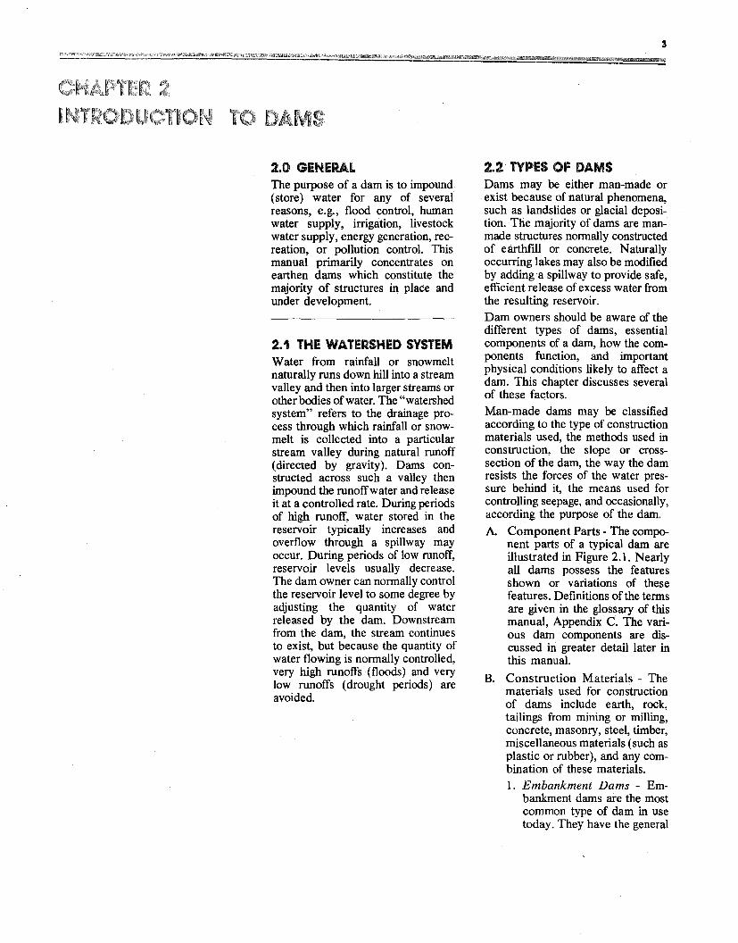
A. Component Parts - The component parts of a typical dam are illustrated in Figure 2.1. Nearly all dams possess the features shown or variations of these features. Definitions of the terms are given in the glossary of this manual, Appendix C. The various darn components are discussed mgreater detail later in this manual.
B. Construction Materials - The materials used for construction of dams include earth, rock, tailings from mining or milling, concrete, masonry, steel, timber, miscellaneous materials (such as plastic or rubber), and any combination of these materials. 1. Embankment Dams - Em
bankment dams are the most common type of dam in use today. They have the general
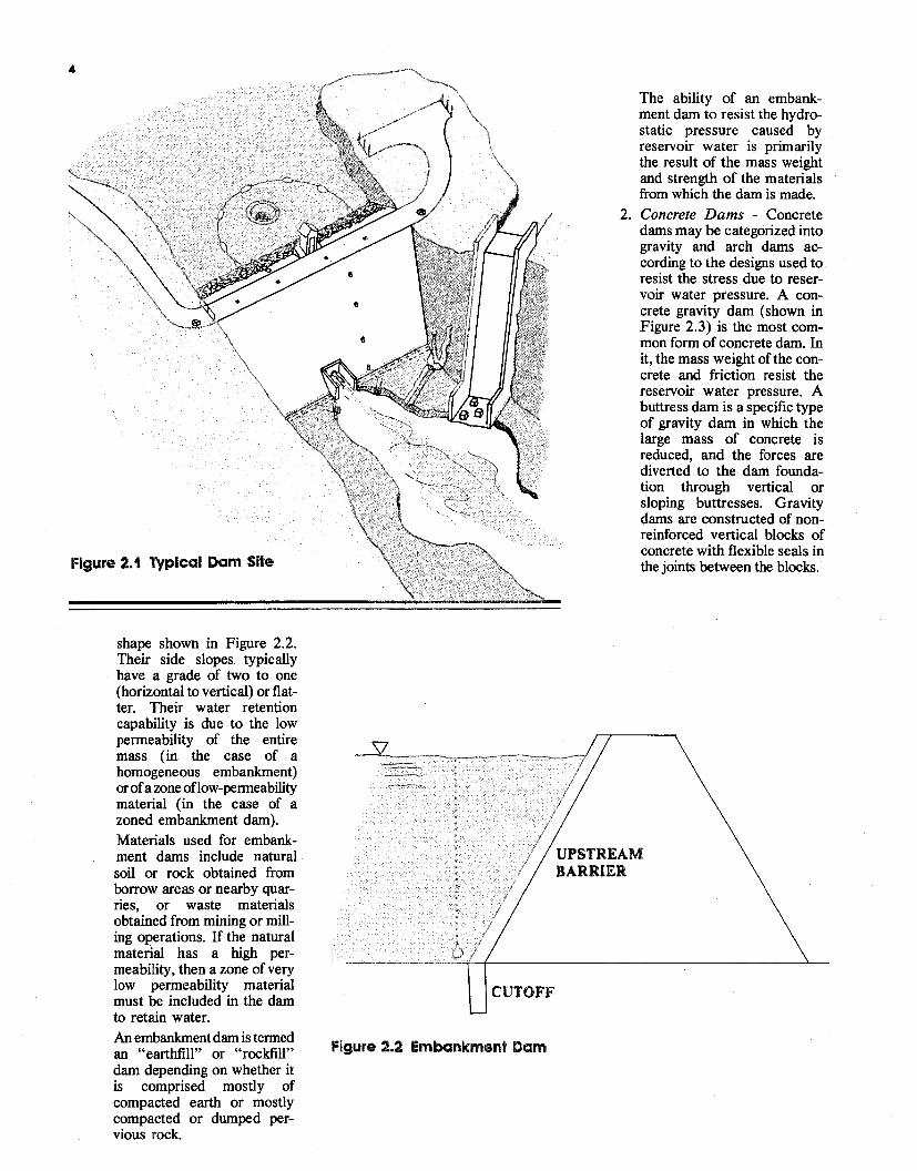
CUTOFF
Figure 2.2 Embankment Dam
4
Figure 2.1 Typical Dam Site
shape shown in Figure 2.2. Their side slopes typically have a grade of two to one (horizontal to vertical) or flatter. Their water retention capability is due to the low permeability of the entire mass (in the case of a homogeneous embankment) orofa zone oflow-permeability material (in the case of a zoned embankment dam). Materials used for embankment dams include natural soil or rock obtained from borrow areas or nearby quarries, or waste materials obtained from mining or milling operations. If the natural material has a high permeability, then a zone of very low permeability material must be included in the dam to retain water. An embankment dam is termed an "earthfill" or "rockfill" dam depending on whether it is comprised mostly of compacted earth or mostly compacted or dumped pervious rock.
The ability of an embankment dam to resist the hydrostatic pressure caused by reservoir water is primarily the result of the mass weight and strength of the materials from which the dam is made.
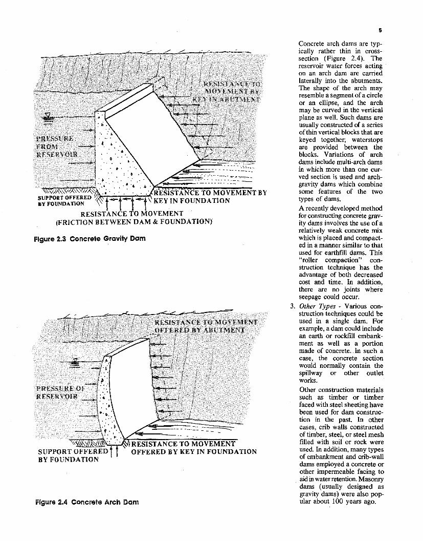
2. Concrete Dams - Concrete dams may be categorized into gravity and arch dams according to the designs used to resist the stress due to reservoir water pressure. A concrete gravity dam (shown in Figure 2.3) is the most common form of concrete dam. In it, the mass weight of the concrete and friction resist the reservoir water pressure. A buttress dam is a specific type of gravity dam in which the large mass of concrete is reduced, and the forces are diverted to the dam foundation through vertical or sloping buttresses. Gravity dams are constructed of nonreinforced vertical blocks of concrete with flexible seals in the joints between the blocks.
5
FROM
. , . . ; .. .
----"'1·~.· .. .......... ~ ., •. .4 ·r:r.~'""".:"!"I!_________
~~~~l"/J7,,~ ·. · .. RESISTANCE TO MOVEMENT BY- - -t \ KEY IN FOUNDATION
RESISTANCE TO MOVEMENT (FRICTION BETWEEN DAM & FOUNDATION)
Figure 2.3 Concrete Gravity Dam
1!&C.'l.1.fil'J.JE:'..,_,~..,I RESISTANCE TO MOVEMENT SUPPORT OFFERED OFFERED BY KEY IN FOUNDATION BY FOUNDATION
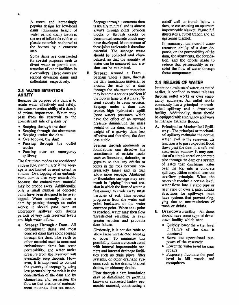
Figure 2.4 Concrete Arch Dam
Concrete arch dams are typically rather thin in crosssection (Figure 2.4). The reservoir water forces acting on an arch dam are carried laterally into the abutments. The shape of the arch may resemble a segment of a circle or an ellipse, and the arch may be curved in the vertical plane as well. Such dams are usually constructed of a series of thin vertical blocks that are keyed together; waterstops are provided between the blocks. Variations of arch dams include multi-arch dams in which more than one curved section is used and archgravity dams which combine some features of the two types of dams. A recently developed method for constructing concrete gravity dams involves the use of a relatively weak concrete mix which is placed and compacted in a manner similar to that used for earthfill dams. This "roller compaction" construction technique has the advantage of both decreased cost and time. In addition, there are no joints where seepage could occur.
3. Other Types - Various construction techniques could be used in a single dam. For example, a dam could include an earth or rockfill embankment as well as a portion made of concrete. In such a case, the concrete section would normally contain the spillway or other outlet works. Other construction materials such as timber or timber faced with steel sheeting have been used for dam construction in the past. In other cases, crib walls constructed of timber, steel, or steel mesh filled with soil or rock were used. In addition, many types of embankment and crib-wall dams employed a concrete or other impermeable facing to aid in water retention. Masonry dams (usually designed as gravity dams) were also popular about 100 years ago.
6
A recent and increasingly popular design for low-head dams (minimum height of water behind dam) involves the use of inflatable rubber or plastic materials anchored at the bottom by a concrete slab. Some dams are constructed for special purposes such to divert water or permit construction of other facilities in river valleys. These dams are termed diversion dams and cofferdams, respectively.
2.3 WATER RETENTION AllUTY Because the purpose of a dam is to retain water effectively and safely, the water retention ability of a dam is of prime importance. Water may pass from the reservoir to the downstream side of a dam by:
• Seeping through the dam • Seeping through the abutments • Seeping under the dam • Overtopping the dam • Passing through the outlet
works • Passing over an emergency
spillway The first three modes are considered undesirable, particularly if the seepage is not limited in areal extent or volume. Overtopping of an embankment dam is also very undesirable because the embankment material may be eroded away. Additionally, only a small number of concrete dams have been designed to be overtopped. Water normally leaves a dam by passing through an outlet works; it should pass over an emergency spillway only during periods of very high reservoir levels and high water inflow.
A. Seepage Through a Dam - All embankment dams and most concrete dams have some seepage through the dam. The earth or other material used to construct embankment dams has some permeability, and water under pressure from the reservoir will eventually seep through. However, it is important to control the quantity of seepage by using low permeability materials in the construction of the dam and by channelling and restricting the flow so that erosion of embankment materials does not occur.
Seepage through a concrete dam is usually minimal and is almost always through joints between blocks or through cracks or deteriorated concrete which may have developed. Maintenance of these joints and cracks is therefore essential. The seepage water should be collected and channelized, so that the quantity of water can be measured and erosion can be minimized.
B. Seepage Around a Dam Seepage under a dam, through the dam foundation material, or around the ends of a dam through the abutment materials may become a serious problem if the flow is large or if it has sufficient velocity to cause erosion. Seepage under a dam also creates high hydrostatic uplift (pore water) pressures which have the effect of an upward pressure diminishing the mass weight of the dam, making the weight of a gravity dam less effective and therefore, the dam less stable. Seepage through abutments or foundations can dissolve the constituents of certain rocks such as limestone, dolomite, or gypsum so that any cracks or joints in the rock become progressively larger and in tum allow more seepage. Abutment or foundation seepage may also result in "piping" internal erosion in which the flow of water is fast enough to erode away small particles of soil. This erosion progresses from the water exit point backward to the water entrance point. When that point is reached, water may then flow unrestricted resulting in even greater erosion and probable dam failure. Obviously, it is not desirable to allow large unrestricted seepage to occur. To minimize this possibility, dams are constructed with internal impermeable barriers and internal drainage facilities such as drain pipes, filter systems, or other drainage systems such as toe drains, blanket drains, or chimney drains. Flow through a dam foundation may be diminished by grouting known or suspected highly permeable material, constructing a
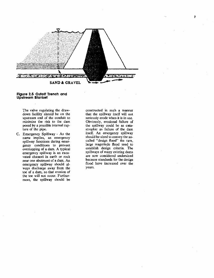
cutoff wall or trench below a dam, or constructing an upstream impermeable blanket. Figure 2.5 illustrates a cutoff trench and an upstream blanket. In summary, the overall water retention ability of a dam depends, on the permeability of the dam, the abutments, the foundation, and the efforts made to reduce that permeability or restrict the flow of water through those components.
2.4 RELEASE OF WATER Intentional release ofwater, as stated earlier, is confined to water releases through outlet works or over emergency spillways. An outlet works commonly has a principal or mechanical spillway and a drawdown facility. Additionally, dams should be equipped with emergency spillways to manage extreme floods.
A. Principal or Mechanical Spillway - The principal or mechanical spillway maintains the normal water level in the reservoir. Its function is to pass expected flood flows past the dam in a safe and nonerosive manner. It may consist of a simple metal or concrete pipe through the dam or a system of gates that discharge water over the top into a concrete spillway. Either method uses the overflow principle. When the reservoir reaches a certain level, water flows into a stand pipe or riser pipe or over a gate. Intake structures for spillways must have systems that prevent clogging due to accumulations of trash or debris.
B. Drawdown Facility- All dams should have some type of drawdown facility which can:
• Quickly lower the water level if failure of the dam is imminent
• Serve the operational purposes of the reservoir
• Lower the water level for dam repairs
• Purposely fluctuate the pool level to kill weeds and mosquitoes
7
SAND&: GRAVEL
Figure 2.5 Cutoff Trench and Upstream Blanket
The valve regulating the drawdown facility should be on the upstream end of the conduit to minimize the risk to the dam posed by a possible internal rupture of the pipe.
C. Emergency Spillway - As the name implies, an emergency spillway functions during emergency conditions to prevent overtopping of a dam. A typical emergency spillway is an excavated channel in earth or rock near one abutment of a dam. An emergency spillway should always discharge away from the toe of a dam, so that erosion of the toe will not occur. Furthermore, the spillway should be
constructed in such a manner that the spillway itself will not seriously erode when it is in use. Obviously, erosional failure of the spillway could be as catastrophic as failure of the dam itself. An emergency spillway should be sized to convey the socalled "design flood" the rare, large magnitude flood used to establish design criteria. The spillways of many existing dams are now considered undersized because standards for the design flood have increased over the years.
3.0 GENERAL Dam failures are severe threats to life and property and are now being recorded and documented much more thoroughly than in the past. Recorded losses have been high. Life and property loss statistics fully justify the need for dam owners to better understand the risks to the public posed by dams, the kinds of hazards that promote these risks, and, generally, the reasons why dams fail. Improving a dam owner's understanding of realistic risks and possible reasons for failure is an essential first step in any overall effort to improve dam safety and preserve the benefits of dam ownership.
3.1 HAZARDS AS SOURCES OF RISK Dam structure itself can be a source of risk due to possible construction flaws and weaknesses which develop because of aging. The site immediately surrounding the structure may also increase structural risk if the dam is not positioned or anchored properly or if excessive reservoir seepage erodes the foundation or abutments. The physical hazards which can cause dam failure are translated into high risks when people or property are threatened, and where the high risks to which Americans are exposed are exacerbated by a number of important factors. For instance, in most states, people are allowed to settle below dams in potential inundation zones, thereby compounding risk. Natural hazards such as floods, earthquakes and landslides are also important contributors to risk. These natural phenomena are considered "hazards" because development has placed people and property in their way, since most natural phenomena existed long before mankind established patterns of settlement. Failure to adjust to these events has been
costly both to dam owners and the public in general. Human behavior is another element of dam failure risk; simple mistakes, operational mismanagement, unnecessary oversights or destructive intent can interact with other hazards to compound the possibility of failure. Thus, a broad range of natural and human hazards exist that, taken separately or in combination, increase the probability of dam failure and injury to people and property. The following discussion of some of the most significant hazards that lead to public risk illustrates the interrelationship of events that can lead to dam failure.
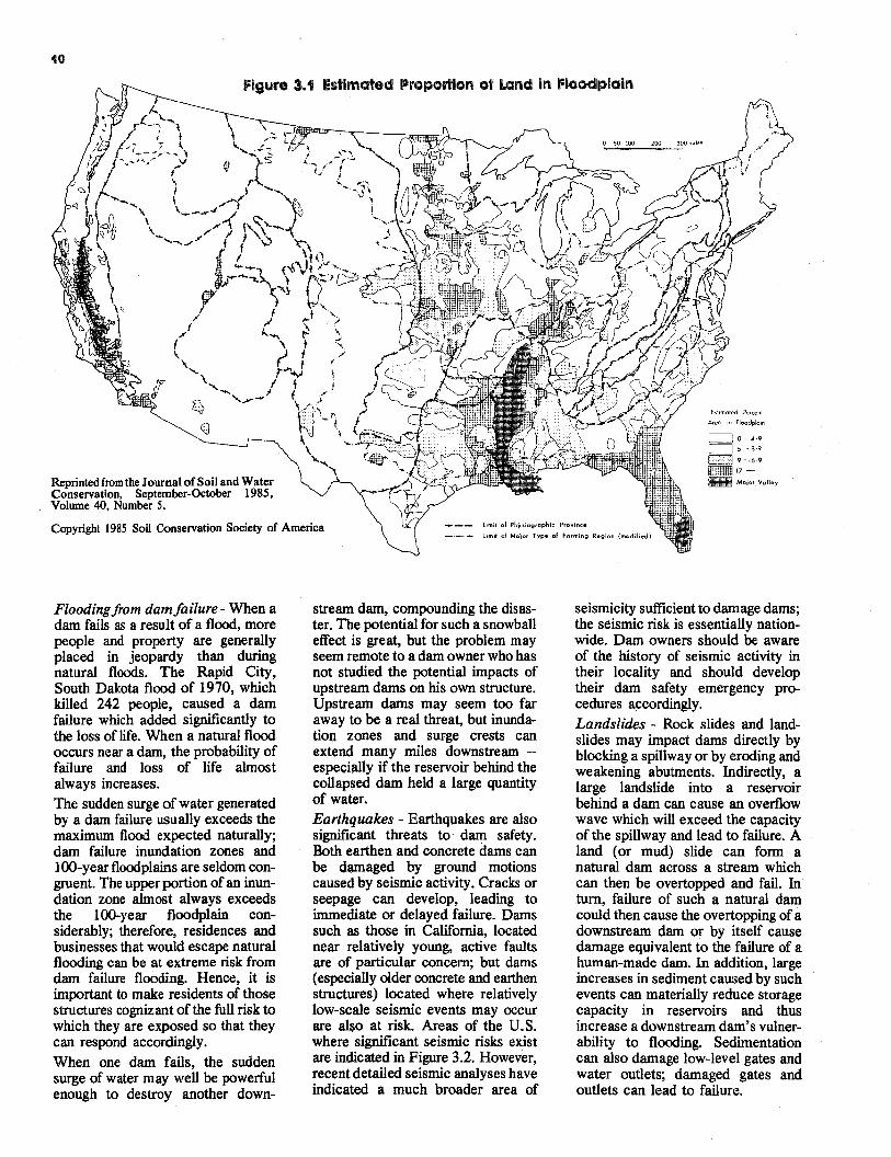
3.1.1 Natural hazards that threaten dams - The most important natural hazards threatening dams include: • Flooding from high precipitation • Flooding from dam failure • Earthquakes • Landslides Flooding from high precipitation Of the natural events that can impact dams, floods are the most significant. A floodplain map of the U.S. (Figure 3.1) gives some idea of the major flood-prone areas. Flash floods can happen anywhere -- even on small drainages -- but especially in the west. Floods are the most frequent and costly natural events that lead to disaster in the U.S. Therefore, flood potentials must be included in risk analyses for dam failure. Dams are sometimes constructed to withstand a probable maximum flood (PMF) assumed to occur on the upstream watershed; this assumed event becomes the basis for the design of safety factors built into the dam (e.g., enhanced structural elements or spillway capacity). However, dams are often built in areas where estimates of the PMF are based on rather short precipitation and runoff records. As a result, spillway capacity may be underestimated.
10
Figure 3.1 Estimated Proportion of Land In Floodplain
0 50 100 200
limit of Physiogrophic
Limit of Major Type of
Es!1mored Percent
Area in Floodploni
C=:J O-H
C=:J 5 - B-9
9-16·9
17
Major Valley
Province
Forming Region {modified)
(J
Reprinted from the Journal of Soil and Water Conservation, September-October 1985, Volume 40, Number 5.
Copyright 1985 Soil Conservation Society of America
Flooding from dam failure - When a dam fails as a result of a flood, more people and property are generally placed in jeopardy than during natural floods. The Rapid City, South Dakota flood of 1970, which killed 242 people, caused a dam failure which added significantly to the loss of life. When a natural flood occurs near a dam, the probability of failure and loss of life almost always increases. The sudden surge of water generated by a dam failure usually exceeds the maximum flood expected naturally; dam failure inundation zones and 100-year floodplains are seldom congruent. The upper portion ofan inundation zone almost always exceeds the 100-year floodplain considerably; therefore, residences and businesses that would escape natural flooding can be at extreme risk from dam failure flooding. Hence, it is important to make residents of those structures cognizant of the full risk to which they are exposed so that they can respond accordingly. When one dam fails, the sudden surge of water may well be powerful enough to destroy another down-
stream dam, compounding the disaster. The potential for such a snowball effect is great, but the problem may seem remote to a dam owner who has not studied the potential impacts of upstream dams on his own structure. Upstream dams may seem too far away to be a real threat, but inundation zones and surge crests can extend many miles downstream -especially if the reservoir behind the collapsed darn held a large quantity of water. Earthquakes - Earthquakes are also significant threats to dam safety. Both earthen and concrete dams can be damaged by ground motions caused by seismic activity. Cracks or seepage can develop, leading to immediate or delayed failure. Darns such as those in California, located near relatively young, active faults are of particular concern; but darns (especially older concrete and earthen structures) located where relatively low-scale seismic events may occur are also at risk. Areas of the U.S. where significant seismic risks exist are indicated in Figure 3.2. However, recent detailed seismic analyses have indicated a much broader area of
seismicity sufficient to damage dams; the seismic risk is essentially nationwide. Darn owners should be aware of the history of seismic activity in their locality and should develop their darn safety emergency procedures accordingly.
Landslides - Rock slides and landslides may impact dams directly by blocking a spillway or by eroding and weakening abutments. Indirectly, a large landslide into a reservoir behind a dam can cause an overflow wave which will exceed the capacity of the spillway and lead to failure. A land (or mud) slide can form a natural darn across a stream which can then be overtopped and fail. In tum, failure of such a natural dam could then cause the overtopping of a downstream dam or by itself cause damage equivalent to the failure of a human-made dam. In addition, large increases in sediment caused by such events can materially reduce storage capacity in reservoirs and thus increase a downstream dam's vulnerability to flooding. Sedimentation can also damage low-level gates and water outlets; damaged gates and outlets can lead to failure.
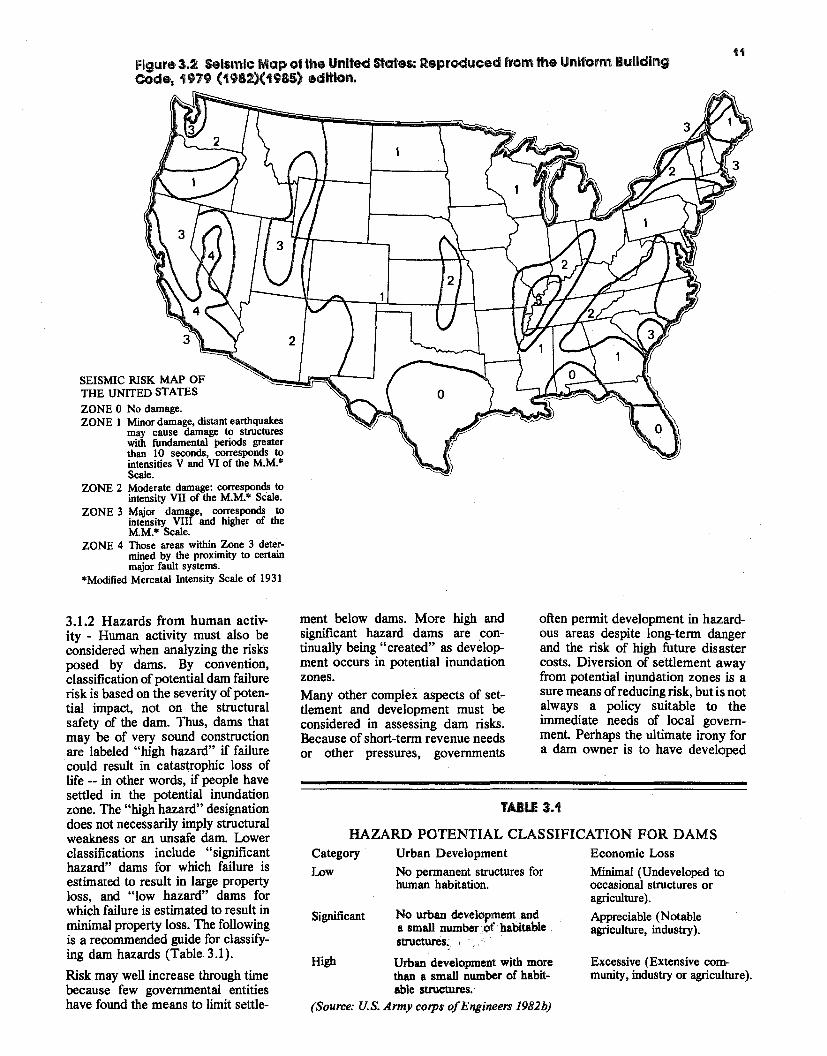
Figure 3.2 Seismic Map of the United states: Reproduced from the Uniform Building Code, 1979 (1982)(1985) edition.
3.1.2 Hazards from human activ· ity - Human activity must also be considered when analyzing the risks posed by dams. By convention, classification of potential dam failure risk is based on the severity of potential impact, not on the structural safety of the dam. Thus, dams that may be of very sound construction are labeled "high hazard" if failure could result in catastrophic loss of life -- in other words, if people have settled in the potential inundation zone. The "high hazard" designation does not necessarily imply structural weakness or an unsafe dam. Lower classifications include "significant hazard" dams for which failure is estimated to result in large property loss, and "low hazard" dams for which failure is estimated to result in minimal property loss. The following is a recommended guide for classifying dam hazards (Table 3.1).
Risk may well increase through time because few governmental entities have found the means to limit settle
ment below dams. More high and significant hazard dams are continually being "created" as development occurs in potential inundation zones. Many other complex aspects of settlement and development must be considered in assessing dam risks. Because of short-term revenue needs or other pressures, governments
often permit development in hazardous areas despite long-term danger and the risk of high future disaster costs. Diversion of settlement away from potential inundation zones is a sure means ofreducing risk, but is not always a policy suitable to the immediate needs of local government Perhaps the ultimate irony for a dam owner is to have developed
TABLE 3.1
HAZARD POTENTIAL CLASSIFICATION FOR DAMS Category Urban Development Economic Loss
Low No permanent structures for Minimal (Undeveloped to human habitation. occasional structures or
agriculture).
Significant No urban development and a small number of. habitable .
Appreciable (Notable agriculture, industry).
structures~.
High Urban development with more Excessive (Extensive comthan a small number of habit munity, industry or agriculture). able structures.
(Source: U.S. Army corps ofEngineers 1982b)
12 \
and implemented a safety program and then to have settlement pennitted in the potential inundation zone so that the owner's liability increases. Two extremes of human purpose the will to destroy through war or terrorism and the urge to develop and to construct - can both result in public risks. Dams have proven to be attractive wartime targets, and they may be tempting to terrorists. On the other hand, a terrorist's advantage from holding the public at risk may well be illusory; the deliberate destruction of a dam is not at all easy to bring about. Yet the possibility exists that such an act could take place, and it should not be discounted by the dam owner. All sorts of other human behavior should be included in risk analyses; vandalism for example cannot be excluded and is in fact, a problem faced by many dam owners. Vegetated surfaces of a dam embankment, mechanical equipment, manhole covers and rock riprap are particularly susceptible to damage by people. Every precaution should be taken to limit access to a dam by unauthorized persons and vehicles. Dirt bikes (motorcycles) and fourwheel drive vehicles, in particular, can severely degrade the vegetation on embankments. Worn areas lead to erosion and more serious problems. Mechanical equipment and associated control mechanisms should be protected from purposeful or inadvertent tampering. Buildings housing mech- · anical equipment should be sturdy, have protected windows, heavy duty doors, and should be secured with deadbolt locks or padlocks. Detachable controls, such as handles and wheels, should be removed when not in use and stored inside the padlocked building. Other controls should be secured with locks and heavy chains where possible. Manhole covers are often removed and sometimes thrown into reservoirs or spillways by vandals. Rock used as riprap around dams is sometimes thrown into the reservoirs, spillways, stilling basins, pipe spillway risers, and elsewhere. Riprap is often displaced by fishennen to form benches. The best way to prevent this abuse is to use rock too large and heavy to move easily or to slush grout the riprap. Otherwise, the rock must be regularly replenished and
other damages repaired Regular visual inspection can easily detect such human impacts. Owners should be aware of their responsibility for the safety of people usirig their facility even though their entry may not be authorized. "No Trespassing" signs should be posted, and fences and warning signs should be erected around dangerous areas. As discussed in Chapter 10, liability insurance can be purchased to protect the owner in the event of accidents.
3.2 SITE-SPECIFIC STRUCTURAL RISK Developing site-specific risk analyses involves consideration ofa number of hazards. Such analyses are helpful in stimulating better awareness, planning and design. In some cases dam structure analyses are quantitatively based, and precise conclusions about engineering and design can be made. Probabilistic analyses can also be important and useful. Still, exact quantitative and probabilistic tools are not yet applicable in many situations and do not fully supplement or replace qualitative analyses - informed perception and judgment of the risks. Judgment and engineering experience should play an important role in reaching useful conclusions in any site-specific analysis of structural risk. As mentioned in Chapter 2, structural risks tend to result from design and construction problems related to the dam materials, construction practice and hydrology. The complexity of the hazard is such that structural design and causes of dam failure are significant areas of research in engineering. Indeed better design criteria have been developed and safer dams are being built, but there is no basis for complacency. Dams continue to age, people continue to move into inundation zones and enough hazards exist that the net risk to the public will remain high for many years.
3.3 SOURCES OF FAILURE There are many complex reasons both structural and non-structural for dam failure. Many sources of failure can be traced to decisions made during the design and construction process and to inadequate maintenance or operational mismanagement. Failures have also resulted from the natural hazards already mentioned large scale flooding and earthquake movement. However, from the perspective ofthe owner, the structure of a dam is the starting point for thorough understanding of the potentials for failure. The International Commission of Large Dams (ICOLD) conducted a study of dam failures and accidents. Figures 3.3 through 3.5 summarize the data (which pertain only to dams more than 15 feet high and include only failures resulting in water releases downstream).
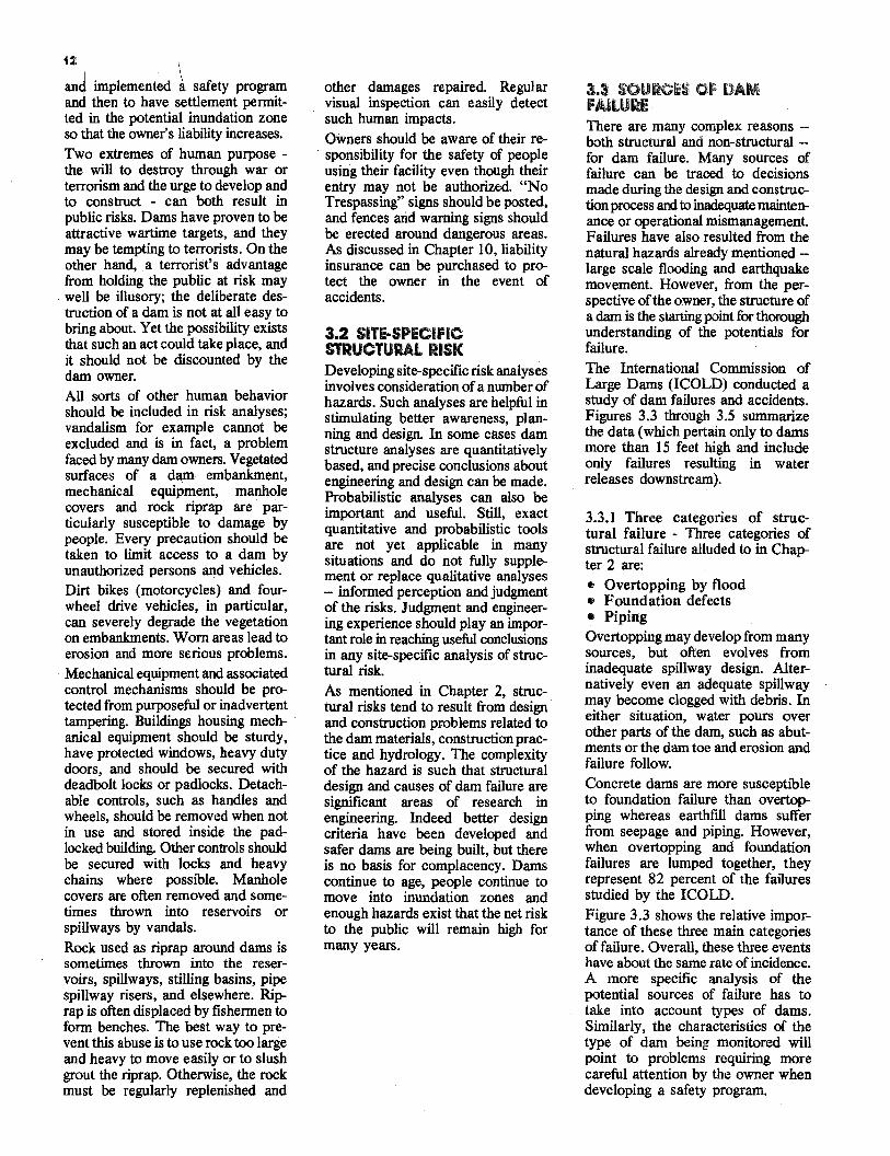
3.3.I Three categories of structural failure - Three categories of structural failure alluded to in Chapter 2 are: • Overtopping by flood • Foundation defects • Piping Overtopping may develop from many sources, but often evolves from inadequate spillway design. Alternatively even an adequate spillway may become clogged with debris. In either situation, water pours over other parts of the dam, such as abutments or the dam toe and erosion and failure follow. Concrete dams are more susceptible to foundation failure than overtopping whereas earthfill dams suffer from seepage and piping. However, when overtopping and foundation failures are lumped together, they represent 82 percent of the failures studied by the ICOLD. Figure 3.3 shows the relative importance of these three main categories offailure. Overall, these three events have about the same rate of incidence. A more specific analysis of the potential sources of failure has to take into account types of dams. Similarly, the characteristics of the type of dam being monitored will point to problems requiring more careful attention by the owner when developing a safety program.
Dam failures 1900-197 5 (over 15 m height)
CONCRETE OVERTOPPING
FOUNDATION
PIPING AND SEEPAGE
OTHERS
0
29
18
FILL OVERTOPPING 35
21
PIPING AND
FOUNDATION
38SEEPAGE
6OTHERS
ALL TYPES 34OVERTOPPING
30 PIPING AND FOUNDATION
28SEEPAGE
OTHERS 8
0 20 40
PERCENT OF FAILURES
( excl. failures during construction and acts of war)
Figure 3.3 Cause of failure. Source: ICOLD (1973).
Dam failures 1900-1975 (over 15 m height)
100 ,,-Foundation
Piping~e Overtopping
CONCRETE FILL
01.-~~--L~~~_._~~~
0 10 20 ~ 0 10 20 AGE IN YEARS AGE JN YEARS
( excl. failures during construction and acts of war)
30
53
Figure 3.4 Age at failure. Source: ICOLD (1973).
13
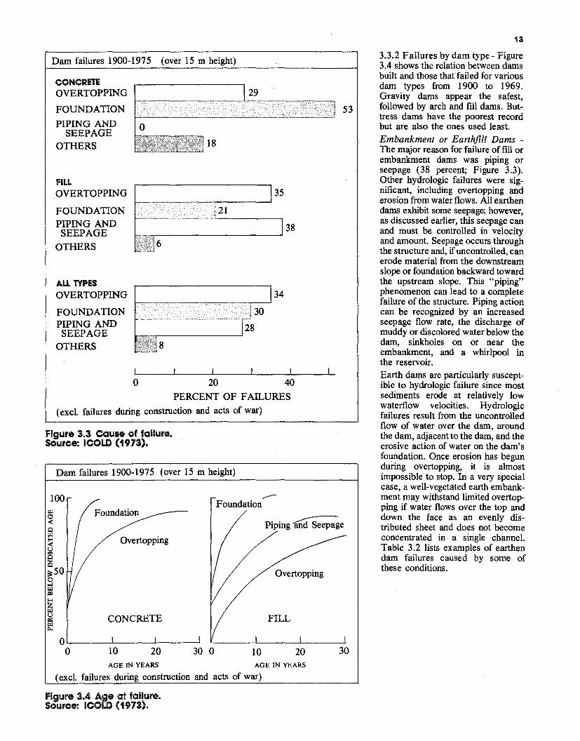
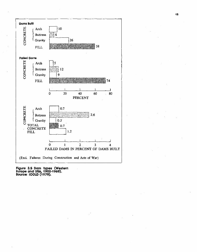
3.3.2 Failures by dam type - Figure 3.4 shows the relation between dams built and those that failed for various dam types from 1900 to 1969. Gravity dams appear the safest, followed by arch and fill dams. Buttress dams have the poorest record but are also the ones used least. Embankment or Earthjill Dams The major reason for failure of fill or embankment dams was piping or seepage (38 percent; Figure 3.3). Other hydrologic failures were significant, including overtopping and erosion from water flows. All earthen dams exhibit some seepage; however, as discussed earlier, this seepage can and must be controlled in velocity and amount. Seepage occurs through the structure and, ifuncontrolled, can erode material from the downstream slope or foundation backward toward the upstream slope. This "piping" phenomenon can lead to a complete failure of the structure. Piping action can be recognized by an increased seepage flow rate, the discharge of muddy or discolored water below the dam, sinkholes on or near the embankment, and a whirlpool in the reservoir. Earth dams are particularly susceptible to hydrologic failure since most sediments erode at relatively low waterflow velocities. Hydrologic failures result from the uncontrolled flow of water over the dam, around the dam, adjacent to the dam, and the erosive action of water on the dam's foundation. Once erosion has begun dunng overtopping, it is almost impossible to stop. In a very special case, a well-vegetated earth embankment may withstand limited overtopping if water flows over the top and down the face as an evenly distributed sheet and does not become concentrated in a single channel. Table 3.2 lists examples of earthen dam failures caused by some of these conditions.
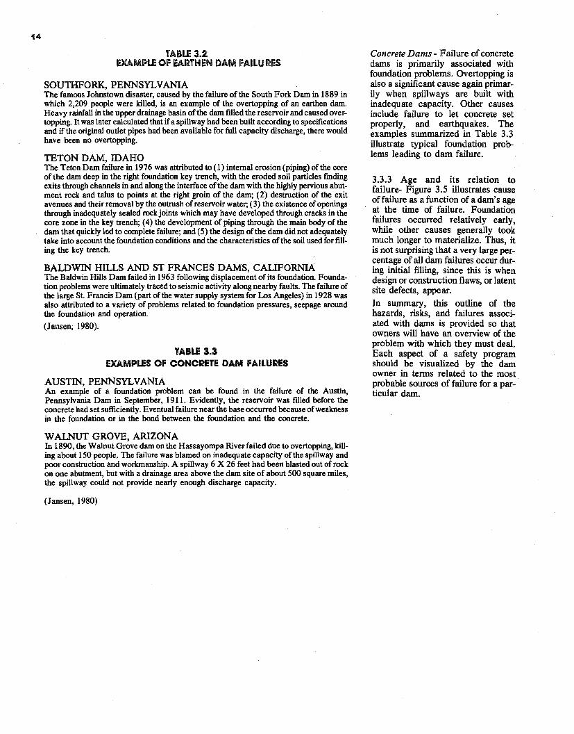
TABLE 3.2 EXAMPLE OF EARTHEN DAM FAILU,RES
SOUTHFORK,PENNSYLVANIA The famous Johnstown disaster, caused by the failure of the South Fork Dam in 1889 in which 2,209 people were killed, is an example of the overtopping of an earthen dam. Heavy rainfall in the upper drainage basin of the dam filled the reservoir and caused overtopping. It was later calculated that ifa spillway had been built according to specifications and if the original outlet pipes had been available for full capacity discharge, there would have been no overtopping.
TETON DAM, IDAHO The Teton Darn failure in 1976 was attributed to (1) internal erosion (piping) of the core of the dam deep in the right foundation key trench, with the eroded soil particles finding exits through channels in and along the interface ofthe darn with the highly pervious abutment rock and talus to points at the right groin of the darn; (2) destruction of the exit avenues and their removal by the outrush of reservoir water; ( 3) the existence ofopenings through inadequately sealed rockjoints which may have developed through cracks in the core zone in the key trench; (4) the development of piping through the main body of the dam that quickly led to complete failure; and ( 5) the design of the darn did not adequately take into account the foundation conditions and the characteristics of the soil used for filling the key trench.
BALDWIN HILLS AND ST FRANCES DAMS, CALIFORNIA The Baldwin Hills Dam failed in 1963 following displacement of its foundation. Foundation problems were ultimately traced to seismic activity along nearby faults. The failure of the large St. Francis Dam (part of the water supply system for Los Angeles) in 1928 was also attributed to a variety of problems related to foundation pressures, seepage around the foundation and operation.
(Jansen, 1980).
TABLE 3.3 EXAMPLES OF CONCRETE DAM FAILURES
AUSTIN, PENNSYLVANIA An example of a foundation problem can be found in the failure of the Austin, Pennsylvania Dam in September, 1911. Evidently, the reservoir was filled before the concrete had set sufficiently. Eventual failure near the base occurred because ofweakness in the foundation or in the bond between the foundation and the concrete.
WALNUT GROVE, ARIZONA In 1890, the Walnut Grove dam on the Hassayompa River failed due to overtopping, killing about 150 people. The failure was blamed on inadequate capacity ofthe spillway and poor construction and workmanship. A spillway 6 X 26 feet had been blasted out of rock on one abutment, but with a drainage area above the dam site of about 500 square miles, the spillway could not provide nearly enough discharge capacity.
(Jansen, 1980)
Concrete Dams - Failure of concrete dams is primarily associated with foundation problems. Overtopping is also a significant cause again primarily when spillways are built with inadequate capacity. Other causes include failure to let concrete set properly, and earthquakes. The examples summarized in Table 3.3 illustrate typical foundation problems leading to dam failure.
3.3.3 Age and its relation to failure- Figure 3.5 illustrates cause offailure as a function of a dam's age at the time of failure. Foundation failures occurred relatively early, while other causes generally took much longer to materialize. Thus, it is not surprising that a very large percentage of all dam failures occur during initial filling, since this is when design or construction flaws, or latent site defects, appear. In summary, this outline of the hazards, risks, and failures associated with dams is provided so that owners will have an overview of the problem with which they must deal. Each aspect of a safety program should be visualized by the dam owner in terms related to the most probable sources of failure for a particular dam.
Dams Built
lArch~
~ Buttressu Gravity~ u FILL 58
Failed Dams
~ Arch
~ u Buttress
~ Gravity u
FILL 74
0 20 40 60 80 PERCENT
~ Arch e Buttress zO G .rav1ty U TOTAL
CONCRETE FILL
2.6
0 1 2 3 4 FAILED DAMS IN PERCENT OF DAMS BUILT
(Exel. Failures During Construction and Acts of War)
Figure 3.5 Dam types (Western Europe and USA., 1900-1969). Source: ICOLD ( 1979).
15
4.0 OBJECTIVES OF A SAFETY PROGRAM The significance of the dam failure problem points out the need for a dam safety program. Such a program should be based on an evaluation to determine a dam's structural and operational safety. The evaluation should identify problems and recommend either remedial repairs, operational restrictions and modifications, or further analyses and studies to determine solutions to the problems. A safety program comprises several components addressing the spectrum of possible actions to be taken over the short and long term. These actions include: • Assessing the condition of the
dam and its components • Conducting preliminary and
detailed inspections • Identifying repairs and continu
ing maintenance needs • Establishing periodic and con
tinuous monitoring capabilities over the long-term
• Establishing an emergency action plan to help minimize adverse impacts should the dam fail
• Establishing operations procedures which recognize dam failure hazards and risks
• Documenting the safety program so that the information established is available at times of need and can be readily updated
Development of a safety program involves a phased process beginning with collection and review of existing information, proceeding to detailed inspections and analyses, and culminating with formal documentation. Much of the preliminary work C8J1 be accomplished by the dam owner with the assistance of state and local public agencies. However, depending upon the number and seriousness of problems identified by the initial assessment, professional assistance by qualified engineers and contl actors may be required.
4.1 GUIDELINES FOR ASSESSING EXISTING CONDITIONS The guidelines for assessing existing conditions are a sequence of steps that will enable a dam owner to secure the information needed to determine the need for subsequent detailed investigations, repairs and maintenance. The steps include: • Reviewing existing data • Visiting the site • Inspecting the dam • Assessing significance of ob
served conditions • Deciding what to do next Reviewing Existing Data - The important first step is to collect and review available information on the dam - its design, construction, and operation. A first requirement is a good map of the site. Maps of the watershed and the downstream channel reaches are also valuable. The design of the dam and its appurtenant structures should be reviewed to assess its actual performance compared to that intended. Engineering records originating during construction should be reviewed to determine if structures were constructed as designed. Records of subsequent construction modifications should be collected, as well as operation records which document the performance of the dam and reservoir. Any previously prepared emergency action plan should be reviewed to determine if it is up to date and workable. All these records should be incorporated into a notebook or file; they are most important in establishing a safety program and its supporting documentation. Chapters 5 through Chapter 10 provide information to aid the development of such documentation. It may be, however, that 1,10 records exist. In this instance, a detailed examination of the structure is appropriate. Visiting the Dam Site - The next step is to visit the site. Undoubtedly, the dam site is well known and has been visited numerous times, but in this visit, there are some particular things to look for. A fresh look at the
_,
INSPECTION
l ./
REPAIRS & MAINTENANCE
' */ / /
OPERATIONS
+ .,
·_, ./
EMERGENCY ACTION 1_,,
/.
I/
./
I/
i
•I /
MONITORING I/
~
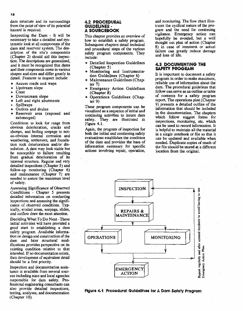
Figure 4.1 Procedural Guidelines for A Dam Safely Program
18
dam structure and its surroundings from the point of view of its potential hazard is required.
Inspecting the Dam - It will be necessary to take a detailed and systematic look at all components of the dam and reservoir system. The description of the site's components (Chapter 2) should aid this inspection. The descriptions are generalized, and it must be recognized that dams and their components come in various shapes and sizes and differ greatly in detail. Features to inspect include:
• Access roads and ways • Upstream slope • Crest • Downstream slope • Left and right abutments • Spillways • Outlets and drains • Reservoir area (exposed and ·
submerged) Conditions to look for range from obvious deterioration, cracks and slumps, and boiling seepage to notso-obvious internal corrosion and weathering, settlement, and foundation rock deterioration and/or dissolution. A dam may look stable but be susceptible to failure resulting from gradual deterioration of its internal structure. Regular and very detailed inspections (Chapter 5) and follow-up monitoring (Chapter 6) and maintenance (Chapter 7) are needed to assure the maximum level of safety.
Assessing Significance of Observed Conditions - Chapter 5 presents detailed information on conducting inspections and assessing the significance of observed conditions. Typically, eroded areas, seepage, s~des, and outflow draw the most attention.
Deciding What To Do Next- These initial activities will have provided a good start to establishing a dam safety program. Available information on design and construction of the dam and later structural modifications provides perspective on its existing condition relative to that intended. Ifno documentation exists, then development of equivalent detail should be a first priority. Inspection and documentation assistance is available from several sources including state and local agencies responsible for dam safety. Professional engineering consultants can also provide detailed inspections, testing, analyses, and documentation (Chapter 10).
4.2 PROCEDURAL GUIDEUNES • A SOURCEBOOK This chapter provides an overview of how to establish a safety program. Subsequent chapters detail technical and procedural steps of the various safety program components. They include: • Detailed Inspection Guidelines
(Chapter 5) • Monitoring and Instrumenta·
tion Guidelines (Chapter 6) • Maintenance Guidelines (Chap
ter 7) • Emergency Action Guidelines
(Chapter 8) • Operations Guidelines (Chap
ter 9) These program components can be visualized as a sequence ofinitial and continuing activities to insure dam safety. They are illustrated in Figure 4.1. Again, the program of inspection for both the initial and continuing safety evaluations establishes the condition of the dam and provides the base of information necessary for specific actions involving repair, operation,
and monitoring. The flow chart illustrates the cyclical nature of the program and the need for c~ntinuing vigilance. Emergency action can hopefully be avoided, but a well thought out plan of action (Chapter 8) in case of imminent or actual failure can greatly reduce damage and loss of life.
4.3 DOCUMENTING THE SAFETY PROGRAM It is important to document a safety program in order to make maximum, reliable use of information about the dam. The procedural guidelines that follow can serve as an outline or table of contents for a safety program report. The operations plan (Chapter 9) presents a detailed outline of the information that should be included in the documentation. The chapters which follow suggest forms for inspections, monitoring, etc. which can be used to record information. It is helpful to maintain all the material in a single notebook or file so that it can be updated and available when needed. Duplicate copies of much of the file should be stored at a different location from the original.
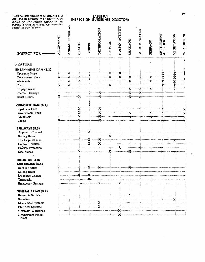
~ !--< :::> u
~ 0!--< !--< z z 0
en
b~ z0 0 >.... .... i:x::
~ CQ < ~ ...l en 0 z 0
~ ~ en ; 0 ~ ~; ....u ~ en ~.... ~ CQ !--< ~ <z ~ ~ ::i ~< u Cl Cl ~ ::c:INSPECT FOR--•
................,--........
~ ~~ .... ~ ~en ';( ~ >< 0 ~~ ~
::c:Cl < !--<
~ fl.. !--< ::s <~ !--<en 0
~ ~ ~~ ~
~en >
FEATURE EMBANKMENT DAM (5.3) Upstream Slope Downstream Slope Abutments Crest Seepage Areas Internal Drainage Relief Drains
CONCRETE DAM (5.4) Upstream Face Downstream Face Abutments Crests
SPILLWAVS (5.5) Approach Channel Stilling Basin Discharge Channel Control Features Erosion Protection Side Slopes
INLETS, OUTLETS AND DRAINS (5.6) Inlet & Outlets Stilling Basin Discharge Channel Trashracks Emergency Systems
GENERAL AREAS (5.7) Reservoir Surface Shoreline Mechanical Systems Electrical Systems Upstream Watershed Downstream Flood-
Plains
X -·-·-* ·····----*··· -· -· x... ---..X--- --X- ---··· ······· ..-.. ~-x -------*· ·····-K·-·-K-------7(--- -x:---······-x-·······-, · -X.·-·········-X-·····-·
····-X-···- ·-·······-k-··
--X-----X-··
X-·····
·······*· ······i-·
··*·
TABLE 5.1INSPECTION GUIDELINES DIRECTORY
Table 5.1 lists features to be inspected at a dam and the problems or deficiencies to be looked for. The specific sections of this manual in which the various features are discussed are also indicated.
19
5.0 INTRODUCTION An effective inspection program is essential for identifying problems and providing safe maintenance of a dam. An inspection program should involve three types of inspections: (1) periodic technical inspections~ (2) periodic maintenance inspections, and ( 3) informal observations by project personnel as they operate the dam. Technical inspections must be performed by specialists familiar with the design and construction of dams and should include assessments of structure safety. Maintenance inspections are performed more frequently than technical inspections in order to detect at an early stage any developments which may be detrimental to the dam. They involve assessing operational capability as well as structural stability. The third type of inspection is actually a continuing effort by on-site project personnel (dam tenders, powerhouse operators, maintenance personnel) performed in the course of their normal duties. Education of new personnel is required to assure the continued effectiveness of these inspections. Visual inspection performed on a regular basis is one of the most economical means a dam owner can use to assure the safety and long life of a dam and its immediate environment. Visual inspection is a straightforward procedure that can be used by any properly trained person to make a reasonably accurate assessment of a dam's condition. The inspection involves careful examination of the surface and all parts of the structure, including its adjacent environment The equipment required is not expensive, and the inspection usually can be completed in less than one day.
5.1 INSPECTION GUIDELINES Table 5.1 lists dam components and conditions which may be observed during an inspection. The table summarizes the detailed guidelines presented in subsequent sections of this chapter. Section 5.3 Embankment dams Section 5. 4 Concrete dams Section 5.5 Spillways Section 5.6 Inlets, outlets and drains Section 5. 7 Other areas At the end of the chapter, diagrams and tabular listings of the .guidelines (Figures 5.3 through 5.6) are presented for the various dam components. The guideline tables provide a quick reference to be used in assessing observed conditions, their probable cause and possible consequences, and remedial actions. The guidelines also point out the HAZARDOUS problems where evaluation by an ENGINEER is required. The dam owner, by applying the maximum prudent effort, can identify any changes in previously noted conditions that may indicate a safety problem. Quick corrective action to conditions requiring attention will promote the safety and extend the useful life of the dam while possibly preventing costly future repairs.
22
5.2 ORGANIZING FOR INSPECTION All inspections should be organized and systematic, and inspectors should use equipment appropriate for the task, record observations accurately, and survey the structure and site comprehensively. Equipment - Equipment useful for inspections is listed in Table 5.2.
Recording Inspection Observations - An accurate and detailed description of conditions observed during each inspection will enable meaningful comparison of conditions observed at different times. All measurements and observed details required to get an accurate picture of a dam's current condition and possible problems should be recorded This information has three elements:
1) Location - The location of any · questionable area or condition
must be accurately described so that the area or condition can be evaluated for changes over time or reexamined by experts. Photographs can be helpful in this regard. The location along the dam, as well as above the toe or below the crest, should be established and recorded. Problems in the outlet or spillway should be similarly located.
2) Extent or Area - The length, width, and depth or height of any suspected problem area should be determined.
3) Descriptive Detail - A brief yet detailed description of an anomalous condition should be given. Some items to include are:
• Quantity of drain outflows • Quantity of seepage from
point and area sources • Color or quantity of sedi
ment in water • Depth of deterioration in
concrete • Length, displacement, and
depth of cracks • Extent of moist, wet, or _
saturated areas • Adequacy of protective
cover • Adequacy of surface drain
age • Steepness or configuration
of slopes • Apparent deterioration rate • Changes in conditions
Coverage - An inspection is conducted by walking along and over a dam as many times as is required to observe the entire structure. From any given location, a person can usually gain a detailed view for 10 to 30 feet in each direction, depending upon the smoothness of the surface or the type of material on the surface, (i.e., grass, concrete, riprap, brush). On the downstream slope a zigzag inspection path should be used to assure that any cracking is detected. Sequence - A sequence of inspection insuring systematic coverage of an entire site is:
• Upstream slope • Crest • Downstream slope • Seepage areas • Outlet • Spillway
TABLE 5.2 Inspection Equipment and Its Use
Inspection Checklist - Serves as a reminder of all important conditions to be examined. Notebook and Pencil - Should be on hand so that observations can be written down at the time they are made, thus reducing mistakes and avoiding the need to return to the site to refresh the inspector's memory. Tape Recorder - Can be effective in making a record of field observations. Camera - Can be used to provide photographs of observed field conditions. Photographs taken from the same vantage points can also be valuable in comparing past and present conditions. Hand Level - May be needed to accurately locate areas of interest and to determine embankment heights and slope. Probe - Provides information on conditions below the surface, such as the depth and softness of a saturated area. Hard Hat - Should be used when inspecting large outlets or working in construction areas. Pocket Tape - Provides accurate dimensional measure~ents so that meaningful comparisons can be made of movements. Flashlight - May be needed to inspect the interior of an outlet in a small dam. Shovel- Useful in clearing drain outfalls, removing debris, and locating monitoring points. Rock Hammer - Can be used to check questionable-looking riprap or concrete for soundness. Care must be taken not to break through thin spots or cause unnecessary damage. Bonker - Is used to determine the condition of support material behind concrete or asphalt faced dams by firmly tapping the surface of the facing material. Concrete fully supported by fill material produces a "click" or "bink" sound, while facing material over a void or hole produces a "clonk" or "honk" sound. A honker can be made of 11/4-inch hard wood dowel with a metal tip firmly fixed to the tapping end. Binoculars - Are useful for inspecting limited access areas, especially on concrete dams. Volume Container and Timer - Are used to make accurate measurements of the rate of leakage. Various container sizes may be required, depending on the flow rates. Stakes and Flagging Tape - Are used to mark areas requiring future attention and to stake the limits of existing conditions, such as cracks and wet areas, for future comparison. Watertight Boots - Are recommended for inspecting areas of the site where standing water is present. Bug Repellent - Is recommended during warm weather. Biting bugs can reduce the efficiency and effectiveness of the inspector. First Aid Kit - Is particularly recommended for inspections in areas where rattlesnakes or othe_r poisonous snakes might be present.
23
Following a consistent sequence lessens the chance of an important condition being overlooked. Reporting inspection results in the same sequence is recommended to ensure consistent records. Inspection forms are included in Appendix A. The forms should be supplemented with additional details specific to a given dam. Record Keeping - A dated report should be filled out for each inspection, and should be filed along with any photographs taken (which should also be dated). In addition to inspection observations, monitoring measurements and weather conditions (especially recent rains, extended dry spells and snow cover) should also be systematically recorded and included in the inspection record. Immediately following an inspection, observations should be compared with previous records to see if there are any trends that may indicate developing problems. If a questionable change or trend is noted, and failure is not imminent, a dam owner should consult a professional engineer experienced in dam safety. Quick reaction to questionable conditions will ensure the safety and long life of a dam and possibly prevent costly repairs. Crucial Inspection Times - There are at least five special times when an inspection is recommended regardless of the regular schedule. 1. Prior to a predicted major rainstorm
or heavy snow melt; check spillway, outlet channel, and riprap,
2. During or after a severe rainstorm; check spillway, outlet channel, and riprap,
3. During or following a severe windstorm; check riprap performance during the storm (if possible) and again after the storm has subsided,
4. Following an earthquake in the area; make a complete inspection immediately after the event and weekly inspections for the next several months to detect any delayed effects,
5. During and immediately after the first reservoir filling; schedule a regular program of frequent complete inspections during the period a reservoir is first being filled to assure that design and site conditions are as predicted. In most states, an inspection and filling
schedule are prescribed by the design engineer and approved by the state engineer.
5.3 EMBANKMENT DAMS AND STRUCTURES Embankment dams constitute the majority of structures in place in the U.S. Table 5.1 presents a general directory of embankment features to be inspected and the conditions to look for. The major features include: e Upstream slope • Downstream slope • Crest • Seepage areas Many ofthe principles and guidelines presented in this section are also applicable to concrete structures.
5.3.1 Upstream Slope - Typically, major problems encountered on an upstream slope are:
• Cracks • Slides • Cave-ins or sink holes • Severe erosion The first three conditions may indicate serious problems within the embankment. Severe erosion obviously can weaken the structure. An upstream slope should receive a close inspection because riprap and high water levels can hide problems. (When walking on riprap, caution should be used to avoid personal injury.) When a reservoir is emptied, the exposed slope should be thoroughly inspected for settlement areas, rodent activity, sink holes, or slides. Also, the reservoir basin (bottom of the reservoir) should be inspected for
• cave-ins or sink holes. Again, most importantly, a crisscross path should be used when inspecting the slope so that cracks and slides can be easily identified. In many instances, sighting along the water line alignment will indicate a change in the uniformity of the slope; an inspector should stand at one end of the dam and sight along the water line checking for straightness and uniformity. If a crack is seen, the crest and downstream slope in its immediate area should be carefully inspected.
Cracks indicate possible foundation movement, embankment failure, or a surface slide. Locating them can be difficult. Cracks can be less than an inch in width, but still several feet deep. Cracks I foot deep usually are
not produced by drying and usually are cause for concern. A line of recently dislodged riprap on an upstream slope could indicate a crack below the riprap. Slides can be almost as difficult to detect as cracks. When a dam is constructed the slopes may not be uniformly graded. Familiarity with the slope configuration at the end ofconstruction can help identify subsequent slope movements. Moreover, the appearance of slides may be subtle; for example, they may produce only about 2 feet of settlement or bulging in a distance of 100 feet or more, yet this would still be a significant amount of settlement. Dated photographs are particularly helpful in detecting such changes. Sink holes or cave-ins result from
, internal erosion of the dam - a very serious condition for earthen embankments. The internal erosion, or piping, may be reflected by turbid seepage water on exit. Surface soil materials may be eroded by wave action, rain runoff, and burrow activities. If allowed to continue, the embankment thickness can be reduced and the structure weakened.
5.3.2 Downstream Slope - A downstream slope should be inspected carefully because it is the area where evidence of developing problems appears most frequently. To assure adequate inspection, this area should be kept free from obscuring weeds, brush, or trees.
When cracks, slides or seepage are noted in the downstream slope, the designated dam safety authorities should be notified immediately. On the downstream slope, some of the more threatening conditions that could be identified are:
• Cracks • Slides • Seepage Cracks can indicate settlement, drying and shrinkage, or the development of a slide. Whatever the cause, cracks should be monitored and changes in length and width noted. Drying cracks may appear and disappear seasonally and normally will not show vertical displacement as will settlement cracks or slide cracks. Slides require immediate detailed evaluation. Early warning signs include a bulge in the embankment near the toe of a dam or vertical dis
placement in the upper portion of an embankment. Seepage is discussed separately below. If any of these three conditions are seen or suspected, the state engineer's office should be notified immediately. If a downstream slope is covered with heavy brush or vegetation, a more concerted search must be made.
5.3.3 Crest - A dam's crest usually provides the primary access for inspection and maintenance. Because surf ace water will pond on a crest unless that surf ace is well maintained, this part of a dam usually requires periodic regrading. However, problems found on the crest should not be simply graded over or covered up. When a questionable condition is found, the state's dam safety engineers should be notified immediately. On the crest, some of the more threatening conditions that may be identified are: • Longitudinal cracking • Transverse cracking • Misalignment Longitudinal cracking can indicate localized instability, differential settlement, and/or movement between adjacent sections of the embankment. Longitudinal cracking is typically characterized by a single crack or a close, parallel system of cracks along the crest in a direction more or less parallel to the axis of the dam. These cracks, which are usually continuous over their length and are usually greater than 1 foot deep, can be differentiated from drying cracks which are usually intermittent, erratic in pattern, shallow, very narrow, and numerous. Longitudinal cracking may precede vertical displacement as a dam attempts to adjust to a position of greater stability. Vertical displacements on the crest are usually accompanied by displacements on the upstream or downstream face ofa dam. Transverse cracking can indicate differential settlement or movement between adjacent segments of a dam. Transverse cracking is usually a single crack or a close, parallel system of cracks which extend across the crest in a direction more or less peipendicular to the length of a dam.
This type of cracking is usually greater than 1 foot in depth. Transverse cracking poses a definite threat to the safety and integrity of a dam. If a crack should progress to a point below the reservoir water surface elevation, seepage could progress along the crack and through the embankment causing severe erosion and ifnot corrected, leading to failure of the dam. Misalignment can indicate relative movement between adjacent portions of a dam - generally in directions petpendicular to the axis of the dam. Excessive settlement of dam material and/or the foundation can also cause misalignment. Most problems are usually detectable during close inspection. Misalignment may, however, only be detectable by viewing a dam from either abutment. Ifon close inspection, the crest appears to be straight for the length ofthe structure, alignment can be further checked by standing away from the dam on either abutment and sighting along the upstream and downstream edges of the crest. On curved dams, alignment can be checked by standing at either end ofa short segment ofthe dam and sighting along the crest's upstream and downstream edges, noting any curvature or misalignment in that section.
5.3.4 Seepage areas - As discussed previously, although all dams have some seepage, seepage in any area on or near a dam can be dangerous, and all seepage should be treated as a potential problem. Wet areas downstream from dams are not usually natural springs, but seepage areas. Seepage must be controlled in both velocity and quantity. High velocity flows through a dam can cause progressive erosion and, ultimately, failure. Saturated areas of an embankment or abutment can move in massive slides and thus also lead to failure. Seepage can emerge anywhere on the downstream face of a dam, beyond the toe, or on the downstream abutments at elevations below normal reservoir levels. A potentially dangerous condition exists when seepage appears on the downstream face above the toe of a dam. Seepage on the downstream slope can cause a slide or failure of the dam by internal erosion (piping). Evidence of seepage may vary from a soft, wet area to a
flowing spring, and may appear initially as only an area where vegetation is lush and dark green in color. Cattails, reeds, mosses, and other marsh vegetation often become established in seepage areas. Downstream abutment areas should always be inspected closely for signs of seepage, as should the area of contact between an embankment and a conduit spillway, drain, or other appurtenant structures and outlets. Slides in the embankment or an abutment may be the result of seepage causing soil saturation and high pore pressures. Since seepage can be present but not readily visible, an intensive search should be made of all downstream areas where seepage water might emerge. Even in short grass cover, seepage may not be visible and must be walked on to be found. Ideally, an inspection for seepage should be made when a reservoir is full.
SA CONCRETE DAMS AND STRUCTURES From a safety standpoint, the principal advantage of concrete dams over earth dams is their relative freedom from failure by erosion during overtopping as well as from embankment slides and piping failures. Although concrete dams comprise a minority of all dams, they are commonly of greater height and storage capacity than earth structures. Thus, they often represent a potentially ~e~ter hazard to life and property. It is nnportant that concrete dam owners be aware of the principal modes of failure of such dams and that they be able to discern between conditions which threaten the safety of the dam and those which merely indicate a need for maintenance. Concrete dams fail for reasons that are significantly different from earth dams. These include: • Structural cracks • Foundation and abutment
weakness e Deterioration due to alkali-
aggregate reaction Should any of these conditions be discovered during inspection, an owner should obtain engineering assistance immediately. Structural cracks occur when portions of the dam are overstressed and are the result of inadequate design, poor construction or faulty materials. Structural cracks are often irregular,
may run at an angle to the major axes of the dam and may exhibit abrupt changes in direction. These cracks can also have noticeable radial, transverse, or vertical displacement Concrete dams transfer a substantial load to the abutments and foundation. Although the concrete of a dam may endure, the natural abutments or foundation may crack, crumble, or move in a massive slide. If this occurs, support for the dam is lost, and it fails. Impending failure of the foundation or abutments may be difficult to detect because initial movements are often very small. Severe deterioration can result from a chemical reaction between alkali present in cements and certain forms of silica present in some aggregates. This chemical reaction produces byproducts of silica gels which cause expansion and loss of strength within concrete. Alkali reaction is characterized by certain observable conditions such as cracking (usually a random pattern on a fairly large scale), and by excessive internal and overall expansion. Additional indications include the presence of a gelatinous exudation or whitish amorphous deposits on the surface, and a chalky appearance of freshly fractured concrete. The alkali-aggregate reaction takes place in the presence of water. Surfaces exposed to the elements or dampened by seepage will deteriorate most rapidly. Once suspected, the condition can be confirmed by a series of tests performed on core samples drilled from a dam. Although the deterioration is gradual, alkaliaggregate reaction cannot be economically corrected by any means now known. Continued deterioration may require total replacement of a structure. Inspection of a concrete dam is similar to that of an earth dam. However, the following additional items should be considered: • Access and safety • Monitoring • Outlet system • Cracks at construction and
expansion joints • Shrinkage cracks • Deterioration due to spalling • Minor leakage Access and safety are important because the faces of concrete dams are often nearly vertical, and sites are
commonly steep-walled rock canyons. Access to the downstream face, toe area, and abutments of such dams may be difficult and require special safety equipment such as safety ropes, or a boatswain's chair. Concrete dams pose a special problem for the dam owner because of the difficulty in gaining close access to the steep surf aces. Regular inspection with a pair of powerful binoculars can initially identify areas where change is occurring. When these changes are noted, a detailed close up inspection should be conducted. Close inspection ofthe upstream face may also require a boatswain's chair or a boat
Monitoring helps detect structural problems in concrete dams such as cracks in the dam, abutments, or foundation. Cracks may develop slowly at first, making it difficult to determine if they are widening or otherwise changing overtime. If a structural crack is discovered, it should be monitored for changes in width, length, and offset, and a monitoring network of instruments should be installed· and read on a regular basis. Outlet system deterioration is a problem for all dams but the frequency of such damage may be higher in concrete dams because of their greater average hydraulic pressure. Thus, outlet system inspection should be emphasized for large concrete dams. Cracks at construction joints exist because concrete dams are built in segments, while expansion joints are built into dams to accommodate volumetric changes which occur in the structures after concrete placement The latter are referred to as "designed" cracks. These joints are typically constructed so that no bond or reinforcing, except non-bonded waterstops and dowels, extend across the joints. Shrinkage cracks often occur when, during original construction, irregularities or pockets in the abutment contact are filled with concrete and not allowed to fully cure prior to placement of adjacent portions of the dam. Subsequent shrinkage of the concrete may lead to irregular cracking at or near the abutment. Shrinkage cracks are also caused by temperature variation. During winter months, the upper portion of a dam may become significantly colder than
those portions which are in direct contact with reservoir water. This temperature differential can result in cracks which extend from the crest for some distance down each face of the dam. These cracks will probably occur at construction or expansion joints, if these are provided. Shrinkage cracks can be a sign that certain portions of the dam are not carrying the design load. In such cases, the total compression load must be carried by a smaller percentage of the structure. It may be necessary to restore load-carrying capability by grouting affected areas. This work requires the assistance of an engineer. Spalling is the process by which concrete chips and breaks away as a result of freezing and thawing. Almost every concrete dam in colder climates experiences continued minor deterioration due to spalling. Because it usually affects only the surface of a structure, it is not ordinarily considered dangerous. However, if allowed to continue, spalling can result in structural damage, particularly ifa dam is of thin cross section. Also, repair is necessary when reinforcing steel becomes exposed The method of repair of spalled areas depends upon the depth of the deterioration. In severe situations, engineering assistance is required. Minor leakage through concrete dams, although unsightly, is not usually dangerous, unless accompanied by structural cracking. The effect may be to promote deterioration due to freezing and thawing. However, increases in seepage could indicate that, through chemical action, materials are being leached from the dam and carried away by the flowing water. Dam owners should note that decreases in seepage could also occur as mineral deposits are formed in portions of the seepage channel. In either case, the condition is not inherently dangerous and detailed study is required before it can be determined if repair is necessary for other than cosmetic reasons.
26
5.5 SPILLWAYS As detailed in Chapter 2, the main function of a spillway is to provide a safe exit for excess water in a reservoir. If a spillway is of inadequate size, a dam could be overtopped and fail. Similarly, defects in a spillway can cause failure by rapid erosion. A spillway should always be kept free of obstructions, have the ability to resist erosion, and be protected from deterioration. Because dams represent a substantial investment and spillways make up a major part of dam costs, a conscientious annual maintenance program should be pursued not only to protect the public but also to minimize costs as well.
The primary problems encountered with spillways include:
• Inadequate capacity e Obstructions • Erosion • Deterioration e Cracks e Undermining of spillway outlet Inadequate capacity is determined by several factors, such as drainage area served, magnitude or intensity of storms in the watershed, storage capacity of the reservoir, and the speed with which rain water flows into and fills the reservoir. An inadequate spillway can cause the water in a reservoir to overtop the dam. Obstructions of a spillway may result from excessive growth of grass and weeds, thick brush, trees, debris, or landslide deposits. An obstructed spillway can have a substantially reduced discharge capacity which can lead to overtopping of the dam. Grass is usually not considered an obstruction; however, tall weeds, brush, and young trees should be periodically cleared from spillways. Similarly, any substantial amount of soil deposited in a spillway whether from sloughing, landslide or sediment transport -- should be immediately removed. Timely removal of large rocks is especially important, since they can obstruct flow and encourage erosion. Erosion of a spillway may occur during a large storm when large amounts of water flow for many hours. Severe damage of a spillway or complete wash-out can result if the spillway cannot resist erosion. If a spillway is excavated out of a rock formation or lined with concrete, erosion is usually not a problem. However, ifa spillway
is excavated in sandy soil, deteriorated granite, clay, or silt deposits, erosion protection is very important. Generally, resistance to erosion can be increased if a spillway channel has a mild slope, or if it is covered with a layer of grass or riprap with bedding material.
A spillway cannot be expected to perform properly if it has deteriorated. Examples include: collapse of side slopes, riprap, concrete lining, approach section, the chute channel, the stilling basin, the discharge channel, or protective grass cover. These problems can cause water to flow under and around the protective material and lead to severe erosion. Remedial action must be taken as soon as any sign of deterioration has been detected. Drying cracks in an earth spillway channel are usually not regarded as a functional problem. However, missing rocks in a riprap lining can be considered a "crack" in the protective cover, and must be repaired at once. Cracks in concrete lining of a spillway are commonly encountered. These cracks may be caused by uneven foundation settlement, shrinkage, slab displacement, or excessive earth or water pressure. Large cracks will allow water to wash out fine material below or behind the concrete slab, causing erosion, more cracks, and even severe displacement ofthe slab. The slab may even be dislodged and washed away by the flow. A severely cracked concrete spillway should be examined by and repaired under the supervision of an engineer.
Undermining of a spillway causes erosion at a spillway outlet, whether it be a pipe or overflow spillway, is one of the most common spillway problems. Severe undermining of the outlet can displace sections of pipe, cause slides in the downstream embankment of the dam and eventually lead to complete failure of a dam. Water must be conveyed safely from the reservoir to a point downstream ofthe dam without endangering the spillway itself or the embankment. Often the spillway outlet is adequately protected for normal flow conditions, but not for extreme flows. It is easy to misestimate the energy and force offlowing water and the resistance of outlet material (earth, rock, concrete, etc). The required level ofprotection is difficult to establish by visual inspection but can usually be determined by hy
draulic calculations performed by a professional engineer. Structures that provide complete erosion control at a spillway outlet are usually expensive, but often necessary. Less expensive protection can also be effective, but require extensive periodic maintenance as areas of erosion and deterioration develop.
The following four factors, often interrelated, contribute to erosion at the spillway outlet:
1. Flows emerge from the outlet are above the stream channel. If outlet flows emerge at the correct elevation, tailwater in the stream channel can absorb a substantial amount of the high velocity, flow and the hydraulic energy will be contained in the stilling basin.
2. Flows emerging from the spillway are generally free of sediment and therefore have substantial sedimentcarrying capacity. In obtaining sediment, moving water will scour soil material from the channel and leave eroded areas. Such erosion is difficult to design for and requires protection of the outlet for a safe distance downstream. from the dam.
3. Flows leaving the outlet at high velocity can create negative pressures that can cause material to be loosened and removed from the floor and walls of the outlet channel. This action is called "cavitation" when it occurs on concrete or metal surfaces. Venting can sometimes be used to relieve
negative pressures.
4. Water leaking through pipe joints and/or flowing along a pipe from the reservoir may weaken the soil structure around the pipe. Inadequate compaction adjacent to such structures during construction can compound this problem.
Procedure for inspection - Spillway inspection is an important part of a dam safety program. The basic objective of spillway inspection is to detect any sign of obstruction, erosion, deterioration, misalignment, or cracking.
When inspecting an earth spillway, one should determine whether side slopes have sloughed, whether there is excessive vegetation in the channel; and one should look for signs of erosion and rodent activity. One should also use a probe to determine the hardness and moisture content of
27
the soil, note the location of particularly wet or soft spots, and see if the stilling basin or drop structure is properly protected with rocks or riprap. Because some erosion is unavoidable during stilling, an owner should also determine whether such erosion might endanger the embankment itself. Ifthe spillway is installed with a sill, a dam owner should also determine if there are any cracks or misalignment in the· sill and check for erosion beneath or downstream of the sill. Commonly encountered defects of concrete spillways and general inspection procedures for cracks, spalling, drains, joints, and misalignment are summarized in the following paragraphs. Hairline cracks are usually harmless. Large cracks should be carefully inspected and their location, width, length, and orientation noted. Deterioration should be determined and exposure· of reinforcing bars should be watched for. Spillway surfaces exposed to freezethaw cycles often suffer from surface spalling. Chemical action, contamination, and unsound aggregates can also cause spalling. If spalling is extensive, the spalled area should be sketched or photographed, showing the length, width, and depth of the area. The problem should be examined closely to see if the remaining concrete has deteriorated or if reinforcing bars are exposed. The concrete should be tapped with a "honker" or rock hammer to determine if voids exist below the surface. Shallow spalling should be examined from time to time to determine if it is becoming worse. Deep spalling should be repaired as soon as possible by an experienced contractor. Walls ofspillways are usually equipped with weep (or drain) holes. Occasionally spillway chute slabs are also equipped with weep holes. If all such holes are dry, the soil behind the wall or below the slab is probably dry. If some holes are draining while others are dry, the dry holes may be plugged by mud or mineral deposits. Plugged weep holes increase the chances for failure of retaining walls or chute slabs. The plugged holes should be probed to determine causes of blockage and soil or deposits cleaned out to restore drainage. Ifthis work is not successful, rehabilitation should be performed as soon as possible under
the supervision of a professional engineer. Spillway retai$g walls and chute slabs are normally constructed in sections. Between adjoining sections, gaps or joints must be tightly sealed with flexible materials such as tar, epoxies, or other chemical compounds. Sometimes rubber or plastic diaphragm materials or copper foil are used to obtain watertightness. During inspection, one should note the location, length, and depth of any missing sealant, and probe open gaps to determine if soil behind the wall or below the slab has been undermined Misalignment of spillway retaining walls or chute slabs may be caused by foundation settlement or earth or water pressure. The inspector should carefully look at the upstream or downstream end of a spillway near the wall to determine if it has been tipped inward or outward. Relative displacement or offset between neighboring sections can be readily identified atjoints. The horizontal as well as vertical displacement should be measured. A fence on top of the retaining wall is usually erected in a straight line at the time of construction; thus any curve or distortion of the fence line may indicate wall deformation.
At the time ofconstruction, the entire spillway chute should form a smooth surface. Thus, measurement of relative movement between neighboring chute slabs at joints will give a good indication of slab displacement. Misalignment or displacement of walls or. the slab is often accompanied by cracks. A clear description of crack patterns should be recorded or photos taken to help in understanding the nature of the displacement.
5.6 INLETS, OUTLETS, AND DRAINS A dam's inlet and outlet works, including internal drains, are essential to the operation of a dam. Items for inspection and special attention include: • Reservoir pool levels • Lake drains and internal drains • Corrosion • Trash racks on pipe spillways • Cavitation The topics discussed above for spillways also are relevant. Reservoir pool levels - Reservoir pool levels are controlled by spillway gates, lake drain and release structures, or flashboards. Flashboards are sometimes used to permanently or temporarily raise the pool level of water supply reservoirs. Flashboards should not be installed or allowed unless there is sufficient freeboard remaining to safely accommodate a design flood. Pool level draw down should not exceed about 1 foot per week for slopes composed of clay or silt materials except in emergency situations. Very flat slopes or slopes with free-draining upstream soils can, however, withstand more rapid draw down rates. Conditions causing or requiring temporary or permanent adjustment of the pool level include:
• Development of a problem which requires that the pool be lowered. Drawdown is a temporary solution until the problem is solved.
• Release of water downstream to supplement stream flow during dry conditions.
• Fluctuations in the service area's demand for water.
• Repair of boat docks in the winter and growth of aquatic vegetation along the shoreline.
·• Requirements for recreation, hydropower, or water fowl and fish management.
Lake drains - A lake drain should always be operable so that the pool level can be drawn down in case ofan emergency or for necessary repair. Lake drain valves or gates that have not been operated for a long time can present a special problem for owners. Ifthe valve cannot be closed after it is opened, the impoundment could be completely drained. An uncontrolled and rapid drawdown could also cause more serious problems such as slides along the saturated upstream slope of the embankment or downstream
21
flooding. Therefore, when a valve or gate is operated, it should be inspected and all appropriate parts lubricated and repaired. It is also prudent to advise downstream residents of large and/or prolonged discharges. To test a valve or gate without risking complete drainage, one must physically block the drain inlet upstream from the valve. Some drains have been designed with this capability and have dual valves or gates, or slots for stoplogs (sometimes called bulkheads) upstream from the valve. Otherwise, divers can be hired to inspect the drain inlet and may be able to construct a temporary block at the inlet. Other problems may be encountered when operating a lake drain. Sediment can build up and block the drain inlet, or debris can enter the valve chamber, hindering its function. The likelihood of these problems is greatly decreased if the valve or gate is operated and maintained periodically. Corrosion - Corrosion is a common problem of pipe spillways and other conduits made of metal. Exposure to moisture, acid conditions, or salt will accelerate corrosion. In particular, acid runoff from strip mine areas will cause rapid corrosion of steel pipes. In such areas, pipes made of noncorrosive materials such as concrete or plastic should be used. Metal pipes which have been coated to resist accelerated corrosion are also available. The coating can be of epoxy, aluminum, zinc (galvanization), asbestos or mortar. Coatings applied to pipes in service are generally not very effective because of the difficulty of establishing a bond. Similarly, bituminous coating cannot be expected to last more than one to two years on flowways. Of course, corrosion of metal parts of operating mechanisms can be effectively treated and prevented by keeping those parts greased and/ or painted. Corrosion can also be controlled or arrested by installing cathodic protection. A metallic anode made out of a material such as magnesium is buried in the soil and is connected to the metal pipe by wire. An electric potential is established which causes the magnesium to corrode and not the pipe.
Trash on pipe spillways - Many dams have pipe and riser spillways. As with concrete spillways, pipe inlets that become plugged with debris or trash reduce spillway capacity. As a result, the potential for overtopping is greatly increased, particularly if there is only one outlet. If a dam has an emergency spillway channel, a plugged principal spillway will cause more frequent and greater than normal flow in the emergency spillway. Because emergency spillways are generally designed for infrequent flows of short duration, serious damage may result. For these reasons trash collectors or racks should be installed at the inlets to pipe spillways and lake drains. A well-designed trashrack will stop large debris that could plug a pipe but allow unrestricted passage of water and smaller debris. Some of the most effective racks have submerged openings which allow water to pass beneath the trash into the riser inlet as the pool level rises. Openings that are too small will stop small debris such as twigs and leaves, which in tum will cause a progression oflarger items to build up, eventually completely blocking the inlet Trashrack openings should be at least 6 inches across regardless of the pipe size. The larger the principal spillway conduit, the larger the trashrack opening should be. The largest possible openings should be used, up to a maximum of about 2 feet. A trashrack should be properly attached to the riser inlet and strong enough to withstand the forces of fast-flowing debris, heavy debris, and ice. If the riser is readily accessible, vandals may throw riprap stone into it. The size of the trashrack openings should not be decreased to prevent this. Instead rock that is larger than the trashrack openings or too large to handle should be used for riprap. Maintenance should include periodic checking of the rack for rusted and broken sections and repair as needed. The trashrack should be checked frequently during and after storms to ensure that it is functioning properly and to remove accumulated debris. Cavitation - When water flows through an outlet system and passes restrictions (e.g., valves), a pressure drop may occur. If localized water pressures drop below the vapor pressure of water, a partial vacuum is
created and the water actually boils, causing shockwaves which can damage the outlet pipes and control valves. This process can be a serious problem for large dams where discharge velocities are high. Testing the outlet system - All valves should be fully opened and closed at least once a year. This not only limits corrosion buildup on control stems and gate guides, but also provides an opportunity to check for smooth operation of the system. Jerky or erratic operation could signal problems, and indicate the need for more detailed inspection. The full range of gate settings should be checked. The person performing the inspection should slowly open the valve, checking for noise and vibration - certain valve settings may result in greater turbulence. He or she should also listen for noise which sounds like gravel being rapidly transported through the system. This sound indicates that cavitation occurring, and these gate settings should be avoided The operation of all mechanical and electrical systems, backup electric motors, power generators, and power and lighting wiring associated with the outlet should also be checked. ·
Inspecting the outlet system Accessible portions of the outlet, such as the outfall structure and control, can be easily and regularly inspected However, severe problems are commonly associated with deterioration or failure of portions of the system which are either buried in the dam or normally under water. Areas to be inspected include: • Outlet pipes 30 inches or greater
in diameter can be inspected internally, provided the system has an upstream valve allowing the pipe to be emptied. Tapping the conduit interior with a hammer can help locate voids behind the pipe. This type of inspection should be performed at least once a year.
• Small diameter outlet pipes can be inspected by remote TV camera if necessary. The camera is channeled through the conduit and transmits a picture back to an equipment truck. This type of inspection is expensive and usually requires the services of an engineer. However, if no other method of inspection is possible, inspection by TV is recommended at least once every five years.
1111
29
Outlet intake structures, wet wells, and outlet pipes with only downstream valves are the most difficult dam appurtenances to inspect because they are usually under water. These should be inspected whenever the reservoir is drawn down or at five year intervals. If a definite problem is suspected, or if the reservoir ~emai~s full over extended periods, divers should be hired to perform an underwater inspection.
5.7 OTHER AREAS Other areas requiring inspection include: 1111 Mechanical and electrical
systems • Reservoir surf ace and shoreline 1111 Upstream watershed • Downstream floodplains Mechanical equipment includes spillway gates, sluice gates or valves for lake drains or water supply pipes, stoplogs, sump pumps, flashboards, relief wells, emergency power sources, siphons, and other devices. All mechanical and associated electrical equipment should be operated at least once a year and preferably more often. The test should cover the full operating range of the equipment under actual operating conditions. Each operating device should be permanently marked for easy identification, and all operating equipment should be kept accessible. All controls .should be checked for proper secunty to prevent vandalism, and finally, all operating instructions should be checked for . clarity and maintained in a secure, but readily accessible location.
The reservoir surf ace and shoreline should be inspected to identify possible problems away from the actual structure. Whirlpools can indicate submerged outlets. Large land slides coming into the reservoir could cause waves overtopping the dam. Floods arise from the upstream watershed. Therefore, characteristics of the watershed, such as impervious areas (e.g. parking lots), relate directly to the magnitude of a flood. Urban development in a watershed can increase the size of flood peaks and the vol~e of runoff, thereby making ~ prev10usly acceptable spillway madequate. Awareness of upstream development and other factors which might influence reservoir inflows is important in order to anticipate possible problems and necessary or modifications in the dam. Development in downstream floodplains is also very important to the darn owner as the extent of development and flood preparedness relate directly to loss of life and damages should the dam fail.
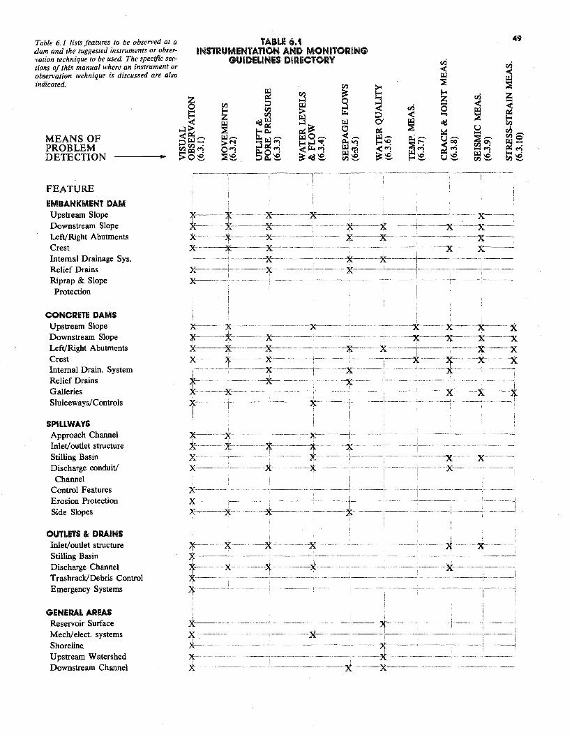
MEANS OF PROBLEM DETECTION
FEATURE
~..:I~<w:::i VJVJ Q:I
>o
-"";
.....
~
~ z ~ w,-..> "'! o~ ~e
VJ
o:d~ ~Q,,
~~--:3 ~ Q.O~:::i Q,, e
TABLE INSTRUMENTATION A
GUIDELINES D
VJ
~ :::i VJ
EMBANKMENT DAM
Table 6.1 lists features to be observed at a dam and the suggested instruments or observation technique to be used. The specific sections of this manual where an instrument or observation technique is discussed are also indicated.
z0-
""'""•·---·-··· ·--~~·"··-· --··-·----···-··---·---~. -··~-~--~--·-···-
Protection
CONCRETE DAMS
Ill
~~ wO-~...:1-:t: <~~ ~ o:d'e
~
w 0 <-Q,, Vl w·w "fl VJ'e
< ~:::i ~ (y ~ o:d VJ
~ u rJ:i ,-..::id w- p.; ,-.. u ,-.. ~ ,-.. VJo ~~ ~r-; ~~ VJ 0) ~"";<~
_..... Ill~ Ill . ~~
~e ~e ue VJ e VJ e
49
v.i
6.1 ND MONITORING IRECTORY v.i
<Ill < ~ VJ ~
VJ ..:I Ill >
~ g
~ ~ v.i 25:3 z v.i - < ~< 0 ....
-
Upstream Slope Downstream Slope Left/Right Abutments Crest Internal Drainage Sys. Relief Drains Riprap & Slope
x--·······
x--· x·········--·-······
Upstream Slope Downstream Slope Left/Right Abutments Crest Internal Drain. System Relief Drains Galleries Sluiceways/ Controls
x---- ·· ·-xx ········~x
x-·
--x x--x--·····x--···x ·········x-·-·--x---x-·---x
·············---··· ···- -·····-·--x-----x
SPILLWAYS Approach Channel Inlet/ outlet structure x·-Stilling Basin x--···· Discharge conduit/ X-·
Channel Control Features X· Erosion Protection Side Slopes
OUTLETS 8i DRAINS
x ·········--x····
x--········ x--·
Inlet/ outlet structure Stilling Basin Discharge Channel Trashrack/Debris Control Emergency Systems
GENERAL AREAS Reservoir Surface Mech/ elect. systems Shoreline Upstream Watershed Downstream Channel
x-·· x x x x
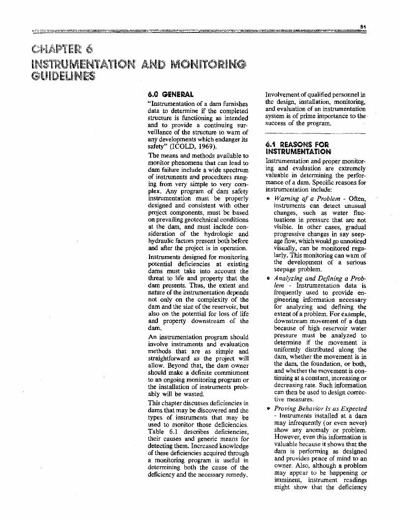
51
6.0 GENERAL "Instrumentation of a dam furnishes data to determine if the completed structure is functioning as intended and to provide a continuing surveillance of the structure to warn of any developments which endanger its safety" (ICOLD, 1969). The means and methods available to monitor phenomena that can lead to dam failure include a wide spectrum of instruments and procedures ranging from very simple to very complex. Any program of dam safety instrumentation must be properly designed and consistent with other project components, must be based on prevailing geotechnical conditions at the dam, and must include consideration of the hydrologic and hydraulic factors present both before and after the project is in operation.
. Instruments designed for monitoring potential deficiencies at existing dams must take into account the threat to life and property that the dam presents. Thus, the extent and nature of the instrumentation depends not only on the complexity of the dam and the size of the reservoir, but also on the potential for loss of life and property downstream of the dam. An instrumentation program should involve instruments and evaluation methods that are as simple and straightforward as the project will allow. Beyond that, the dam owner should make a definite commitment to an ongoing monitoring program or the installation of instruments probably will be wasted This chapter discusses deficiencies in dams that may be discovered and the types of instruments that may be used to monitor those deficiencies. Table 6.1 describes deficiencies, their causes and generic means for detecting them. Increased knowledge of these deficiencies acquired through a monitoring program is useful in determining both the cause of the deficiency and the necessary remedy.
Involvement of qualified personnel in the design, installation, monitoring, and evaluation of an instrumentation system is of prime importance to the success of the program.
6.1 REASONS FOR INSTRUMENTATION Instrumentation and proper monitoring and evaluation are extremely valuable in determining the performance of a dam. Specific reasons for instrumentation include: • Warning of a Problem - Often,
instruments can detect unusual changes, such as water fluctuations in pressure that are not visible. In other cases, gradual progressive changes in say seepage flow, which would go unnoticed visually, can be monitored regularly. This monitoring can warn of the development of a serious seepage problem.
• Analyzing and Defining a Problem - Instrumentation data is frequently used to provide engineering information necessary for analyzing and defining the extent of a problem. For example, downstream movement of a dam because of high reservoir water pressure must be analyzed to determine if the movement is uniformly distributed along the dam, whether the movement is in the dam, the foundation, or both, and whether the movement is continuing at a constant, increasing or decreasing rate. Such information can then be used to design corrective measures.
• Proving Behavior Is as Expected - Instruments installed at a dam may infrequently (or even never) show any anomaly or problem. However, even this information is valuable because it shows that the dam is performing as designed and provides peace of mind to an owner. Also, although a problem may appear to be happening or imminent, instrument readings might show that the deficiency
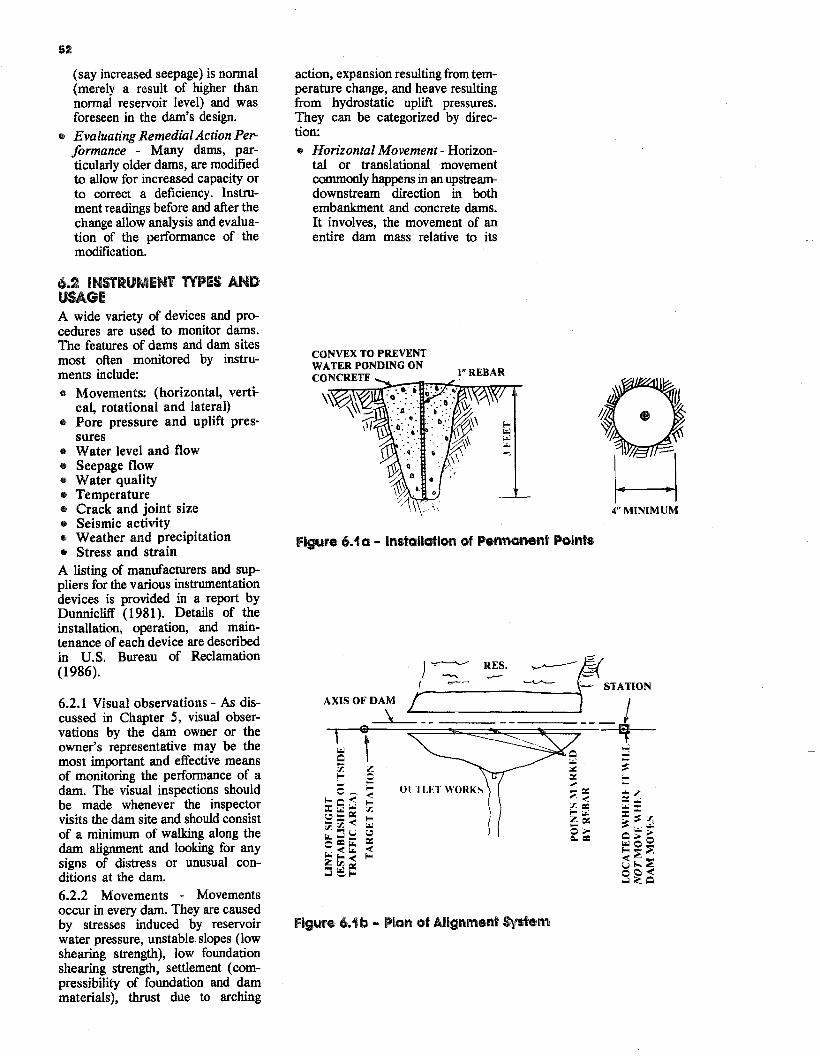
52
(say increased seepage) is normal (merely a result of higher than normal reservoir level) and was foreseen in the dam's design.
• Evaluating Remedial Action Performance - Many dams, particularly older dams, are modified to allow for increased capacity or to correct a deficiency. Instrument readings before and after the change allow analysis and evaluation of the performance of the modification.
6.2 INSTRUMENT TYPES AND USAGE A wide variety of devices and procedures are used to monitor dams. The features of dams and dam sites most often monitored by instruments include: • Movements: (horizontal, verti
cal, rotational and lateral) e Pore pressure and uplift pres
sures • Water level and flow • Seepage flow • Water quality • Temperature • Crack and joint size • Seismic activity • Weather and precipitation • Stress and strain A listing of manufacturers and suppliers for the various instrumentation devices is provided in a report by Dunnicliff (1981). Details of the installation, operation, and maintenance of each device are described in U.S. Bureau of Reclamation (1986).
6.2.1 Visual observations - As discussed in Chapter 5, visual observations by the dam owner or the owner's representative may be the most important and effective means of monitoring the performance of a dam. The visual inspections should be made whenever the inspector visits the dam site and should consist of a minimum of walking along the dam alignment and looking for any signs of distress or unusual conditions at the dam. 6.2.2 Movements - Movements occur in every dam. They are caused by stresses induced by reservoir water pressure, unstable slopes (low shearing strength), low foundation shearing strength, settlement (compressibility of foundation and dam materials), thrust due to arching
action, expansion resulting from temperature change, and heave resulting from hydrostatic uplift pressures. They can be categorized by direction:
• Horizontal Movement- Horizontal or translational movement commonly happens in an upstream-downstream· direction in both embankment and concrete dams. It involves, the movement of an entire dam mass relative to its
CONVEX TO PREVENT WATER PONDING ON
I" REBAR CONCRETE
Figure 6.1 a - Installation of Permanent Points
4"MINIMUM
)~ ~· ._----f~ I "--'-"'- ~ STATION
AXIS OF DAM r--------~~ ___.\~------!---~1
:::
Ol TI.ET WORKS
of Alignment System igure 6.1 b - PlanF
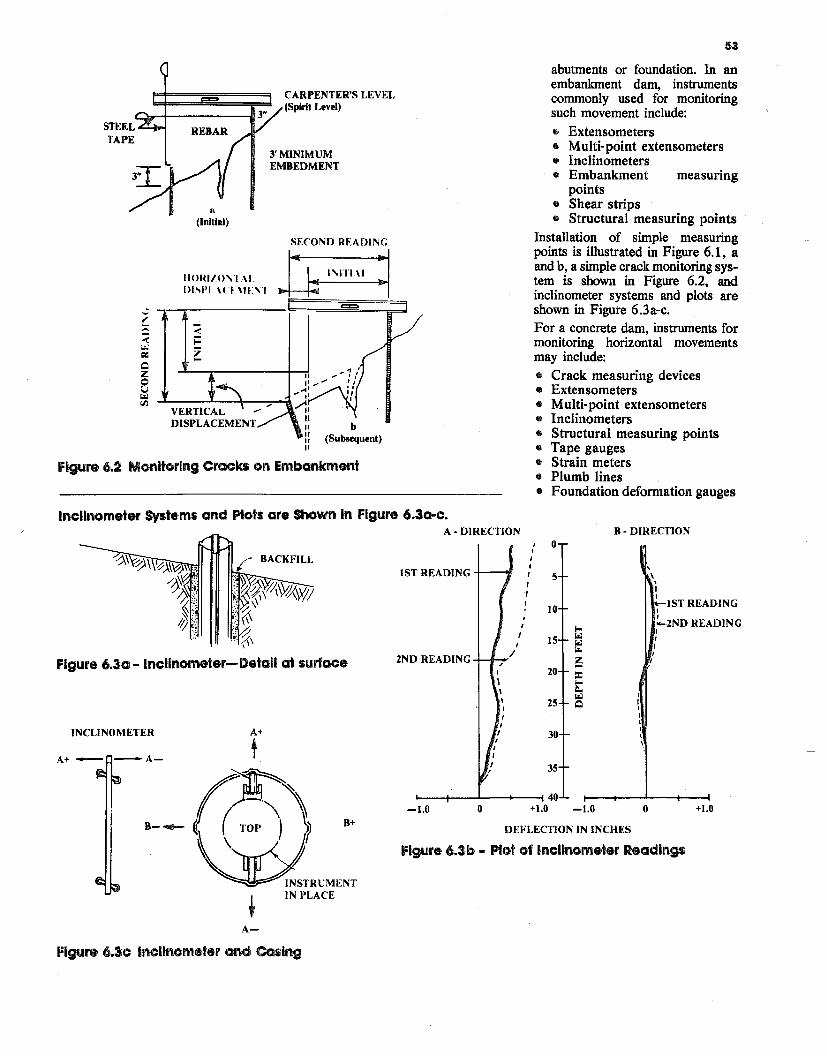
CARPENTER'S LEVEL (Spirit Level)
STEEL TAPE
3'MINIMUM EMBEDMENT
a (Initial)
SffOND READING
nl'\ITl\I :1llOHl/.O'\'I \I. _ -· l>ISl'I \( ~. \IF'\I
-.... "
II b :: (Subsequent) II
Figure 6.2 Monitoring Cracks on Embankment
F~TRUMENT IN PLACE
t A-
Figure 6.3c Inclinometer and Casing
Inclinometer Systems and Plots are Shown In Figure 6
IS
2NFigure 6.3a- lncllnometer-Delall at surface
INCLINOMETER A+
tA+- -A
(~ -B+B-411
igure
.3a-c
T REA
D REA
1.0
DEFLECTION IN INCHES
6.3b - Plot of Inclinometer Readings
. A • DIRECTION
I 0 I I I
DING I 5 I I
10 I ' !
I ~ I 15 ~
~/DING ~
20 ::c ! g,. ~
25 Q
30
35
40 0 +l.O -1.0
B • DIRECTION
\
\
IST READING I I -.2ND READING I I I I
I
I \
\.
0 +l.O
53
abutments or foundation. In an embankment dam, instruments commonly used for monitoring such movement include: • Extensometers • Multi-point extensometers • Inclinometers • Embankment measuring
points • Shear strips • Structural measuring points
Installation of simple measuring points is illustrated in Figure 6.1, a and b, a simple crack monitoring system is shown in Figure 6.2, and inclinometer systems and plots are shown in Figure 6.3a-c. For a concrete dam, instruments for monitoring horizontal movements may include: • Crack measuring devices • Extensometers • Multi-point extensometers • Inclinometers • Structural measuring points • Tape gauges • Strain meters • Plumb lines • Foundation deformation gauges
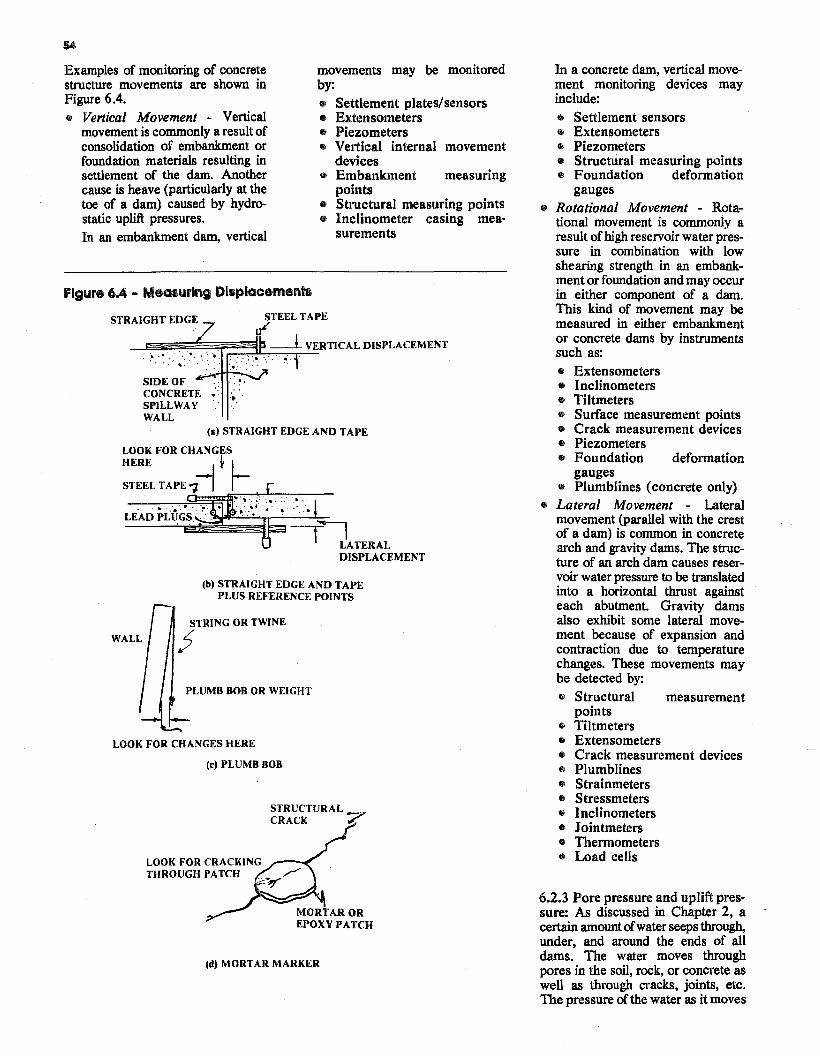
j
Figure 6.4 - Measuring Dlsplacements
STEEL TAPE STRAIGHT EDGE ul
_jg~~~~~~~ __l VERTICAL DISPLACEMENT . ·~ ; .......
. ~ .... , ..
SIDE OF CONCRETE •··. ·~ SPILLWAY WALL
(111) STRAIGHT EDGE AND TAPE
LOOK FOR CHANGES t HERE
STEEL TAPE-;z-1 ....• ..
'·' LEAD PLUGS. : .· :iao,paop::;.-..;~'-Fr-'--'--_.,..,..-
-~-,~~~~~at~ATERAL DISPLACEMENT
(b) STRAIGHT EDGE AND TAPE PLUS REFERENCE POINTS
STRING OR TWINE
PLUMB BOB OR WEIGHT
LOOK FOR CHANGES HERE
(c) PLUMB BOB
STRUCTURAL_ CRACK 7
LOOK FOR CRACKING THROUGH PATCH
Examples of monitoring of concrete movements may be monitored In a concrete dam, vertical movestructure movements are shown in by: ment monitoring devices may Figure 6.4. include:• Settlement plates/sensors • Vertical Movement - Vertical • Extensometers • Settlement sensors
movement is commonly a result of • Piezometers • Extensometers consolidation of embankment or • Vertical internal movement • Piezometers foundation materials resulting in devices • Structural measuring points settlement of the dam. Another • Embankment measuring • Foundation deformation cause is heave (particularly at the points gauges toe of a dam) caused by hydro • Structural measuring points • Rotational Movement - Rotastatic uplift pressures. • Inclinometer casing mea tional movement is commonly a
surementsIn an embankment dam, vertical result ofhigh reservoir water pressure in combination with low shearing strength in an embankment or foundation and may occur in either component of a dam. This kind of movement may bemeasured in either embankment or concrete dams by instruments such as: • Extensometers • Inclinometers • Tiltrneters• Surface measurement points • Crack measurement devices • Piezometers• Foundation deformation
gauges • Plumblines (concrete only)
• Lateral Movement - Lateralmovement (parallel with the crest of a dam) is common in concrete arch and gravity dams. The structure of an arch dam causes reservoir water pressure to be translated into a horizontal thrust against each abutment. Gravity dams also exhibit some lateral movement because of expansion and contraction due to temperature changes. These movements may be detected by: • Structural measurement
points • Tiltmeters • Extensometers • Crack measurement devices • Plumblines • Strainmeters • Stressmeters • Inclinometers• Jointmeters • Thermometers • Load cells
6.2.3 Pore pressure and uplift pres· sure: As discussed in Chapter 2, a certain amount of water seeps through, under, and around the ends of all dams. The water moves through
Id) MORT AR MARKER pores in the soil, rock, or concrete as well as through. cracks, joints, etc. The pressure of the water as it moves
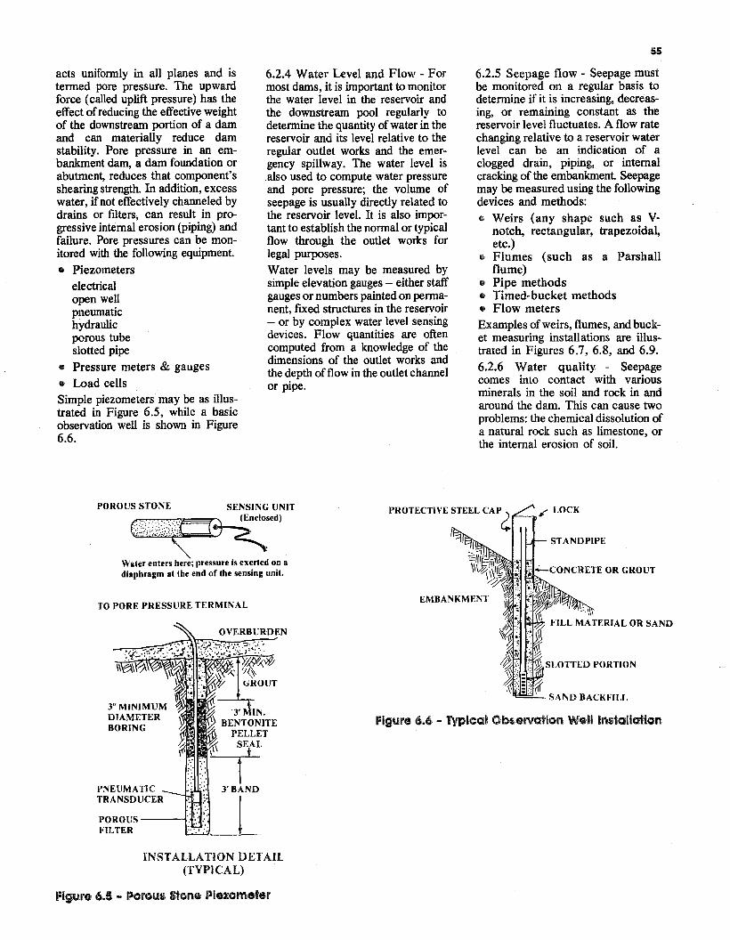
55
acts uniformly in all planes and is tenned pore pressure. The upward force (called uplift pressure) has the effect of reducing the effective weight of the downstream portion of a dam and can materially reduce dam stability. Pore pressure in an embankment dam, a dam foundation or abutment, reduces that component's shearing strength. In addition, excess water, if not effectively channeled by drains or filters, can result in progressive internal erosion (piping) and failure. Pore pressures can be monitored with the following equipment
• Piezometers electrical open well pneumatic hydraulic porous tube slotted pipe
• Pressure meters & gauges
• Load cells Simple piezometers may be as illustrated in Figure 6.5, while a basic observation well is shown in Figure 6.6.
6.2.4 Water Level and Flow - For most dams, it is important to monitor the water level in the reservoir and the downstream pool regularly to determine the quantity of water in the reservoir and its level relative to the regular outlet works and the emergency spillway. The water level is also used to compute water pressure and pore pressure; the volume of seepage is usually directly related to the reservoir level. It is also important to establish the normal or typical flow through the outlet works for legal purposes. Water levels may be measured by simple elevation gauges - either staff gauges or numbers painted on pennanent, fixed structures in the reservoir - or by complex water level sensing devices. Flow quantities are often computed from a knowledge of the dimensions of the outlet works and the depth offlow in the outlet channel or pipe.
6.2.5 Seepage flow - Seepage must be monitored on a regular basis to determine if it is increasing, decreasing, or remaining constant as the reservoir level fluctuates. A flow rate changing relative to a reservoir water level can be an indication of a clogged drain, piping, or internal cracking of the embankment Seepage may be measured using the following devices and methods: • Weirs (any shape such as V
notch, rectangular, trapezoidal, etc.)
• Flumes (such as a Parshall flume)
• Pipe methods • Timed-bucket methods • Flow meters Examples of weirs, flumes, and bucket measuring installations are illustrated in Figures 6.7, 6.8, and 6.9. 6.2.6 Water quality - Seepage comes into contact with various minerals in the soil and rock in and around the dam. This can cause two problems: the chemical dissolution of a natural rock such as limestone, or the internal erosion of soil.
POROUS STONE SENSING UNIT PROTECTIVE STEEL CAP~ #' LOCK ~nclosed)
14 STANDPIPE ~~ Water enters here; pressure is exerted on a diaphragm at the end of the sensing unit.
TO PORE PRESSURE TERMINAL EMBANKMENT
OVERBURDEN
3" MINIMUM DIAMETER Figure 6.6 - Typical Observation Well Installation BORING
PNEUMATIC TRANSDUCER
POROUS-----< FILTER
INSTALLATION DETAll (TYPICAL)
Figure 6.5 - Porous stone Piezometer
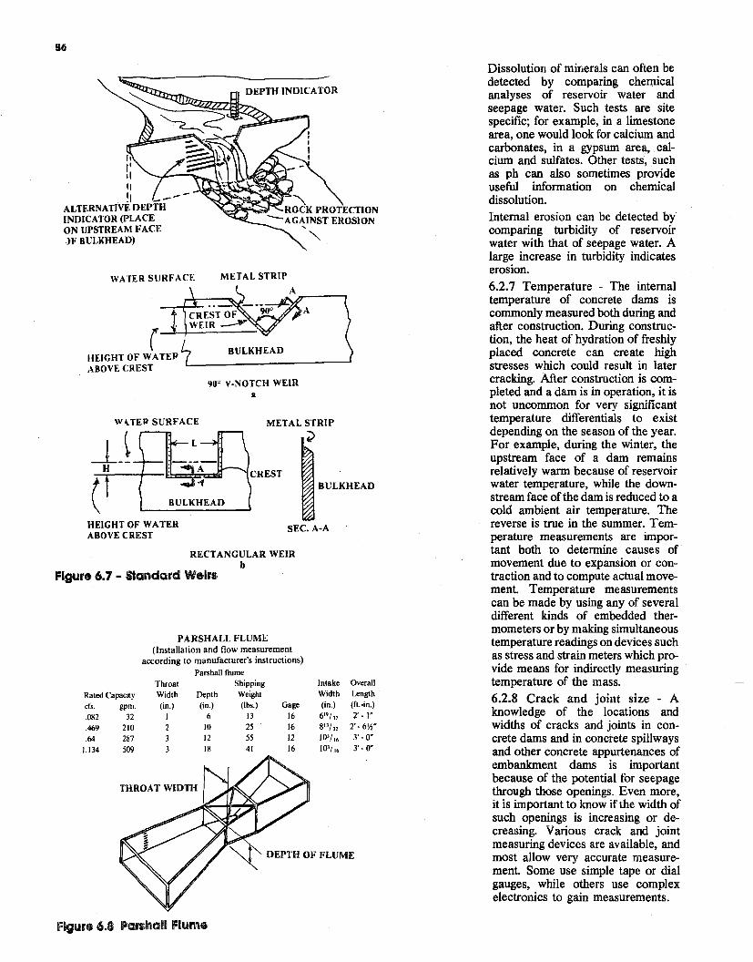
BULKHEAD
,, I',, ,, !I
ALTERNATIVE DEPTH INDICATOR (PLACE ON UPSTREAM FACE )F BULKHEAD)
METAL STRIPWATER SURFACE
A
( HEIGHT OF WA TEP ABOVE CREST
WHER SURFACE METAL STRIP
;>_LJ (
H
BULKHEAD
BULKHEAD
HEIGHT OF WATER SEC. A·A ABOVE CREST
RECTANGULAR WEIR b
Figure 6.7 - Standard Weirs
90'' V-NOTCH WEIR II
DEPTH INDICATOR
PARSHALL FLUME (Installation and flow measurement
according to manufacturer's instructions) Parshall flume
Throat Shipping Intake Overall
Rated Capacity Width Depth Weight Width Length
cfs. gpm. (in.) (in.) (lbs.) Gage (in.) (ft.-in.)
.082 32 I 6 13 16 619/,, 2'. 1·
.469 210 2 JO 25 16 813/ 32 2'·6W
.64 287 12 55 12 103/,. 3·. o· J.134 509 18 41 16 103/,. 3' - o·
THROAT WIDTH
DEPTH OF FLUME
Figure 6.8 Parshall Flume
Dissolution of minerals can often be detected by comparing chemical analyses of reservoir water and seepage water. Such tests are site specific; for example, in a limestone area, one would look for calcium and carbonates, in a gypsum area, calcium and sulfates. Other tests, such as ph can also sometimes provide useful information on chemical dissolution. Internal erosion can be detected by comparing turbidity of reservoir water with that of seepage water. A large increase in turbidity indicates erosion. 6.2.7 Temperature - The internal temperature of concrete dams is commonly measured both during and after construction. During construction, the heat of hydration of freshly placed concrete can create high stresses which could result in later cracking. After construction is completed and a dam is in operation, it is not uncommon for very significant temperature differentials to exist depending on the season of the year. For example, during the winter, the upstream face of a dam remains relatively warm because of reservoir water temperature, while the downstream face of the dam is reduced to a cold ambient air temperature. The reverse is true in the summer. Temperature measurements are important both to determine causes of movement due to expansion or contraction and to compute actual movement. Temperature measurements can be made by using any of several different kinds of embedded thermometers or by making simultaneous temperature readings on devices such as stress and strain meters which provide means for indirectly measuring temperature of the mass. 6.2.8 Crack and joint size - A knowledge of the locations and widths of cracks and joints in concrete dams and in concrete spillways and other concrete appurtenances of embankment dams is important because of the potential for seepage through those openings. Even more, it is important to know if the width of such openings is increasing or decreasing. Various crack and joint measuring devices are available, and most allow very accurate measurement Some use simple tape or dial gauges, while others use complex electronics to gain measurements.
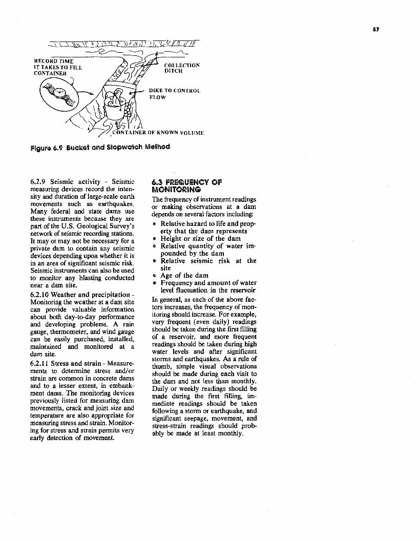
57
\\" 11\1)'1 \1, 't,.,1!/11} 1/'l/f --..__./'"\..._
COLLECTION DITCH
DIKE TO CONTROL FLOW
Figure 6.9 Bucket and Stopwatch Method
6.2.9 Seismic activity - Seismic measuring devices record the intensity and duration of large-scale earth movements such as earthquakes. Many federal and state dams use these instruments because they are part of the U.S. Geological Survey's network of seismic recording stations. It ~ay or may not be necessary for a pnvate dam to contain any seismic devices depending upon whether it is in an area of significant seismic risk. Seismic instruments can also be used to monitor any blasting conducted near a dam site. 6.2.10 Weather and precipitation Monitoring the weather at a dam site can provide valuable information about both day-to-day performance and developing problems. A rain gauge, thermometer, and wind gauge can be easily purchased, installed maintained and monitored at ~ dam site. 6.2.11 Stress and strain - Measurements to determine stress and/ or strain are common in concrete dams and to a lesser extent, in embankment dams. The monitoring devices previously listed for measuring dam movements, crack and joint size and temperature are also appropriate for measuring stress and strain. Monitoring for stress and strain permits very early detection of movement.
6.3 FREQUENCY OF MONITORING The frequency of instrument readings or making observations at a dam depends on several factors including:
• Relative hazard to life and property that the dam represents
• Height or size of the dam • Relative quantity of water im
pounded by the dam • Relative seismic risk at the
site • Age of the dam • Frequency and amount of water
level fluctuation in the reservoir In general, as each of the above factors increases, the frequency of monitoring should increase. For example, very frequent (even daily) readings should be taken during the first filling of a reservoir, and more frequent readings should be taken during high water levels and after significant storms and earthquakes. As a rule of thumb, simple visual observations should be made during each visit to the. dam and not less than monthly. Dady or weekly readings should be mad~ during the first filling, immediate readings should be taken following a storm or earthquake and significant seepage, movement: and stress-strain readings should probably be made at least monthly.
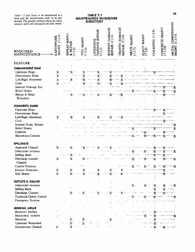
FEATURE
EMBANKMENT DAM Upstream Slope Downstream Slope Left/Right Abutments Crest Internal Drainage Sys. Relief Drains Riprap & Slope
Protection
x x x x
x
x
x
x x -x x
x
x x x x-
x
~-w» -x ··-x· x· x
x
·x
-x···
----·-x---------.
··--------x·~----x
--x------x----x ----·-·x---~
CONCRETE DAMS Upstream Slope Downstream Slope Left/Right Abutments Crest Internal Drain. System Relief Drains
x x x x x ······x
--x
.., .----x-·· ---x--
---··-x··~----
---
·--·--·----------·--x .--x·--··--· -----·--·-x
Galleries Sluiceways/Controls ·x
x·-··--·--···------·--x·--·-·---
-x- -----x-----···-X-'-----x
SPILLWAYS Approach Channel Inlet/ outlet structure Stilling Basin Discharge conduit/
Channel Control Features Erosion Protection Side Slopes
x
x
x x
x
x x
x x
x
x
x x
x
x x
x
x x
x x
x
x
x
---------x-··------x----------x-----------x----- -x------x
--·---x--- ----x- ·--------·x -x x '' ---x
x -x -x -----x - ------X""· -------
.·----·--x-·-------
OUTLETS & DRAINS Inlet/ outlet structure Stilling Basin Discharge Channel Trashrack/Debris Control Emergency Systems
x x x x x
x
x
x
x
' --x-- ·-x ----x -x x····-----x---x-.-x-·----·---··--·------x
GENERAL AREAS Reservoir Surface Mech/elect. systems Shoreline Upstream Watershed Downstream Channel x
x x x
x x
x
--x--'··:X: --- ------x-- ----- ----x
---x----------x--
-x---x---___J
--~~~,---
Table 7.1 lists items to be maintained at a TABLE 7.1 59
dam and the maintenance tasks to be per- MAINTENANCE GUIDELINES formed. The specific sections where the maintenance tasks are discussed are also noted.
DIRECTORY tf.l E--< z
REQUIRED MAINTENANCE
~;;0 r-: ~ '":' :I: E--<
~~ ~~
~ z-~~-~< ~~..-. ~~~ C2 ~ t:,
~ z-~ ci~ g:~._..
i:x:: ..... <ii..
~~ u Ill ~o tf.l < ..-. Ill~:; ~ 0 t:,
Ill 0 ~ ..-...x:"1 o~ E--< ._.. z~ Ill o~ ~~
Ill 0
~ G:o"':r-u ._.. ti: e$ J:I..<(
~~ E--<~
E--< z-~ :I: ..-. u r-: Ill "': ~t:
E--< z-~ E--<u..-. Ill::!; ...:i r-:Ill ._..
..-. ~ ...., t: 0 ~ ~ ~ u
E--<
~ < ~ Ill E--<
~..-. uo Z'"".o"': ut:
Ill z 0 ..-. i:i..~~ O"': ut: ...:i f-< <~
~~
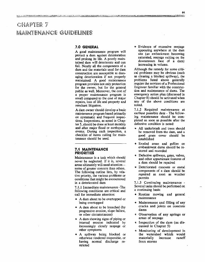
61
I
1.0 GENERAL A good maintenance program will protect a dam against deterioration and prolong its life. A poorly maintained dam will deteriorate and can fail. Nearly all the components of a dam and the materials used for dam construction are susceptible to damaging deterioration if not properly maintained A good maintenance program provides not only protection for the owner, but for the general public as well. Moreover, the cost of a proper maintenance program is small compared to the cost of major repairs, loss of life and property and resultant litigation. A dam owner should develop a basic maintenance program based primarily on systematic and frequent inspections. Inspections, as noted in Chapter 5, should be done at least monthly and after major flood or earthquake events. During each inspection, a checklist of items calling for maintenance should be used.
7.1 MAINTENANCE PRIORITIES Maintenance is a task which should never be neglected. If it is, several areas ultimately will need attention -some of greater concern than others. The following outline lists, by relative priority, the various problems or conditions that might be encountered in a deteriorated dam 7 .1.1 Immediate maintenance -The following conditions are critical and call for immediate attention: • A dam about to be overtopped or
being overtopped • A dam about to be breached (by
progressive erosion, slope failure, or other circumstances)
• A dam showing signs of piping or internal erosion indicated by increasingly cloudy seepage or other symptoms
• A spillway being blocked. or otherwise rendered inoperable, or having normal discharge restricted
e Evidence of excessive seepage appearing anywhere at the dam site (an embankment becoming saturated, seepage exiting on the downstream face of a dam) increasing in volume.
Although the remedy for some critical problems may be obvious (such as clearing a blocked spillway), the problems listed above generally require the services of a Professional Engineer familiar with the construction and maintenance of dams. The emergency action plan (discussed in Chapter 8) should be activated when any of the above conditions are noted. 7.1.2 Required maintenance at earliest possible date - The following maintenance should be completed as soon as possible after the defective condition is noted: • All underbrush and trees should
be removed from the dam, and a good grass cover should be established
• Eroded areas and gullies on embankment dams should be restored and reseeded
• Defective spillways, gates, valves, and other appurtenant features of a dam should be repaired
• Deteriorated concrete or metal components of a dam should be repaired as soori as weather permits
7 .1.3 Continuing maintenance Several tasks should be performed on a continuing basis: • Routine mowing and general
maintenance • Maintenance and filling of any
cracks and joints on concrete dams
• Observation of any springs or areas of seepage
• Inspection of the dam (as discussed in Chapter 5)
• Monitoring of development in the watershed which would materially increase runoff from storms
62
• Monitoring of development downstream and updating the emergency notification plan to include new homes or other occupied structures within the area
'1.2 SPECIFIC MAINTENANCE ITEMS 7 .2.1 Earthwork Maintenance and Repair - Deterioration of the surfaces of an earth dam may occur for several reasons. For example, wave action may cut into the upstream slope, vehicles may cause ruts in the crest or slopes, or runoff waters may leave erosion gullies on the downstream slope. Other special problems, such as shrinkage cracks or rodent damage, may also occur. Damage of this nature must be repaired on a continuing basis. The maintenance procedures described below are effective in repairing minor earthwork problems. However, this section is not intended to be a technical guide, and the methods discussed should not be used to solve serious problems. Conditions such as embankment slides, structural cracking, and sinkholes threaten the immediate safety of a dam and require immediate repair under the direction of an engineer. The material selected for repairing embankments depends upon the purpose of the earthwork. Generally, earth should be free from vegetation, organic materials, trash, or large rock. Most of the earth should be fine-grained soils or earth clods which easily break down when worked with compaction equipment. The intent is to use a material which, when compacted, forms a firm, solid mass, free from excessive voids. If flow-resistant portions of an embankment are being repaired, materials which are high in clay or silt content should be used. If the area is to be free draining or highly permeable (i.e., riprap bedding, etc.) the material should have a higher percentage of sand and gravel. As a general rule, it is usually satisfactory to replace or repair damaged areas with soils similar to those originally in place. An important soil property affecting compaction is moisture content. Soils which are too dry or too wet do not compact well. One may roughly test repair material by squeezing it
into a tight ball. If the sample maintains its shape without cracking and failing apart (which means it is too dry), and without depositing excess water onto the hand (which means it is too wet), the moisture content is probably near the proper level. Before placement of earth, the repair area must be prepared by removing all inappropriate material. Vegetation such as brush, roots, and tree stumps must be cleared and any large rocks or trash removed. Also, unsuitable earth, such as organic or loose soils, should be removed, so that the work surf ace consists ofexposed firm clean embankment material. Following clean-up, the affected area should be shaped and dressed, so that the new fill can be compacted and will properly tie into the existing fill. Ifpossible, slopes should be trimmed, and surfaces roughened by scarifying or plowing to improve the bond between the new and existing fill and to pro~de a good base to compact agamst. Soils should be placed in loose layers up to 8 inches thick and compacted manually or mechanically to form a dense mass free from large rock or organic material. Soil moisture must be maintained in the proper range. The fill should be watered and mixed to the proper wetness or scarified and allowed to dry if too wet. During backfilling, care should be taken that fill does not become too · wet from rainstorm runoff. Runoff should be directed away from the work area and repair areas should be overfilled so that the fill maintains a crown which will shed water. As mentioned eariler, occasionally minor cracks will form in an earth dam because of surface drying. These are called dessication (drying) cracks and should not be confused with structural or settlement cracks. Drying cracks are usually parallel to the main axis of the dam, typically near the upstream or downstream shoulders of the crest These cracks often run intermittently along the length of the dam and may be up to 4 feet deep. Drying cracks can be distinguished from more serious structural cracks because the former are usually no wider than a few inches and have edges that are not offset vertically.
As a precaution, suspected drying cracks should initially be monitored
with the same care used for structural cracks: The problem area should be marked with survey stakes, and monitoring pins should be installed on either side of the crack to allow recording of any changes in width or vertical offset Once satisfied that observed cracking is the result of shrinkage or drying, an owner may stop monitoring. ' However, these cracks will close as climatic or soil moisture conditions change. H they do not, it may be necessary to backfill the cracks to prevent entry of surface moisture which could result in saturation ofthe dam. The cracks may be simply filled ~th earth that is tamped in place with hand or tools. It is also recommended that the crest of a dam be graded to direct runoff waters away from areas damaged by drying cracks. As Chapter 5 suggests, erosion is one of the most common maintenance problems at embankment structures. Ero~ion is a natural process, and its continuous forces will eventually wear down almost any surface or structure. Periodic and timely maintenance is essential to prevent continuous deterioration and possible failure.
Sturdy sod, free from weeds and brush, is an effective means of preventing erosion. Embankment slopes are nonnally designed and constructed so that surface drainage will be spread out in thin layers (sheet flow) on the grassy cover. When embankment sod is in poor condition or flows are concentrated at any location the resulting erosion will leave rills' and gullies in the embankment slope. An owner should look for such areas and be aware of the problems that may develop. Eroded areas must be promptly repaired to prevent more serious damage to the embankment. Rills and gullies should be filled with suitable soil (the upper 4 inches should be top soil, if possible,) compacted, and then seeded. A local Soil Conservation Service Officer can be very helpful in selecting the types of grass to use for dam surface protection. Erosion in large gullies can be slowed by stacking bales of hay or straw across the gully until permanent repairs can be made. Not only should eroded areas be repaired, but the cause of the erosion should be found to prevent a continuing maintenance problem. Erosion
63
might be caused or aggravated by improper drainage, settlement, pedestrian traffic, animal burrows, or other factors. The cause of the erosion will have a direct bearing on the type of repair needed Paths due to pedestrian or two-wheel and four-wheel vehicle traffic are a problem on many embankments. If a path has become established, vegetation will not provide adequate protection and more durable cover will be required unless traffic is eliminated. Small stones, asphalt, or concrete may be used effectively to cover footpaths. In addition, railroad ties or other treated wood beams can be embedded into an embankment slope to form an inexpensive stairway. Erosion is also common at the point where an embankment and the concrete walls of a spillway or other structure meet. Poor compaction adjacent to such a wall during construction and subsequent settlement can result in an area along the wall lower than the grade of the embankment. Runoff, therefore, often concentrates along these structures, resulting in erosion. People also frequently walk along these walls, wearing down the vegetal cover. Possible solutions include regrading the area so that it slopes away from the wall, adding more resistant surface protection, or constructing wooden steps. Adequate erosion protection is also needed along the contact between the downstream face of an embankment and the abutments. Runoff from rainfall can concentrate in gutters constructed in these areas and can reach erosive velocities because ofrelatively steep slopes. Berms on the downstream face that collect surface water and empty into these gutters add to the runoff volume. Sod-surfaced gutters may not adequately prevent erosion in these areas. Paved concrete gutters may not be desirable either because they do not slow the water and can be undermined by erosion. Also, small animals often construct burrows underneath these gutters adding to the erosion potential. A well-graded mixture of rocks up to 9 to 12 inches in diameter (or larger) placed on a layer of sand (filter) generally provides the best protection for these gutters on small dams. Riprap slushed with a thin concrete slurry has also been successful in preventing erosion on larger dams and should be used if large stone material is not available.
As with erosion around spillways, erosion adjacent to gutters results from improper construction or a poor design in which the finished gutter is too high with respect to adjacent ground. This condition prevents much of the runoff water from entering the gutter. Instead, the flow concentrates along the side of the gutter, erodes and may eventually undermine the gutter. Care should be taken when replacing failed gutters or designing new gutters to assure that • The channel has adequate
capacity • Adequate erosion protection and
a satisfactory filter have been provided
• Surface runoff can easily enter the gutter
• The outlet is adequately protected from erosion
7 .2.2 Riprap maintenance and repair - A serious erosion problem called "beaching" can develop on the upstream slope of a dam. Waves caused by high winds or high-speed boats can erode the exposed face of an embankment by repeatedly striking the surface just above the pool elevation, rushing up the slope, then tumbling back into the pool. This action erodes material from the face of the embankment and displaces it down the slope, creating a "beach." Erosion of unprotected soil can be rapid and, during a severe storm, could lead to complete failure of a dam. The upstream face of a dam is commonly protected against wave erosion and resultant beaching by placement on the face of a layer of rock riprap over a layer of filter material. Sometimes, materials such as steel, bituminous or concrete facing, bricks or concrete blocks are used for this upstream slope protection. Protective beaches are sometimes actually built into small dams by placing a berm ( 8 to 10 feet wide) along the upstream face a short distance below the normal pool level thereby providing a surface on which wave energy can dissipate. Generally, however, rock riprap provides the most economical and effective protection. Nonetheless, beaching can occur in existing riprap if the embankment surface is not properly protected by a filter. Water running down the slope
under the riprap can erode the embankment. Sections of riprap which have slumped downward are often signs of this kind of beaching. Similarly, concrete facing used to protect slopes may fail because waves wash soil from beneath the slabs through joints and cracks. Detection of this problem is difficult because the voids are hidden and failure may be sudden and extensive. Effective slope protection must prevent soil from being removed from the embankment When erosion occurs and beaching develops on the upstream slope of a dam, repairs should be·made as soon as possible. The pool level should be lowered and the surface of the dam prepared for repair. A small berm or "bench" should be built across the face of the dam at the base of the new layer of protection to help hold the layer in place. The size of the bench needed depends on the thickness of the protective layer. A riprap layer should extend a minimum of 3 feet below the lowest expected normal pool level. Otherwise, wave action during periods of low lake level will undermine and destroy the protection. If rock riprap is used, it should consist of a heterogeneous mixture of irregular shaped stone placed over a sand and gravel filter. The largest rock must be large enough in both size and weight to break up the energy of the maximum expected waves and hold smaller stones in place. (An engineer may have to be consulted to determine size.) The smaller rocks help to fill the spaces between the larger pieces and to form a stable mass. The filter prevents soil particles on the embankment surface from being washed out through the spaces between the rocks in the ri~ rap. If the filter material itself can be washed out through these voids and beaching develops, two layers of filters may be required. The lower layer should be composed of sand or filter fabric to protect the soil surface and the upper layer should be composed of coarser materials. A dam owner should expect some riprap deterioration because of weathering. Freezing and thawing, wetting and drying, abrasive wave action and other natural processes will eventually break down the material. Therefore, sufficient maintenance funds should be allocated for the regular replacement of riprap.
64
The useful life of riprap varies depending on the characteristics of the stone used. Thus, stone for riprap should be rock that is dense and well cemented When riprap breaks down, and erosion and beaching occur more often than once every three to five years, professional advice should be sought to design more effective slope protection.
7.2.3 Vegetation maintenance-The entire dam should be kept clear of unwanted vegetation such as brush or trees. Excessive growth may cause several problems:
• It can obscure the surface of an embankment and prevent a thorough inspection of the dam
• Large trees can be uprooted by high wind or erosion and leave large holes, that can lead to breaching of the dam
• Some root systems can decay and rot, providing passageways for water, and thus causing erosion
• Growing root systems can lift concrete slabs or structures
• Weeds can prevent the growth of desirable grasses
• Rodent habitats can develop When brush is cut down, it should be removed from a dam to permit a clear view of the embankment. Following removal of large brush or trees, the left over root systems should also be removed if possible and the resulting holes properly filled In cases where they cannot be removed, root systems can be treated with herbicide (properly applied) to retard further growth. After the removal of brush, cuttings may need to be burned. If this is done, dam owners should notify the local fire department, forest service, or other agency responsible for fire control.
If properly maintained, grass is not only an effective means ofcontrolling erosion, it also enhances the appearance of a dam and provides a surface that can be easily inspected Grass roots and stems tend to trap fine sand and soil particles, forming an erosionresistant layer once the plants are well established. Grass is least eff ective in areas ofconcentrated runoff or in areas subjected to wave action.
7 .2.4 Livestock control - Livestock should not be allowed to graze on an embankment surface. When soil is wet, they can damage vegetation and destroy the uniformity of the surface.
Moreover, livestock tend to walk in established paths and thus can promote severe erosion. Such paths should be regraded and seeded, and the livestock should be pennanently fenced out of the area.
7 .2.5 Rodent damage control Rodents, such as groundhogs (woodchucks), muskrats, and beavers are naturally attracted to the habitats created by dams and reservoirs and can, by their behavior, endanger the structural integrity and proper performance ofembankments and spillways. Groundhog and muskrat burrows can weaken embankments and can serve as pathways for seepage. Beavers can plug a spillway and raise the pool level. Rodent control is essential to the preservation of a dam. The groundhog is the largest member of the squirrel family. Its coarse fur is a typically grayish brown with a reddish cast. Occupied groundhog burrows are easily recognized in the spring because of the groundhog's habit of keeping them "cleaned out." Fresh soil is generally found at the mouth of such active burrows. Halfround mounds, paths leading from the den to nearby fields, and clawed or girdled trees and shrubs also indicate inhabited burrows and dens.
When burrowing into an embankment, groundhogs stay above the phreatic surface (upper surface of seepage or saturation) to stay dry. The burrow is rarely a single tunnel. It is usually forked, with more than one entrance and with several side passages or rooms from 1 to 12 feet in length.
Controls should be implemented during early spring when active burrows are easy to find, young groundhogs have not yet scattered, and there is less likelihood of damage to other wildlife. In summer, fall, and winter, game animals may scurry into groundhog burrows for brief protection and may even take up permanent residence during the period of groundhog hibernation.
Groundhogs can be controlled with fumigants or firearms. Fumigation is the most practical method although around buildings or high fire hazard areas, shooting may be preferable. Gas cartridges for fumigation may be purchased at local farm exchanges, farm supply centers, and many county extension offices.
Groundhogs will be discouraged from inhabiting an embankment ifthe grass cover is kept mowed. ·
The muskrat is a stocky rodent with a broad head, short legs, small eyes, and rich dark brown fur. Muskrats are chiefly nocturnal and can be found wherever there are marshes, swamps, ponds, lakes, and streams having calm or very slowly moving water with vegetation in the water and along the banks. Barriers, such as properly constructed riprap and filter layers, provide the most practical protection from muskrats by preventing burrowing. As a muskrat tries to construct a burrow, the sand and gravel ofa filter layer will cave in and discourage den building. Filter layers and riprap should extend at least 3 feet below water line. Heavy wire fencing laid flat against a slope and extending above and below the waterline can also be effective. Eliminating or reducing aquatic vegetation along a shoreline will also discourage muskrat habitation. Trapping with steel traps is normally the most practical method ofremoving muskrats that have already inhabited a pond.
The easily recognized beaver, if inhabiting an area around a dam, will try to plug the spillway with their cuttings. Routinely removing the cuttings can alleviate the problem or an electrically charged wire or wires can be placed around the spillway inlet. Beaver may be trapped during the proper season and sometimes a local fur trapper will perform the work at little or no expense to the owner.
Methods of repairing rodent damage depend upon the nature ofthe damage, but in any case, extermination of the rodent population is the required first step. Ifthe damage consists mostly of shallow holes scattered across an embankment, repair may be necessary to maintain the appearance of the dam, to keep runoff waters from infiltrating the dam, or to discourage rodents from subsequently returning to the embankment. In these cases, tamping of earth into the rodent hole should be sufficient repair. Soil should be placed as deeply as possible and compacted with a pole or shovel handle.
Large burrows on an embankment should be filled by mud-packing. This simple, inexpensive method involves placing one or two lengths of metal stove or vent pipe vertically over the entrance of the den with a tight seal
between the pipe and den. A mudpack mixture is then poured into the pipe until the burrow and pipe are filled with the earth-water mixture. The pipe is removed and additional dry earth is tamped into the entrance. The mud-pack mixture is made by adding water to a 90 percent earth and 10 percent cement mixture until a slurry of thin cement is attained. All entrances should be plugged with well-compacted earth and vegetation re-established. Dens should be eliminated promptly because one burrow can lead to failure of a dam. Different repair measures are necessary if a dam has been damaged by extensive small rodent tunneling or by beaver or muskrat activity. In these cases, it may be necessary to excavate the damaged area down to competent soil and repair as described in Section 7.2.1. Occasionally, rodent activity will result in passages which extend through the embankment that could result in leakage of reservoir water, piping, and, ultimately, failure. In these cases, the downstream end of the tunnel should not be plugged since this will add to the saturation of the dam. Tunnels of rodents or ground squirrels will normally be above the phreatic surface with primary entrance on the downstream side ofthe dam, while those ofbeaver and muskrat normally exist below or at the water surface with entrance on the upstream slope. Ifa rodent hole is found that extends through the dam, the best procedure is first to locate the upstream end ofthe passage. The area around the entrance should be excavated and then backfilled with impervious material. This places a plug or patch at the passage entrance so that reservoir water is prevented from saturating the interior of the dam. This should be considered a temporary repair. Excavation and backfilling of the entire tunnel or filling of the tunnel with cement grout are possible long-term solutions, but pressure cement grouting is an expensive and sometimes dangerous procedure. Indeed, pressure exerted during grouting can cause additional damage to the embankment in the form of hydraulic fracturing (an opening of cracks by high pressure grouting). Thus, grouting should be performed only under the direction of an engineer.
7 .2.6 Traffic damage control - As mentioned eariler, vehicles driving across an embankment dam can create ruts in the dam crest if the crest is not surfaced with roadway material. The ruts can then collect water and cause saturation and softening of the dam. Other ruts may be formed by vehicles driving up and down a dam face. These ruts can collect runoff and result in severe erosion. Vehicles should be banned from dam slopes and kept out by fences or barricades. Any ruts should be repaired as soon as possible using the methods outlined in Section 7 .2.1. 7 .2. 7 Mechanical maintenance Proper operation of a dam's outlet works is essential to the safe and satisfactory operation of a dam. Release of water from a dam is normally a frequent or ongoing function. However, on some reservoirs used for recreation, fish propagation, or other purposes that do not require continual release of water, an operable outlet provides the only means for the emergency lowering of the reservoir and is therefore, essential for the safety of the dam. If routine inspection of the outlet works indicates the need for maintenance, the work should be completed as soon as access can be gained. Postponement of maintenance could cause damage to the installation, significantly reduce the useful life of the structure, and result in more extensive and more costly repairs when finally done. More importantly, failure to maintain an outlet system can lead directly to failure of the dam. The simplest procedure to insure the smooth operation of outlet gates is to operate all gates through their full range at least once and preferably twice annually. Many gate manufacturers recommend operating gates as often as four times a year. Because operating gates under full reservoir pressure can result in large outlet discharges, gate testing should be scheduled during periods of low storage. If this cannot be done, they should be operated during periods of low stream flow. If large releases are expected, outlets should be tested only after coordinating releases with water administration officials and notifying downstream residents and water users.
Operation of the gates minimizes the buildup of rust in the operating mechanism and therefore, the likelihood of seizure of the operating mechanism. During this procedure, the mechanical parts of the hoisting mechanism - including drive gears, bearings, and wear plates - should be checked for adverse or excessive wear, all bolts, including anchor bolts, should be checked for tightness, worn and corroded parts should be replaced, and mechanical and alignment adjustments should be made as necessary. The way the gate actually operates should also be noted Rough, noisy, or erratic movement could be the first signs of a developing problem. The cause ofoperational problems should be investigated and corrected immediately. Excessive force should be neither needed nor applied to either raise or lower a gate. Most hoisting mechanisms are designed to operate satisfactorily with a maximum force of 40 pounds on the operating handle or wheel. If excessive force seems to be needed, something may be binding the mechanical system. The application of excessive force may result in increased binding of the gate or damage to the outlet works. If there does seem to be undue resistance, the gate should be worked up and down repeatedly in short strokes until the binding ceases, and/or the cause of the problem should be investigated Of course, the problem should be corrected as soon as possible to assure the continued operability of the gate. If a gate does not properly seal when closed, debris may be lodged under or around the gate leaf or frame. The gate should be raised at least 2 to 3 inches to flush the debris, and the operator should then attempt to reclose the gate. This procedure should be repeated until proper sealing is achieved However, if this problem or any other problem persists, a manufacturer's representative or engineer experienced in gate design and operation should be consulted. An outlet gate operating mechanism should always be well lubricated in accordance with manufacturer's specifications. Proper lubrication will not only reduce wear in the mechanism, but also protect it against adverse weather. Gates with
oil-filled stems (i.e., stems encased in a larger surrounding pipe) should be checked semiannually to assure the proper oil level is maintained. If such mechanisms are neglected, water could enter the encasement pipe through the lower oil seal and could cause failure of the upper and/or lower seals which in tum could lead to the corrosion of both the gate stem and interior of the encasement pipe. The metal used in gate seats is usually brass, stainless steel, bronze, or other rust-resistant alloys. Older or smaller gates may not be fitted with seats, making them susceptible to rusting at the contact surfaces between the gate leaf and gate frame. Operation of gates should prevent excessive rust buildup or seizure. For satisfactory operation, a gate stem must be maintained in proper alignment with the gate and hoisting mechanism. Proper alignment and support is supplied by stem guides in sufficient number and properly spaced along the stem. Stem guides are brackets or bearings through which a stem passes. They both prevent lateral movement of the stem and bending or buckling when a stem is subjected to compression as a gate is being closed. The alignment of a stem should be checked during routine inspections. Alignment may be checked by sighting along the length of the stem, or more accurately by dropping a plumbline from a point near the top of the stem to the other end. The stem should be checked in both an upstream/downstream direction as well as in a lateral direction to ensure straightness. While checking alignment, all gate stem guide anchors and adjusting bolts should be checked for tightness. A loose guide provides no support to the stem and could caus~ buckling of the stem at that point. Ifduring normal inspection, the stem appears out of alignment, the cause should be repaired The gate should be completely lowered and all tension or compression taken off the stem. Any misaligned stem guides should be loosened and made to move freely. The hoisting mechanism should then be operated to put tension on the stem, thereby straightening it, but the gate should not be opened. The affected guides should then be aligned and fastened so that the stem passes exactly through their centers.
Many outlet gates are equipped with wedges that hold the gate leaf tightly against the gate frame as the gate is closed, thus causing a tight seal. Through years of use, gate seats may become worn, causing the gate to leak increasingly. If an installation has a wedge system, the leakage may be substantially reduced or eliminated by readjusting the wedges. Because adjustment of these gates is complicated, inexperienced personnel can cause extensive damage to a gate. Improper adjustment could cause premature seating of the gate, possible scoring of the gate seats, binding of the gate, gate vibration, leakage, uneven closing of the gate, or damage to wedges or gate guides. Thus, only experienced personnel should perform adjustments, and a gate supplier or manufacturer should be consulted to obtain names of people experienced in such work. Ice can exert great force on and cause significant damage to an outlet gate leaf. Storage levels in a reservoir during winter should be low enough that ice cannot form behind a gate. To prevent ice damage, the winter water level should be significantly higher than the gate if storage is maintained through the winter or, if the reservoir is to remain empty over the winter months, the outlet should be left fully open. If operations call for the water level to move across the gate during the winter, a bubbler or other anti- · icing system may be needed. 7 .2.8 Electrical maintenance Electricity is typically used at a dam to: e Provide lighting • Operate outlet gates • Operate recording equipment • Operate spillway gates • Operate other miscellaneous
equipment It is important that an electrical system be well maintained. Maintenance should include a thorough check of fuses and a test of the system to ensure that all parts are properly functioning. The electrical system should be free from moisture and dirt, and wiring should be checked for corrosion and mineral deposits. Any necessary repairs should be completed immediately, and records of the repair work should be kept. Generators used for auxiliary emergency power must also be maintained. This work includes changing oil, checking batteries and antifreeze
and ensuring that fuel is readily available. 7 .2.9 Cleaning - As already suggested, the proper operation of spillways, sluiceways, approach channels, inlet/outlet structures, stilling basins, discharge conduit, dam slopes, trashracks, and debris control devices require regular and thorough debris removal and cleaning. Cleaning is especially important after upstream storms which tend to send more debris into the reservoir. 7 .2.10 Concrete maintenance Also as mentioned, periodic maintenance should be performed on all concrete surfaces to repair deteriorated areas. Concrete deterioration should be repaired immediately when noted; it is most easily repaired in its early stages. Deterioration can accelerate and, ifleft unattended, can result in serious problems or dam failure. An experienced engineer should be consulted to determine both the extent of deterioration and the proper method of repair. 7 .2.11 Metal component maintenance - All exposed, bare ferrous metal on an outlet installation, whether submerged or exposed to air, will tend to rust. To prevent corrosion, exposed ferrous metals must either be painted or heavily greased. If painted, the paint should be appropriate and applied following the paint manfacturer's directions. When areas are repainted, steps should be taken to assure that paint does not get on gate seats, gate wedges, or gate stems where the stems pass through the stem guides, or on other friction surfaces where paint could cause binding. Heavy grease should be used on surfaces where binding can occur. Because rust is especially damaging to contact surfaces, existing rust should be removed before the periodic application of grease.
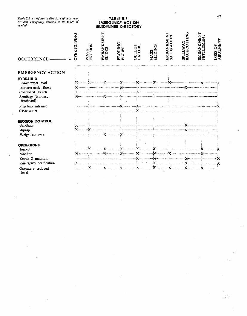
E-<~ ~ ~o ~z >< f-"' z ~ 0 0 ~f::: <f-"' ~~ E-< lil0 ~Cf.l
TABLE 8.1 EMERGENCY ACTION
GUIDELINES DIRECTORY
f-"' 0 E-<z ~z z .......
0 z ~ ~ ~ 0
~ ....... ~~ ~::> Cf.l~ ~~ ~8 ~~ ~~ ~ >Cf.l Q~ ...l ...l ~ ::> :J~ ~ ~o 5...... Cf.l0 ,_.U ~ ::> > ~:l ~g ~~ ~< ~!:
~~~- 0 ~ffi ~Cf.l ~~ o~ ~@ ~Cf.l Cf.l~ ~~ 9~
ON
X: ·· ·--·X· ··-·-:X
·-:X· .. x ···X··
x ·x · ·--x········· ········-·· --····-·-··--x ···X-· X··················X······· ·····X·············· ·-~X-····· ----K-·····-······
CCURRENCE
MERGENCY ACTI
free board)
lug leak entrance lose outlet
OSION CONTROL
PERATIONS nspect
onitor epair & maintain mergency notification
perate at reduced level
DRAULIC ower water level
ncrease outlet flows ontrolled Breach andbags (increase
andbags iprap eight toe area
O
E
PC
ER
OIMRE
O
HYLICS
SRW
K·-x-~
X-·· X·-·
X··· X··-- -K-··
.... ·····-· ········. ~···-···---x- -·-·-·-7<: -···-·· --~:x~-~-
····-·· --····--·X··········· ···X·······
67 Table 8.1 is a reference directory ofoccu"ences and emergency actions to be taken if needed.
69
8.0 THE EMERGENCY ACTION PLAN Although most dam owners have a high level of confidence in the structures they own and are certain their dams will not fail, history has shown that on occasion dams do fail and that often these failures cause extensive property damage and deaths. A dam owner should prepare for this possibility by developing an emergency action plan which provides a systematic means to:
• Identify emergency conditions threatening a dam
• Expedite effective response actions to prevent failure
• Reduce loss of life and property damage should failure occur
A dam owner is responsible for preparing a plan stating the above purposes and listing actions that the owner, the operating personnel and local government authorities should take. A plan should include sections on: Purpose: (indicated above)
Situation: • A list of problem indicators (see
the checklist included in Table 8.3)
• A summary of communities in the potential inundation zone and flood travel times
• A list of anticipated failure situations that can be used as a guide for appropriate responses such as:
• Failure pending- structure can likely be saved with immediate remedial action
• Failure imminent - structure may possibly be saved with immediate remedial action
• Failure in progress - no chance to save the structure
• Flooding expected or in progress upstream from the dam site
• Any other conditions peculiar to this dam
Execution: • A list of remedial actions to pre
vent failure (see Section 8.2.) • A plan for notification of down
stream communities that allows the greatest possible time to warn and evacuate residents should failure occur and a list of telephone numbers of emergency preparedness officials in each community (There is an important distinction between notification and warning. Notification is the responsibility of the dam owner; he or she must notify community emergency officials of impending failure. These officials must then warn the public and evacuate them from the inundation zone if necessary. Public warning processes need not be fully specified in the dam owners' emergency action plan.)
Resources and Coordinating Instructions:
• A list of those who can be of assistance, related telephone numbers, and radio call signs
• A list of materials for use in remedial action; for example, sandbags, high intensity lighting for night repairs
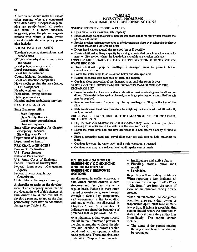
70
A dam owner should make full use of other persons who are concerned with dam safety. Cooperative planning can greatly benefit all parties and result in a more concrete, integrated, plan. People and organizations with whom a dam owner should coordinate emergency planning include: LOCAL PARTICIPANTS The dam's owners, shareholders, and
beneficiaries Officials of nearby downstream cities
and towns Local police, county sheriff Local emergency officials Local fire department County highway department Local construction companies News media serving the area (radio,
TV, newspaper) Nearby engineering firms Professional diving services Helicopter services Hospital and/or ambulance services STATE AGENCIES State Engineers office
State Engineer Dam Safety Branch Local water commissioner Division engineer
State office responsible for disaster emergency services State Highway Patrol
Department of highways Department of health FEDERAL AGENCIES Bureau of Reclamation U.S. Forest Service National Park Service U.S. Army Corps of Engineers Federal Bureau of Investigation Federal Emergency Management
Agency Federal Energy Regulatory
Commission United States Geological Survey A checklist to assist in the development of an emergency action plan is provided at the end of this chapter. A dam owner should use this list to develop a plan and to update the plan periodically thereafter as conditions change (see Table 8.3).
TA.BU! 8.2 POTENTIAL PROBLEMS
AND IMMEDIATE RESPONSE ACTIONS
OVERTOPPING BY FLOOD WATERS o Open outlet to its maximum safe capacity o Place sandbags along the crest to increase freeboard and force more water through the
spillway and outlet • Provide erosion-resistant protection to the downstream slope by placing plastic sheets
or other materials over eroding areas • Divert flood waters around the reservoir basin if possible • Create additional spillway capacity by making a controlled breach in a low embank
ment or dike section where the foundation materials are erosion resistant LOSS OF FREEBOARD OR DAM CROSS SECTION DUE TO STORM WAVE EROSION • Place additional riprap or sandbags in damaged areas to prevent further
embankment erosion • Lower the water level to an elevation below the damaged area • Restore freeboard with sandbags or· earth and rocldill • Continue close inspection of the damaged area until the storm is over SLIDES ON THE UPSTREAM OR DOWNSTREAM SLOPE OF THE EMBANKMENT • Lower the water level at a rate and to an elevation considered safe given the slide con
dition. If the outlet is damaged or blocked, pumping, siphoning, or a controlled breach may be required
• Restore lost freeboard if required by placing sandbags or filling in the top of the slide
• Stabilize slides on the downstream slope by weighting the toe area with additional soil, rock, or gravel
EROSIONAL FLOWS THROUGH THE EMBANKMENT, FOUNDATION, OR ABUTMENTS • Plug the flow with whatever material is available (hay bales, bentonite, or plastic
sheeting if the entrance to the leak is in the reservoir basin) • Lower the water level until the flow decreases 'to a non-erosive velocity or until it
stops • Place a protective sand and gravel filter over the exit area to hold materials in
place • Continue lowering the water level until a safe elevation is reached • Continue operating at a reduced level until repairs can be made
8.1 IDENTIFICATION OF EMERGENCY CONDITIONS AND INITIATION OF EMERGENCY RESPONSE ACTIONS AB discussed in earlier chapters, a dam owner should observe a dam structure and the dam site on a regular basis. Failure is most oft.en caused by overtopping, water flowing through a dam's key components, and weaknesses in the foundation and outlet works. As discussed in Chapters S and 6, a number of indicators can signal the beginning of problems that might cause failure. At a minimum, a dam owner should include in the "Situation" portion of the plan a reminder to check the history and location of hazards which could lead to overtopping or other acute problems. These are discussed in detail in Chapter 3 and include:
• Earthquakes and active faults • Flooding, storms, snow melt
runoff • Landslides Reporting a Dam S8.fety Incident When reporting a dam incident, all directions for example "left of'' or "right from") are from the point of view of an observer facing downstream.
When an "indicator" or dangerous condition appears, a dam owner or responsible agent must take immediate action. If failure is possible, that person should report the situation to state and local dam safety authorities immediately. The report should include: • The name of the person making
the report and how he or she can be contacted
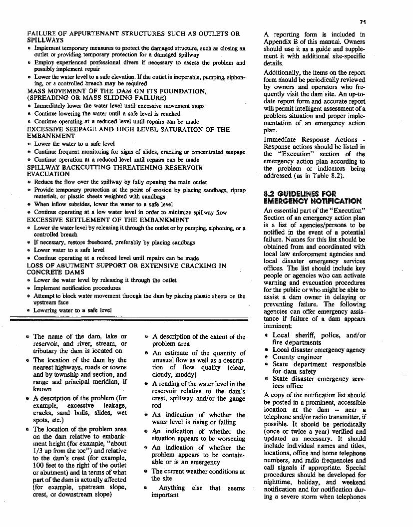
71
FAILURE OF APPURTENANT STRUCTURES SUCH AS OUTLETS OR SPILLWAYS • Implement temporary measures to protect the damaged structure, such as closing an
outlet or providing temporary protection for a damaged spillway • Employ experienced professional divers if necessary to assess the problem and
possibly implement repair • Lower the water level to a safe elevation. If the outlet is inoperable, pumping, siphon
ing, or a controlled breach may be required MASS MOVEMENT OF THE DAM ON ITS FOUNDATION, (SPREADING OR MASS SLIDING FAILURE) e Immediately lower the water level until excessive movement stops • Continue lowering the water until a safe level is reached • Continue operating at a reduced level until repairs can be made EXCESSIVE SEEPAGE AND HIGH LEVEL SATURATION OF THE EMBANKMENT • Lower the water to a safe level • Continue frequent monitoring for signs of slides, cracking or concentrated seepage • Continue operation at a reduced level until repairs can be made SPILLWAY BACKCUTTING THREATENING RESERVOIR EVACUATION • Reduce the flow over the spillway by fully opening the main outlet • Provide temporary protection at the point of erosion by placing sandbags, riprap
materials, or plastic sheets weighted with sandbags • When inflow subsides, lower the water to a safe level • Continue operating at a low water level in order to minimize spillway flow EXCESSIVE SETTLEMENT OF THE EMBANKMENT e Lower the water level by releasing it through the outlet or by pumping, siphoning, or a
controlled breach e If necessary, restore freeboard, preferably by placing sandbags • Lower water to a safe level • Continue operating at a reduced level until repairs can be made LOSS OF ABUTMENT SUPPORT OR EXTENSIVE CRACKING IN CONCRETE DAMS • Lower the water level by releasing it through the outlet • Implement notification procedures • Attempt to block water movement through the dam by placing plastic sheets on the
upstream face • Lowering water to a safe level
• The name of the dam, lake or reservoir, and river, stream, or tributary the dam is located on
• The location of the dam by the nearest highways, roads or towns and by township and section, and range and principal meridian, if known
• A description of the problem (for example, excessive leakage, cracks, sand boils, slides, wet spots, etc.)
• The location of the problem area on the dam relative to embankment height (for example, "about 1/3 up from the toe") and relative to the dam's crest (for example, 100 feet to the right of the outlet or abutment) and in terms of what part of the dam is actually affected (for example, upstream slope, crest, or downstream slope)
• A description of the extent of the problem area
• An estimate of the quantity of unusual flow as well as a description of flow quality (clear, cloudy, muddy)
• A reading of the water level in the reservoir relative to the dam's crest, spillway and/or the gauge rod
• An indication of whether the water level is rising or falling
• An indication of whether the situation appears to be worsening
• An indication of whether the problem appears to be containable or is an emergency
• The current weather conditions at the site
• Anything else that seems important
A reporting form is included in Appendix B of this manual. Owners should use it as a guide and supplement it with additional site-specific details. Additionally, the items on the report form should be periodically reviewed by owners and operators who frequently visit the dam site. An up-todate report form and accurate report will permit intelligent assessment ofa problem situation and proper implementation of an emergency action plan.
Immediate Response Actions Response actions should be listed in the "Execution" section of the emergency action plan according to the problem or indicators being addressed (as in Table 8.2).
8.2 GUIDELINES FOR EMERGENCY NOTIFICATION An essential part of the "Execution" Section of an emergency action plan is a list of agencies/persons to be notified in the event of a potential failure. Names for this list should be obtained from and coordinated with local law enforcement agencies and local disaster emergency services offices. The list should include key people or agencies who can activate warning and evacuation procedures for the public or who might be able to assist a dam owner in delaying or preventing failure. The following agencies can offer emergency assistance if failure of a dam appears imminent • Local sheriff, police, and/or
fire departments • Local disaster emergency agency • County engineer • State department responsible
for dam safety • State disaster emergency serv
ices office A copy of the notification list should be posted in a prominent, accessible location at the dam - near a telephone and/ or radio transmitter, if possible. It should be periodically (once or twice a year) verified and updated as necessary. It should include individual names and titles, locations, office and home telephone numbers, and radio frequencies and call signals if appropriate. Special procedures should be developed for nighttime, holiday, and weekend notification and for notification during a severe storm when telephones
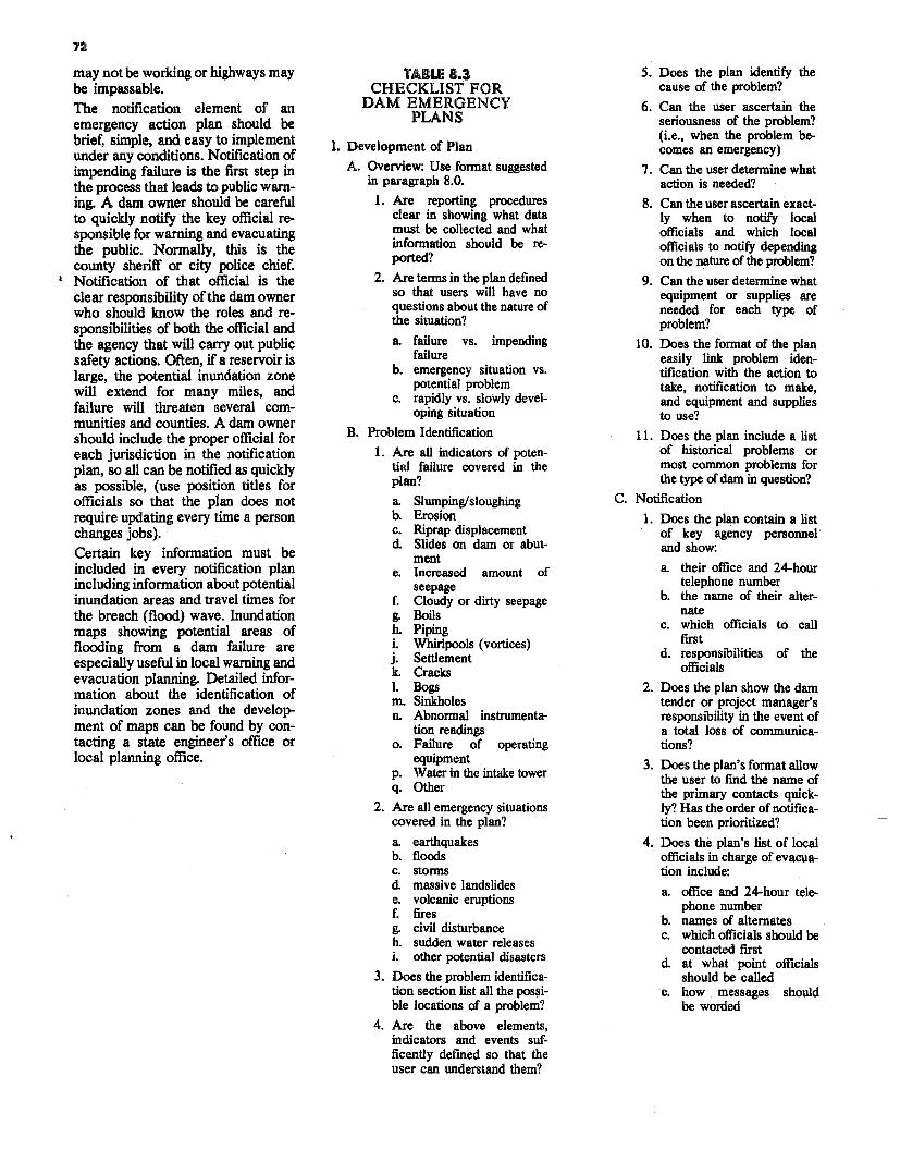
72
may not be working or highways may be impassable. The notification element of an emergency action plan should be brief, simple, and easy to implement under any conditions. Notification of impending failure is the first step in the process that leads to public warning. A dam owner should be careful to quickly notify the key official responsible for warning and evacuating the public. Normally, this is the county sheriff or city police chief.
t Notification of that official is the clear responsibility of the dam owner who should know the roles and responsibilities of both the official and the agency that will carry out public safety actions. Often, if a reservoir is large, the potential inundation zone will extend for many miles, and failure will threaten several communities and counties. A dam owner should include the proper official for each jurisdiction in the notification plan, so all can be notified as quickly as possible, (use position titles for officials so that the plan does not require updating every time a person changes jobs). Certain key information must be included in every notification plan including information about potential inundation areas and travel times for the breach (flood) wave. Inundation maps showing potential areas of flooding from a dam failure are especially useful in local warning and evacuation planning. Detailed information about the identification of inundation zones and the development of maps can be found by contacting a state engineer's office or local planning office.
TABLE 8.3 CHECKLIST FOR
DAM EMERGENCY PLANS
I. Development of Plan
A. Ovel'View: Use format suggested in paragraph 8.0.
1. Are reporting procedures clear in showing what data must be collected and what information should be reported?
2. Are terms in the plan defined so that users will have no questions about the nature of the situation?
a. failure vs. impending failure
b. emergency situation vs. potential problem
c. rapidly vs. slowly developing situation
B. Problem Identification
l. Are all indicators of potential failure covered in the plan?
a. Slumping/sloughing b. Erosion c. Riprap displacement d Slides on dam or abut
ment e. Increased amount of
seepage f. Cloudy or dirty seepage g. Boils h. Piping i. Whirlpools (vortices) j. Settlement k. Cracks l. Bogs m. Sinkholes n. Abnormal instrumenta
tion readings o. Failure of operating
equipment p. Water in the intake tower q. Other
2. Are all emergency situations covered in the plan?
a. earthquakes b. floods c. storms d massive landslides e. volcanic eruptions f. fires g. civil disturbance h. sudden water releases i. other potential disasters
3. Does the problem identification section list all the pos~ible locations of a problem?
4. Are the above elements, indicators and events sufficently defined so that the user can understand them?
5. Does the plan identify the cause of the problem?
6. Can the user ascertain the seriousness of the problem? (i.e., when the problem becomes an emergency)
7. Can the user determine what action is needed?
8. Can the user ascertain exactly when to notify local officials and which local officials to notify depending on the nature of the problem?
9. Can the user determine what equipment or supplies are needed for each type of problem?
10. Does the format of the plan easily link problem identification with the action to take, notification to make, and equipment and supplies to use?
11. Does the plan include a list of historical problems or most common problems for the type ofdam in question?
C. Notification
1. Does the plan contain a list of key agency personnel· and show:
a. their office and 24-hour telephone number
b. the name of their alternate
c. which officials to call first
d. responsibilities of the officials
2. Does the plan show the dam tender or project manager's responsibility in the event of a total loss of communications?
3. Does the plan's format allow the user to find the name of the primary contacts quickly? Has the order ofnotification been prioritized?
4. Does the plan's list of local officials in charge of evacuation include:
a. office and 24-hour telephone number
b. names of alternates c. which officials should be
contacted first d at what point officials
should be called e. how messages should
be worded
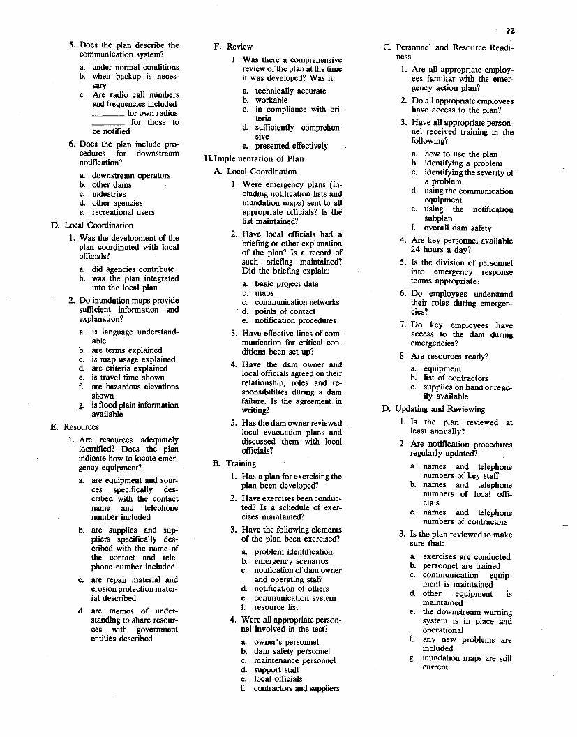
73
5. Does the plan describe the communication system?
a. under normal conditions b. when backup is neces
sary c. Are radio call numbers
and frequencies included ____ for own radios
for those to be notified
6. Does the plan include procedures for downstream notification?
a downstream operators b. other dams c. industries d. other agencies e. recreational users
D. Local Coordination
1. Was the development of the plan coordinated with local officials?
a. did agencies contribute b. was the plan integrated
into the local plan
2. Do inundation maps provide sufficient information and explanation?
a. is language understandable
b. are terms explained c. is map usage explained d. are criteria explained e. is travel time shown f. are hazardous elevations
shown g. is flocx:l plain information
available
E. Resources
1. Are resources adequately identified? Does the plan indicate how to locate emergency equipment?
a. are equipment and sources specifically described with the contact name and telephone number included
b. are supplies and suppliers specifically described with the name of the contact and telephone number included
c. are repair material and erosion protection material described
d. are memos of understanding to share resources with government entities described
F. Review
I. Was there a comprehensive review of the plan at the time it was developed? Was it:
a. technically accurate b. workable c. in compliance with cri
teria d. sufficiently comprehen
sive e. presented effectively
II.Implementation of Plan
A. Local Coordination
1. Were emergency plans (including notification lists and inundation maps) sent to all appropriate officials? Is the list maintained?
2. Have local officials had a briefing or other explanation of the plan? Is a record of such briefing maintained? Did the briefing explain:
a. basic project data b. maps c. communication networlcs d. points of contact e. notification procedures
3. Have effective lines of communication for critical conditions been set up?
4. Have the dam owner and local officials agreed on their relationship, roles and responsibilities during a dam failure. Is the agreement in writing?
5. Has the dam owner reviewed local evacuation plans and discussed them with local officials?
B. Training
1. Has a plan for exercising the plan been developed?
2. Have exercises been conducted? Is a schedule of exercises maintained?
3. Have the following elements of the plan been exercised?
a. problem identification b. emergency scenarios c. notification ofdam owner
and operating staff d. notification of others e. communication system f. resource list
4. Were all appropriate personnel involved in the test?
a. owner's personnel b. dam safety personnel c. maintenance personnel d. support staff e. local officials f. contractors and suppliers
C. Personnel and Resource Readiness
1. Are all appropriate employees familiar with the emergency action plan?
2. Do all appropriate employees have access to the plan?
3. Have all appropriate personnel received training in the following?
a. how to use the plan b. identifying a problem c. identifying the severity of
a problem d. using the communication
equipment e. using the notification
subplan f. overall dam safety
4. Are key personnel available 24 hours a day?
5. Is the division of personnel into emergency response teams appropriate?
6. Do employees understand their roles during emergencies?
7. Do key employees have access to the dam during emergencies?
8. Are resources ready?
a. equipment b. list of contractors c. supplies on hand or read
ily available
D. Updating and Reviewing
1. Is the plan reviewed at least annually?
2. Are· notification procedures regularly updated?
a. names and telephone numbers of key staff
b. names and telephone numbers of local officials
c. names and telephone numbers of contractors
3. Is the plan reviewed to make sure that:
a. exercises are conducted b. personnel are trained c. communication eqwp
ment is maintained d. other equipment is
maintained e. the downstream warning
system is in place and operational
f. any new problems are included
g. inundation maps are still current
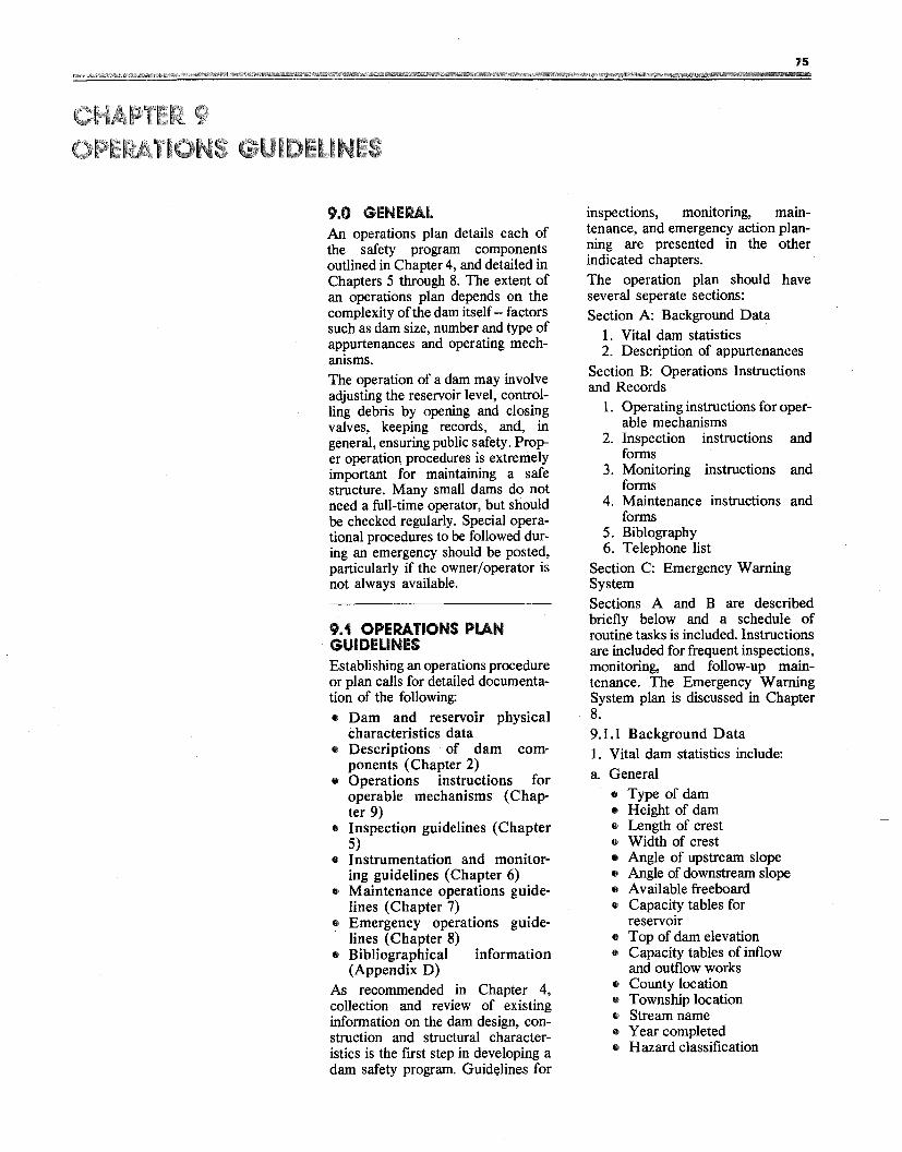
75
9.0 GENERAL An operations plan details each of the safety program components outlined in Chapter 4, and detailed in Chapters 5 through 8. The extent of an operations plan depends on the complexity of the dam itself-- factors such as dam size, number and type of appurtenances and operating mechanisms. The operation of a dam may involve adjusting the reservoir level, controlling debris by opening and closing valves, keeping records, and, in general, ensuring public safety. Proper operation procedures is extremely important for maintaining a safe structure. Many small dams do not need a full-time operator, but should be checked regularly. Special operational procedures to be followed during an emergency should be posted, particularly if the owner/operator is not always available.
9.1 OPERATIONS Pl.AN GUIDELINES Establishing an operations procedure or plan calls for detailed documentation of the following: • Dam and reservoir physical
characteristics data • Descriptions of dam com
ponents (Chapter 2) • Operations instructions for
operable mechanisms (Chapter 9)
• Inspection guidelines (Chapter 5)
• Instrumentation and monitor· ing guidelines (Chapter 6)
• Maintenance operations guide· lines (Chapter 7)
• Emergency operations guidelines (Chapter 8)
• Bibliographical information (Appendix D)
As recommended in Chapter 4, collection and review of existing information on the dam design, construction and structural characteristics is the first step in developing a dam safety program. Guid~lines for
inspections, monitoring, maintenance, and emergency action planning are presented in the other indicated chapters. The operation plan should have several seperate sections: Section A: Background Data
1. Vital dam statistics 2. Description of appurtenances
Section B: Operations Instructions and Records
1. Operating instructions for operable mechanisms
2. Inspection instructions and forms
3. Monitoring instructions and forms
4. Maintenance instructions and forms
5. Biblography 6. Telephone list
Section C: Emergency Warning System Sections A and B are described briefly below and a schedule of routine tasks is included. Instructions are included for frequent inspections, monitoring, and follow-up maintenance. The Emergency Warning System plan is discussed in Chapter 8. 9.1.1 Background Data 1. Vital dam statistics include: a. General
• Type of dam • Height of dam • Length of crest • Width of crest • Angle of upstream slope • Angle of downstream slope • Available freeboard • Capacity tables for
reservoir • Top of dam elevation • Capacity tables of inflow
and outflow works • County location • Township location • Stream name • Year completed • Hazard classification
76
b. Spillway
• Type of spillway • Length of spillway • Spillway channel elevation • Normal pool elevation • Available freeboard • Maximum observed flow
and date of occurrence • Discharge tables for
spillway
c. Outlet
• Size, configuration and type of outlet
• Size and type of outlet control device
• Discharge tables for outlet • Inlet invert elevation • Outlet invert elevation • Drainage systems and
drain locations
9.1.2 Operations Instructions and Records
Operating instructions for operable mechanisms - The plan should provide complete, clear, step-by step instructions for operating all mechanisms associated with a dam including the outlet control valve and spillway gates. Proper sequences should be emphasized and sketches, drawings, and photographs to aid in identifying specific handles, cranks, buttons, etc should be included. The correct method of opening and closing guard gates, gate usage during low and high flow, openings at which excessive vibrations are experienced, and operating problems peculiar to a specific gate should also be listed. For hydraulic and electric gates, a schematic diagram should be provided showing each component (including back-up equipment) and its place in the operating sequence.
Instructions on the general operation of the reservoir, including the regulation of inflow and outlet ditches, should be given. These should state the maximum pool levels to be allowed at different times of the year, maximum and/or minimum carry over storage, maximum and/or minimum permissible outlet releases. They should also describe operation of the outlet to limit or prevent excessive spillway flow, and the method for periodic drainage of the reservoir to permit thorough outlet or upstream slope inspection.
Inspection and instrumentation - A clear, step-by-step set of instructions for conducting a comprehensive
inspection of the dam and its surroundings should also be provided. Forms, for recording data such as those in Appendix A, should be used and copies of all completed inspection records should be kept.
Monitoring instructions - Clear instructions on how to use monitoring instruments and how to take measurements at monitoring points should be prepared, a map identifying each instrument and monitoring point should be included, and forms for recording the data should be provided The monitoring points themselves, plus any seepage or other areas needing special attention should be kept clear ofobscuring growth and be permanently marked, so they can be found during inspection. The help of a qualified engineer will be useful in developing this section.
Monitoring can only be beneficial if the observations are recorded in an orderly way and form a clear performance record. Thus, plotting or charting some of the readings will be necessary. Instructions on how to make and record each measurement or observation must be provided. If the owner's engineer is not going to plot or chart the data, instructions and forms should be developed to allow owners, operators, or maintenance personnel to do this work. An experienced consulting engineer may be helpful in preparing the needed formats.
Maintenance instructions - Instructions for performing periodic maintenance should be given in detail, so that new personnel can understand the task and experienced personnel can verify that they have completed the work properly. All needed maintenance work should be identified and listed This list includes the tasks described in Chapter 7 such as:
I. Removing brush and trees 2. Removing debris 3. Regrading the crest and/or access
roads 4. Removing harmful rodents 5. Operating and lubricating gates 6. Adding riprap when needed 7. Sealing joints in concrete facings 8. aeaning drainpipes and outlets 9. Maintaining monitoring points
10. Maintaining security of operating equipment
Bibliography- All available reference material should be cataloged in a single list. Other title, author or agency responsible for publicatiOn, date and place of publication or brief description, and the permanent location of the material (for example filing cabinet in basement) should be included Even materials without titles or authors, such as photographs and maintenance information, should be listed.
Telephone List - A comprehensive up-to-date listing of important telephone numbers should be maintained and include:
• The owner/operator (home and office) phones
• Employees actively involved with the dam
• The local emergency management agency
• State police • The local police and fire depart
ments • The state agency responsible for
dam safety • Qualified local engineering con
sultants • Downstream residents
9.2 SCHEDULE OF ROUTINE TASKS A schedule should be established that includes both day-to day tasks and tasks performed less frequently during the year. Such a schedule serves to formalize inspection and maintenance procedures and makes it easy to determine when a task should be done. As suggested in Table 9.1, The frequency of a required task is often dependent upon the hazard classification of the dam (See Chapter 3).
9.3 RECORD KEEPING As already suggested, operating a dam should include keeping accurate records of:
1. Observations: All observations should be recorded. Periodic observation of seepage is particularly important. Again, photographs are valuable for recording observations and documenting changes.
2. Maintenance: Written records of maintenance and major repairs are important for evaluating the safety of a dam.
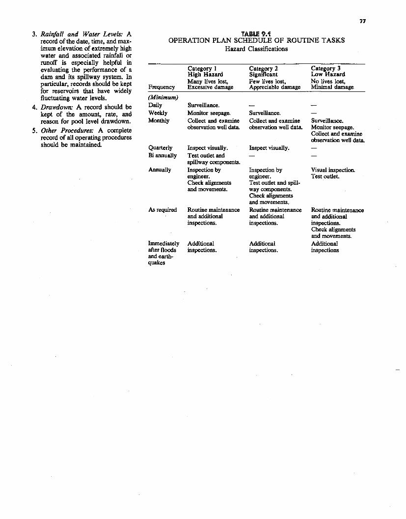
77
3. Rainfall and Water Levels: A TABLE 9.1 record of the date, time, and max OPERATION PLAN SCHEDULE OF ROUTINE TASKS imum elevation of extremely high water and associated rainfall or runoff is especially helpful in evaluating the performance of a dam and its spillway system. In particular, records should be kept for reservoirs that have widely fluctuating water levels.
4. Drawdown: A record should be kept of the amount, rate, and reason for pool level drawdown.
5. Other Procedures: A complete record of all operating procedures should be maintained
Hazard Classifications
Category I Cate~ory 2 Category 3 High Hazard Significant Low Hazard Many lives lost, Few lives lost, No lives lost,
Frequency Excessive damage Appreciable damage Minimal damage
(Minimum) Daily Weekly Monthly
Quarterly Bi annually
Annually
As required
Immediately after floods and earthquakes
Surveillance. Monitor seepage. Surveillance. Collect and examine Collect and examine Surveillance. observation well data. observation well data. Monitor seepage.
Collect and examine observation well data.
Inspect visually. Inspect visually. Test outlet and spillway components. Inspection by Inspection by Visual inspection. engineer. engineer. Test outlet Check alignments Test outlet and spill-and movements. way components.
Check alignments and movements.
Routine maintenance Routine maintenance Routine maintenance and additional and additional and additional inspections. inspections. inspections.
Check alignments and movements.
Additional Additional Additional inspections. inspections. inspections
79
1
10.0 SUPPLEMENTS TO A DAM SAFETY PROGRAM This manual has stressed safety as both a fundamental need and a prime responsibility of the dam owner. Developing an effective dam safety program is the single most important measure a dam owner can take to reduce the possibility or consequences of dam failure. However, on a national scale, an acceptable level of dam safety is still far from being achieved. Losses are continuing to increase and may intensify as poJ>ulation growth and migration continue. From both the perspective of the nation and the dam owner, other steps must be taken to reduce loss of life and property and subsequent liability. Liabilities which are determined following a dam failure strongly affect both organizations and people, governments and dam owners. Determination of liability is the legal means developed by society to recover damages due to a "wrong" (in this case, lack of dam safety) and is another aspect of the dam safety problem. A thorough understanding of this legal process can help the dam owner decide the steps to be taken to reduce liability. A discussion of liability and its relation to a dam owner is presented below, followed by a discussion of three important measures beyond that of individual dam safety that dam owners can promote to reduce liability -- the use of insurance, the provision of governmental assistance, and the use of consultants.
10.1 LIABILITY The following discussion reviews general principles concerning liability and the operation of reservoirs. Liability in specific instances, however, very much depends upon the dam, the accident, the owner and the jurisdiction in which the reservoir is located. The liability of an owner of a reservoir is considered general civil
("tort") liability, A tort is simply a civil wrong for which an injured party may recover damages from the responsible party. In most circumstances, simply causing damage is not sufficient basis for the imposition of liability. Negligence must accompany the injury before liability is incurred However, negligence is not a fixed concept; it has been modified and changed by court decisions over the years. In simplest terms, it has been described as the violation of a duty to act as a reasonable and prudent person would act; a violation which directly results in damage to another. ·
The questions of what "duty" is imposed by society and what standard of reasonable care is imposed by the duty have undergone enormous scrutiny and changes over the past 25 years. In many instances the duty to make a product safe or the duty to insure that one's property does not pose a danger to others, has been significantly increased. While the concept of negligence has been substantially broadened, changes in the limits of negligence do not directly affect dam owners because a separate basis of liability has long been imposed upon them. This standard is one of"strict liability." Strict liability is not based upon fault or negligence, rather it is based solely upon resulting damage, regardless of fault. Strict liability is generally applied to those activities which are deemed "ultra-hazardous" and not capable ofbeing rendered reasonably safe. The whole concept of strict liability was first established in a case involving a reservoir -- the 1866 English case, Fletcher vs. Rylands, L.R 1, Ex. 265. A reservoir was built in the vicinity of abandoned coal mines; the water from the reservoir found its way into the abandoned shafts and from there into active shafts and caused damage. Under present legal thought, the basis of liability for such an occurrence may well be negligent design (i.e., failure to adequately
80
investigate the surrounding circumstances at the time the reservoir was built). However, in the actual decision, it was assumed that no one could have known the abandoned mine shafts existed and specifically decided that the owner was not negligent. Nonetheless, the English Court established the concept of strict liability for reservoir owners, and the owner of the reservoir was found to be liable for the escape of water from the reservoir regardless of fault. Fletcher vs. Rylands has subsequently been adopted by most U.S. courts and has been cited when similar circumstances are considered. It is the basis for imposing liability on the owner of a reservoir for all damages caused, regardless of fault and without need to prove negligence. Thus, with a very limited number of exceptions, the general statement of liability for the owner or operator of a reservoir is:
"IF WATER ESCAPES FROM A DAM, REGARDLESS OF FAULT, THE OWNER IS RESPONSIBLE FOR ALL DAMAGES SUSTAINED."
It should be noted however, that all of the discussion concerriirig compensation for damages due to release of water from a reservoir deal solely with water that has previously been stored. In all circumstances to date, and in most states by specific statute, a reservoir owner may pass on all natural flood waters without incurring any liability downstream. Strict liability has two relatively narrow exceptions: acts of God, or intentional acts of third parties, over whom the owner had no control. While acts of God are recognized as a defense, this does not include all natural occurrences over which the owner had no control, but is more narrowly limited to those events over which the owner had no control and also which the owner could not, using available expertise, have anticipated. The other exception -- intentional acts of third parties - was established by the Wyoming Supreme Court in the Wheatland case. The Wheatland Irrigation District asserted that their reservoir had been damaged by saboteurs, and the Wyoming Supreme Court recognized that illegal,
intentional acts by third parties which the owner could not protect against or anticipate were a viable defense to strict liability. Still, where there is no remedial legislation, the circumstances in which a reservoir owner is not liable for all damages caused by the leaking or breaking of his dam are severely limited. While the standard of liability imposed on a reservoir owner affords extremely limited relief, several states have enacted legislation which limits, in certain circumstances liability for damages. In many other states, by statute or common law, the owner of a reservoir is entitled to utilize (i.e., release water to) the "normal high water line" of a stream without incurring liability for property damaged within the "normal" flood area. However, the definition of the limits within which no liability is imposed vary from place to place and may not be clearly designated on maps. Nonetheless, the right to util
ize defined or "historic" floodplain regions downstream of a reservoir can provide substantial relief from strict liability for a reservoir owner. With the recent insurance crisis and soaring liabililty insurance rates, many states are considering legislation which would limit either the basis of liability or the amount of liability that can be imposed on a reservoir owner. Some states, for example, are considering legislation which would change the standard of liability for a reservoir owner from a standard of "strict liability" to one of proven negligence. If coupled with a redefinition of negligent actions, statutory modification of the basis of a reservoir owner's liability could have a significant effect. However, as noted above, the trend during the past 25 years has been to broaden, not narrow, the scope of negligent behavior by imposing broad expectations of prudence and foresight. Even if standards of "strict liability" are replaced by standards of "negligence," in the case of a reservoir owner, because the criteria of reason
able care and foresight are broadly interpreted, the change may not greatly affect the actual standard of liability imposed. In summary, existing law holds a reservoir owner to the highest standard of care. Pending legislation may limit liability in certain circumstances, however the general statement remains unchanged: the owner is liable for all damages caused by water escaping from a reservoir -- despite the best efforts of the owner.
10.2 MEASURES TO REDUCE THE CONSEQUENCES OF DAM FAILURE A dam owner can directly and indirectly influence the introduction and use of a variety of measures that will reduce the consequences of dam failure. Insurance can be purchased thus, spreading costs from a single dam owner to others. Land use measures, although difficult to institute, can be an even better means of mitigating future disasters. (If people are restricted from living in inundation zones, safety is obviously radically improved.) Increasing public awareness and governmental planning are also measures that can reduce the consequences of dam failure. A dam owner can obtain insurance directly and should do so. The other measures discussed here: land use, public awareness and preparedness planning, are essentially controlled by local governments. Therefore, dam owners would be wise to to encourage as strongly as possible awareness and action in the public sector. Finally, a dam owner may also wish to hire consultants from the private sector when the information needed for prudent decisions exceeds their expertise.
10.2.1 Insurance - Insurance can provide liability and asset protection and thus, is important for dam owners. In many states a minimum level of insurance coverage is mandated by law; in others it is not. In either case, the level of insurance carried should be based on: state law, value of facilities at risk, potential downstream impacts, condition and age of the dam, likelihood of an incident occurring and the cost of available of insurance. Insurance spreads risk among a large group of people and can not only provide protection for the person or organization owning the dam, but also for employees and
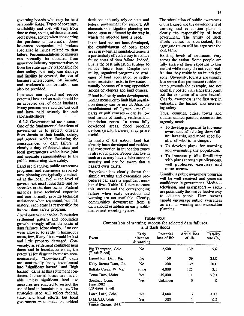
81
governing boards who may be held personally liable. Types of coverage, availability and cost will vary from time to time, so it is, advisable to seek professional advice when considering the purchase of insurance. Some insurance companies and brokers specialize in issues related to dam failure. Recommendations of insurers can normally be obtained from insurance industry representatives or from the state agency responsible for dam safety. Not only can damage and liability be covered, the cost of business interruption, lost income, and workmen's compensation can also be provided. Insurance can spread and reduce potential loss and as such should be an accepted cost of doing business. Many persons have avoided this cost and have paid severely for their shortsightedness. I 0.2.2 Governmental assistance One of the fundamential functions of government is to protect citizens from threats to their health, safety, and general welfare. Reducing the consequences of dam failure is clearly a duty of federal, state and local governments which have joint and separate responsibilities to the public concerning dam safety. Land use planning, public awareness programs, and emergency preparedness planning are typically conducted at the local level -- the level of government most immediate and responsive to the dam owner. Federal agencies have technical expertise and can normally provide technical assistance when requested, but ultimately, each state is responsible for its own dam safety program. Local government roles - Population settlement pattern and population growth strongly affect the costs of dam failures. More simply, if no one were allowed to settle in hazardous areas, few, if any, lives would be lost and little property damaged. Conversely, as settlement continues near dams and in inundation zones, the potential for disaster increases commensurately. "Low-hazard" dams are continually being transformed into "significant hazard" and "high hazard" dams as this settlement continues. Increased losses are inevitable unless significant land use measures are enacted to restrict the use of land in inundation zones. The strategies used will reflect federal, state, and local efforts, but local government must make the critical
decisions and only rely on state and federal government for support. All elements of mitigation planning are based upon or affected by the way in which the affected land is used. If the land has not been developed, the establishment of open space areas in potential inundation zones is a particularly effective way to reduce future costs of dam failure. Indeed, this is the best mitigation strategy to reduce future loss. Despite this utility, organized programs or strategies of land acquisition or settlement restriction exist in few states usually because of strong opposition among developers and land owners. If land is already under development, zoning measures to limit high popula-' tion density can be useful. Also, the establishment of "green areas" parks or golf courses -- can be low cost means of limiting settlement in inundation zones. In some fully developed areas, flood proofing devices (walls, barriers) may prove useful. In much of the nation, land has already been developed and residential construction in inundation zones is already in place. People that live in such areas may have a false sense of security and not be aware that a hazard even exists. Experience has clearly shown that simple warning and evacuation procedures can save a significant number oflives. Table 10.1 demonstrates this success and the corresponding failure when early detection and warning are not available. Clearly, communities downstream from a dam should establish an early notification and warning system.
The stimulation of public awareness of this hazard and the development of warning and evacuation plans is clearly the responsibility of local government. The utility of such efforts cannot be overlooked; the aggregate return will be large over the long term. Existing levels of awareness vary across the nation. Some people are fully aware of their exposure to this hazard while many do not even realize that they reside in an inundation zone. Obviously, tourists are usually less aware than permanent residents; camp grounds for example, are not normally posted with signs that point out the existence of a dam hazard. Clearly, awareness is the first step in mitigating the hazard and increasing safety. Thus, counties, cities, towns and smaller unincorporated communities urgently need: • To develop programs to increase
awareness of existing dam failure hazards, and more specifically, of who is in danger,
• To develop plans for warning and evacuating the population,
• To increase public familiarity with plans through publications, well publicized exercises and other means.
Usually, a public awareness program will be well received and generate confidence in government. Media -television, and newspapers - radio are potentially the most effective way to educate people. Dam owners should encourage public awareness as well as warning and evacuation planning.
Table 10.1 Comparison of warning success for selected dam failures
and flash floods
Early Potential Actual loss Fatality Event direction loss of life of life rate(%)
& warning
Big Thompson, Colo. No 2,500 139 5.6 (Flash Flood) Laurel Run Dam, Pa. No 150 39 25.0 Kelly Barnes Dam, Ga. No 200 39 20.0
Buffalo Creek, W. Va. Some 4,000 125 3.1
Teton Dam, Idaho Yes 35,000 11 <O.l Southern Conn. Yes Unknown 0 0 June 1982 (20 dams failed) Lawn Lake, Colo. Yes 4,000 3 <O.l D.M.A.D, Utah Yes 500 0.2 Source: Graham, 1983.
82
State government roles - Most state governments have actively attempted to reduce the possibility of and consequences of dam failure through any of several major programs. While some local public and private organizations may capable of supervising dain safety, the authority and responsibility for such measures rest with state agencies that approve plans and specifications for the design and construction of dams, and conduct of inspections of existing dams. In most states, dam safety is monitored by the department of water resources, state engineer's office, or an equivalent agency in the executive branch of government. These agencies often determine the rules and regulations governing the design, construction, and maintenance of dams. The state office of emergency preparedness is also concerned with dam safety. However, it deals mainly with planning for the protection of people - awareness, warning and evacuation planning. Disaster (including dam failure) response and recovery efforts are part of this program. Federal government roles - The Federal Emergency Management Agency (FEMA) develops and maintains guidelines for dam safety policy, as well as programs for preparedness, emergency response and recovery planning and mitigation planning. FEMA coordinates all federal dam safety programs, and otherwise promotes both federal and nonfederal programs to reduce the hazard posed by unsafe dams. The Federal Energy Regulatory Commission (FERC) supervises the dam safety program mandated by the Federal Power Act. It issues rules and regulations to ensure that licensed projects are adequately constructec;l, operated and maintained to protect life, health and property. FERC's jurisdiction includes dams at hydroelectric projects on navigable streams or on federally owned land projects using surplus water or waterpower from federally owned dams; and dams affecting interstate or foreign commerce.
The Department of the Army, Corps of Engineers, is authorized by the Federal Water Pollution Control Act of 1972 and the River and Harbor Act of 1899 to issue permits for work involving the nation's waterways. Under the National Dam Safety Act of 1972, the Corps, working with individual states, inventoried 68,153 dams, inspected 8,818, and established a list of hazard criteria. Five agencies within the Department of Agriculture are involved with nonfederal dams. These include the Agricultural Stabilization and Conservation Service (ASCS), the Farmer's Home Administration (FMHA), the Forest Service, the Rural Electrification Administration (REA) and the Soil Conservation Service (SCS). Technical engineering is the responsibility of the Soil Conservation Service. The U.S. Department of the Interior, Office of Surface Mining ( OSM) provides support to state regulatory agencies that conduct dam inspection and monitoring as it relates to surface mining. The Department's Bureau of Reclamation also manages a program of water development which includes providing water for irrigation, the hydroelectric power industry, and recreation. 10.2.3 Consultants role in dam safety - A dam is a special kind of structure which is conceptually simple but made of many complicated components. Several engineering skills are needed to design, build, inspect and repair a dam, and it is uncommon that a dam owner has all of these technical skills. Even if the dam owner did have these skills, it is unlikely that an owner could devote
the time and effort necessary to do the work properly. Thus, private consultants can play an important role in a dam safety program, and owners should consider contracting with consulting firms for assistance. When hiring a consultant, certain steps will insure that an owner obtains what is really needed. The initial screening of possible consultants should be based on professional qualifications. A list of consultants who have experience with dams may be available from the · state office managing dam safety. The owner should then investigate the background and experience ofthe company and the specific experience of the individuals who will do the work. The owner should be sure to define as clearly as possible the work to be done. Although some owners select a consulting firm based on qualifications and then work with the firm to define the work to be done, an owner can often define the scope of work himself, and then receive bids and proposals from several consultants. This latter arrangement usually results in the lowest cost for a given piece of work. Ifmany of the items discussed in this guidebook are new and unfamiliar to a dam owner, a consultant should be contacted immediately. Professional consultants help conduct a proper and safe evaluation of a dam, and can help develop and execute an effective dam safety program. Of course, a dam owner should have confidence in the consultant he hires. When a consultant makes recommendations, they must be taken seriously.
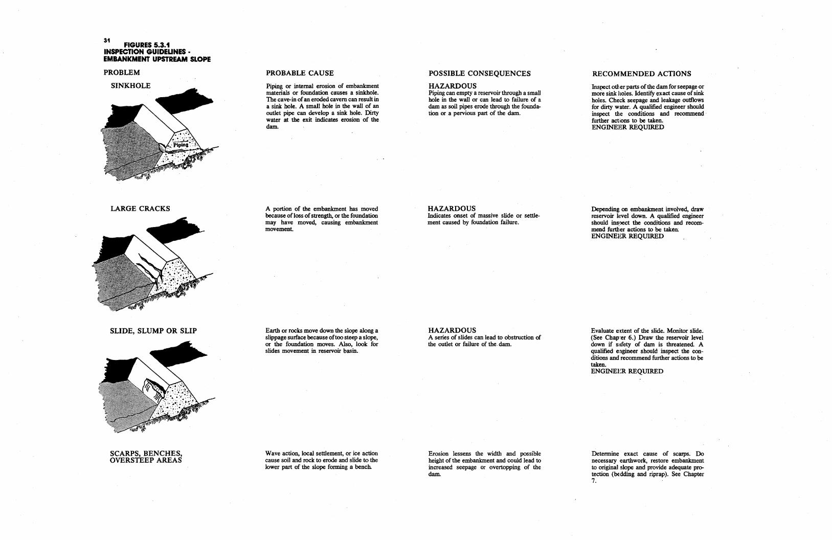
31 FIGURES 5.3.1
INSPECTION GUIDELINES • EMBANKMENT UPSTREAM SLOPE
PROBLEM
SINKHOLE
LARGE CRACKS
SLIDE, SLUMP OR SLIP
SCARPS, BENCHES, OVERSTEEP AREAS
PROBABLE CAUSE
Piping or internal erosion of embankment materials or foundation causes a sinkhole. The cave-in ofan eroded cavern can result in a sink hole. A small hole in the wall of an outlet pipe can develop a sink hole. Dirty water at the exit indicates erosion of the dam.
A portion of the embankment has moved because ofloss ofstrength, or the foundation may have moved, causing embankment movement.
Earth or rocks move down the slope along a slippage surface because oftoo steep a slope, or the foundation moves. Also, look for slides movement in reservoir basin.
Wave action, local settlement, or ice action cause soil and rock to erode and slide to the lower part of the slope forming a bench.
POSSIBLE CONSEQUENCES
HAZARDOUS Piping can empty a reservoir through a small hole in the wall or can lead to failure of a dam as soil pipes erode through the foundation or a pervious part of the dam.
HAZARDOUS fudicates onset of massive slide or settlement caused by foundation failure.
HAZARDOUS A series of slides can lead to obstruction of the outlet or failure of the dam.
Erosion lessens the width and possible height of the embankment and could lead to increased seepage or overtopping of the dam.
RECOMMENDED ACTIONS
fuspect otter parts of the dam for seepage or more sink holes. Identify exact cause of sink holes. Check seepage and leakage outflows for dirty water. A qualified engineer should inspect the conditions and recommend · further actions to be taken. ENGINEER REQUIRED
Depending on embankment involved, draw reservoir fovel down. A qualified engineer should inSr>ect the conditions and recommend furtlier actions to be taken ENGINEER REQUIRED
Evaluate extent of the slide. Monitor slide. (See Chap:er 6.) Draw the reservoir level down if safety of dam is threatened. A qualified engineer should inspect the conditions and recommend further actions to be taken. ENGINEl~R REQUIRED
Determine exact cause of scaips. Do necessary earthwork, restore embankment to original slope and provide adequate pr~ tection (bedding and riprap). See Chapter 7.
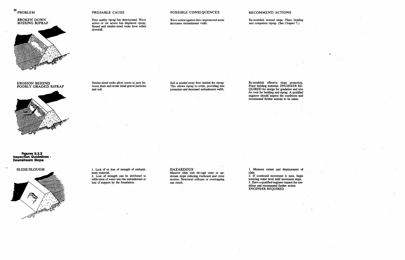
32 PROBLEM
BROKEN DOWN MISSING RIPRAP
EROSION BEHIND POORLY GRADED RIPRAP
Figures 5.3.2 lnspectlon Guidelines • Downstream Slope
SLIDE/SLOUGH
PROBABLE CAUSE
Poor quality riprap has deteriorated Wave action or ice action has displaced riprap. Round and similar-sized rocks have rolled downhill.
Similar-sized rocks allow waves to pass between them and erode small gravel particles and soil.
1. Lack of or loss of strength of embankment material. 2. Loss of strength can be attributed to infiltration of water into the embankment or loss of support by the foundation.
POSSIBLE CONSEQUENCES
Wave action against thes"~ unprotected areas decreases embankment width.
Soil is eroded away from behind the riprap. 1bis allows riprap to settle, providing less protection and decreased embankment width. .
HAZARDOUS Massive slide cuts through crest or upstream slope reducing freeboard and cross section. Structural collapse or overtopping can result.
RECOMMEND ACTIONS
Re-establish normal slope. Place bedding and competent riprap. (See Chapter 7.)
Re-establish effective slope protection. Place bedding material. ENGINEER REQUIRED for design for gradation and size for rock for bedding and riprap. A qualified engineer should inspect the conditions and recommend further actions to be taken.
1. Measure extent and displacement of slide. 2. H continued movement iS seen, begin lowering water level until movement stops. 3. Have a qualified engineer inspect the condition and recommend further action. ENGINEER REQUIRED
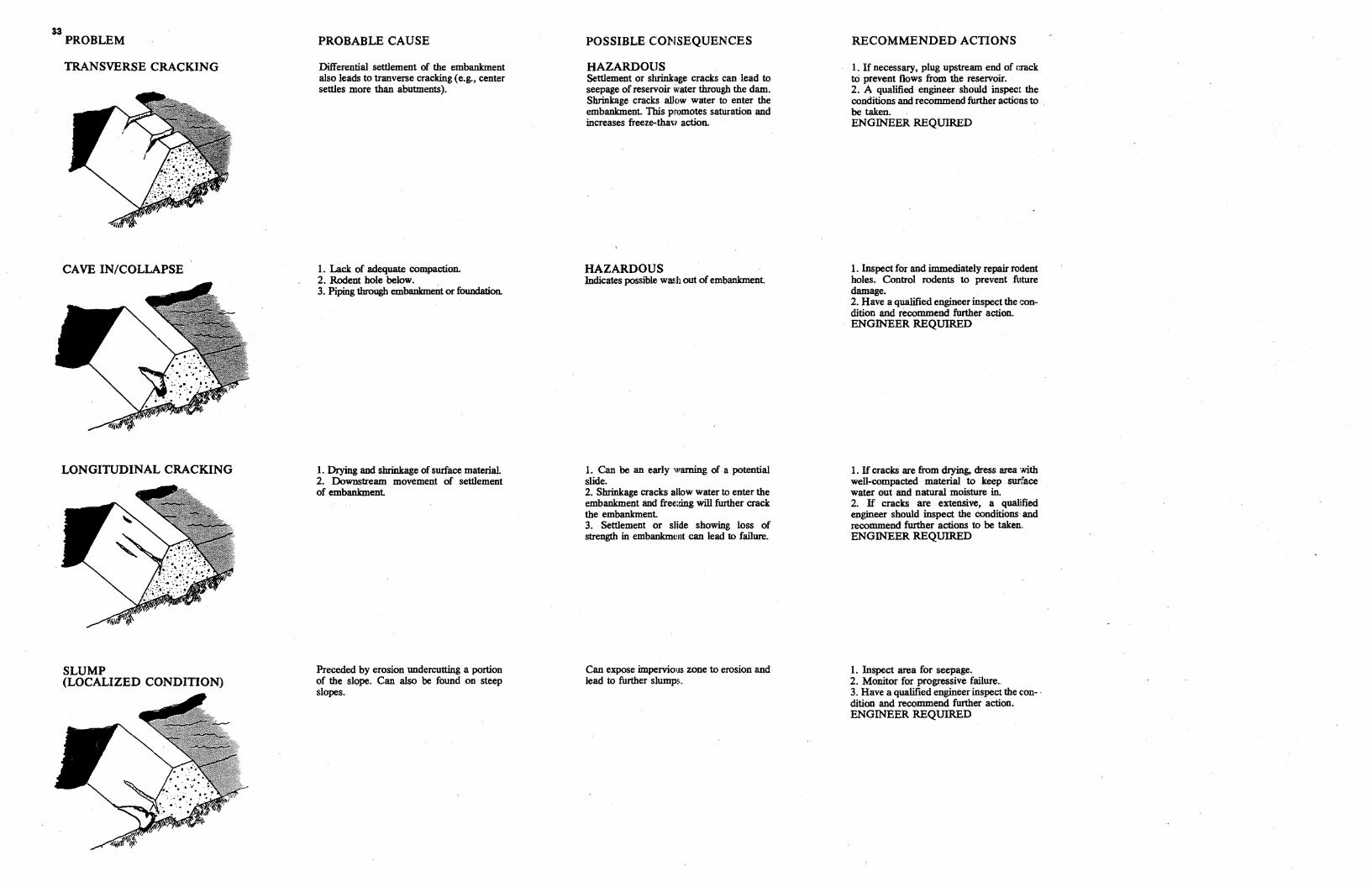
33 PROBLEM
TRANSVERSE CRACKING
CAVE IN/COLLAPSE
LONGITUDINAL CRACKING
SLUMP (LOCALIZED CONDITION)
PROBABLE CAUSE
Differential settlement of the embankment also leads to tranverse cracking (e.g., center settles more than abutments).
1. Lack of adequate compaction. 2. Rodent hole below. 3. Piping through embankment or foundation.
1. Drying and shrinkage of surface material. 2. Downstream movement of settlement of embankment
Preceded by erosion undercutting a portion of the slope. Can also be found on steep slopes.
POSSIBLE CO:t-ISEQUENCES
HAZARDOUS Settlement or shrinkage cracks can lead to seepage of reservoir water through the dam. Shrinkage cracks allow water to enter the embankment. This promotes saturation and increases freeze-thaw action.
HAZARDOUS Indicates possible wash out of embankment
1. Can be an early warning of a potential slide. 2. Shrinkage cracks allow water to enter the embankment and free.;i:ing will further crack the embankment 3. Settlement or slide showing loss of strength in embankmuut can lead to failure.
Can expose impervious zone to erosion and lead to further slumps.
RECOMMENDED ACTIONS
1. H necessary, plug upstream end of c:rack t:O prevent flows from the reservoir. 2. A qualified engineer should inspect the conditions and recommend further actions to be taken. ENGINEER REQUIRED
1. Inspect for and immediately repair rodent holes. Control rodents to prevent future damage. 2. Have a qualified engineer inspect the condition and recommend further action. ENGINEER REQUIRED
1. H cracks are from drying, dress area with well-compacted material to keep swface water out and natural moisture in. 2. If cracks are extensive, a qualified engineer should inspect the conditions· and recommend further actions to be taken. ENGINEER REQUIRED
1. Inspect area for seepage. 2. Monitor for progressive failure .. 3. Have a qualified engineer inspect the con- · dition and recommend further action. ENGINEER REQUIRED
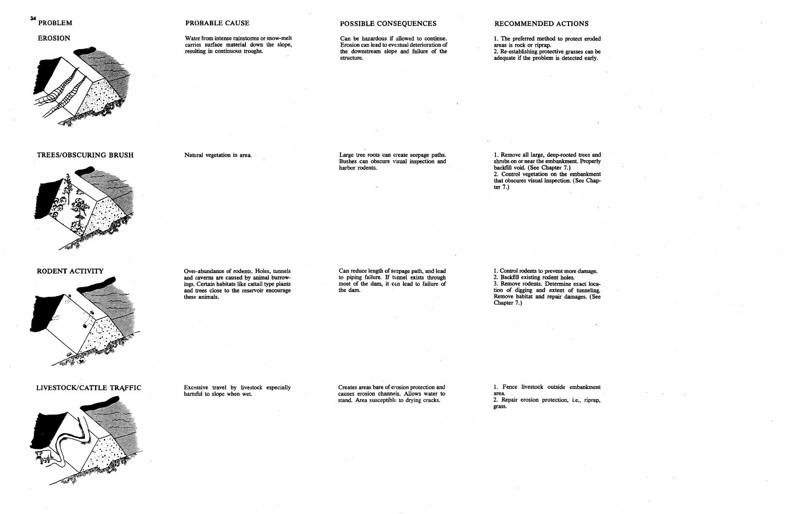
34 PROBLEM PROBABLE CAUSE POSSIBLE CONSEQUENCES RECOMMENDED ACTIONS
EROSION Watf:r from intense rainstorms or snow-melt Can be hazardous if allowed to continue. 1. The preferred method to protect eroded carries surface material down the slope, Erosion can lead to ev1~.atual deterioration of areas is rock or riprap. resulting in continuous troughs. the downstream slope and failure of the 2. Re-establishing protective grasses can be
structure. adequate if the problem is detected early.
TREES/OBSCURING BRUSH
RODENT ACTIVITY
LIVESTOCK/CATTLE TRJ\FFIC
Natural vegetation in area
Ove1~abundance of rodents. Holes, tunnels and caverns are caused by animal burrowings. Certain habitats like cattail type plants and trees close to the reservoir encourage these animals.
Excessive travel by livestock especially hanuful to slope when wet
Large tree roots can create seepage paths. Bushes can obscure visual inspection and harbor rodents.
Can reduce length of se·~page path, and lead to piping failure. H tunnel exists through most of the dam, it cm1 lead to failure of the dam.
Creates areas bare of erosion protection and causes erosion channels. Allows water to stand. Area susceptibl<: to drying cracks.
1. Remove all large, deep-rooted trees and shrubs on or near the embankment. Properly backfill void (See Chapter 7.) 2. Control vegetation on the embankment that obscures visual inspection. (See Chapter 7 .)
1. Control rodents to prevent more damage. 2. Backfill existing rodent holes. 3. Remove rodents. Determine exact location of digging and extent of tunneling. Remove habitat and repair damages. (See Chapter 7.)
l. Fence livestock outside embankment area 2. Repair erosion protection, i.e., riprap, grass.
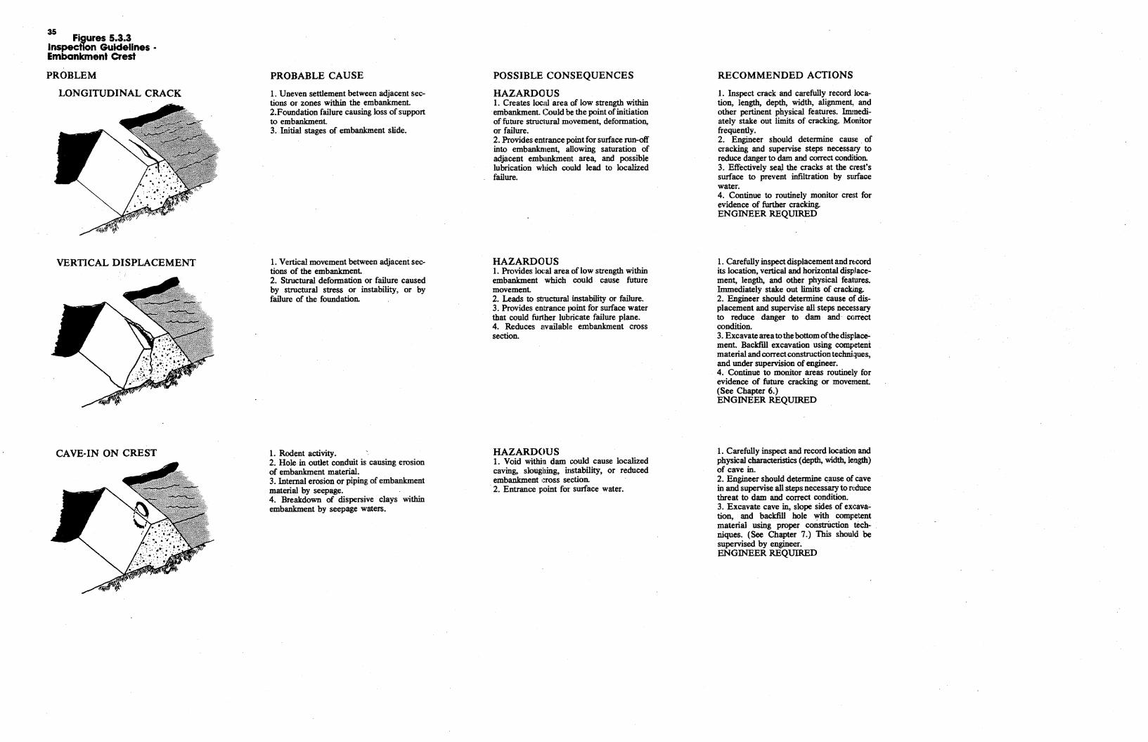
35 Figures 5.3.3
Inspection Guidelines · Embankment Crest
PROBLEM
LONGITUDINAL CRACK
VERTICAL DISPLACEMENT
CAVE-IN ON CREST
PROBABLE CAUSE
1. Uneven settlement between adjacent sections or zones within the embankment. 2.Foundation failure causing loss of support to embankment 3. Initial stages of embankment slide.
1. Vertical movement between adjacent sections of the embankment 2. Structural deformation or failure caused by structural stress or instability, or by failure of the foundation.
1. Rodent activity. 2. Hole in outlet conduit is causing erosion of embankment material. 3. Internal erosion or piping of embankment material by seepage. 4. Breakdown of dispersive clays within embankment by seepage waters.
POSSIBLE CONSEQUENCES
HAZARDOUS 1. Creates local area of low strength within embankment. Could be the point of initiation of future struc1ural movement, deformation. or failure. 2. Provides entrance point for surface run-off into embankment, allowing saturation of adjacent embankment area, and possible lubrication which could lead to localized failure.
HAZARDOUS 1. Provides lcx;al area of low strength within embankment which could cause future movement 2. Leads to structural instability or failure. 3. Provides entrance point for surface water that could funher lubricate failure plane. 4. Reduces i1vailable embankment cross section.
HAZARDOUS 1. Void within dam could cause localized caving, sloughing, instability, or reduced embankment 1:ross section. 2. Entrance point for surface water.
RECOMMENDED ACTIONS
1. Inspect crack and carefully record location, length, depth, width, alignment, and other pertinent physical features. Immediately stake out limits of cracking. Monitor frequently. 2. Engineer should determine cause of cracking and supervise steps necessary to reduce danger to dam and correct condition. 3. Effectively sea) the cracks at the crest's surface to prevent infiltration by surface water. 4. Continue to routinely monitor crest for evidence of further cracking. ENGINEER REQUIRED
1. Carefully inspect displacement and record its location, vertical and horizontal displacement, length, and other physical features. Immediately stake out limits of cracking. 2. Engineer should determine cause of displacement and supervise all steps necessary to reduce danger to dam and· correct condition. 3. Excavate area tothe bottom ofthe displacement. Backfdl excavation using competent material and correct construction techniques, and under supervision of engineer. 4. Continue to monitor areas routinely for evidence of future cracking or movement. (See Chapter 6.) ENGINEER REQUIRED
1. Carefully inspect and record location and physical characteristics (depth, width, length) of cave in. 2. Engineer should determine t:ause of cave in and supervise all steps necessary to rt'<iuce threat to dam and correct condition. 3. Excavate cave in, slope sides of ex1:avation, and backfill hole with competent material using proper constriiction techniques. (See Chapter 7.) This should be supervised by engineer. ENGINEER REQUIRED
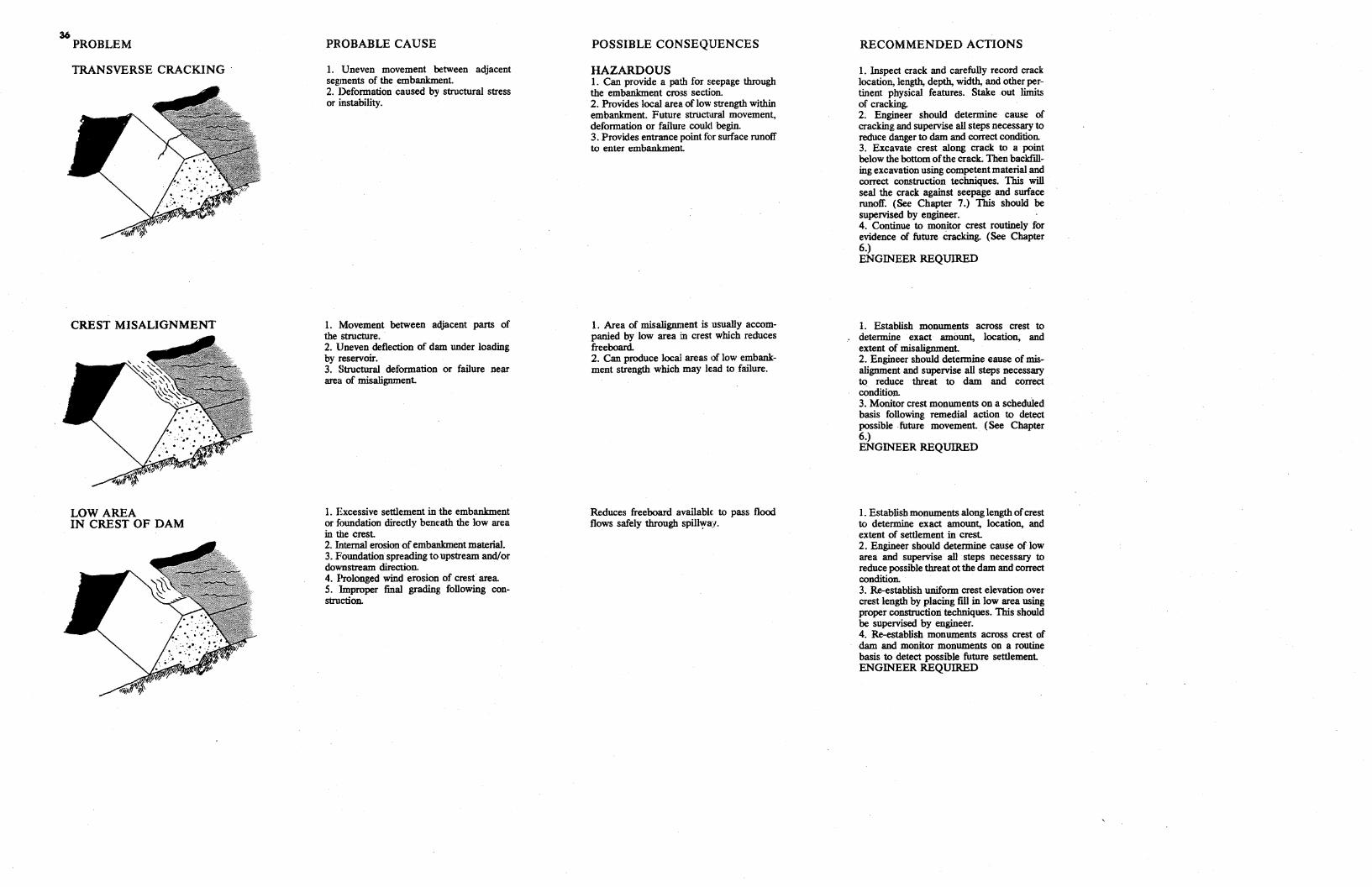
36 PROBLEM
TRANSVERSE CRACKING
CREST MISALIGNMENT
LOW AREA IN CREST OF DAM
PROBABLE CAUSE
1. Uneven movement between adjacent segments of the embankment. 2. Deformation caused by structural stress or instability.
1. Movement between adjacent parts of the structure. 2. Uneven deflection of dam under loading by reservoir. 3. Structural deformation or failure near area of misalignment.
I. Excessive settlement in the embankment or foundation directly beneath the low area in the crest. 2. Internal erosion of embankment material. 3. Foundation spreading to upstream and/or downstream direction. 4. Prolonged wind erosion of crest area 5. Improper final grading following construction.
POSSIBLE CONSEQUENCES
HAZARDOUS 1. Can provide a path for seepage through the embankment cross section. 2. Provides local area of low strength within embankment. Future structural movement, deformation or failure could begin. 3. Provides entrance point for surface runoff to enter embankment
1. Area of misalignment is usually accompanied by low area in crest which reduces free board. 2. Can produce local areas of low embankment strength which may lead to failure.
Reduces freeboard available. to pass flood flows safely through spill~a:f.
RECOMMENDED ACTIONS
1. Inspect crack and carefully record crack location, length, depth, width, and other pertinent physical features. Stake out limits of cracking. 2. Engineer should determine cause of cracking and supervise all steps necessary to reduce danger to dam and correct condition. 3. Excavate crest along crack to a point below the bottom ofthe crack. Then backfilling excavation using competent material and correct construction techniques. This will seal the crack against seepage and surface runoff. (See Chapter 7.) This should be supervised by engineer. 4. Continue to monitor crest routinely for evidence of future cracking. (See Chapter 6.) ENGINEER REQUIRED
1. Establish monuments across crest to determine exact amount, location, and extent of misalignment. 2. Engineer should determine eause of misalignment and supervise all steps necessary to reduce threat to dam and correct condition. 3. Monitor crest monuments on a scheduled basis following remedial action to detect possible . future movement. (See Chapter 6.) ENGINEER REQUIRED
I. Establish monuments along length ofcrest to determine exact amount, location, and extent of settlement in crest. 2. Engineer should determine cause of low area and supervise all steps necessary to reduce possible threat ot the dam and correct condition. 3. Re-establish uniform crest elevation over crest length by placing fill in low area using proper construction techniques. This should be supervised by engineer. 4. Re-establish monuments across crest of dam and monitor monuments on a routine basis to detect possible future settlement. ENGINEER REQUIRED
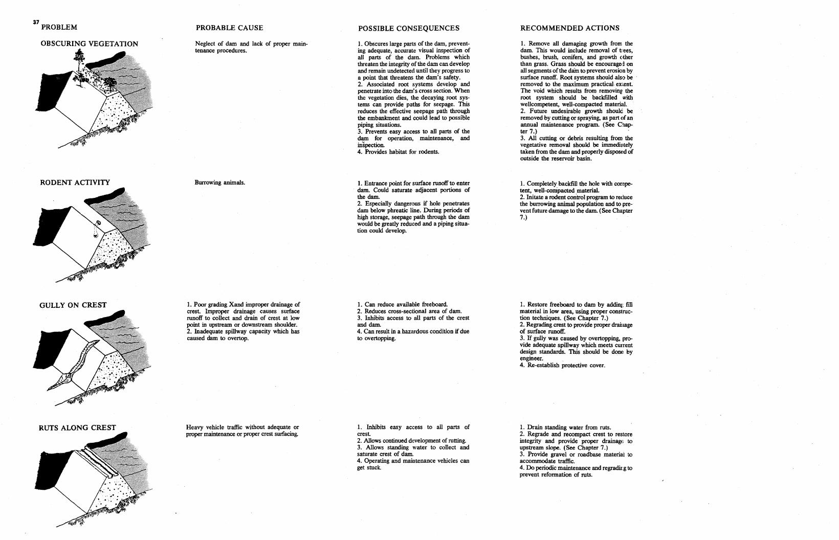
37 PROBLEM
RODENT ACTIVITY
GULLY ON CREST
RUTS ALONG CREST
PROBABLE CAUSE
Neglect of dam and lack of proper maintenance procedures.
Burrowing animals.
1. Poor grading Xand improper drainage of crest. Improper drainage causes surface runoff to collect and drain of crest at low point in upstream or downstream shoulder. 2. Inadequate spillway capacity which has caused dam to overtop.
Heavy vehicle traffic without adequate or proper maintenance or proper crest surfacing.
POSSIBLE CONSEQUENCES
1. Obscures large parts of the dam, preventing adequate, accurate visual inspection of all parts of the darn. Problems which threaten the integrity of the dam can develop and remain undetected until they progress to a point that threatens the dam's safety. 2. Associated root systems develop and penetrate into the dam's cross section. When the vegetation dies, 1he decaying root systems can provide paths for seepage. This reduces the effective seepage path through the embankment and could lead to possible piping situations. 3. Prevents easy access to all parts of the dam for operation, maintenance, and mspection. 4. Provides habitat for rodents.
1. Entrance point for surface runoff to enter dam. Could saturate adjacent portions of the dam. 2. Especially dangerous if hole penetrates dam below phreatic line. During periods of high storage, seepage path through the dam would be greatly reduced and a piping situation could develop.
1. Can reduce available freeboard. 2. Reduces cross-seclfonal area of dam. 3. Inhibits access to all parts of the crest and dam. 4. Can result in a hazardous condition ifdue to overtopping.
1. Inhibits easy access to all parts of crest 2. Allows continued d1~velopment of rutting. 3. Allows standing water to collect and saturate crest of dam. 4. Operating and maintenance vehicles can get stuck.
RECOMMENDED ACTIONS
1. Remove all damaging growth from the dam. This would include removal of t·ees, bushes, brush, conifers, and growth either than grass. Grass should be encouraged on all segments ofthe cUiin to prevent erosion by surface runoff. Root systems should .also be · removed to the maximum practical. exr.ent. The void which results from removin11 the root system should be backfilled with wellcompetent, well-compacted material. 2. Future undesirable growth shouk. be removed by cutting or spraying, as part of an annual maintenance program. (See 01.apter 7.) 3. All cutting or debris resulting from the vegetative removal should be immedi1:1tely taken from the dam and properly disposed of outside the reservoir basin.
1. Completely backfill the hole with competent, well-compacted material. 2. Initate a rodent control program to reduce the burrowing animal population and to .prevent future damage to the dam. (See Chapter 7.)
1. Restore freeboard to dam by addin1: fill material in low area, using proper construction techniques. (See Chapter 7.) 2. Regrading crest to provide proper drainage of surface runoff. 3. H gully was caused by overtopping, prcr vide adequate spillway which meets cwTent design standards. This should be dom: by engineer. 4. Re-establish protective cover.
1. Drain standing water from ruts. 2. Regrade and recompact crest to restore integrity and provide proper drainage to upstream slope. (See Chapter 7.) 3. Provide gravel or roadbase material to accommodate traffic. 4. Do periodic maintenance and regradir.g to prevent reformation of ruts.
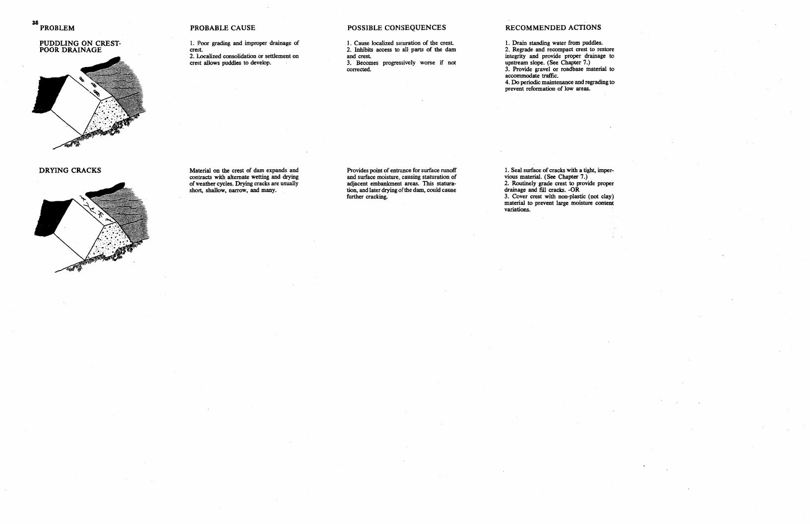
38 PROBLEM
PUDDLING ON CRESTPOOR DRAINAGE
DRYING CRACKS
PROBABLE CAUSE
1. Poor grading and improper drainage of crest. 2. Localized consolidation or settlement on crei;t allows puddles to develop.
Material on the crest of dam expands and contracts with alternate wetting and drying of weather cycles. Drying cracks are usually short, shallow, narrow, and many.
POSSIBLE CONSEQUENCES
1. Cause localized sawration of the crest. 2. Inhibits access to all parts of the dam and crest. 3. Becomes progressively worse if not corrected.
Provides point of entrnnce for surface runoff and surface moisture, causing staturation of adjacent embankment areas. This staturation, and later drying of the dam, could cause further cracking.
RECOMMENDED ACTIONS
1. Drain standing water from puddles. 2. Regrade and recompact crest to restore integrity and provide proper drainage to upstream slope. (See Chapter 7 .) 3. Provide gravel or roadbase material to accommodate traffic. 4. Do periodic maintenance and regrading to prevent reformation of low areas.
1. Seal surface of cracks with a tight, impervious material. (See Chapter 7.) 2. Routinely grade crest to provide proper drainage and fill cracks. -OR 3. Cover crest with non-plastic (not clay) material to prevent large moisture content variations. ·
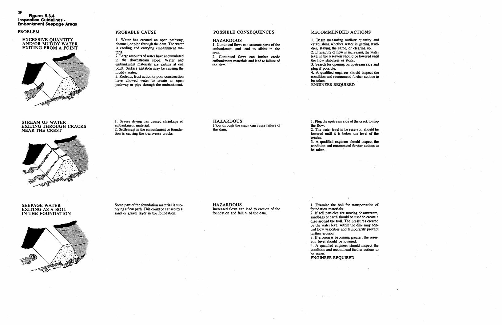
39 Fisures 5.3A
Inspection Guidelines • Embankinent Seepage Areas
PROBLEM
EXCESSIVE QUANTITY AND/OR MUDDY WATER EXITING FROM A POINT
STREAM OF WATER EXITING THROUGH CRACKS NEAR THE CREST
SEEPAGE WATER EXITING AS A BOIL IN THE FOUNDATION
PROBABLE CAUSE
1. Water has created an open pathway, channel, or pipe through the dam. The water is eroding and carrying embankment material. 2. Large amounts ofwater have accumulated in the downstream slope. Water and embankment materials are exiting at one point. Surface agitation may be causing the muddy water. 3. Rodents, frost action or poor construction have allowed water to create an open pathway or pipe through the embankment
1. Severe drying has caused shrinkage of embankment material. 2. Settlement in the embankment or foundation is causing the transverse cracks.
Some part of the foundation material is supplying a flow path. This could be caused by a sand or gravel layer in the foundation.
POSSIBLE CONSEQUENCES
HAZARDOUS 1. Continued flows can saturate parts of the embankment and lead to slides in the area. 2. Continued flows can further erode embankment materials and lead to failure of the dam.
HAZARDOUS Flow through the crack can cause failure of the dam.
HAZARDOUS Increased flows can lead to erosion of the foundation and failun: of the dam.
RECOMMENDED ACTIONS
1. Begin measuring outflow quantity and establishing whether water is getting rr:uddier, staying the same, or clearing up. 2. If quantity of flow is increasing the water level in the reservoir should be lowered until the flow stabilizes or stops. 3. Search for opening on upstream side and plug if possible. 4. A qualified engineer should inspect the condition and recommend further actions to be taken. · ENGINEER REQUIRED
1. Plug the upstream side of the crack to stop the flow. 2. The water level in he reservoir should be lowered until it is below the level of the cracks. 3. A qualified engineer should inspect the condition and recommend further actions to be taken.
1. Examine the boil for transportatio:i; of foundation materials. 2. If soil particles are moving downstream, sandbags or earth should be used to create a dike ·around the boil. The pressures created by the water level within the dike may control flow velocities and temporarily preYent further erosion. 3. If erosion is becoming greater, the reservoir level should be lowered. 4. A qualified engineer should inspect the condition and recommend further actions to be taken. ENGINEER REQUIRED
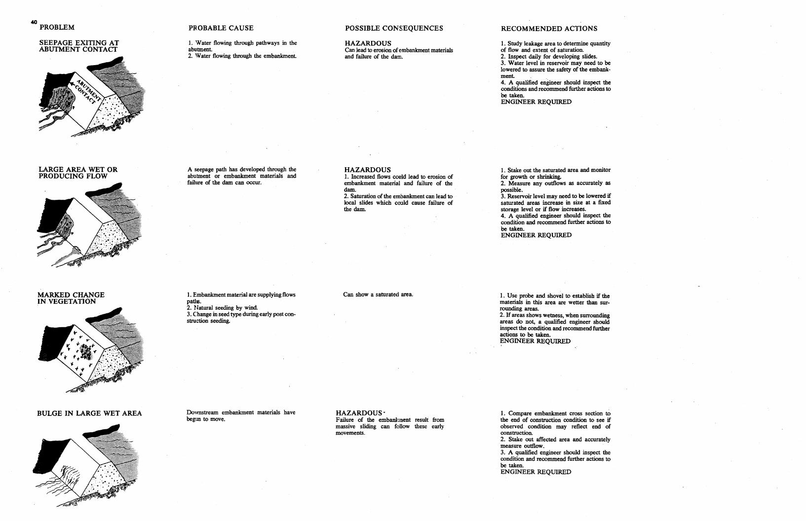
40 PROBLEM
SEEPAGE EXITING AT ABUTMENT CONTACT
LARGE AREA WET OR PRODUCING FLOW
MARKED CHANGE IN. VEGETATION
BULGE IN LARGE WET AREA
PROBABLE CAUSE
1. Water flowing through pathways in the abutment. 2. Water flowing through the embankment.
A seepage path has developed through the abutment or embankment materials and failure of the dam can occur.
I. Embankment material are supplying flows paths. 2. Natural seeding by wind 3. Change in seed type during early post construction seeding.
Downstream embankment materials have begim to move.
POSSIBLE CONSEQUENCES
HAZARDOUS Can lead to erosion ofembankment materials and failure of the dam.
HAZARDOUS 1. Increased flows could lead to erosion of embankment material and failure of the dam. 2. Saturation of the embankment can lead to local slides which could cause failure of the dam.
Can show a saturated area.
HAZARDOUS· Failure of the embankment result from massive sliding can follow these early movements.
RECOMMENDED ACTIONS
1. Study leakage area to determine quantity of flow and extent of saturation. 2. Inspect daily for developing slides. 3. Water level in reservoir may need to be lowered to assure the safety of the embankment. . 4. A qualified engmeer should inspect the conditions and recommend further actions to be taken. ENGINEER REQUIRED
1. Stake out the saturated area and monitor for growth or shrinking. 2. Measure any outflows as accurately as possible. 3. Reservoir level may need to be lowered if saturated areas increase in size at a fixed storage level or if flow increases. 4. A qualified engineer should inspect the condition and recommend further actions to be taken. ENGINEER REQUIRED
1. Use probe and shovel to establish if the materials in this area are wetter than surrounding areas. 2. Ifareas shows wetness, when surrounding areas do not, a qualified engineer should inspect the condition and recommend further actions to be taken. ~NGINEER REQUIRED
l. Compare embankment cross section to the end of construction condition to see if observed condition may reflect end of construction. 2. Stake out affected area and accurately measure outflow. 3. A qualified engineer should inspect the condition and recommend further actions to be taken. ENGINEER REQUIRED
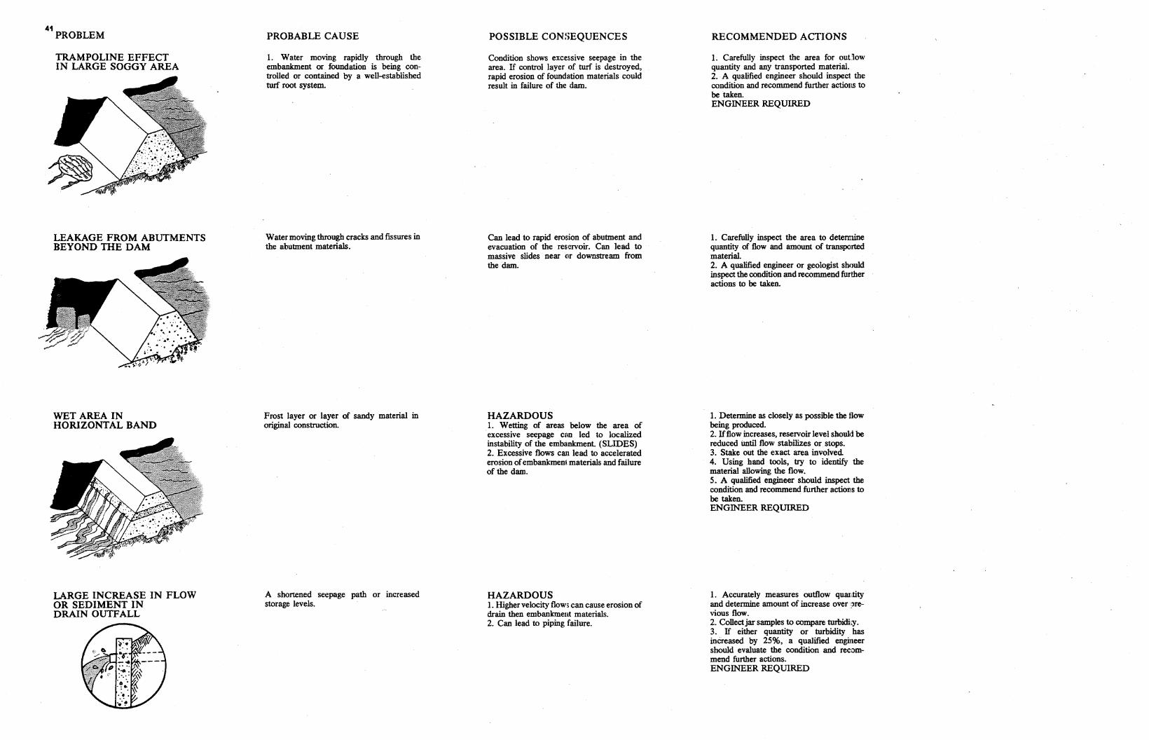
41 PROBLEM
TRAMPOLINE EFFECT IN LARGE SOGGY AREA
LEAKAGE FROM ABUTMENTS BEYOND THE DAM
WET AREA IN HORIZONTAL BAND
LARGE INCREASE IN FLOW OR SEDIMENT IN DRAIN OUTFALL
PROBABLE CAUSE
1. Water moving rapidly through the embankment or foundation is being controlled or contained by a well-established turf root system.
Water moving through cracks and fissures in the abutment materials.
Frost layer or layer of sandy material in original construction.
A shortened seepage path or increased storage levels.
POSSIBLE CON!>EQUENCES
Condition shows excessive seepage in the area. If control layer of turf is destroyed, rapid erosion of foundation materials could result in failure of the dam.
Can lead to rapid erosion of abutment and evacuation of the reservoir. Can lead to massive slides near ur downstream from the dam.
HAZARDOUS 1. Wetting of areas below the area of excessive seepage can led to localized instability of the embankment (SLIDES) 2. Excessive flows can lead to accelerated erosion ofembankment materials and failure of the dam.
HAZARDOUS 1. Higher velocity flows can cause erosion of drain then embankment materials. 2. Can lead to piping failure.
RECOMMENDED ACTIONS
1. Carefully inspect the area for out:low quantity and any transported material. 2. A qualified engineer should inspect the condition and recommend further actions to be taken. ENGINEER REQUIRED
1. Carefully inspect the area to detemline quantity of flow and amount of transported material. 2. A qualified engineer or geologist should inspect the condition and recommend further actions to be taken.
1. Determine as closely as possible the tlow being produced. 2. Ifflow increases, reservoir level should be reduced until flow stabilizes or stops. 3. Stake out the exact area involved 4. Using hand tools, try to identify the material allowing the flow. 5. A qualified engineer should inspect the condition and recommend further actions to be taken. ENGINEER REQUIRED
1. Accurately measures outflow qum:;.tity and determine amount of increase over :~revious flow. 2. Collectjar samples to compare turbidicy. 3. If either quantity or turbidity has increased by 25%, a qualified engineer should evaluate the condition and recommend further actions. ENGINEER REQUIRED
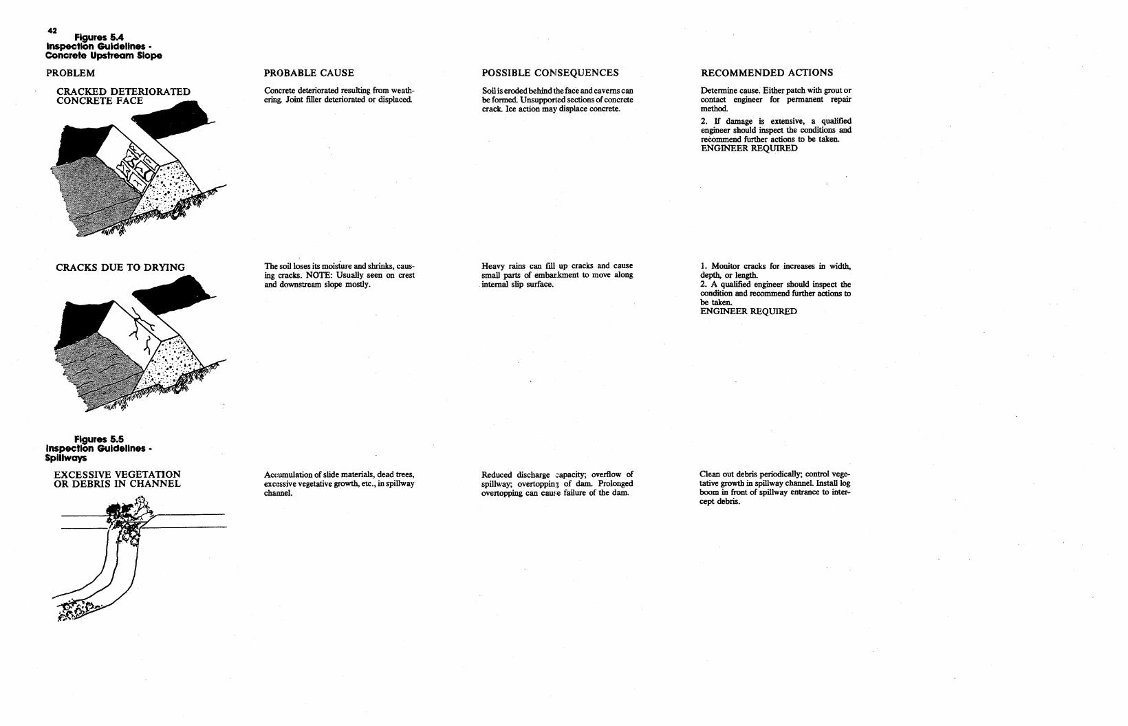
42 Figures SA
Inspection Guidelines • Concrete Upstream Slope
PROBLEM
CRACKED DETERIORATED CONCRETE FACE
CRACKS DUE TO DRYING
Figures 5.5 Inspection Guldellnes • Spillways
EXCESSIVE VEGETATION OR DEBRIS IN CHANNEL
PROBABLE CAUSE
Concrete deteriorated resulting from weathering. Joint filler deteriorated or displaced
The soil loses its moisture and shrinks, causing cracks. NOTE: Usually seen on crest and downstream slope mostly.
Accumulation of slide materials, dead trees, excessive vegetative growth, etc., in spillway channel.
POSSIBLE CONSEQUENCES
Soil is eroded behind the face and caverns can be formed Unsupported sections ofconcrete crack. Ice action may displace concrete.
Heavy rains can fill up cracks and cause small parts of embarkment to move along internal slip surface.
Reduced discharge .:apacity; overflow of spillway; overtoppin.~ of dam. Prolonged overtopping can cam:e failure of the dam.
RECOMMENDED ACTIONS
Determine cause. Either patch with grout or contact engineer for permanent repair method.
2. If damage is extensive, a qualified engineer should inspect the conditions and reeommend further actions to be taken. ENGINEER REQUIRED
1. Monitor cracks for increases in width, depth, or length. 2. A qualified engineer should inspect the condition and recommend further actions to be taken. ENGINEER REQUIRED
Clean out debris periodically; control vegetative growth in spillway channel. Install log boom in front of spillway entrance to intercept debris.
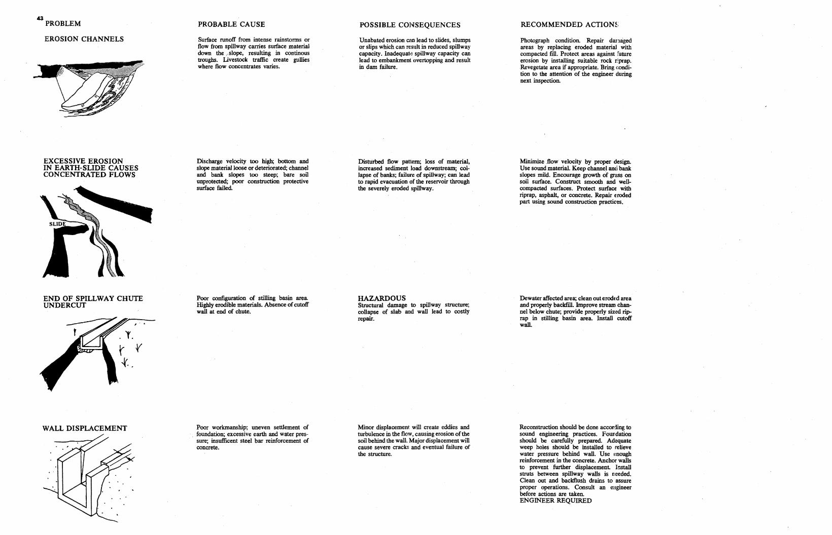
43 PROBLEM
EROSION CHANNELS
EXCESSIVE EROSION IN EARTH-SLIDE CAUSES CONCENTRATED FLOWS
END OF SPILLWAY CHUTE UNDERCUT
WALL DISPLACEMENT
PROBABLE CAUSE
Surface runoff from intense rainstorms or flow from spillway carries surface material down the ,, slope, resulting in continous troughs. Livestock traffic create gullies where flow concentrates varies.
Discharge velocity too high; bottom and slope material loose or deteriorated; channel and bank slopes too steep; bare soil unprotected; poor construction protective surface failed
Poor configuration of stilling basin area Highly erodible materials. Absence of cutoff wall at end of chute.
Poor workmanship; uneven settlement of foundation; excessive earth and water pressure; insufficent steel bar reinforcement of concrete.
POSSIBLE CONSEQUENCES
Unabated erosion can lead to slides, slumps or slips which can result in reduced spillway capacity. Inadequat•! spillway capacity can lead to embankment overtopping and result in dam failure.
Distl.irbed flow pattern; loss of material, increased sediment load downstream; collapse of banks; failure of spillway; can lead to rapid evacuation of the reservoir through the severely eroded spillway.
HAZARDOUS Structural damage to spillway structure; collapse of slab and wall lead to costly repair.
Minor displacement will create eddies and turbulence in the flow, causing erosion ofthe soil behind the wall. Major displacement will cause severe crack!; and eventual failure of the structure.
RECOMMENDED ACTION~.
Photograph condition. Repair danaged areas by replacing eroded material with compacted fill. Protect areas against future erosion by installing suitable rock r'.prap. Revegetate area if appropriate. Bring condition to the attention of the engineer during next inspection. ·
Minimize .flow velocity by proper design. Use sound material. Keep channel and bank slopes mild. Encourage growth of grl!SS on soil surface. Construct smooth and wellcompacted surfaces. Protect surface with riprap, asphalt, or concrete. Repair eroded part using sound construction practices.
Dewater affected area; clean out erodtd area and properly backfill. Improve stream channel below chute; provide properly siz,~d riprap in stilling basin area. Install cutoff wall.
Reconstruction should be done according to sound engineering practices. Folllldation should be carefully prepared Adequate weep boles should be installed to relieve water pressure behind wall. Use enough reinforcement in the concrete. Anchor walls to prevent further displacement Install struts between spillway walls is Deeded. Clean out and backflusb drains to assure proper operations. Consult an ellgineer before actions are taken. ENGINEER REQUIRED
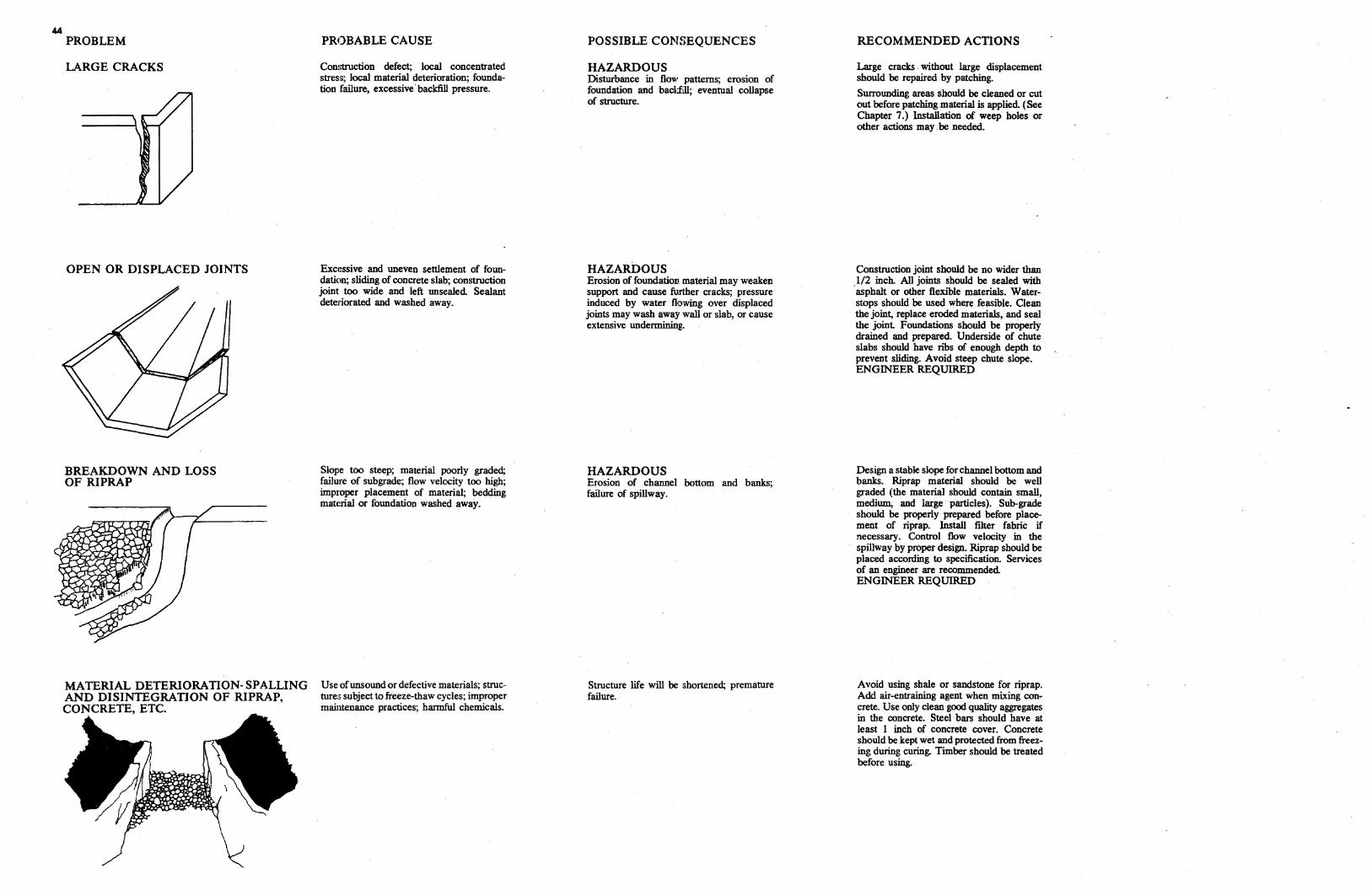
44 PROBLEM
LARGE CRACKS
OPEN OR DISPLACED JOINTS
BREAKDOWN AND LOSS OF RIPRAP
MATERIAL DETERIORATION-SPALLI
NG AND DISINTEGRATION OF RIPRAP,CONCRETE, ETC.
PROBABLE CAUSE
Com;truction defect; local concentrated stress; local material deterioration; foundation failure, excessive· backfill pressure.
Excessive and uneven settlement of foundation; sliding of concrete slab; construction joint too wide and left unsealed Sealant dete1iorated and washed away.
Slope too steep; material poorly graded; failure of subgrade; flow velocity too high; improper placement of material; bedding matc:rial or foundation washed away.
Use ofunsound or defective materials; structure:; subject to freeze-thaw cycles; improper maintenance practices; harmful chemicals.
POSSIBLE CONSEQUENCES
HAZARDOUS Disturbance in flow patterns; erosion of foundation and backfill; eventual collapse of structure.
HAZARDOUS Erosion of foundation. material may weaken support and cause further cracks; pressure induced by water flowing over displaced joints may wash away wall or slab, or cause extensive undermining.
HAZARDOUS Erosion of channel bottom and banks; failure of spillway.
Structure life will be shortened; premature failure.
RECOMMENDED ACTIONS
Large cracks . without large displacement should be repaired by patching.
Surrounding areas should be cleaned or cut out before patching material is applied. (See Chapter 7.) Installation of weep holes or other actions may . be needed.
Construction joint should be no wider than 1/2 inch. All joints should be sealed with ·asphalt or other flexible materials. Waterstops should be used where feasible. Clean the joint, replace eroded materials, and seal the joint Foundations should be properly drained and prepared. Underside of chute slabs should have nbs of enough depth to prevent sliding. Avoid steep chute slope. ENGINEER REQUIRED
Design a stable slope for channel bottom and banks. Riprap material should be well graded (the material should contain small, medium, and large particles). Sub-grade should be properly prepared before placement of riprap. Install filter fabric if necessary. Control flow velocity in the spillway by proper design. Riprap should be placed according to specification. Services of an engineer are recommended ENGINEER REQUIRED
A void using shale or sandstone for riprap. Add air-entraining agent when mixing concrete. Use only clean good quality aggregates in the concrete. Steel bars should have at least I inch of concrete cover. Concrete should be kept wet and protected from freezing during curing. Timber should be treated before using.
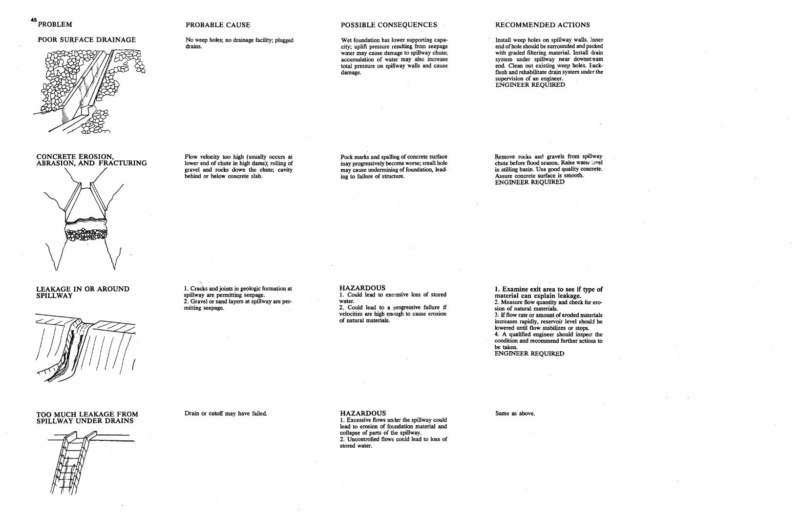
45 PROBLEM
POOR SURFACE DRAINAGE
CONCRETE EROSION, ABRASION, AND FRACTURING
LEAKAGE IN OR AROUND SPILLWAY
TOO MUCH LEAKAGE FROM SPILLWAY UNDER DRAINS
PROBABLE CAUSI;:
No weep holes; no drainage facility; plugged drains.
Flow velocity too high (usually occurs at lower end of chute in high dams); rolling of gravel and rocks down the chute; cavity behind or below concrete slab.
I . Cracks and joints in geologic formation at spillway are permitting seepage. 2. Gravel or sand layers at spillway are per
. mitring seepage.
Drain or cutoff may have failed
POSsrniE CONSEQUENCES
Wet foundation has lower supporting capacity; uplift pressure resulting from seepage water may cause damage to spillway chute; accumulation of water may also increase total pressure on spillway walls and cause damage.
Pock marks and spalling of concrete surface inay progressively bec.ome worse; small hole may cause undermining of foundation, leading to failure of structure.
HAZARDOUS I. Could lead to exc:r~ssive Joss of stored water. 2. Could lead to a progressive failure if velocities are high enough to cause erosion of natural materials.
HAZARDOUS I. Excessive flows under the spillway could lead to erosion of foundation material and collapse of parts of the spillway. 2. Uncontrolled flows could lead to loss of stored water.
RECOMMENDED ACTIONS
Install weep holes on spillway walls. Inner end ofhole should be surrounded and packed with graded filtering material. Install drain system under spillway near downst:eam end Clean out existing weep holes. I•ackflush and rehabilitate drain system under the supervision of an engineer. ENGINEER REQUIRED
Remove rocks and gravels from spillway chute before flood season. Raise waie1· :::•!el in stilling basin. Use good quality concrete. Assure concrete surface is smooth. ENGINEER REQUIRED
I. Examine exit area to see if type of material can explain leakage. 2. Measure flow quantity and check for erosion of natural materials. 3. Ifflow rate or amount of eroded materials increases rapidly, reservoir level shoul:l be lowered until flow stabilizes or stops. 4. A qualified engineer should inspect the condition and recommend further actions to be taken. ENGINEER REQUIRED
Same as above.
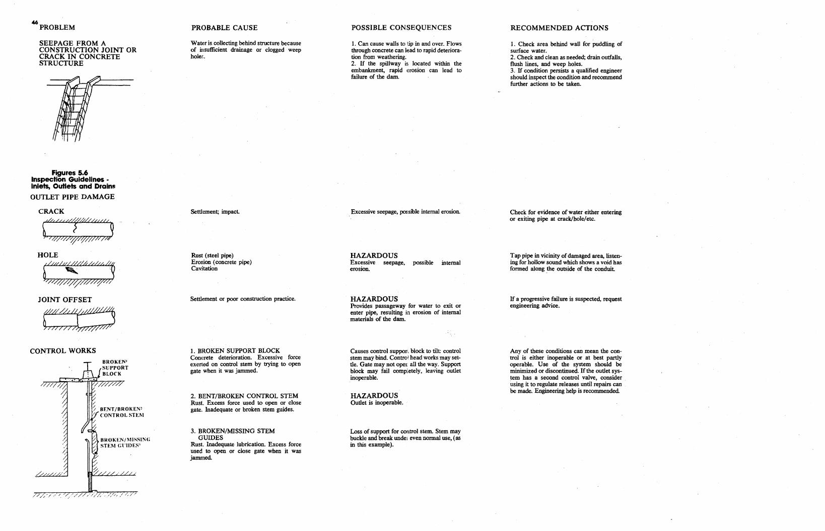
46 . PROBLEM
SEEPAGE FROM A CONSTRUCTION JOINT OR CRACK IN CONCRETE STRUCTURE
c;;r;:J
/ // /,
~
BF.NT/BROKEN2 CONTROL STD!
BROKEN/l\11SSING STEl\1 Gl 'IDES'
Figures 5.6 Inspection Guidelines Inlets, Outlets and Drains
OUTLET PIPE DAMAGE
CRACK
JOINT OFFSET
CONTROL WORKS
PROBABLE CAUSE
Wat1!r is collecting behind structure because of iusufficient drainage or clogged weep hole::.
Settlement; impact
Rust (steel pipe) Erosion (concrete pipe) Cavitation
Settlement or poor construction practice.
1. BROKEN SUPPORT BLOCK Concrete deterioration. Excessive force exerted on control stem by trying to open gate when it was jammed.
2. BENT/BROKEN CONTROL STEM Rust. Excess force used to open or close gate. Inadequate or broken stem guides.
3. BROKEN/MISSING STEM GUIDES
Rust. Inadequate lubrication. Excess force used to open or close gate when it was jammed
POSSIBLE CONSEQUENCES
1. Can cause walls to tjp in and over. Flows through concrete can lead to rapid deterioration from weathering. 2. If the spillway is located within the embankment, rapid erosion can lead to failure of the dam.
Excessive seepage, possible internal erosion.
HAZARDOUS Excessive seepage, possible internal erosion.
HAZARDOUS Provides passageway for water to exit or enter pipe, resulting fa erosion of internal materials of the dam.
Causes control suppon block to tilt: control stem may bind. Control. head works may settle. Gate may not oper.. all the way. Support block may fail completely, leaving outlet inoperable.
HAZARDOUS Outlet is inoperable.
Loss of support for control stem. Stem may buckle and break undei even normal use, (as in this example).
RECOMMENDED ACTIONS
1. Check area behind wall for puddling of surface water. 2. Check and clean as needed; drain outfalls, flush lines, and weep holes. 3. If condition persists a qualified engineer should inspect the condition and recommend further actions to be taken.
Check for evidence of water either entering or exiting pipe at crack/hole/etc.
Tap pipe in vicinity of damaged area, listening for hollow sound which shows a void has formed along _the outside of the conduit
If a progressive failure is suspected, request engineering advice.
Any of these conditions can mean the control is either inoperable or at best partly operable. Use of the system should be minimized or discontinued. If the outlet system has a second control valve, consider using it to regulate releases until repairs can be made. Engineering help is recommended.
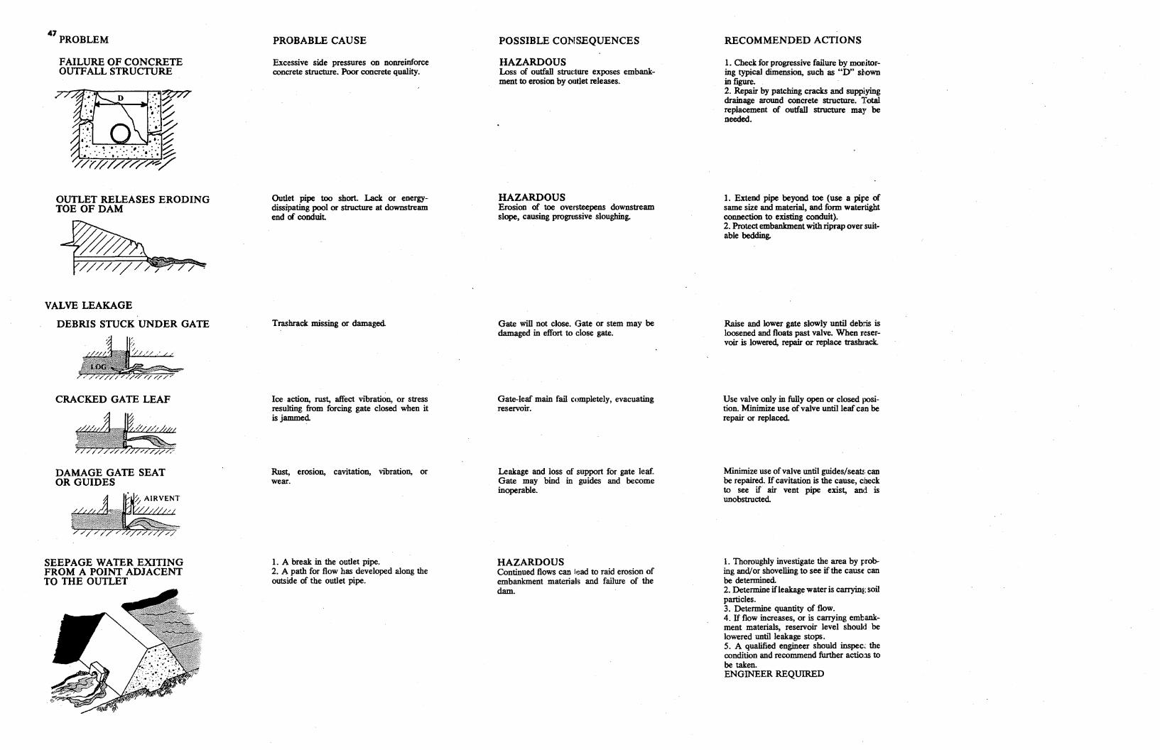
47 PROBLEM
FAILURE OF CONCRETE OUTFALL STRUCTURE
OUTLET RELEASES ERODING TOE OF DAM
VALVE LEAKAGE
DEBRIS STUCK UNDER GATE
CRACKED GATE LEAF
DAMAGE GATE SEAT OR GUIDES
SEEPAGE WATER EXITING FROM A POINT ADJACENT TO THE OUTLET
PROBABLE CAUSE
Excessive side pressures on nonreinforce concrete structure. Poor concrete quality.
Outlet pipe too short. Lack or energydissipating pool or structure at downstream end of conduit
Trashrack missing or damaged
Ice action, rust, affect vibration, or stress resulting from forcing gate closed when it is jammed
Rust, erosion, cavitation, vibration, or wear.
1. A break in the outlet pipe. 2. A path for flow has developed along the outside of the outlet pipe.
POSSIBLE CONSEQUENCES
HAZARDOUS Loss of outfall struc:ture exposes embankment to erosion by outlet releases.
HAZARDOUS Erosion of toe ove.rsteepens downstream slope, causing progrnssive sloughing.
Gate will not close. Gate or stem may be damaged in effort to close gate.
Gate-leaf main fail completely, evacuating reservoir.
Leakage and loss of support for gate leaf. Gate may bind in guides and become inoperable.
HAZARDOUS Continued flows can lead to raid erosion of embankment materials and failure of the dam.
RECOMMENDED ACTIONS
1. Check for progressive failure by monitoring typical dimension, such as "D" shown in figure. 2. Repair by patching cracks and supplying drainage around concrete structure. Total replacement of outfall structure may be needed.
1. Extend pipe beyond toe (use a pire of same size and material, and form watertight connection to existing conduit}. 2. Protect embankment with riprap over suitable bedding.
Raise and lower gate slowly until debris is loosened and floats past valve. When reservoir is lowered, repair or replace trashrack..
Use valve only in fully open or closed position. Minimize use ofvalve until leaf can be repair or replaced.
Minimize use ofvalve until guides/sea~; can be repaired. Ifcavitation is the cause, check to see if air vent pipe exist, and is unobstructed
1. Thoroughly investigate the area by probing and/or shovelling to see ifthe cause can be determined. 2. Determine if leakage water is carrying soil particles. 3. Determine quantity of flow. 4. If flow increases, or is carrying embankment materials, reservoir level should be lowered until leakage stops. 5. A qualified engineer should inspec~ the condition and recommend further actio:1s to be taken. ENGINEER REQUIRED

:mrmr
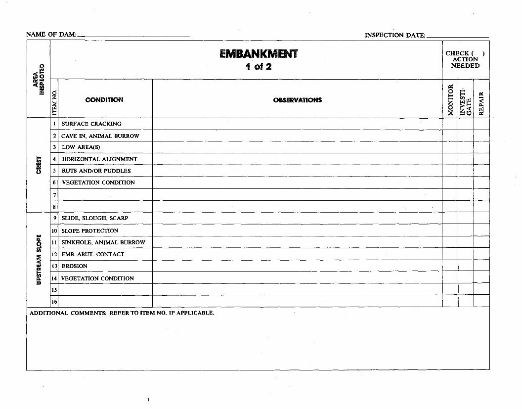
1
2
3
4
5
6
7
8
9
11
NAME OF DAM: _____________ INSPECTION DATE: _______
EMBANKMENT 1of2
OBSERVATIONS
CHECK ( ) ACTION NEEDED
~ ...:.0 ~!--<~ rll~ -<-z ~!--<
0 >< "" :::e ~t!> ~
c :ti ti =~0
!:
ti 1111 AC ()
Ill Q,
g en :Ii! :ti i QI
:I
d z ::E ~ !:::
10
12
13
14
15
16
CONDITION
SURFACE CRACKING
CAVE IN, ANIMAL BURROW
LOW AREA(S)
HORIZONTAL ALIGNMENT
RUTS AND/OR PUDDLES
VEGETATION CONDffiON
SLIDE, SLOUGH, SCARP
SLOPE PROTECTION
SINKHOLE, ANIMAL BURROW
EMB.-ABUT. CONT ACT
EROSION
VEGETATION CONDITION
ADDITIONAL COMMENTS: REFER TO ITEM NO. IF APPLICABLE.
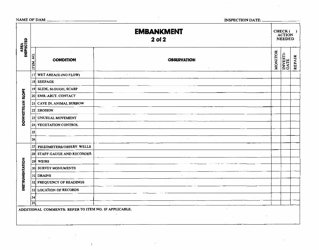
0
21
NAME OF DAM: ______________ INSPECTION DATE: ________
CONDITION
WET AREA(S) (NO FLOW)
SEEPAGE
SLIDE, SLOUGH, SCARP
EMB.-ABUT. CONTACT
CAVE IN, ANIMAL BURROW
EROSION
UNUSUAL MOVEMENT
VEGETATION CONTROL
PIEZOMETERS/OBSERV. WELLS
STAFF GAUGE AND RECORDER
WEIRS
SURVEY MONUMENTS
DRAINS
FREQUENCY OF READINGS
LOCATION OF RECORDS
EMBANKMENT 2of2
OBSERVATION
CHECK( ) ACTION NEEDED
=: ...:..0 ix:r-<r-< ........ rll~ <z ~r-< r:i.><0 ~ ~C!> ~
Q
~I!CllC£ -c~
!
Ill A.
9 en :E =5 at t;
§ :z
z: 0 ~ ...z: Ill
:E :::. fSI! t; !
z ~ ~
!::::
17
18
19
20
22
23
24
25
26
27
28
29
30
31
32
33
34
35
ADDITIONAL COMMENTS: REFER TO ITEM NO. IF APPLICABLE.
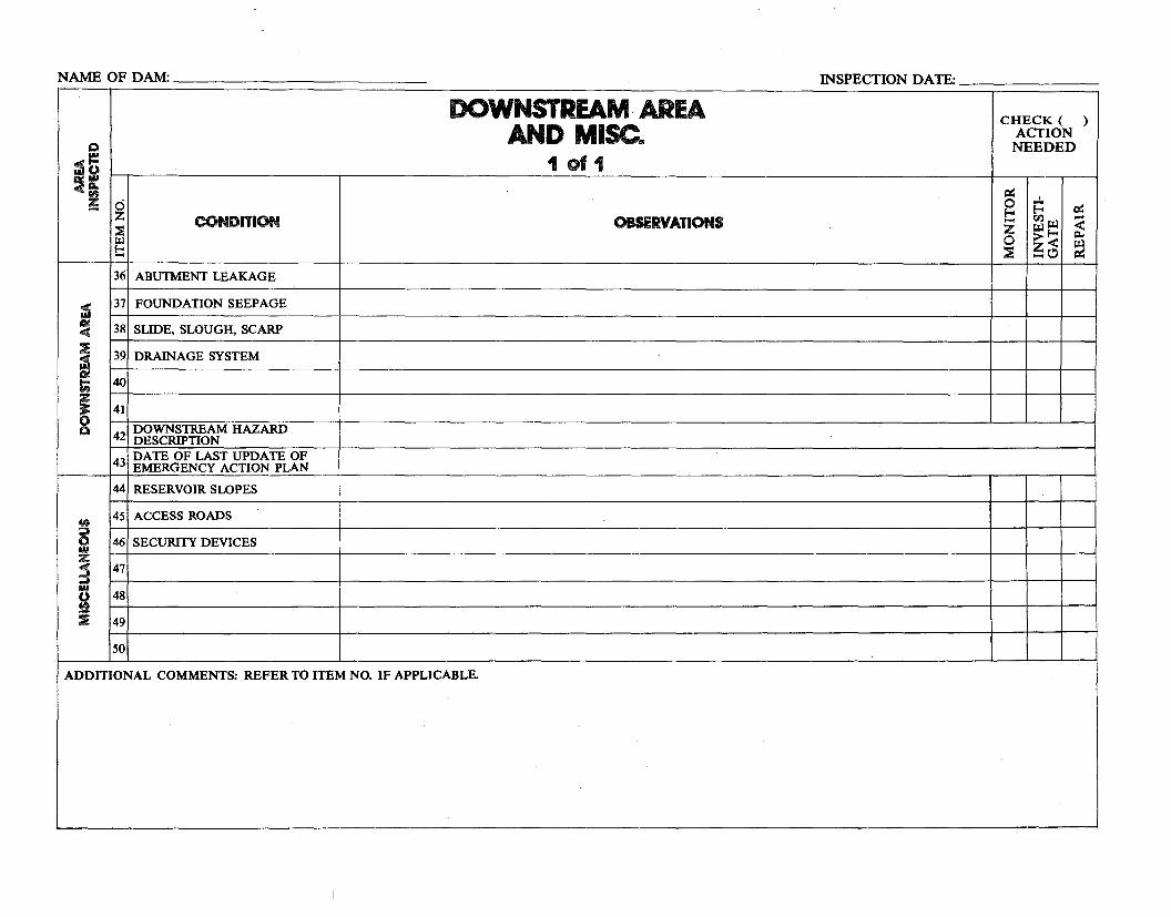
TE:------
CHECK ( ) ACTIONNEEDED
c:ic:: ..:.0~ c:x:~ ....tl.l IJ.l <z IJ.l~ r:i..0 ><
~~ ~c:>
NAME OF DAM: _____________ INSPECTION DA
DOWNSTREAM AREA AND MISC ..
" 1of1:5~ =· d!:: z
:::!1 CONDITION OBSERVATIONS
i:z.i t: 36 ABUTMENT LEAKAGE
37 FOUNDATION SEEPAGE:5 11:11: 38 SLIDE, SLOUGH, SCARP
::IE"" 39 DRAINAGE SYSTEM:5 Di
40In z 41
42 DOWNSTREAM HAZARD DESCRIPTION
43 DATE OF LAST UPDATE OF EMERGENCY ACTION PLAN
~
44 RESERVOIR SWPES
45 ACCESS ROADS => .,, 0 46 SECURITY DEVICES IM z
47 ~ IN
48fl i 49
50
ADDITIONAL COMMENTS: REFER TO ITEM NO. IF APPLICABLE.
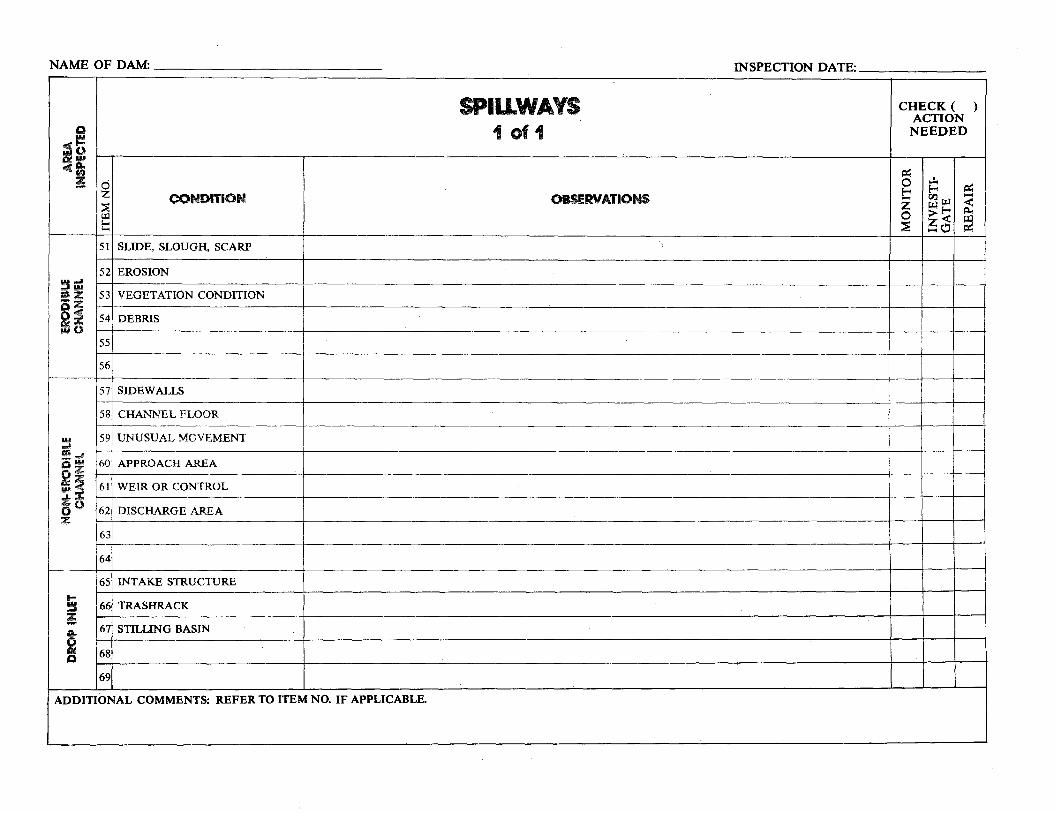
CHECK ( ) ACTION NEEDED
..:.0== !-!-.... ==r:l.l~z i:x:l E--< -<p.
0 >< ~ '1 ~o
== 51
55
56
63
64
NAME OF DAM: ______________ INSPECTION DA
;§ Ci Ill
-CD; !
~=• :z-:z o~ ~o
~._, g~ g:z -~ zo0z:
.... !I !
2 A.
Ci
d z ~ w t:
52
53
54
57
58
59
60
61
62
65
68
69
CONDITION
SLIDE, SLOUGH, SCARP
EROSION
VEGETATION CONDITION
DEBRIS
SIDEWALLS
CHANNEL FLOOR
UNUSUAL MOVEMENT
APPROACH AREA
WEIR OR CONTROL
DISCHARGE AREA
INTAKE STRUCTURE
TRASHRACK
STILLING BASIN
SPIU.WAYS 1of1
OBSERVATIONS
TE:------
ADDITIONAL COMMENTS: REFER TO ITEM NO. IF APPLICABLE.
66
67
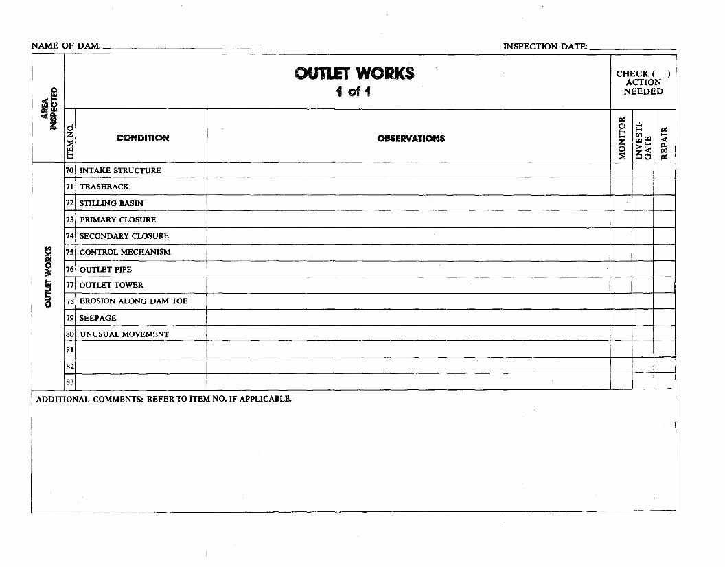
CHECK ( )ACTION NEEDED
ex: ..:. ~~ ...... rn~'""' <z
>< ~~'""' 0 ~Cl ~~
0
70
71
72
73
75
77
81
83
NAME OF DAM: _____________ INSPECTION DATE: _______
Q
:s= =~
!
~ &:!IC
~ .... ~ ....:::» 0
d z ::s ~ t::
74
76
78
79
80
82
CONDITION
INTAKE STRUCTURE
TRASHRACK
STILLING BASIN
PRIMARY CLOSURE
SECONDARY CLOSURE
CONTROL MECHANISM
OUTLET PIPE
OUTLET TOWER
EROSION ALONG DAM TOE
SEEPAGE
UNUSUAL MOVEMENT
OUTLET WORKS 1of1
OBSERVATIONS
ADDITIONAL COMMENTS: REFER TO ITEM NO. IF APPLICABLE.
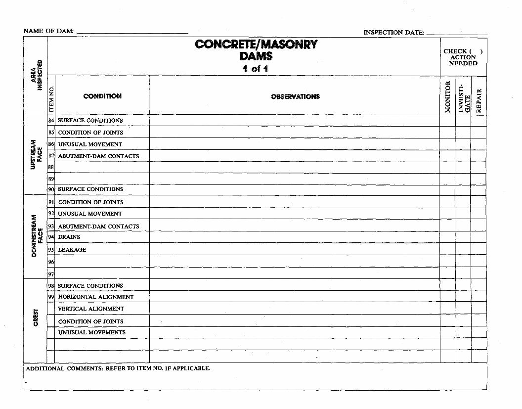
CHECK ( ) ACTION NEEDED
c:ie: ..:..0 ~ -'""'~~ <-z'""'
>~ ~
~ 0
2:: \!) ~
85
86
88
89
90
91
93
95
96
97
99
NAME OF DAM: ______________ INSPECTION DATE: _______
Q
;st-Ml
GC2 ~i
;~iu. :II
:IE ~ Clil llM
i~;tu.
8
t; IN CliC ()
d z ~ Ill I::
84
87
92
94
98
CONDITION
SURFACE CONDIDONS
CONDITION OF JOINTS
UNUSUAL MOVEMENT
ABUTMENT-DAM CONT ACTS
SURF ACE CONDIDONS
CONDIDON OF JOINTS
UNUSUAL MOVEMENT
ABUTMENT-DAM CONTACTS
DRAINS
LEAKAGE
SURFACE CONDIDONS
HORIZONTAL ALIGNMENT
VERTICAL ALIGNMENT
CONDIDON OF JOINTS
UNUSUAL MOVEMENTS
CONCRETE/MASONRY DAMS 1 of 1
OBSERVATIONS
ADDITIONAL COMMENTS: REFER TO ITEM NO. IF APPLICABLE.

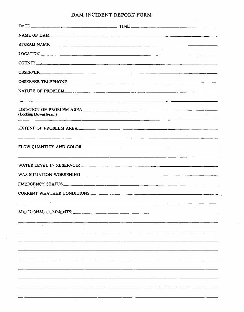
DAM INCIDENT REPORT FORM
NAME OF DAM_____________________________
STREAM NAME_____________________________
LOCATION_____________________________~
COUNTY _______________________________
OBSERVER-----------------------------~
OBSERVER TELEPHONE__________________________
NATURE OF PROBLEM__________________________
LOCATION OF PROBLEM AREA_______________________ (Looking Downstream)
EXTENT OF PROBLEM AREA________________________
FLOW QUANTITY AND COLOR_______________________
WATER LEVEL IN RESERVOIR_______________________
WAS SITUATION WORSENING ----------------------
EMERGENCY STATUS ___________________________
CURRENT WEATHER CONDITIONS ______________________
ADDITIONAL COMMENTS: _________________________
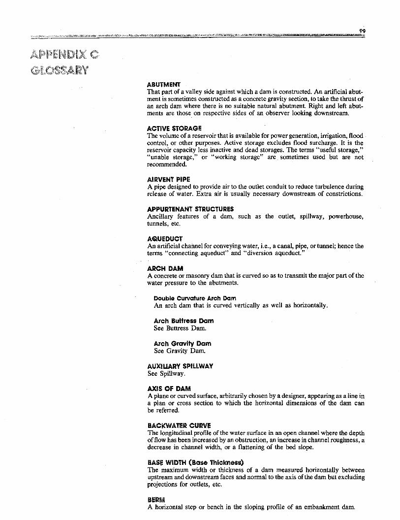
ABUTMENT That part of a valley side against which a dam is constructed. An artificial abutment is sometimes constructed as a concrete gravity section, to take the thrust of an arch dam where there is no suitable natural abutment Right and left abutments are those on respective sides of an observer looking downstream.
ACTIVE STORAGE The volume of a reservoir that is available for power generation, irrigation, flood control, or other purposes. Active storage excludes flood surcharge. It is the reservoir capacity less inactive and dead storages. The terms "useful storage," "unable storage," or "working storage" are sometimes used but are not recommended.
AIRVENT PIPE A pipe designed to provide air to the outlet conduit to reduce turbulence during release of water. Extra air is usually necessary downstream of constrictions.
APPURTENANT STRUCTURES Ancillary features of a dam, such as the outlet, spillway, powerhouse, tunnels, etc.
AQUEDUCT An artificial channel for conveying water, i.e., a canal, pipe, or tunnel; hence the terms "connecting aqueduct" and "diversion aqueduct."
ARCH DAM A concrete or masonry dam that is curved so as to transmit the major part of the water pressure to the abutments.
Double Curvature Arch Dam An arch dam that is curved vertically as well as horizontally.
Arch Buttress Dam See Buttress Dam.
Arch Gravity Dam See Gravity Dam.
AUXILIARY SPILLWAY See Spillway.
AXIS OF DAM A plane or curved surface, arbitrarily chosen by a designer, appearing as a line in a plan or cross section to which the horizontal dimensions of the dam can be referred.
BACKWATER CURVE The longitudinal profile of the water surface in an open channel where the depth of flow has been increased by an obstruction, an increase in channel roughness, a decrease in channel width, or a flattening of the bed slope.
BASE WIDTH (Base Thickness) The maximum width or thickness of a dam measured horizontally between upstream and downstream faces and normal to the axis ofthe dam but excluding projections for outlets, etc.
BERM A horizontal step or bench in the sloping profile of an embankment dam.
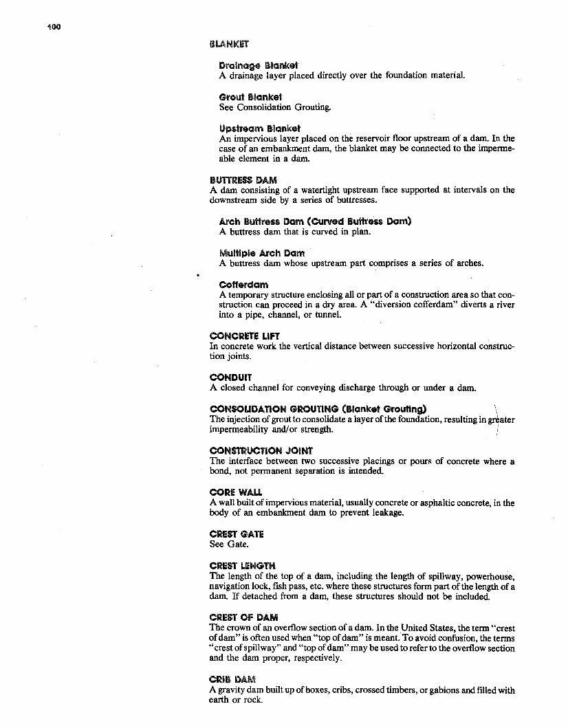
100
BIANKET
Drainage Blanket A drainage layer placed directly over the foundation material.
Grout Blanket See Consolidation Grouting.
Upstream Blanket An impervious layer placed on the reservoir floor upstream of a dam. In the case of an embankment dam, the blanket may be connected to the impermeable element in a dam.
BUTIRESS DAM A dam consisting of a watertight upstream face supported at intervals on the downstream side by a series of buttresses.
Arch Buttress Dam (Curved Buttress Dam) A buttress dam that is curved in plan.
Multiple Arch Dam A buttress dam whose upstream part comprises a series of arches.
Cofferdam A temporary structure enclosing all or part of a construction area so that construction can proceed in a dry area. A "diversion cofferdam" diverts a river into a pipe, channel, or tunnel.
CONCRETE LIFT In concrete work the vertical distance between successive horizontal construction joints.
CONDUIT A closed channel for conveying discharge through or under a dam.
CONSOLIDATION GROUTING (Blanket Grouting) \ The injection ofgrout to consolidate a layer of the foundation, resulting in greater impermeability and/ or strength. I
CONSTRUCTION JOINT The interface between two successive placings or pours of concrete where a bond, not permanent separation is intended.
CORE WAll A wall built of impervious material, usually concrete or asphaltic concrete, in the body of an embankment dam to prevent leakage.
CREST GATE See Gate.
CREST LENGTH The length of the top of a dam, including the length of spillway, powerhouse, navigation lock, fish pass, etc. where these structures form part of the length of a dam. If detached from a dam, these structures should not be included.
CREST OF DAM The crown of an overflow section of a dam. In the United States, the term "crest ofdam" is often used when "top ofdam" is meant. To avoid confusion, the terms "crest of spillway" and "top ofdam" may be used to refer to the overflow section and the dam proper, respectively.
CRIB DAM A gravity dam built up ofboxes, cribs, crossed timbers, or gabions and filled with earth or rock.
101
CULVERT (a) A drain or waterway built transversely under a road, railway, or embankment, usually consisting of a pipe or covered channel of box section. (b) A gallery or waterway constructed through any type ofdam, which is normally dry but is used occasionally for discharging water; hence the terms "scour culvert," "drawoff culvert," and "spillway culvert."
CURTAIN See Grout curtain
CURVED BUTTRESS DAM (Arch Buttress Dam) See Buttress Dam.
CURVED GRAVITY DAM See Gravity Dam.
CUTOFF An impervious construction or material which reduces seepage or prevents it from passing through foundation material.
CUTOFF TRENCH An excavation later to be filled with impervious material to form a cutoff. Sometimes used incorrectly to describe the cutoff itself.
CUTOFF WALL A wall of impervious material (e.g., concrete, asphaltic concrete, steel sheet piling) built into the foundation to reduce seepage under the dam.
DAM A barrier built across a watercourse for impounding or diverting the flow of water.
DEAD STORAGE The storage that lies below the invert of the lowest outlet and that, therefore, cannot be withdrawn from the reservoir.
DESIGN FLOOD See Spillway Design Flood.
DIAMOND HEAD BUlTRESS DAM See Buttress Dam.
DIAPHRAGM See Membrane.
DIKE (Levee) A long low embankment whose height is usually less than 4 to 5 meters and whose length is more than 10 or 15 times the maximum height. Usually applied to embankments or structures built to protect land from flooding. ffbuilt of concrete or masonry the structure is usually referred to as a flood wall. Also used to describe embankments that block areas on a reservoir rim that are lower than the top ofthe main dam and that are quite long. In the Mississippi River basin, where the old French word levee has survived, the term now applies to flood protecting embankments whose height can average up to 10 to 15 meters.
DIVERSION CHANNEL CANAL, OR TUNNEL A waterway used to divert water from its natural course. These terms are generally applied to temporary structures such as those designed to bypass water around a dam site during construction. "Channel' is normally used instead of "canal" when the waterway is short. Occasionally these terms are applied to permanent structures.
DRAINAGE AREA An area that drains naturally to a particular point on a river.
102
DRAINAGE LAYER OR BLANKET A layer of permeable material in a dam to relieve pore pressure or to facilitate drainage of fill.
DRAINAGE WELLS (Rellef Well) A vertical well or borehole, usually downstream of impervious cores, grout curtains, or cutoffs, designed to collect and direct seepage through or under a dam to reduce uplift pressure under or within a dam. A line of such wells forms a drainage curtain.
DRAWDOWN The lowering of water surface level due to release of water from a reservoir.
EARTH DAM OR EARTHFILL DAM See Embankment Dam.
EMBANKMENT A slope of fill material, usually earth or rock, that is longer than it is high. The sloping side of a dam.
Embankment Dam (Fiii Dam) Any dam constructed of excavated natural materials or of industrial waste materials.
Earth Dam (Earthflll Dam) An embankment dam in which more than 50% ofthe total volume is formed of compacted fine-grained material obtained from a borrow area.
Homogeneous Earthflll Dam An embankment dam constructed of similar earth material throughout, except internal drains or drainage blankets; distinguished from a zoned earthfill dam.
Hydraulic Fiii Dam An embankment dam constructed of materials, often dredged, that are conveyed and placed by suspension in flowing water.
Rockflll Dam An embankment dam in which more than 50% of the total volume comprises compacted or dumped pervious natural or crushed rock.
Rolled Fiii Dam An embankment dam of earth or rock in which the material is placed in layers and compacted by using rollers or rolling equipment.
Zoned Embankment Dam An embankment dam, of which is composed of zones of selected materials having different degrees of porosity, permeability, and density.
EMERGENCY ACTION PLAN A predetermined plan of action to be taken to reduce the potential for property damage and loss of lives in an area affected by a dam break.
EMERGENCY GATE A standby or reserve gate used only when the normal means of water control are not available.
EMERGENCY SPILLWAY See Spillway.
ENERGY/DISSIP.ATING VALVE Any device constructed in a waterway to reduce or destroy the energy of fastflowing water.
t03
EPICENTER· The point on the earth's surf ace directly above the focus of an earthquake.
FACE The external surface of a structure, e.g., the surface of a wall of a dam.
FACING With reference to a wall or concrete dam, a coating of material, masonry or brick, for architectural or protection purposes, e.g., stonework facing, brickwork facing. With reference to an embankment dam, an impervious coating or face on the upstream slope of the dam.
FAILURE The uncontrolled release of water from a dam.
FILTER (Fiiter Zone) A band or zone ofgranular material that is incorporated into a dam and is graded (either naturally or by selection) so as to allow seepage to flow across or down the filter without causing the migration of material from zones adjacent to the filter.
FWHBOARDS A length oftimber, concrete, or steel placed on the crest of a spillway to raise the retention water level but that may be quickly removed in the event of a flood either by a tripping device or by deliberately designed failure of the flashboard or its supports.
FLOODPLAIN An area adjoining a body of water or natural stream that has been or may be covered by flood water.
FLOODPLAIN MANAGEMENT A management program to reduce the consequences of flooding - either by natural runoff or by dam failure - to existing and future properties in a floodplain.
FLOOD ROUTING The determination of the attenuating effect of storage on a flood passing through a valley, channel, or reservoir.
FLOOD SURCHARGE The volume or space in a reservoir between the controlled retention water level and the maximum water level. Flood surcharge cannot be retained in the reservoir but will flow over the spillway until the controlled retention water level is reached. (The term "wet freeboard" for describing the depth of flood surcharge is not recommended; see Freeboard).
FLOOD WALL A concrete wall constructed adjacent to a stream for the purpose of preventing flooding of property on the landward side of the wall; normally constructed in lieu ofor to supplement a levee where the land required for levee construction is expensive or not available.
FOUNDATION OF DAM The natural material on which the dam structure is placed.
FREEBOARD The vertical distance between a stated water level and the top of a dam. "Net freeboard," "dry freeboard," "flood freeboard," or "residual freeboard" is the vertical distance between the estimated maximum water level and the top of a dam. "Gross freeboard" or "total freeboard" is the vertical distance between the maximum planned controlled retention water level and the top of a dam. (That part ofthe "gross freeboard" attributable to the depth offlood surcharge is sometimes referred to as the "wet freeboard," but this term is not recommended; it is preferable that freeboard be used with reference to the top of the dam.
GAU.ERV (a) A passageway within the body of a dam or abutment; hence the terms "grouting gallery," "inspection gallery," and "drainage gallery." (b) A long and rather narrow hall; hence the following tenns for a power plant "valve gallery," "transformer gallery," and "busbar gallery."
GATE A device in which a leaf or member is moved across the waterway from an external position to control or stop the flow.
Bulkhead Gate A gate used either for temporary closure ofa channel or conduit to empty it for inspection or maintenance or for closure against flowing water when the head difference is small, e.g., for diversion tunnel closure. Although a bulkhead gate is usually opened and closed under nearly balanced pressures, it nevertheless may be capable of withstanding a high pressure differential when in the closed position.
Crest Gate (Splllway Gate) A gate on the crest of a spillway to control overflow or reservoir water level.
Emergency Gate A standby or reserve gate used only when the normal means ofwater control is not available.
Fixed Wheel Gate (Fixed Roller Gate, Fixed Axle Gate) A gate having wheels or rollers mounted on the end posts of the gate. The wheels bear against rails fixed in side grooves or gate guides.
Flap Gate A gate hinged along one edge, usually either the top or bottom edge. Examples of bottom-hinged flap gates are tilting gates and belly gates, so-called due to their shape in cross section.
Flood Gate A gate to control flood release from a reservoir.
Guard Gate (Guard Valve) A gate or valve that operates fully open or closed. It may function as a secondary device for shutting off the flow ofwater in case the primary closure device becomes inoperable, but is usually operated under balanced pressure, noflow conditions.
outlet Gate A gate controlling the outflow of water from a reservoir.
Radlal Gate (Tainter Gate) A gate with a curved upstream plate and radial arms hinged to piers or other supporting structures.
Regulatlng Gate (Regulatlng Valve) A gate or valve that operates under full pressure and flow conditions to throttle and vary the rate of discharge.
Slide Gate (Sluice Gate) A gate that can be opened or closed by sliding it in supporting guides.
t05
GRAVITY DAM A dam constructed of concrete and/or masonry that relies on its weight for stability.
Arch Gravity Dam An arch dam in which part of the water pressure is transmitted to the abutments by horizontal thrust and part to the foundation by cantilever action.
CUrved Gravity Dam A gravity dam that is curved in plan.
Hollow Gravity Dam (Cellular Gravity Dam) Adam that has the outward appearance of a standard gravity dam but that is of hollow construction.
GROSS STORAGE (Reservoir Capacity (Gross Capacity of Reservoir) The gross capacity of a reservoir from the river bed up to maximum controlled retention water level. It includes active, inactive, and dead storage.
GROUT BLANKET See Blanket
GROUT CAP A concrete pad or wall constructed to facilitate pressure grouting of the grout curtain beneath it.
GROUT CURTAIN (Grout Cutoff) A barrier produced by injecting grout into a vertical zone, usually narrow horizontally, in the foundation to reduce seepage under a dam.
HEIGHT ABOVE LOWEST FOUNDATION The maximum height from the lowest point of the general foundation to the top of the dam.
HYDRAULIC HEIGHT The height to which water rises behind a dam and the difference between the lowest point in the original streambed at the axis of the dam and the maximum controllable water surface.
HYDROGRAPH A graphic representation of discharge, stage, or other hydraulic property with respect to time for a particular point on a stream. (At times the term is applied to the phenomenon the graphic representation describes; hence a flood hydrograph is the passage of a flood discharge past the observation point.)
INACTIVE STORAGE The storage volume of a reservoir measured between the invert level of the lowest outlet and minimum operating level.
INCLINOMETER (lnclometer) An instrument, usually consisting of a metal or plastic tube inserted in a drill hole and a sensitized monitor either lowered into the tube or fixed within the tube. This measures at different points the tube's inclination to the vertical. By integration, the lateral position at different levels of the tube may be found relative to a point, usually the top or bottom ofthe tube, assumed to be fixed. The system may be used to measure settlement.
INTAKE Any structure in a reservoir, dam, or river through which water can be drawn into an aqueduct.
INTENSITY SCALE An arbitrary scale used to describe the severity ofearthquake-induced shaking at a particular place. The scale is not based on measurement but on direct observation. Several scales are used (e.g., the Modified Mercalli scale,the MSK scale) all with grades indicated by Roman numerals from I to XII.
INTERNAL EROSION See Piping.
INUNDATION MAP A map delineating the area that would be inundated in the event of a dam failure.
LEAKAGE Uncontrolled loss of water by flow through a hole or crack.
LINING With reference to a canal, tunnel, shaft, or reservoir, a coating of asphaltic concrete, reinforced or unreinforced concrete, shotcrete, rubber or plastic to provide watertightness, prevent erosion, reduce friction, or support the periphery of the structure. May also refer to lining, such as steel or concrete, of outlet pipe or conduit.
UVE STORAGE The sum of active and inactive storage volumes. When there is no inactive storage, as in some irrigation reservoirs, the terms "live storage" and "active storage" are equivalent.
LOW LEVEL OUTLET (Bottom Outlet) An opening at a low level from a reservoir generally used for emptying or for scouring sediment and sometimes for irrigation releases.
MAGNITUDE (see also Richter Scale) A rating of an earthquake independent of the place of observation. It is calculated from seismographic measurements and is properly expressed in ordinary numbers and decimals based on a logarithmic scale. Each higher number expresses an amount ofearthquake energy that is 10 times greater than that expressed by the preceding lower number, e.g., a magnitude 6 earthquake has 10 times more energy than a magnitude 5.
MASONRY DAM A dam constructed mainly of stone, brick, or concrete blocks that may or may not be joined with mortar. A dam having only a masonry facing should not be referred to as a masonry dam.
MAXIMUM CREDIBLE EARTHQUAKE (MCE) The severest earthquake that is believed to be possible at a site on the basis of geologic and seismological evidence. It is determined by regional and local studies including a complete review of all historic earthquake data of events sufficiently nearby to affect the site, all faults in the area, and attenuations due to faults to the site.
MAXIMUM CROSS SECTION OF DAM A cross section of a dam at the point of maximum height of the dam.
MAXIMUM WATER LEVEL The maximum water level, including flood surcharge, the dam is designed to withstand.
MEMBRANE (Diaphragm) A sheet or thin zone or facing made of a flexible material that is sometimes referred to as a diaphragm wall or diaphragm.
107
NUNIMUM OPERATING LEVEL The lowest level to which the reservoir is drawn down under normal operating conditions.
MORNING GLORY SPIUWAY See Spillway.
NORMAL WATER LEVEL For a reservoir with a fixed overflow sill the lowest crest level of that sill. For a reservoir whose outflow is controlled wholly or partly by movable gates, siphons or other means, it is the maximum level to which water may rise under normal operating conditions, exclusive of any provision for flood surcharge.
OPERATING BASIS EARTHQUAKE A hypothetical earthquake used for design purposes. A more moderate standard than the Maximum Credible Earthquake (see), it is based on regional and local geology and seismology studies and is considered likely to occur during the life of the dam.
ONE-HUNDRED YEAR (100-Year) EXCEEDANCE INTERVAL The flood magnitude expected to be equalled or exceeded on the average of once in 100 years. It may also be expressed as an exceedance frequency with a percent chance of being exceeded in any given year.
OUTLET An opening through which water can be freely discharged from a reservoir.
OVERFLOW DAM (Overtoppable Dam) A dam designed to be overtopped
PARAPET WAU. A solid wall built along the top of a dam for ornament, for the safety of vehicles and pedestrians, or to prevent overtopping.
PEAK FLOW The maximum instantaneous discharge that occurs during a flood. It is coincident with the peak of a flood hydrograph.
PERVIOUS ZONE A part of the cross section of an embankment dam comprising material of high permeability.
PHREATIC SURFACE The free surf ace of groundwater at atmospheric pressure.
PIEZOMETER An instrument for measuring pore water pressure within soil, rock, or concrete.
PIPING The progressive development of internal erosion by seepage, appearing downstream as a hole or seam discharging water that contains soil particles.
PORE PRESSURE The interstitial pressure of water within a mass of soil rock, or concrete.
PRESSURE CEU An instrument for measuring pressure within a mass of soil, rock, or concrete or at an interlace between one and the other.
PRESSURE RELIEF PIPES Pipes used to relieve uplift or pore water pressure in a dam foundation or in the dam structure.
'108
PROBABLE MAXIMUM FLOOD (PMF) A flood that would result from the most severe combination of critical meteorologic and hydrologic conditions possible in the region.
One-Half PMF A flood with a peak flow equal to one-half of the peak flow of a probable maximum flood.
PROBABLE MAXIMUM PRECIPITATION (PMP) The maximum amount and duration of precipitation that can be expected to occur on a drainage basin.
PUMPED STORAGE RESERVOIR A reservoir filled entirely or mainly with water pumped from outside its natural drainage area.
REGULATING DAM A dam impounding a reservoir from which water is released to regulate the flow in a river.
REUEF WEU. See Drainage Well.
RESERVOIR AREA The surface area of a reservoir when filled to controlled retention water level.
RESERVOIR ROUTING The computation by which the interrelated effects of the inflow hydrograph, reservoir storage, and discharge from the reservoir are evaluated.
RESERVOIR SURFACE The surface of a reservoir at any level.
RICHTER SCALE A scale proposed by C.F. Richter to describe the magnitude of an earthquake by measurements made in well-defined conditions and with a given type of seismograh. The zero of the scale is fixed arbitrarily to fit the smallest recorded earthquakes. The largest recorded earthquake magnitudes are near 8.7 a.nd are the result ofobservations and not an arbitrary upper limit like that ofthe intensity ~·
RIPRAP A layer of large uncoursed stones, broken rock, or precast blocks placed in random fashion on the upstream. slope of an embankment dam, on a reservoir shore, or on the sides of a channel as a protection against wave and ice action. Very large riprap is sometimes referred to as armoring.
RISK ASSESSMENT As applied to dam safety, the process of identifying the likelihood and consequences of dam failure to provide the basis for informed decisions on a course of action.
ROCKFILL DAM See Embankment Dam.
ROU.CRETE A no-slump concrete that can be hauled in dump trucks, spread with a bulldozer or grader, and compacted with a vibratory roller.
SEEPAGE The interstitial movement of water that may take place through a dam, its foundation, or its abutments.
I
109
SEEPAGE COLI.AR A projecting collar, usually of concrete, built around the outside of a pipe, tunnel, or conduit under an embankment dam, to lengthen the seepage path along the outer surface of the conduit.
SIU. (a) A submerged structure across a river to control the water level upstream. (b) The crest of a spillway. ( c) A horizontal gate seating, made of wood, stone, concrete or metal at the invert of any opening or gap in a structure, hence the expressions "gate sill" and "stoplog sill."
SLOPE (a) The side of a hill or mountain. (b) The inclined face of a cutting or canal or embankment. ( c) Inclination from the horizontal. In the Untied States, it is measured as the ratio of the number of units of horizontal distance to the number of corresponding units of vertical distance. The term is used in English for any inclination and is expressed as a percent when the slope is gentle, in which case the term "gradient" is also used.
SLOPE PROTECTION The protection of a slope against wave action or erosion.
SLUICEWAY See low-level outlet.
SPIU.WAY A structure over or through which flood flows are discharged. If the flow is controlled by gates, it is a controlled spillway; ifthe elevation of the spillway crest is the only control, it is an uncontrolled spillway.
Auxlllary Spillway (Emergency Spillway) A secondary spillway designed to operate only during exceptionally large floods.
Fuse Plug Spillway An auxiliary or emergency spillway comprising a low embankment or a natural saddle designed to be overtopped and eroded away during a very rare and exceptionally large flood ..
Primary Spillway (Principal Spillway) The principal or first-used spillway during flood flows.
Shaft Spillway (Morning Glory Spillway) A vertical or inclined shaft into which flood water spills and then is conducted through, under, or around a dam by means of a conduit or tunnel. Ifthe upper part of the shaft is splayed out and terminates in a circular horizontal weir, it is termed a "bellmouth" or "morning glory" spillway.
Side Channel Spillway A spillway whose crest is roughly parallel to the channel immediately downstream of the spillway.
Siphon Spillway A spillway with one or more siphons built at crest level. This type of spillway is sometimes used for providing automatic surface-level regulation within narrow limits or when considerable discharge capacity is necessary within a short period of time.
SPIU.WAY CHANNEL (Spillway Tunnel) A channel or tunnel conveying water from the spillway to the river downstream.
HO
SPILLWAY DESIGN FLOOD (SDF) The largest flood that a given project is designed to pass safely. The reservoir inflow-discharge hydrograph used to estimate the spillway discharge capacity requirements and corresponding maximum surcharge elevation in the reservoir.
STILLING BASIN A basin constructed to dissipate the energy of fast-flowing water, e.g., from a
spillway or bottom outlet, and to protect the river bed from erosion.
STOPLOGS Large logs or timber or steel beams placed on top of each other with their ends held in guides on each side of a channel or conduit providing a cheaper or more easily handled temporary closure than a bulkhead gate.
STORAGE The retention of water or delay of runoff either by planned operation, as in a reservoir, or by temporary filling of overflow areas, as in the progression of a flood crest through a natural stream channel.
STORAGE RESERVOIR A reservoir that is operated with changing water level for the purpose of storing and releasing water.
TAILRACE The tunnel, channel, or conduit that conveys the discharge from the turbine to the river; hence the terms "tailrace tunnel" and "tailrace canal."
TAILWATER LEVEL The level ofwater in the tailrace at the nearest free surface to the turbine or in the discharge channel immediately downstream of the dam.
TOE OF DAM The junction of the downstream face of a dam with the ground surf ace, also referred to as downstream toe. For an embankment dam the junction of the upstream face with ground surface is called the upstream toe.
TOP OF DAM The elevation of the uppermost surface of a dam, usually a road or walkway, excluding any parapet wall, railings, etc.
TOP THICKNESS (Top Width) The thickness or width of a dam at the level of the top of the dam. In general, the term "thickness" is used for gravity and arch dams and "width" is used for other dams.
TRANSITION ZONE (Semlpervlous Zone) A part of the cross section of a zoned embankment dam comprising material of intermediate size between that of an impervious zone and that of a permeable zone.
TRASH RACK A screen located at an intake to prevent the ingress of debris.
TUNNEL A long underground excavation usually having a uniform cross section. Types of tunnel include: headrace tunnel, pressure tunnel, collecting tunnel, diversion tunnel, power tunnel, tailrace tunnel, navigation tunnel, access tunnel, scour tunnel, drawoff tunnel, and spillway tunnel.
UNDERSEEPAGE The interstitial movement of water through a foundation.
1H
UPLIFT The upward pressure in the pores of a material (interstitial pressure) or on the base of a structure.
UPSTREAM BIANKET See Blanket
VALVE A device fitted to a pipeline or orifice in which the closure member is either rotated or moved transversely or longitudinally in the waterway so as to control or stop the flow.
'NATERSHED DIVIDE The divide or boundary between catchment areas (or drainage areas).
'NATERSTOP A strip ofmetal, rubber, or other material used to prevent leakage throughjoints between adjacent sections of concrete.
'NEIR (a) A low dam or wall built across a stream to raise the upstream water level, termed fixed-crest weir when uncontrolled. (b) A structure built across a stream or channel for the purpose of measuring flow, sometimes called ameasuring weir or gauging weir. Types of weir include broad-crested weir, sharp-crested weir, drowned weir, and submerged weir.

113
I
STATE M~NUALS
Arkansas Soil and Water Conservation Commission (1980) Safety Evaluation of Small Earth Dams Little Rock, Arkansas.
Colorado State Engineer's Office, Division of Water Resources (1983) Dam Safety Manual Denver, Colorado.
State of Illinois Department of Water Resources (1980) Guidelines and Forms for Inspection of Illinois Dams, Springfield, Illinois.
Kentucky Natural Resources and Environmental Protection Cabinet, Division of Water Resources (1985) Guidelines for Maintenance and Inspection of Dams in Kentucky.
Michigan Edition, STS Consultants, Dam Safety Guidebook.
North Carolina Department of Natural Resources and Community Development, Division of Land Resources, Land Quality Security Dam Operation Maintenance and Inspection Manual.
North Dakota Dam Design Handbook, North Dakota State Engineer.
Ohio Department of Natural Resources (1983) Operation, Maintenance, and Inspection Manual for Dams, Dikes, and Levees.
Pennsylvania Department of Environmental Resources, Division of Dam Safety ( 1986) A Manual for the Inspection, Maintenance, and Operation of Dams in Pennsylvania.
Virginia State Water Control Board, Bureau of Water Control Management (1983) Safety Evaluation of Small Earth Dams, Information Bulletin 549, Richmond, Virginia.
Wyoming Disaster and Civil Defense Office ( 1984) Dam Safety: A Manual for Private Dam Owners.
Selected Bibliography American Society of Civil Engineers (ASCE)/U.S. Commission on Large Dams (USCOLD) (1975). Lessons from Dam Incidents, USA. New York: ASCE.
American Concrete Institute (ACI) (1968). "Guide for Making A Condition Survey of Concrete In Service", Journal of the American Concrete Institute, Vol. 65, No. 11: ACI.
( 1982). "Materials and General Properties of Concrete." In ACI Manual of Concrete Practice, Part 1. Detroit: ACI.
Bartholomew, C.L., et al (1986). Embankment Dam Instrumentation Manual U.S. Bureau of Reclamation, Washington, D.C., Government Printing Office.
(1987). (To be published.) Concrete Dam Instrumentation Manual, U.S. Bureau of Reclamation, Washington, D.C., Government Printing Office.
4'14
Chief of Engineers ( 197 5). "Recommended Guidelines for Safety Inspection of Dams." National Program of Inspection of Dams, Vol. 1, Appendix D, Washington, D.C., Department of the Army.
Concrete Construction Publication, Inc. (1983). "Four Steps to Successful Concrete Repair." Vol. 28, No. 1. Addison, Illinois: Concrete Construction Publication, Inc.
(1985) "Crack Repair." Vol. 30, No.1. Addison, Illinois: Concrete Constructon Publication, Inc.
Dunnicliff, J. (1981). Measurements Commitee Report, U.S. Committee on large Dams Section VI, Inventory of Geotechnical Instruments, Manufacturers or Suppliers.
Golze, A.R, ed. (1977). Handbook of Dam Engineering, Van Nostrand Reinhold Co., New York.
Graham, W.J. (1983). Dam Failure Warning Effectivness, Denver, Colorado, U.S. Bureau of Reclamation. Unpublished report.
Interagency Committee on Dam Safety, Subcommittee on Emergency Action Planning (1985). Emergency Action Planning Guidelines for Dams, Washington, D.C., Federal Emergency Management Agency.
Interagency Committee on Large Dams (ICOLD) (1969). General Considerations Applicable to Instrumentation for Earth and Rockfill Dams, Committee on Observations of Dam and Models, Bulletin, No. 21, Boston, Massachusetts.
(1981). Automated Observation for Instantaneous Safety Control of Dams and Reservoirs, Bulletin No. 41, Boston, Massachusetts.
International Conference of Building Officials (1979). Uniform Building Code, 1979 Edition, Whittier, California.
Jansen, RB. (1968). A Prescription for Dam Safety- Instrumentation and Surveillance, Conference of College of Engineering, University of California, Berkeley.
( 1980 ). Dams iand Public Safety, U.S. Bureau of Reclamation, !Government Printing Office, Washington, D. C.
Mine Safety and Health Administration, Mine Waste and Geotechnical Engineering Division ( 1984 ). Construction Inspection of Dams and Coal Refuse Embankments, Bruceton Mills, Pennsylvania.
National Association of Conservation Districts "Dam Safety- Who is Responsible?" Slide show produced by National Association of Conservation Districts, Washington, D.C.
National Research Council (1982). Geotechnical Instrumentation for Monitoring Field Performance, Washington, D.C., National Academy Press.
National Research Council, Committee on the Safety of Existing Dams ( 1983 ). Safety of Existing Dams, Evaluation and Improvement, Washington, D.C., National Academy Press.
National Research Council, Committee on Safety Criteria for Dams (1985). Safety of Dams Flood and Earthquake Criteria, Washington, D.C., National Academy Press.
National Research Council, Committee on Safety of Non-Federal Dams (1982). Safety of Non-Federal Dams: A Review of the Federal Role, Washington, D.C., National Academy Press.
115
Shanna and Raphael (1979/1981). General Considerations on Reservoir Instrumentation, Committee on Measurements, USCOLD, Boston, Massachusetts.
Sowers, G.F. (1961). "The Use and Misuse of Earth Dams," Consulting Engineering, New York.
Truby, Jack, Hagan, Pat (1985). The Dam Failure Hazard; Awareness and Preparedness, Golden, Colorado, Colorado Division Of Disaster Emergency Services.
Tschantz, Bruce A. (1972). The Inspection and Maintenance of Privately Owned Dams in Tennessee, University of Tennessee, Knoxville, Tennessee.
Federal Emergency Management Agency (FEMA) (1984). Updated Review Summary of State Non-Federal Dam Safety Programs, Washington, D.C.
U.S. Army Corps of Engineers ( 1971 and 1976). Instrumentation of Earth and Rockfill Dams, Parts 1 and 2, August 1971 and November 1976, Washington, D.C.
(1980a). Flood Emergency Plans, Guidelines for Corps Dams, Hydrologic Engineering Center, Davis, California.
( 1980b) Instrumentation for Measurement of Structural Behavior of Concrete Structures, Washington, D.C.
(1982) National Program for Inspection ofNon-Federal Dams- Final Report to Congress, Washington, D.C.
U.S. Committee on Large Dams (USCOLD) (1983). Guidelines for Inspection of Dams Following Earthquakes, Washington, D.C., Government Printing Office.
(1986). General Considerations Applicable to Performance Monitoring of Dams, U.S. Committee on Large Dams, Boston, Massachusetts.
U.S. Dept of Agriculture ( 1980). Forest Service and Soil Conservation Service, Guide for Safety Evaluation and Periodic Inspection of Existing Dams, Washington, D.C.
U.S. Department of the Interior, Bureau of Reclamation ( 197 4 ). Earth Manual, 2d. ed., Washington, D.C., Government Printing Office.
(1975). Concrete Manual, A Water Resource Technical Publication, Washington, D. C. Government Printing Office.
(1976). Design of Gravity Dams, Washington, D.C., Govenlinent Printing Office.
(1977). Design of Arch Dams, Washington, D.C., Government Printing Office.
(1985). Design of Small Dams, Washington, D.C., Government Printing Office.
(1982). Operation and Maintenance Guidelines for Small Dams, Washington, D.C., Government Printing Office.
(1983). Safety Evaluation of Existing Dams, (Seed Manual), Washington, D.C., Government Printing Office.
(1984). Water Measurement Manual, Washington, D.C., Government Printing Office.
U.S. Department ofthe Interior, Geological Survey (1985). Floods From Dam Failures, Denver, Colorado.
Wilson, S.D. (1973). "Defonnamtion of Earth and Rockfill Dams", Embankment Dam Engineering Casagrande Volume, New York, John Wiley & Sons.
·