Embed Size (px)
Citation preview

Fatigue of Metals Fatigue CP HCF Lem. MS Model Des. MS Model Fla. MS Model Macro. Models Conclusions
Damage Mechanics-Based Models for High-Cycle
Fatigue Life Prediction of Metals
H.A.F. Argente dos Santos(Postdoc Fellow)
Dipartimento di Meccanica StrutturaleUniversita degli Studi di Pavia
Pavia, December 18th, 2009

Fatigue of Metals Fatigue CP HCF Lem. MS Model Des. MS Model Fla. MS Model Macro. Models Conclusions
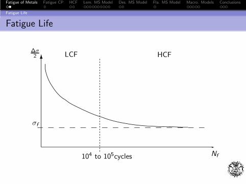
Fatigue Life
Fatigue Life Classification
Types of Fatigue (form in which fatigue occurs): mechanical;thermomechanical; creep; corrosion; rolling contact; fretting;
Fatigue life (duration of the fatigue life):
Low-Cycle Fatigue (LCF) (N < 104 − 105 cycles): stressesare generally high enough to cause appreciable plasticdeformation at the mesoscale (the scale of the RVE) prior tofailure;High-Cycle Fatigue (HCF) (N > 104 − 105 cycles): damageis localized at the microscale as a few micro-cracks and thematerial deforms primarily elastically at the mesoscale up tocrack initiation. The cyclic evolution of an isolated grain canbe resumed by the creation of localized plastic slip bands andthe nucleation of microcracks until the creation of amesocrack.
Fatigue of Metals Fatigue CP HCF Lem. MS Model Des. MS Model Fla. MS Model Macro. Models Conclusions
Fatigue Life
Fatigue Life
LCF HCF∆σ2
σf
Nf104 to 105cycles

Fatigue of Metals Fatigue CP HCF Lem. MS Model Des. MS Model Fla. MS Model Macro. Models Conclusions
Evolution of Fatigue Cracks
Stages
Crack Initiation (CI): is a material surface phenomenon;micro-cracks usually start on localized shear planes at thesurface; once nucleation occurs and cyclic loading continues,the micro-crack tends to grow along the plane of maximumshear stress and through the grain boundary.
Stable Crack Growth (SCG): is normal to the maximumprincipal stress; it depends on the material as a bulk property;
Unstable Crack Growth: leads to ductile or brittle fracture;very short, not important from a practical point of view.
Remark: Under stress amplitudes just above the fatigue limit(HCF), the CI period may cover a large percentage of the fatiguelife; for larger stress amplitudes (LCF), the SCG period can be asubstantial portion of the fatigue life.

Fatigue of Metals Fatigue CP HCF Lem. MS Model Des. MS Model Fla. MS Model Macro. Models Conclusions
High-Cycle Fatigue
Important Features of HCF
HCF of metals may be regarded as a form of materialdegradation/damage caused by cyclic loading;
Damage is controlled by mechanisms at the grain scale(microscale) and, therefore, a description at this scale isnecessary;
At the mesoscale most of the metallic materials can beconsidered isotropic and homogeneous;
Microscopic plasticity should be determined by isotropic andkinematic hardening rules;
Mean stress effect must be taken into account: while meannormal stresses have great effects on failure, mean shearstresses do not.

Fatigue of Metals Fatigue CP HCF Lem. MS Model Des. MS Model Fla. MS Model Macro. Models Conclusions
High-Cycle Fatigue
Important Features of HCF (Cont.)
Macroscopic plasticity is for the most part negligible, andcrack initiation occurs in localized plasticity spots surroundedby a material in elastic range. Damage is localized on amicroscopic scale with negligible influence on the mesoscale⇒ Quasi-Brittle Failures;
Crack initiation modeling is difficult in this fatigue regimesince the scale where the mechanisms operate is not theengineering scale (mesoscale), and local plasticity and damageact simultaneously.
All these features can be well characterized by means of theTheory of Damage Mechanics.

Fatigue of Metals Fatigue CP HCF Lem. MS Model Des. MS Model Fla. MS Model Macro. Models Conclusions
Two-Scale Model
Lemaitre’s Model (1994, 1999, 2005)
It considers a microscopic spherical inclusion with anelasto-plastic-damage behavior embedded in a macroscopicinfinite elastic matrix:
Mesoscale MicroscaleLocalization Law
RVE
INCLUSION
Elastic (E , ν) Elastic (E , ν)Plastic (C , σf )
(σ, ε) Damage (S, s,Dc )
(σµ, ε
µ, ε
µe, ε
µp,D)

Fatigue of Metals Fatigue CP HCF Lem. MS Model Des. MS Model Fla. MS Model Macro. Models Conclusions
Thermodynamics Framework
Free Energy
Free energy of the inclusion: ρϕµ = ρϕµe + ρϕµ
p
Elastic part (affected by the damage variable to model theexperimentally observed coupling between elasticity anddamage)
ρϕµ
e (εµ− ε
µp,D) =1
2(εµ − ε
µp)E(1 − D)(εµ − εµp)
Plastic part (assumes exponential isotropic hardening andlinear kinematic hardening)
ρϕµ
p (α, r) = R∞(rµ +1
be−brµ) +
1
3X∞γαµ : αµ
Free energy of the matrix: ρϕ(ε) = 12εEε

Fatigue of Metals Fatigue CP HCF Lem. MS Model Des. MS Model Fla. MS Model Macro. Models Conclusions
Thermodynamics Framework
State Laws (Inclusion)
Stress Tensor
σµ = ρ
∂ϕµ
∂εµe= E(1− D) : εµe
Isotropic Hardening (it represents the growth in size of theyield surface)
Rµ = ρ∂ϕµ
∂rµ= R∞(1− e−brµ)
Kinematic Hardening (it represents the translation of theyield surface)
Xµ = ρ∂ϕµ
∂αµ=
2
3X∞γαµ
Energy Density Release
Y µ = −ρ∂ϕµ
∂D=
1
2εµe : E : εµe

Fatigue of Metals Fatigue CP HCF Lem. MS Model Des. MS Model Fla. MS Model Macro. Models Conclusions
Thermodynamics Framework
State Laws (Inclusion) (Cont.)
The energy density release can be rewritten as
Y µ =σµ2
eqRµν
2E (1− D)2
with
Rµν =
2
3(1 + ν) + 3(1− 2ν)
(
σµH
σµeq
)2
σµeq =
(
3
2σµD : σµD
)12
, σµH =
1
3tr(σµ), σ
µD = σµ− σµ
H I
The mean stress effect can be taken into account byconsidering a new form of the energy density release ratewhich includes an additional parameter, 0 ≤ h ≤ 1, to modelthe micro-defects closure effect.

Fatigue of Metals Fatigue CP HCF Lem. MS Model Des. MS Model Fla. MS Model Macro. Models Conclusions
Thermodynamics Framework
Dissipation Potential (Inclusion)
Dissipation Potential
Fµ = f µ + Fµx +
S
(s + 1)(1 − D)
(
−Y µ
S
)s+1
Yield Potential
f µ =
(
σµD
1− D− Xµ
)
eq
− Rµ− σ∞
f ≤ 0
Kinematic Hardening Potential
Fµ
x =3
4X∞
Xµ : Xµ

Fatigue of Metals Fatigue CP HCF Lem. MS Model Des. MS Model Fla. MS Model Macro. Models Conclusions
Thermodynamics Framework
Complementary State Laws (Inclusion)
By means of the normality property, the complementary statelaws are obtained as
εµp = λµ ∂F
µ
∂σµ=
3
2
σµD
σµeq
λµ
(1− D)
rµ = −λµ ∂Fµ
∂Rµ= λµ
αµ = −λµ ∂F
µ
∂Xµ = εµp(1− D)− λµ 3
2X∞
Xµ
D = −∂Fµ
∂Y µλµ =
(
−Y µ
S
)s λµ
(1− D)
Remark: The plastic multiplier λµ is derived from the consistencycondition f µ = 0.

Fatigue of Metals Fatigue CP HCF Lem. MS Model Des. MS Model Fla. MS Model Macro. Models Conclusions
Thermodynamics Framework
Damage Evolution and Meso-crack Initiation
The accumulated plastic plastic strain pµ, defined by its rate
pµ = (23 εµp : εµp)
12 , comes out as pµ = λµ/(1− D);
Damage Evolution: energy damage threshold wD
D =
(
−Y µ
S
)s
pµ, if ws > wD
Meso-Crack Initiation: critical damage Dc
D = Dc

Fatigue of Metals Fatigue CP HCF Lem. MS Model Des. MS Model Fla. MS Model Macro. Models Conclusions
Meso/Micro-Scales Linking
Localization Laws
Lin-Taylor Localization Law (adopted by Lemaitre et al.(1990, 1994))
εµ = ε
σµ = σ
Eshelby-Kroner Localization Law (adopted by Lemaitre etal. (1999, 2005))
εµ = ε+ βεµp
σµ = σ − 2G (1− β)εµp
with
β =2
15
4− 5ν
1− ν

Fatigue of Metals Fatigue CP HCF Lem. MS Model Des. MS Model Fla. MS Model Macro. Models Conclusions
Two-Scale Analysis
Application of the Two-Scale Model
Macroscale - Uncoupled Analysis: the meso-quantitiesσ(t), ε(t) are determined from an elastic global structuralcalculation (FEM);
Microscale - Locally Coupled Analysis: the meso-quantitieshistory is used as the input for the post-processing of themicro-quantities by means of the time integration of theconstitutive equations;
First Stage: elasto-plasticity at the microscale with D = 0;Second Stage: for ws = wD ⇒ Damage initiation;Third Stage: for D = Dc ⇒ Meso-crack initiation.
Jump-In Cycles Procedure

Fatigue of Metals Fatigue CP HCF Lem. MS Model Des. MS Model Fla. MS Model Macro. Models Conclusions
Model Limitations
Some Limitations
No plasticity is assumed to occur at the grain scale below themacroscopic fatigue limit, which does not correspond to theexperimental observations, Cugy (2002);
The concept of a scalar variable D used to describe damagecannot be explicitly related to a particular physicalmicromechanism, Monchiet et al. (2006);
The mechanisms of plasticity and damage are assumed to beassociated, which is a relatively strong limitation, Chaboche etal. (2009).
Fatigue of Metals Fatigue CP HCF Lem. MS Model Des. MS Model Fla. MS Model Macro. Models Conclusions
Two-Scale Damage Model
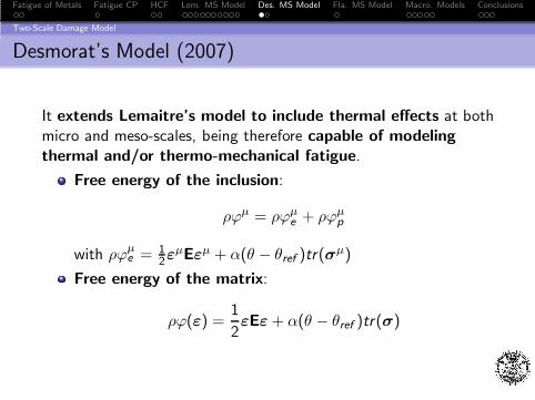
Desmorat’s Model (2007)
It extends Lemaitre’s model to include thermal effects at bothmicro and meso-scales, being therefore capable of modelingthermal and/or thermo-mechanical fatigue.
Free energy of the inclusion:
ρϕµ = ρϕµe + ρϕµ
p
with ρϕµe = 1
2εµEεµ + α(θ − θref )tr(σ
µ)
Free energy of the matrix:
ρϕ(ε) =1
2εEε+ α(θ − θref )tr(σ)

Fatigue of Metals Fatigue CP HCF Lem. MS Model Des. MS Model Fla. MS Model Macro. Models Conclusions
Meso/Micro Scales Linking
Eshelby-Kroner Localization Law
Strains Relation
εµ =
1
1− bD
(
ε+(a − b)D
3(1− aD)tr(ε)I+ b(1− D)εµp
)
+a((1− D)αµ − α)
1− aD(θ − θref )I
with a and b the Eshelby parameters for a spherical inclusiongiven by
a =1 + ν
3(1 − ν), b =
2
15
4− 5ν
1− ν

Fatigue of Metals Fatigue CP HCF Lem. MS Model Des. MS Model Fla. MS Model Macro. Models Conclusions
Flaceliere’s Model (2007)
Main Features
uses two distinct scalar internal variables to account formesocrack propagation (d , β);
considers uncoupled dissipations for plasticity and damage(associative plasticity, non-associative damage);
uses Lin-Taylor localization law to link micro and meso scales;
failure criterion d = dc .

Fatigue of Metals Fatigue CP HCF Lem. MS Model Des. MS Model Fla. MS Model Macro. Models Conclusions
Oller’s Model (2005)
Main Features
Thermo-mechanical elasto-plastic damage model inwhich an internal fatigue variable is included to account forfatigue effects;
Fatigue life predicted using S − N curves of the material.
Free Energy
ϕ = ϕe(Ee ,D, θ) + ϕp(α
p , θ)
= (1−D)1
ρ0EeC0(θ)Ee + ϕp(αp , θ)− θη

Fatigue of Metals Fatigue CP HCF Lem. MS Model Des. MS Model Fla. MS Model Macro. Models Conclusions
Oller’s Model (2005)
Yield and Damage Potentials
Yield Potential
fy = f (S)− K (S, αP)fred (N,Sm,R , θ) = 0
Damage Potential
fD = S(S)− FD(S,D)fred (N,Sm,R , θ) = 0
where f is an uniaxial equivalent stress function, Kfred is astrength threshold, S is an equivalent stress function in the
undamaged space and FDfred is a damage threshold. fred
represents a reduction function.

Fatigue of Metals Fatigue CP HCF Lem. MS Model Des. MS Model Fla. MS Model Macro. Models Conclusions
Oller’s Model (2005)
Reduction Function
The scalar function fred , regarded as an internal variable, isdefined by
fred (N,Sm,R , θ) = fN(N,Sm,R)fθ(θ)
where fN(N,Smax ,R) is the mechanical reduction function,influenced by the number of cycles N, and fθ(θ) is the thermalreduction function. Sm represents the mean stress;
The elastic domain can be modified independently either by athermo-mechanical load or by a reduction factor related to thecumulative degradation of the fatigue strength;
The reduction function is determined from S − N curvesobtained for different stress ratios.
Fatigue of Metals Fatigue CP HCF Lem. MS Model Des. MS Model Fla. MS Model Macro. Models Conclusions
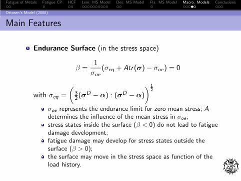
Ottosen’s Model (2008)
Main Features
Endurance Surface (in the stress space)
β =1
σoe(σeq + Atr(σ)− σoe) = 0
with σeq =
(
32(σ
D −α) : (σD −α)
)12
σoe represents the endurance limit for zero mean stress; Adetermines the influence of the mean stress in σoe ;stress states inside the surface (β < 0) do not lead to fatiguedamage development;fatigue damage may develop for stress states outside thesurface (β > 0);the surface may move in the stress space as function of theload history.

Fatigue of Metals Fatigue CP HCF Lem. MS Model Des. MS Model Fla. MS Model Macro. Models Conclusions
Ottosen’s Model (2008)
Evolutions
Back-Stress Tensor Evolution
dα = dβC (σD−α)
Damage Evolution
dD = dβ g(β,D), with g(β ≥ 0,D) ≥ 0
g(β) = KeLβ
Failure Criterion: D = 1

Fatigue of Metals Fatigue CP HCF Lem. MS Model Des. MS Model Fla. MS Model Macro. Models Conclusions
Some Conclusions Regarding HCF Modeling of Metals
Damage and plasticity take place on a scale lower than thescale of the RVE;
Failure can be well characterized by the Theory of DamageMechanics;
Multi-scale models based on the Theory of DamageMechanics are suitable;
A single internal scalar variable might not be enough formesocrack modeling;
Microplasticity should be determined assuming both isotropicand kinematic hardening effects;
Mean stress effect must be considered.

Fatigue of Metals Fatigue CP HCF Lem. MS Model Des. MS Model Fla. MS Model Macro. Models Conclusions
Acknowledgements
Special thanks to Professor Ferdinando Auricchio for giving me theopportunity to work at the Department of Structural Mechanics.

Fatigue of Metals Fatigue CP HCF Lem. MS Model Des. MS Model Fla. MS Model Macro. Models Conclusions
Damage Mechanics-Based Models for High-Cycle
Fatigue Life Prediction of Metals
H.A.F. Argente dos Santos(Postdoc Fellow)
Dipartimento di Meccanica StrutturaleUniversita degli Studi di Pavia
Pavia, December 18th, 2009