Embed Size (px)
Citation preview

F77 T IL i I
DREP-Teclmical'i i¢,f
Sofence Research Centre do recherches Memorandum- 88-25Establishment Pacific pour la d6fense pacifique
Ln
cvRIN
I
A Damage Tolerance Assessment of
Bonded Repairs to CF- 18 Composite Components
Part I: Adhesive Properties
A. J. Russell
DTICELECTEJUL 289 U
December 1988
Research and Development Branch
Department of National Defence
Canada 7 44 100

I l Defence Research Centre de recherchesEstablishment Pacific pour la defense pacifique
DEFENCE RESEARCH ESTABLISHMENT PACIFIC
CFB Esquimalt, FMO Victoria, B.C. VOS IBO
Technical Memorandum 88-25
A DAMAGE TOLERANCE ASSESSMENT OF BONDED REPAIRS TO
CF-18 COMPOSITE COMPONENTS
PART I: ADHESIVE PROPERTIES
BY
A.J. Russell
December 1988
Approved by:
CHIEF
Research and Development Branch
Department of National Defence
Canad'

ABSTRACT
The damage tolerance properties of three epoxy adhesives used in
the manufacture and repair of the composite structure on the CF-18 aircraftare assessed. The resistance to both static fracture and fatigue crack
growth are evaluated. Experimental variables include the mode of fracture
(tension and shear), the fatigue load ratio, the test temperature and the
method of bonding. Both the static and fatigue tests were found to rank the
adhesives in the same order, viz. FM-300K superior to FM-300 superior to EA-
9321. The fatigue testing revealed a tendency for delamination type
failures to occur at low temperature, a situation likely to lead to non-
conservative joint designs. The fatigue crack growth rate data are
explained in terms of the failure mechanisms observed. The implication of
these findings to the selection of repair adhesives for composite aircraft
structure is discussed. -2T A kAf/vrY CA I '/ .
KEY WORDS: Repair, Bonded Joint, Adhesive, Epoxy, Fracture, Fatigue, Crack
Growth, Damage Tolerance, Durability, Composite Materials, Graphite/Epoxy,
Aircraft.
acceSSion For
NTIS GRA&tDTIG TAB
Uannounced 0Justifleatlo
By
DistributiOliAvailablltty Codes
jAail -adorDi't I Speoial
l I I I I II

INTRODUCTION
Adhesive bonding is used extensively in both the manufacture and
repair of composite structure on the CF-18 aircraft. Graphite/epoxy to
titanium bonds are found in the stepped lap joints which attach the wing
skins, horizontal stabilators and vertical stabilizers to the fuselage.
Graphite/epoxy face sheets and closures are bonded to aluminum honeycomb in
numerous components including the rudder, trailing edge flaps and norizontal
stabilators. Adhesively bonded repairs can take various forms including a
single lap joint patch for honeycomb sandwich structure, Figure 1(a), and a
scarf joint configuration for damage to monolithic graphite/epoxy, Figure
1(b).
A well designed adhesive joint should be stronger than the
adjoining structure. This is normally achieved by carrying out an
elastic/plastic stress analysis which is based on the shear stress/shear
strain response of the adhesive. This approach to designing adhesive joints
was developed in part by McDonnell Douglas in the early seventies [1] and
later refined by the US Air Force Primary Adhesively Bonded Structure
Technology (PABST) program [2]. It is not current practice to carry out a
damage tolerance assessment of bonded joints in the design phase although
guidelines to minimize peel stresses are generally followed. This lack of a
damage tolerance qualification of bonded joints arose in part from the PABST
program in which it was concluded that a joint designed to have sufficient
strength would not normally fail in fatigue and that the additional
complexities of a da/dN analysis were not warranted [3].
There are several reasons why the question of damage tolerance of
bonded joints should be re-assessed when looking at bonded repairs to the
CF-18's graphite/epoxy:
- Current CF-18 repair adhesives are more brittle than the 120 0 C curing
toughened epoxy film adhesives that were evaluated in the PABST program.
- In composite material joints the high shear stresses close to the bondline
may result in failure of the composite adherends. Under these conditions,

2
PRE-CURED GRAPHITE/EPOXY PATCH
FILM ADHESIVE
(a) i 1 M 1 , 1
CORE SPLICE
GR/EP PRE-PREG CO-CUREDIN-SITU WITH ADHESIVE
(b)
FILM ADHESIVE MACHINED SURFACE
Figure 1. Examples of adhesively bonded repairs. (a) Surfacepatch bonded to honeycomb sandwich. (b) Scarf repair ofmonolithic laminate.

3
joints designed on the basis of the adhesive properties alone may be non-
conservative.
- Previous fatigue crack propagation studies have not looked at worst case
conditions in terms of both loading mode and environmental effects.
- Repairs are subject to additional constraints such as limitations on the
size and weight of the patch, on changes in the local stiffness and on
perturbation to the airflow. Consequently, the best possible repair may
not have the same degree of strength redundancy as a typical production
joint.
In this report, the growth of cracks between graphite/epoxy
adherends bonded with the CF-1B adhesives will be investigated under both
static and fatigue loading. The principle variables which will be examined
are the test temperature, the fatigue load ratio, R, and the method of joint
fabrication. The resulting data base will be used, in a subsequent report,
to assess the damage tolerance of some typical composite repair schemes. In
addition, future work will also make use of this data base for comparing
other adhesive systems possessing secondary characteristics of special value
in a repair situation.
EXPERIMENTAL
Materials and Fabrication
Table 1 describes the CF-18 adhesives used either in production
or specified in the Structural Repair Manual (SRM). The two film adhesives,
FM-300 and FM-300K differ only in their colour and the type of scrim cloth.
Neither EA-956, which is an unfilled version of EA-9321, nor the foaming
adhesive FM-404 have been included in this test program. The film adhesives
were tested both bonded and co-cured whereas EA-9321 was bonded only,
simulating current practice.

4
TABLE 1
CF-18 Adhesive Materials
Name and Type of adhesive Application Bonding ProcedureSupplier
FM-300 E. .zy film on Gr/Ep face sheets to Secondary bondingAmerican tightly knitted closures and honeycomb 1 hour at 178 0C, 32-Cyanamid scrim cloth, core. 50 psi, vent vacuum.
Repair patch to graphite/ Secondary bondingepoxy H/C sandwich with 4 hours at 149 0C, 20-B-staged adhesive. 29" Hg vacuum.
Scarf joint repair to Gr/ Co-cured with pre-pregEp H/C sandwich. 2 hours at 1780C, 100
psi.
FM-300K Epoxy film on Gr/Ep to titanium step- Co-cured with pre-pregAmerican open knit scrim. lap joints. 2 hours at 178 0C, 100Cyanamid psi.
EA-9321 2 part epoxy with Repair patch to graphite/ Secondary bondingHysol thickener. epoxy skin. 1 hour at 880C, 20-29"
Hg vacuum.
EA-956 2 part epoxy Repair of delaminations. 1 hour at 880C, 20-29"Hysol Hg vacuum.
FM-404 Foaming adhesive Core stabilisation during 1 hour at 178 0C or 4American film. manufacture and at hours at 149 0C.Cyanamid repair splices.

5
Test laminates, of either 24 or 36 unidirectional plies, were
made from Hercules AS4/3501-6 graphite/epoxy and cured according to CF-18
specifications. For co-cured laminates both the top and bottom surfaces were
bled to ensure that the adhesive lay on the mid-plane. Bonded laminates
were fabricated from two 12 or 18 ply laminates. For the initial tests, the
surface of the laminates to be bonded were lightly wet sanded with 600 grit
abrasive paper until drops of water would no longer bead up on the surface.
Later tests examined the effect of more heavily sanding the surface as
detailed below.
Strips of 25 Am thick teflon coated glass fabric were
incorporated into the laminates to act as crack starters. For EA-9321 the
inserts were located at the centre of the bondline but for the filn,
adhesives this was not possible and hence they were positioned adjacent to
one side of the adhesive film. Specimens, 150 mm long by 20 mm wide, were
machined from the laminates and stored in a desiccator until immediately
prior to use. Tests were carried out in laboratory air at -50, 20 and
100'C.
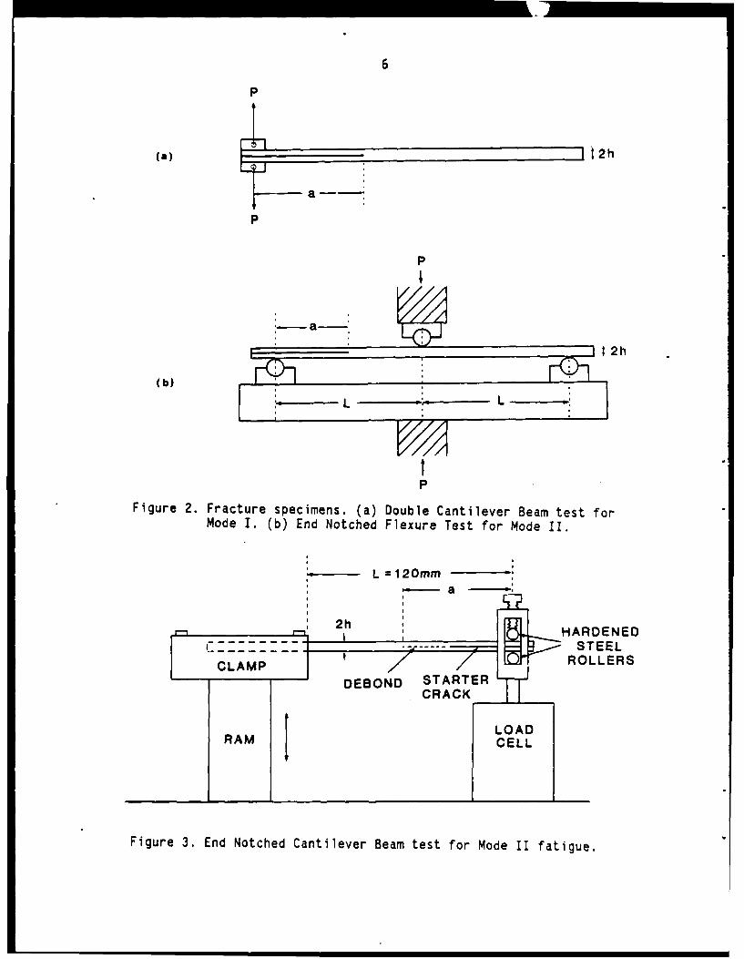
Fracture Testing
Mode I and Mode II adhesive fracture tests were made with Double
Cantilever Beam (DCB) and End Notched Flexure (ENF) specimens respectively.
These specimens, shown in Figure 2, are essentially the same as those used
for previous delamination studies [4] and consequently similar testing
procedures were employed. The ram displacement rate was 10 mm/min for the
DCB tests and 2 mmn/min for the ENF tests.
Fatigue Testing
Cyclic debonding tests under pure shear loading were carried out
on End Notched Cantilever Beam (ENCB) specimens as shown in Figure 3. This
loading arrangement is similar to that used previously to study interlaminar
fatigue crack growth [5]. The span L, was 110 mm, with the debond growing
from ah initial length of 35 mm to a 'inal value of between 100 and 105 mm.
6
P
(a) a I2h
P
P
(b) , -
L -L
PFigure 2. Fracture specimens. (a) Double Cantilever Beam test for
Mode I. (b) End Notched Flexure Test for Mode II.
-L =120mmat
2h1 HARDENED_ __ STEEL
C M ROLLERSDEBOND STA+RTER
CRACK
LOADRAM CELL
Figure 3. End Notched Cantilever Beam test for Mode II fatigue.

7
All tests were run in stroke control on a fully automated MTS load frame
with an 800 N load cell. Blocks of constant amplitude sine-wave cycles were
separated by slow ramp cycles of the same amplitude during which the
specimen compliance was measured. The maximum and minimum values of the
load, P, and load-point displacement, 6, were measured during the last ten
cycles of each block and the average values stored.
Most tests were run at either 2 Hz and an R-ratio of 0 (forward
shear) or at 1 Hz and an R-ratio of -1 (reverse shear). Following
completion of a test the specimen was separated into two halves and the
initial and final crack lengths measured from markings on the fracture
surface.
DATA REDUCTION
Fracture Tests
For the mode I fracture tests the following closed form
expression was used to calculate the mode I fracture energy, GIC [4],
3CP¢ 2
2ab (1)
where C is the loading compliance of the specimenPc is the load at fracturea is the crack length
and b is the specimen width.
The equation for calculating the mode II fracture energy, GII c for the ENF
specimen was modified to take into account the presence of the adhesive [6].
9p2aa2C
2b(2L 3 + 3aa3 )
where a = 1+4t/(h-t)t is the adhesive thickness
and h is the specimen half thickness.

8
Fatigue Tests
The crack length corresponding to each compliance measurement was
calculated from Equation 3,
C= Cf(a 3 - ai 3) Ci(af3 - a3 )a 3 - ai3
where a is the crack lengthC is the compliance
and i and f refer to the initial and final values respectively,
and the strain energy release rate, Gil, calculated from Equation 4,
3(Ci - Cf)a 2p2= 2b(ai3 - at) (4)
where, P is the load.
Next, the crack growth rate, da/dN, corresponding to each crack
length was determined by least squares fitting a third order polynomial to
the crack length, a, versus number of cycles, N, data. For each specimen,
Gil increased initially due to the increasing crack length, then reached a
maximum at a/L t 0.6 after which it declined due to the decreasing load.
Thus each specimen gave two values of da/dN over a limited range of G
values. Several specimens tested at different constant amplitudes were
required to produce a log da/dN versus log AGII plot covering 3 or 4 decades
of crack growth rate. For all plots AGII = GmCx - Gmin and for both R=O and
R=-1, Gmox corresponds to Pmox and Gmin corresponds to zero load following
the convention adopted by reference 5.
RESULTS
Fracture Tests
In Figures 4-6 an example is shown of the mode I load-
displacement (P-6) curves for each adhesive at each test temperature. All
materials displayed linear behaviour up to the initiation of crack growth

9
200 FM-300K
160C
140
'-120z(.
.100,
0
40 -0C
20
0 5 10 15 20 25 30
OISPLACEMENT, 6 (mm)
Figure 4. Examples of P-6 curves for Mode I fracture of FM-300Kat different test temperatures.
100 I I
eo~- FM-300
100 C
so -4
6 sot-10-
303r
o510 15 20 25 30 3DISPLACEMENr. a (mm)
Figure 5. Examples of P-6 curves for Mode I fracture of FM-300 atdifferent test temperatures.

10
70 F
CA-032 1
60
so-220.
00 t
0 5 10 1520 25 3
DISPLACEMENT, 6(mm)
Figure 6. Examples of P-5 curves for Mode I fracture of EA-9321at different test temperatures.

11
followed by varying degrees of slip/stick crack propagation at low
temperatures and stable crack growth at higher temperatures. The general
shape of the P-6 plots for FM-300K and EA-9321 indicates that the fracture
energy remained relatively constant as the debond extended. However, in the
FM-300 specimens the fracture energy was found to increase as evidenced by
the plateau like nature of the P-6 curves. This increase was due to the
stretching of the scrim cloth between the fracture surfaces behind the crack
tip as it failed to separate cleanly from the epoxy.
In Figure 7 the mode I fracture energies are plotted as a
function of temperature for all three adhesives. The values given for FM-
300 correspond to the initial (or minimum) fracture energy only, whereas the
results for the other two adhesives are averaged over the total length of
debond extension. Where slip/stick (or initiation/arrest) behaviour was
observed, the values shown correspond to crack initiation. All failures
were cohesive within the adhesive itself and no difference was observed
between bonded and co-cured specimens.
Figures 8-11 show the corresponding results for mode II fracture.
All of the P-6 curves showed a significant amount of non-linear behaviour
prior to fracture with the exception of the EA-9321 at -500C. At 100 0C none
of the curves was sufficiently linear to allow the use of linear elastic
fracture mechanics to calculate GIIc. Fracture energies are given in Figure
11 where appropriate, otherwise an estimate of the work of fracture [7] s
given instead. No rigorous non-linear treatment of the P-6 curves wa;
undertaken for reasons that will be discussed below. All fracture surfaces
indicated cohesive failure modes and once again there was no difference
between bonded and co-cured specimens.
Fatigue Tests
Most of the fatigue tests were carried out on FM-300K and EA-9321
adhesives with only limited testing of FM-300. This was because of the
history dependent behaviour caused by the partial debonding of the FM-300
scrim cloth as described below.

12
2.0r
E
LU
Z0 -
w
U
U-
w0.5 EA-9321
0
0-50 0 50 100
TEMPERATUREC(C)
Figure 7. Effect of temperature on the Mode I adhesive fractureenergy.

13
2.5 -
FM-300K ,2 C
2.0 -
Q 1.5 -
0
1.0
5.0 -
0.0 I0.0 1.0 2.0 3.0 4.0 5.0
DISPLACEMENT, (mm)
Figure 8. Examples of P-6 curves for Mode II fracture of FM-300Kat different test temperatures.
2.5
FM-300
2.0
1.5 - -50 C 1000 C
002 0
1.0
5.0 -
0.0 1 __I
0.0 1.0 2.0 3.0 4.0 5.0
DISPLACEMENT, 6 (mm)Figure 9. Examples of P-6 curves for Mode II fracture of FM-300
at different test temperatures.

14
2.5
EA-93212.0
200 C
1.5 0 C
0
-j1.0
5.0 - 50
0.00.0 1.0 2.0 3.0 4.0 5.0
DISPLACEMENT, 8 (mm)
Figure 10. Examples of P-6 curves for Mode II fracture of EA-9321at different test temperatures.

15
4.0
w3.0-
FM-300
U.
IL
0
r2.0-0
0
wuz
W1.0-W
0a WORK OFU- FRACTURE
01-50 0 50 100
TEMPERATURE (CC)
Figure 11. Effect of temperature on the Mode II adhesive fractureenergy or work of fracture.

16
Effect of Frequency
The sensitivity of the cyclic debonding behaviour to test
frequency was investigated over the range 0.1 to 4 Hz. These tests were run
on co-cured FM-300K specimens at 100 0C and R = -1 as it was felt that these
would best reveal evidence of any strain rate sensitivity. The results
plotted in Figure 12 indicate that there was no significant frequency
effect.
Effect of Temperature
Figures 13 and 14 show the effect of temperature on FM-300K and
EA-9321 for R=-1. Raising the temperature increased the fatigue crack
growth rates in both the co-cured FM-300K specimens and the bonded EA-9321
specimens. However, the situation was more complex in the bonded FM-300K
samples where the failure path moved from the adhesive at elevated
temperatures to the composite matrix at low temperatures [6]. At 200C both
failure modes were observed, with a transition from one mode to the other
occurring between 0.2 and 0.4 kJ/m 2. Comparing Figures 13 (a) and (b)
reveals that failure through the epoxy matrix on the surface of the
adherends has led to a substantial reduction in the AG values required for
fatigue crack growth at -500C. As a result of this finding additional tests
were undertaken to ascertain the effect of removing the surface matrix layer
on the composite adherends prior to bonding. An examination of the EA-9321
specimens tested at -500C revealed that at low AG values they too had failed
via surface matrix layer cracking.
Effect of Removing Surface Matrix Layer
Two different sanding procedures were investigated in determining
the effect of removing the surface matrix layer in the FM-300K specimens.
The first involved wet sanding with successively finer and finer grits
finishing with a 600 grit paper until all damage from the coarser grits had
been removed. The second method was similar to that used for preparing
scarf joint repairs at the Naval Air Rework Facility (NARF). A belt sander

17
-2
0 0.1 Hz
E A 1.0 Hz% o 4.0 Hz
z
x 1 0 3
uJ FM-300K1000C
4I-
U. 10
0.1 0.2 0.4 0.6 1.0
AG (kJ/m 2 )
Figure 12. Effect of frequency on the fatigue crack growth rateof FM-300K at 1000.
0== m=R m= mn

18
BONDED FM-300K CO-CURED FM-300K
A
-f2 - 0
zAA
A .A1.A
Ui A
* A
f-3 F A
* A
00 A
xU
LUU
* 10100
A a 20CA -50 0 C
0.1 0.2 0.4 0.6 1.0 0.2 0.4 0.6 1.0 2.0AG (kJ/M 2) AG (kJ/ M2 )
Figure 13. Effect of temperature on the fatigue crack growth rateof FM-300K.

19
0- 1
• 1000C
* 20 0 C
s -500C
Q 10o .S
E
E A
z0
I ILdfI--U< -3
z .
0U
<A
A
tL.
0
A
A
C..) AA
A
A BONDED
A
R-1, f lH z
.01 .02 .04 .06 0.1 0.2 0.4 0.6 1.0AG (kJ/m 2)
Figure 14. Effect of temperature on the fatigue crack growth rateof EA-9321.

20
with an 80 grit paper was used to obtain the desired amount of surface
removal finishing with a wipe from a dry cloth to remove any excess dust.
Figure 15 indicates that both methods resulted in a significant
shift in the da/dN versus AG curves to higher AG values although neitherprocedure was able to achieve the superior fatigue resistance of the co-
cured joints. The wet sanding was slightly superior at higher AG values asreflected in the fracture surfaces which showed fewer broken fibres on the
adhesive face, indicative of less delamination.
Effect of R-ratio
The enhanced fatigue crack growth rates due to shear reversal
(R=-1) are compared with the da/dN values for positive shear only (R=O) inFigure 16. The curves for EA-9321 and co-cured FM-300K at 100 0C display a
greater effect of R-ratio than either of the -500C tests shown.
Comparison of FM-300 with FM-300K
Figures 17 (a) and (b) show the da/dN versus AG curves for
several FM-300 specimens at 200C and 1000C. Unlike the data for FM-300K and
EA-9321 the data points for the individual specimens do not fall back on top
of themselves as AG increases to a maximum and then diminishes. Instead, as
the debond grows, the resistance to fatigue crack growth increases resulting
in the type of da/dN versus AG curves shown. Because of this historydependent behaviour only a limited number of tests were run on the FM-300specimens. When compared with the corresponding results for FM-300K (dashed
curves in Figure 17) it is apparent that fatigue crack growth initiates in
the FM-300 specimens at significantly lower AG values.
DISCUSSION
The results of both the mode I and mode II static tests as well
as the mode II fatigue tests rank the adhesives in the same order, i.e. FM-
300K is better than FM-300 which is better than EA-9321. The superior

2110 - 1 , ,,, , , ,
LIGHT SANDING
o 80 GRIT DRY
o 600 GRIT WET /7I7
ACO-CURED
1-2
100
Z 1 -3
* /7
V
10
.0 .0 O. V . . . . .
-5C
Figure 15. Effect of bonding procedure on the fatigue crack
growth rate of FM-300K at -500C.
0

22
00
0-2 0~
10 800
0 9
-5 * !
"E 0o ko
S0 3 0 0
,00 10
Ld BODE
*v 0
-4
0
vis 0 oE-3110'
t CO-CURED
SFM-300K -50 C
CO-CURED
.01 .02 .04 .06 0.1 0.2 0.4 0.6 1.0 2.0
-aG (k J/m 2)
Figure 16. Effect of R-ratio on the fatigue crack growth rate of FM-300K and EA-9321. Open symbols: R=0. Solid symbols: R--1.
0 I II

23
1 -1 I "i I 1 i I___________________ I [ i i ________________i____i____I_
20 0 C 100"C
* TEST 1 0 TEST 1m TEST 2 s TEST 2A TEST 3
10
I /I
S, I
E/
E
I- IIn - I IF
,0 I
0
I- F-3/
I
D IAA
A FM-300
AA R=-1, f~1Hz
.06 0.1 0.2 0.4 0.6 1.0 0.1 0.2 0.4 0.6 1.0AG (kJ/m 2) AG (kJ/m 2 )
Figure 17. Comparison of fatigue data for co-cured FM-300 at 200Cand 100 0C with FM-300K curves (dashed lines). Arrowsindicate direction of test progression.

24
performance of the two film adhesives was expected and is a direct
consequence of their greater rubber content. The reduced performance of FM-
300 compared with FM-300K was not anticipated although a similar
deteriorating effect of a closed knit scrim cloth has been observed for FM-
1000 type adhesives [8]. The thicker scrim in FM-300 was dictated by the
need to prevent electrical contact between graphite fibres and aluminum
honeycomb, a situation likely to lead to galvanic corrosion of the core.
Based on the present results, it would appear that the use of FM-300K would
be preferable to FM-300 except when bonding to aluminum core. This would
include the scarf repair in Figure 1(b) as well as the patch-to-skin part of
the repair in Figure 1(a). However, in some situations the greater flow of
the FM-300 (greater initial thickness but similar cured thickness) is
beneficial as it is more forgiving of two poorly fitting surfaces. The use
of two layers of FM-300K film in such circumstances might be worthy of
future investigation.
The P-3 curves indicated that all three adhesives behaved in a
more brittle manner as the temperature was lowered to -500C although this
did not always correspond to the minimum fracture energy or work of
fracture. The reason for this is that while all the adhesives showed
greater ductility at elevated temperature their ability to sustain high
shear stresses is also reduced and in energy terms this may override the
increased strain to failure. In contrast, the fatigue crack growth rate was
greatest at elevated temperatures. The only exception was in the case of
the bonded FM-300K specimens where cracking occurred in the surface matrix
layer of the graphite/epoxy adherends at low temperature. Not only was this
the worst case condition for fatigue growth, the change in failure mode
means that design methodologies based on adhesive properties alone will be
non-conservative. Failures of adhesively bonded composite joints by
delamination have generally been attributed to peel stresses [9]. However,
the present results show that shear stresses alone can cause "interlaminar"
failure.
For all three adhesives, fatigue crack growth occurred at AG
values substantially below G11C. A fatigue threshold, AGth has been defined
as the strain energy release rate below which no fatigue growth occurs [10].

25
No special effort was made to measure AGth in this investigation. However,
approximate values can be estimated by extrapolating the da/dN versus AG
curves down to 10-6 mm/cycle. Some of these values for the R=-1 tests are
shown as a percentage of GII ¢ in Figure 18 and indicate that fatigue
cracking can occur at AG values as low as 1% of the fracture energy.
Ideally, a damage tolerant repair (in addition to being stronger
than the surrounding structure) should be designed in such a manner that no
fatigue growth would occur even with a debond type flaw present. Under
these conditions the fracture energy of the adhesive would not be a factor
in the design. For this reason, no non-linear analysis of the adhesive
fracture behaviour was pursued in this investigation. The consequences of a"no growth" design methodology on some typical composite repair schemes will
be analysed in part 2 of this report.
CONCLUSIONS
(1) The film adhesives FM-300 and FM-300K are substantially more damage
tolerant than the paste adhesive EA-9321 because of the greater
ductility imparted by their higher rubber content. This is especially
true at elevated temperature.
(2) FM-300 is less damage tolerant than FM-300K due to the close knit scrim
cloth debonding from the adhesive.
(3) Joints formed by secondary bonding are less durable than co-cured joints
due to the presence in the former of a relatively less fatigue resistant
matrix layer adjacent to the bond line.
(4) Removal of the surface matrix layer of the composite prior to bonding
can raise the threshold for fatigue growth at low temperatures by as
much as a factor of two.
(5) Shear reversal (R=-1) increases the sensitivity to fatigue crack growth
compared to forward shear (R=O) alone. This is especially true at
elevated temperature.

26
8.0
7.0
FM-300K CO-CURED6.0
5.0
4EA-93214.0-
3.0FM-300K BONDED
2.0-
1.0 -
0-50 0 50 100
TEMPERATURE (0C)
Figure 18. Fatigue thresholds normalized with respect to fractureenergy as a function of temperature for FM-300K andEA-9321.

27
(6) Thresholds for fatigue crack growth are typically between I and 10
percent of GII c for R=-1, indicating a strong sensitivity to fatigue
loading.
ACKNOWLEDGEMENTS
The support and encouragement of Dr. K. N. Street as well as the
skilled technical assistance of E. Jensen are both gratefully acknowledged.
REFERENCES
1. L.J. Hart-Smith, "Analysis and Design of Advanced Composite BondedJoints", Douglas Aircraft Company, NASA CR-2218, Jan. 1973.
2. L.J. Hart-Smith, "Adhesive-Bonding of Aircraft Primary Structure",Douglas Aircraft Company, MDC Paper 6979, 1980.
3. L.J. Hart-Smith, "Design and Analysis of Bonded Repairs for MetalAircraft Structures", Douglas Aircraft Company, Douglas Paper 7089,1981.
4. A.J. Russell and K.N. Street, "Moisture and Temperature Effects on theMixed-Mode Delamination Fracture of Unidirectional Graphite/Epoxy" STP876 on Delamination and Debondinq, ASTM, Philadelphia, 1985, pp 349-370.
5. A.J. Russell and K.N. Street, "The Effect of Matrix Toughness onDelamination", STP 937 on Toughened Composites, ASTM, Philadelphia,1987, pp 275-294.
6. A.J. Russell, "Fatigue Crack Growth in Adhesively Bonded Graphite/EpoxyJoints",Proc. ASME Symposium on Advances in Adhesively Bonded Joints,Chicago, 1988.
7. A.J. Russell, "On the Measurement of Mode II Interlaminar FractureEnergies", DREP Materials Report 82-0, Dec. 1982.
8. D.M. Brewis, J. Comyn, B.C. Cope and A.C. Moloney, "Effect of Carrierson the Performance of Aluminum Alloy Joints Bonded with an Epoxide-Polyamide Adhesive", Polymer, 21, 1980, pp 344-351.
9. L.J. Hart-Smith, "Adhesively Bonded Joints for Fibrous CompositeStructures", Douglas Aircraft Company, Douglas Paper 7740, 1986.
10. W.S. Johnson and S. Mall, "A Fracture Mechanics Approach for DesigningAdhesively Bonded Joints", STP 876 on Delamination and Debonding, ASTM,Philadelphia, 1985, pp 189-200.

DISTRIBUTION
REPORT NUMBER: DREP Technical Memorandum 88- 25
TITLE: A Damage Tolerance Assessment of BondedRepairs to CF-18 Composite Components.Part I: Adhesive Properties
AUTHOR: A. J. Russell
DATED: December 1988
SECURITY GRADING: UNCLASSIFIED
2 - DSIS BRITAIN
1 - CRAD 1 - DRIC1 - C/DREA1 - C/DREV1 - C/DRES UNITED STATES1 - DRDA1 - DRDL 1- DTIC1 - DRDM1 - CDLS (W)I - CDLS (L)1 - DRA (P)
1 - DAS Eng 61 - DAS Eng 6-31 - DAS Eng 31 - DFTEM 21 - PMO NSA (SEM)1 - QETEI - AETE1 - AMDU (MPB)I - NRC/NAE1 - Canadair

UNCLASSIFIEDSECURITY CLASSIFICATION OF FORM
(highest classification of Title, Abstract, Keywords)
DOCUMENT CONTROL DATA(Security classification of title, body of abstract and indexing annotation must be entered when the overall document is classified)
1. ORIGINATOR (the name and address of the organization preparing the document 2. SECURITY CLASSIFICATIONOrganizations for whom the document was prepared. e.g. Establishment sponsoring (overall security classification of the documenta contractor's report, or tasking agency. are entered in section B.) including special warning terms if applica~le)
Defence Research Establishment PacificFMO Victoria, BC UNCLASSIFIEDVOS IBO
3. TITLE (the complete document title as indicated on the title page. Its. classification should be indicated by the appropriateabbreviation (S.C.R or U) in parentheses after the title.)
A Damage Tolerance Assessment of Bonded Repairs to CF-18 Composite Components.Part I: Adhesive Properties
4. AUTHORS (Last name, first name, middle initial. If military, Show rank, e.g. Doe, Maj. John E.)
Russell, Alan J.
5. DATE OF PUBLICATION (month and year of publication of 6a. NO. OF PAGES (total 6b. NO. OF REFS (total cited indocument) containing information. Include document)
Annexes. Appendices. etc.)December 1988 27 10
7. DESCRIPTIVE NOTES (the category of the document, e.g. technical report, technical note or memorandum. If appropriate, enter the type ofreport, e.g. interim, progress, summary, annual or final. Give the inclusive dates when a specific reporting period is covered.)
DREP Technical Memorandum
S. SPONSORING ACTIVITY (the name of the department project office or laboratory sponsoring the research and development Include theaddress.)
DREP
9& PROJECT OR GRANT NO. (if appropriate, the applicable research 9b. CONTRACT NO. (if appropriate, the applicable number underand development project or grant number under which the document which the document was written)was written. Please specify whether project or grant)
10a ORIGINATOR'S DOCUMENT NUMBER (the official document 10b. OTHER DOCUMENT NOS. (Any other numbers which maynumber by which the document is identified by the originating be assigned this document either by the originator or by theactivity. This number must be unique to this document) sponsor)
DREP TM 88-25
11. DOCUMENT AVAILABILITY (any limitations on further dissemination of the document, other than those imposed by security classification)
(X) Unlimited distributionDistribution limited to defence departments and defence contractors; further distribution only as approvedDistribution limited to defence departments and Canadian defence contractors; further distribution only as approvedDistribution limited to government departments and agencies; further distribution only as approvedDistribution limited to defence departments; further distribution only as approvedOther (please specify):
12. DOCUMENT ANNOUNCEMENT (any limitation to the bibliographic announcement of this document This will normally correspond tothe Document Availabilty (11). However, where further distribution (beyond the audience specified in 11) is possible, a widerannouncement audience may be selected.)
UNCLASSIFIED
SECURITY CLASSIFICATION OF FORM
oC003 9/ 04/7

UNCLASSIFIEDSECURITY CLASSIFICATION OF FORM
13. ABSTRACT ( a brief and factual summary of the document It may also appear elsewhere in the body of the document itself. It is highlydesirable that the abstract of classified documents be unclassified. Each paragraph of the abstract shall begin with an indication of thesecurity classification of the information in the paragraph (unless the document itself is unclassified) represented as (S), (C), (R). or (U).It is not necessary to include here abstracts in both official languages unless the text is bilingual).
The damage tolerance behaviour of three epoxy adhesives used in
the manufacture and repair of the composite structure on the CF-18 aircraft
is assessed. The resistance to both static fracture and fatigue crack
growth are evaluated. Experimental variables include the mode of fracture
(tension and shear), the fatigue load ratio, the test temperature and the
method of bonding. Both the static and fatigue tests were found to rank the
adhesives in the same order, viz. FM-300K superior to FM-300 superior to EA-
9321. The fatigue testing revealed a tendency for delamination type
failures to occur at low temperature, a situation likely to lead to non-
conservative joint designs. The results are discussed in terms of the
failure mechanisms observed and the implication of these findings to the
selection of repair adhesives for composite aircraft structure is discussed.
14. KEYWORDS. DESCRIPTORS or IDENTIFIERS (technically meaningful terms or short phrases that characterize a document and could behelpful in cataloguing the document They should be selected so that no security classification is required. Identifiers, such as equipmentmodel designation, trade name, military project code name, geographic location may also be included. If possible, keywords should be selectedfrom a published thesaurus. e.g. Thesaurus of Engineering and Scientific Terms (TEST) and that thesaurus identified. If it is not possible toselect indexing terms which are Unclassified, the classification of each should be indicated as with the title.)
repair
bonded joint
adhesive
epoxy
fracture
fatigue
crack growth
damage tolerance
durability
composite materials
graphite/epoxy
aircraft
UNCLASSIFIED
SECURITY CLASSIFICATION OF FORM