Embed Size (px)
Citation preview
Dan Dugan Sound Design
Models E-1 and E-1A
Automatic Mixing Controllers
User GuideRelease Date: August 2013
Version: 3.2
Author: Rob Wenig
Important Safety Instructions and WarningsThe Model E-1A’s circuitry is made in the USA and meets applicable national safety stan-dards.
Standards Compliance
The third-party power supply provided with this product has been certified to complywith UL.
Safety Instructions
1. Read these instructions.
2. Keep these instructions.
3. Heed all warnings.
4. Follow all instructions.
5. Do not use this apparatus near water.
6. WARNING! To reduce the risk of fire or electric shock, do not expose this appa-ratus to rain or moisture.
7. Clean only with dry cloth.
8. Do not block any ventilation openings. Install in accordance with the manufac-turer’s instructions.
9. Do not install near any heat sources such as radiators, heat registers, stoves, orother apparatus (including amplifiers) that produce heat.
10. Do not defeat the safety purpose of the polarized or grounding-type plug. A po-larized plug has two blades with one wider than the other. A grounding type plughas two blades and a third grounding prong. The wide blade or the third prongare provided for your safety. If the provided plug does not fit into your outlet,consult an electrician for replacement of the obsolete outlet.
11. Protect the power cord from being walked on or pinched particularly at plugs,convenience receptacles, and the point where they exit from the apparatus.
12. Only use attachments/accessories specified by the manufacturer.
13. Unplug this apparatus during lightning storms or when unused for long periodsof time.
14. WARNING! Refer all servicing to qualified service personnel. Servicing is re-quired when the apparatus has been damaged in any way, such as power-supplycord or plug is damaged, liquid has been spilled or objects have fallen into the ap-paratus, the apparatus has been exposed to rain or moisture, does not operatenormally, or has been dropped.
15. WARNING! To reduce the risk of electric shock, DO NOT REMOVE COVER. Nouser serviceable parts inside.
Warranty StatementWarranty: One year parts and labor
Dan Dugan Sound Design warrants that Model E-1A hardware will be free from de-fects in components and workmanship for a period of 12 months from the date of in-voice. During the warranty period, Dan Dugan Sound Design will cover the cost of allparts and labor to remedy the defect, or replace products which prove to be defective.Dan Dugan Sound Design is not obliged to honor this warranty if the hardware hasfailed to be maintained and operated as specified by Dan Dugan Sound Design, in theaccompanying documentation, or other than in accordance with industry standards.Defects caused by unauthorized modifications, misuse, negligence, act of God or ac-cident are not covered by this warranty. Software is provided as a convenience, butdue to the wide variety of computer systems, cannot be guaranteed to work. ThisLimited Warranty is exclusive and no other warranty is expressed or implied. Dan Du-gan Sound Design does not warrant that Dan Dugan Sound Design software, or anythird-party software, is error free. Third party branded or manufactured goods aresupplied by Dan Dugan Sound Design with care but without responsibility andsubject only to third party suppliers’ warranties. In all other respects Dan DuganSound Design is not liable for consequential damages.

Dugan Models E-1 and E-1A User Guide
Table of Contents
Chapter 1: Introduction ............................................................................................. 7
Theory of Operation ................................................................................... 7
Remote Control and Software............................................................... 9
Model E-1 vs. E-1A ..................................................................................... 9
Chapter 2: Quickstart ............................................................................................... 11
Connections ................................................................................................ 11
Analog I/O ............................................................................................ 11
Digital I/O ............................................................................................. 12
Power-up Reset Command................................................................... 12
Linking Multiple Dugans ........................................................................ 13
Operation ..................................................................................................... 14
Chapter 3: Installation and Configuration.................................................. 15
Installation .................................................................................................. 15
Rack Mounting ..................................................................................... 15
Power Supply........................................................................................ 16
Audio Wiring ......................................................................................... 16
Signal Levels ........................................................................................ 19
Linking Multiple Dugans ..................................................................... 19
Configuration.............................................................................................. 20
Power-up Commands .......................................................................... 20
Connecting to a Computer.................................................................. 22
5
Dugan Models E-1 and E-1A User Guide
Chapter 4: Dugan Control Panel ....................................................................... 29
The Top Pane ............................................................................................. 30
Setting Controls and Naming Units/Channels .............................. 31
Setting Controls ................................................................................... 31
Naming Units and Channels ............................................................... 31
Channel Pane ............................................................................................ 32
Level Indicator...................................................................................... 32
Bypass................................................................................................... 33
Channel Modes .................................................................................... 33
Preset .................................................................................................... 34
Channel Groups.................................................................................... 35
Override................................................................................................. 35
Meters ................................................................................................... 36
Weight Controls ................................................................................... 36
Master Pane ............................................................................................... 39
Indicators .............................................................................................. 39
Controls................................................................................................. 40
Chapter 5: Standalone Hardware Operation............................................. 43
Settings ........................................................................................................ 43
Muting Channels on a Pre-fader Insert ............................................ 45
Pre-listening to Muted Channels Using a Post-fader Insert ............ 46
Chapter 6: Updates..................................................................................................... 47
Appendix A: Specifications .................................................................................... 49
Appendix B: Connector Pinouts .......................................................................... 51
6
Dugan Models E-1 and E-1A User Guide
Chapter 1: Introduction
The Model E-1A Automatic Mixing Controller helps professional audio engineershandle multiple live mics without continually riding individual faders. This multi-channel audio signal processor patches into the channel insert points of a mixingconsole. The Model E-1 detects which mics are being used, and makes fast, transpar-ent crossfades. This eliminates late upcuts, reduces system noise and feedback, andlets the engineer focus on balance and sound quality. The Model E-1A has both ana-log and digital I/O connectors.
The Model E-1A enhances a diverse group of live applications that require multiplemics:
• Conference reinforcement, video trucks
• Houses of worship
• Film and television dialogue, reality shows
• Theater
• Boardrooms, civic meetings, community TV
• Teleconferencing and distance learning
Several features expand the Model E-1A’s capabilities:
• 16-channel mode (option for digital interface only)
• Dugan Control Panel software offers additional controls
• Linking allows up to eight Dugan units to work as one large automatic mixer
Theory of OperationThe Dugan Model E-1A Automatic Mixing Controller uses the Dugan Speech System™,a patented and trademarked automatic mixing function. This results in a naturalone-mic ambience with minimal noise or feedback. The Dugan Speech System doesnot limit, compress, or control levels. It performs just one critical function: cuing mul-tiple live mics in situations with unpredictable dialogue. It is essential to distinguishthis behavior from the distracting fluctuation of levels and uneven ambience pro-duced by a conventional noise gate.
7
Dugan Models E-1 and E-1A User Guide
When one person talks at a time, the Dugan Speech System rapidly fades that mic’sgain up and the others down. When the speaker pauses, that mic fades down and theothers up, so the gain of all mics sums to equal that of one mic at full gain. Whenthe next person talks, the system fades that mic’s gain up and the others down. Theresult sounds like passing one mic among several speakers.
When multiple people talk at once, the gain is shared among active mics. All micssound normal when used but there is no change in ambience, noise buildup, or feed-back.
While people are talking, use the console’s faders to set appropriate relative levels foreach mic channel. You can leave the faders up when the mics are not used becausethe Dugan Speech System cues the mics up when needed.
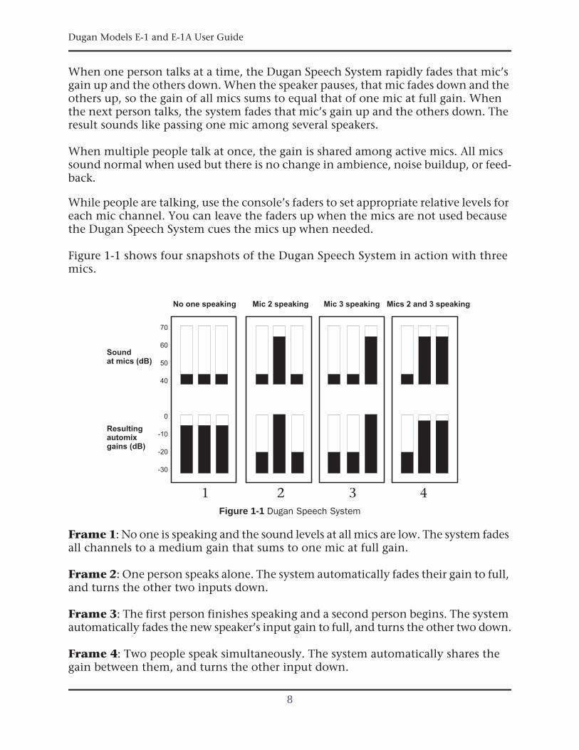
Figure 1-1 shows four snapshots of the Dugan Speech System in action with threemics.
Figure 1-1 Dugan Speech System
Frame 1: No one is speaking and the sound levels at all mics are low. The system fadesall channels to a medium gain that sums to one mic at full gain.
Frame 2: One person speaks alone. The system automatically fades their gain to full,and turns the other two inputs down.
Frame 3: The first person finishes speaking and a second person begins. The systemautomatically fades the new speaker’s input gain to full, and turns the other two down.
Frame 4: Two people speak simultaneously. The system automatically shares thegain between them, and turns the other input down.
Sound
No one speaking Mic 2 speaking Mic 3 speaking Mics 2 and 3 speaking
at mics (dB)
40
50
60
70
Resultingautomixgains (dB)
-30
-20
-10
0
1 2 3 4
8
Dugan Models E-1 and E-1A User Guide Introduction
Remote Control and SoftwareTwo Java applets are provided on a thumb drive or CD, or can be downloaded fromour website:
• The Dugan Control Panel offers expanded operational capabilities (see Chapter 4:Dugan Control Panel).
• The Dugan Utility helps you connect to a network and update the firmware (seeChapter 6: Updates).
The Model E-1A can be controlled three ways:
• Front panel
• Dugan Control Panel
• ASCII commands via Ethernet (contact Dan for information)
Subscribe to the duganusers Yahoo group to be notified when updates are available.
Model E-1 vs. E-1AFor serial numbers 417 and above, the Model E-1 is now called Model E-1A. Model E-1scan use the latest software as described in this manual. However, only the Model E-1Aprovides the following additional features:
• Eight and sixteen channel modes
• Groups a, b, and c
• Input and output level meters
• Locking power connector
9

Dugan Models E-1 and E-1A User Guide
10
Dugan Models E-1 and E-1A User Guide
Chapter 2: Quickstart
This section provides step-by-step instructions to help you get started quickly. It in-cludes information to connect and install the Model E-1A, make initial settings, andlink units.
Connections1. Connect the provided power supply to the Model E-1A.
2. Set the NORM-SLAVE switch on the rear panel to NORM (up) for normal (not linked)operation.
The Model E-1A can be interfaced with an analog or digital console using analogor digital connections.
Analog I/O
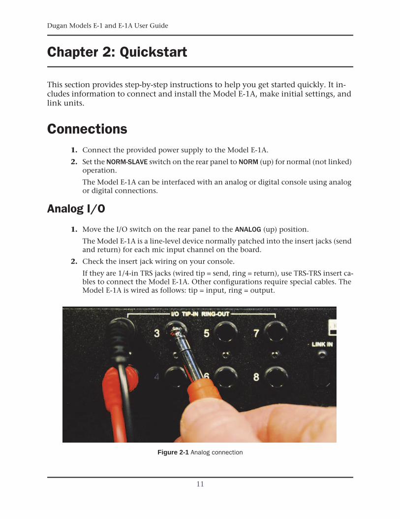
1. Move the I/O switch on the rear panel to the ANALOG (up) position.
The Model E-1A is a line-level device normally patched into the insert jacks (sendand return) for each mic input channel on the board.
2. Check the insert jack wiring on your console.
If they are 1/4-in TRS jacks (wired tip = send, ring = return), use TRS-TRS insert ca-bles to connect the Model E-1A. Other configurations require special cables. TheModel E-1A is wired as follows: tip = input, ring = output.
Figure 2-1 Analog connection
11
Dugan Models E-1 and E-1A User Guide
Digital I/O
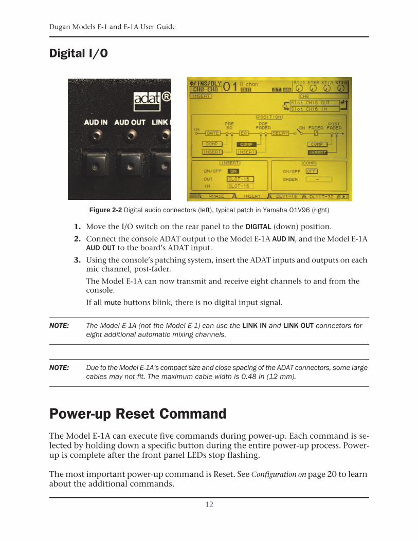
Figure 2-2 Digital audio connectors (left), typical patch in Yamaha O1V96 (right)
1. Move the I/O switch on the rear panel to the DIGITAL (down) position.
2. Connect the console ADAT output to the Model E-1A AUD IN, and the Model E-1AAUD OUT to the board’s ADAT input.
3. Using the console’s patching system, insert the ADAT inputs and outputs on eachmic channel, post-fader.
The Model E-1A can now transmit and receive eight channels to and from theconsole.
If all mute buttons blink, there is no digital input signal.
NOTE: The Model E-1A (not the Model E-1) can use the LINK IN and LINK OUT connectors foreight additional automatic mixing channels.
NOTE: Due to the Model E-1A’s compact size and close spacing of the ADAT connectors, some largecables may not fit. The maximum cable width is 0.48 in (12 mm).
Power-up Reset CommandThe Model E-1A can execute five commands during power-up. Each command is se-lected by holding down a specific button during the entire power-up process. Power-up is complete after the front panel LEDs stop flashing.
The most important power-up command is Reset. See Configuration on page 20 to learnabout the additional commands.
12
Dugan Models E-1 and E-1A User Guide Quickstart
To execute a power-up Reset command, hold the channel 1 bypass button down dur-ing power-up. This sets all parameters to factory default settings and clears label text.We recommend executing a Reset command (just like “zeroing out” a console) beforestarting a new installation.
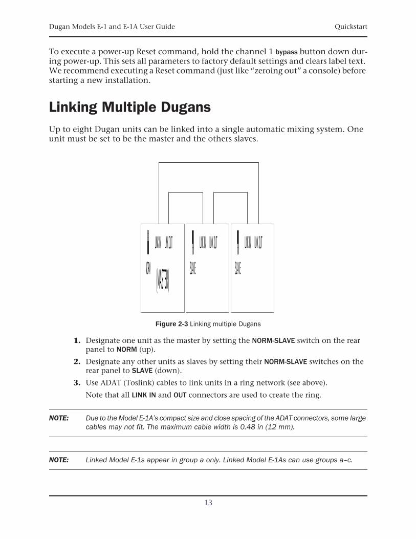
Linking Multiple DugansUp to eight Dugan units can be linked into a single automatic mixing system. Oneunit must be set to be the master and the others slaves.
Figure 2-3 Linking multiple Dugans
1. Designate one unit as the master by setting the NORM-SLAVE switch on the rearpanel to NORM (up).
2. Designate any other units as slaves by setting their NORM-SLAVE switches on therear panel to SLAVE (down).
3. Use ADAT (Toslink) cables to link units in a ring network (see above).
Note that all LINK IN and OUT connectors are used to create the ring.
NOTE: Due to the Model E-1A’s compact size and close spacing of the ADAT connectors, some largecables may not fit. The maximum cable width is 0.48 in (12 mm).
NOTE: Linked Model E-1s appear in group a only. Linked Model E-1As can use groups a–c.
13
Dugan Models E-1 and E-1A User Guide
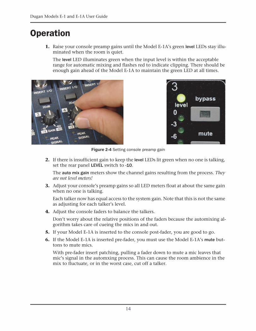
Operation1. Raise your console preamp gains until the Model E-1A’s green level LEDs stay illu-
minated when the room is quiet.
The level LED illuminates green when the input level is within the acceptablerange for automatic mixing and flashes red to indicate clipping. There should beenough gain ahead of the Model E-1A to maintain the green LED at all times.
Figure 2-4 Setting console preamp gain
2. If there is insufficient gain to keep the level LEDs lit green when no one is talking,set the rear panel LEVEL switch to -10.
The auto mix gain meters show the channel gains resulting from the process. Theyare not level meters!
3. Adjust your console’s preamp gains so all LED meters float at about the same gainwhen no one is talking.
Each talker now has equal access to the system gain. Note that this is not the sameas adjusting for each talker’s level.
4. Adjust the console faders to balance the talkers.
Don’t worry about the relative positions of the faders because the automixing al-gorithm takes care of cueing the mics in and out.
5. If your Model E-1A is inserted to the console post-fader, you are good to go.
6. If the Model E-1A is inserted pre-fader, you must use the Model E-1A’s mute but-tons to mute mics.
With pre-fader insert patching, pulling a fader down to mute a mic leaves thatmic’s signal in the automxing process. This can cause the room ambience in themix to fluctuate, or in the worst case, cut off a talker.
14
Dugan Models E-1 and E-1A User Guide
Chapter 3: Installation and Configuration
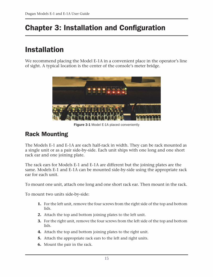
InstallationWe recommend placing the Model E-1A in a convenient place in the operator’s lineof sight. A typical location is the center of the console’s meter bridge.
Figure 3-1 Model E-1A placed conveniently
Rack Mounting
The Models E-1 and E-1A are each half-rack in width. They can be rack mounted asa single unit or as a pair side-by-side. Each unit ships with one long and one shortrack ear and one joining plate.
The rack ears for Models E-1 and E-1A are different but the joining plates are thesame. Models E-1 and E-1A can be mounted side-by-side using the appropriate rackear for each unit.
To mount one unit, attach one long and one short rack ear. Then mount in the rack.
To mount two units side-by-side:
1. For the left unit, remove the four screws from the right side of the top and bottomlids.
2. Attach the top and bottom joining plates to the left unit.
3. For the right unit, remove the four screws from the left side of the top and bottomlids.
4. Attach the top and bottom joining plates to the right unit.
5. Attach the appropriate rack ears to the left and right units.
6. Mount the pair in the rack.
15
Dugan Models E-1 and E-1A User Guide
Power Supply
Units shipped to the USA include a 12 V, 1.5 A, 120 VAC power supply. Contact thefactory if you require a different power supply. In an emergency, the Model E-1A canaccept power supplies within the following ranges:
• 12–24 VDC, either polarity, 1.5 A
• 9–18 VAC, 1.5 A
Audio Wiring
The ANALOG–DIGITAL switch selects which input is active, but both outputs remain active.
Analog I/O
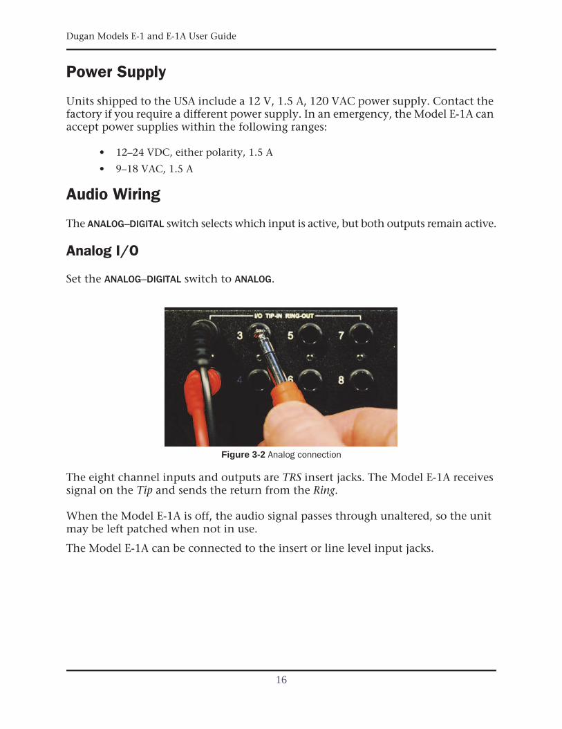
Set the ANALOG–DIGITAL switch to ANALOG.
Figure 3-2 Analog connection
The eight channel inputs and outputs are TRS insert jacks. The Model E-1A receivessignal on the Tip and sends the return from the Ring.
When the Model E-1A is off, the audio signal passes through unaltered, so the unitmay be left patched when not in use.
The Model E-1A can be connected to the insert or line level input jacks.
16
Dugan Models E-1 and E-1A User Guide Installation and Configuration
Insert1. Check the insert jack wiring on your mixing board.
If they are 1/4-in TRS jacks (wired tip = send, ring = return), use TRS-TRS insert ca-bles to connect the Model E-1A. Other configurations require special cables. TheModel E-1A is wired as follows: tip = input, ring = output.
2. Patch the audio channels in the insert loop (send-return) of each console input strip.
This is the normal way to connect the Model E-1A using a mic-level signal.
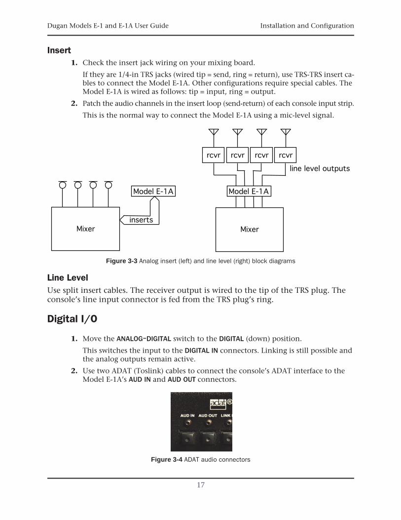
Figure 3-3 Analog insert (left) and line level (right) block diagrams
Line LevelUse split insert cables. The receiver output is wired to the tip of the TRS plug. Theconsole’s line input connector is fed from the TRS plug’s ring.
Digital I/O
1. Move the ANALOG–DIGITAL switch to the DIGITAL (down) position.
This switches the input to the DIGITAL IN connectors. Linking is still possible andthe analog outputs remain active.
2. Use two ADAT (Toslink) cables to connect the console’s ADAT interface to theModel E-1A’s AUD IN and AUD OUT connectors.
Figure 3-4 ADAT audio connectors
17
Dugan Models E-1 and E-1A User Guide
The Model E-1A has two digital operating modes:
• 8 ch: Eight automxing channels, linking possible
• 16 ch: Sixteen automixing channels, no linking
The LINK IN and LINK OUT connectors are reassigned as audio I/O for channels9–16.
To set 16 ch mode, you can use the Dugan Control Panel (see Chapter 4: DuganControl Panel), or a key command during startup (see Configuration on page 20).Since the Model E-1A’s front panel provides only eight channels, we strongly rec-ommend using the Dugan Control Panel to operate in 16 ch mode.
NOTE: Due to the Model E-1A’s compact size and close spacing of the ADAT connectors, some largecables may not fit. The maximum cable width is 0.48 in (12 mm).
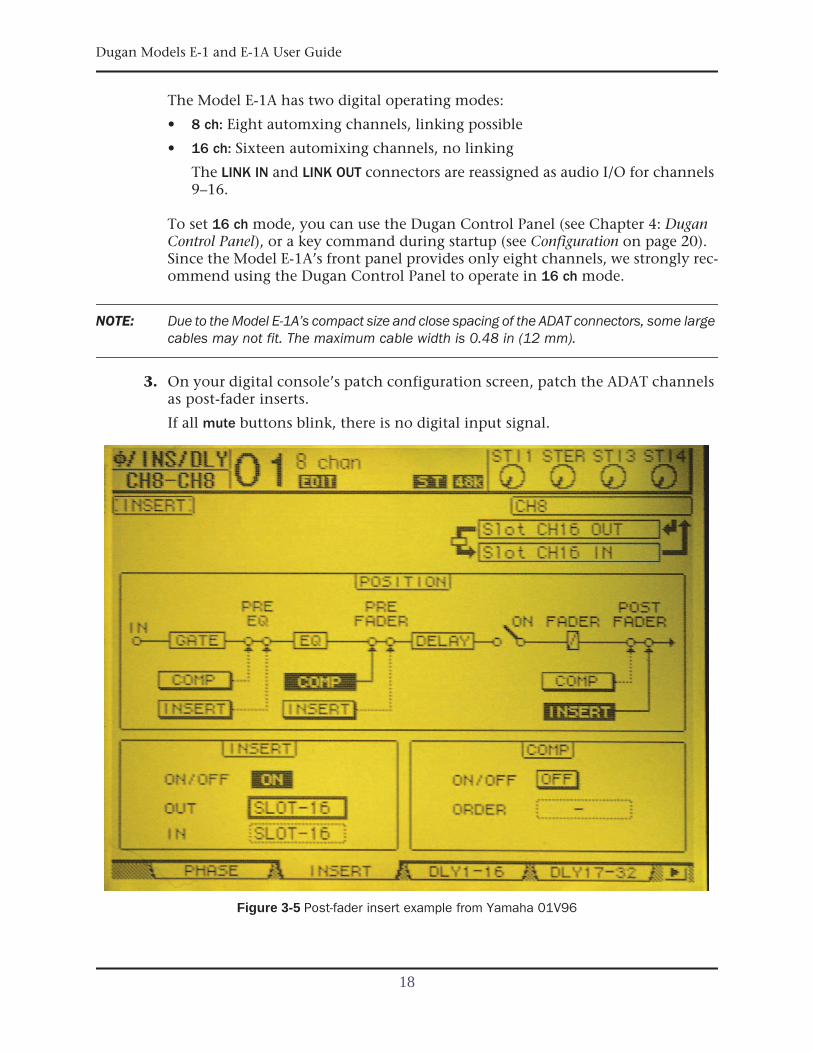
3. On your digital console’s patch configuration screen, patch the ADAT channelsas post-fader inserts.
If all mute buttons blink, there is no digital input signal.
Figure 3-5 Post-fader insert example from Yamaha 01V96
18
Dugan Models E-1 and E-1A User Guide Installation and Configuration
Signal Levels
Analog
The Model E-1A requires line level signals in the range -20 to +4 dBm; 0 dBm is optimal.The level LEDs light green for normal operation and red for overload.
If there is insufficient gain to keep the level LEDs lit green when no one is talking, setthe rear panel LEVEL switch to -10.
Digital
Set the console input gain trimmers so program levels at the insert sends cause thelevel LEDs to remain green whether someone is talking or not.
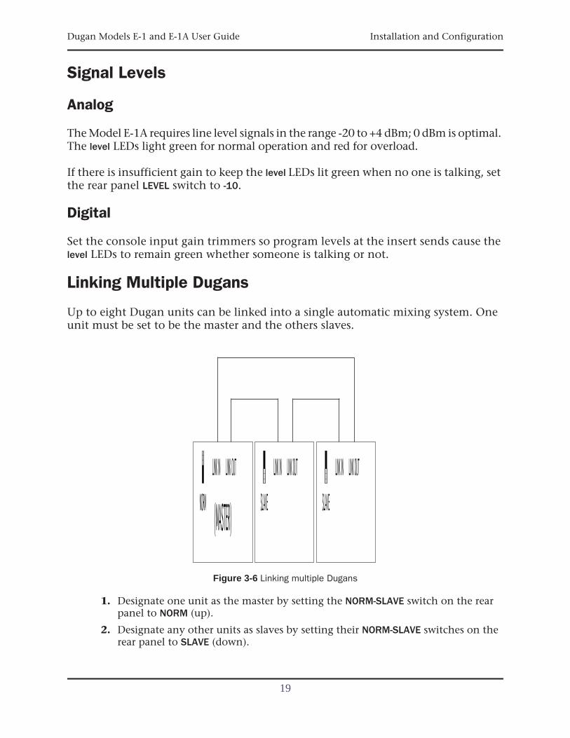
Linking Multiple Dugans
Up to eight Dugan units can be linked into a single automatic mixing system. Oneunit must be set to be the master and the others slaves.
Figure 3-6 Linking multiple Dugans
1. Designate one unit as the master by setting the NORM-SLAVE switch on the rearpanel to NORM (up).
2. Designate any other units as slaves by setting their NORM-SLAVE switches on therear panel to SLAVE (down).
19
Dugan Models E-1 and E-1A User Guide
3. Use ADAT (Toslink) cables to link units in a ring network (see below).
Note that all LINK IN and OUT connectors are used to create the ring.
NOTE: Due to the Model E-1A’s compact size and close spacing of the ADAT connectors, some largecables may not fit. The maximum cable width is 0.48 in (12 mm).
NOTE: Linked Model E-1s appear in group a only. Linked Model E-1As can use groups a–c.
Configuration
Power-up Commands
The Model E-1A can execute one of five commands during each power-up. Select thecommand by holding down a specific button during the entire power-up process,which takes just a few seconds. Power-up is complete after the LEDs stop flashing.
To execute more than one command, turn the unit off after it finishes powering up,and repeat for the next command.
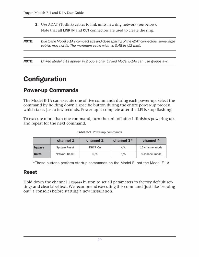
Table 3-1 Power-up commands
*These buttons perform startup commands on the Model E, not the Model E-1A
Reset
Hold down the channel 1 bypass button to set all parameters to factory default set-tings and clear label text. We recommend executing this command (just like “zeroingout” a console) before starting a new installation.
channel 1 channel 2 channel 3* channel 4
bypass System Reset DHCP On N/A 16 channel mode
mute Network Reset N/A N/A 8 channel mode
20
Dugan Models E-1 and E-1A User Guide Installation and Configuration
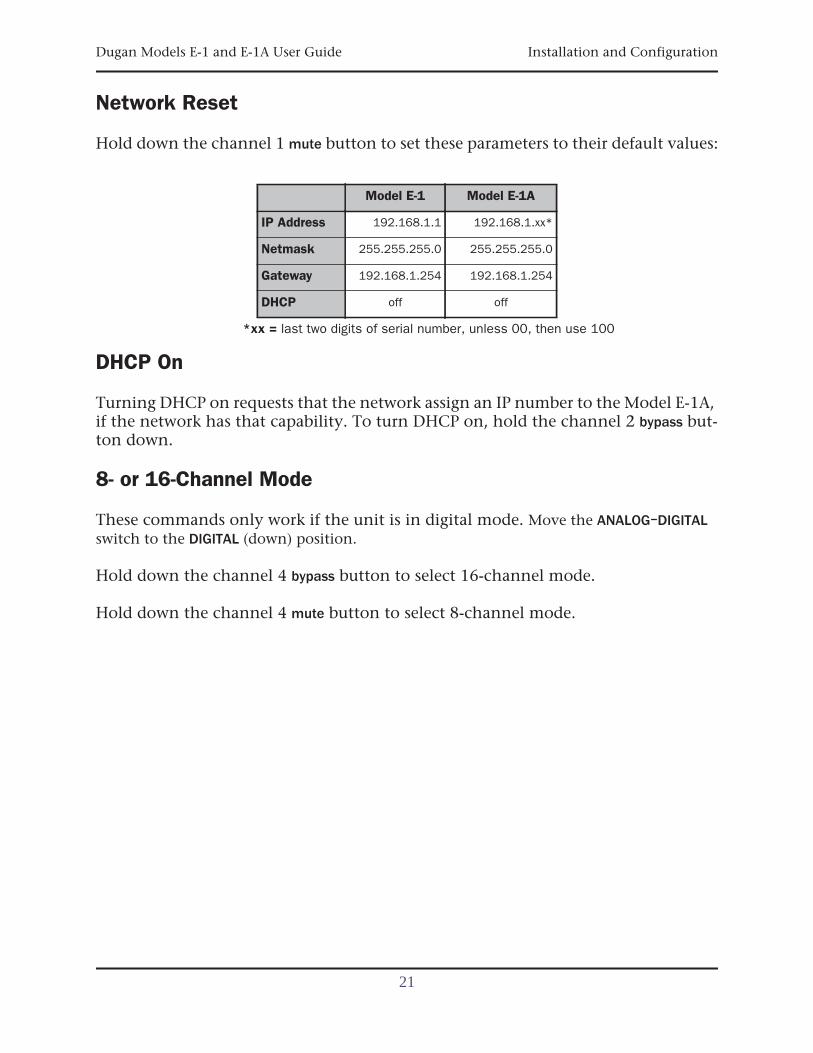
Network Reset
Hold down the channel 1 mute button to set these parameters to their default values:
*xx = last two digits of serial number, unless 00, then use 100
DHCP On
Turning DHCP on requests that the network assign an IP number to the Model E-1A,if the network has that capability. To turn DHCP on, hold the channel 2 bypass but-ton down.
8- or 16-Channel Mode
These commands only work if the unit is in digital mode. Move the ANALOG–DIGITALswitch to the DIGITAL (down) position.
Hold down the channel 4 bypass button to select 16-channel mode.
Hold down the channel 4 mute button to select 8-channel mode.
Model E-1 Model E-1A
IP Address 192.168.1.1 192.168.1.xx*
Netmask 255.255.255.0 255.255.255.0
Gateway 192.168.1.254 192.168.1.254
DHCP off off
21
Dugan Models E-1 and E-1A User Guide
Connecting to a Computer
Two Java applets are provided with the Model E-1A:
• The Dugan Control Panel offers expanded operational capabilities.
• The Dugan Utility helps you connect to a network and update the firmware.
Insert the USB thumb drive (or CD) supplied with the Model E-1A, or download thelatest version from:
http://www.dandugan.com/downloads
- OR -
http://tech.groups.yahoo.com/group/duganusers/files/
To connect the Model E-1A directly to a computer, use the rear panel Ethernet jack.An older PC may require a crossover cable. Use a straight Ethernet cable to connectto a network.
We strongly recommend that Windows users turn the Windows firewall off. TheWindows Firewall blocks port 9776 used by the Dugan software to communicate. Ifyou must leave the Windows firewall on, either open this port or use the workarounddescribed in Connecting when Windows Firewall is On on page 27.
We recommend turning off the computer’s WiFi during this process because it some-times interferes. You can turn it back on after the connection has been established.
For those who wish to set a specific IP address, proceed to Software Configuration for aSpecific IP Address on page 26.
22
Dugan Models E-1 and E-1A User Guide Installation and Configuration
Establishing Network Connections
We recommend completing your network connection with a computer before using theiPad app.
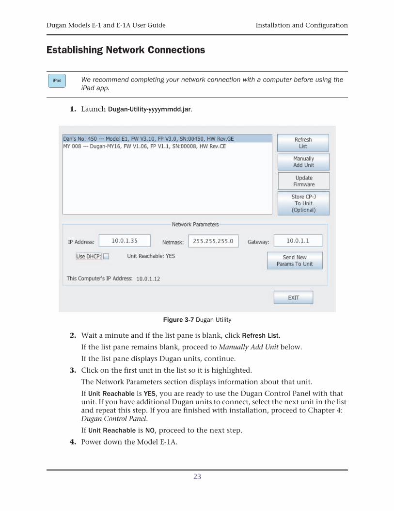
1. Launch Dugan-Utility-yyyymmdd.jar.
Figure 3-7 Dugan Utility
2. Wait a minute and if the list pane is blank, click Refresh List.
If the list pane remains blank, proceed to Manually Add Unit below.
If the list pane displays Dugan units, continue.
3. Click on the first unit in the list so it is highlighted.
The Network Parameters section displays information about that unit.
If Unit Reachable is YES, you are ready to use the Dugan Control Panel with thatunit. If you have additional Dugan units to connect, select the next unit in the listand repeat this step. If you are finished with installation, proceed to Chapter 4:Dugan Control Panel.
If Unit Reachable is NO, proceed to the next step.
4. Power down the Model E-1A.
iPad
23
Dugan Models E-1 and E-1A User Guide
5. Hold down the channel 1 mute button during the entire power up sequence.
Power up is finished when all LEDs stop flashing.
This resets all network parameters to their factory default values.
6. Click Refresh List.
7. Click on the first unit in the list so it is highlighted.
If Unit Reachable is YES, you are ready to use the Dugan Control Panel with thatunit. If you have additional Dugan units to connect, select the next unit in the listand repeat Step 3. If you are finished with installation, proceed to Chapter 4: Du-gan Control Panel.
If Unit Reachable is NO, proceed to the next step.
8. Select the Use DHCP parameter.
9. Click Send New Params to Unit.
10.Highlight the unit in the list pane again.
If Unit Reachable is YES, this unit is ready to use with the Dugan Control Panel. Ifyou have additional Dugan units to connect, select the next unit in the list andrepeat Step 3. If you are finished with installation, proceed to Chapter 4: DuganControl Panel.
If Unit Reachable is NO, proceed to the next step.
11.Copy This Computer’s IP Address to the IP Address field, and increase the value inthe last (fourth) group by one.
For example, if This Computer’s IP Address is 192.168.1.101, set IP Address to192.168.1.102.
12.Click Send New Params to Unit.
13.Highlight the unit in the list pane again.
If Unit Reachable is YES, this unit is ready to use with the Dugan Control Panel. Ifyou have additional Dugan units to connect, select the next unit in the list andrepeat Step 3. If you are finished with installation, proceed to Chapter 4: DuganControl Panel.
If Unit Reachable is NO, see Using the Internally Stored Dugan Control Panel on page 25.
24
Dugan Models E-1 and E-1A User Guide Installation and Configuration
Manually Add Unit
If the Dugan unit does not appear in the Dugan Utility list pane, you can manuallyadd the unit:
1. Power down the Model E-1A.
2. Hold down Channel 1’s mute button and power up the unit.
This performs a network reset.
3. Click Manually Add Unit.
4. Enter the default IP address: 192.168.1.xx
xx = last two digits of serial number, unless they are 00, in which case enter 100.
5. Click OK to exit the dialog.
6. Click Refresh List.
If the list pane is still blank, see Using the Internally Stored Dugan Control Panel onpage 25.
Using the Internally Stored Dugan Control Panel
Normally, theDuganControlPanel is run fromtheDugan-Control-Panel-vxxx.jarfile. However, if for any reason you do not have that file or an Internet connection,you can run the Dugan Control Panel from a copy stored in the unit (see Chapter 6:Updates).
It is not currently possible to run the internally stored Dugan Control Panel from an iPad.
To run the internally stored Dugan Control Panel:
1. Launch your browser.
2. Enter the IP Address of the unit.
If you do not know the IP Address, see Network Reset to set it to a known address.
3. Since the Top Pane will be empty, open a separate browser tab for each unit youwish to operate and enter its IP Address.
If this does not work, consult the duganusers Yahoo group (http://tech.groups.ya-hoo.com/group/duganusers) or contact Dan.
iPad
25
Dugan Models E-1 and E-1A User Guide
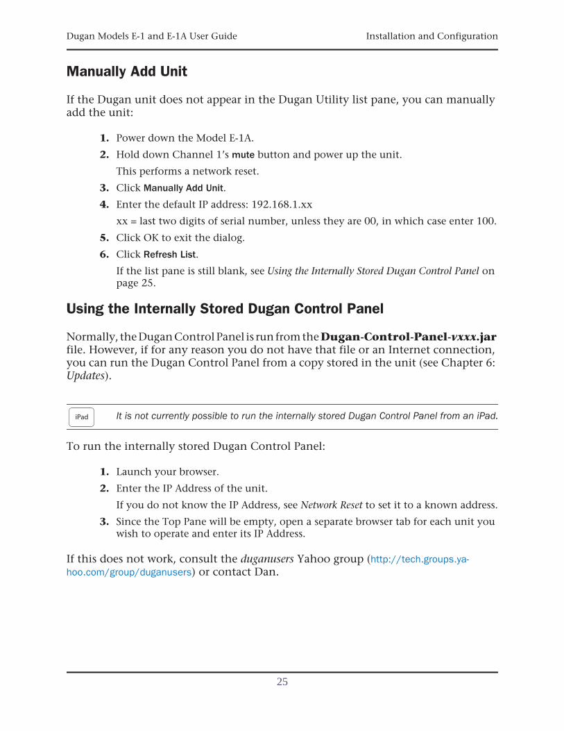
Software Configuration for a Specific IP Address
This section explains to users with IT expertise how to set a specific IP address for anyDugan unit on the network.
1. Launch Dugan-Utility-vxx.jar.
Figure 3-8 Dugan Utility
2. Wait a minute and if the list pane is blank, click Refresh List.
If the list pane remains blank, skip back to Manually Add Unit above.
If the list pane displays Dugan units, continue.
3. Click on the first unit in the list so it is highlighted.
The Network Parameters section displays information about that unit.
4. If Use DHCP is selected, de-select it.
5. Enter the desired IP address into the IP Address field.
6. Click Send New Params to Unit.
The Model E-1A will reboot.
26
Dugan Models E-1 and E-1A User Guide Installation and Configuration
Connecting when Windows Firewall is On
The Windows Firewall blocks access to port 9776 that is used by the Dugan software.If you must leave the Windows Firewall on, you can operate the Dugan Control Panelin a browser window with one connected unit per tab.
1. Enter the Model E-1A’s IP address directly in the browser’s address field.
The browser uses the Dugan Control Panel that is stored in the Model E-1A’s hard-ware, not the version that you may have downloaded to your computer.
The unit will not show up in the top pane but the control panel will still work.
2. If you have multiple Dugan units, create a browser tab for each one and enter itsIP Address.
3. Switch tabs to control different units.
27

Dugan Models E-1 and E-1A User Guide
28
Dugan Models E-1 and E-1A User Guide
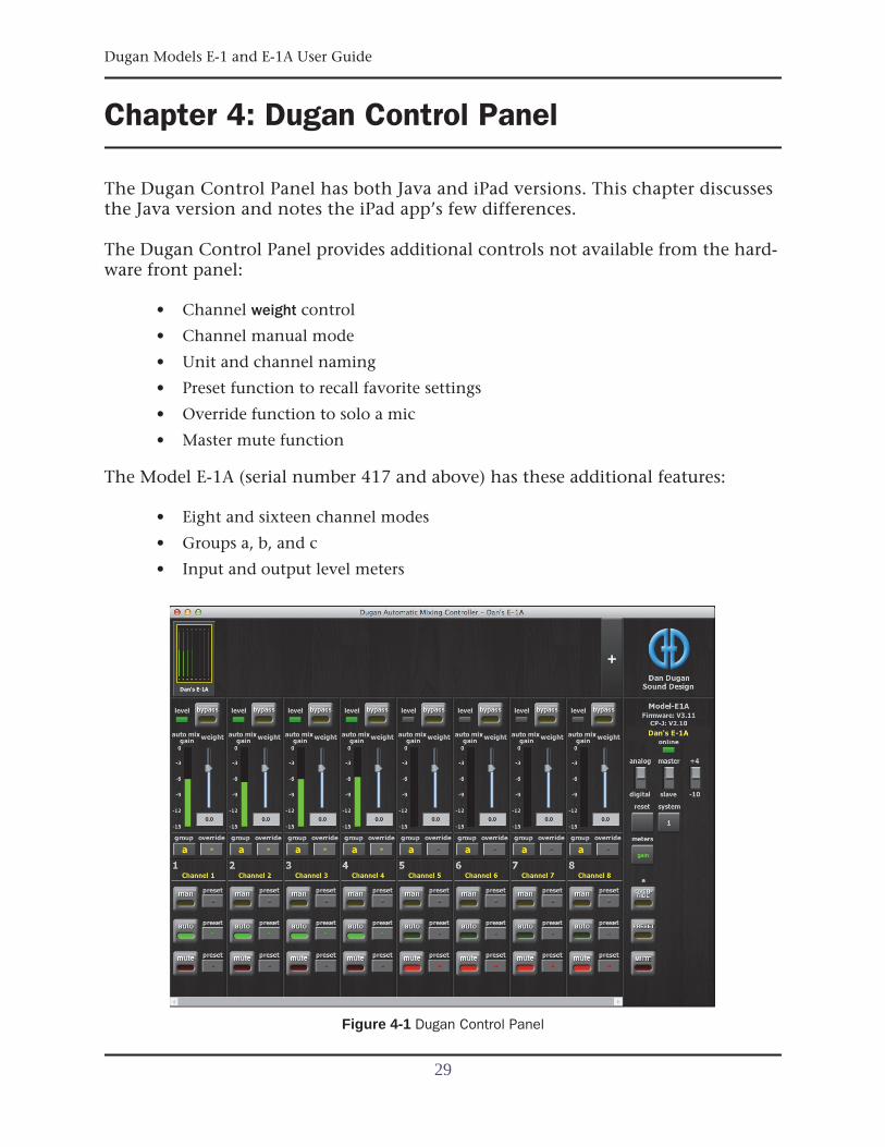
Chapter 4: Dugan Control Panel
The Dugan Control Panel has both Java and iPad versions. This chapter discussesthe Java version and notes the iPad app’s few differences.
The Dugan Control Panel provides additional controls not available from the hard-ware front panel:
• Channel weight control
• Channel manual mode
• Unit and channel naming
• Preset function to recall favorite settings
• Override function to solo a mic
• Master mute function
The Model E-1A (serial number 417 and above) has these additional features:
• Eight and sixteen channel modes
• Groups a, b, and c
• Input and output level meters
Figure 4-1 Dugan Control Panel
29
Dugan Models E-1 and E-1A User Guide
LaunchtheDugan-Control-Panel-vxxx.jar. If this file isnotavailableandyouhavean Internet connection, you can obtain the latest version from:
http://www.dandugan.com/downloads
- OR -
http://tech.groups.yahoo.com/group/duganusers/files/
If you do not have an Internet connection, you can use the version of the DuganControl Panel stored inside the unit’s firmware. See Using the Internally Stored DuganControl Panel on page 25.
The Dugan Control Panel has three panes. The controls displayed in these panes de-pend on which Dugan device is selected in the Top Pane.
The Dugan Control Panel is divided into three panes:
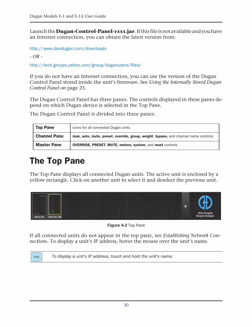
The Top PaneThe Top Pane displays all connected Dugan units. The active unit is enclosed by ayellow rectangle. Click on another unit to select it and deselect the previous unit.
Figure 4-2 Top Pane
If all connected units do not appear in the top pane, see Establishing Network Con-nections. To display a unit’s IP address, hover the mouse over the unit’s name.
To display a unit’s IP address, touch and hold the unit’s name.
Top Pane icons for all connected Dugan units
Channel Pane man, auto, mute, preset, override, group, weight, bypass, and channel name controls
Master Pane OVERRIDE, PRESET, MUTE, meters, system, and reset controls
iPad
30
Dugan Models E-1 and E-1A User Guide Dugan Control Panel
Setting Controls and Naming Units/Channels
Setting Controls
Controls can be adjusted five ways:
• Enter a dB value in the numeric field.
• Drag in the numeric field (not on iPad).
When a slider is present:
• Drag the slider up or down.
• Click in the slider track to raise or lower the value by 0.5 dB.
• Ctrl-click anywhere on the slider to reset its value to 0 (touch and hold on iPad).
Naming Units and Channels
Connected units are displayed in the top pane in alphabetical order. To display themin your own order, use names with number prefixes.
To name a unit and its channels:
1. Select a unit in the top pane.
2. Select the yellow text in the right pane (under the Dugan logo) and type a name.
3. Press the Enter key on the keyboard to set the name.
4. To name a channel, select the yellow text and type a name.
5. Press the Enter key on the keyboard to set the name.
Channel naming is cleared by pressing reset (see page 40).
When the unit is powered up, channel modes are determined by their preset modes;all other settings are retained.
After configuring settings with the Dugan Control Panel, it can be disconnected. Allsettings are retained and the unit continues to function on its own.
31
Dugan Models E-1 and E-1A User Guide
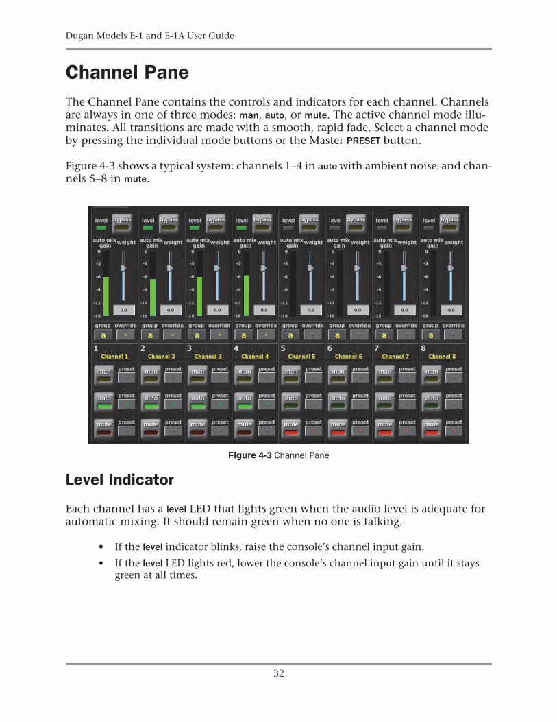
Channel PaneThe Channel Pane contains the controls and indicators for each channel. Channelsare always in one of three modes: man, auto, or mute. The active channel mode illu-minates. All transitions are made with a smooth, rapid fade. Select a channel modeby pressing the individual mode buttons or the Master PRESET button.
Figure 4-3 shows a typical system: channels 1–4 in auto with ambient noise, and chan-nels 5–8 in mute.
Figure 4-3 Channel Pane
Level Indicator
Each channel has a level LED that lights green when the audio level is adequate forautomatic mixing. It should remain green when no one is talking.
• If the level indicator blinks, raise the console’s channel input gain.
• If the level LED lights red, lower the console’s channel input gain until it staysgreen at all times.
32
Dugan Models E-1 and E-1A User Guide Dugan Control Panel
Bypass
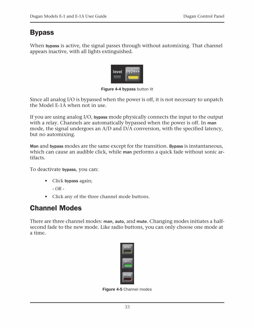
When bypass is active, the signal passes through without automixing. That channelappears inactive, with all lights extinguished.
Figure 4-4 bypass button lit
Since all analog I/O is bypassed when the power is off, it is not necessary to unpatchthe Model E-1A when not in use.
If you are using analog I/O, bypass mode physically connects the input to the outputwith a relay. Channels are automatically bypassed when the power is off. In manmode, the signal undergoes an A/D and D/A conversion, with the specified latency,but no automixing.
Man and bypass modes are the same except for the transition. Bypass is instantaneous,which can cause an audible click, while man performs a quick fade without sonic ar-tifacts.
To deactivate bypass, you can:
• Click bypass again;
- OR -
• Click any of the three channel mode buttons.
Channel Modes
There are three channel modes: man, auto, and mute. Changing modes initiates a half-second fade to the new mode. Like radio buttons, you can only choose one mode ata time.
Figure 4-5 Channel modes
33
Dugan Models E-1 and E-1A User Guide
Man
In man mode there is no automixing, and the signal passes through at unity gain.
Even though man and bypass modes perform similar functions, we recommend usingman during live mixing to prevent clicks.
Auto
This is the normal Dugan automixing mode.
Mute
The channel is muted when mute is active.
Preset
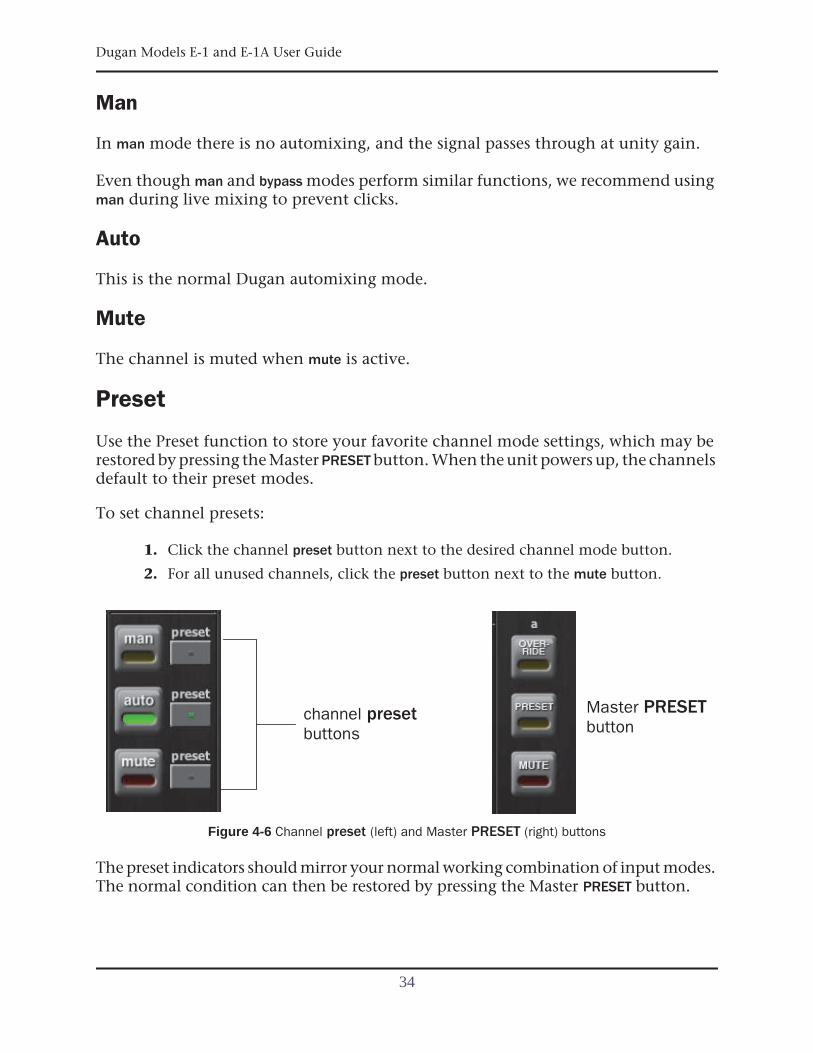
Use the Preset function to store your favorite channel mode settings, which may berestored by pressing the Master PRESET button. When the unit powers up, the channelsdefault to their preset modes.
To set channel presets:
1. Click the channel preset button next to the desired channel mode button.
2. For all unused channels, click the preset button next to the mute button.
Figure 4-6 Channel preset (left) and Master PRESET (right) buttons
The preset indicators should mirror your normal working combination of input modes.The normal condition can then be restored by pressing the Master PRESET button.
channel presetbuttons
Master PRESETbutton
34
Dugan Models E-1 and E-1A User Guide Dugan Control Panel
Channel Groups
Each channel can be assigned to one group: a, b, or c. Each group functions as a sep-arate, independent automatic mixer that can span multiple linked Dugans.
Applications where groups are helpful include:
• Separate Rooms: Assign the mics in each room to different groups so they func-tion as separate automatic mixers.
• Stereo Panning: Assign the mics panned left, right, and center to groups a, b, andc, respectively, to maintain a stable stereo ambience.
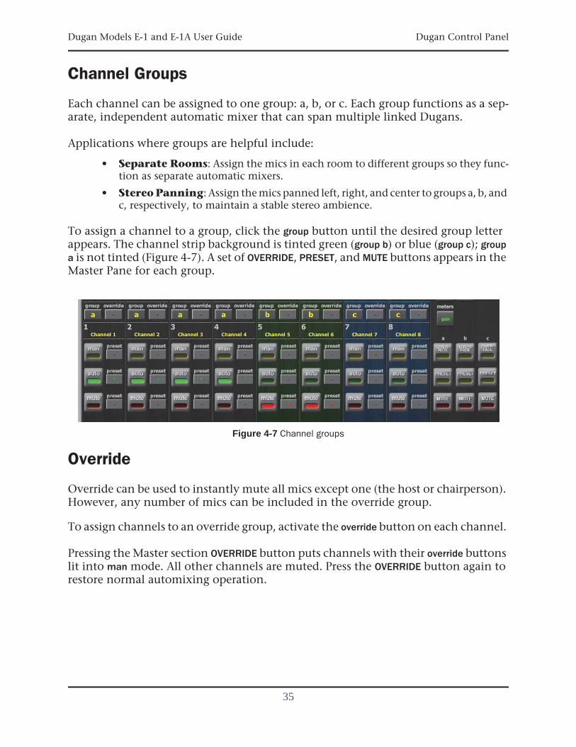
To assign a channel to a group, click the group button until the desired group letterappears. The channel strip background is tinted green (group b) or blue (group c); groupa is not tinted (Figure 4-7). A set of OVERRIDE, PRESET, and MUTE buttons appears in theMaster Pane for each group.
Figure 4-7 Channel groups
Override
Override can be used to instantly mute all mics except one (the host or chairperson).However, any number of mics can be included in the override group.
To assign channels to an override group, activate the override button on each channel.
Pressing the Master section OVERRIDE button puts channels with their override buttonslit into man mode. All other channels are muted. Press the OVERRIDE button again torestore normal automixing operation.
35
Dugan Models E-1 and E-1A User Guide
Meters
The meters have three display modes.
Table 4-1 Meter modes
The default meter display is auto mix gain. This is the most useful choice during normaloperation; the input and output meters are only used when setting or checking levels.
Click on the Master meters button to toggle through the three meter display modes.
Weight Controls
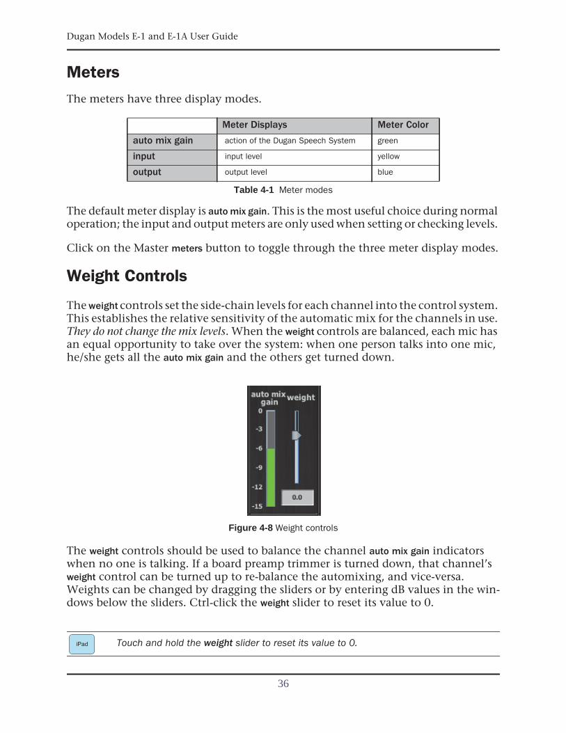
The weight controls set the side-chain levels for each channel into the control system.This establishes the relative sensitivity of the automatic mix for the channels in use.They do not change the mix levels. When the weight controls are balanced, each mic hasan equal opportunity to take over the system: when one person talks into one mic,he/she gets all the auto mix gain and the others get turned down.
Figure 4-8 Weight controls
The weight controls should be used to balance the channel auto mix gain indicatorswhen no one is talking. If a board preamp trimmer is turned down, that channel’sweight control can be turned up to re-balance the automixing, and vice-versa.Weights can be changed by dragging the sliders or by entering dB values in the win-dows below the sliders. Ctrl-click the weight slider to reset its value to 0.
Touch and hold the weight slider to reset its value to 0.
Meter Displays Meter Color
auto mix gain action of the Dugan Speech System green
input input level yellow
output output level blue
iPad
36
Dugan Models E-1 and E-1A User Guide Dugan Control Panel
It is important to understand that the Speech System works by detecting the ratios ofthe levels between channels, not their absolute levels. The weight control is not a gatethreshold!
The following example explains how weight works (see Figure 4-9).
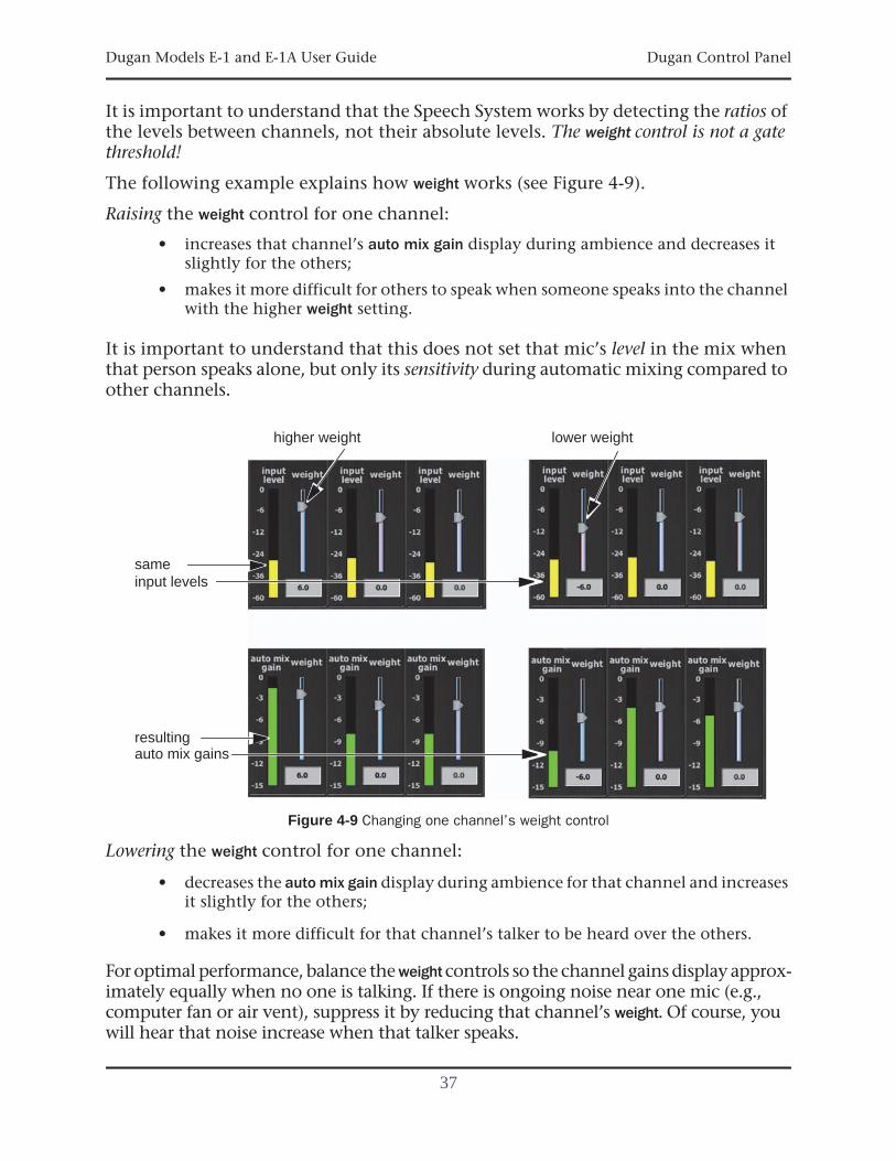
Raising the weight control for one channel:
• increases that channel’s auto mix gain display during ambience and decreases itslightly for the others;
• makes it more difficult for others to speak when someone speaks into the channelwith the higher weight setting.
It is important to understand that this does not set that mic’s level in the mix whenthat person speaks alone, but only its sensitivity during automatic mixing compared toother channels.
Figure 4-9 Changing one channel’s weight control
Lowering the weight control for one channel:
• decreases the auto mix gain display during ambience for that channel and increasesit slightly for the others;
• makes it more difficult for that channel’s talker to be heard over the others.
For optimal performance, balance the weight controls so the channel gains display approx-imately equally when no one is talking. If there is ongoing noise near one mic (e.g.,computer fan or air vent), suppress it by reducing that channel’s weight. Of course, youwill hear that noise increase when that talker speaks.
higher weight lower weight
same
resultingauto mix gains
input levels
37
Dugan Models E-1 and E-1A User Guide
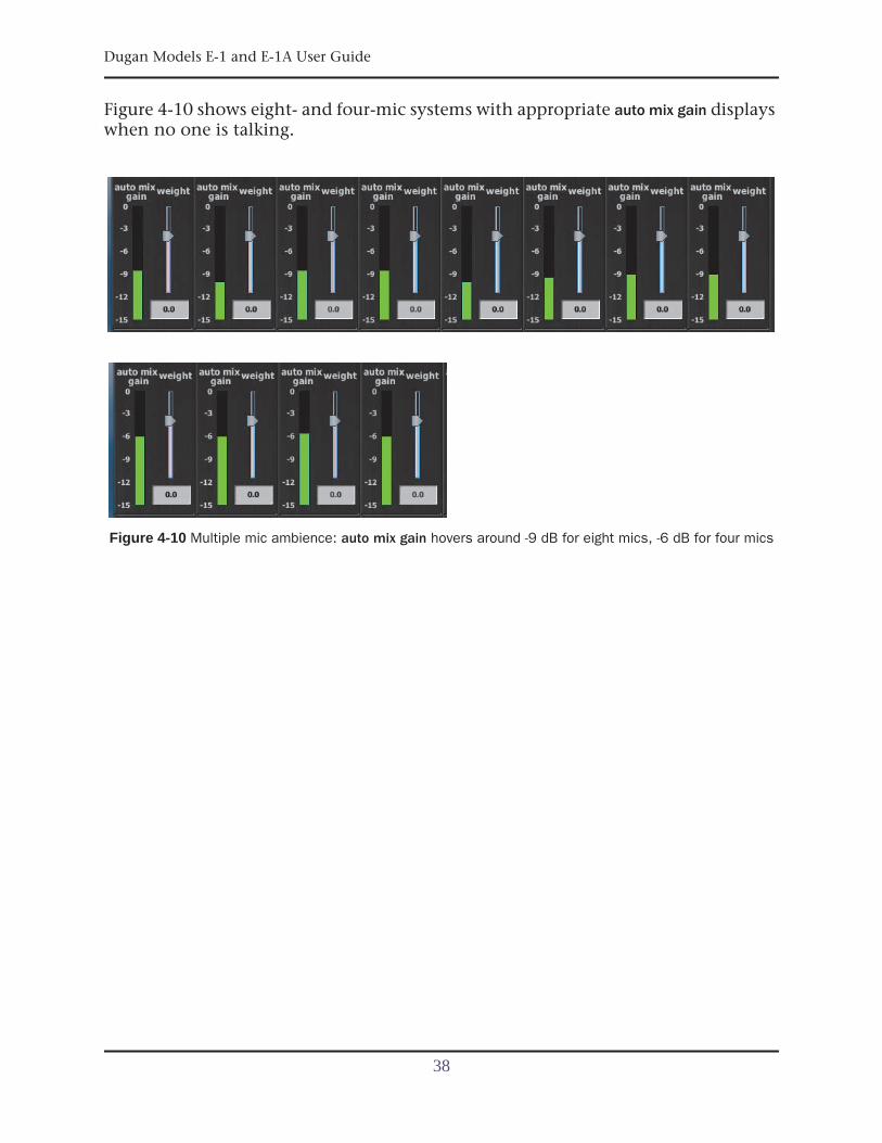
Figure 4-10 shows eight- and four-mic systems with appropriate auto mix gain displayswhen no one is talking.
Figure 4-10 Multiple mic ambience: auto mix gain hovers around -9 dB for eight mics, -6 dB for four mics
38
Dugan Models E-1 and E-1A User Guide Dugan Control Panel
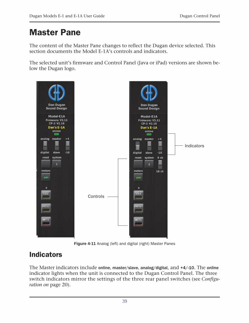
Master PaneThe content of the Master Pane changes to reflect the Dugan device selected. Thissection documents the Model E-1A’s controls and indicators.
The selected unit’s firmware and Control Panel (Java or iPad) versions are shown be-low the Dugan logo.
Figure 4-11 Analog (left) and digital (right) Master Panes
Indicators
The Master indicators include online, master/slave, analog/digital, and +4/-10. The onlineindicator lights when the unit is connected to the Dugan Control Panel. The threeswitch indicators mirror the settings of the three rear panel switches (see Configu-ration on page 20).
Indicators
Controls
39
Dugan Models E-1 and E-1A User Guide
Controls
The Master controls, located on the far right, include reset, system, meters, OVERRIDE,PRESET, and MUTE. A set of buttons appears for each active group.
Reset
Press the reset button to restore the unit to its default settings.
System
When multiple Dugan units are linked, groups a, b, and c span linked units and operateas independent automatic mixers.
It is possible to have multiple systems of linked units on your network. These unitswill all appear in the top pane. The Model E-1A allows 16 systems in a network.
In the rare instance that requires multiple systems:
1. Select the first unit to include in the system by clicking it in the top pane.
2. Click the system button and select a unique number for that system.
3. Repeat for each unit in that physically linked system, making sure to use the samenumber for each unit in the system.
4. Repeat steps 1–3 for each system.
Eight or Sixteen Channel Mode
When the Model E-1A is set for digital I/O, the 8-16 Ch switch appears in the Mastersection. Set the switch to the desired mode. In 16 Ch mode, the rear panel LINK con-nectors are used for audio I/O for channels 9–16 instead of linking.
Meters
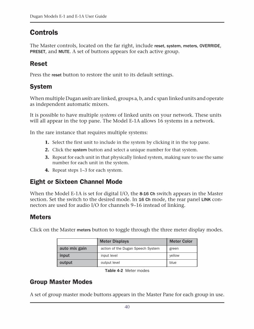
Click on the Master meters button to toggle through the three meter display modes.
Table 4-2 Meter modes
Group Master Modes
A set of group master mode buttons appears in the Master Pane for each group in use.
Meter Displays Meter Color
auto mix gain action of the Dugan Speech System green
input input level yellow
output output level blue
40
Dugan Models E-1 and E-1A User Guide Dugan Control Panel
OverrideActivating the Master OVERRIDE button has the following effect on individual channels:
• Channel override button active: puts the channel in man mode with full gain (noautomixing);
- OR -
• Channel override button inactive: mutes the channel.
Select channel(s) to include in the override group by activating their override button(s).
Remove channel(s) from the override group by deactivating their override button(s).
PresetPressing the Master PRESET button sets the channel modes (man, auto, mute) to thoseshown on each channel’s preset buttons. Use these settings to store your favorite chan-nel mode settings. When the unit powers up, the channels default to their presetmodes.
MutePress the MUTE button to mute a group. Press it again to unmute the group.
41

Dugan Models E-1 and E-1A User Guide
42
Dugan Models E-1 and E-1A User Guide
Chapter 5: Standalone Hardware Operation
The Dugan Control Panel software provides the complete complement of controlsfor the Model E-1A. However, if for any reason you cannot or do not wish to connectthe Dugan Control Panel, you can operate the hardware as a standalone device.
The limitations in standalone operation are:
• Eight channels
• No access to channel weight controls, man mode, preset function, override function
• No unit or channel naming
• No access to groups, input/output level meters, or Master MUTE
Settings1. Put all the live mic channels in automatic mixing mode by deactivating bypass
and mute.
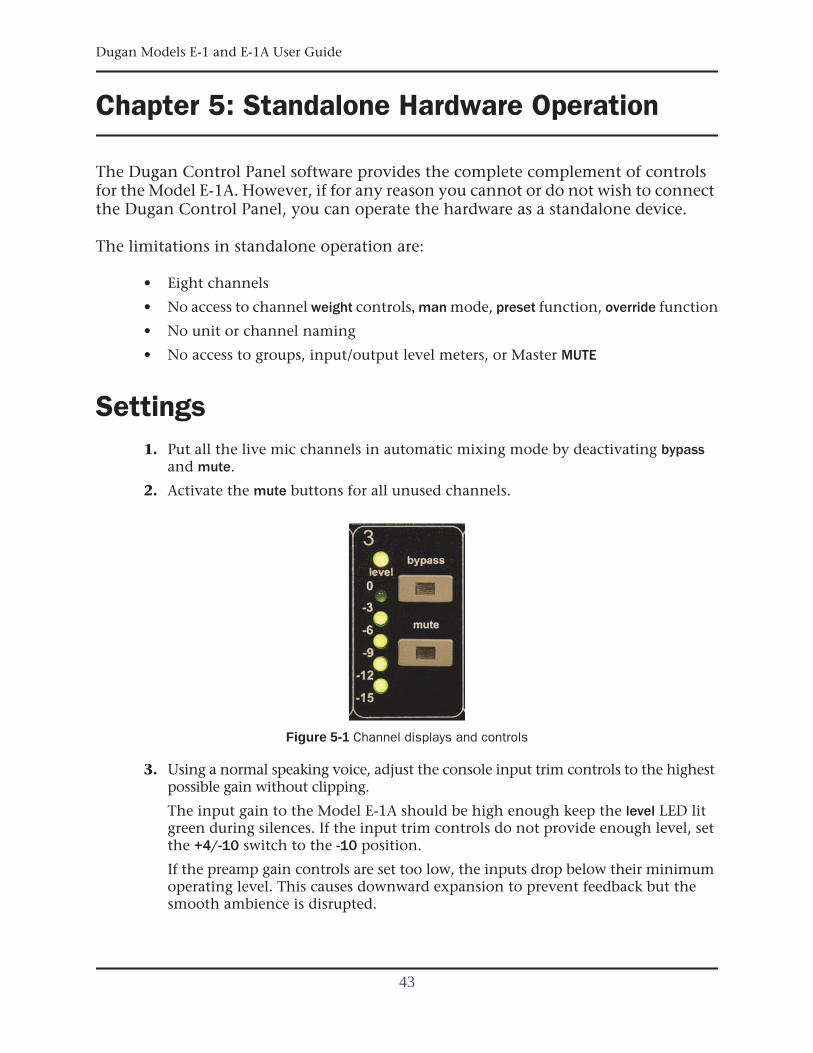
2. Activate the mute buttons for all unused channels.
Figure 5-1 Channel displays and controls
3. Using a normal speaking voice, adjust the console input trim controls to the highestpossible gain without clipping.
The input gain to the Model E-1A should be high enough keep the level LED litgreen during silences. If the input trim controls do not provide enough level, setthe +4/-10 switch to the -10 position.
If the preamp gain controls are set too low, the inputs drop below their minimumoperating level. This causes downward expansion to prevent feedback but thesmooth ambience is disrupted.
43
Dugan Models E-1 and E-1A User Guide
4. Set the console faders to your normal operating positions.
5. Balance the preamp gain controls so the fluctuating ambient noise registers equal-ly on the Model E-1A’s meters.
Note that raising the preamp gain of one channel causes its gain to rise and theothers to fall; it’s a balancing act. When balanced, all mics have equal access tothe system gain.
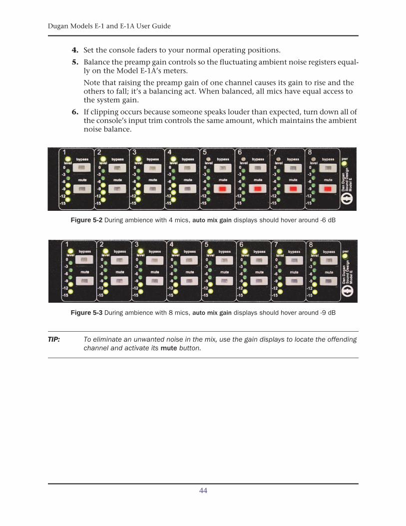
6. If clipping occurs because someone speaks louder than expected, turn down all ofthe console’s input trim controls the same amount, which maintains the ambientnoise balance.
Figure 5-2 During ambience with 4 mics, auto mix gain displays should hover around -6 dB
Figure 5-3 During ambience with 8 mics, auto mix gain displays should hover around -9 dB
TIP: To eliminate an unwanted noise in the mix, use the gain displays to locate the offendingchannel and activate its mute button.
44
Dugan Models E-1 and E-1A User Guide Standalone Hardware Operation
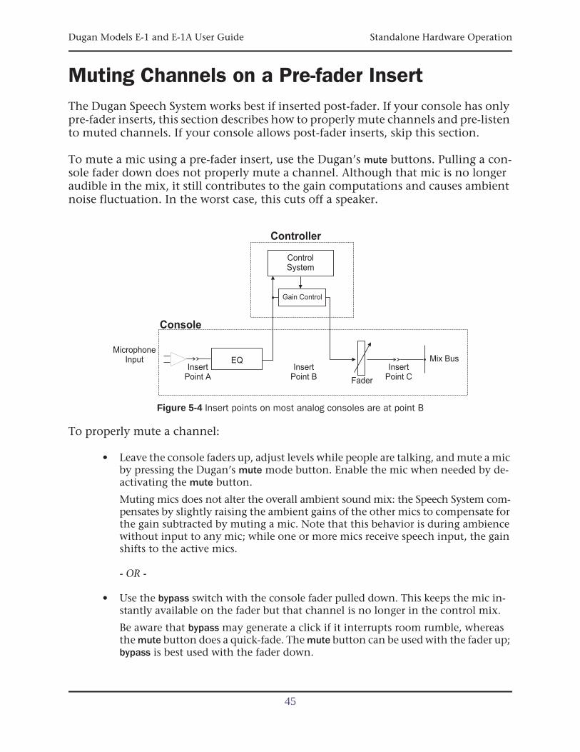
Muting Channels on a Pre-fader InsertThe Dugan Speech System works best if inserted post-fader. If your console has onlypre-fader inserts, this section describes how to properly mute channels and pre-listento muted channels. If your console allows post-fader inserts, skip this section.
To mute a mic using a pre-fader insert, use the Dugan’s mute buttons. Pulling a con-sole fader down does not properly mute a channel. Although that mic is no longeraudible in the mix, it still contributes to the gain computations and causes ambientnoise fluctuation. In the worst case, this cuts off a speaker.
Figure 5-4 Insert points on most analog consoles are at point B
To properly mute a channel:
• Leave the console faders up, adjust levels while people are talking, and mute a micby pressing the Dugan’s mute mode button. Enable the mic when needed by de-activating the mute button.
Muting mics does not alter the overall ambient sound mix: the Speech System com-pensates by slightly raising the ambient gains of the other mics to compensate forthe gain subtracted by muting a mic. Note that this behavior is during ambiencewithout input to any mic; while one or more mics receive speech input, the gainshifts to the active mics.
- OR -
• Use the bypass switch with the console fader pulled down. This keeps the mic in-stantly available on the fader but that channel is no longer in the control mix.
Be aware that bypass may generate a click if it interrupts room rumble, whereasthe mute button does a quick-fade. The mute button can be used with the fader up;bypass is best used with the fader down.
ControlSystem
Controller
Console
Mix BusInsert
Point AInsert
Point B Fader
MicrophoneInput EQ
Gain Control
InsertPoint C
45

Dugan Models E-1 and E-1A User Guide
Pre-listening to Muted Channels Using a Post-fader Insert
If signal through the Dugan is required to pre-listen to a mic, pull the fader down andput that Dugan channel in bypass mode. When your mic check is done, switch thechannel out of bypass and raise the fader so you will be ready to up-cut automatically.
46
Dugan Models E-1 and E-1A User Guide
Chapter 6: Updates
Updates for the Model E-1/E-1A can be downloaded.
To update the firmware in your Dugan unit, iPad users must connect a computer and runthe Dugan Utility.
To update the Dugan Control Panel for iPad, connect to the Apple App Store.
To update your device’s software and firmware:
1. Connect to the Internet and download Dugan-Software-yyyymmdd.zip from:
http://www.dandugan.com/downloads/
- OR -
http://tech.groups.yahoo.com/group/duganusers/files/
After the download is complete, the Internet connection is no longer necessary.
2. Unzip the software package.
It contains the Dugan-Control-Panel-vxxx.jar and Dugan-Utility-yyyym-mdd.jar. The Dugan Utility contains the latest versions of both the firmware andthe safety copy of the Dugan Control Panel that loads automatically into the unit.
To revert to a previous version, use the older version of the Dugan Utility.
3. Connect the computer to the Dugan units you wish to update.
4. Launch Dugan-Utility-yyyymmdd.jar.
The Dugan Utility window appears.
iPad
47
Dugan Models E-1 and E-1A User Guide
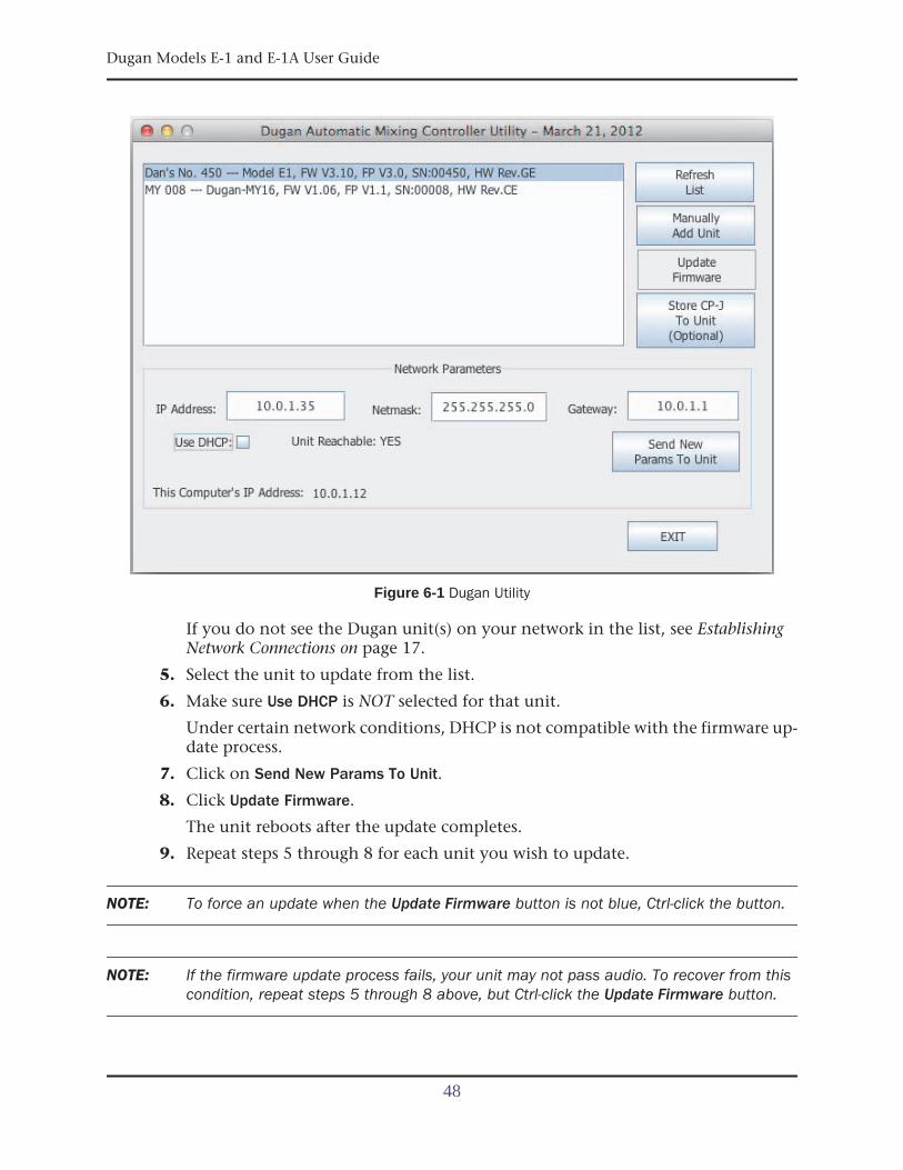
Figure 6-1 Dugan Utility
If you do not see the Dugan unit(s) on your network in the list, see EstablishingNetwork Connections on page 17.
5. Select the unit to update from the list.
6. Make sure Use DHCP is NOT selected for that unit.
Under certain network conditions, DHCP is not compatible with the firmware up-date process.
7. Click on Send New Params To Unit.
8. Click Update Firmware.
The unit reboots after the update completes.
9. Repeat steps 5 through 8 for each unit you wish to update.
NOTE: To force an update when the Update Firmware button is not blue, Ctrl-click the button.
NOTE: If the firmware update process fails, your unit may not pass audio. To recover from thiscondition, repeat steps 5 through 8 above, but Ctrl-click the Update Firmware button.
48
Dugan Models E-1 and E-1A User Guide
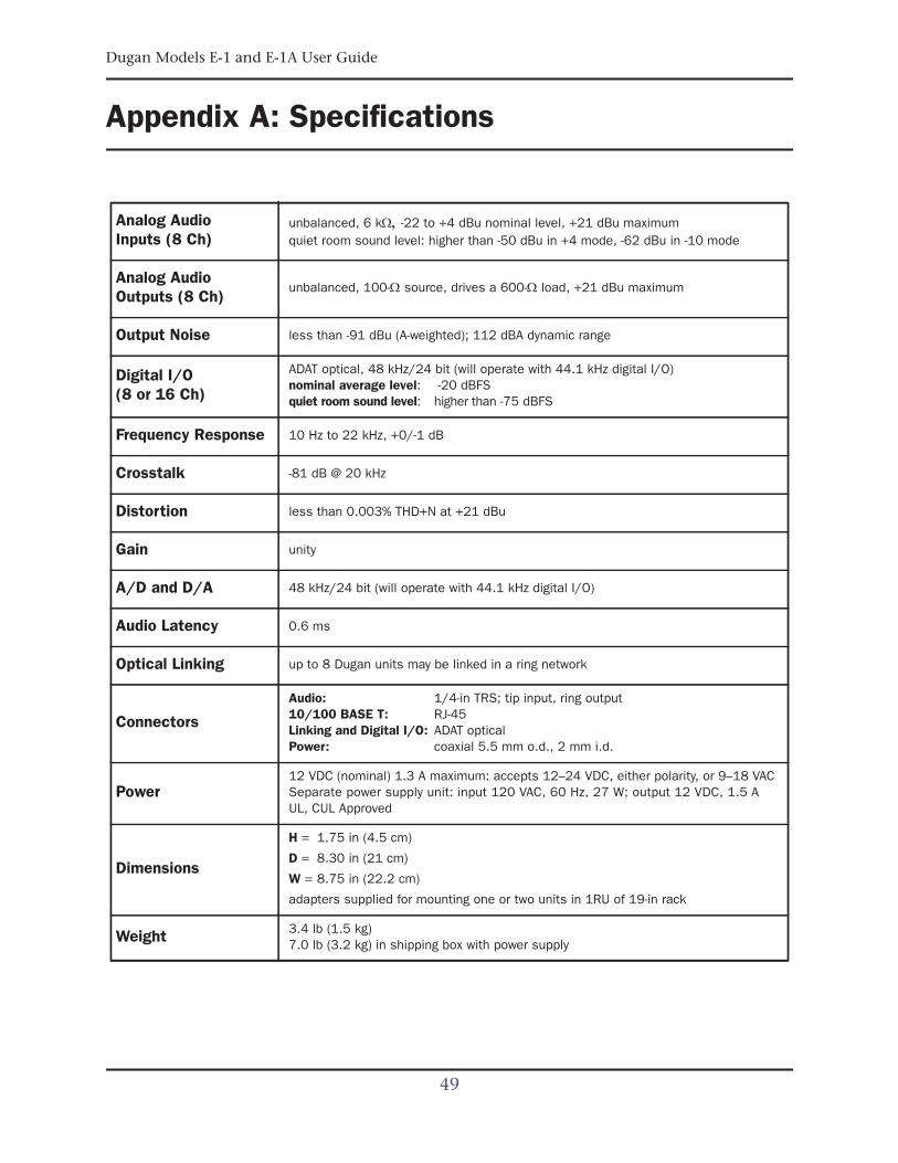
Appendix A: Specifications
Analog AudioInputs (8 Ch)
unbalanced, 6 k-22 to +4 dBu nominal level, +21 dBu maximumquiet room sound level: higher than -50 dBu in +4 mode, -62 dBu in -10 mode
Analog AudioOutputs (8 Ch)
unbalanced, 100- source, drives a 600- load, +21 dBu maximum
Output Noise less than -91 dBu (A-weighted); 112 dBA dynamic range
Digital I/O(8 or 16 Ch)
ADAT optical, 48 kHz/24 bit (will operate with 44.1 kHz digital I/O)nominal average level: -20 dBFSquiet room sound level: higher than -75 dBFS
Frequency Response 10 Hz to 22 kHz, +0/-1 dB
Crosstalk -81 dB @ 20 kHz
Distortion less than 0.003% THD+N at +21 dBu
Gain unity
A/D and D/A 48 kHz/24 bit (will operate with 44.1 kHz digital I/O)
Audio Latency 0.6 ms
Optical Linking up to 8 Dugan units may be linked in a ring network
Connectors
Audio: 1/4-in TRS; tip input, ring output10/100 BASE T: RJ-45Linking and Digital I/O: ADAT opticalPower: coaxial 5.5 mm o.d., 2 mm i.d.
Power12 VDC (nominal) 1.3 A maximum: accepts 12–24 VDC, either polarity, or 9–18 VACSeparate power supply unit: input 120 VAC, 60 Hz, 27 W; output 12 VDC, 1.5 AUL, CUL Approved
Dimensions
H = 1.75 in (4.5 cm)
D = 8.30 in (21 cm)
W = 8.75 in (22.2 cm)
adapters supplied for mounting one or two units in 1RU of 19-in rack
Weight 3.4 lb (1.5 kg)7.0 lb (3.2 kg) in shipping box with power supply
49

Dugan Models E-1 and E-1A User Guide
50
Dugan Models E-1 and E-1A User Guide
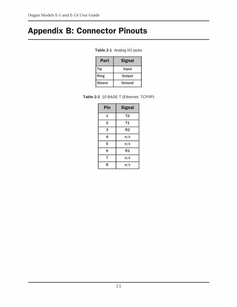
Appendix B: Connector Pinouts
Table 2-1 Analog I/O jacks
Table 2-2 10 BASE T (Ethernet, TCP/IP)
Part Signal
Tip Input
Ring Output
Sleeve Ground
Pin Signal
1 T2
2 T1
3 R2
4 n/c
5 n/c
6 R1
7 n/c
8 n/c
51


![[PROAUDIO]Ecualizacion Formulas Matematicas](https://img.pdfslide.net/doc/110x75/577cd9ab1a28ab9e78a3e6d4/proaudioecualizacion-formulas-matematicas.jpg)