Embed Size (px)
Citation preview

DANAIS TBT II FlangedType series booklet8460.1211/5--10
DN 50 to DN 1200 (2” to 48”)
Cryogenic OFFSET disc butterfly valves
Applications• LNG process / All liquefied gases.
Working conditions• Temperature: from --250 ° C to +200 ° C.• Maximum working pressure: 20 bar.• Rating: ASME B16.34 Class 150.
MaterialsSee page 2.
Design• Flanged body with raised faces (Type 6):
DN 50 (2”) to DN 1200 (48”).• Fire--safe agreement according to BS 6755 part 2
and API 6FA.• The valves meet the safety requirements of the pressure
Equipments Directive 97/23EC (PED) Appendix I for fluidsof the groups 1 and 2.
• Face to face according to ISO 5752 series 13 and EN 558.1series 13 Standards.
Connections
• PN10 / PN 16 / PN 20 in accordance with ISO 7005,• ASME B 16.5 Class 150,• ASME B16.47 Class 150 series A and B,• MSS SP 44 Class 150,• API 605,• Other drilling patterns on request.
Standard option• Lip Seal Ring for installation in any position
(> 75 ° from vertical positions)(standard for marine applications).
• Drip plate for insulation.• Electrical continuity.
Standard variants• Manual actuator MR• Pneumatic actuator ACTAIR / DYNACTAIR• Electric actuator ACTELEC• Hydraulic actuator ACTO / DYNACTO / ENNACTO• Limit switches box AMTROBOX R

DANAÏS TBT II Flanged
2
MaterialsBody KSB code
Stainless steel ASTM A 351 gr. CF 8M / 1.4408 6Disc KSB code
Stainless steel ASTM A 351 gr. CF 8M / 1.4408 with hard chromium overlay on edgeStainless steel ASTM A 351 gr. CF 8M / 1.4408 with stellite overlay on edge
66s
Operating shaft KSB code
Stainless steel A479 gr. 316L *Stainless steel A638 gr. 660Stainless steel A479 gr. XM19
6 *6f6r
Bonnet KSB code
Stainless steel ASTM A 351 gr. CF 8M / 1.4408 6Seat KSB code
Copper CU
* Caution: The working pressure is limited. Please consult us.
Kinematics
The compression of the seating disc edge onto the seat isachieved by double--eccentric kinematics.The axis of the shafts is off--set to valve axis and eccentric topipe axis.
This design eliminates the possibility of friction during operationand, as a result ensures long life service while maintaining tightshut--off characteristics.These tight shut--off characteristics comply with to the mostsevere requirements and Standards.
Axis of shaft and discin open position
Spherical diameter of disc closed
Axis of shaft and discin closed position
Travel arc ofspherical diameter
Axis of disc in closed position
Axis of disc in open position
Travel of disctowards closure
Preferential flow direction
The DANAÏS TBT II Flanged is a bi--directional valve with a preferential flow direction shown by an arrow on the body.

DANAÏS TBT II Flanged
3
Hydraulic characteristics
DN NPSFlow coefficient in full open position
ZetaDN NPSKv0 Cv0
Zeta
50 2 70 80 2.04
65 2 ½ 110 145 2.35
80 3 190 220 1.81
100 4 340 400 1.38
125 5 600 700 1.08
150 6 980 1 140 0.84
200 8 1 850 2 150 0.75
250 10 3 350 3 880 0.56
300 12 4 870 5 650 0.55
350 14 7 070 8 200 0.48
400 16 10 350 12 000 0.38
450 18 12 500 14 500 0.42
500 20 15 090 17 500 0.44
550 22 18 280 21 200 0.44
600 24 22 410 26 000 0.41
650 26 26 300 30 500 0.41
700 28 29 650 34 400 0.44
750 30 32 820 38 070 0.47
800 32 37 330 43 300 0.47
850 34 42 790 49 600 0.46
900 36 53 840 62 450 0.36
1000 40 58 290 67 600 0.47
1050 42 67 390 78 170 0.43
1200 48 80 000 92 800 0.52

DANAÏS TBT II Flanged
4
Construction
904
412.2 s
412.1 s
412.3 s
412.5 s
412.4 s
01--48 s
553
415.1 s
901.1
554.1
n 41--2
13--21
213
512
902
415.2
310.2 n
901.4
550
72.3
144 l
50.5
932
901.5
543.2
310.3 n
210
559
310.1 sn
72.2
901.2
543.1
920
930.4
930.3
930.1
970
100
561.1554.2
Detail D
Detail D
Detail A Detail A
DN 450/18”to DN 1200/48”
Detail C
Detail C
Detail B
81--2 l
Detail B
553.2
930.5
901.6
l Spare parts included in the seat gasket kits Spare parts included in the shaft sealing kitn Spare parts included in the bearing kit

DANAÏS TBT II Flanged
5
Parts listItem Designation Materials
01--48 Sealing packing Expanded graphite100 Body Stainless steel A351 gr CF8M (1.4408)13--21 Extension Stainless steel A351 gr CF8M (1.4408)144 Seat Copper210 Shaft Stainless steel A479 gr. 316L213 Operating shaft Stainless steel A479 gr. 316L or A638 gr. 660 (*)
or A479 gr. XM19310.1 Self lubricating strip Stainless steel + PTFE310.2 Self lubricating strip Stainless steel + PTFE310.3 Self lubricating strip Stainless steel + PTFE41--2 Static joint Nickel412.1 O--ring HC Nitrile(**)
412.2 O--ring HC Nitrile(**)
412.3 O--ring HC Nitrile(**)
412.4 O--ring HC Nitrile(**)
412.5 O--ring HC Nitrile(**)
415.1 Lip seal ring PTFE + Elgiloy415.2 Lip seal ring (Standard for marine applications)
(Optional for others applications)
PTFE + Elgiloy
50--5 Reaction ring A638 gr. 660512 Adjusting ring Z 3 CND 17--11--02 / 316L543.1 Spacer bush Z 3 CND 17--11--02 / 316L543.2 Spacer bush Z 3 CND 17--11--02 / 316L550 Disc Stainless steel A351 gr CF8M (1.4408) with hard chromium
or stellite overlay on edge553 Thrust insert Z3 CND 17--11--02 / 316L553.2 Thrust Stainless steel 316L554.1 Washer Stainless steel554.2 Plain washer Stainless steel559 Gasket holder Z3 CND 17--11--02 / 316L561.1 Grooved pin Z3 CND 17--12--02 / 316L72--2 Centering flange Z3 CND 17--11--01 / 316L72--3 Tightening flange Z3 CND 17--11--01 / 316L81--2 Wire Z3 CN 18--09901.1 Hexagon head screw A4--80 Stainless steel901.2 Hexagon head screw A4--80 Stainless steel901.4 Hexagon head screw A4--80 Stainless steel901.5 Hexagon head screw A4--80 Stainless steel901.6 Hexagon head screw A4--70 Stainless steel902 Stud A320 gr. B8 M cl. 2904 Socket screw A4--70 Stainless steel920 Hexagon nut A 194 gr. 8 M930.1 Retainer Stainless steel 316 or equivalent930.3 Retainer Stainless steel 316 or equivalent930.3 Nut lock Stainless steel 316930.4 Nut lock Stainless steel 316 or equivalent930.5 Retainer (DN ≥ 700) or wire (DN 450 to 650) Stainless steel 316 or equivalent932 Inner ring Stainless steel 316 or equivalent970 Identity plate Stainless steel 316 or equivalent
(*) For DN550, only A638 gr. 660 or A479 gr. XM19 available(**) HC Nitrile: Epichlorohydrin for ambient temperature below minus 25 ° C.
DANAÏS TBT II Flanged
6
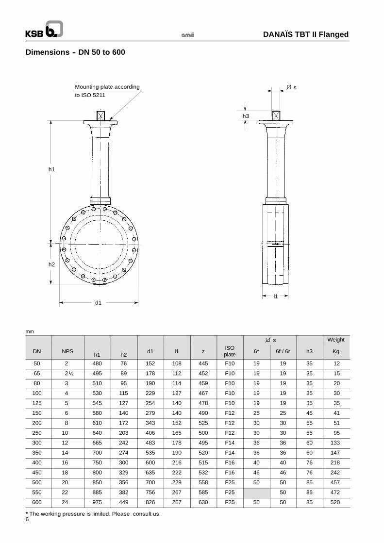
Dimensions -- DN 50 to 600
h1
h2
d1
h3
sMounting plate accordingto ISO 5211
l1
mm
s Weight
DN NPSh1 h2
d1 l1 zISOplate 6* 6f / 6r h3 Kg
50 2 480 76 152 108 445 F10 19 19 35 12
65 2½ 495 89 178 112 452 F10 19 19 35 15
80 3 510 95 190 114 459 F10 19 19 35 20
100 4 530 115 229 127 467 F10 19 19 35 30
125 5 545 127 254 140 478 F10 19 19 35 35
150 6 580 140 279 140 490 F12 25 25 45 41
200 8 610 172 343 152 525 F12 30 30 55 51
250 10 640 203 406 165 500 F12 30 30 55 95
300 12 665 242 483 178 495 F14 36 36 60 133
350 14 700 274 535 190 520 F14 36 36 60 147
400 16 750 300 600 216 515 F16 40 40 76 218
450 18 800 329 635 222 532 F16 46 46 76 242
500 20 850 356 700 229 558 F25 50 50 85 457
550 22 885 382 756 267 585 F25 50 85 472
600 24 975 449 826 267 630 F25 55 50 85 520
* The working pressure is limited. Please consult us.
DANAÏS TBT II Flanged
7
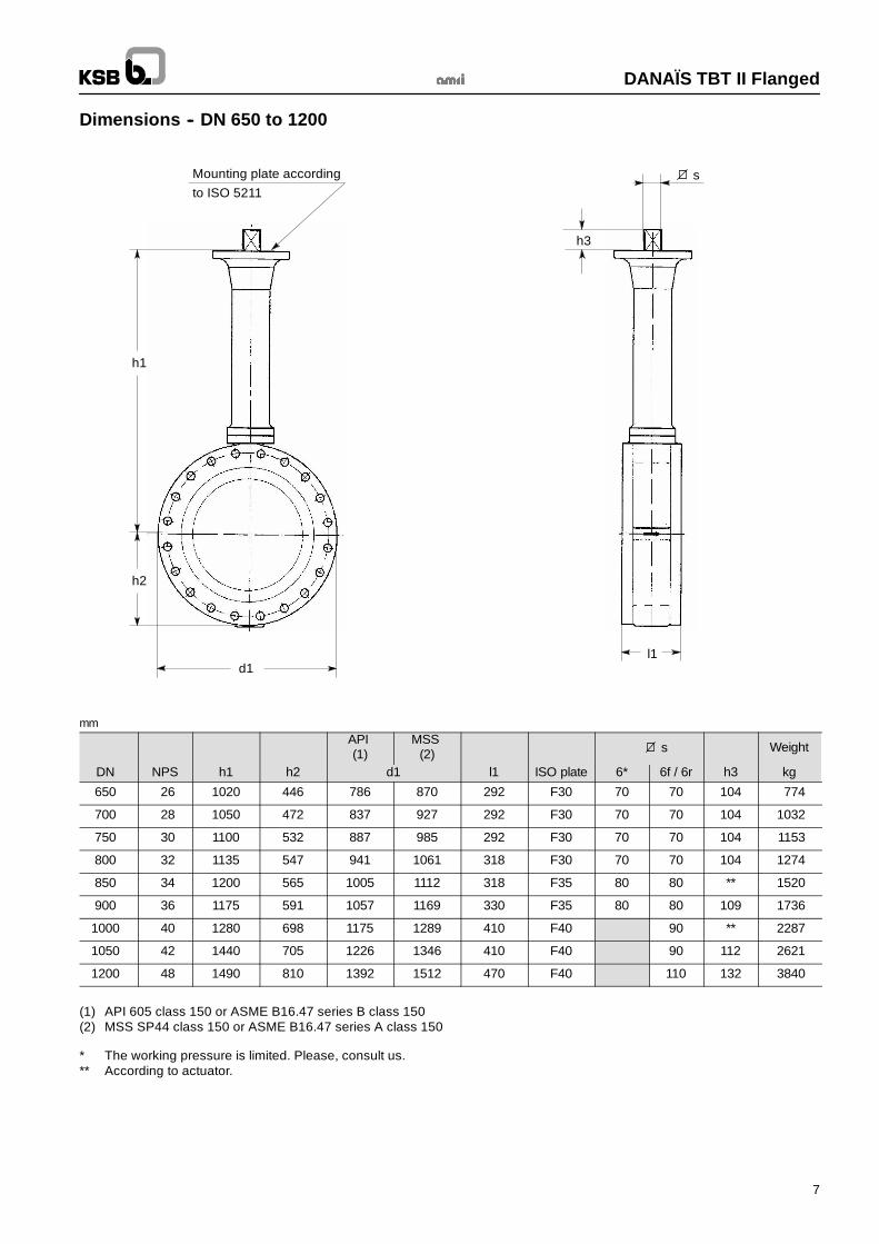
Dimensions -- DN 650 to 1200
h1
h2
d1
h3
sMounting plate accordingto ISO 5211
l1
mmAPI(1)
MSS(2) s Weight
DN NPS h1 h2 d1 l1 ISO plate 6* 6f / 6r h3 kg
650 26 1020 446 786 870 292 F30 70 70 104 774
700 28 1050 472 837 927 292 F30 70 70 104 1032
750 30 1100 532 887 985 292 F30 70 70 104 1153
800 32 1135 547 941 1061 318 F30 70 70 104 1274
850 34 1200 565 1005 1112 318 F35 80 80 ** 1520
900 36 1175 591 1057 1169 330 F35 80 80 109 1736
1000 40 1280 698 1175 1289 410 F40 90 ** 2287
1050 42 1440 705 1226 1346 410 F40 90 112 2621
1200 48 1490 810 1392 1512 470 F40 110 132 3840
(1) API 605 class 150 or ASME B16.47 series B class 150(2) MSS SP44 class 150 or ASME B16.47 series A class 150
* The working pressure is limited. Please, consult us.** According to actuator.

DANAÏS TBT II Flanged
8
Dimensions for flange gasket definition
In order to ensure a correct connection, the dimensions of flange gaskets must be compatible with the dimensions mentionned inthe table below.Connection according to ASME B16.5 class 150 and ASME B16.47 class 150 série A.
ØA
ØF
Ch to 45° Ch to 45°
ØR
F
ØJ
NB: We do not supplythe gasket
DN NPS Ø A±0.50
Ø F--10 Ø J
80 3 94 ,5 90 ,5 104 ,5
100 4 128 ,5 127 138 ,5
150 6 177 176 187
200 8 230 228 240
250 10 278 279 286
300 12 326 330 337
350 14 376 ,5 377 387
400 16 426 ,5 432 439
450 18 490 ,5 477 499
500 20 530 ,5 528 541
550 22 581 587 594
600 24 627 638 647
650 26 673 679 690
700 28 707 713 725
750 30 760 ,5 760 773
800 32 813 816 ,5 828 ,5
850 34
900 36 918 924 936
1000 40
1050 42 1066 1054 1078
1200 48 1184 1176 1196
Please consult us
Flange facing finish
Serrated spiral finish according to ASME B16.5 class 150 or ASME B16.47 class 150 série A.Standard:Stock finish (Ra 6,3 to Ra 12,5)Optional: Smooth finish (Ra 3,2 and Ra 6,3)

DANAÏS TBT II Flanged
9
Option
Drip Plate for insulation

DANAÏS TBT II Flanged
10
Standard variants
ACTAIR / DYNACTAIR pneumatic actuatorwith manual override
ACTO hydraulic actuator
MR manual reducer
ENNACTO hydraulic actuator

DANAÏS TBT II Flanged
11
Notes

KSB S.A.S4, allée des Barbanniers • 92635 Gennevilliers Cedex (France)Tel. : +33 1 41 47 75 00 • Fax : +33 1 41 47 75 10 • www.ksb.com
DANAÏS TBT II Flanged
03.1
0.11
Thi
sle
afle
tis
notc
ontr
actu
alan
dm
aybe
amen
ded
with
outn
otic
e.84
60.1
211/
5--1
0


![VENTS KSB EC - folheto187 VENTS. Industrial and commercial ventilation 02201 Point Power [W] KSB 100 EC KSB 125 EC KSB 150 EC KSB 160 EC KSB 200 EC KSB 250 EC KSB 315 EC 1 83 83 83](https://img.pdfslide.net/doc/110x75/5e921ded45cff356a6235202/vents-ksb-ec-folheto-187-vents-industrial-and-commercial-ventilation-02201-point.jpg)