Embed Size (px)
Citation preview
1
DanfossGX™ 850MManual
NA
2
1: User Manual System overview . . . . . . . . . . . . . . . . . . . . . . . . . . . . . . . . . . . . . . . . . . . . . . . . 3
General use . . . . . . . . . . . . . . . . . . . . . . . . . . . . . . . . . . . . . . . . . . . . . . . . . . . 5
Buttons . . . . . . . . . . . . . . . . . . . . . . . . . . . . . . . . . . . . . . . . . . . . . . . . . 5
Display. . . . . . . . . . . . . . . . . . . . . . . . . . . . . . . . . . . . . . . . . . . . . . . . . . 5
Menu system. . . . . . . . . . . . . . . . . . . . . . . . . . . . . . . . . . . . . . . . . . . . . . 6
Possible alarms during operation
Clogged drain . . . . . . . . . . . . . . . . . . . . . . . . . . . . . . . . . . . . . . . . . . . . . 7
Missing sensor . . . . . . . . . . . . . . . . . . . . . . . . . . . . . . . . . . . . . . . . . . . . . 7
New added sensor . . . . . . . . . . . . . . . . . . . . . . . . . . . . . . . . . . . . . . . . . . 7
Sensor malfunction. . . . . . . . . . . . . . . . . . . . . . . . . . . . . . . . . . . . . . . . . . 7
Changing parameters and performance of systems. . . . . . . . . . . . . . . . . . . . . . . . . . 8
Roof system . . . . . . . . . . . . . . . . . . . . . . . . . . . . . . . . . . . . . . . . . . . . . . 8
Ground system . . . . . . . . . . . . . . . . . . . . . . . . . . . . . . . . . . . . . . . . . . . . 9
2: Installer Manual System overview . . . . . . . . . . . . . . . . . . . . . . . . . . . . . . . . . . . . . . . . . . . . . . . 10
Placement . . . . . . . . . . . . . . . . . . . . . . . . . . . . . . . . . . . . . . . . . . . . . . . . . . . 11
Connection steps for system . . . . . . . . . . . . . . . . . . . . . . . . . . . . . . . . . . . . . . . 11
Installation steps for system/systems . . . . . . . . . . . . . . . . . . . . . . . . . . . . . . . . . . 15
General . . . . . . . . . . . . . . . . . . . . . . . . . . . . . . . . . . . . . . . . . . . . . . . . 15
Installation of roof system . . . . . . . . . . . . . . . . . . . . . . . . . . . . . . . . . . . . 16
Installation of ground system . . . . . . . . . . . . . . . . . . . . . . . . . . . . . . . . . . 17
Installation of combi system . . . . . . . . . . . . . . . . . . . . . . . . . . . . . . . . . . . 18
Installation of dual system . . . . . . . . . . . . . . . . . . . . . . . . . . . . . . . . . . . . 20
Modifi cation of system(s) . . . . . . . . . . . . . . . . . . . . . . . . . . . . . . . . . . . . . . . . . 22
3: Technical Specifi cation Technical data . . . . . . . . . . . . . . . . . . . . . . . . . . . . . . . . . . . . . . . . . . . . . . . . 25
Factory settings (Roof system) . . . . . . . . . . . . . . . . . . . . . . . . . . . . . . . . . . . . . . 26
Factory settings (Ground system) . . . . . . . . . . . . . . . . . . . . . . . . . . . . . . . . . . . . 26
4: Appendix . . . . . . . . . . . . . . . . . . . . . . . . . . . . . . . . . . . . . . . . . . . . . : A: Menu system. . . . . . . . . . . . . . . . . . . . . . . . . . . . . . . . . . . . . . . . . . . . . . . . 27
B: How it works . . . . . . . . . . . . . . . . . . . . . . . . . . . . . . . . . . . . . . . . . . . . . . . . 32
Roof system . . . . . . . . . . . . . . . . . . . . . . . . . . . . . . . . . . . . . . . . . . . . . 32
Ground system . . . . . . . . . . . . . . . . . . . . . . . . . . . . . . . . . . . . . . . . . . . 33
Security and energy consumption . . . . . . . . . . . . . . . . . . . . . . . . . . . . . . . 34
C: PSU and feeder cable . . . . . . . . . . . . . . . . . . . . . . . . . . . . . . . . . . . . . . . . . . 35
Ground system . . . . . . . . . . . . . . . . . . . . . . . . . . . . . . . . . . . . . . . . . . . 35
Roof system . . . . . . . . . . . . . . . . . . . . . . . . . . . . . . . . . . . . . . . . . . . . . 35
Table of Contents
User Manual
3
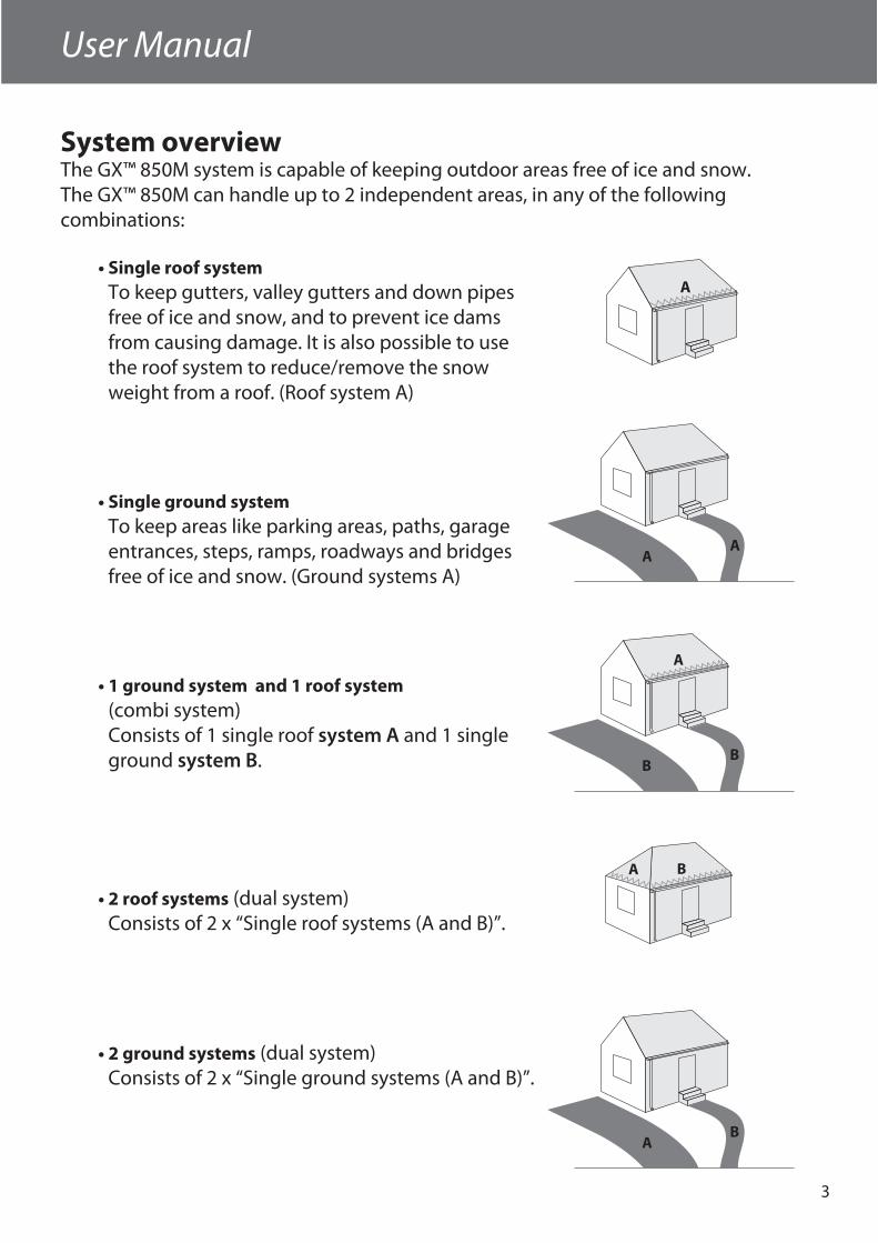
System overviewThe GX™ 850M system is capable of keeping outdoor areas free of ice and snow. The GX™ 850M can handle up to 2 independent areas, in any of the following combinations:
• Single roof systemTo keep gutters, valley gutters and down pipes free of ice and snow, and to prevent ice dams from causing damage. It is also possible to use the roof system to reduce/remove the snow weight from a roof. (Roof system A)
• Single ground systemTo keep areas like parking areas, paths, garage entrances, steps, ramps, roadways and bridges free of ice and snow. (Ground systems A)
• 1 ground system and 1 roof system (combi system)Consists of 1 single roof system A and 1 single ground system B.
• 2 roof systems (dual system)Consists of 2 x “Single roof systems (A and B)”.
• 2 ground systems (dual system)Consists of 2 x “Single ground systems (A and B)”.
A
AA
A
BB
BA
AB

4
User Manual
When more than 1 area is controlled by the GX™ 850M system, it is also possible to prioritize the areas. Prioritizing makes it possible to operate 2 areas, even if the required power for 2 areas is not present.
The GX™ 850M is fully automatic and operated digitally by means of the intelligent sen-sors located in the heated terrain. Each sensor measures both temperature and mois-ture, and the system turns the heating elements on and off based on these readings. By combining moisture and temperature readings, the system is able to save around 75% energy compared to systems which only measure temperature readings. The digital sensors used for the GX™ 850M also provide the most exact readings when compared with corresponding analogue systems. The result is optimum functionality and low energy consumption.
A typical installation consists of: • Controller unit (only one)
This is the device which, based on the measure-ments from the sensors, decides when to heat the connected area(s).
• Power supply (one or more)The power supply delivers power to the controller unit and the connected sensors.
• Ground sensor (one or more)At least 1 ground sensor is needed for each ground area, but to get the best performance of a system, 2 or more sensors are recommended.For more information please refer to the sensor manual.
• Roof sensor (one or more)At least 1 roof sensor is needed for each roof area, but for complex roof constructions, 2 or more sen-sors are recommended.For more information please refer to the sensor manual.
For more information about the ice and snow melting function of the GX™ 850M, please refer to: Appendix B: “How it works”.
User Manual
5
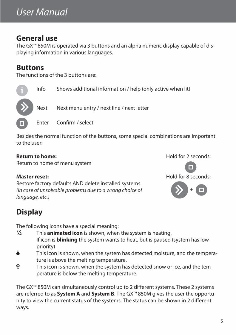
General useThe GX™ 850M is operated via 3 buttons and an alpha numeric display capable of dis-playing information in various languages.
ButtonsThe functions of the 3 buttons are:
Info Shows additional information / help (only active when lit)
Next Next menu entry / next line / next letter
Enter Confi rm / select
Besides the normal function of the buttons, some special combinations are important to the user:
Return to home: Hold for 2 seconds:Return to home of menu system
Master reset: Hold for 8 seconds:Restore factory defaults AND delete installed systems. (In case of unsolvable problems due to a wrong choice of language, etc.)
Display
The following icons have a special meaning: This animated icon is shown, when the system is heating. If icon is blinking the system wants to heat, but is paused (system has low priority) This icon is shown, when the system has detected moisture, and the tempera-
ture is above the melting temperature. This icon is shown, when the system has detected snow or ice, and the tem-
perature is below the melting temperature.
The GX™ 850M can simultaneously control up to 2 diff erent systems. These 2 systems are referred to as System A and System B. The GX™ 850M gives the user the opportu-nity to view the current status of the systems. The status can be shown in 2 diff erent ways.
+
6
User Manual
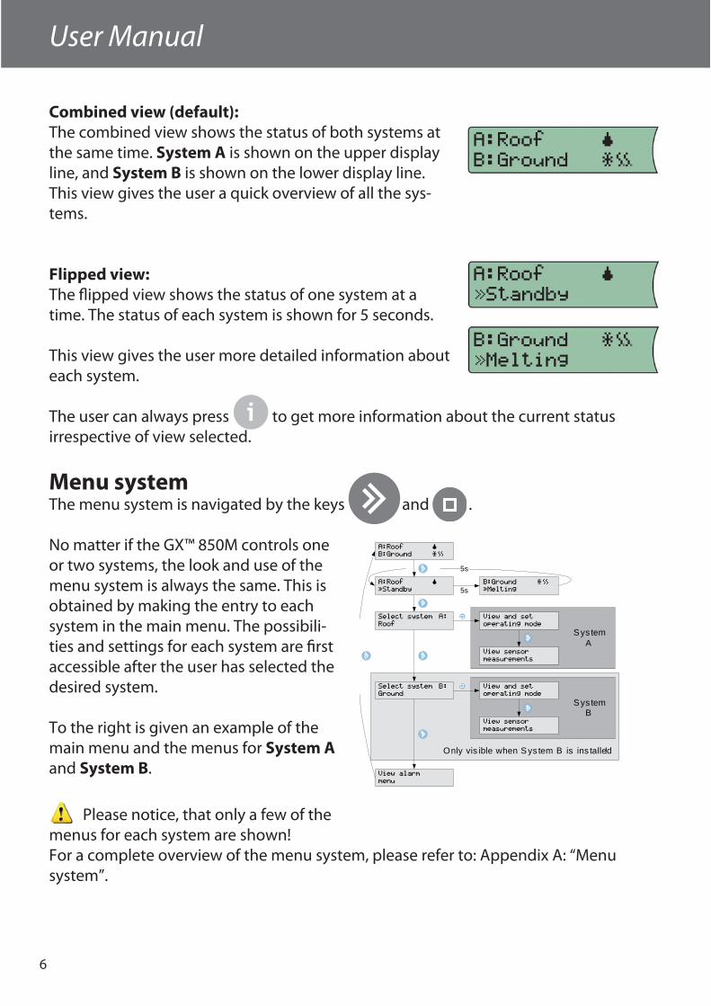
Combined view (default):The combined view shows the status of both systems at the same time. System A is shown on the upper display line, and System B is shown on the lower display line.This view gives the user a quick overview of all the sys-tems.
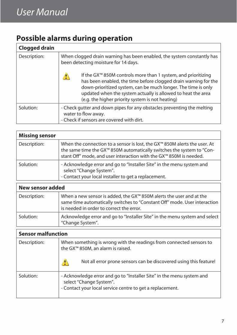
Flipped view:The fl ipped view shows the status of one system at a time. The status of each system is shown for 5 seconds.
This view gives the user more detailed information about each system.
The user can always press to get more information about the current status irrespective of view selected.
Menu systemThe menu system is navigated by the keys and .
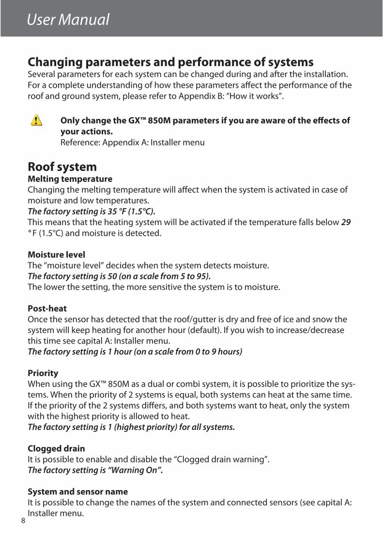
No matter if the GX™ 850M controls one or two systems, the look and use of the menu system is always the same. This is obtained by making the entry to each system in the main menu. The possibili-ties and settings for each system are fi rst accessible after the user has selected the desired system.
To the right is given an example of the main menu and the menus for System A and System B.
Please notice, that only a few of the menus for each system are shown!For a complete overview of the menu system, please refer to: Appendix A: “Menu system”.
Sys tem B
Sys tem A
A:Roof ˜
ÚStandby
B:Ground ¯ˆı
ÚMelting
Select system A:
Roof
Select system B:
Ground
View alarm
menu
5s
A:Roof ˜
B:Ground ¯ˆı
5s
View and set
operating mode
View sensor
measurements
View and set
operating mode
View sensor
measurements
Only vis ible when Sys tem B is ins talled!
User Manual
7
Possible alarms during operationClogged drain
Description: When clogged drain warning has been enabled, the system constantly has been detecting moisture for 14 days.
If the GX™ 850M controls more than 1 system, and prioritizing has been enabled, the time before clogged drain warning for the down-prioritized system, can be much longer. The time is only updated when the system actually is allowed to heat the area (e.g. the higher priority system is not heating)
Solution: - Check gutter and down pipes for any obstacles preventing the meltingwater to fl ow away.
- Check if sensors are covered with dirt.
Missing sensor
Description: When the connection to a sensor is lost, the GX™ 850M alerts the user. At the same time the GX™ 850M automatically switches the system to “Con-stant Off ” mode, and user interaction with the GX™ 850M is needed.
Solution: - Acknowledge error and go to “Installer Site” in the menu system and select “Change System”.
- Contact your local installer to get a replacement.
New sensor added
Description: When a new sensor is added, the GX™ 850M alerts the user and at the same time automatically switches to “Constant Off ” mode. User interaction is needed in order to correct the error.
Solution: Acknowledge error and go to “Installer Site” in the menu system and select “Change System”.
Sensor malfunction
Description: When something is wrong with the readings from connected sensors to the GX™ 850M, an alarm is raised.
Not all error prone sensors can be discovered using this feature!
Solution: - Acknowledge error and go to “Installer Site” in the menu system and select “Change System”.
- Contact your local service centre to get a replacement.
8
User Manual
Changing parameters and performance of systemsSeveral parameters for each system can be changed during and after the installation. For a complete understanding of how these parameters aff ect the performance of the roof and ground system, please refer to Appendix B: “How it works”.
Only change the GX™ 850M parameters if you are aware of the eff ects of your actions.Reference: Appendix A: Installer menu
Roof systemMelting temperatureChanging the melting temperature will aff ect when the system is activated in case of moisture and low temperatures.The factory setting is 35 °F (1.5°C).This means that the heating system will be activated if the temperature falls below 29° F (1.5°C) and moisture is detected.
Moisture levelThe “moisture level” decides when the system detects moisture.The factory setting is 50 (on a scale from 5 to 95).The lower the setting, the more sensitive the system is to moisture.
Post-heatOnce the sensor has detected that the roof/gutter is dry and free of ice and snow the system will keep heating for another hour (default). If you wish to increase/decrease this time see capital A: Installer menu.The factory setting is 1 hour (on a scale from 0 to 9 hours)
PriorityWhen using the GX™ 850M as a dual or combi system, it is possible to prioritize the sys-tems. When the priority of 2 systems is equal, both systems can heat at the same time. If the priority of the 2 systems diff ers, and both systems want to heat, only the system with the highest priority is allowed to heat.The factory setting is 1 (highest priority) for all systems.
Clogged drainIt is possible to enable and disable the “Clogged drain warning”.The factory setting is “Warning On”.
System and sensor nameIt is possible to change the names of the system and connected sensors (see capital A: Installer menu.
User Manual
9
Ground systemMelting temperatureChanging the melting temperature will aff ect when the system is activated in case of moisture and low temperatures.The factory setting is 39°F (4°C).This means that the heating system will be activated if the temperature falls below 4°C and moisture is detected.
Standby temperature (maintained ground temperature)The higher the standby temperature the faster the system will be able to melt ice and snow.On the other hand the higher the standby temperature the higher the running costs. So, determining the standby temperature is a trade-off between fast melting or low running costs. The factory setting is 27°F (-3 C°).
Moisture levelThe “moisture level” decides when the system detects moisture.The factory setting is 50 (on a scale from 5 to 95).The lower the setting, the more sensitive the system is to moisture.
Post-heatOnce the sensor has detected that the roof/gutter is dry and free of ice and snow the system will keep heating for another hour (default). If you wish to increase/decrease this time see capital A: Installer menu.The factory setting is 1 hour (on a scale from 0 to 9 hours)
PriorityWhen using the GX™ 850M as a dual or combi system, it is possible to prioritize the sys-tems. When the priority of 2 systems is equal, both systems can heat at the same time. If the priority of the 2 systems diff ers, and both systems want to heat, only the system with the highest priority is allowed to heat.The factory setting is 1 (highest priority) for all systems.
Clogged drainIt is possible to enable and disable the “Clogged drain warning”.The factory setting is “Warning On”.
System and sensor nameIt is possible to change the names of the system and connected sensors.
10
User Manual
Installer Manual
System overviewThe GX™ 850M can handle up to 2 independent areas, in any of the following combinations:
• Single roof system(1 system, 1-4 roof sensors)
• Single ground system(1 system, 1-4 roof sensors)
• 1 ground system and 1 roof system (combi system)(2 systems, 2-4 sensors total, minimum 1 sensor per system)
• 2 roof systems (dual system)(2 systems, 2-4 sensors total, minimum 1 sensor per system)
• 2 ground systems (dual system)(2 systems, 2-4 sensors total, minimum 1 sensor per system)
When more than 1 area is controlled by the GX™ 850M system, it is also possible to prioritize the areas. Prioritizing makes it possible to operate 2 areas, even if the needed power for 2 areas is not present.
A typical ice and snow melting system consists of:• GX™ 850M
• Only 1 GX™ 850M is allowed on the Devibus™• Power supply
• More power supplies can be connected in parallel (if needed)• Be aware of maximum number of sensors on each power supply(Refer to Technical Specifi cation for power demand of sensors)
• Ground and/or roof sensor(s)• Be aware of maximum number and cable length of sensors on each power supply
(Refer to sensor manual for a more detailed description)
Installer Manual
User Manual
11
PlacementThe GX™ 850M and power supply are designed for DIN rail mounting. When mounting please be aware of the following conditions:
The GX™ 850M is designed and approved to operate in the temperature range 14°F ( -10°C) to 104°F (40°C).
The GX™ 850M is only NEMA 1 protected, thus not water resistant.
The installer must ensure proper enclosure of the GX™ 850M according to national standards (electrical safety).
Connection steps for system Only authorized personnel is allowed to install the GX™ 850M.
When wiring up the GX™ 850M and sensors, please be aware of the following conditions:
When the GX™ 850M is used in a dual system confi guration, it is preferable that each sensor bus (Devibus™) can be connected and disconnected via switches. During the installation of a dual system, each system must be con-nected one at a time.
Be aware of maximum allowable power drain from power supply to sensors.
Below is shown the recommended order of the installation. Please refer to Figure A for connection of GX™ 850M and refer to Figure B-G for a guideline to connect the heating elements to GX™ 850M.
1. Connect heating cables to the GX™ 850M• Please notice that a single system ALWAYS uses the System A output relay• When using external power relay, please refer to the connection diagrams.
2. Connect the power supply to the GX™ 850M• Do not connect the power supply to mains yet
3. Connect sensors to the Devibus™• When used as a dual system, only the sensors for System A can be connected. For
connection of System B please refer to chapter: “Installation of dual system”.4. Connect the power supply to mains.
Installer Manual
12
Installer Manual
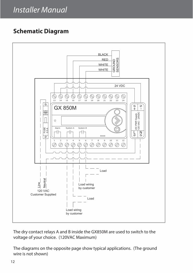
Schematic Diagram
The dry contact relays A and B inside the GX850M are used to switch to the voltage of your choice. (120VAC Maximum)
The diagrams on the opposite page show typical applications. (The ground wire is not shown)
Installer Manual
13
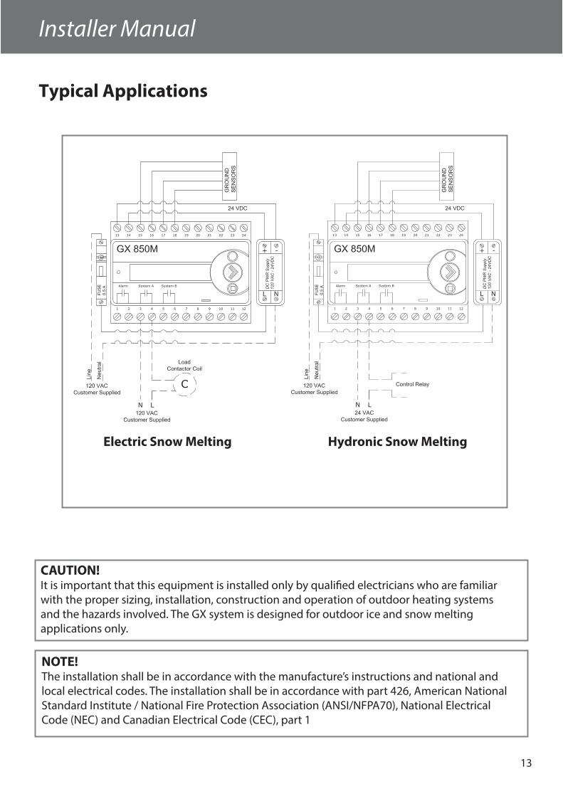
Typical Applications
CAUTION!It is important that this equipment is installed only by qualifi ed electricians who are familiarwith the proper sizing, installation, construction and operation of outdoor heating systemsand the hazards involved. The GX system is designed for outdoor ice and snow meltingapplications only.
NOTE!The installation shall be in accordance with the manufacture’s instructions and national andlocal electrical codes. The installation shall be in accordance with part 426, American National Standard Institute / National Fire Protection Association (ANSI/NFPA70), National ElectricalCode (NEC) and Canadian Electrical Code (CEC), part 1
Electric Snow Melting Hydronic Snow Melting

14
Installer Manual
Part Numbers
Part # Description Voltage
088L3415 GX850M Automatic Control Panel 120V
Part # Description
088L3051 Ground Sensors (Two per Package)
088L3052 Roof Sensor
GX Snow Melting Controls
GX Snow Melting Accessories
GX850M Automatic Control Panel
Roof SensorGround Sensor
Installer Manual
15
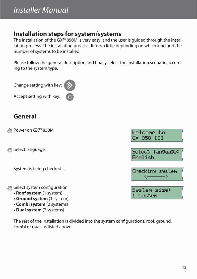
Installation steps for system/systemsThe installation of the GX™ 850M is very easy, and the user is guided through the instal-lation process. The installation process diff ers a little depending on which kind and the number of systems to be installed.
Please follow the general description and fi nally select the installation scenario accord-ing to the system type.
Change setting with key:
Accept setting with key:
General
Power on GX™ 850M
Select language
System is being checked…
Select system confi guration• Roof system (1 system)• Ground system (1 system)• Combi system (2 systems)• Dual system (2 systems)
The rest of the installation is divided into the system confi gurations; roof, ground, combi or dual, as listed above.
16
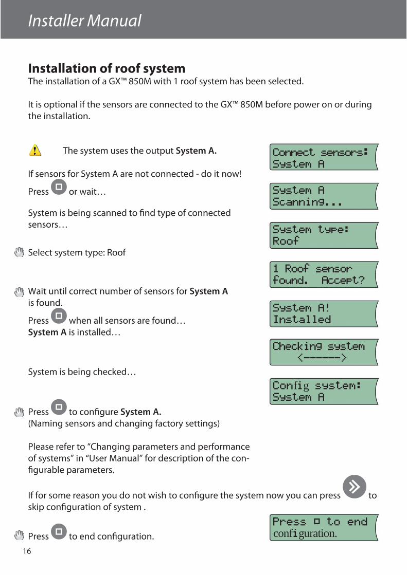
Installation of roof systemThe installation of a GX™ 850M with 1 roof system has been selected.
It is optional if the sensors are connected to the GX™ 850M before power on or during the installation.
The system uses the output System A.
If sensors for System A are not connected - do it now!
Press or wait…
System is being scanned to fi nd type of connectedsensors…
Select system type: Roof
Wait until correct number of sensors for System Ais found.
Press when all sensors are found…System A is installed…
System is being checked…
Press to confi gure System A.(Naming sensors and changing factory settings)
Please refer to “Changing parameters and performance of systems” in “User Manual” for description of the con-fi gurable parameters.
If for some reason you do not wish to confi gure the system now you can press to skip confi guration of system .
Press to end confi guration.
fg
confguration.
Installer Manual
17
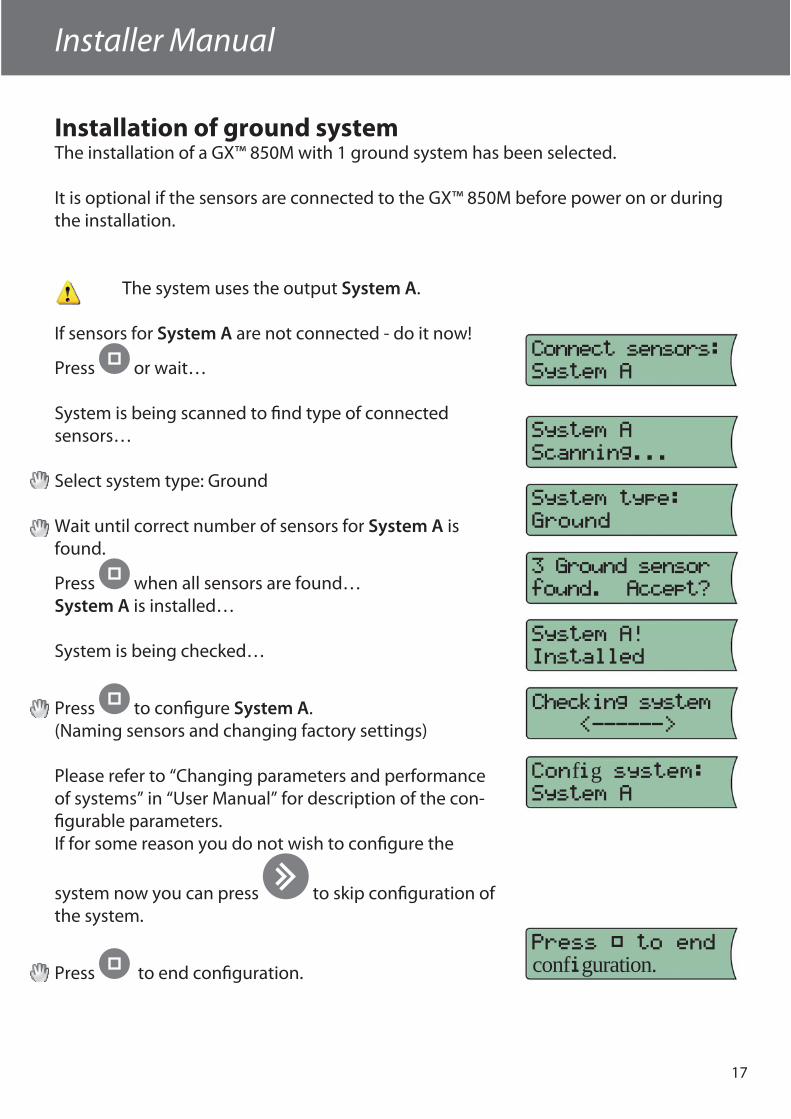
Installation of ground systemThe installation of a GX™ 850M with 1 ground system has been selected.
It is optional if the sensors are connected to the GX™ 850M before power on or during the installation.
The system uses the output System A.
If sensors for System A are not connected - do it now!
Press or wait…
System is being scanned to fi nd type of connectedsensors…
Select system type: Ground
Wait until correct number of sensors for System A isfound.
Press when all sensors are found…System A is installed…
System is being checked…
Press to confi gure System A.(Naming sensors and changing factory settings)
Please refer to “Changing parameters and performance of systems” in “User Manual” for description of the con-fi gurable parameters.If for some reason you do not wish to confi gure the
system now you can press to skip confi guration of the system.
Press to end confi guration.
fg
confguration.
Installer Manual
18
Installer Manual
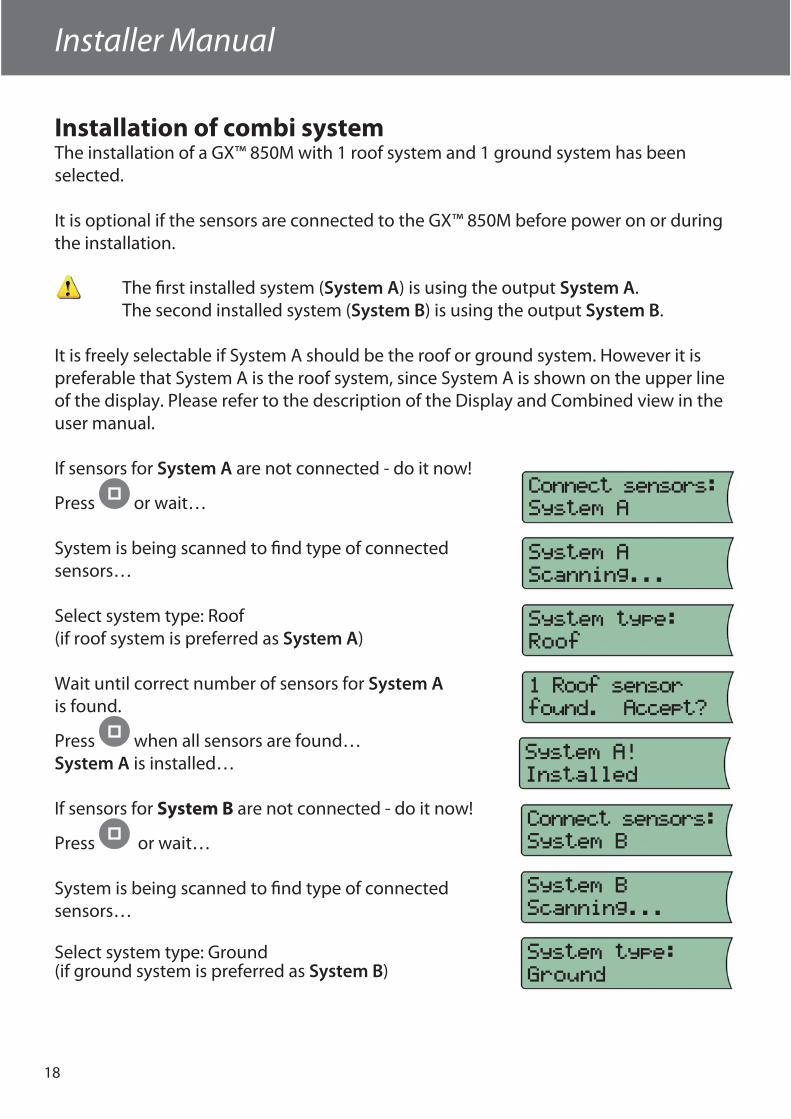
Installation of combi systemThe installation of a GX™ 850M with 1 roof system and 1 ground system has been selected.
It is optional if the sensors are connected to the GX™ 850M before power on or during the installation.
The fi rst installed system (System A) is using the output System A.The second installed system (System B) is using the output System B.
It is freely selectable if System A should be the roof or ground system. However it is preferable that System A is the roof system, since System A is shown on the upper line of the display. Please refer to the description of the Display and Combined view in the user manual.
If sensors for System A are not connected - do it now!
Press or wait…
System is being scanned to fi nd type of connectedsensors…
Select system type: Roof (if roof system is preferred as System A)
Wait until correct number of sensors for System Ais found.
Press when all sensors are found…System A is installed…
If sensors for System B are not connected - do it now!
Press or wait…
System is being scanned to fi nd type of connected sensors…
Select system type: Ground(if ground system is preferred as System B)
Installer Manual
19
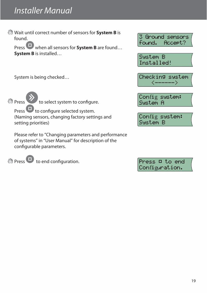
Wait until correct number of sensors for System B is found.
Press when all sensors for System B are found…System B is installed…
System is being checked…
Press to select system to confi gure.
Press to confi gure selected system. (Naming sensors, changing factory settings and setting priorities)
Please refer to “Changing parameters and performance of systems” in “User Manual” for description of the confi gurable parameters.
Press to end confi guration.
fg
fg
fg
20
Installer Manual
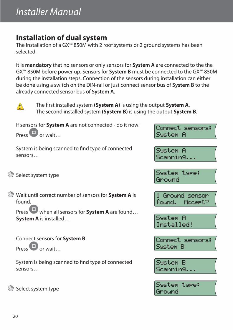
Installation of dual systemThe installation of a GX™ 850M with 2 roof systems or 2 ground systems has been selected.
It is mandatory that no sensors or only sensors for System A are connected to the the GX™ 850M before power up. Sensors for System B must be connected to the GX™ 850M during the installation steps. Connection of the sensors during installation can either be done using a switch on the DIN-rail or just connect sensor bus of System B to the already connected sensor bus of System A.
The fi rst installed system (System A) is using the output System A. The second installed system (System B) is using the output System B.
If sensors for System A are not connected - do it now!
Press or wait…
System is being scanned to fi nd type of connectedsensors…
Select system type
Wait until correct number of sensors for System A isfound.
Press when all sensors for System A are found…System A is installed…
Connect sensors for System B.
Press or wait…
System is being scanned to fi nd type of connectedsensors…
Select system type
Installer Manual
21
fg
fg
fg
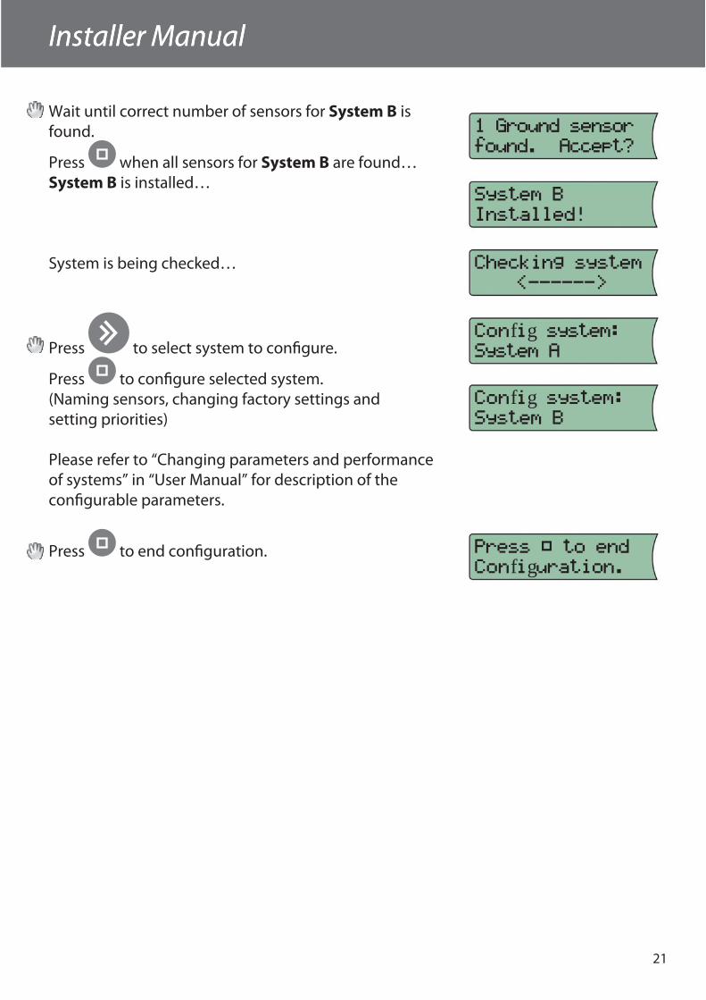
Wait until correct number of sensors for System B is found.
Press when all sensors for System B are found…System B is installed…
System is being checked…
Press to select system to confi gure.
Press to confi gure selected system. (Naming sensors, changing factory settings and setting priorities)
Please refer to “Changing parameters and performance of systems” in “User Manual” for description of the confi gurable parameters.
Press to end confi guration.
Installer Manual
22
Installer Manual
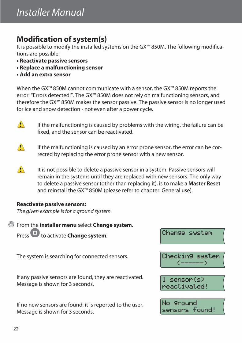
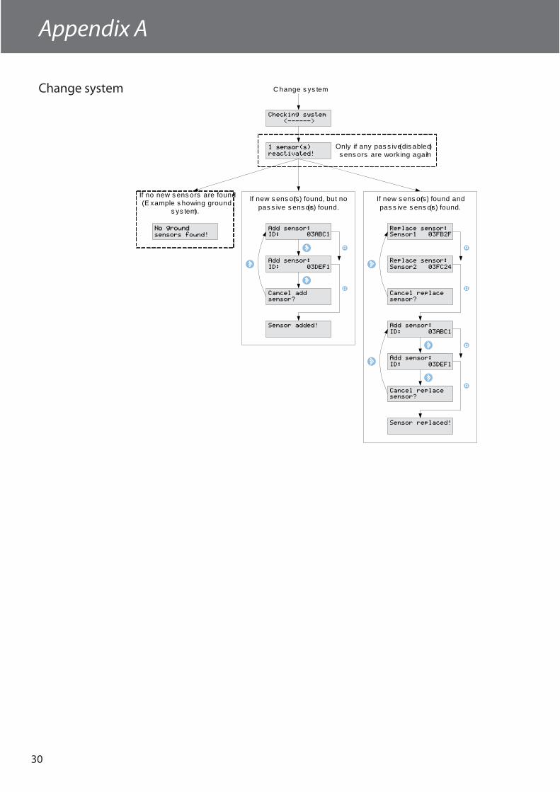
Modifi cation of system(s)It is possible to modify the installed systems on the GX™ 850M. The following modifi ca-tions are possible:• Reactivate passive sensors• Replace a malfunctioning sensor• Add an extra sensor
When the GX™ 850M cannot communicate with a sensor, the GX™ 850M reports the error: “Errors detected!”. The GX™ 850M does not rely on malfunctioning sensors, and therefore the GX™ 850M makes the sensor passive. The passive sensor is no longer used for ice and snow detection - not even after a power cycle.
If the malfunctioning is caused by problems with the wiring, the failure can be fi xed, and the sensor can be reactivated.
If the malfunctioning is caused by an error prone sensor, the error can be cor-rected by replacing the error prone sensor with a new sensor.
It is not possible to delete a passive sensor in a system. Passive sensors will remain in the systems until they are replaced with new sensors. The only way to delete a passive sensor (other than replacing it), is to make a Master Reset and reinstall the GX™ 850M (please refer to chapter: General use).
Reactivate passive sensors:The given example is for a ground system.
From the installer menu select Change system.
Press to activate Change system.
The system is searching for connected sensors.
If any passive sensors are found, they are reactivated. Message is shown for 3 seconds.
If no new sensors are found, it is reported to the user. Message is shown for 3 seconds.
Installer Manual
23
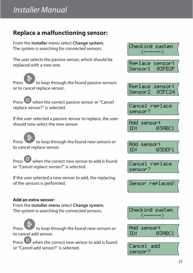
Replace a malfunctioning sensor:
From the installer menu select Change system.The system is searching for connected sensors.
The user selects the passive sensor, which should be replaced with a new one.
Press to loop through the found passive sensors or to cancel replace sensor.
Press when the correct passive sensor or “Cancel replace sensor?” is selected.
If the user selected a passive sensor to replace, the user should now select the new sensor.
Press to loop through the found new sensors or to cancel replace sensor.
Press when the correct new sensor to add is found or “Cancel replace sensor?” is selected.
If the user selected a new sensor to add, the replacing of the sensors is performed.
Add an extra sensor:From the installer menu select Change system.The system is searching for connected sensors.
Press to loop through the found new sensors or to cancel add sensor.
Press when the correct new sensor to add is found or “Cancel add sensor?” is selected.

24
If the user selected a new sensor to add, the sensor is added.
Installer Manual
25
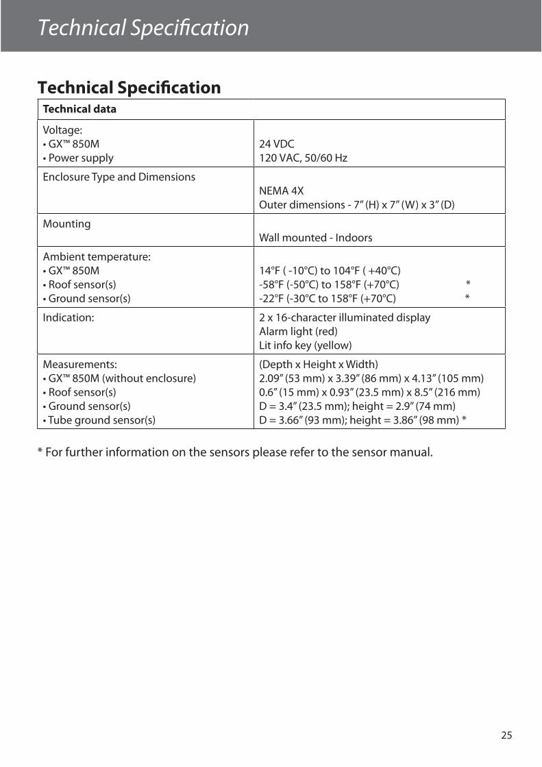
Technical Specifi cationTechnical data
Voltage:• GX™ 850M• Power supply
24 VDC120 VAC, 50/60 Hz
Enclosure Type and DimensionsNEMA 4XOuter dimensions - 7” (H) x 7” (W) x 3” (D)
MountingWall mounted - Indoors
Ambient temperature:• GX™ 850M• Roof sensor(s)• Ground sensor(s)
14°F ( -10°C) to 104°F ( +40°C) -58°F (-50°C) to 158°F (+70°C) *-22°F (-30°C to 158°F (+70°C) *
Indication: 2 x 16-character illuminated displayAlarm light (red)Lit info key (yellow)
Measurements:• GX™ 850M (without enclosure)• Roof sensor(s)• Ground sensor(s)• Tube ground sensor(s)
(Depth x Height x Width)2.09” (53 mm) x 3.39” (86 mm) x 4.13” (105 mm)0.6” (15 mm) x 0.93” (23.5 mm) x 8.5” (216 mm)D = 3.4” (23.5 mm); height = 2.9” (74 mm)D = 3.66” (93 mm); height = 3.86” (98 mm) *
* For further information on the sensors please refer to the sensor manual.
Technical Specifi cation
26
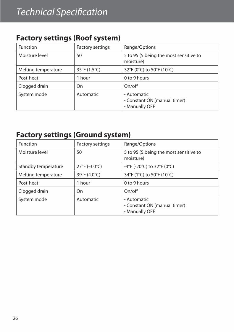
Factory settings (Roof system)Function Factory settings Range/Options
Moisture level 50 5 to 95 (5 being the most sensitive to moisture)
Melting temperature 35°F (1.5°C) 32°F (0°C) to 50°F (10°C)
Post-heat 1 hour 0 to 9 hours
Clogged drain On On/off
System mode Automatic • Automatic• Constant ON (manual timer)• Manually OFF
Factory settings (Ground system)Function Factory settings Range/Options
Moisture level 50 5 to 95 (5 being the most sensitive to moisture)
Standby temperature 27°F (-3.0°C) -4°F (-20°C) to 32°F (0°C)
Melting temperature 39°F (4.0°C) 34°F (1°C) to 50°F (10°C)
Post-heat 1 hour 0 to 9 hours
Clogged drain On On/off
System mode Automatic • Automatic• Constant ON (manual timer)• Manually OFF
Technical Specifi cation
Appendix
27
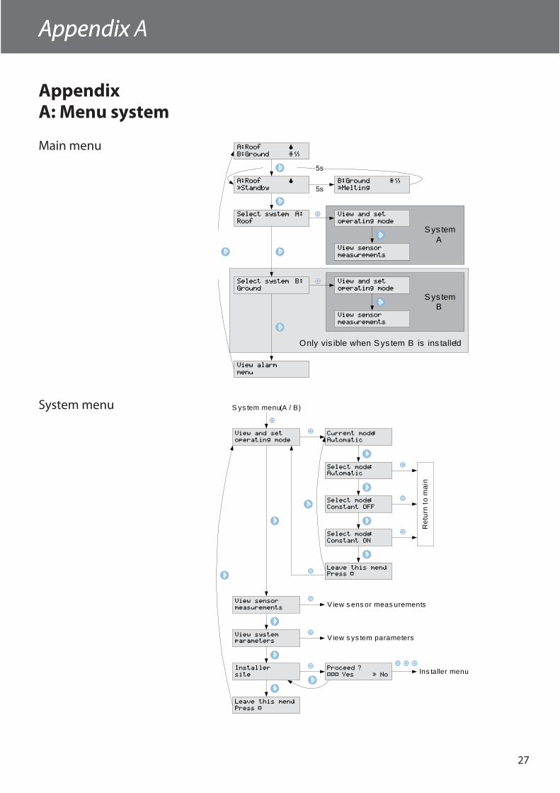
AppendixA: Menu system
Main menu
Sys tem B
Sys tem A
A:Roof ˜
ÚStandby
B:Ground ¯ˆı
ÚMelting
Select system A:
Roof
Select system B:
Ground
View alarm
menu
5s
A:Roof ˜
B:Ground ¯ˆı
5s
View and set
operating mode
View sensor
measurements
View and set
operating mode
View sensor
measurements
Only vis ible when Sys tem B is ins talled!
System menu
View and set
operating mode
View sensor
measurements
View systemparameters
Current mode:
Automatic
Select mode:Automatic
Select mode:
Constant OFF
Select mode:
Constant ON
Leave this menu:Press Û
Installer
site
Proceed ?
ÛÛÛ Yes Ω NoIns taller menu
Leave this menu:
Press Û
View s ens or meas urements
V iew s ys tem parameters
S ys tem menu (A / B)
Ret
urn
to m
ain
Appendix A
28
Appendix
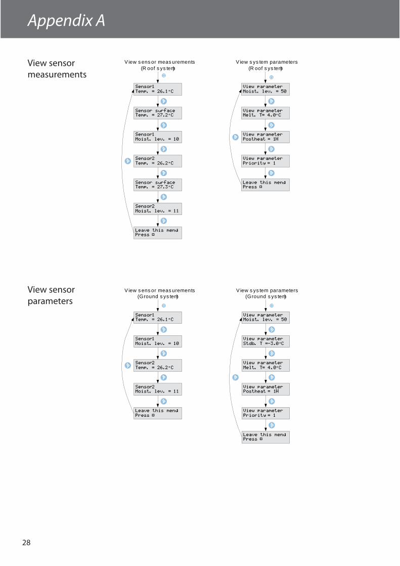
View sensormeasurements
Sensor1
Temp. = 26.1≥C
Sensor1
Moist. lev. = 10
Sensor2
Temp. = 26.2≥C
Sensor2
Moist. lev. = 11
Leave this menu:Press Û
View s ens or meas urements(R oof s ys tem)
Sensor surfaceTemp. = 27.2≥C
Sensor surfaceTemp. = 27.3≥C
View parameter
Moist. lev. = 50
View parameterMelt. T= 4.0≥C
View parameter
Postheat = 1H
View parameter
Priority = 1
View s ys tem parameters(R oof s ys tem)
Leave this menu:Press Û
Sensor1Temp. = 26.1≥C
Sensor1
Moist. lev. = 10
Sensor2
Temp. = 26.2≥C
Sensor2Moist. lev. = 11
Leave this menu:
Press Û
View s ens or meas urements(Ground s ys tem)
View parameterMoist. lev. = 50
View parameter
Stdb. T =-3.0≥C
View parameter
Melt. T= 4.0≥C
View parameterPostheat = 1H
View parameter
Priority = 1
View s ys tem parameters(Ground s ys tem)
Leave this menu:Press Û
View sensorparameters
Appendix A
Appendix
29
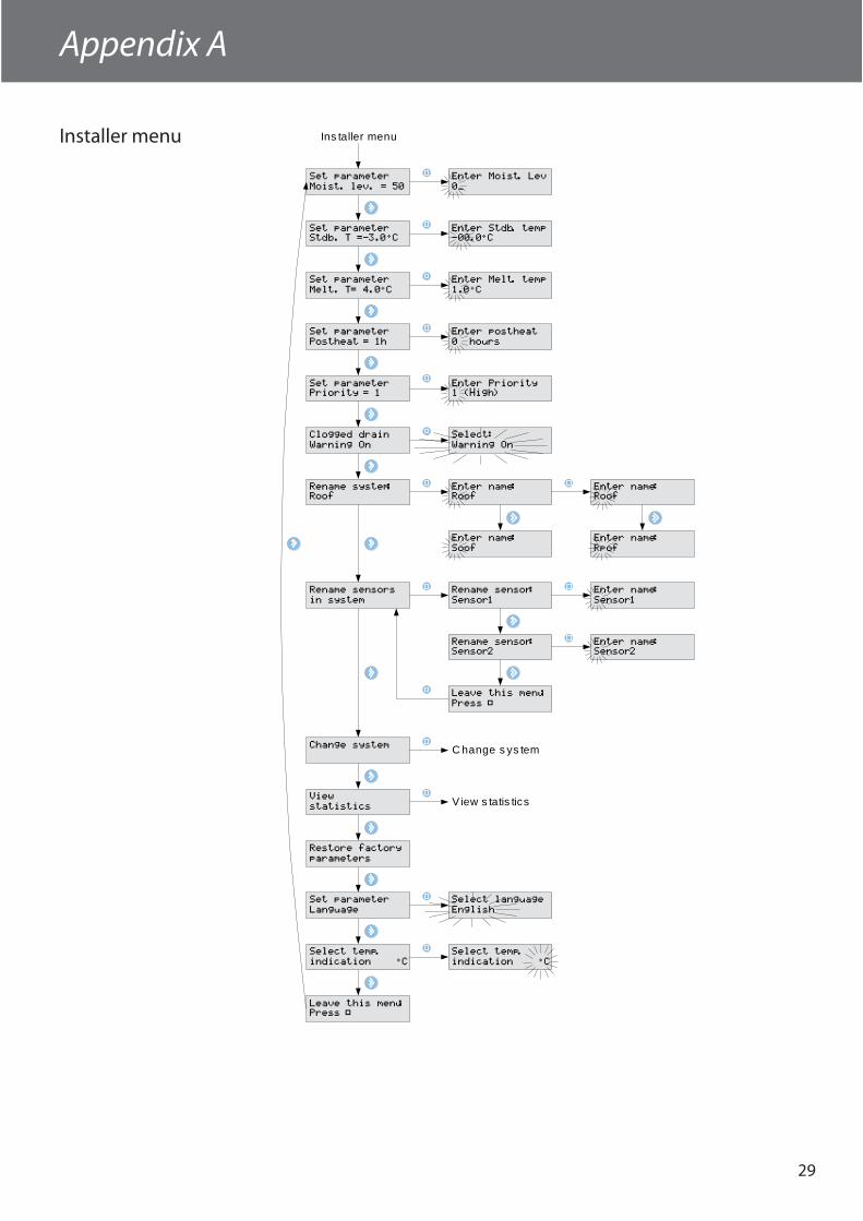
Installer menu
Set parameter
Moist. lev. = 50
Set parameterStdb. T =-3.0≥C
Set parameter
Melt. T= 4.0≥C
Set parameter
Postheat = 1h
Clogged drain
Warning On
View
statistics
Leave this menu:Press Û
Enter Moist. Lev
0_
Enter Stdb. temp-00.0≥C
Enter Melt. temp
1.0≥C
Enter postheat
0 hours
Select:
Warning On
Rename system:Roof
Enter name:Roof
Enter name:Roof
Enter name:
Soof
Enter name:
Rpof
Set parameterPriority = 1
Enter Priority1 (High)
Rename sensors
in system
Rename sensor:
Sensor1
Enter name:
Sensor1
Rename sensor:Sensor2
Leave this menu:
Press Û
View s tatis tics
Ins taller menu
Enter name:Sensor2
Restore factory
parameters
Change system C hange s ys tem
Select temp.
indication ÙC
Select temp.
indication ÙC
Set parameter
Language
Select language
English
Appendix A
30
Appendix
Change system
Appendix A
C hange s ys tem
Checking system
<------>
No groundsensors found!
Only if any pas s ive (dis abled) s ens ors are working again!
1 sensor(s)reactivated!
Replace sensor:Sensor1 03FB2F
Add sensor:ID: 03ABC1
Add sensor:
ID: 03DEF1
Cancel addsensor?
Replace sensor:
Sensor2 03FC24
Cancel replacesensor?
Sensor added!
Sensor replaced!
Add sensor:
ID: 03ABC1
Add sensor:
ID: 03DEF1
Cancel replacesensor?
If no new s ens ors are found (E xample s howing ground
s ys tem).
If new s ens or(s) found, but no pas s ive s ens or(s) found.
If new s ens or(s) found and pas s ive s ens or(s) found.
Appendix
31
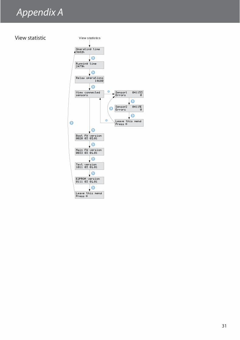
View statistic
View connectedsensors
Sensor1 041153Errors 0
Sensor2 04115C
Errors 0
View s tatis tics
Operating time
3682h
Running time2479h
Relay operations
14680
Boot FW version0020 03 03.01
Main FW version
0033 03 01.01
Text version1011 03 01.01
E2PROM version
0111 03 01.01
Leave this menu:
Press Û
Leave this menu:
Press Û
Appendix A
32
User ManualAppendix B
Standby(No heating)
Melting(Heating)
Post-heating(Heating)
Measuringtemperature(No heating)
Temperature < Melting temperatureandMoisture > Moisture limit
Moisture < Moisture limit
After 3 hours
0-20 minutes
Post-heating time elapsed
Temperature >Melting temperature
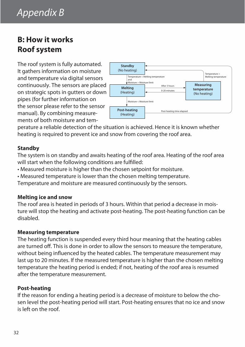
B: How it worksRoof system
The roof system is fully automated. It gathers information on moisture and temperature via digital sensors continuously. The sensors are placed on strategic spots in gutters or down pipes (for further information on the sensor please refer to the sensor manual). By combining measure-ments of both moisture and tem-perature a reliable detection of the situation is achieved. Hence it is known whether heating is required to prevent ice and snow from covering the roof area.
StandbyThe system is on standby and awaits heating of the roof area. Heating of the roof area will start when the following conditions are fulfi lled:• Measured moisture is higher than the chosen setpoint for moisture.• Measured temperature is lower than the chosen melting temperature.Temperature and moisture are measured continuously by the sensors.
Melting ice and snowThe roof area is heated in periods of 3 hours. Within that period a decrease in mois-ture will stop the heating and activate post-heating. The post-heating function can be disabled.
Measuring temperatureThe heating function is suspended every third hour meaning that the heating cables are turned off . This is done in order to allow the sensors to measure the temperature, without being infl uenced by the heated cables. The temperature measurement may last up to 20 minutes. If the measured temperature is higher than the chosen melting temperature the heating period is ended; if not, heating of the roof area is resumed after the temperature measurement.
Post-heatingIf the reason for ending a heating period is a decrease of moisture to below the cho-sen level the post-heating period will start. Post-heating ensures that no ice and snow is left on the roof.
User Manual
33
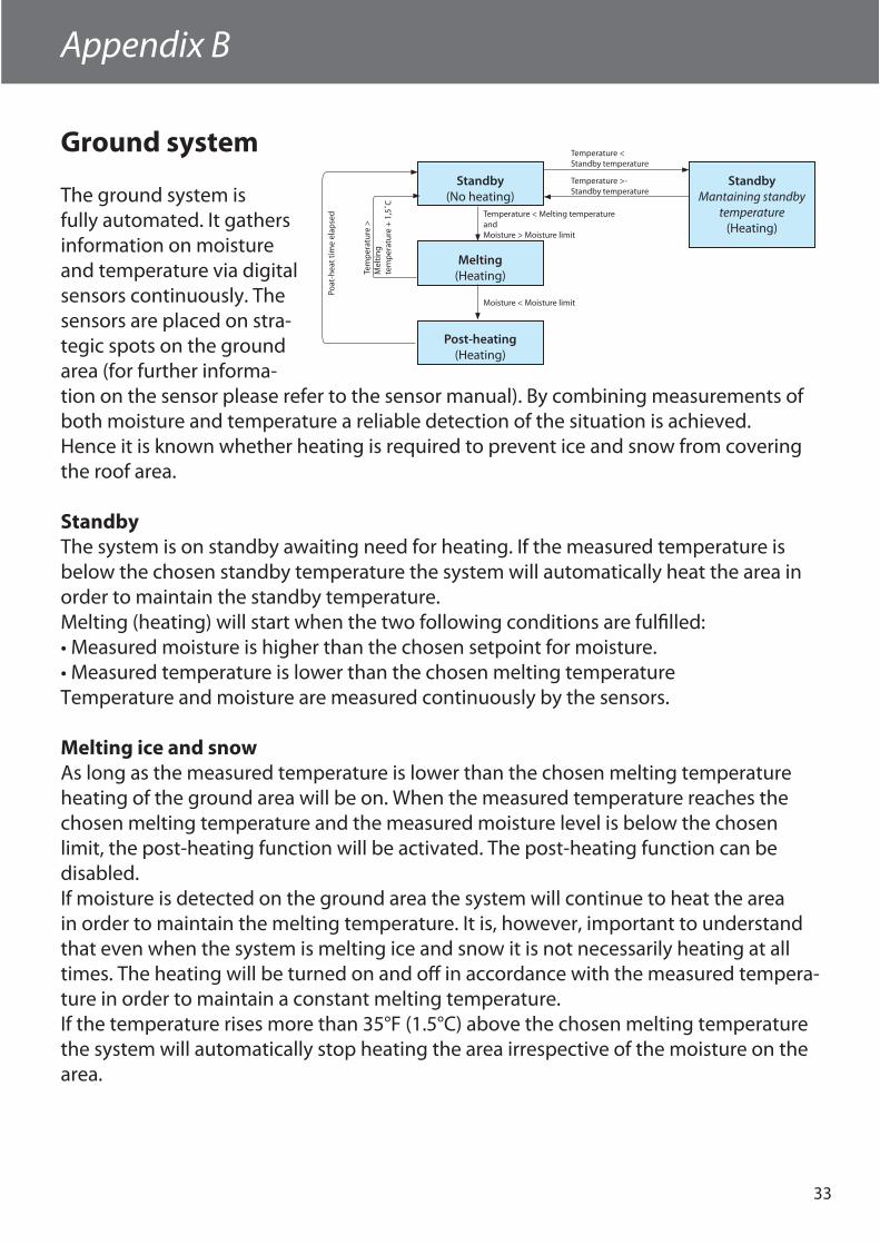
Ground system
The ground system is fully automated. It gathers information on moisture and temperature via digital sensors continuously. The sensors are placed on stra-tegic spots on the ground area (for further informa-tion on the sensor please refer to the sensor manual). By combining measurements of both moisture and temperature a reliable detection of the situation is achieved. Hence it is known whether heating is required to prevent ice and snow from covering the roof area.
StandbyThe system is on standby awaiting need for heating. If the measured temperature is below the chosen standby temperature the system will automatically heat the area in order to maintain the standby temperature.Melting (heating) will start when the two following conditions are fulfi lled:• Measured moisture is higher than the chosen setpoint for moisture.• Measured temperature is lower than the chosen melting temperatureTemperature and moisture are measured continuously by the sensors.
Melting ice and snowAs long as the measured temperature is lower than the chosen melting temperature heating of the ground area will be on. When the measured temperature reaches the chosen melting temperature and the measured moisture level is below the chosen limit, the post-heating function will be activated. The post-heating function can be disabled.If moisture is detected on the ground area the system will continue to heat the area in order to maintain the melting temperature. It is, however, important to understand that even when the system is melting ice and snow it is not necessarily heating at all times. The heating will be turned on and off in accordance with the measured tempera-ture in order to maintain a constant melting temperature.If the temperature rises more than 35°F (1.5°C) above the chosen melting temperature the system will automatically stop heating the area irrespective of the moisture on the area.
Appendix B
Standby(No heating)
Melting(Heating)
Post-heating(Heating)
StandbyMantaining standby
temperature(Heating)
Temperature < Melting temperatureandMoisture > Moisture limit
Moisture < Moisture limit
Temperature < Standby temperature
Temperature >- Standby temperature
Poat
-hea
t tim
e el
apse
d
Tem
per
atur
e >
Mel
ting
tem
per
atur
e +
1,5
˚C
34
User Manual
Post-heatingIf the reason for ending a heating period is a decrease of moisture to below the chosen level, the post-heating period will start. Post-heating ensures that no ice and snow is left on the ground.
If system priority is low, heating might be paused at any time!
The ground system uses heated sensors which under normal circumstances will hold a temperature of 35°F (1.5°C). In connection with measuring the area tempera-ture heating of the sensor is turned off for 90 minutes at a time. This is done in order to obtain a correct measurement of area temperature which is not infl uenced by sensor temperature. If a system only has one sensor this sensor is constantly heated for 90 minutes and then turned off for 90 minutes. This entails that measurement of tem-perature can be up to 3 hours delayed. With more than one sensor this performance is signifi cantly improved.
Security and energy consumptionHigh security – higher energy consumptionIf a high degree of security against ice and snow is wanted, make the following adjust-ments of the operation parameters:• Increase the standby temperature• Increase the melting temperature• Decrease the moisture level (close to setting 5)• Prolong the post-heat periodThis will give a high degree of security in even dry areas.
Low security – lower energy consumptionConversely, low energy consumption and a moderate level of security against ice and snow could be prioritized. In this case make the following adjustments of the operation parameters:• Decrease the standby temperature• Decrease the melting temperature• Increase the moisture level• Shorten the post-heat periodThis will give relatively low energy consumption, but the area may remain wet and icy in short periods.
The factory settings are average values providing a relatively high degree of security and moderate energy consumption.
Appendix B
User Manual
35
Appendix C
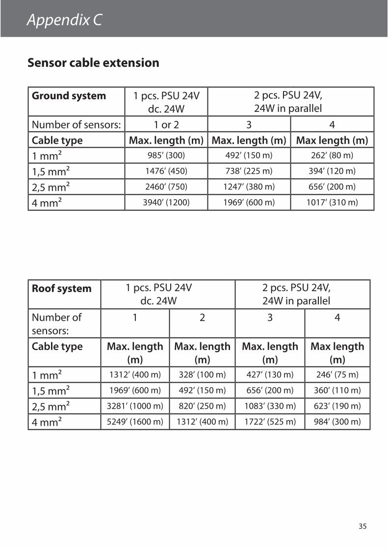
Sensor cable extension
Ground system 1 pcs. PSU 24V dc. 24W
Number of sensors: 1 or 2 3 4
Cable type Max. length (m) Max. length (m) Max length (m)1 mm² 985’ (300) 492’ (150 m) 262’ (80 m)
1,5 mm² 1476’ (450) 738’ (225 m) 394’ (120 m)
2,5 mm² 2460’ (750) 1247’ (380 m) 656’ (200 m)
4 mm² 3940’ (1200) 1969’ (600 m) 1017’ (310 m)
2 pcs. PSU 24V, 24W in parallel
Roof system
Number of sensors:
1 2 3 4
Cable type Max. length (m)
Max. length (m)
Max. length (m)
Max length (m)
1 mm² 1312’ (400 m) 328’ (100 m) 427’ (130 m) 246’ (75 m)
1,5 mm² 1969’ (600 m) 492’ (150 m) 656’ (200 m) 360’ (110 m)
2,5 mm² 3281’ (1000 m) 820’ (250 m) 1083’ (330 m) 623’ (190 m)
4 mm² 5249’ (1600 m) 1312’ (400 m) 1722’ (525 m) 984’ (300 m)
2 pcs. PSU 24V, 24W in parallel
1 pcs. PSU 24V dc. 24W
36
The Danfoss Warranty
1. INCOTERMS
The international rules for the interpretation of trade terms “Incoterms” shall apply to the commercial terms used herein.
2. CONFIRMATION OF ORDER
Danfoss shall not be deemed to have accepted an order until written confi rmation of the order from Danfoss is dispatched to the prospective purchaser. Quotations, pro forma invoices and the like, shall be subject to confi rmation by Danfoss.
3. TERMS OF DELIVERY
At Danfoss’ option, the goods can be delivered from any of the Danfoss factories, subsidiaries, or affi liated companies in or outside Canada. Failing special instructions, the goods will be dispatched in the way which Danfoss deems best without guaranteeing this to be the cheapest way of transport.
4. PRICE REGULATIONS
Danfoss reserves the right to adjust accepted prices in the event of alterations in rates of exchange, variations in costs of materials, changes in wages, interference on the part of the Government or similar conditions over which Danfoss has no control.
5. PACKING
Disposable packing is included in the price and will not be credited if returned. Reusable packing is not included in the price and shall be returned in accordance with Danfoss’ instructions at purchaser’s expense.
6. RISK
From the moment of delivery the purchaser shall bear all risks for the goods, and Danfoss shall not be responsible for loss and damage incurred during the transportation. If so desired by the purchaser, Danfoss will at the cost of and on behalf of the purchaser, eff ect marine Insurance in English all risk conditions from warehouse to warehouse, at the c.i.f. value of the goods plus 10% and, likewise, Danfoss will eff ect war risk insurance.
7. TERMS OF PAYMENT
Where payment is not received when due, an interest rate of 10% per annum over and above the actual total back charge will be payable. This rate of interest will also be used in cases where an extension of the period of credit has been granted. The purchaser shall not be allowed to retain payments, or to settle debts by setting off same against possible counterclaims, disputed by Danfoss, or to reduce the invoiced price.
8. TRANSFER OF OWNERSHIP
Until full payment for the goods has been received by Danfoss, the goods shall remain the property of Danfoss and shall not be pawned or pledged in any way.
9. TIME OF DELIVERY
Time of delivery is stated approximately. Danfoss shall not be liable for any delay due to causes beyond Danfoss’ control, including
The acceptance of the order confi rmation by the purchaser includes the acceptance of our “General Conditions of Sale and Warranty” as the only ruling condition. No modifi cation of these conditions will be recognized by Danfoss. Any express or implied condition, statement or warranty, statutory or otherwise - not stated herein is excluded.
GENERAL CONDITIONS FOR SALE AND WARRANTY
but not restricted to strikes, lockouts, labour disturbances or the like, or in consequence of extraordinary measures on the part of government, hindrances to transportation including ice or other transport diffi culties, delayed, incomplete or defective delivery of material ordered in due time from sub-suppliers, failing supply of electricity and similar obstacles to production, fi re or workshop accidents at own factories or at sub-suppliers.
10. INFORMATION
The information and technical data contained in catalogues, leafl ets and other written material constitutes an approximate guide only. No responsibility for errors or wrong interpretation can be placed on Danfoss. The purchaser cannot claim any rights based on this material. Such reservation shall also apply to suggestions, advice and other services rendered to customers, including installation and servicing instruction for the product delivered.
11. ALTERATIONS
Danfoss reserves the right to make alterations to their products without notice, also to products already placed on order.
12. WARRANTY
Provided that the terms of payment are observed, the purchaser is off ered a warranty of two (2) years on thermostats, PX, and RX Kits, ten (10) years on mats and cables. The period of warranty is running from the date stamped on the product. The warranty covers faulty manufacture, design and/or defective materials. The warranty shall cease to be valid if the product is repaired or altered without the consent of Danfoss, applied for purposes for which it is not designed or installed and applied contrary to the instructions given by Danfoss. Expenses in connection with dismantling and mounting shall not be paid by Danfoss. If defects occur while under warranty, the product shall be forwarded to Danfoss, insurance and freight paid. A description of the reason for returning the product shall be enclosed. Products returned shall be free of extraneous equipment. Products repaired under warranty will be returned to the purchaser, freight paid by Danfoss.Parts which have been replaced shall be the property of Danfoss. Any other liabilities are not accepted. Guarantee for products not of Danfoss’ own manufacture is only given to the same extent as given to Danfoss, however, not exceeding the normal Danfoss warranty.
13. SECONDARY DAMAGES
Danfoss shall not be held responsible for any indirect or consequential damage e.g. damages to person or property, consequential loss, including loss of production, loss of profi t, loss on goods in store or the like, which might arise out of defects and/or delay in delivery of the products sold, irrespective of the cause, including faulty manufacture, design of material.
14. NOTICE OF CLAIMS
Any claim or complaint as to defects and/or delay in delivery of the products shall be submitted in writing by the purchaser to Danfoss immediately.
37
The Danfoss Guarantee
The Danfoss Guarantee is granted to:
Name:
Phone:
Guarantee Certificate
Address:
Postal code:
Electrical Installation by:
Type of thermostat:
Installation date:
Production code:
Important!In order to obtain the Danfoss Guarantee, the following must be
carefully filled in. See other conditions on previous page.
Supplier information
Danfoss Heating North America6711 Mississauga Road, Suite 410Mississauga, Ontario, L5N 2W3Phone 866-676-8062Fax 905-285-2056

38
Notes

39
Notes
F̊/˚C
VICKM222M 07/2011


![Rh10032.™tuyz.k]rkzz 6giqgxj˙gyuj˙gy[vuyq_z[pk gqz[gro‘gioyulz]gx[zoyqÀxt_](https://img.pdfslide.net/doc/110x75/5b88bdc37f8b9abe1e8befd1/-tuyzkrkzz-6giqgxjgyujgyvuyqzpk-gqzgrogioyulzgxzoyqaxt-.jpg)