Embed Size (px)
Citation preview
Technical Information / Datasheet SK TU3-PBR-24V
PROFIBUS DP Bus module TI 275900160 V 1.0 4116 EN
Pos: 2 /Technische Infor mationen/SK xU x - Er weiter ung en/PR OFIBUS DP/SK TU 3-PBR-24V/275900160 Basisinfor mati onen @ 8\mod_1462371531489_388.docx @ 2251762 @ @ 1
SK TU3-PBR-24V Part number: 275 900 160
PROFIBUS® DP – External Bus Interface Pos: 9 /Technische Infor mationen/SK xU x - Er weiter ung en/Allgemein - Systemübergreifend/War nhi nweise_TI_s_Busschitts tell en_allgemei n [SK xU x-.. .] @ 13\mod_1475837761064_388.docx @ 2263751 @ @ 1
The bus interface may only be installed and commissioned by qualified electricians. An electrician is a person who, because of their technical training and experience, has sufficient knowledge with regard to
• Switching on, switching off, isolating, earthing and marking power circuits and devices, • Proper maintenance and use of protective devices in accordance with defined safety standards.
DANGER Danger of electric shock
The frequency inverter carries hazardous voltage for up to 5 minutes after being switched off. • Work must not be carried out unless the frequency inverter has been disconnected from the voltage and at
least 5 minutes has elapsed since the mains was switched off!
NOTICE Validity of document
This document is only valid in conjunction with the operating instructions of the respective frequency inverter and the bus communication manual for this bus interface ( See overview at end of document). These documents contain all of the information that is required for safe commissioning of the bus interface module and the frequency inverter.
Pos: 11 /Technische Informati onen/SK xU x - Er weiterungen/PROFIBU S D P/SK TU3- PBR- 24V/275900160 Basisinfor mationen_2 @ 13\mod_1475846169566_388.docx @ 2264976 @ 555 @ 1
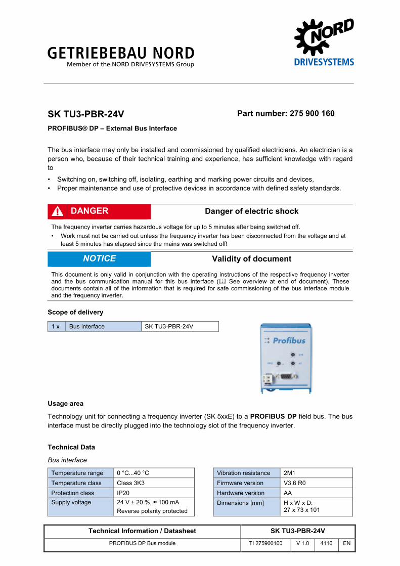
Scope of delivery
1 x Bus interface SK TU3-PBR-24V
Usage area
Technology unit for connecting a frequency inverter (SK 5xxE) to a PROFIBUS DP field bus. The bus interface must be directly plugged into the technology slot of the frequency inverter.
Technical Data
Bus interface
Temperature range 0 °C...40 °C Vibration resistance 2M1 Temperature class Class 3K3 Firmware version V3.6 R0 Protection class IP20 Hardware version AA Supply voltage 24 V ± 20 %, ≈ 100 mA
Reverse polarity protected Dimensions [mm] H x W x D:
27 x 73 x 101
PROFIBUS DP Bus module – SK TU3-PBR-24V
2 / 7 TI 275900160 - 4116
Bus specification
PROFIBUS DP Max. 12 MBit/s electrical isolation 500 Veff Bus connection SUB-D9-PROFIBUS connector Status display 2 LEDs Topology Linear bus Power setting PROFIBUS DP-V0 Cable Cable type A according to EN 50170 (drilled, shielded two conductor cable) Cable length depending on transmission speed:
Bus cable length Transfer rate 400 m 500 KBit/s
200 m 1500 KBit/s
100 m 3…12 MBit/s
Shield via SUB-D9-PROFIBUS connector* PE connection Shielding terminal at bus interface, cable cross-section 1.5 mm2 (flat connecting sleeve
included in scope of delivery)
* Connect shield in SUB-D9-PROFIBUS connector to metal housing of SUB-D9-PROFIBUS connector and the functional earth over a large area.
Power
Update interval for process data between bus interface and frequency inverter ≤ 1.25 ms Parameter read access on the frequency inverter ≈ 12 ms Parameter write access with storage in EEPROM ≈ 25 ms
Pos: 18 /Technische Informati onen/SK xU x - Er weiterungen/PROFIBU S D P/M er kmal e [PR B Allgemein] @ 8\mod_1462366023559_388.docx @ 2251321 @ 5 @ 1
Bus interface characteristics
Communication Performance levels DP-V0
Cyclic useful data connection between DP master and DP slaves (point-to-point useful data communication or Multicast)
Communication Performance levels DP-V1
Acyclic data communication between DP master DPM1 and DP slaves
Transfer Method RS485 Addressing SK TU3-PBR SK TU3-PBR-24V SK xU4-PBR
Parameter P508 at frequency inverter
Rotary coding switch or parameter P508 at frequency inverter
DIP switch or parameter P160
Synchronisation Sync mode (synchronisation of outputs) and Freeze mode (synchronisation of inputs)
Bus access • Token Passing procedure • Master/Slave procedure • Mono-Master or Multi-Master System
Access for NORD diagnosis tool via diagnostics socket on the device (if available) and via frequency inverter
Pos: 19 /Technische Informati onen/SK xU x - Er weiterungen/Allgemei n - Sys temübergreifend/M ontag e [SK TU3- xxx] @ 8\mod_1461592936875_388.docx @ 2249319 @ 5 @ 1
PROFIBUS DP Bus module – SK TU3-PBR-24V
TI 275900160 - 4116 3 / 7
Installation
Information Installing the SK TU3-... bus interface
Installation of a technology unit separate from the frequency inverter is not possible, since it must be connected directly to the frequency inverter.
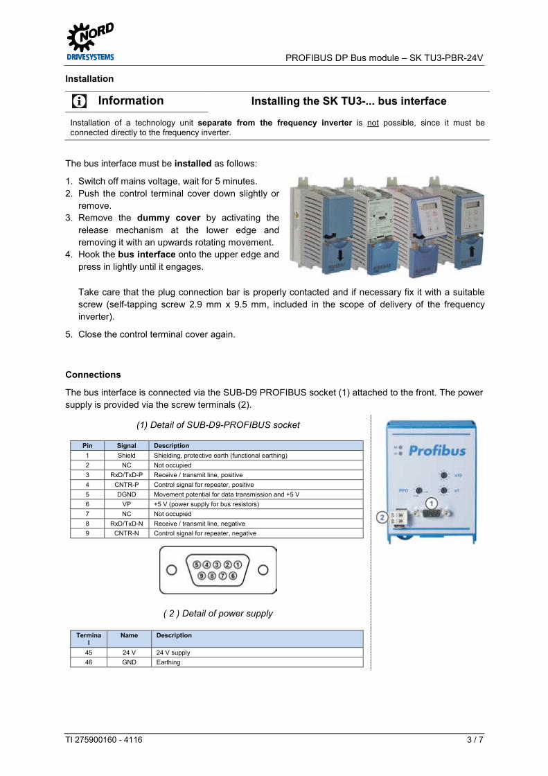
The bus interface must be installed as follows:
1. Switch off mains voltage, wait for 5 minutes. 2. Push the control terminal cover down slightly or
remove. 3. Remove the dummy cover by activating the
release mechanism at the lower edge and removing it with an upwards rotating movement.
4. Hook the bus interface onto the upper edge and press in lightly until it engages.
Take care that the plug connection bar is properly contacted and if necessary fix it with a suitable screw (self-tapping screw 2.9 mm x 9.5 mm, included in the scope of delivery of the frequency inverter).
5. Close the control terminal cover again.
Pos: 23 /Technische Informati onen/SK xU x - Er weiterungen/PROFIBU S D P/Anschl üsse [SK TU 3-PBR- 24V] @ 8\mod_1462801030119_388.docx @ 2251798 @ 5 @ 1
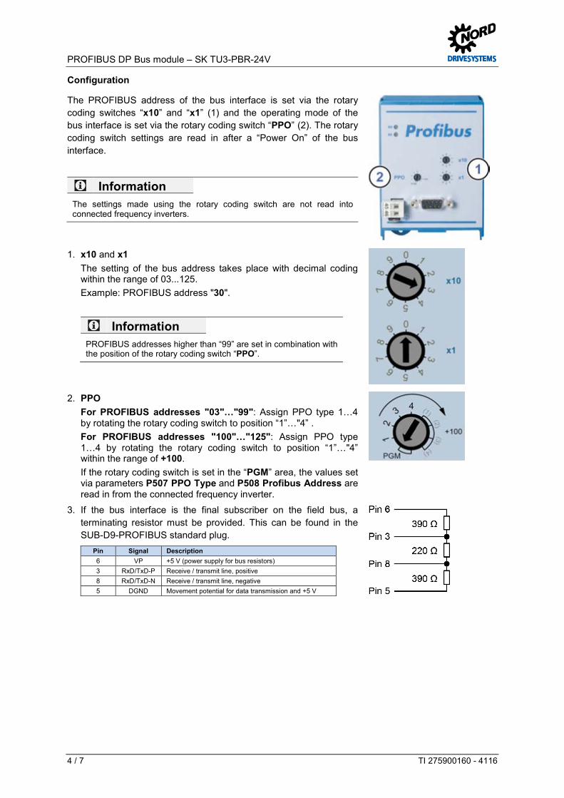
Connections
The bus interface is connected via the SUB-D9 PROFIBUS socket (1) attached to the front. The power supply is provided via the screw terminals (2).
(1) Detail of SUB-D9-PROFIBUS socket
Pin Signal Description 1 Shield Shielding, protective earth (functional earthing) 2 NC Not occupied 3 RxD/TxD-P Receive / transmit line, positive 4 CNTR-P Control signal for repeater, positive 5 DGND Movement potential for data transmission and +5 V 6 VP +5 V (power supply for bus resistors) 7 NC Not occupied 8 RxD/TxD-N Receive / transmit line, negative 9 CNTR-N Control signal for repeater, negative
( 2 ) Detail of power supply
Terminal
Name Description
45 24 V 24 V supply 46 GND Earthing
Pos: 28 /Technische Informati onen/SK xU x - Er weiterungen/PROFIBU S D P/Konfigur ati on [SK TU 3-PBR-24V] @ 8\mod_1462366018738_388.docx @ 2251033 @ 5 @ 1
PROFIBUS DP Bus module – SK TU3-PBR-24V
4 / 7 TI 275900160 - 4116
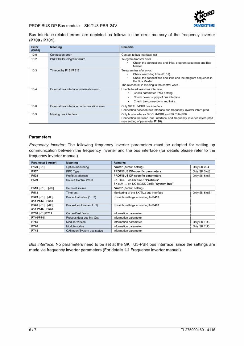
Configuration
The PROFIBUS address of the bus interface is set via the rotary coding switches “x10” and “x1” (1) and the operating mode of the bus interface is set via the rotary coding switch “PPO” (2). The rotary coding switch settings are read in after a “Power On” of the bus interface.
Information The settings made using the rotary coding switch are not read into connected frequency inverters.
1. x10 and x1 The setting of the bus address takes place with decimal coding within the range of 03...125. Example: PROFIBUS address "30".
Information PROFIBUS addresses higher than “99” are set in combination with the position of the rotary coding switch “PPO”.
2. PPO For PROFIBUS addresses "03"…"99": Assign PPO type 1…4
by rotating the rotary coding switch to position “1”…"4” . For PROFIBUS addresses "100"…"125": Assign PPO type
1…4 by rotating the rotary coding switch to position “1”…"4” within the range of +100.
If the rotary coding switch is set in the “PGM” area, the values set via parameters P507 PPO Type and P508 Profibus Address are read in from the connected frequency inverter.
3. If the bus interface is the final subscriber on the field bus, a terminating resistor must be provided. This can be found in the SUB-D9-PROFIBUS standard plug.
Pin Signal Description 6 VP +5 V (power supply for bus resistors) 3 RxD/TxD-P Receive / transmit line, positive 8 RxD/TxD-N Receive / transmit line, negative 5 DGND Movement potential for data transmission and +5 V
Pos: 31 /Technische Informati onen/SK xU x - Er weiterungen/PROFIBU S D P/LED Anzeigen [SK TU3- PBR] @ 8\mod_1462366022436_388.docx @ 2251257 @ 5 @ 1

PROFIBUS DP Bus module – SK TU3-PBR-24V
TI 275900160 - 4116 5 / 7
LED indicators
The operating statuses of the bus interface are visualised using LED indicators. No. Name Colour Meaning
1 BR green PROFIBUS DP Status
BE red PROFIBUS DP Error
Pos: 34 /Technische Informati onen/SK xU x - Er weiterungen/PROFIBU S D P/LED Anzeigen - PR OFIBUS-spezifische LED [nur SK TU3-PBR] @ 8\mod_1462366019808_388.docx @ 2251097 @ @ 1
PROFIBUS DP-specific LED BR
(Bus Ready, PROFIBUS DP
Status)
BE (Bus Error,
PROFIBUS DP Error)
Meaning
OFF OFF Bus interface not ready or no power supply. Steady
illumination in green
OFF Normal operation, cyclic data exchange via PROFIBUS DP.
Steady illumination in
green
Steady illumination in
red
Defective operation (e.g. PPO type changed during operation).
Flashing green (1 s)
OFF No process data received after switching on (e.g. no connection to PROFIBUS DP master).
Flashing green (1 s)
Brief illumination
Bus interface initialisation (after switching on the bus interface or changing a PROFIBUS-specific parameter at the connected frequency inverter).
Flashing green (1 s)
Steady illumination in
red
Timeout due to process data reception: The watchdog timer parameterized by the PROFIBUS DP master has elapsed without reception of new process data for a maximum of 3 seconds (e.g. baud rate not detected or cable break).
Flashing green (1 s)
Flashing red (1 s)
Timeout due to process data reception: The time set in parameter P513 “Telegram failure time” has elapsed without new process data being received.
Flashing green (1 s)
Flashing red (0.5 s)
Communication between frequency inverter and PROFIBUS DP interface interrupted.
Pos: 39 /Technische Informati onen/SK xU x - Er weiterungen/PROFIBU S D P/Fehler mel dungen PROFIBU S D P-Busschnitts tell en [SK xU x- PBR - Allgemein] @ 8\mod_1462366017614_388.docx @ 2250969 @ 5 @ 1
Error messages
Error messages from the bus interface – current or archived messages relating to the last fault - can be read out via module parameter P170 (SK xU4-PBR only). The error messages are lost if the bus interface is switched off.
Error Meaning Remarks 100.0 EEPROM error EMC faults, bus interface defective 101.0 System bus 24 V missing No 24 V voltage on bus, connections not correct 102.0 Bus timeout P151 By means of timeout supervision parameter P151/P513 103.0 System bus BUS OFF No 24 V supply to the bus, connections not correct 500.0 PROFIBUS ASIC error No communication with ASIC 501.0 PROFIBUS address incorrect Address outside permissible range (3…125) 502.0 PROFIBUS Timeout Telegram transfer error
PROFIBUS DP Bus module – SK TU3-PBR-24V
6 / 7 TI 275900160 - 4116
Bus interface-related errors are depicted as follows in the error memory of the frequency inverter (P700 / P701).
Error (E010)
Meaning Remarks
10.0 Connection error Contact to bus interface lost 10.2 PROFIBUS telegram failure Telegram transfer error
• Check the connections and links, program sequence and Bus Master.
10.3 Timeout by P151/P513 Telegram transfer error. • Check watchdog time (P151). • Check the connections and links and the program sequence in
the Bus Master. The release bit is missing in the control word.
10.4 External bus interface initialisation error Unable to address bus interface. • Check parameter P746 setting. • Check power supply of bus interface. • Check the connections and links.
10.8 External bus interface communication error Only SK TU3-PBR bus interface: Connection between bus interface and frequency inverter interrupted.
10.9 Missing bus interface Only bus interfaces SK CU4-PBR and SK TU4-PBR: Connection between bus interface and frequency inverter interrupted (see setting of parameter P120).
Pos: 40 /Technische Informati onen/SK xU x - Er weiterungen/PROFIBU S D P/Par ameter [Frequenzumrichter SK 5xxE - PROFIBU S D P] @ 8\mod_1462888940213_388.docx @ 2251900 @ 5 @ 1
Parameters
Frequency inverter: The following frequency inverter parameters must be adapted for setting up communication between the frequency inverter and the bus interface (for details please refer to the frequency inverter manual).
Parameter [-Array] Meaning Remarks P120 [-01] Option monitoring "Auto" (default setting) Only SK xU4 P507 PPO Type PROFIBUS DP-specific parameters Only SK 5xxE P508 Profibus address PROFIBUS DP-specific parameters Only SK 5xxE P509 Source Control Word SK TU3-… on SK 5xxE: "Profibus"
SK xU4-… on SK 180/SK 2xxE: "System bus"
P510 [-01 ]…[-02] Setpoint source "Auto" (default setting) P513 Time-out Monitoring of the SK TU3 bus interface Only SK 5xxE P543 [-01]…[-03] and P543…P545
Bus actual value (1…3) Possible settings according to P418
P546 [-01]…[-03] and P546…P548
Bus setpoint value (1...3) Possible settings according to P400
P700 [-01]/P701 Current/last faults Information parameter P740/P741 Process data bus In / Out Information parameter P745 Module version Information parameter Only SK TU3 P746 Module status Information parameter Only SK TU3 P748 CANopen/System bus status Information parameter
Pos: 42 /Technische Informati onen/SK xU x - Er weiterungen/PROFIBU S D P/Par ameter [SK TU 3-PBR] @ 8\mod_1462366024085_388.docx @ 2251353 @ @ 1
Bus interface: No parameters need to be set at the SK TU3-PBR bus interface, since the settings are made via frequency inverter parameters (For details Frequency inverter manual). Pos: 44 /Technische Informati onen/SK xU x - Er weiterungen/Allgemei n - Sys temübergreifend/Par ameterzugriff und Di agnose [Bus BG - Allgemei n] @ 3\mod_1363794074590_388.docx @ 61915 @ 5 @ 1
PROFIBUS DP Bus module – SK TU3-PBR-24V
TI 275900160 - 4116 7 / 7
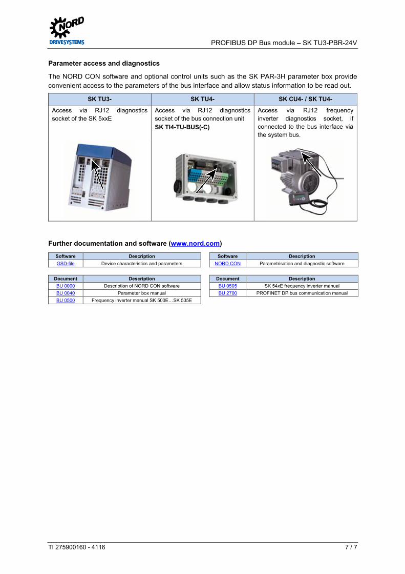
Parameter access and diagnostics
The NORD CON software and optional control units such as the SK PAR-3H parameter box provide convenient access to the parameters of the bus interface and allow status information to be read out.
SK TU3- SK TU4- SK CU4- / SK TU4-
Access via RJ12 diagnostics socket of the SK 5xxE
Access via RJ12 diagnostics socket of the bus connection unit SK TI4-TU-BUS(-C)
Access via RJ12 frequency inverter diagnostics socket, if connected to the bus interface via the system bus.
Pos: 45 /Technische Informati onen/SK xU x - Er weiterungen/PROFIBU S D P/Weiter führende D okumentati onen und Software [SK TU 3-PBR] @ 8\mod_1462366028909_388.docx @ 2251641 @ 5 @ 1
Further documentation and software (www.nord.com)
Software Description Software Description GSD-file Device characteristics and parameters NORD CON Parametrisation and diagnostic software
Document Description Document Description BU 0000 Description of NORD CON software BU 0505 SK 54xE frequency inverter manual BU 0040 Parameter box manual BU 2700 PROFINET DP bus communication manual BU 0500 Frequency inverter manual SK 500E…SK 535E
=== Ende der Liste für Textmar ke Inhalt ===