Embed Size (px)
Citation preview
HART® Field Device SpecificationP ar t N u m be r : 3 - 9 00 0- 7 6 2 , r e v . 3
R e l e a se : Release: 31 January 2014
DanielTM 3810 Series Liquid Ultrasonic Meters
HART is a registered Trademark of the HART Communication Foundation
3814 Liquid Ultrasonic Flow Meter 3812 Liquid Ultrasonic Flow Meter
3818 LNG Liquid Ultrasonic Flow Meter

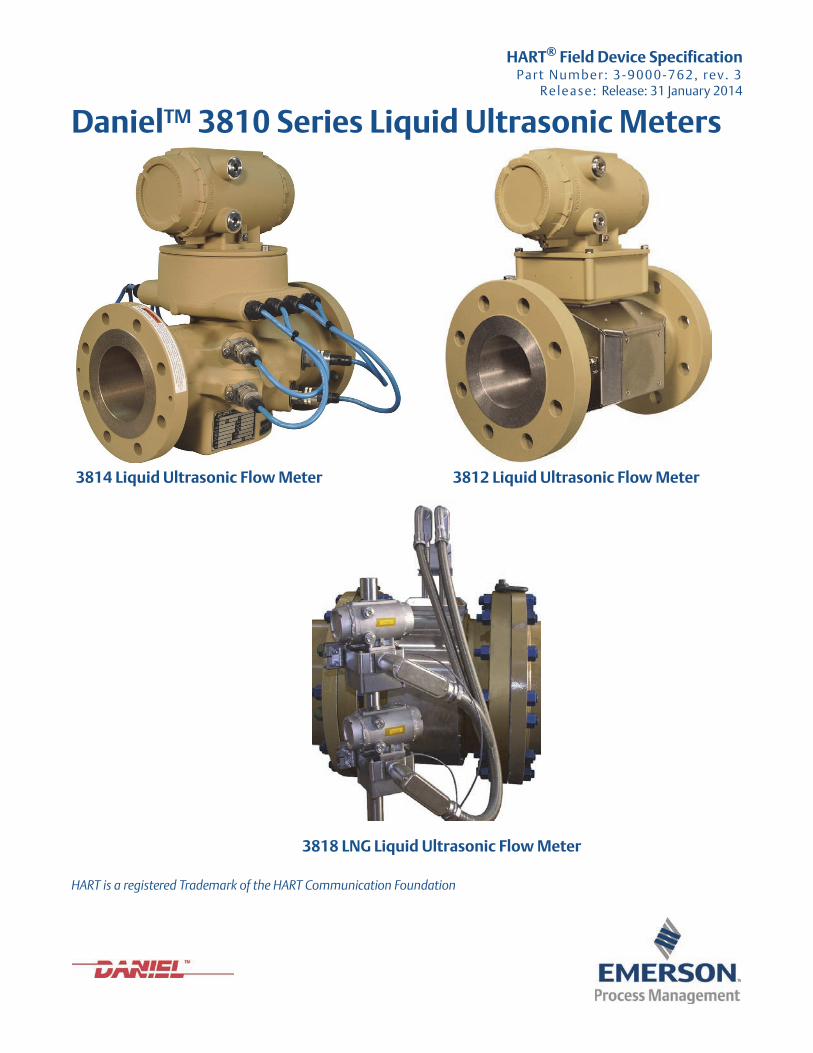
Daniel customer service
• Customer Service: [email protected]
• Customer Support: [email protected]
• Asia-Pacific: [email protected]
• Europe: [email protected]
Location Telephone number Fax number
North America/Latin America +1.713.467.6000 +1.713.827.4805
Daniel Customer Service +1.713.827.6413 +1.713.827.6312
USA (toll free) +1.888.356.9001 +1.713.827.3380
Asia Pacific (Republic of Singapore) +65.6777.8211 +65.6777.0947.0743
Europe (Stirling Scotland, UK) +44 (0)1786.433400 +44 (0)1786.433401
Middle East Africa (Dubai, UAE) +971 4 8118100 +971 4 8865465
Return Material Authorization (RMA)
A Return Material Authorization (RMA) number must be obtained prior to returning any equipment for any reason. Download the RMA form from the Support Services web page by selecting the link below.
www2.emersonprocess.com/EN-US/BRANDS/DANIEL/SUPPORT-SERVICES/Pages/Support-Services.aspx?
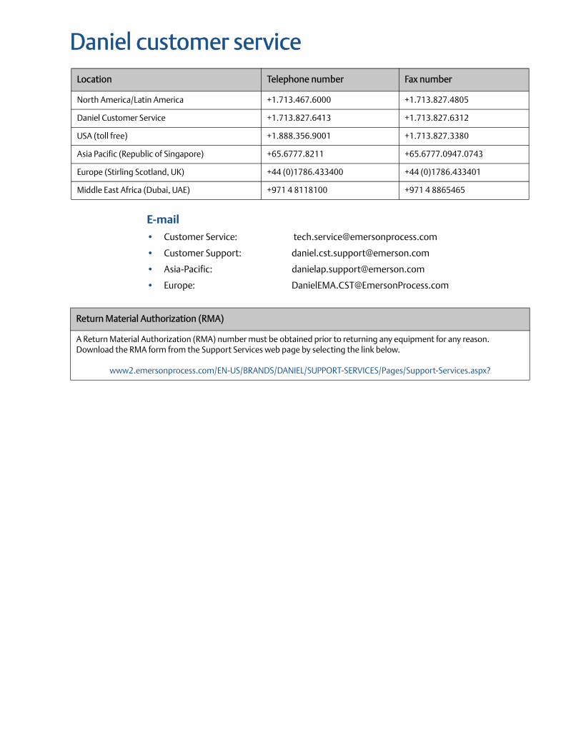
Signal words and symbolsPay special attention to the following signal words, safety alert symbols and statements:
ImportantImportant is a statement the user needs to know and consider.
TipTip provides information or suggestions for improved efficiency or best results.
NoteNote is a “general by-the-way” content not essential to the main flow of information.
This is a safety alert symbol. It is used to alert you to potential physical injury hazards. Obey all safety messages that follow this symbol to avoid possible injury or death.
Safety alert symbol
Danger indicates a hazardous situation which, if not avoided, will result in death or serious injury.
Warning indicates a hazardous situation which, if not avoided, could result in death or serious injury.
Caution indicates a hazardous situation which, if not avoided, could result in minor or moderate injury.
Notice is used to address safety messages or practices not related to personal injury.
Important safety instructionsDaniel Measurement and Control, Inc. (Daniel) designs, manufactures and tests products tofunction within specific conditions. Because these products are sophisticated technicalinstruments, it is important that the owner and operation personnel strictly adhere both to theinformation printed on the product and to all instructions provided in this manual prior toinstallation, operation, and maintenance.
Daniel also urges you to integrate this manual into your training and safety program.
BE SURE ALL PERSONNEL READ AND FOLLOW THE INSTRUCTIONS IN THIS MANUAL AND ALLNOTICES AND PRODUCT WARNINGS.
Product owners (Purchasers):
• Use the correct product for the environment and pressures present. See technical data or product specifications for limitations. If you are unsure, discuss your needs with your Daniel representative.
• Inform and train all personnel in the proper installation, operation, and maintenance of this product.
• To ensure safe and proper performance, only informed and trained personnel should install, operate, repair and maintain this product.
• Verify that this is the correct instruction manual for your Daniel product. If this is not the correct documentation, contact Daniel at 1-713-827-6314. You may also download the correct manual from:
http://www.daniel.com
• Save this instruction manual for future reference.
• If you resell or transfer this product, it is your responsibility to forward this instruction manual along with the product to the new owner or transferee.
• ALWAYS READ AND FOLLOW THE INSTALLATION, OPERATIONS, MAINTENANCE AND TROUBLESHOOTING MANUALS AND ALL PRODUCT WARNINGS AND INSTRUCTIONS.
• Do not use this equipment for any purpose other than its intended service. This may result in property damage and/or serious personal injury or death.
Installing, operating or maintaining a Daniel product improperly could lead to serious injury or death from explosion or exposure to dangerous substances. To reduce this risk:
• Comply with all information on the product, in this manual, and in any local and national codes that apply to the product.
• Do not allow untrained personnel to work with this product.
• Use Daniel parts and work procedures specified in this manual.
Product Operation Personnel:
• To prevent personal injury, personnel must follow all instructions of this manual prior to and during operation of the product.
• Follow all warnings, cautions, and notices marked on, and supplied with, this product.
• Verify that this is the correct instruction manual for your Daniel product. If this is not the correct documentation, contact Daniel at 1-713-827-6314. You may also download the correct manual from:
http://www.daniel.com
• Read and understand all instructions and operating procedures for this product.
• If you do not understand an instruction, or do not feel comfortable following the instructions, contact your Daniel representative for clarification or assistance.
• Install this product as specified in the INSTALLATION section of this manual per applicable local and national codes.
• Follow all instructions during the installation, operation, and maintenance of this product.
• Connect the product to the appropriate pressure and electrical sources when and where applicable.
• Ensure that all connections to pressure and electrical sources are secure prior to and during equipment operation.
• Use only replacement parts specified by Daniel. Unauthorized parts and procedures can affect this product's performance, safety, and invalidate the warranty. “Look-a-like” substitutions may result in deadly fire, explosion, release of toxic substances or improper operation.
• Save this instruction manual for future reference.
NoticeTHE CONTENTS OF THIS PUBLICATION ARE PRESENTED FOR INFORMATIONAL PURPOSES ONLY, AND WHILEEVERY EFFORT HAS BEEN MADE TO ENSURE THEIR ACCURACY, THEY ARE NOT TO BE CONSTRUED ASWARRANTIES OR GUARANTEES, EXPRESSED OR IMPLIED, REGARDING THE PRODUCTS OR SERVICESDESCRIBED HEREIN OR THEIR USE OR APPLICABILITY. ALL SALES ARE GOVERNED BY DANIEL'S TERMS ANDCONDITIONS, WHICH ARE AVAILABLE UPON REQUEST. WE RESERVE THE RIGHT TO MODIFY OR IMPROVE THEDESIGNS OR SPECIFICATIONS OF SUCH PRODUCTS AT ANY TIME.
DANIEL DOES NOT ASSUME RESPONSIBILITY FOR THE SELECTION, USE OR MAINTENANCE OF ANY PRODUCT.RESPONSIBILITY FOR PROPER SELECTION, USE AND MAINTENANCE OF ANY DANIEL PRODUCT REMAINSSOLELY WITH THE PURCHASER AND END-USER.
TO THE BEST OF DANIEL'S KNOWLEDGE THE INFORMATION HEREIN IS COMPLETE AND ACCURATE. DANIELMAKES NO WARRANTIES, EXPRESSED OR IMPLIED, INCLUDING THE IMPLIED WARRANTIES OF MERCHANTABIL-ITY AND FITNESS FOR A PARTICULAR PURPOSE WITH RESPECT TO THIS MANUAL AND, IN NO EVENT, SHALLDANIEL BE LIABLE FOR ANY INCIDENTAL, PUNITIVE, SPECIAL OR CONSEQUENTIAL DAMAGES INCLUDING, BUTNOT LIMITED TO, LOSS OF PRODUCTION, LOSS OF PROFITS, LOSS OF REVENUE OR USE AND COSTS INCURREDINCLUDING WITHOUT LIMITATION FOR CAPITAL, FUEL AND POWER, AND CLAIMS OF THIRD PARTIES.
PRODUCT NAMES USED HEREIN ARE FOR MANUFACTURER OR SUPPLIER IDENTIFICATION ONLY AND MAY BETRADEMARKS/REGISTERED TRADEMARKS OF THESE COMPANIES
Warranty and Limitations1. LIMITED WARRANTY: Subject to the limitations contained in Section 2 herein, Daniel Measurement &Control, Inc. (“Daniel”) warrants that the licensed firmware embodied in the Goods will execute theprogramming instructions provided by Daniel, and that the Goods manufactured by Daniel will be free fromdefects in materials or workmanship under normal use and care and Services will be performed by trainedpersonnel using proper equipment and instrumentation for the particular Service provided. The foregoingwarranties will apply until the expiration of the applicable warranty period. Goods are warranted for twelve (12)months from the date of initial installation or eighteen (18) months from the date of shipment by Daniel,whichever period expires first. Consumables and Services are warranted for a period of 90 days from the dateof shipment or completion of the Services. Products purchased by Daniel from a third party for resale to Buyer("Resale Products”) shall carry only the warranty extended by the original manufacturer. Buyer agrees thatDaniel has no liability for Resale Products beyond making a reasonable commercial effort to arrange forprocurement and shipping of the Resale Products. If Buyer discovers any warranty defects and notifies Danielthereof in writing during the applicable warranty period, Daniel shall, at its option, correct any errors that arefound by Daniel in the firmware or Services or repair or replace F.O.B. point of manufacture that portion of theGoods or firmware found by Daniel to be defective, or refund the purchase price of the defective portion of theGoods/Services. All replacements or repairs necessitated by inadequate maintenance, normal wear and usage,unsuitable power sources or environmental conditions, accident, misuse, improper installation, modification,repair, use of unauthorized replacement parts, storage or handling, or any other cause not the fault of Danielare not covered by this limited warranty, and shall be at Buyer's expense. Daniel shall not be obligated to payany costs or charges incurred by Buyer or any other party except as may be agreed upon in writing in advanceby Daniel. All costs of dismantling, reinstallation and freight and the time and expenses of Daniel's personneland representatives for site travel and diagnosis under this warranty clause shall be borne by Buyer unlessaccepted in writing by Daniel. Goods repaired and parts replaced by Daniel during the warranty period shall bein warranty for the remainder of the original warranty period or ninety (90) days, whichever is longer. Thislimited warranty is the only warranty made by Daniel and can be amended only in a writing signed by Daniel.THE WARRANTIES AND REMEDIES SET FORTH ABOVE ARE EXCLUSIVE. THERE ARE NO REPRESENTATIONS ORWARRANTIES OF ANY KIND, EXPRESS OR IMPLIED, AS TO MERCHANTABILITY, FITNESS FOR PARTICULARPURPOSE OR ANY OTHER MATTER WITH RESPECT TO ANY OF THE GOODS OR SERVICES. Buyer acknowledgesand agrees that corrosion or erosion of materials is not covered by this warranty.
2. LIMITATION OF REMEDY AND LIABILITY: DANIEL SHALL NOT BE LIABLE FOR DAMAGES CAUSED BY DELAY INPERFORMANCE. THE REMEDIES OF BUYER SET FORTH IN THIS AGREEMENT ARE EXCLUSIVE. IN NO EVENT,REGARDLESS OF THE FORM OF THE CLAIM OR CAUSE OF ACTION (WHETHER BASED IN CONTRACT,INFRINGEMENT, NEGLIGENCE, STRICT LIABILITY, OTHER TORT OR OTHERWISE), SHALL DANIEL'S LIABILITY TOBUYER AND/OR ITS CUSTOMERS EXCEED THE PRICE TO BUYER OF THE SPECIFIC GOODS MANUFACTURED ORSERVICES PROVIDED BY DANIEL GIVING RISE TO THE CLAIM OR CAUSE OF ACTION. BUYER AGREES THAT IN NOEVENT SHALL DANIEL'S LIABILITY TO BUYER AND/OR ITS CUSTOMERS EXTEND TO INCLUDE INCIDENTAL,CONSEQUENTIAL OR PUNITIVE DAMAGES. THE TERM “CONSEQUENTIAL DAMAGES” SHALL INCLUDE, BUT NOTBE LIMITED TO, LOSS OF ANTICIPATED PROFITS, REVENUE OR USE AND COSTS INCURRED INCLUDINGWITHOUT LIMITATION FOR CAPITAL, FUEL AND POWER, AND CLAIMS OF BUYER'S CUSTOMERS.
HART Field Device Specification 3810 Series Ultrasonic Meter Table of Contents3-9000-762 Rev 3 January 2014
Table of ContentsDaniel customer service
Signal words and symbols
Important safety instructions
Notice
Warranty and Limitations
1. Introduction
1.1 Scope ............................................................................................................ 1
1.2 Purpose ......................................................................................................... 1
1.3 Who should use this document? ...................................................................... 1
1.4 Definitions, abbreviations, acronyms and references ......................................... 1
1.4.1 Definitions........................................................................................................... 2
1.4.2 Acronyms ............................................................................................................. 2
1.4.3 Abbreviations ....................................................................................................... 2
1.4.4 References ........................................................................................................... 3
2. Device identification
2.1 Daniel 3810 Series Liquid Ultrasonic Flow Meter identification ........................... 5
2.2 Physical description ........................................................................................ 6
3. Product overview
3.1 Device function, purpose and features ............................................................. 7
3.2 Process connections ....................................................................................... 7
3.3 External interfaces (electrical and non-electrical) .............................................. 7
3.4 Other required equipment ............................................................................... 7
4. Product interfaces
4.1 Process interfaces ........................................................................................... 9
4.1.1 Sensor input channels .......................................................................................... 9
4.1.2 Sensor analog output channels........................................................................... 10
4.1.3 Time Stamp........................................................................................................ 13
5. Device variables
5.1 Device variable 0 - uncorrected flow rate ........................................................ 15
5.2 Device variable 6 - pressure ........................................................................... 15
5.3 Device variable 7 - temperature ..................................................................... 16
5.4 HART slave device variables good status indicators .......................................... 16
Table of Contents i
Table of Contents HART Field Device Specification 3810 Series Ultrasonic MeterJanuary 2014 3-9000-762 Rev 3
6. Dynamic variables
6.1 Fixed dynamic variables ................................................................................. 17
6.2 Dynamic variables with configurable mapping ................................................. 17
7. Status information
7.1 Device status ................................................................................................ 20
7.2 Additional device status (Command 48) .......................................................... 22
8. Universal commands
8.1 HART universal commands ............................................................................. 27
9. Common-practice commands
9.1 Supported commands ................................................................................... 29
9.2 Burst Mode ................................................................................................... 30
9.3 Catch Device Variable .................................................................................... 30
10. Device-specific commands
10.1 Public, device-specific commands ................................................................ 31
10.1.1 Command 128 Write analog output configuration .............................................32
10.1.2 Command 129 Read analog output configuration ..............................................34
10.1.3 Command 130 Write Frequency/Digital Output configuration ...........................35
10.1.4 Command 131 Read frequency and digital output configuration........................38
10.1.5 Command 132 Write flow pressure configuration ..............................................39
10.1.6 Command 133 Read flow pressure configuration ...............................................41
10.1.7 Command 134 Write flow temperature configuration ........................................42
10.1.8 Command 135 Read flow temperature configuration.........................................44
10.1.9 Command 136 Write device units.......................................................................45
10.1.10 Command 137 Read device units ......................................................................46
10.1.11 Command 138 Write device variable range.......................................................47
10.1.12 Command 139 Read device variable range........................................................48
10.1.13 Command 140 Read detailed status..................................................................49
10.1.14 Command 141 Acknowledge alarm ..................................................................52
10.1.15 Command 142 Write digital input configuration...............................................54
10.1.16 Command 143 Read digital input configuration................................................55
10.1.17 Command 144 Read velocity zero calibration status .........................................56
10.1.18 Command 145 Write velocity zero calibration control ......................................58
10.1.19 Command 146 Read Miscellaneous Non-Write Protected Parameters ..............62
10.1.20 Command 147 Read miscellaneous write protected parameters ......................63
10.1.21 Command 153 Read running averages..............................................................64
10.1.22 Command 159 Read meter chord data .............................................................66
10.1.23 Command 160 Read meter flow data................................................................67
10.1.24 Command 161 Read path signal amplitude data...............................................68
ii Table of Contents
HART Field Device Specification 3810 Series Ultrasonic Meter Table of Contents3-9000-762 Rev 3 January 2014
10.1.25 Command 162 Read noise amplitudes ............................................................. 69
10.1.26 Command 163 Read path SNR data .................................................................. 70
10.1.27 Command 164 Read path percent good ........................................................... 71
10.1.28 Command 165 Read path gains ........................................................................ 72
10.1.29 Command 166 Read flow analysis configuration............................................... 73
10.1.30 Command 167 Write flow analysis configuration.............................................. 74
10.1.31 Command 168 Read general meter information............................................... 75
10.1.32 Command 169 Read flow totals........................................................................ 76
10.1.33 Command 172 Write Ethernet configuration.................................................... 77
10.1.34 Command 173 Read Ethernet Configuration .................................................... 78
10.1.35 Command 174 Write serial port configuration.................................................. 79
10.1.36 Command 175 Read serial port configuration................................................... 81
10.1.37 Command 176 Write transducer chord configuration....................................... 82
10.1.38 Command 177 Read transducer chord configuration ....................................... 83
10.1.39 Command 178 Write polynomial calibration configuration .............................. 84
10.1.40 Command 179 Read polynomial calibration configuration ............................... 85
10.1.41 Command 180 Write meter factor.................................................................... 86
10.1.42 Command 181 Read meter factor..................................................................... 87
10.1.43 Command 182 Write archive log configuration ................................................ 88
10.1.44 Command 183 Read Archive Log configuration ................................................ 89
10.1.45 Command 184 Write acquisition configuration ................................................ 90
10.1.46 Command 185 Read acquisition configuration ................................................. 92
10.1.47 Command 186 Write meter limits .................................................................... 93
10.1.48 Command 187 Read meter limits ..................................................................... 95
10.1.49 Command 188 Write meter body configuration ............................................... 96
10.1.50 Command 189 Read meter body configuration ................................................ 98
10.1.51 Command 190 Write signal parameters ........................................................... 99
10.1.52 Command 191Read signal parameters ........................................................... 101
10.1.53 Command 192 Write target parameters......................................................... 102
10.1.54 Command 193 Read target parameters.......................................................... 104
10.1.55 Command 194 Reset chord proportions to defaults ....................................... 105
10.1.56 Command 195 Enter/exit fixed frequency output mode ................................. 106
10.1.57 Command 196 Enter/exit fixed digital output mode ....................................... 107
10.1.58 Command 197 Set transducer type ................................................................ 108
10.1.59 Command 198 Write Frequency/Digital Output sources ................................ 109
10.1.60 Command 199 Read Frequency/Digital Output sources ................................. 112
10.1.61 Command 200 Write miscellaneous write protected parameters ................... 113
10.1.62 Command 201 Write analog input calibration ................................................ 115
10.1.63 Command 202 Read analog input calibration ................................................. 116
10.1.64 Command 203 Write piecewise linearization flow rates.................................. 117
10.1.65 Command 204 Read piecewise linearization flow rates................................... 119
10.1.66 Command 205 Write piecewise linearization meter factors ............................ 120
Table of Contents iii
Table of Contents HART Field Device Specification 3810 Series Ultrasonic MeterJanuary 2014 3-9000-762 Rev 3
10.1.67 Command 206 Read piecewise linearization meter factors .............................121
10.1.68 Command 207 Write meter text .....................................................................122
10.1.69 Command 208 Read meter text ......................................................................123
10.1.70 Command 217 Write baseline times and comments .......................................124
10.1.71 Command 218 Read baseline times and comments........................................126
10.1.72 Command 219 Reset tracking targets to defaults ...........................................127
10.1.73 Command 220 Write local display configuration.............................................128
10.1.74 Command 221 Read local display configuration..............................................131
10.1.75 Command 222 Enable local display test mode ................................................132
10.1.76 Command 223 Write general meter information ............................................133
10.1.77 Command 224 Write miscellaneous non-write protected parameters ............134
10.2 Device-specific command error (response code 6) ....................................... 135
11. Tables
11.1 Volume units ............................................................................................ 137
11.2 Time units (flow rate) ................................................................................ 137
11.3 Volumetric flow rate units .......................................................................... 138
11.4 Pressure units ........................................................................................... 138
11.5 Temperature units ..................................................................................... 138
11.6 Velocity units ............................................................................................ 139
11.7 Decibel units ............................................................................................. 139
11.8 Voltage units ............................................................................................ 139
11.9 Current units ............................................................................................ 140
11.10 Percent units ........................................................................................... 140
11.11 Length units ............................................................................................ 140
11.12 Thermal expansion units .......................................................................... 140
11.13 Viscosity units ......................................................................................... 141
11.14 Unit conversion factors ............................................................................ 141
11.15 Pressure and temperature tables .............................................................. 142
11.15.1 Live pressure ...................................................................................................143
11.15.2 Live temperature ............................................................................................144
iv Table of Contents
HART Field Device Specification 3810 Series Ultrasonic Meter Table of Contents3-9000-762 Rev 3 January 2014
12. Performance
12.1 Sampling rates .......................................................................................... 145
12.2 Power-up .................................................................................................. 145
12.3 Device reset ............................................................................................. 146
12.4 Self test ................................................................................................... 146
12.5 Command response delay .......................................................................... 146
12.5.1 Long messages................................................................................................. 147
12.5.2 Non-volatile memory ....................................................................................... 147
12.5.3 Operating modes ............................................................................................. 147
12.5.4 Write protection............................................................................................... 147
12.5.5 Damping value ................................................................................................. 147
Annex A. Device capability checklist A.1 Device capability ...................................................................................................... 149
Annex B. Default device configuration B.1 Default factory settings ............................................................................................ 151
Annex C. Device variable calculations C.1 Uncorrected flow rate............................................................................................... 153
C.2 Pressure ................................................................................................................... 154
C.3 Temperature ............................................................................................................ 154
Annex D. AMS Device Manager operations D.1 Overview.................................................................................................................. 155
D.2 375/475 field communicator menu tree .................................................................. 156
Annex E. Revision history E.1 Document release..................................................................................................... 157
E.2 Changes Revision 2 ................................................................................................... 158
E.3 Changes Revision 3 ................................................................................................... 160
Table of Contents v
Table of Contents HART Field Device Specification 3810 Series Ultrasonic MeterJanuary 2014 3-9000-762 Rev 3
vi Table of Contents
HART Field Device Specification 3810 Series Ultrasonic Meter List of Figures3-9000-762 Rev 3 January 2014
List of Figures
Figure 2-2 3810 Series Electronics - CPU Module ................................................................................ 6
Figure D-1 AMS Device Manager menu tree .................................................................................... 155
List of Figures VII
List of Figures HART Field Device Specification 3810 Series Ultrasonic MeterJanuary 2014 3-9000-762 Rev 3
VIII List of Figures
HART Field Device Specification 3810 Series Ultrasonic Meter List of Tables3-9000-762 Rev 3 January 2014
List of TablesTable 1-1 Definitions.......................................................................................................................... 2
Table 1-2 Acronyms........................................................................................................................... 2
Table 1-3 Abbreviations ..................................................................................................................... 2
Table 1-4 Reference documentation.................................................................................................. 3
Table 2-1 Field Device Identification summary................................................................................... 5
Table 4-1 Analog output configuration parameters ......................................................................... 11
Table 4-2 Device variables time stamp............................................................................................. 13
Table 4-3 Time stamp calculations for additional device variables.................................................... 13
Table 5-1 Device variable 0 - uncorrected flow rate.......................................................................... 15
Table 5-2 Device variable 6 - pressure ............................................................................................. 15
Table 5-3 Device variable 7 - temperature ....................................................................................... 16
Table 5-4 Device variable good indicators........................................................................................ 16
Table 6-1 Dynamic variables configurable mapping......................................................................... 17
Table 7-1 Device status byte database point mapping ..................................................................... 20
Table 7-2 Additional device status (Command 48)........................................................................... 22
Table 8-1 HART universal commands for slave implementation....................................................... 27
Table 9-1 Common-practice commands.......................................................................................... 29
Table 11-1 Volume units.................................................................................................................. 137
Table 11-2 Time units ...................................................................................................................... 137
Table 11-3 Volumetric flow rate engineering unit codes .................................................................. 138
Table 11-4 Pressure units................................................................................................................. 138
Table 11-5 Temperature units.......................................................................................................... 138
Table 11-6 Velocity units ................................................................................................................. 139
Table 11-7 Decibel units .................................................................................................................. 139
Table 11-8 Voltage units.................................................................................................................. 139
Table 11-9 Current units .................................................................................................................. 140
Table 11-10 Percent units .................................................................................................................. 140
Table 11-11 Length units ................................................................................................................... 140
Table 11-12 Thermal Expansion units................................................................................................. 140
Table 11-13 Viscosity units ................................................................................................................ 141
Table 11-14 Unit conversion factors................................................................................................... 141
Table 11-15 Pressure and temperature tables.................................................................................... 142
Table 11-16 Data points for pressure inputs....................................................................................... 143
List of Tables IX
List of Tables HART Field Device Specification 3810 Series Ultrasonic MeterJanuary 2014 3-9000-762 Rev 3
Table 11-17 Data points for temperature inputs ................................................................................ 144
Table 12-1 Sampling rates................................................................................................................ 145
Table 12-2 Command 42 device reset .............................................................................................. 146
Table 12-3 Command response delay .............................................................................................. 146
Table A-1 Capability checklist ......................................................................................................... 149
Table B-1 Device factory settings configuration ............................................................................. 151
X List of Tables
HART Field Device Specification 3810 Series Ultrasonic Meter 1. Introduction3-9000-762 Rev 3 January 2014
10
1. Introduction1.1 Scope
The scope of this document is to define the HART revision 7 functional requirements, device specific commands and all Universal and the supported Common Practice commands supported by the HART interface for Daniel 3810 Series Liquid Ultrasonic Flow Meters,
1.2 PurposeThe purpose of this document is to list the functional requirements for developing the 3810 Series Liquid Ultrasonic Flow Meters HART rev 7 firmware. This document complies with HART Protocol Revision 7 and Field Device Specification HCF_LIT-18, Revision 11.0 in preparation and development of engineering regression tests of functionality not covered by the HCF-Kit-192.
1.3 Who should use this document?
This specification is designed to be a technical reference for HART capable Host Application Developers, System Integrators, and knowledgeable End Users. It also provides functional specifications (e.g., commands, enumerations and performance requirements) used during Field Device Development, maintenance and testing. This document assumes the reader is familiar with HART Protocol requirements and terminology.
1.4 Definitions, abbreviations, acronyms and referencesThe following is a list of commonly used definitions used throughout this document.
Scope 1
1. Introduction HART Field Device Specification 3810 Series Ultrasonic MeterJanuary 2014 3-9000-762 Rev 3
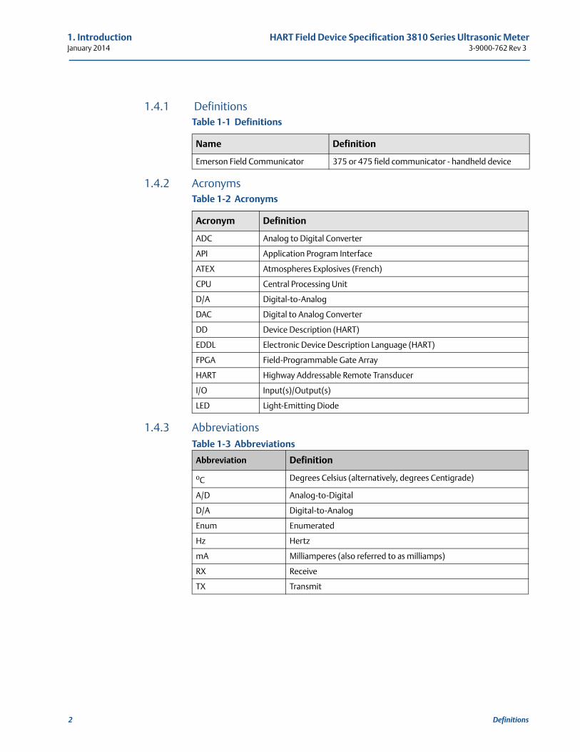
1.4.1 Definitions
1.4.2 Acronyms
1.4.3 AbbreviationsTable 1-3 Abbreviations
Table 1-1 Definitions
Name Definition
Emerson Field Communicator 375 or 475 field communicator - handheld device
Table 1-2 Acronyms
Acronym Definition
ADC Analog to Digital Converter
API Application Program Interface
ATEX Atmospheres Explosives (French)
CPU Central Processing Unit
D/A Digital-to-Analog
DAC Digital to Analog Converter
DD Device Description (HART)
EDDL Electronic Device Description Language (HART)
FPGA Field-Programmable Gate Array
HART Highway Addressable Remote Transducer
I/O Input(s)/Output(s)
LED Light-Emitting Diode
Abbreviation Definition
oC Degrees Celsius (alternatively, degrees Centigrade)
A/D Analog-to-Digital
D/A Digital-to-Analog
Enum Enumerated
Hz Hertz
mA Milliamperes (also referred to as milliamps)
RX Receive
TX Transmit
2 Definitions
HART Field Device Specification 3810 Series Ultrasonic Meter 1. Introduction3-9000-762 Rev 3 January 2014
References 3
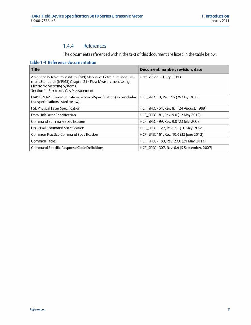
1.4.4 References
The documents referenced within the text of this document are listed in the table below:
Table 1-4 Reference documentation
Title Document number, revision, date
American Petroleum Institute (API) Manual of Petroleum Measure-ment Standards (MPMS) Chapter 21 - Flow Measurement Using Electronic Metering Systems Section 1 - Electronic Gas Measurement
First Edition, 01-Sep-1993
HART SMART Communications Protocol Specification (also includes the specifications listed below)
HCF_SPEC 13, Rev. 7.5 (29 May, 2013)
FSK Physical Layer Specification HCF_SPEC - 54, Rev. 8.1 (24 August, 1999)
Data Link Layer Specification HCF_SPEC - 81, Rev. 9.0 (12 May 2012)
Command Summary Specification HCF_SPEC - 99, Rev. 9.0 (23 July, 2007)
Universal Command Specification HCF_SPEC - 127, Rev. 7.1 (10 May, 2008)
Common Practice Command Specification HCF_SPEC-151, Rev. 10.0 (22 June 2012)
Common Tables HCF_SPEC - 183, Rev. 23.0 (29 May, 2013)
Command Specific Response Code Definitions HCF_SPEC - 307, Rev. 6.0 (5 September, 2007)
1. Introduction HART Field Device Specification 3810 Series Ultrasonic MeterJanuary 2014 3-9000-762 Rev 3
4 References
HART Field Device Specification 3810 Series Ultrasonic Meter 2. Device identification3-9000-762 Rev 3 January 2014
21
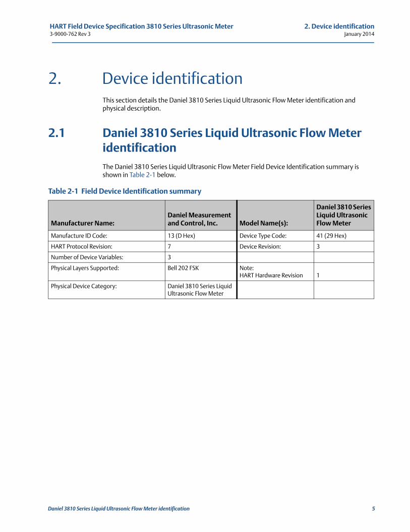
2. Device identificationThis section details the Daniel 3810 Series Liquid Ultrasonic Flow Meter identification and physical description.
2.1 Daniel 3810 Series Liquid Ultrasonic Flow Meter identificationThe Daniel 3810 Series Liquid Ultrasonic Flow Meter Field Device Identification summary is shown in Table 2-1 below.
Table 2-1 Field Device Identification summary
Manufacturer Name:Daniel Measurement and Control, Inc. Model Name(s):
Daniel 3810 Series Liquid Ultrasonic Flow Meter
Manufacture ID Code: 13 (D Hex) Device Type Code: 41 (29 Hex)
HART Protocol Revision: 7 Device Revision: 3
Number of Device Variables: 3
Physical Layers Supported: Bell 202 FSK Note: HART Hardware Revision 1
Physical Device Category: Daniel 3810 Series Liquid Ultrasonic Flow Meter
Daniel 3810 Series Liquid Ultrasonic Flow Meter identification 5
2. Device identification HART Field Device Specification 3810 Series Ultrasonic MeterJanuary 2014 3-9000-762 Rev 3
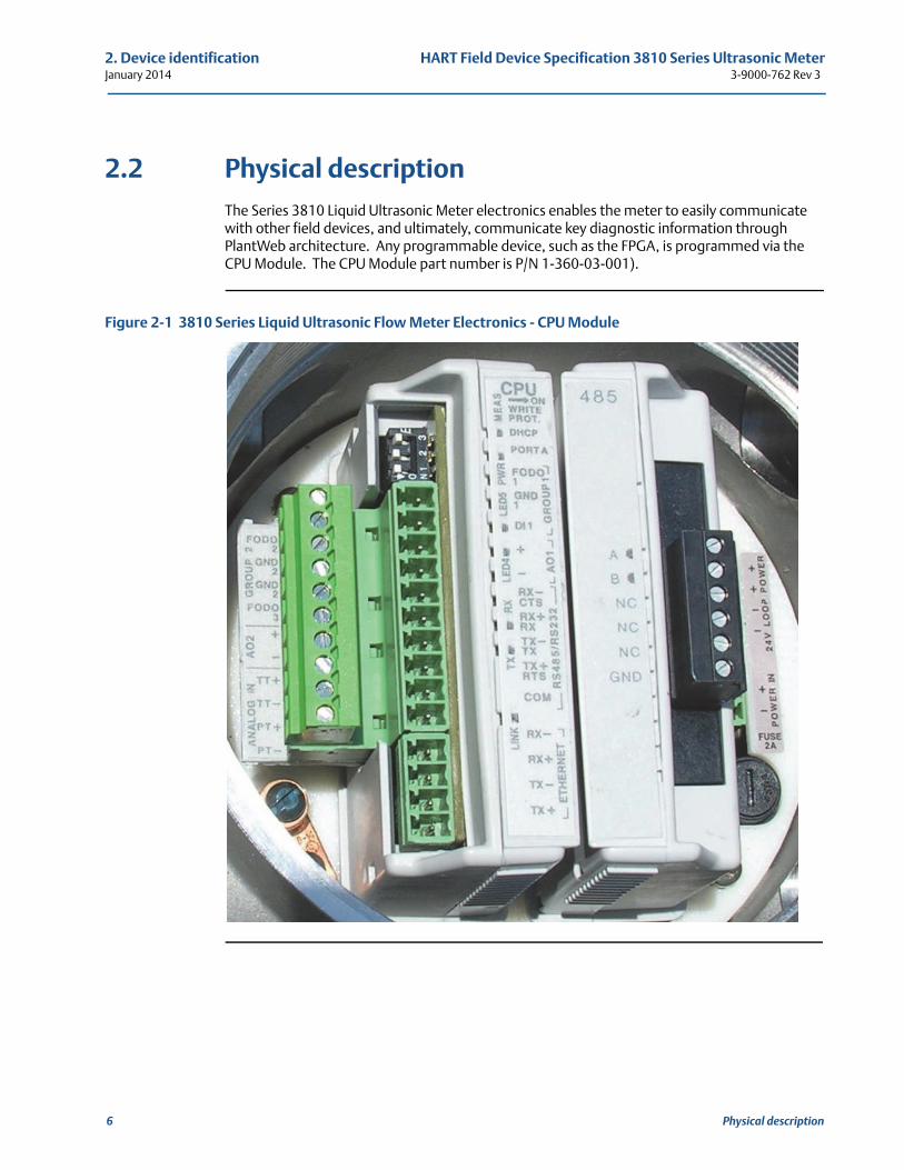
2.2 Physical descriptionThe Series 3810 Liquid Ultrasonic Meter electronics enables the meter to easily communicate with other field devices, and ultimately, communicate key diagnostic information through PlantWeb architecture. Any programmable device, such as the FPGA, is programmed via the CPU Module. The CPU Module part number is P/N 1-360-03-001).
Figure 2-1 3810 Series Liquid Ultrasonic Flow Meter Electronics - CPU Module
6 Physical description
HART Field Device Specification 3810 Series Ultrasonic Meter 3. Product overview3-9000-762 Rev 3 January 2014
3. Product overviewThis section specifies the purpose and application of the Daniel 3810 Series Liquid Ultrasonic Flow Meter for HART communications.
3.1 Device function, purpose and featuresThe Daniel 3810 Series Liquid Ultrasonic Flow Meter enables communication with other field devices, and ultimately, communicates key diagnostic information through the PlantWeb® architecture.
All analog inputs and outputs are isolated from each other and isolated from the system with a minimum isolation of 500 V.
3.2 Process connectionsThe Daniel 3810 Series Liquid Ultrasonic Flow Meter’s electronics (the firmware, CPU module and the Acquisition module) allows communications with other field devices.
3.3 External interfaces (electrical and non-electrical)Any pressure and/or temperature input read via the Daniel 3810 Series Liquid Ultrasonic Flow Meter is configured using a hand-held communicator (e.g., Emerson's 375 Field Communicator) and not via the meter such as for device address, device tag, limits, and units.
The Daniel 3810 Series Liquid Ultrasonic Flow Meter is compliant with Asset Management Solutions, AMSTM Device Manager, software applications that provides operator interface between a HART enabled field device and a remote PC.
3.4 Other required equipmentAn RS-232C/RS-485 (half duplex) serial communication port for Modbus communication is provided on Port A
Any programmable device on the Daniel 3810 Series Liquid Ultrasonic Flow Meter (such as a FPGA) is programmed via the CPU Module.
Device function, purpose and features 7
3. Product overview HART Field Device Specification 3810 Series Ultrasonic MeterJanuary 2014 3-9000-762 Rev 3
8 Other required equipment
HART Field Device Specification 3810 Series Ultrasonic Meter 4. Product interfaces3-9000-762 Rev 3 January 2014
4
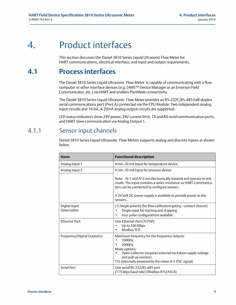
4. Product interfacesThis section discusses the Daniel 3810 Series Liquid Ultrasonic Flow Meter for HART communications, electrical interface, and input and output requirements.
4.1 Process interfacesThe Daniel 3810 Series Liquid Ultrasonic Flow Meter is capable of communicating with a flow computer or other interface devices (e.g. (AMSTM Device Manager or an Emerson Field Communicator, etc.) via HART and enables PlantWeb connectivity.
The Daniel 3810 Series Liquid Ultrasonic Flow Meter provides an RS-232C/RS-485 half-duplex serial communications port (Port A) connected via the CPU Module. Two independent analog input circuits and 16-bit, 4-20mA analog output circuits are supported.
LED status indicators show 24V power, 24V current limit, TX and RX serial communication ports, and HART slave communication via Analog Output 1.
4.1.1 Sensor input channelsDaniel 3810 Series Liquid Ultrasonic Flow Meters supports analog and discrete inputs as shown below.
Name Functional description
Analog Input 1 4 mA- 20 mA Input for temperature device
Analog Input 2 4 mA- 20 mA Input for pressure device
Note: AI-1 and AI-2 are electronically isolated and operate in sink mode. The input contains a series resistance so HART Communica-tors can be connected to configure sensors.
A 24 Volt DC power supply is available to provide power to the sensors.
Digital Input(Selectable)
(1) Single polarity (for flow calibration gating - contact closure)• Single input for starting and stopping• Four pulse configurations available
Ethernet Port One Ethernet Port (TCP/IP)• Up to 100 Mbps • Modbus TCP
Frequency/Digital Output(s) Maximum frequency for the frequency outputs• 1000Hz• 5000HzMode options:• Open Collector (requires external excitation supply voltage
and pull-up resistor)TTL (internally powered by the meter 0-5 VDC signal)
Serial Port One serial RS-232/RS-485 port (115 kbps baud rate) (Modbus RTU/ASCII)
Process interfaces 9
4. Product interfaces HART Field Device Specification 3810 Series Ultrasonic MeterJanuary 2014 3-9000-762 Rev 3
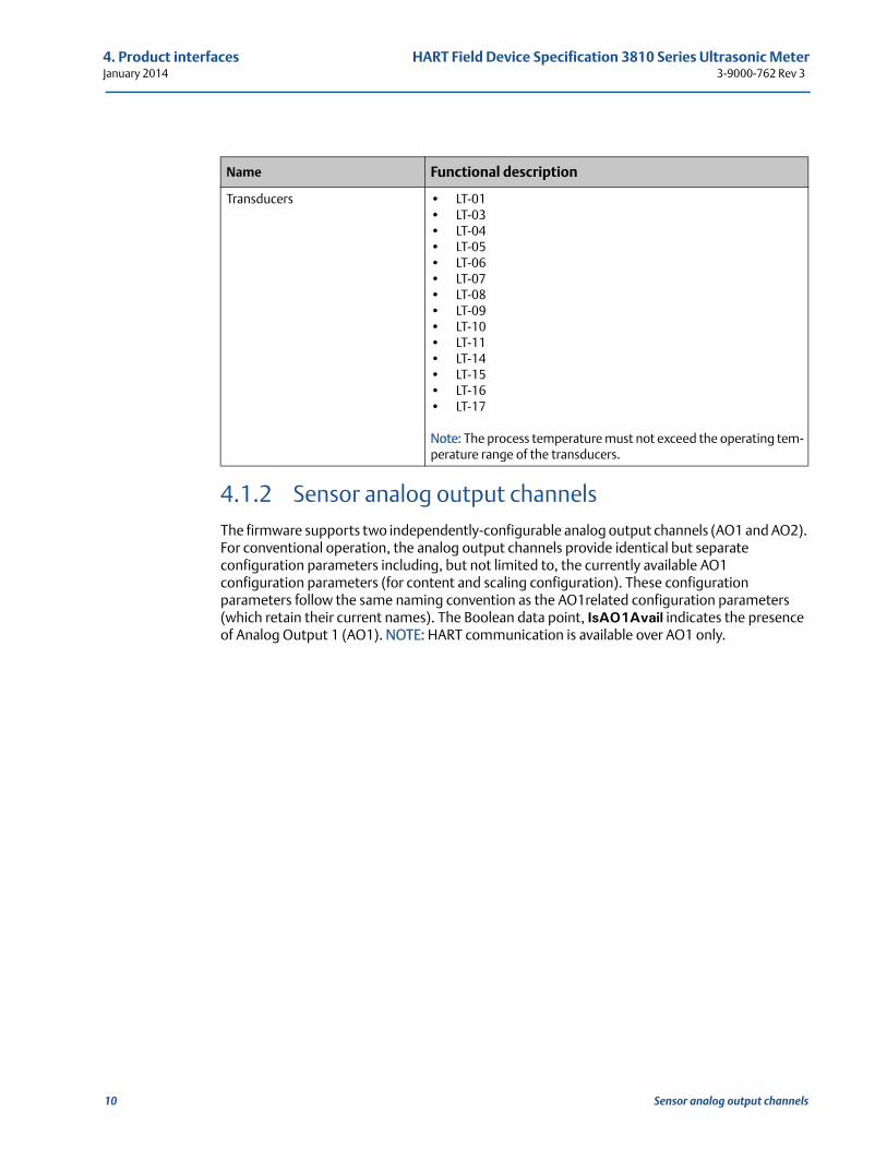
4.1.2 Sensor analog output channelsThe firmware supports two independently-configurable analog output channels (AO1 and AO2). For conventional operation, the analog output channels provide identical but separate configuration parameters including, but not limited to, the currently available AO1 configuration parameters (for content and scaling configuration). These configuration parameters follow the same naming convention as the AO1related configuration parameters (which retain their current names). The Boolean data point, IsAO1Avail indicates the presence of Analog Output 1 (AO1). NOTE: HART communication is available over AO1 only.
Transducers • LT-01• LT-03• LT-04• LT-05• LT-06• LT-07• LT-08• LT-09• LT-10• LT-11• LT-14• LT-15• LT-16• LT-17
Note: The process temperature must not exceed the operating tem-perature range of the transducers.
Name Functional description
10 Sensor analog output channels
HART Field Device Specification 3810 Series Ultrasonic Meter 4. Product interfaces3-9000-762 Rev 3 January 2014
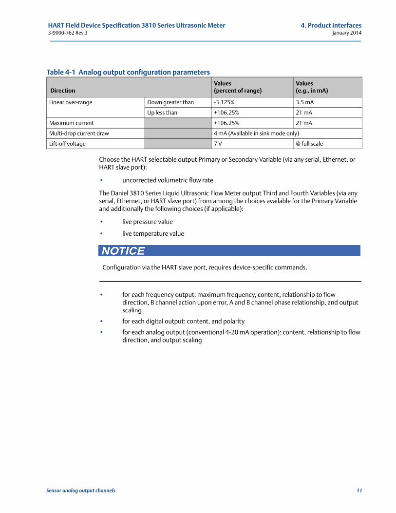
Table 4-1 Analog output configuration parameters
Choose the HART selectable output Primary or Secondary Variable (via any serial, Ethernet, or HART slave port):
• uncorrected volumetric flow rate
The Daniel 3810 Series Liquid Ultrasonic Flow Meter output Third and Fourth Variables (via any serial, Ethernet, or HART slave port) from among the choices available for the Primary Variable and additionally the following choices (if applicable):
• live pressure value
• live temperature value
• for each frequency output: maximum frequency, content, relationship to flow direction, B channel action upon error, A and B channel phase relationship, and output scaling
• for each digital output: content, and polarity
• for each analog output (conventional 4-20 mA operation): content, relationship to flow direction, and output scaling
DirectionValues(percent of range)
Values (e.g., in mA)
Linear over-range Down greater than -3.125% 3.5 mA
Up less than +106.25% 21 mA
Maximum current +106.25% 21 mA
Multi-drop current draw 4 mA (Available in sink mode only)
Lift-off voltage 7 V @ full scale
Configuration via the HART slave port, requires device-specific commands.
Sensor analog output channels 11
4. Product interfaces HART Field Device Specification 3810 Series Ultrasonic MeterJanuary 2014 3-9000-762 Rev 3
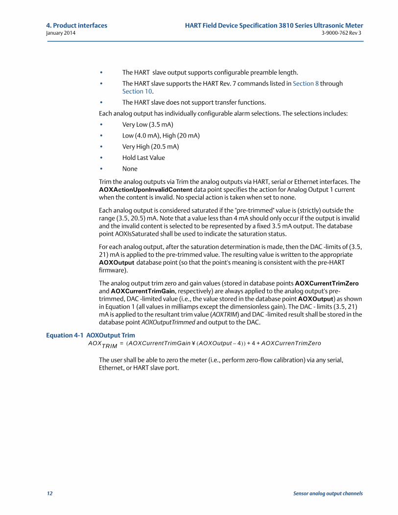
• The HART slave output supports configurable preamble length.
• The HART slave supports the HART Rev. 7 commands listed in Section 8 through Section 10.
• The HART slave does not support transfer functions.
Each analog output has individually configurable alarm selections. The selections includes:
• Very Low (3.5 mA)
• Low (4.0 mA), High (20 mA)
• Very High (20.5 mA)
• Hold Last Value
• None
Trim the analog outputs via Trim the analog outputs via HART, serial or Ethernet interfaces. The AOXActionUponInvalidContent data point specifies the action for Analog Output 1 current when the content is invalid. No special action is taken when set to none.
Each analog output is considered saturated if the "pre-trimmed" value is (strictly) outside the range (3.5, 20.5) mA. Note that a value less than 4 mA should only occur if the output is invalid and the invalid content is selected to be represented by a fixed 3.5 mA output. The database point AOXIsSaturated shall be used to indicate the saturation status.
For each analog output, after the saturation determination is made, then the DAC -limits of (3.5, 21) mA is applied to the pre-trimmed value. The resulting value is written to the appropriate AOXOutput database point (so that the point's meaning is consistent with the pre-HART firmware).
The analog output trim zero and gain values (stored in database points AOXCurrentTrimZero and AOXCurrentTrimGain, respectively) are always applied to the analog output's pre-trimmed, DAC -limited value (i.e., the value stored in the database point AOXOutput) as shown in Equation 1 (all values in milliamps except the dimensionless gain). The DAC - limits (3.5, 21) mA is applied to the resultant trim value (AOXTRIM) and DAC -limited result shall be stored in the database point AOXOutputTrimmed and output to the DAC.
Equation 4-1 AOXOutput Trim
The user shall be able to zero the meter (i.e., perform zero-flow calibration) via any serial, Ethernet, or HART slave port.
AOXTRIM AOXCurrentTrimGain AOXOutput 4–( )¥( ) 4 AOXCurrenTrimZero+ +=
12 Sensor analog output channels
HART Field Device Specification 3810 Series Ultrasonic Meter 4. Product interfaces3-9000-762 Rev 3 January 2014
Time Stamp 13
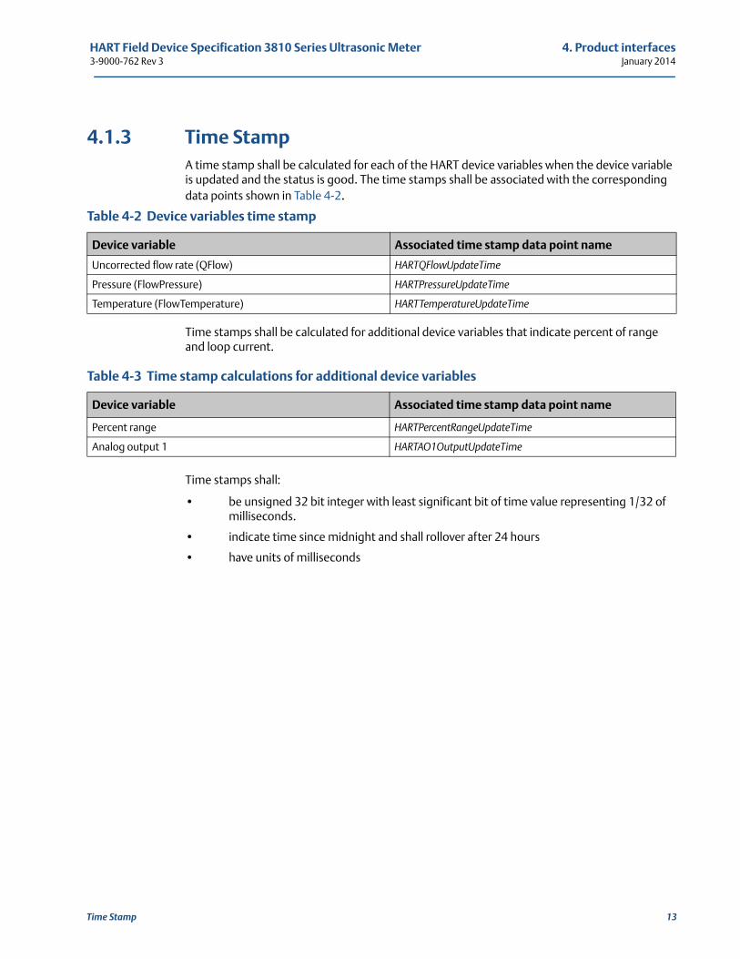
4.1.3 Time StampA time stamp shall be calculated for each of the HART device variables when the device variable is updated and the status is good. The time stamps shall be associated with the corresponding data points shown in Table 4-2.
Time stamps shall be calculated for additional device variables that indicate percent of range and loop current.
Time stamps shall:
• be unsigned 32 bit integer with least significant bit of time value representing 1/32 of milliseconds.
• indicate time since midnight and shall rollover after 24 hours
• have units of milliseconds
Table 4-2 Device variables time stamp
Device variable Associated time stamp data point name
Uncorrected flow rate (QFlow) HARTQFlowUpdateTime
Pressure (FlowPressure) HARTPressureUpdateTime
Temperature (FlowTemperature) HARTTemperatureUpdateTime
Table 4-3 Time stamp calculations for additional device variables
Device variable Associated time stamp data point name
Percent range HARTPercentRangeUpdateTime
Analog output 1 HARTAO1OutputUpdateTime

4. Product interfaces HART Field Device Specification 3810 Series Ultrasonic MeterJanuary 2014 3-9000-762 Rev 3
14 Time Stamp
HART Field Device Specification 3810 Series Ultrasonic Meter 5. Device variables3-9000-762 Rev 3 January 2014
51
5. Device variablesThe Daniel 3810 Series Liquid Ultrasonic Flow Meter does not use Device Family commands.
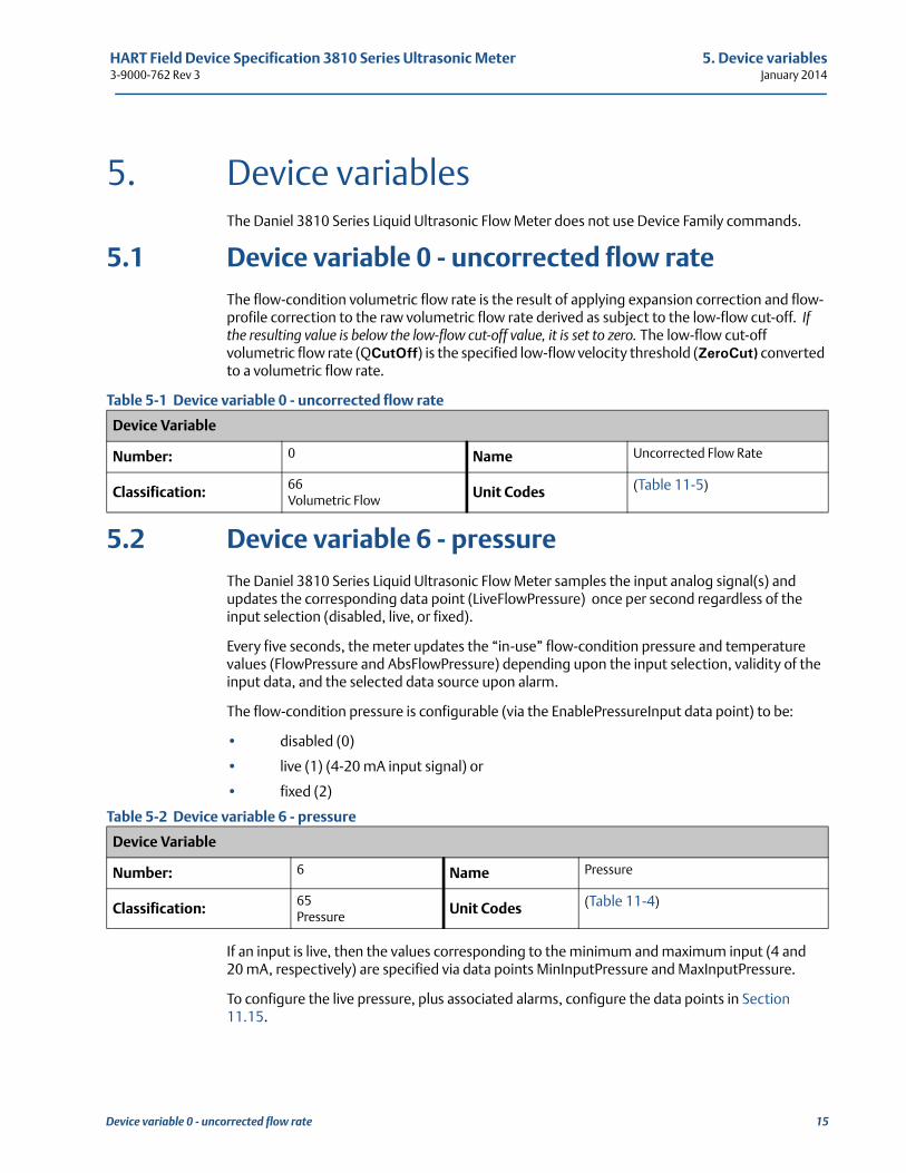
5.1 Device variable 0 - uncorrected flow rateThe flow-condition volumetric flow rate is the result of applying expansion correction and flow-profile correction to the raw volumetric flow rate derived as subject to the low-flow cut-off. If the resulting value is below the low-flow cut-off value, it is set to zero. The low-flow cut-off volumetric flow rate (QCutOff) is the specified low-flow velocity threshold (ZeroCut) converted to a volumetric flow rate.
Table 5-1 Device variable 0 - uncorrected flow rate
5.2 Device variable 6 - pressureThe Daniel 3810 Series Liquid Ultrasonic Flow Meter samples the input analog signal(s) and updates the corresponding data point (LiveFlowPressure) once per second regardless of the input selection (disabled, live, or fixed).
Every five seconds, the meter updates the “in-use” flow-condition pressure and temperature values (FlowPressure and AbsFlowPressure) depending upon the input selection, validity of the input data, and the selected data source upon alarm.
The flow-condition pressure is configurable (via the EnablePressureInput data point) to be:
• disabled (0)
• live (1) (4-20 mA input signal) or
• fixed (2)
Table 5-2 Device variable 6 - pressure
If an input is live, then the values corresponding to the minimum and maximum input (4 and 20 mA, respectively) are specified via data points MinInputPressure and MaxInputPressure.
To configure the live pressure, plus associated alarms, configure the data points in Section 11.15.
Device Variable
Number: 0 Name Uncorrected Flow Rate
Classification: 66Volumetric Flow
Unit Codes (Table 11-5)
Device Variable
Number: 6 Name Pressure
Classification: 65Pressure
Unit Codes (Table 11-4)
Device variable 0 - uncorrected flow rate 15
5. Device variables HART Field Device Specification 3810 Series Ultrasonic MeterJanuary 2014 3-9000-762 Rev 3
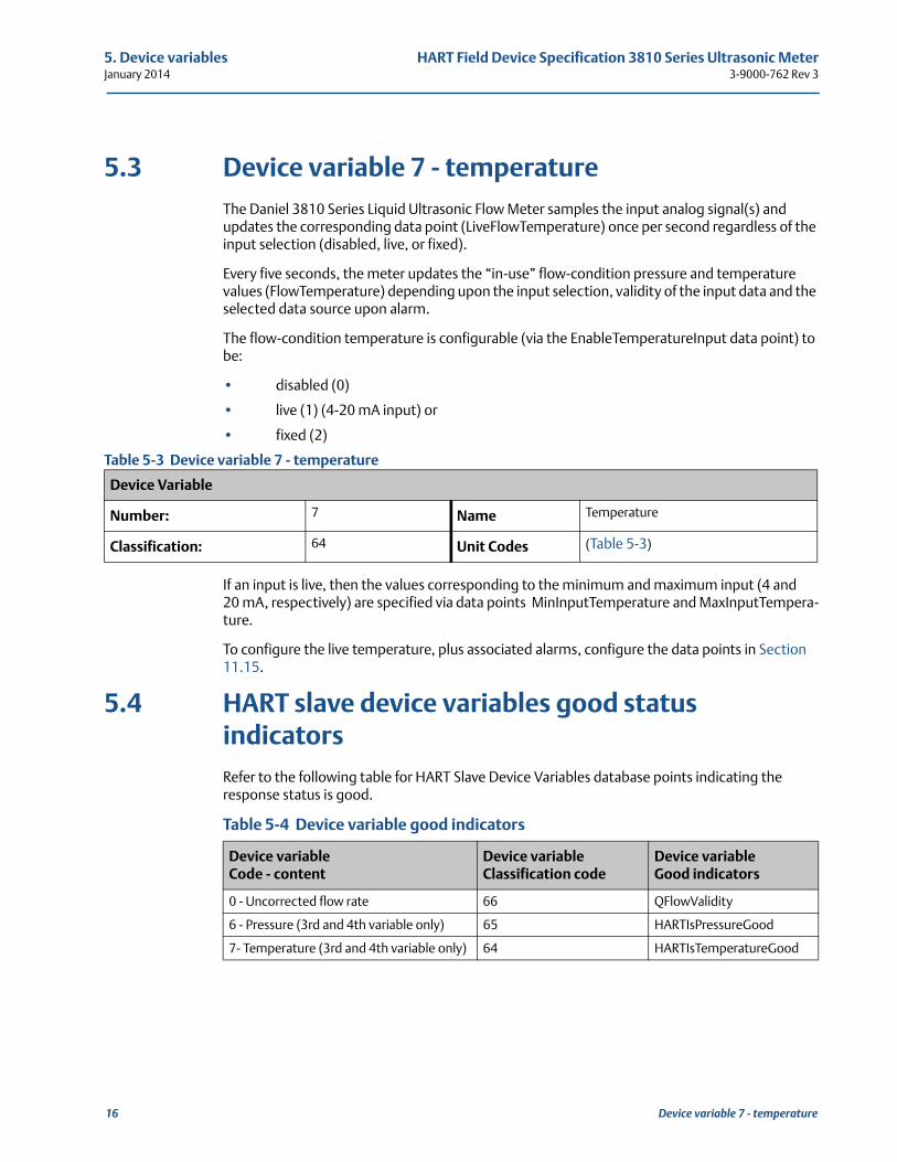
5.3 Device variable 7 - temperatureThe Daniel 3810 Series Liquid Ultrasonic Flow Meter samples the input analog signal(s) and updates the corresponding data point (LiveFlowTemperature) once per second regardless of the input selection (disabled, live, or fixed).
Every five seconds, the meter updates the “in-use” flow-condition pressure and temperature values (FlowTemperature) depending upon the input selection, validity of the input data and the selected data source upon alarm.
The flow-condition temperature is configurable (via the EnableTemperatureInput data point) to be:
• disabled (0)
• live (1) (4-20 mA input) or
• fixed (2)
Table 5-3 Device variable 7 - temperature
If an input is live, then the values corresponding to the minimum and maximum input (4 and 20 mA, respectively) are specified via data points MinInputTemperature and MaxInputTempera-ture.
To configure the live temperature, plus associated alarms, configure the data points in Section 11.15.
5.4 HART slave device variables good status indicatorsRefer to the following table for HART Slave Device Variables database points indicating the response status is good.
Device Variable
Number: 7 Name Temperature
Classification: 64 Unit Codes (Table 5-3)
Table 5-4 Device variable good indicators
Device variable Code - content
Device variable Classification code
Device variable Good indicators
0 - Uncorrected flow rate 66 QFlowValidity
6 - Pressure (3rd and 4th variable only) 65 HARTIsPressureGood
7- Temperature (3rd and 4th variable only) 64 HARTIsTemperatureGood
16 Device variable 7 - temperature
HART Field Device Specification 3810 Series Ultrasonic Meter 6. Dynamic variables3-9000-762 Rev 3 January 2014
61
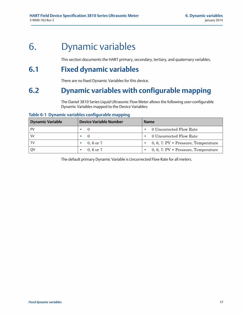
6. Dynamic variablesThis section documents the HART primary, secondary, tertiary, and quaternary variables.
6.1 Fixed dynamic variablesThere are no fixed Dynamic Variables for this device.
6.2 Dynamic variables with configurable mappingThe Daniel 3810 Series Liquid Ultrasonic Flow Meter allows the following user-configurable Dynamic Variables mapped to the Device Variables:
Table 6-1 Dynamic variables configurable mapping
The default primary Dynamic Variable is Uncorrected Flow Rate for all meters.
Dynamic Variable Device Variable Number Name
PV • 0 • 0 Uncorrected Flow Rate
SV • 0 • 0 Uncorrected Flow Rate
TV • 0, 6 or 7 • 0, 6, 7: PV + Pressure, Temperature
QV • 0, 6 or 7 • 0, 6, 7: PV + Pressure, Temperature
Fixed dynamic variables 17
6. Dynamic variables HART Field Device Specification 3810 Series Ultrasonic MeterJanuary 2014 3-9000-762 Rev 3
18 Dynamic variables with configurable mapping
HART Field Device Specification 3810 Series Ultrasonic Meter 7. Status information3-9000-762 Rev 3 January 2014
71
7. Status informationThis section documents the HART primary, secondary, tertiary, and quaternary variables for Daniel Liquid Ultrasonic Flow Meters.
The meter status information is derived from Boolean database points. For host display purposes, the status information is divided into three categories:
• Failed - indications that the meter is not working properly and has lost measurement
• Maintenance - indications that the meter requires operator intervention
• Advisory - indications that the meter has information but is still measuring flow and does not require operator intervention
The meter uses the following mechanisms for communicating the status information to the host system:
• the Device Status Byte sent with every slave response,
• the Read Additional Device Status Universal Command 48 (see Section 7.2)
• the device-specific command for reading detailed status information Command 140 (Section 10.1.13).
Device-Specific Command 141 (Section 10.1.14) is used to acknowledge status Boolean database points that require acknowledgement.
Alerts are sorted into three groups: Failed, Maintenance, and Advisory. These groups are displayed in AMSTM Device Manager and communicated via Universal Command 48 (see Section 7.2) unless it is indicated via the device status byte.
The database point mapping for the Device Status Byte is shown in Table 7-1. Command 48 database point mapping is shown in Table 7-2. Note that for Command 48, only the first 16 bytes (numbered 0 through 15) shall be sent by the HART Slave. Additional Device Status information is communicated via Device-Specific Command 140 (illustrated in the command definition in Section 10.1.13).
19
7. Status information HART Field Device Specification 3810 Series Ultrasonic MeterJanuary 2014 3-9000-762 Rev 3
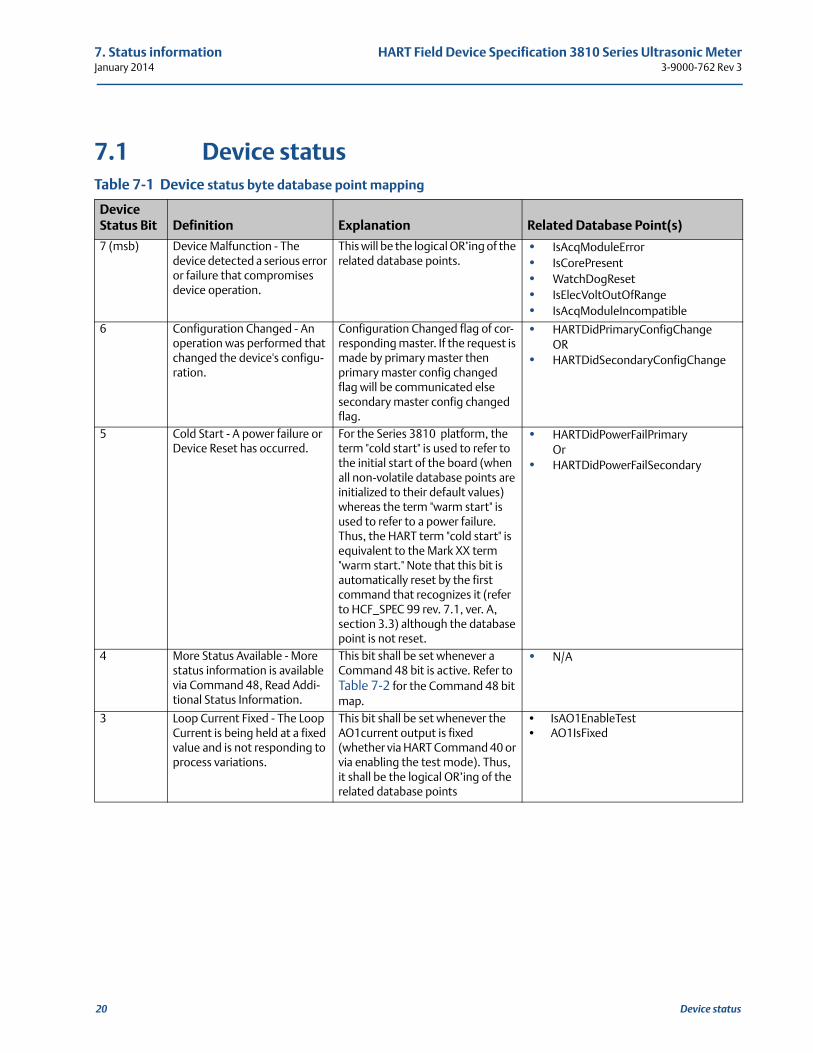
7.1 Device statusTable 7-1 Device status byte database point mapping
Device Status Bit Definition Explanation Related Database Point(s)
7 (msb) Device Malfunction - The device detected a serious error or failure that compromises device operation.
This will be the logical OR’ing of the related database points.
• IsAcqModuleError• IsCorePresent• WatchDogReset• IsElecVoltOutOfRange• IsAcqModuleIncompatible
6 Configuration Changed - An operation was performed that changed the device's configu-ration.
Configuration Changed flag of cor-responding master. If the request is made by primary master then primary master config changed flag will be communicated else secondary master config changed flag.
• HARTDidPrimaryConfigChangeOR
• HARTDidSecondaryConfigChange
5 Cold Start - A power failure or Device Reset has occurred.
For the Series 3810 platform, the term "cold start" is used to refer to the initial start of the board (when all non-volatile database points are initialized to their default values) whereas the term "warm start" is used to refer to a power failure. Thus, the HART term "cold start" is equivalent to the Mark XX term "warm start." Note that this bit is automatically reset by the first command that recognizes it (refer to HCF_SPEC 99 rev. 7.1, ver. A, section 3.3) although the database point is not reset.
• HARTDidPowerFailPrimaryOr
• HARTDidPowerFailSecondary
4 More Status Available - More status information is available via Command 48, Read Addi-tional Status Information.
This bit shall be set whenever a Command 48 bit is active. Refer to Table 7-2 for the Command 48 bit map.
• N/A
3 Loop Current Fixed - The Loop Current is being held at a fixed value and is not responding to process variations.
This bit shall be set whenever the AO1current output is fixed (whether via HART Command 40 or via enabling the test mode). Thus, it shall be the logical OR’ing of the related database points
• IsAO1EnableTest• AO1IsFixed
20 Device status
HART Field Device Specification 3810 Series Ultrasonic Meter 7. Status information3-9000-762 Rev 3 January 2014
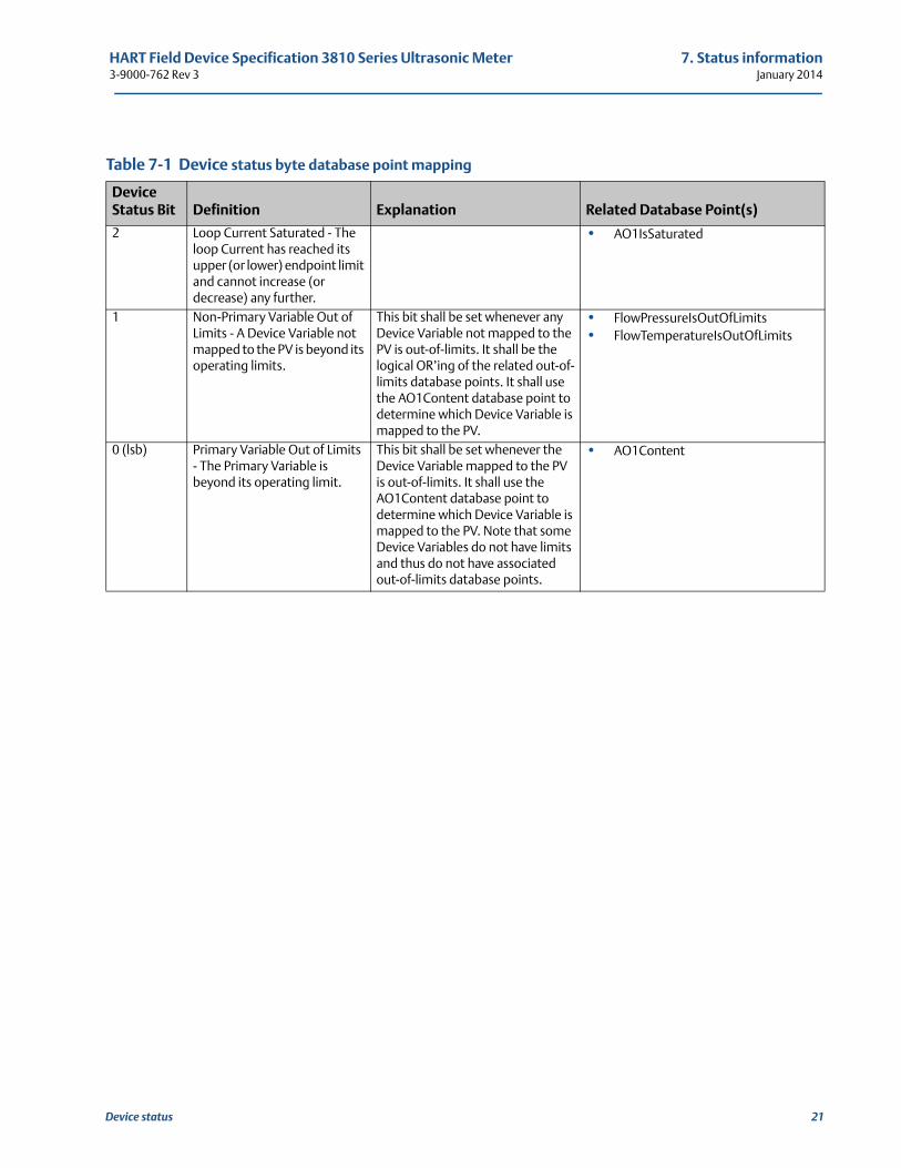
2 Loop Current Saturated - The loop Current has reached its upper (or lower) endpoint limit and cannot increase (or decrease) any further.
• AO1IsSaturated
1 Non-Primary Variable Out of Limits - A Device Variable not mapped to the PV is beyond its operating limits.
This bit shall be set whenever any Device Variable not mapped to the PV is out-of-limits. It shall be the logical OR’ing of the related out-of-limits database points. It shall use the AO1Content database point to determine which Device Variable is mapped to the PV.
• FlowPressureIsOutOfLimits• FlowTemperatureIsOutOfLimits
0 (lsb) Primary Variable Out of Limits - The Primary Variable is beyond its operating limit.
This bit shall be set whenever the Device Variable mapped to the PV is out-of-limits. It shall use the AO1Content database point to determine which Device Variable is mapped to the PV. Note that some Device Variables do not have limits and thus do not have associated out-of-limits database points.
• AO1Content
Table 7-1 Device status byte database point mapping
Device Status Bit Definition Explanation Related Database Point(s)
Device status 21
7. Status information HART Field Device Specification 3810 Series Ultrasonic MeterJanuary 2014 3-9000-762 Rev 3
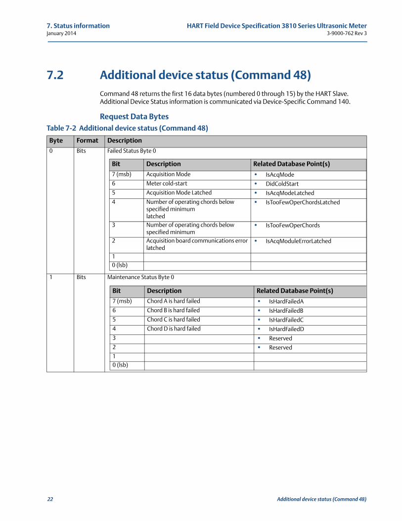
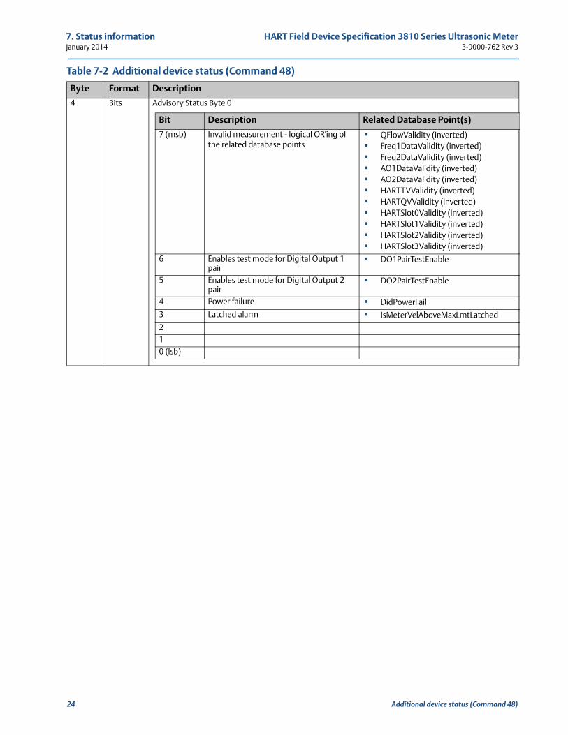
7.2 Additional device status (Command 48)Command 48 returns the first 16 data bytes (numbered 0 through 15) by the HART Slave. Additional Device Status information is communicated via Device-Specific Command 140.
Request Data BytesTable 7-2 Additional device status (Command 48)
Byte Format Description
0 Bits Failed Status Byte 0
1 Bits Maintenance Status Byte 0
Bit Description Related Database Point(s)
7 (msb) Acquisition Mode • IsAcqMode
6 Meter cold-start • DidColdStart
5 Acquisition Mode Latched • IsAcqModeLatched
4 Number of operating chords below specified minimumlatched
• IsTooFewOperChordsLatched
3 Number of operating chords below specified minimum
• IsTooFewOperChords
2 Acquisition board communications error latched
• IsAcqModuleErrorLatched
10 (lsb)
Bit Description Related Database Point(s)
7 (msb) Chord A is hard failed • IsHardFailedA
6 Chord B is hard failed • IsHardFailedB
5 Chord C is hard failed • IsHardFailedC
4 Chord D is hard failed • IsHardFailedD
3 • Reserved
2 • Reserved
10 (lsb)
22 Additional device status (Command 48)
HART Field Device Specification 3810 Series Ultrasonic Meter 7. Status information3-9000-762 Rev 3 January 2014
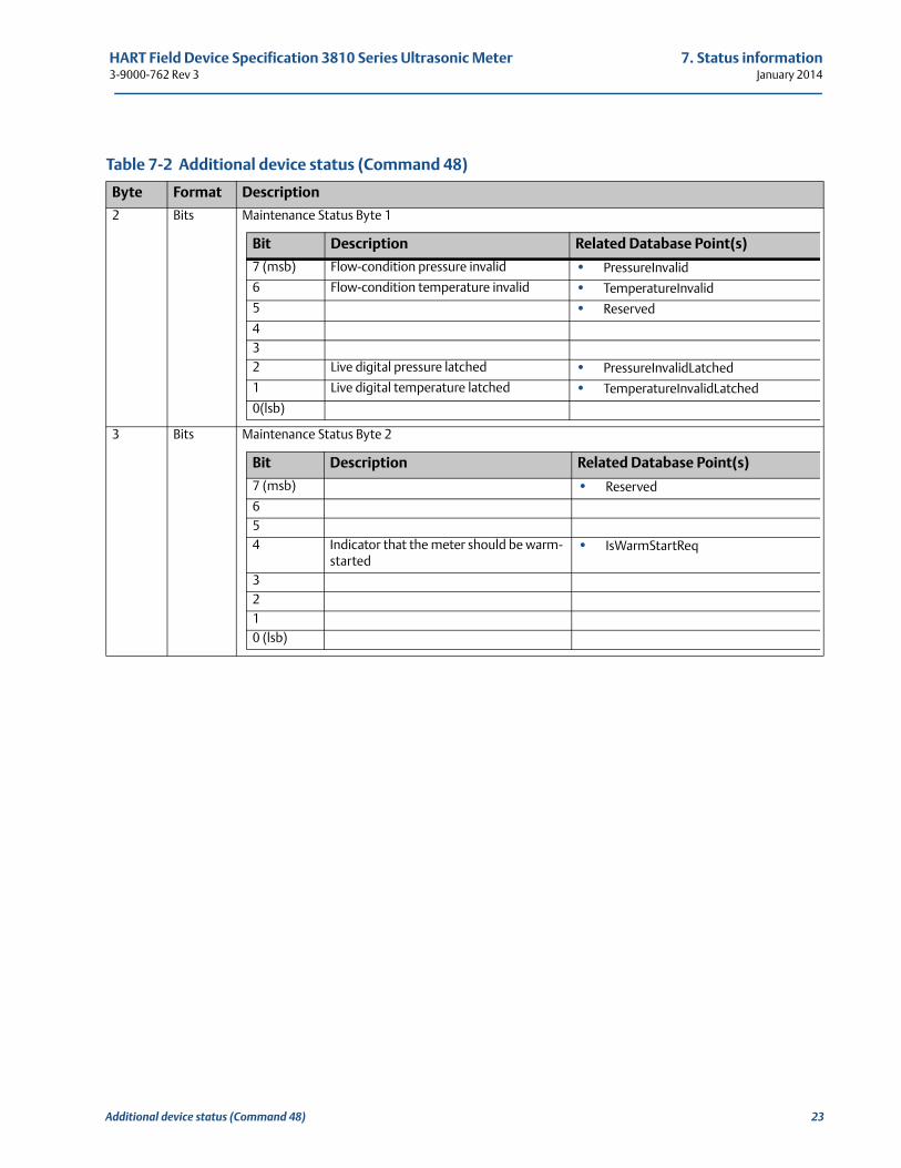
2 Bits Maintenance Status Byte 1
3 Bits Maintenance Status Byte 2
Table 7-2 Additional device status (Command 48)
Byte Format Description
Bit Description Related Database Point(s)
7 (msb) Flow-condition pressure invalid • PressureInvalid
6 Flow-condition temperature invalid • TemperatureInvalid
5 • Reserved
432 Live digital pressure latched • PressureInvalidLatched
1 Live digital temperature latched • TemperatureInvalidLatched
0(lsb)
Bit Description Related Database Point(s)
7 (msb) • Reserved
654 Indicator that the meter should be warm-
started• IsWarmStartReq
3210 (lsb)
Additional device status (Command 48) 23
7. Status information HART Field Device Specification 3810 Series Ultrasonic MeterJanuary 2014 3-9000-762 Rev 3
4 Bits Advisory Status Byte 0
Table 7-2 Additional device status (Command 48)
Byte Format Description
Bit Description Related Database Point(s)
7 (msb) Invalid measurement - logical OR'ing of the related database points
• QFlowValidity (inverted)• Freq1DataValidity (inverted)• Freq2DataValidity (inverted)• AO1DataValidity (inverted)• AO2DataValidity (inverted)• HARTTVValidity (inverted)• HARTQVValidity (inverted)• HARTSlot0Validity (inverted)• HARTSlot1Validity (inverted)• HARTSlot2Validity (inverted)• HARTSlot3Validity (inverted)
6 Enables test mode for Digital Output 1 pair
• DO1PairTestEnable
5 Enables test mode for Digital Output 2 pair
• DO2PairTestEnable
4 Power failure • DidPowerFail
3 Latched alarm • IsMeterVelAboveMaxLmtLatched
210 (lsb)
24 Additional device status (Command 48)
HART Field Device Specification 3810 Series Ultrasonic Meter 7. Status information3-9000-762 Rev 3 January 2014
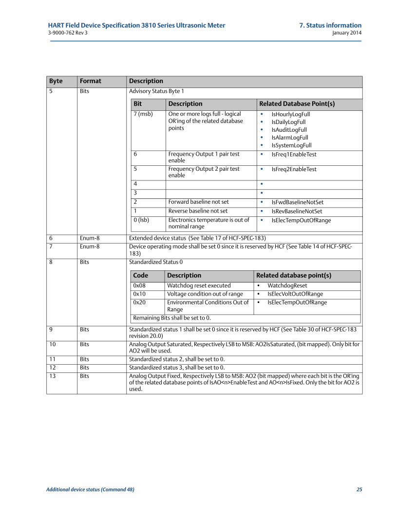
Byte Format Description
5 Bits Advisory Status Byte 1
6 Enum-8 Extended device status (See Table 17 of HCF-SPEC-183)7 Enum-8 Device operating mode shall be set 0 since it is reserved by HCF (See Table 14 of HCF-SPEC-
183)8 Bits Standardized Status 0
9 Bits Standardized status 1 shall be set 0 since it is reserved by HCF (See Table 30 of HCF-SPEC-183 revision 20.0)
10 Bits Analog Output Saturated, Respectively LSB to MSB: AO2IsSaturated, (bit mapped). Only bit for AO2 will be used.
11 Bits Standardized status 2, shall be set to 0.12 Bits Standardized status 3, shall be set to 0.13 Bits Analog Output Fixed, Respectively LSB to MSB: AO2 (bit mapped) where each bit is the OR'ing
of the related database points of IsAO<n>EnableTest and AO<n>IsFixed. Only the bit for AO2 is used.
Bit Description Related Database Point(s)
7 (msb) One or more logs full - logical OR'ing of the related database points
• IsHourlyLogFull• IsDailyLogFull• IsAuditLogFull• IsAlarmLogFull• IsSystemLogFull
6 Frequency Output 1 pair test enable
• IsFreq1EnableTest
5 Frequency Output 2 pair test enable
• IsFreq2EnableTest
4 •3 •2 Forward baseline not set • IsFwdBaselineNotSet
1 Reverse baseline not set • IsRevBaselineNotSet
0 (lsb) Electronics temperature is out of nominal range
• IsElecTempOutOfRange
Code Description Related database point(s)
0x08 Watchdog reset executed • WatchdogReset0x10 Voltage condition out of range • IsElecVoltOutOfRange0x20 Environmental Conditions Out of
Range• IsElecTempOutOfRange
Remaining Bits shall be set to 0.
Additional device status (Command 48) 25
7. Status information HART Field Device Specification 3810 Series Ultrasonic MeterJanuary 2014 3-9000-762 Rev 3
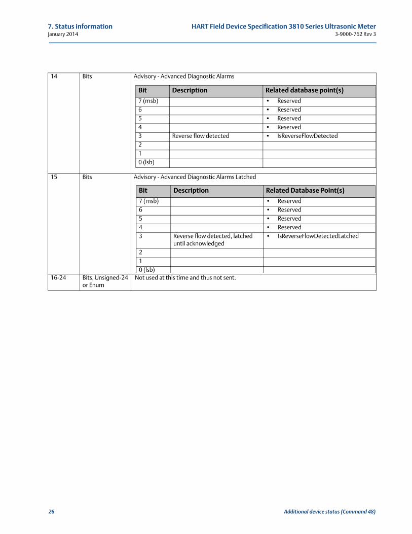
14 Bits Advisory - Advanced Diagnostic Alarms
15 Bits Advisory - Advanced Diagnostic Alarms Latched
16-24 Bits, Unsigned-24 or Enum
Not used at this time and thus not sent.
Bit Description Related database point(s)
7 (msb) • Reserved6 • Reserved5 • Reserved4 • Reserved3 Reverse flow detected • IsReverseFlowDetected210 (lsb)
Bit Description Related Database Point(s)
7 (msb) • Reserved6 • Reserved5 • Reserved4 • Reserved3 Reverse flow detected, latched
until acknowledged• IsReverseFlowDetectedLatched
2 10 (lsb)
26 Additional device status (Command 48)
HART Field Device Specification 3810 Series Ultrasonic Meter 8. Universal commands3-9000-762 Rev 3 January 2014
8
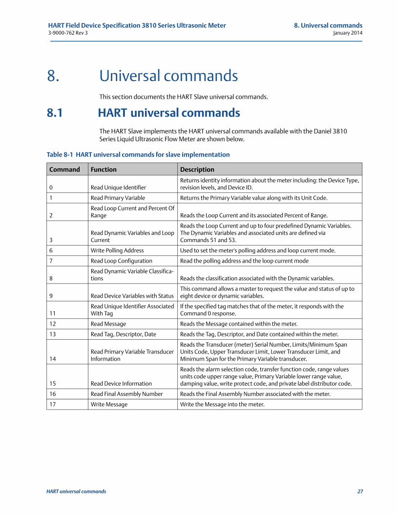
8. Universal commandsThis section documents the HART Slave universal commands.
8.1 HART universal commandsThe HART Slave implements the HART universal commands available with the Daniel 3810 Series Liquid Ultrasonic Flow Meter are shown below.
Table 8-1 HART universal commands for slave implementation
Command Function Description
0 Read Unique IdentifierReturns identity information about the meter including: the Device Type, revision levels, and Device ID.
1 Read Primary Variable Returns the Primary Variable value along with its Unit Code.
2Read Loop Current and Percent Of Range Reads the Loop Current and its associated Percent of Range.
3Read Dynamic Variables and Loop Current
Reads the Loop Current and up to four predefined Dynamic Variables. The Dynamic Variables and associated units are defined via Commands 51 and 53.
6 Write Polling Address Used to set the meter's polling address and loop current mode.
7 Read Loop Configuration Read the polling address and the loop current mode
8Read Dynamic Variable Classifica-tions Reads the classification associated with the Dynamic variables.
9 Read Device Variables with StatusThis command allows a master to request the value and status of up to eight device or dynamic variables.
11Read Unique Identifier Associated With Tag
If the specified tag matches that of the meter, it responds with the Command 0 response.
12 Read Message Reads the Message contained within the meter.
13 Read Tag, Descriptor, Date Reads the Tag, Descriptor, and Date contained within the meter.
14Read Primary Variable Transducer Information
Reads the Transducer (meter) Serial Number, Limits/Minimum Span Units Code, Upper Transducer Limit, Lower Transducer Limit, and Minimum Span for the Primary Variable transducer.
15 Read Device Information
Reads the alarm selection code, transfer function code, range values units code upper range value, Primary Variable lower range value, damping value, write protect code, and private label distributor code.
16 Read Final Assembly Number Reads the Final Assembly Number associated with the meter.
17 Write Message Write the Message into the meter.
HART universal commands 27
8. Universal commands HART Field Device Specification 3810 Series Ultrasonic MeterJanuary 2014 3-9000-762 Rev 3
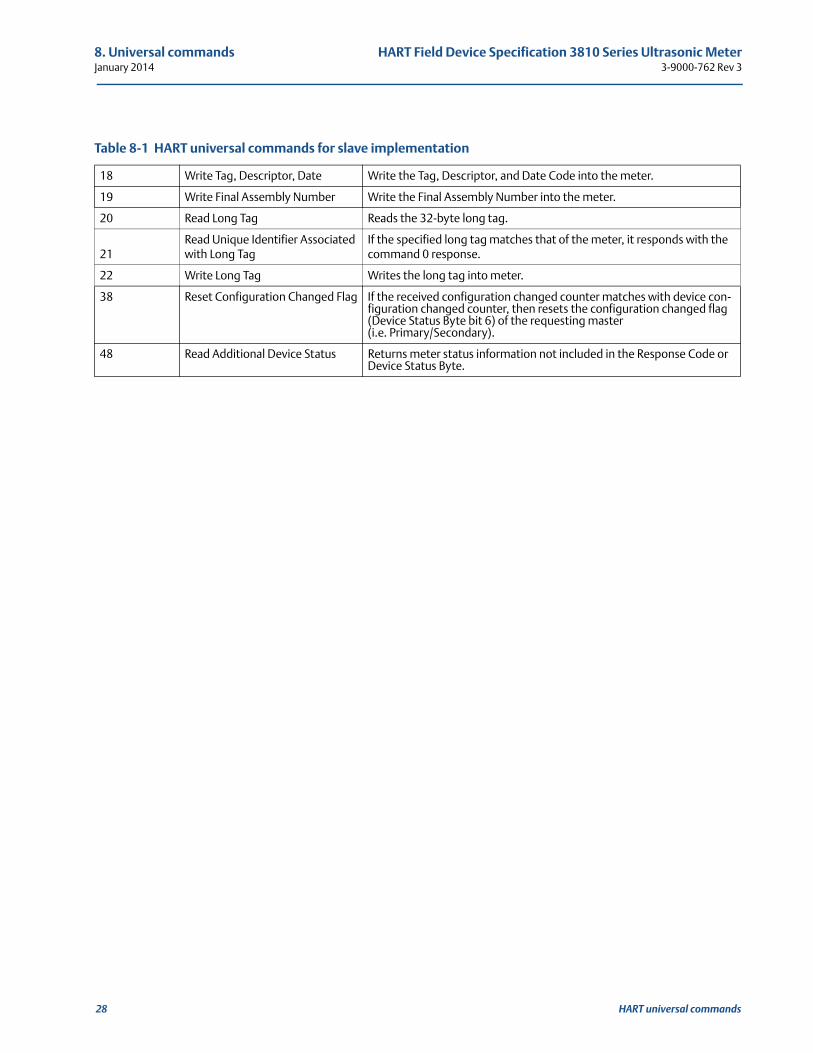
18 Write Tag, Descriptor, Date Write the Tag, Descriptor, and Date Code into the meter.
19 Write Final Assembly Number Write the Final Assembly Number into the meter.
20 Read Long Tag Reads the 32-byte long tag.
21Read Unique Identifier Associated with Long Tag
If the specified long tag matches that of the meter, it responds with the command 0 response.
22 Write Long Tag Writes the long tag into meter.
38 Reset Configuration Changed Flag If the received configuration changed counter matches with device con-figuration changed counter, then resets the configuration changed flag (Device Status Byte bit 6) of the requesting master(i.e. Primary/Secondary).
48 Read Additional Device Status Returns meter status information not included in the Response Code or Device Status Byte.
Table 8-1 HART universal commands for slave implementation
28 HART universal commands
HART Field Device Specification 3810 Series Ultrasonic Meter 9. Common-practice commands3-9000-762 Rev 3 January 2014
9
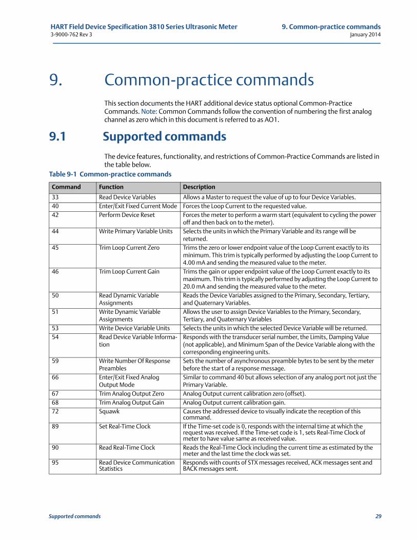
9. Common-practice commandsThis section documents the HART additional device status optional Common-Practice Commands. Note: Common Commands follow the convention of numbering the first analog channel as zero which in this document is referred to as AO1.
9.1 Supported commands
The device features, functionality, and restrictions of Common-Practice Commands are listed in the table below.
Table 9-1 Common-practice commands
Command Function Description
33 Read Device Variables Allows a Master to request the value of up to four Device Variables.40 Enter/Exit Fixed Current Mode Forces the Loop Current to the requested value.42 Perform Device Reset Forces the meter to perform a warm start (equivalent to cycling the power
off and then back on to the meter).44 Write Primary Variable Units Selects the units in which the Primary Variable and its range will be
returned.45 Trim Loop Current Zero Trims the zero or lower endpoint value of the Loop Current exactly to its
minimum. This trim is typically performed by adjusting the Loop Current to 4.00 mA and sending the measured value to the meter.
46 Trim Loop Current Gain Trims the gain or upper endpoint value of the Loop Current exactly to its maximum. This trim is typically performed by adjusting the Loop Current to 20.0 mA and sending the measured value to the meter.
50 Read Dynamic Variable Assignments
Reads the Device Variables assigned to the Primary, Secondary, Tertiary, and Quaternary Variables.
51 Write Dynamic Variable Assignments
Allows the user to assign Device Variables to the Primary, Secondary, Tertiary, and Quaternary Variables
53 Write Device Variable Units Selects the units in which the selected Device Variable will be returned.54 Read Device Variable Informa-
tionResponds with the transducer serial number, the Limits, Damping Value (not applicable), and Minimum Span of the Device Variable along with the corresponding engineering units.
59 Write Number Of Response Preambles
Sets the number of asynchronous preamble bytes to be sent by the meter before the start of a response message.
66 Enter/Exit Fixed Analog Output Mode
Similar to command 40 but allows selection of any analog port not just the Primary Variable.
67 Trim Analog Output Zero Analog Output current calibration zero (offset).68 Trim Analog Output Gain Analog Output current calibration gain.72 Squawk Causes the addressed device to visually indicate the reception of this
command.89 Set Real-Time Clock If the Time-set code is 0, responds with the internal time at which the
request was received. If the Time-set code is 1, sets Real-Time Clock of meter to have value same as received value.
90 Read Real-Time Clock Reads the Real-Time Clock including the current time as estimated by the meter and the last time the clock was set.
95 Read Device Communication Statistics
Responds with counts of STX messages received, ACK messages sent and BACK messages sent.
Supported commands 29
9. Common-practice commands HART Field Device Specification 3810 Series Ultrasonic MeterJanuary 2014 3-9000-762 Rev 3
9.2 Burst ModeThis device does not support burst mode.
9.3 Catch Device VariableThis device does not support catch device variable.
30 Burst Mode
HART Field Device Specification 3810 Series Ultrasonic Meter 10. Device-specific commands3-9000-762 Rev 3 January 2014
101
10. Device-specific commandsThis section documents the Device-Specific Commands implemented for the Daniel 3810 Series Liquid Ultrasonic Flow Meter.
10.1 Public, device-specific commandsThe Series 3810 Device-Specific Commands in each of the following subsections as defined by:
• command number and command name
• functional description
• command’s operation (i.e., read/write/command)
• request data (Byte stream position, data format and descriptions)
• response data (Byte stream position, data format and descriptions)
• Command-specific response codes
Public, device-specific commands 31
10. Device-specific commands HART Field Device Specification 3810 Series Ultrasonic MeterJanuary 2014 3-9000-762 Rev 3
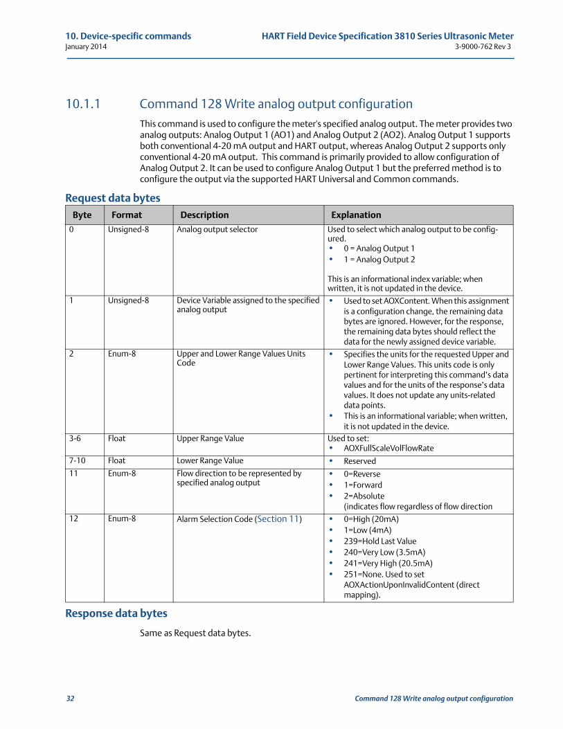
10.1.1 Command 128 Write analog output configurationThis command is used to configure the meter's specified analog output. The meter provides two analog outputs: Analog Output 1 (AO1) and Analog Output 2 (AO2). Analog Output 1 supports both conventional 4-20 mA output and HART output, whereas Analog Output 2 supports only conventional 4-20 mA output. This command is primarily provided to allow configuration of Analog Output 2. It can be used to configure Analog Output 1 but the preferred method is to configure the output via the supported HART Universal and Common commands.
Request data bytes
Response data bytes
Same as Request data bytes.
Byte Format Description Explanation
0 Unsigned-8 Analog output selector Used to select which analog output to be config-ured.• 0 = Analog Output 1• 1 = Analog Output 2
This is an informational index variable; when written, it is not updated in the device.
1 Unsigned-8 Device Variable assigned to the specified analog output
• Used to set AOXContent. When this assignment is a configuration change, the remaining data bytes are ignored. However, for the response, the remaining data bytes should reflect the data for the newly assigned device variable.
2 Enum-8 Upper and Lower Range Values Units Code
• Specifies the units for the requested Upper and Lower Range Values. This units code is only pertinent for interpreting this command’s data values and for the units of the response’s data values. It does not update any units-related data points.
• This is an informational variable; when written, it is not updated in the device.
3-6 Float Upper Range Value Used to set:• AOXFullScaleVolFlowRate
7-10 Float Lower Range Value • Reserved
11 Enum-8 Flow direction to be represented by specified analog output
• 0=Reverse• 1=Forward• 2=Absolute
(indicates flow regardless of flow direction12 Enum-8 Alarm Selection Code (Section 11) • 0=High (20mA)
• 1=Low (4mA)• 239=Hold Last Value• 240=Very Low (3.5mA)• 241=Very High (20.5mA)• 251=None. Used to set
AOXActionUponInvalidContent (direct mapping).
32 Command 128 Write analog output configuration
HART Field Device Specification 3810 Series Ultrasonic Meter 10. Device-specific commands3-9000-762 Rev 3 January 2014
Command 128 Write analog output configuration 33
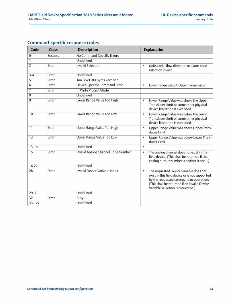
Command-specific response codes
Code Class Description Explanation
0 Success No Command-Specific Errors1 Undefined2 Error Invalid Selection • Units code, flow direction or alarm code
selection invalid.3-4 Error Undefined5 Error Too Few Data Bytes Received6 Error Device-Specific Command Error • Lower range value > Upper range value
7 Error In Write Protect Mode8 Undefined9 Error Lower Range Value Too High • Lower Range Value was above the Upper
Transducer Limit or some other physical device limitation is exceeded.
10 Error Lower Range Value Too Low • Lower Range Value was below the Lower Transducer Limit or some other physical device limitation is exceeded.
11 Error Upper Range Value Too High • Upper Range Value was above Upper Trans-ducer Limit.
12 Error Upper Range Value Too Low • Upper Range Value was below Lower Trans-ducer Limit.
13-14 Undefined •15 Error Invalid Analog Channel Code Number • The analog channel does not exist in this
field device. (This shall be returned if the analog output number is neither 0 nor 1.)
16-27 Undefined28 Error Invalid Device Variable Index • The requested Device Variable does not
exist in this field device or is not supported by the requested command or operation. (This shall be returned if an invalid Device Variable selection is requested.)
29-31 Undefined32 Error Busy33-127 Undefined
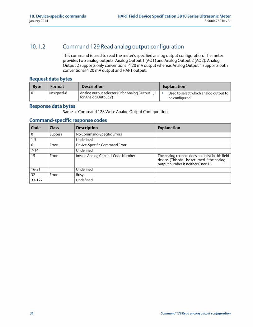
10. Device-specific commands HART Field Device Specification 3810 Series Ultrasonic MeterJanuary 2014 3-9000-762 Rev 3
10.1.2 Command 129 Read analog output configurationThis command is used to read the meter's specified analog output configuration. The meter provides two analog outputs: Analog Output 1 (AO1) and Analog Output 2 (AO2). Analog Output 2 supports only conventional 4 20 mA output whereas Analog Output 1 supports both conventional 4 20 mA output and HART output.
Request data bytes
Response data bytesSame as Command 128 Write Analog Output Configuration.
Command-specific response codes
Byte Format Description Explanation
0 Unsigned-8 Analog output selector (0 for Analog Output 1, 1 for Analog Output 2)
• Used to select which analog output to be configured
Code Class Description Explanation
0 Success No Command-Specific Errors1-5 Undefined6 Error Device-Specific Command Error7-14 Undefined15 Error Invalid Analog Channel Code Number The analog channel does not exist in this field
device. (This shall be returned if the analog output number is neither 0 nor 1.)
16-31 Undefined32 Error Busy33-127 Undefined
34 Command 129 Read analog output configuration
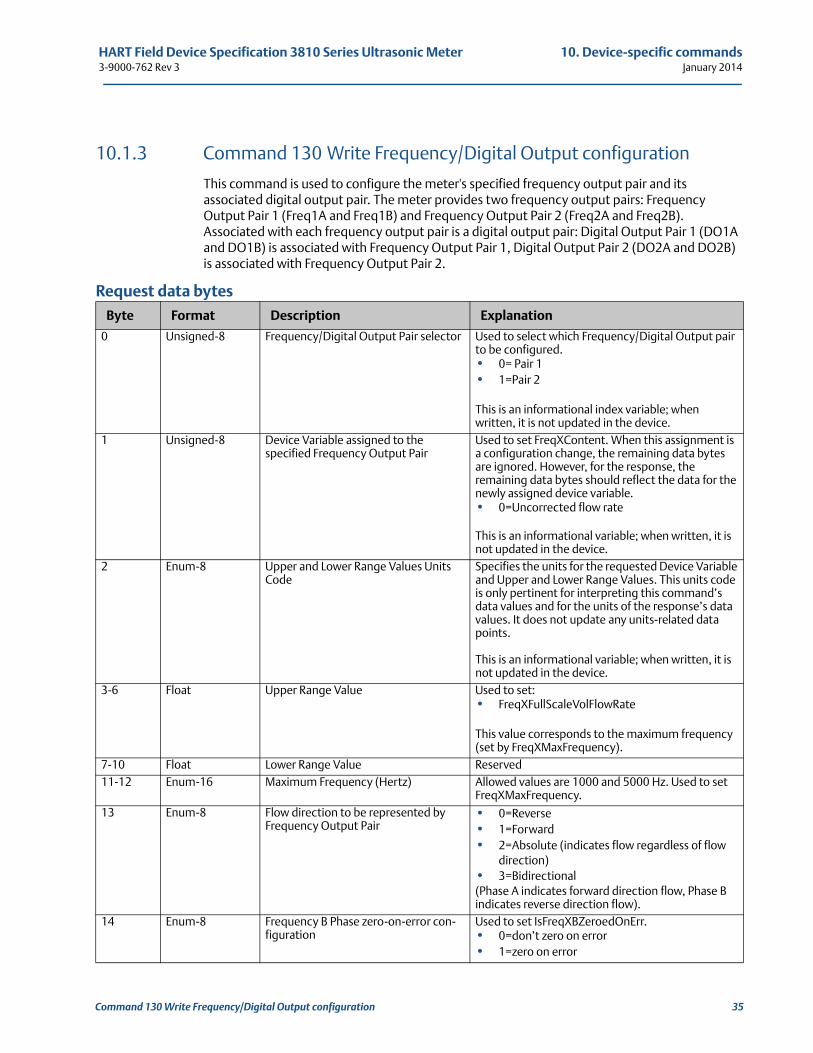
HART Field Device Specification 3810 Series Ultrasonic Meter 10. Device-specific commands3-9000-762 Rev 3 January 2014
10.1.3 Command 130 Write Frequency/Digital Output configuration
This command is used to configure the meter's specified frequency output pair and its associated digital output pair. The meter provides two frequency output pairs: Frequency Output Pair 1 (Freq1A and Freq1B) and Frequency Output Pair 2 (Freq2A and Freq2B). Associated with each frequency output pair is a digital output pair: Digital Output Pair 1 (DO1A and DO1B) is associated with Frequency Output Pair 1, Digital Output Pair 2 (DO2A and DO2B) is associated with Frequency Output Pair 2.
Request data bytes
Byte Format Description Explanation
0 Unsigned-8 Frequency/Digital Output Pair selector Used to select which Frequency/Digital Output pair to be configured.• 0= Pair 1• 1=Pair 2
This is an informational index variable; when written, it is not updated in the device.
1 Unsigned-8 Device Variable assigned to the specified Frequency Output Pair
Used to set FreqXContent. When this assignment is a configuration change, the remaining data bytes are ignored. However, for the response, the remaining data bytes should reflect the data for the newly assigned device variable.• 0=Uncorrected flow rate
This is an informational variable; when written, it is not updated in the device.
2 Enum-8 Upper and Lower Range Values Units Code
Specifies the units for the requested Device Variable and Upper and Lower Range Values. This units code is only pertinent for interpreting this command’s data values and for the units of the response’s data values. It does not update any units-related data points.
This is an informational variable; when written, it is not updated in the device.
3-6 Float Upper Range Value Used to set:• FreqXFullScaleVolFlowRate
This value corresponds to the maximum frequency (set by FreqXMaxFrequency).
7-10 Float Lower Range Value Reserved11-12 Enum-16 Maximum Frequency (Hertz) Allowed values are 1000 and 5000 Hz. Used to set
FreqXMaxFrequency.13 Enum-8 Flow direction to be represented by
Frequency Output Pair• 0=Reverse• 1=Forward• 2=Absolute (indicates flow regardless of flow
direction)• 3=Bidirectional (Phase A indicates forward direction flow, Phase B indicates reverse direction flow).
14 Enum-8 Frequency B Phase zero-on-error con-figuration
Used to set IsFreqXBZeroedOnErr.• 0=don’t zero on error• 1=zero on error
Command 130 Write Frequency/Digital Output configuration 35
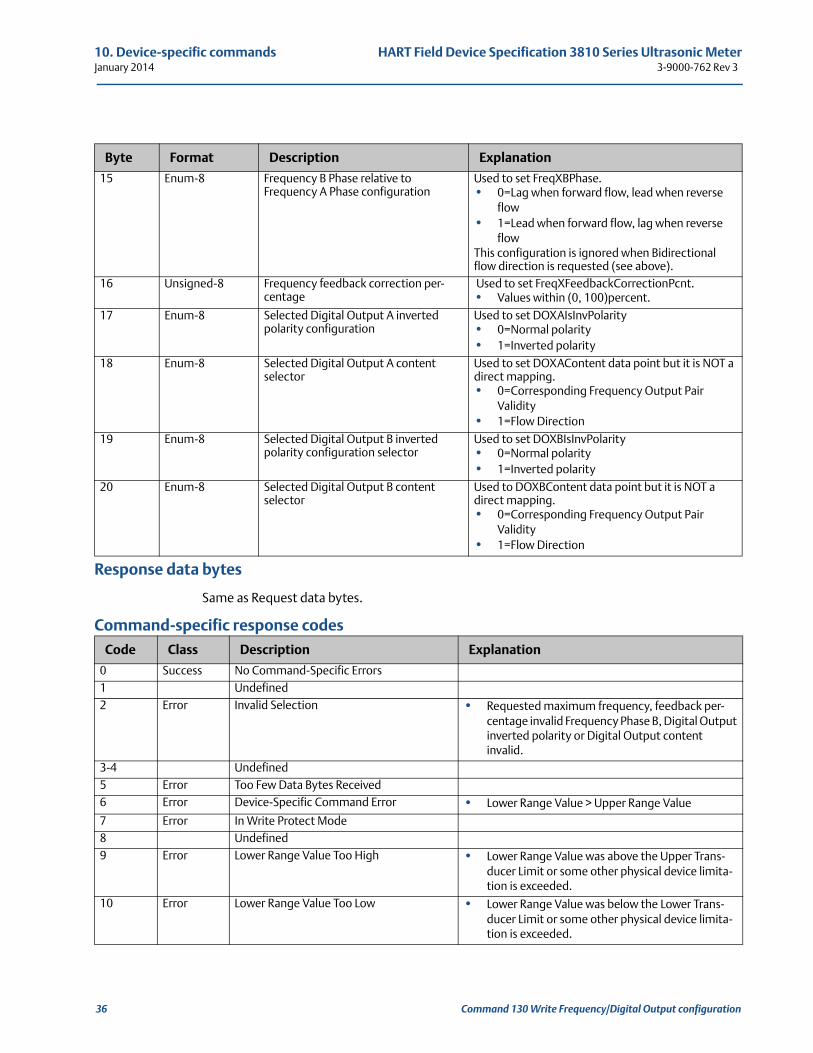
10. Device-specific commands HART Field Device Specification 3810 Series Ultrasonic MeterJanuary 2014 3-9000-762 Rev 3
Response data bytes
Same as Request data bytes.
Command-specific response codes
Byte Format Description Explanation
15 Enum-8 Frequency B Phase relative to Frequency A Phase configuration
Used to set FreqXBPhase.• 0=Lag when forward flow, lead when reverse
flow• 1=Lead when forward flow, lag when reverse
flowThis configuration is ignored when Bidirectional flow direction is requested (see above).
16 Unsigned-8 Frequency feedback correction per-centage
Used to set FreqXFeedbackCorrectionPcnt.• Values within (0, 100)percent.
17 Enum-8 Selected Digital Output A inverted polarity configuration
Used to set DOXAIsInvPolarity• 0=Normal polarity• 1=Inverted polarity
18 Enum-8 Selected Digital Output A content selector
Used to set DOXAContent data point but it is NOT a direct mapping.• 0=Corresponding Frequency Output Pair
Validity• 1=Flow Direction
19 Enum-8 Selected Digital Output B inverted polarity configuration selector
Used to set DOXBIsInvPolarity• 0=Normal polarity• 1=Inverted polarity
20 Enum-8 Selected Digital Output B content selector
Used to DOXBContent data point but it is NOT a direct mapping.• 0=Corresponding Frequency Output Pair
Validity• 1=Flow Direction
Code Class Description Explanation
0 Success No Command-Specific Errors1 Undefined2 Error Invalid Selection • Requested maximum frequency, feedback per-
centage invalid Frequency Phase B, Digital Output inverted polarity or Digital Output content invalid.
3-4 Undefined5 Error Too Few Data Bytes Received6 Error Device-Specific Command Error • Lower Range Value > Upper Range Value
7 Error In Write Protect Mode8 Undefined9 Error Lower Range Value Too High • Lower Range Value was above the Upper Trans-
ducer Limit or some other physical device limita-tion is exceeded.
10 Error Lower Range Value Too Low • Lower Range Value was below the Lower Trans-ducer Limit or some other physical device limita-tion is exceeded.
36 Command 130 Write Frequency/Digital Output configuration
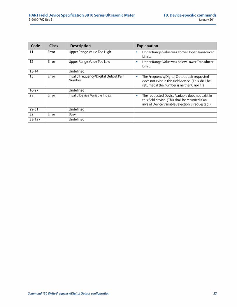
HART Field Device Specification 3810 Series Ultrasonic Meter 10. Device-specific commands3-9000-762 Rev 3 January 2014
11 Error Upper Range Value Too High • Upper Range Value was above Upper Transducer Limit.
12 Error Upper Range Value Too Low • Upper Range Value was below Lower Transducer Limit.
13-14 Undefined15 Error Invalid Frequency/Digital Output Pair
Number• The Frequency/Digital Output pair requested
does not exist in this field device. (This shall be returned if the number is neither 0 nor 1.)
16-27 Undefined28 Error Invalid Device Variable Index • The requested Device Variable does not exist in
this field device. (This shall be returned if an invalid Device Variable selection is requested.)
29-31 Undefined32 Error Busy33-127 Undefined
Code Class Description Explanation
Command 130 Write Frequency/Digital Output configuration 37
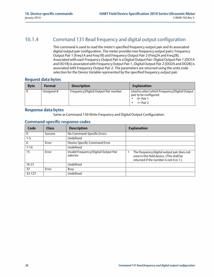
10. Device-specific commands HART Field Device Specification 3810 Series Ultrasonic MeterJanuary 2014 3-9000-762 Rev 3
10.1.4 Command 131 Read frequency and digital output configurationThis command is used to read the meter's specified frequency output pair and its associated digital output pair configuration. The meter provides two frequency output pairs: Frequency Output Pair 1 (Freq1A and Freq1B) and Frequency Output Pair 2 (Freq2A and Freq2B). Associated with each Frequency Output Pair is a Digital Output Pair: Digital Output Pair 1 (DO1A and DO1B) is associated with Frequency Output Pair 1, Digital Output Pair 2 (DO2A and DO2B) is associated with Frequency Output Pair 2. The parameters are returned using the units code selection for the Device Variable represented by the specified frequency output pair.
Request data bytes
Response data bytesSame as Command 130 Write Frequency and Digital Output Configuration.
Command-specific response codes
Byte Format Description Explanation
0 Unsigned-8 Frequency/Digital Output Pair number Used to select which Frequency/Digital Output pair to be configured.• 0= Pair 1• 1= Pair 2
Code Class Description Explanation
0 Success No Command-Specific Errors1-5 Undefined6 Error Device-Specific Command Error7-14 Undefined15 Error Invalid Frequency/Digital Output Pair
selector• The frequency/digital output pair does not
exist in this field device. (This shall be returned if the number is not 0 or 1.)
16-31 Undefined32 Error Busy33-127 Undefined
38 Command 131 Read frequency and digital output configuration
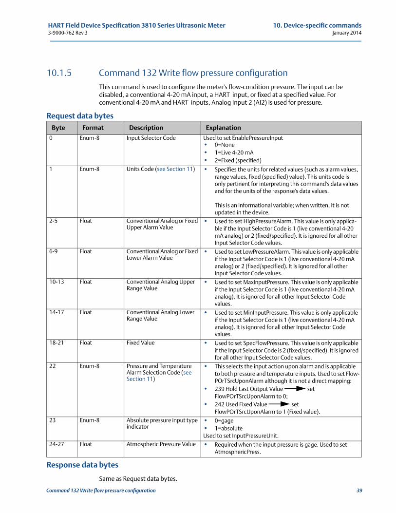
HART Field Device Specification 3810 Series Ultrasonic Meter 10. Device-specific commands3-9000-762 Rev 3 January 2014
Command 132 Write flow pressure configuration 39
10.1.5 Command 132 Write flow pressure configurationThis command is used to configure the meter's flow-condition pressure. The input can be disabled, a conventional 4-20 mA input, a HART input, or fixed at a specified value. For conventional 4-20 mA and HART inputs, Analog Input 2 (AI2) is used for pressure.
Request data bytes
Response data bytes
Same as Request data bytes.
Byte Format Description Explanation
0 Enum-8 Input Selector Code Used to set EnablePressureInput• 0=None• 1=Live 4-20 mA• 2=Fixed (specified)
1 Enum-8 Units Code (see Section 11) • Specifies the units for related values (such as alarm values, range values, fixed (specified) value). This units code is only pertinent for interpreting this command's data values and for the units of the response's data values.
This is an informational variable; when written, it is not updated in the device.
2-5 Float Conventional Analog or Fixed Upper Alarm Value
• Used to set HighPressureAlarm. This value is only applica-ble if the Input Selector Code is 1 (live conventional 4-20 mA analog) or 2 (fixed/specified). It is ignored for all other Input Selector Code values.
6-9 Float Conventional Analog or Fixed Lower Alarm Value
• Used to set LowPressureAlarm. This value is only applicable if the Input Selector Code is 1 (live conventional 4-20 mA analog) or 2 (fixed/specified). It is ignored for all other Input Selector Code values.
10-13 Float Conventional Analog Upper Range Value
• Used to set MaxInputPressure. This value is only applicable if the Input Selector Code is 1 (live conventional 4-20 mA analog). It is ignored for all other Input Selector Code values.
14-17 Float Conventional Analog Lower Range Value
• Used to set MinInputPressure. This value is only applicable if the Input Selector Code is 1 (live conventional 4-20 mA analog). It is ignored for all other Input Selector Code values.
18-21 Float Fixed Value • Used to set SpecFlowPressure. This value is only applicable if the Input Selector Code is 2 (fixed/specified). It is ignored for all other Input Selector Code values.
22 Enum-8 Pressure and Temperature Alarm Selection Code (see Section 11)
• This selects the input action upon alarm and is applicable to both pressure and temperature inputs. Used to set Flow-POrTSrcUponAlarm although it is not a direct mapping:
• 239 Hold Last Output Value set FlowPOrTSrcUponAlarm to 0;
• 242 Used Fixed Value set FlowPOrTSrcUponAlarm to 1 (Fixed value).
23 Enum-8 Absolute pressure input type indicator
• 0=gage• 1=absoluteUsed to set InputPressureUnit.
24-27 Float Atmospheric Pressure Value • Required when the input pressure is gage. Used to set AtmosphericPress.
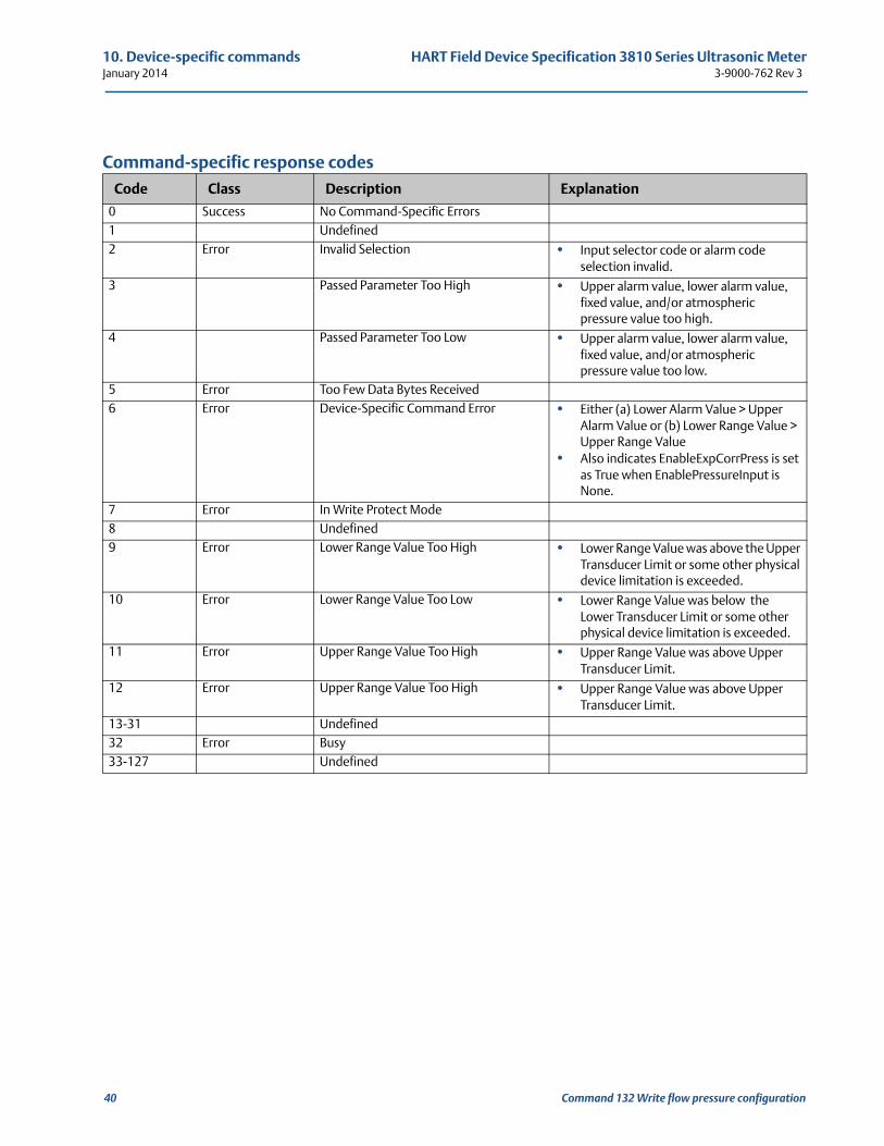
10. Device-specific commands HART Field Device Specification 3810 Series Ultrasonic MeterJanuary 2014 3-9000-762 Rev 3
Command-specific response codes
Code Class Description Explanation
0 Success No Command-Specific Errors1 Undefined2 Error Invalid Selection • Input selector code or alarm code
selection invalid.3 Passed Parameter Too High • Upper alarm value, lower alarm value,
fixed value, and/or atmospheric pressure value too high.
4 Passed Parameter Too Low • Upper alarm value, lower alarm value, fixed value, and/or atmospheric pressure value too low.
5 Error Too Few Data Bytes Received6 Error Device-Specific Command Error • Either (a) Lower Alarm Value > Upper
Alarm Value or (b) Lower Range Value > Upper Range Value
• Also indicates EnableExpCorrPress is set as True when EnablePressureInput is None.
7 Error In Write Protect Mode8 Undefined9 Error Lower Range Value Too High • Lower Range Value was above the Upper
Transducer Limit or some other physical device limitation is exceeded.
10 Error Lower Range Value Too Low • Lower Range Value was below the Lower Transducer Limit or some other physical device limitation is exceeded.
11 Error Upper Range Value Too High • Upper Range Value was above Upper Transducer Limit.
12 Error Upper Range Value Too High • Upper Range Value was above Upper Transducer Limit.
13-31 Undefined32 Error Busy33-127 Undefined
40 Command 132 Write flow pressure configuration
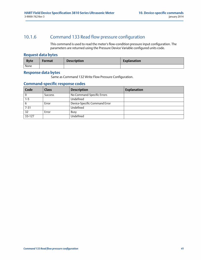
HART Field Device Specification 3810 Series Ultrasonic Meter 10. Device-specific commands3-9000-762 Rev 3 January 2014
10.1.6 Command 133 Read flow pressure configurationThis command is used to read the meter's flow-condition pressure input configuration. The parameters are returned using the Pressure Device Variable configured units code.
Request data bytes
Response data bytes Same as Command 132 Write Flow Pressure Configuration.
Command-specific response codes
Byte Format Description Explanation
None
Code Class Description Explanation
0 Success No Command-Specific Errors1-5 Undefined6 Error Device-Specific Command Error7-31 Undefined32 Error Busy33-127 Undefined
Command 133 Read flow pressure configuration 41
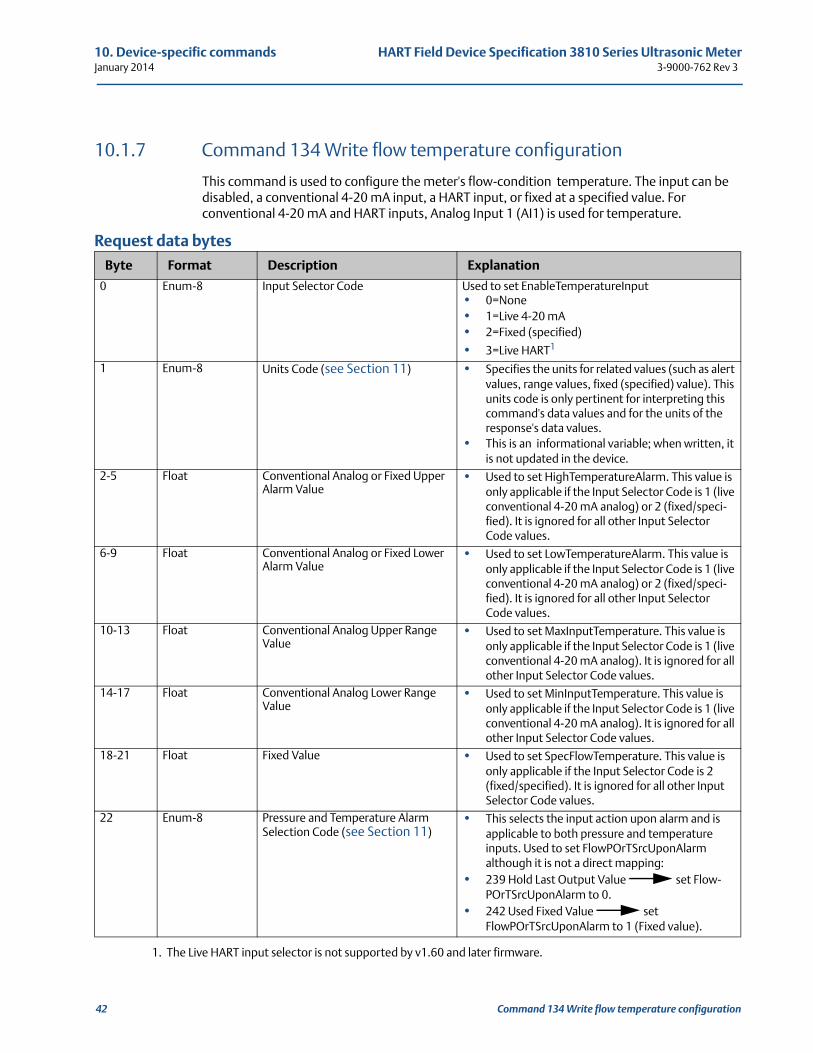
10. Device-specific commands HART Field Device Specification 3810 Series Ultrasonic MeterJanuary 2014 3-9000-762 Rev 3
10.1.7 Command 134 Write flow temperature configuration
This command is used to configure the meter's flow-condition temperature. The input can be disabled, a conventional 4-20 mA input, a HART input, or fixed at a specified value. For conventional 4-20 mA and HART inputs, Analog Input 1 (AI1) is used for temperature.
Request data bytes
Byte Format Description Explanation
0 Enum-8 Input Selector Code Used to set EnableTemperatureInput• 0=None• 1=Live 4-20 mA• 2=Fixed (specified)
• 3=Live HART1
1. The Live HART input selector is not supported by v1.60 and later firmware.
1 Enum-8 Units Code (see Section 11) • Specifies the units for related values (such as alert values, range values, fixed (specified) value). This units code is only pertinent for interpreting this command's data values and for the units of the response's data values.
• This is an informational variable; when written, it is not updated in the device.
2-5 Float Conventional Analog or Fixed Upper Alarm Value
• Used to set HighTemperatureAlarm. This value is only applicable if the Input Selector Code is 1 (live conventional 4-20 mA analog) or 2 (fixed/speci-fied). It is ignored for all other Input Selector Code values.
6-9 Float Conventional Analog or Fixed Lower Alarm Value
• Used to set LowTemperatureAlarm. This value is only applicable if the Input Selector Code is 1 (live conventional 4-20 mA analog) or 2 (fixed/speci-fied). It is ignored for all other Input Selector Code values.
10-13 Float Conventional Analog Upper Range Value
• Used to set MaxInputTemperature. This value is only applicable if the Input Selector Code is 1 (live conventional 4-20 mA analog). It is ignored for all other Input Selector Code values.
14-17 Float Conventional Analog Lower Range Value
• Used to set MinInputTemperature. This value is only applicable if the Input Selector Code is 1 (live conventional 4-20 mA analog). It is ignored for all other Input Selector Code values.
18-21 Float Fixed Value • Used to set SpecFlowTemperature. This value is only applicable if the Input Selector Code is 2 (fixed/specified). It is ignored for all other Input Selector Code values.
22 Enum-8 Pressure and Temperature Alarm Selection Code (see Section 11)
• This selects the input action upon alarm and is applicable to both pressure and temperature inputs. Used to set FlowPOrTSrcUponAlarm although it is not a direct mapping:
• 239 Hold Last Output Value set Flow-POrTSrcUponAlarm to 0.
• 242 Used Fixed Value set FlowPOrTSrcUponAlarm to 1 (Fixed value).
42 Command 134 Write flow temperature configuration
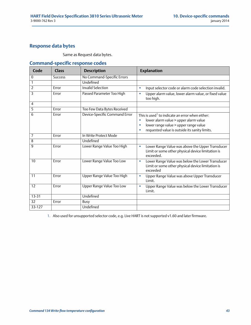
HART Field Device Specification 3810 Series Ultrasonic Meter 10. Device-specific commands3-9000-762 Rev 3 January 2014
Response data bytes
Same as Request data bytes.
Command-specific response codes
Code Class Description Explanation
0 Success No Command-Specific Errors1 Undefined2 Error Invalid Selection • Input selector code or alarm code selection invalid.
3 Error Passed Parameter Too High • Upper alarm value, lower alarm value, or fixed value too high.
45 Error Too Few Data Bytes Received6 Error Device-Specific Command Error This is used1 to indicate an error when either:
• lower alarm value > upper alarm value• lower range value > upper range value • requested value is outside its sanity limits.
1. Also used for unsupported selector code, e.g. Live HART is not supported v1.60 and later firmware.
7 Error In Write Protect Mode8 Undefined9 Error Lower Range Value Too High • Lower Range Value was above the Upper Transducer
Limit or some other physical device limitation is exceeded.
10 Error Lower Range Value Too Low • Lower Range Value was below the Lower Transducer Limit or some other physical device limitation is exceeded
11 Error Upper Range Value Too High • Upper Range Value was above Upper Transducer Limit.
12 Error Upper Range Value Too Low • Upper Range Value was below the Lower Transducer Limit.
13-31 Undefined32 Error Busy33-127 Undefined
Command 134 Write flow temperature configuration 43
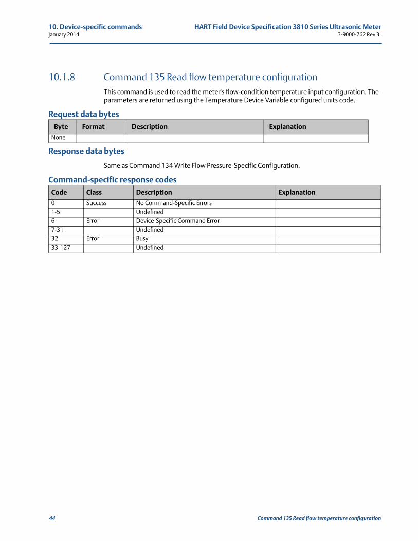
10. Device-specific commands HART Field Device Specification 3810 Series Ultrasonic MeterJanuary 2014 3-9000-762 Rev 3
10.1.8 Command 135 Read flow temperature configurationThis command is used to read the meter's flow-condition temperature input configuration. The parameters are returned using the Temperature Device Variable configured units code.
Request data bytes
Response data bytes
Same as Command 134 Write Flow Pressure-Specific Configuration.
Command-specific response codes
Byte Format Description Explanation
None
Code Class Description Explanation
0 Success No Command-Specific Errors1-5 Undefined6 Error Device-Specific Command Error7-31 Undefined32 Error Busy33-127 Undefined
44 Command 135 Read flow temperature configuration
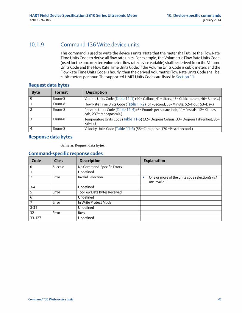
HART Field Device Specification 3810 Series Ultrasonic Meter 10. Device-specific commands3-9000-762 Rev 3 January 2014
10.1.9 Command 136 Write device unitsThis command is used to write the device's units. Note that the meter shall utilize the Flow Rate Time Units Code to derive all flow rate units. For example, the Volumetric Flow Rate Units Code (used for the uncorrected volumetric flow rate device variable) shall be derived from the Volume Units Code and the Flow Rate Time Units Code: if the Volume Units Code is cubic meters and the Flow Rate Time Units Code is hourly, then the derived Volumetric Flow Rate Units Code shall be cubic meters per hour. The supported HART Units Codes are listed in Section 11.
Request data bytes
Response data bytes
Same as Request data bytes.
Command-specific response codes
Byte Format Description
0 Enum-8 Volume Units Code (Table 11-1) (40= Gallons, 41= Liters, 43= Cubic meters, 46= Barrels.)
1 Enum-8 Flow Rate Time Units Code (Table 11-2) (51=Second, 50=Minute, 52=Hour, 53=Day.)
2 Enum-8 Pressure Units Code (Table 11-4) (6= Pounds per square inch, 11= Pascals, 12= Kilopas-cals, 237= Megapascals.)
3 Enum-8 Temperature Units Code (Table 11-5) (32= Degrees Celsius, 33= Degrees Fahrenheit, 35= Kelvin.)
4 Enum-8 Velocity Units Code (Table 11-6) (55= Centipoise, 170 =Pascal second.)
Code Class Description Explanation
0 Success No Command-Specific Errors1 Undefined2 Error Invalid Selection • One or more of the units code selection(s) is/
are invalid.3-4 Undefined5 Error Too Few Data Bytes Received6 Undefined7 Error In Write Protect Mode8-31 Undefined32 Error Busy33-127 Undefined
Command 136 Write device units 45
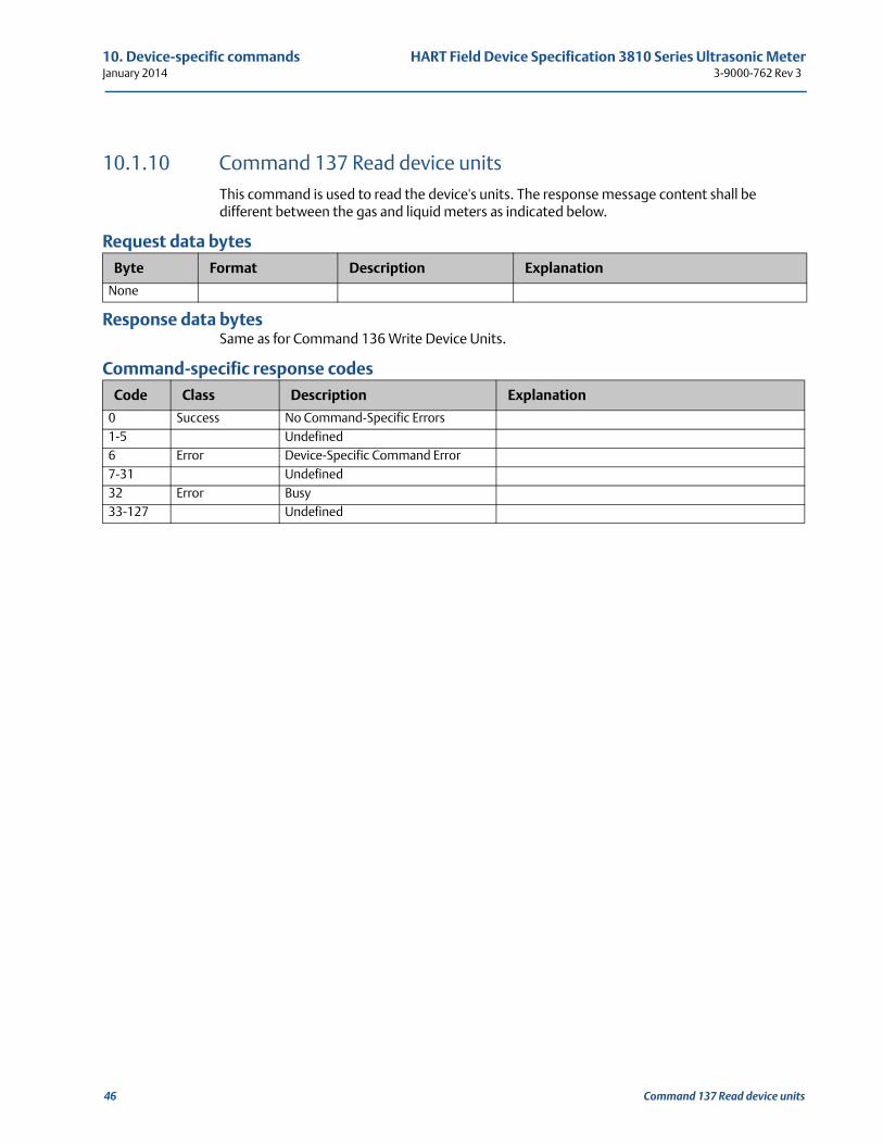
10. Device-specific commands HART Field Device Specification 3810 Series Ultrasonic MeterJanuary 2014 3-9000-762 Rev 3
10.1.10 Command 137 Read device unitsThis command is used to read the device's units. The response message content shall be different between the gas and liquid meters as indicated below.
Request data bytes
Response data bytesSame as for Command 136 Write Device Units.
Command-specific response codes
Byte Format Description Explanation
None
Code Class Description Explanation
0 Success No Command-Specific Errors1-5 Undefined6 Error Device-Specific Command Error7-31 Undefined32 Error Busy33-127 Undefined
46 Command 137 Read device units
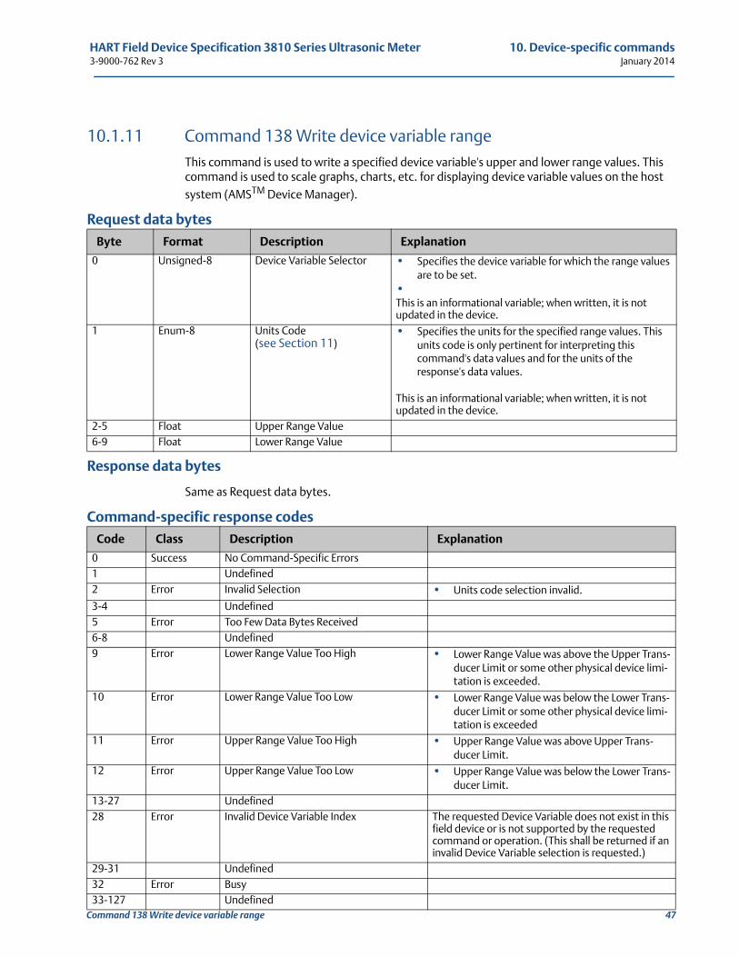
HART Field Device Specification 3810 Series Ultrasonic Meter 10. Device-specific commands3-9000-762 Rev 3 January 2014
Command 138 Write device variable range 47
10.1.11 Command 138 Write device variable rangeThis command is used to write a specified device variable's upper and lower range values. This command is used to scale graphs, charts, etc. for displaying device variable values on the host
system (AMSTM Device Manager).
Request data bytes
Response data bytes
Same as Request data bytes.
Command-specific response codes
Byte Format Description Explanation
0 Unsigned-8 Device Variable Selector • Specifies the device variable for which the range values are to be set.
•This is an informational variable; when written, it is not updated in the device.
1 Enum-8 Units Code (see Section 11)
• Specifies the units for the specified range values. This units code is only pertinent for interpreting this command's data values and for the units of the response's data values.
This is an informational variable; when written, it is not updated in the device.
2-5 Float Upper Range Value6-9 Float Lower Range Value
Code Class Description Explanation
0 Success No Command-Specific Errors1 Undefined2 Error Invalid Selection • Units code selection invalid.
3-4 Undefined5 Error Too Few Data Bytes Received6-8 Undefined9 Error Lower Range Value Too High • Lower Range Value was above the Upper Trans-
ducer Limit or some other physical device limi-tation is exceeded.
10 Error Lower Range Value Too Low • Lower Range Value was below the Lower Trans-ducer Limit or some other physical device limi-tation is exceeded
11 Error Upper Range Value Too High • Upper Range Value was above Upper Trans-ducer Limit.
12 Error Upper Range Value Too Low • Upper Range Value was below the Lower Trans-ducer Limit.
13-27 Undefined28 Error Invalid Device Variable Index The requested Device Variable does not exist in this
field device or is not supported by the requested command or operation. (This shall be returned if an invalid Device Variable selection is requested.)
29-31 Undefined32 Error Busy33-127 Undefined
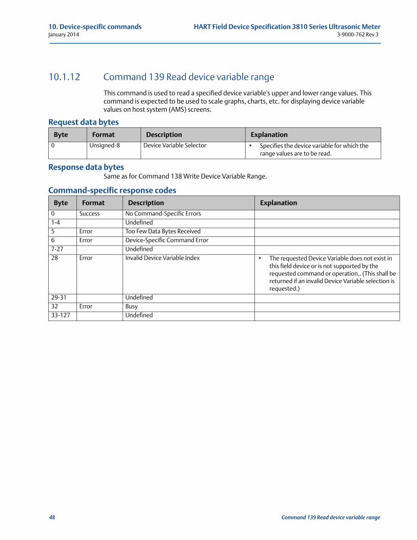
10. Device-specific commands HART Field Device Specification 3810 Series Ultrasonic MeterJanuary 2014 3-9000-762 Rev 3
in
be is
10.1.12 Command 139 Read device variable range
This command is used to read a specified device variable's upper and lower range values. This command is expected to be used to scale graphs, charts, etc. for displaying device variable values on host system (AMS) screens.
Request data bytes
Response data bytesSame as for Command 138 Write Device Variable Range.
Command-specific response codes
Byte Format Description Explanation
0 Unsigned-8 Device Variable Selector • Specifies the device variable for which the range values are to be read.
Byte Format Description Explanation
0 Success No Command-Specific Errors1-4 Undefined5 Error Too Few Data Bytes Received6 Error Device-Specific Command Error7-27 Undefined28 Error Invalid Device Variable Index • The requested Device Variable does not exist
this field device or is not supported by the requested command or operation.. (This shallreturned if an invalid Device Variable selectionrequested.)
29-31 Undefined32 Error Busy33-127 Undefined
48 Command 139 Read device variable range
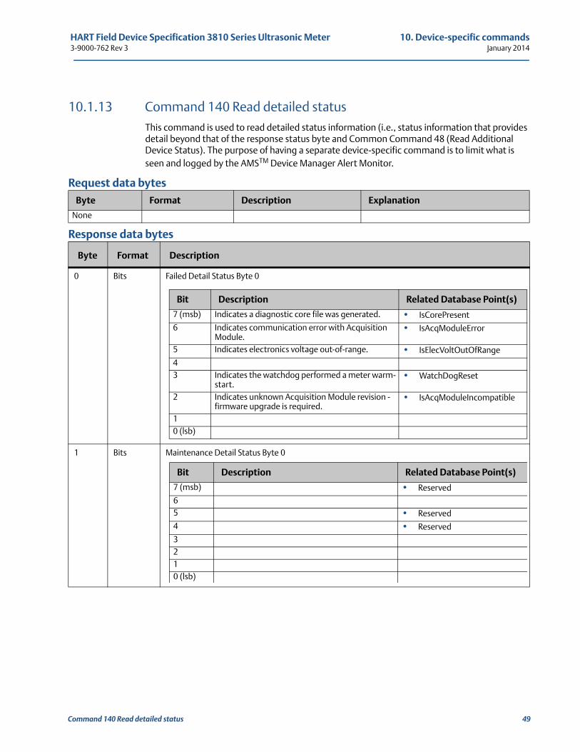
HART Field Device Specification 3810 Series Ultrasonic Meter 10. Device-specific commands3-9000-762 Rev 3 January 2014
10.1.13 Command 140 Read detailed statusThis command is used to read detailed status information (i.e., status information that provides detail beyond that of the response status byte and Common Command 48 (Read Additional Device Status). The purpose of having a separate device-specific command is to limit what is seen and logged by the AMSTM Device Manager Alert Monitor.
Request data bytes
Response data bytes
Byte Format Description Explanation
None
Byte Format Description
0 Bits Failed Detail Status Byte 0
1 Bits Maintenance Detail Status Byte 0
Bit Description Related Database Point(s)
7 (msb) Indicates a diagnostic core file was generated. • IsCorePresent
6 Indicates communication error with Acquisition Module.
• IsAcqModuleError
5 Indicates electronics voltage out-of-range. • IsElecVoltOutOfRange
43 Indicates the watchdog performed a meter warm-
start.• WatchDogReset
2 Indicates unknown Acquisition Module revision - firmware upgrade is required.
• IsAcqModuleIncompatible
10 (lsb)
Bit Description Related Database Point(s)
7 (msb) • Reserved
65 • Reserved
4 • Reserved
3210 (lsb)
Command 140 Read detailed status 49
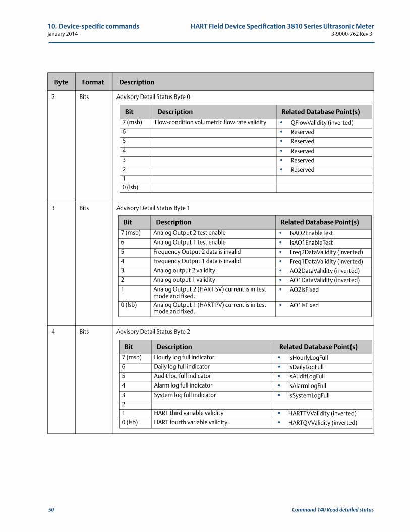
10. Device-specific commands HART Field Device Specification 3810 Series Ultrasonic MeterJanuary 2014 3-9000-762 Rev 3
2 Bits Advisory Detail Status Byte 0
3 Bits Advisory Detail Status Byte 1
4 Bits Advisory Detail Status Byte 2
Byte Format Description
Bit Description Related Database Point(s)
7 (msb) Flow-condition volumetric flow rate validity • QFlowValidity (inverted)
6 • Reserved
5 • Reserved
4 • Reserved
3 • Reserved
2 • Reserved
10 (lsb)
Bit Description Related Database Point(s)
7 (msb) Analog Output 2 test enable • IsAO2EnableTest
6 Analog Output 1 test enable • IsAO1EnableTest
5 Frequency Output 2 data is invalid • Freq2DataValidity (inverted)
4 Frequency Output 1 data is invalid • Freq1DataValidity (inverted)
3 Analog output 2 validity • AO2DataValidity (inverted)
2 Analog output 1 validity • AO1DataValidity (inverted)
1 Analog Output 2 (HART SV) current is in test mode and fixed.
• AO2IsFixed
0 (lsb) Analog Output 1 (HART PV) current is in test mode and fixed.
• AO1IsFixed
Bit Description Related Database Point(s)
7 (msb) Hourly log full indicator • IsHourlyLogFull
6 Daily log full indicator • IsDailyLogFull
5 Audit log full indicator • IsAuditLogFull
4 Alarm log full indicator • IsAlarmLogFull
3 System log full indicator • IsSystemLogFull
21 HART third variable validity • HARTTVValidity (inverted)
0 (lsb) HART fourth variable validity • HARTQVValidity (inverted)
50 Command 140 Read detailed status
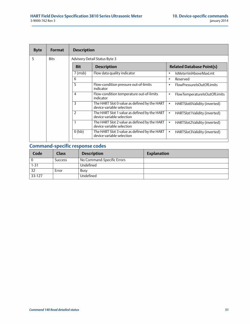
HART Field Device Specification 3810 Series Ultrasonic Meter 10. Device-specific commands3-9000-762 Rev 3 January 2014
Command-specific response codes
5 Bits Advisory Detail Status Byte 3
Code Class Description Explanation
0 Success No Command-Specific Errors1-31 Undefined32 Error Busy33-127 Undefined
Byte Format Description
Bit Description Related Database Point(s)
7 (msb) Flow data quality indicator • IsMeterVelAboveMaxLmt
6 • Reserved
5 Flow-condition pressure out-of-limits indicator
• FlowPressureIsOutOfLimits
4 Flow-condition temperature out-of-limits indicator
• FlowTemperatureIsOutOfLimits
3 The HART Slot 0 value as defined by the HART device variable selection
• HARTSlot0Validity (inverted)
2 The HART Slot 1 value as defined by the HART device variable selection
• HARTSlot1Validity (inverted)
1 The HART Slot 2 value as defined by the HART device variable selection
• HARTSlot2Validity (inverted)
0 (lsb) The HART Slot 3 value as defined by the HART device variable selection
• HARTSlot3Validity (inverted)
Command 140 Read detailed status 51
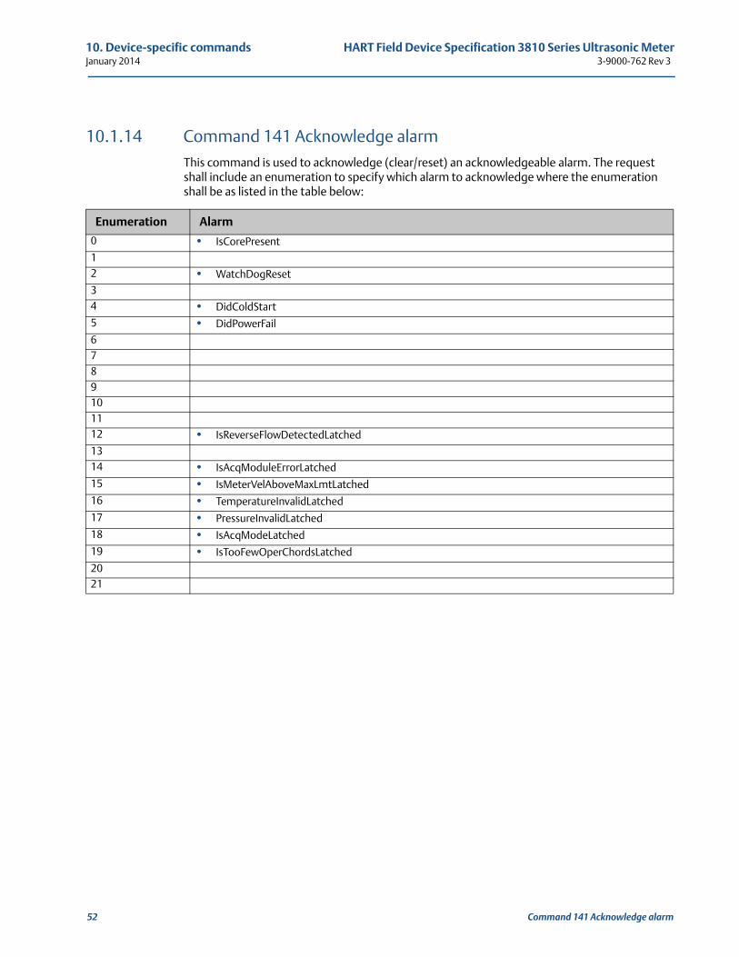
10. Device-specific commands HART Field Device Specification 3810 Series Ultrasonic MeterJanuary 2014 3-9000-762 Rev 3
10.1.14 Command 141 Acknowledge alarmThis command is used to acknowledge (clear/reset) an acknowledgeable alarm. The request shall include an enumeration to specify which alarm to acknowledge where the enumeration shall be as listed in the table below:
Enumeration Alarm
0 • IsCorePresent
12 • WatchDogReset
34 • DidColdStart
5 • DidPowerFail
6789101112 • IsReverseFlowDetectedLatched
1314 • IsAcqModuleErrorLatched
15 • IsMeterVelAboveMaxLmtLatched
16 • TemperatureInvalidLatched
17 • PressureInvalidLatched
18 • IsAcqModeLatched
19 • IsTooFewOperChordsLatched
2021
52 Command 141 Acknowledge alarm
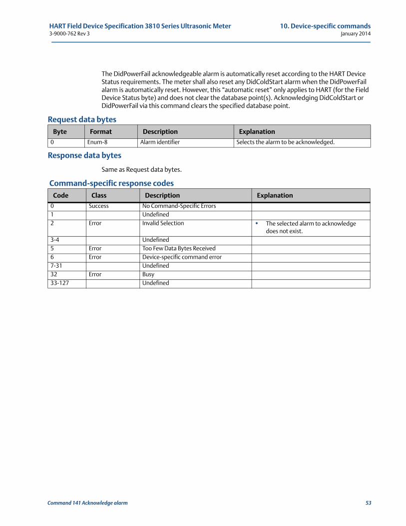
HART Field Device Specification 3810 Series Ultrasonic Meter 10. Device-specific commands3-9000-762 Rev 3 January 2014
The DidPowerFail acknowledgeable alarm is automatically reset according to the HART Device Status requirements. The meter shall also reset any DidColdStart alarm when the DidPowerFail alarm is automatically reset. However, this “automatic reset” only applies to HART (for the Field Device Status byte) and does not clear the database point(s). Acknowledging DidColdStart or DidPowerFail via this command clears the specified database point.
Request data bytes
Response data bytes
Same as Request data bytes.
Command-specific response codes
Byte Format Description Explanation
0 Enum-8 Alarm identifier Selects the alarm to be acknowledged.
Code Class Description Explanation
0 Success No Command-Specific Errors1 Undefined2 Error Invalid Selection • The selected alarm to acknowledge
does not exist.3-4 Undefined5 Error Too Few Data Bytes Received6 Error Device-specific command error7-31 Undefined32 Error Busy33-127 Undefined
Command 141 Acknowledge alarm 53
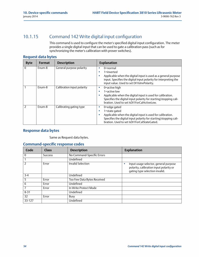
10. Device-specific commands HART Field Device Specification 3810 Series Ultrasonic MeterJanuary 2014 3-9000-762 Rev 3
10.1.15 Command 142 Write digital input configurationThis command is used to configure the meter's specified digital input configuration. The meter provides a single digital input that can be used to gate a calibration pass (such as for synchronizing the meter's calibration with prover switches).
Request data bytes
Response data bytes
Same as Request data bytes.
Command-specific response codes
Byte Format Description Explanation
0 Enum-8 General purpose polarity • 0=normal• 1=inverted• Applicable when the digital input is used as a general purpose
input. Specifies the digital input polarity for interpreting the input value. Used to set DI1IsInvPolarity.
1 Enum-8 Calibration input polarity • 0=active high• 1=active low• Applicable when the digital input is used for calibration.
Specifies the digital input polarity for starting/stopping cali-bration. Used to set IsDI1ForCalActiveLow.
2 Enum-8 Calibrating gating type • 0=edge gated• 1=state gated• Applicable when the digital input is used for calibration.
Specifies the digital input polarity for starting/stopping cali-bration. Used to set IsDI1ForCalStateGated.
Code Class Description Explanation
0 Success No Command-Specific Errors1 Undefined2 Error Invalid Selection • Input usage selector, general purpose
polarity, calibration input polarity or gating type selection invalid.
3-4 Undefined5 Error Too Few Data Bytes Received6 Error Undefined7 Error In Write Protect Mode8-31 Undefined32 Error Busy33-127 Undefined
54 Command 142 Write digital input configuration
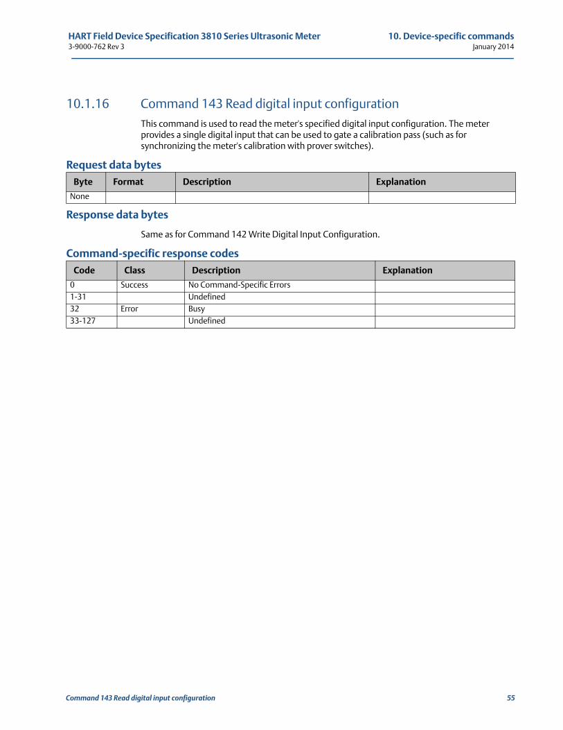
HART Field Device Specification 3810 Series Ultrasonic Meter 10. Device-specific commands3-9000-762 Rev 3 January 2014
10.1.16 Command 143 Read digital input configurationThis command is used to read the meter's specified digital input configuration. The meter provides a single digital input that can be used to gate a calibration pass (such as for synchronizing the meter's calibration with prover switches).
Request data bytes
Response data bytes
Same as for Command 142 Write Digital Input Configuration.
Command-specific response codes
Byte Format Description Explanation
None
Code Class Description Explanation
0 Success No Command-Specific Errors1-31 Undefined32 Error Busy33-127 Undefined
Command 143 Read digital input configuration 55
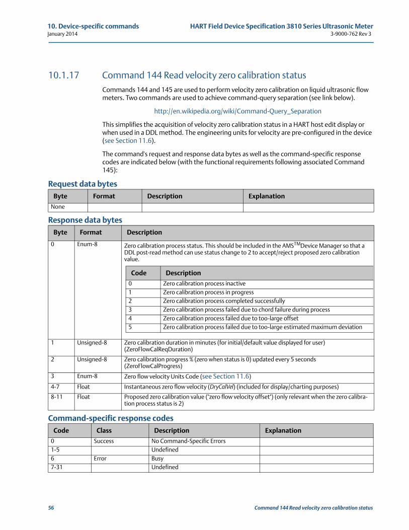
10. Device-specific commands HART Field Device Specification 3810 Series Ultrasonic MeterJanuary 2014 3-9000-762 Rev 3
10.1.17 Command 144 Read velocity zero calibration statusCommands 144 and 145 are used to perform velocity zero calibration on liquid ultrasonic flow meters. Two commands are used to achieve command-query separation (see link below).
http://en.wikipedia.org/wiki/Command-Query_Separation
This simplifies the acquisition of velocity zero calibration status in a HART host edit display or when used in a DDL method. The engineering units for velocity are pre-configured in the device (see Section 11.6).
The command's request and response data bytes as well as the command-specific response codes are indicated below (with the functional requirements following associated Command 145):
Request data bytes
Response data bytes
Command-specific response codes
Byte Format Description Explanation
None
Byte Format Description
0 Enum-8 Zero calibration process status. This should be included in the AMSTMDevice Manager so that a DDL post-read method can use status change to 2 to accept/reject proposed zero calibration value.
1 Unsigned-8 Zero calibration duration in minutes (for initial/default value displayed for user) (ZeroFlowCalReqDuration)
2 Unsigned-8 Zero calibration progress % (zero when status is 0) updated every 5 seconds (ZeroFlowCalProgress)
3 Enum-8 Zero flow velocity Units Code (see Section 11.6)
4-7 Float Instantaneous zero flow velocity (DryCalVel) (included for display/charting purposes)
8-11 Float Proposed zero calibration value ("zero flow velocity offset") (only relevant when the zero calibra-tion process status is 2)
Code Class Description Explanation
0 Success No Command-Specific Errors1-5 Undefined6 Error Busy7-31 Undefined
Code Description
0 Zero calibration process inactive1 Zero calibration process in progress2 Zero calibration process completed successfully3 Zero calibration process failed due to chord failure during process4 Zero calibration process failed due to too-large offset5 Zero calibration process failed due to too-large estimated maximum deviation
56 Command 144 Read velocity zero calibration status
HART Field Device Specification 3810 Series Ultrasonic Meter 10. Device-specific commands3-9000-762 Rev 3 January 2014
32 Error33-127 Undefined
Code Class Description Explanation
Command 144 Read velocity zero calibration status 57
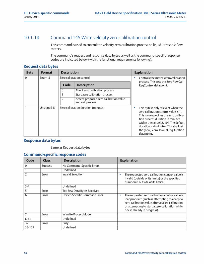
10. Device-specific commands HART Field Device Specification 3810 Series Ultrasonic MeterJanuary 2014 3-9000-762 Rev 3
10.1.18 Command 145 Write velocity zero calibration controlThis command is used to control the velocity zero calibration process on liquid ultrasonic flow meters.
The command's request and response data bytes as well as the command-specific response codes are indicated below (with the functional requirements following):
Request data bytes
Response data bytes
Same as Request data bytes
Command-specific response codes
Byte Format Description Explanation
0 Enum-8 Zero calibration control • Controls the meter's zero calibration process. This sets the ZeroFlowCal-ReqControl data point.
1 Unsigned-8 Zero calibration duration (minutes) • This byte is only relevant when the zero calibration control value is 1. This value specifies the zero calibra-tion process duration in minutes within the range [2, 10]. The default duration is 4 minutes. This shall set the (new) ZeroFlowCalReqDuration data point.
Code Class Description Explanation
0 Success No Command-Specific Errors1 Undefined2 Error Invalid Selection • The requested zero calibration control value is
invalid (outside of its limits) or the specified duration is outside of its limits.
3-4 Undefined5 Error Too Few Data Bytes Received6 Error Device-Specific Command Error • The requested zero calibration control value is
inappropriate (such as attempting to accept a zero calibration value after a failed calibration or attempting to start a zero calibration while one is already in progress).
7 Error In Write Protect Mode8-31 Undefined32 Error Busy33-127 Undefined
Code Description
0 Abort zero calibration process1 Start zero calibration process2 Accept proposed zero calibration value
and exit process
58 Command 145 Write velocity zero calibration control
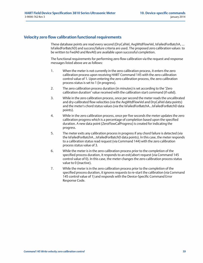
HART Field Device Specification 3810 Series Ultrasonic Meter 10. Device-specific commands3-9000-762 Rev 3 January 2014
Velocity zero flow calibration functional requirements
These database points are read every second (DryCalVel, AvgWtdFlowVel, IsFailedForBatchA, … IsFailedForBatchD) and success/failure criteria are used. The proposed zero calibration values to be written to FwdA0 and RevA0) are available upon successful completion.
The functional requirements for performing zero flow calibration via the request and response messages listed above are as follows:
1. When the meter is not currently in the zero calibration process, it enters the zero calibration process upon receiving HART Command 145 with the zero calibration control value of 1. Upon entering the zero calibration process, the zero calibration process status is set to 1 (in progress).
2. The zero calibration process duration (in minutes) is set according to the "Zero calibration duration" value received with the calibration start command (if valid).
3. While in the zero calibration process, once per second the meter reads the uncalibrated and dry-calibrated flow velocities (via the AvgWtdFlowVel and DryCalVel data points) and the meter's chord status values (via the IsFailedForBatchA…IsFailedForBatchD data points).
4. While in the zero calibration process, once per five seconds the meter updates the zero calibration progress which is a percentage of completion based upon the specified duration. A new data point (ZeroFlowCalProgress) is created for indicating the progress.
5. The meter exits any calibration process in progress if any chord failure is detected (via the IsFailedForBatchA…IsFailedForBatchD data points). In this case, the meter responds to a calibration status read request (via Command 144) with the zero calibration process status value of 3.
6. While the meter is in the zero calibration process prior to the completion of the specified process duration, it responds to an exit/abort request (via Command 145 control value of 0). In this case, the meter changes the zero calibration process status value to 0 (inactive).
7. While the meter is in the zero calibration process prior to the completion of the specified process duration, it ignores requests to re-start the calibration (via Command 145 control value of 1) and responds with the Device-Specific Command Error Response Code.
Command 145 Write velocity zero calibration control 59
10. Device-specific commands HART Field Device Specification 3810 Series Ultrasonic MeterJanuary 2014 3-9000-762 Rev 3
8. While the meter is in the zero calibration process prior to the completion of the specified process duration, it responds to all calibration status read requests (via Command 144) with the zero calibration process status value of 1 (zero calibration in progress).
9. While the meter is in the zero calibration process prior to the completion of the specified process duration, it ignores requests to accept the proposed zero calibration value (via Command 145 control value of 2) and responds with the Device-Specific Command Error Response Code.
10. When the zero calibration process reaches the specified process duration, then the meter determines whether the calibration was successful or not as follows:
(a) If the absolute value of the proposed zero calibration value (calculated as shown below) is greater than 0.02 ft/sec, then the zero calibration failed. In this case, the meter responds to the next calibration process status read request (via Command 144) with a zero calibration process status value of 4.
The proposed zero calibration value is calculated as follows:
where
is the average of the average weighted flow velocity values (ft/sec)
(b) If the dry-calibrated flow velocity Estimated Maximum Deviation (calculated as shown below) is greater than 0.002 ft/sec, then the zero calibration failed. In this case, the meter responds to the next calibration process status read request (via Command 144) with a zero calibration process status value of 5.
ZeroCalibrationValue AvgWtdFlowVel–=
AvgWtdFlowVel
60 Command 145 Write velocity zero calibration control
HART Field Device Specification 3810 Series Ultrasonic Meter 10. Device-specific commands3-9000-762 Rev 3 January 2014
The dry-calibrated flow velocity Estimated Maximum Deviation is calculated as follows:
where:
is the dry-calibrated flow velocity standard deviation during the process (ft/
sec)
N is the number of dry-calibrated flow velocity values taken during the process
(c) Otherwise, the zero calibration completed successfully and the meter responds to the next calibration process status read request (via Command 144) with a zero calibration process status value of 2 and the proposed zero calibration value (in the HART-configured velocity units).
11. When a zero calibration process ends unsuccessfully (i.e., with a status value of 3, 4, or 5), the meter ignores requests to accept the proposed zero calibration value (via Command 145 control value of 2). In this case, the meter responds with the Device-Specific Command Error Response Code.
12. When a zero calibration process ends unsuccessfully (i.e., with a status value of 3, 4, or 5), the meter continues to respond to zero calibration process status read requests (via Command 144) with the same status response until the calibration is exited/aborted (via Command 145 control value of 0) or re-started (via Command 145 control value of 1).
(a) In this case, the meter responds to the exit/abort command by setting the status value to 0 (inactive).
(b) In this case, the meter responds to the start command by setting the status value to 1 (in progress).
13. When the zero calibration process ends successfully, the meter continues to respond to zero calibration process status read requests (via Command 144) with the successful completion response (status value of 2) until any other following occurs:
(a) The proposed zero calibration value is accepted (via Command 145 control value of 2) - in this case the meter writes the proposed zero calibration value to the FwdA0 and RevA0 data points and set the status value to 0 (inactive).
(b) The proposed zero calibration value is rejected via exiting the process (via Command 145 control value of 0) - the meter discards the proposed zero calibration value and set the status value to 0 (in active).
(c) The proposed zero calibration value is rejected via re-starting the process (via Command 145 control value of 1) - the meter discards the proposed zero calibration value and re-start the process. In this case, the meter sets the status value to 1 (in progress).
14. When the meter is not in the zero calibration process, it responds to requests to exit/abort (via Command 145 control value of 0) with the Device-Specific Command Error Response Code.
15. When the meter is not in the zero calibration process, it responds to requests to accept the proposed zero calibration value (via Command 145 control value of 2) with the Device-Specific Command Error Response Code.
EstimatedMaximumDeviationDryCalVel 3δDryCalVel
N------------------------------×=
δDryCalVel
Command 145 Write velocity zero calibration control 61
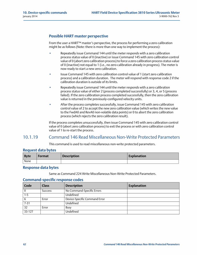
10. Device-specific commands HART Field Device Specification 3810 Series Ultrasonic MeterJanuary 2014 3-9000-762 Rev 3
Possible HART master perspective
From the user a HART™ master’s perspective, the process for performing a zero calibration might be as follows (Note: there is more than one way to implement the process):
• Repeatedly issue Command 144 until the meter responds with a zero calibration process status value of 0 (inactive) or issue Command 145 with zero calibration control value of 0 (abort zero calibration process) to force a zero calibration process status value of 0 (inactive) not equal to 1 (i.e., no zero calibration already in progress). The meter is now ready to start a new zero calibration.
• Issue Command 145 with zero calibration control value of 1 (start zero calibration process) and a calibration duration. The meter will respond with response code 2 if the calibration duration is outside of its limits.
• Repeatedly issue Command 144 until the meter responds with a zero calibration process status value of either 2 (process completed successfully) or 3, 4, or 5 (process failed). If the zero calibration process completed successfully, then the zero calibration value is returned in the previously-configured velocity units.
• After the process completes successfully, issue Command 145 with zero calibration control value of 2 to accept the new zero calibration value (which writes the new value to the FwdA0 and RevA0 non-volatile data points) or 0 to abort the zero calibration process (which rejects the zero calibration result).
If the process completes unsuccessfully, then issue Command 145 with zero calibration control value of 0 (abort zero calibration process) to exit the process or with zero calibration control value of 1 to re-start the process.
10.1.19 Command 146 Read Miscellaneous Non-Write Protected ParametersThis command is used to read miscellaneous non-write protected parameters.
Request data bytes
Response data bytes
Same as Command 224 Write Miscellaneous Non-Write Protected Parameters.
Command-specific response codes
Byte Format Description Explanation
None
Code Class Description Explanation
0 Success No Command-Specific Errors1-5 Undefined6 Error Device-Specific Command Error7-31 Undefined32 Error Busy33-127 Undefined
62 Command 146 Read Miscellaneous Non-Write Protected Parameters
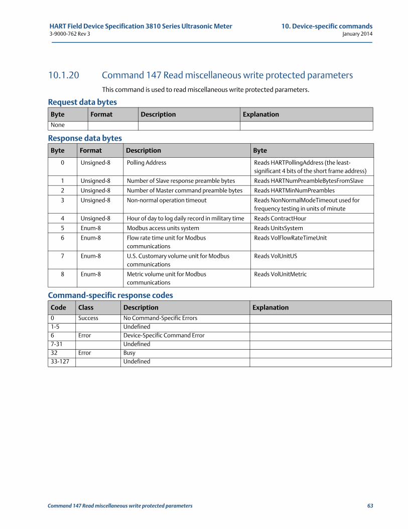
HART Field Device Specification 3810 Series Ultrasonic Meter 10. Device-specific commands3-9000-762 Rev 3 January 2014
10.1.20 Command 147 Read miscellaneous write protected parametersThis command is used to read miscellaneous write protected parameters.
Request data bytes
Response data bytes
Command-specific response codes
Byte Format Description Explanation
None
Byte Format Description Byte
0 Unsigned-8 Polling Address Reads HARTPollingAddress (the least-significant 4 bits of the short frame address)
1 Unsigned-8 Number of Slave response preamble bytes Reads HARTNumPreambleBytesFromSlave
2 Unsigned-8 Number of Master command preamble bytes Reads HARTMinNumPreambles
3 Unsigned-8 Non-normal operation timeout Reads NonNormalModeTimeout used for frequency testing in units of minute
4 Unsigned-8 Hour of day to log daily record in military time Reads ContractHour
5 Enum-8 Modbus access units system Reads UnitsSystem
6 Enum-8 Flow rate time unit for Modbus communications
Reads VolFlowRateTimeUnit
7 Enum-8 U.S. Customary volume unit for Modbus communications
Reads VolUnitUS
8 Enum-8 Metric volume unit for Modbus communications
Reads VolUnitMetric
Code Class Description Explanation
0 Success No Command-Specific Errors1-5 Undefined6 Error Device-Specific Command Error7-31 Undefined32 Error Busy33-127 Undefined
Command 147 Read miscellaneous write protected parameters 63
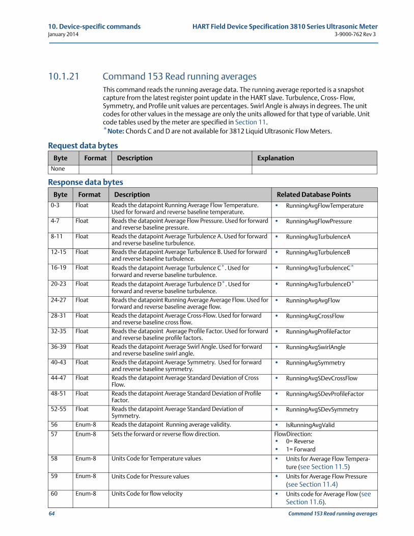
10. Device-specific commands HART Field Device Specification 3810 Series Ultrasonic MeterJanuary 2014 3-9000-762 Rev 3
64 Command 153 Read running averages
10.1.21 Command 153 Read running averagesThis command reads the running average data. The running average reported is a snapshot capture from the latest register point update in the HART slave. Turbulence, Cross- Flow, Symmetry, and Profile unit values are percentages. Swirl Angle is always in degrees. The unit codes for other values in the message are only the units allowed for that type of variable. Unit code tables used by the meter are specified in Section 11. *Note: Chords C and D are not available for 3812 Liquid Ultrasonic Flow Meters.
Request data bytes
Response data bytes
Byte Format Description Explanation
None
Byte Format Description Related Database Points
0-3 Float Reads the datapoint Running Average Flow Temperature. Used for forward and reverse baseline temperature.
• RunningAvgFlowTemperature
4-7 Float Reads the datapoint Average Flow Pressure. Used for forward and reverse baseline pressure.
• RunningAvgFlowPressure
8-11 Float Reads the datapoint Average Turbulence A. Used for forward and reverse baseline turbulence.
• RunningAvgTurbulenceA
12-15 Float Reads the datapoint Average Turbulence B. Used for forward and reverse baseline turbulence.
• RunningAvgTurbulenceB
16-19 Float Reads the datapoint Average Turbulence C*. Used for forward and reverse baseline turbulence.
• RunningAvgTurbulenceC*
20-23 Float Reads the datapoint Average Turbulence D*. Used for forward and reverse baseline turbulence.
• RunningAvgTurbulenceD*
24-27 Float Reads the datapoint Running Average Average Flow. Used for forward and reverse baseline average flow.
• RunningAvgAvgFlow
28-31 Float Reads the datapoint Average Cross-Flow. Used for forward and reverse baseline cross flow.
• RunningAvgCrossFlow
32-35 Float Reads the datapoint Average Profile Factor. Used for forward and reverse baseline profile factors.
• RunningAvgProfileFactor
36-39 Float Reads the datapoint Average Swirl Angle. Used for forward and reverse baseline swirl angle.
• RunningAvgSwirlAngle
40-43 Float Reads the datapoint Average Symmetry. Used for forward and reverse baseline symmetry.
• RunningAvgSymmetry
44-47 Float Reads the datapoint Average Standard Deviation of Cross Flow.
• RunningAvgSDevCrossFlow
48-51 Float Reads the datapoint Average Standard Deviation of Profile Factor.
• RunningAvgSDevProfileFactor
52-55 Float Reads the datapoint Average Standard Deviation of Symmetry.
• RunningAvgSDevSymmetry
56 Enum-8 Reads the datapoint Running average validity. • IsRunningAvgValid
57 Enum-8 Sets the forward or reverse flow direction. FlowDirection:• 0= Reverse• 1= Forward
58 Enum-8 Units Code for Temperature values • Units for Average Flow Tempera-ture (see Section 11.5)
59 Enum-8 Units Code for Pressure values • Units for Average Flow Pressure (see Section 11.4)
60 Enum-8 Units Code for flow velocity • Units code for Average Flow (see Section 11.6).
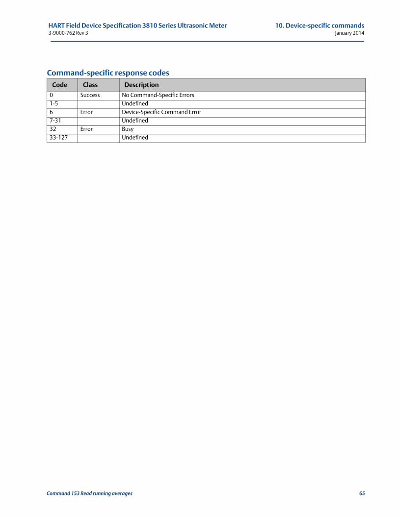
HART Field Device Specification 3810 Series Ultrasonic Meter 10. Device-specific commands3-9000-762 Rev 3 January 2014
Command-specific response codes
Code Class Description
0 Success No Command-Specific Errors1-5 Undefined6 Error Device-Specific Command Error7-31 Undefined32 Error Busy33-127 Undefined
Command 153 Read running averages 65
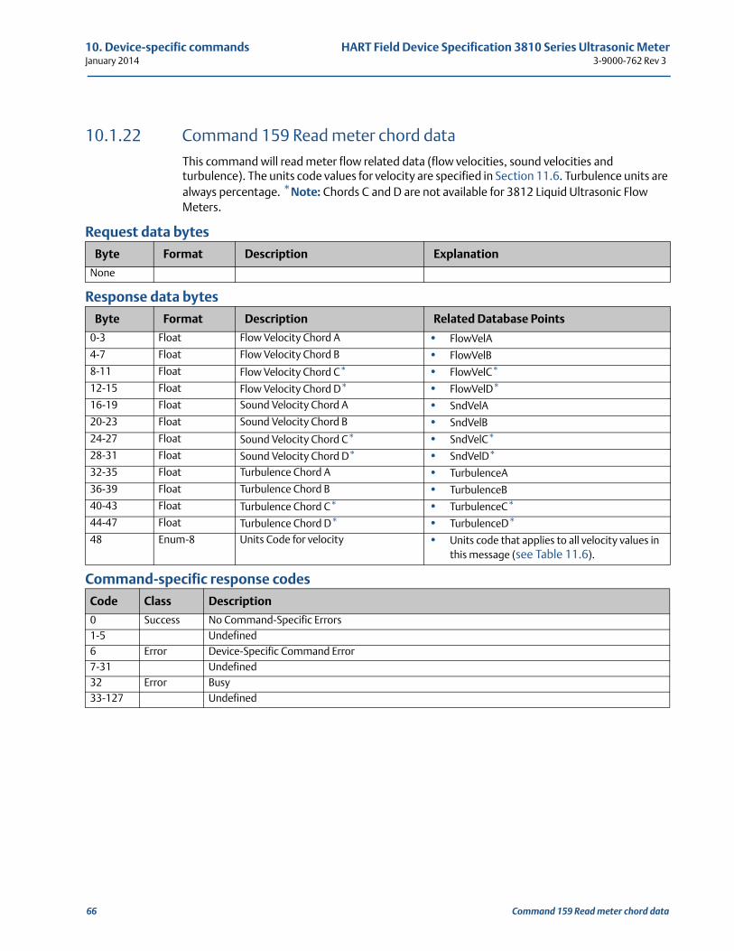
10. Device-specific commands HART Field Device Specification 3810 Series Ultrasonic MeterJanuary 2014 3-9000-762 Rev 3
10.1.22 Command 159 Read meter chord dataThis command will read meter flow related data (flow velocities, sound velocities and turbulence). The units code values for velocity are specified in Section 11.6. Turbulence units are always percentage. *Note: Chords C and D are not available for 3812 Liquid Ultrasonic Flow Meters.
Request data bytes
Response data bytes
Command-specific response codes
Byte Format Description Explanation
None
Byte Format Description Related Database Points
0-3 Float Flow Velocity Chord A • FlowVelA
4-7 Float Flow Velocity Chord B • FlowVelB
8-11 Float Flow Velocity Chord C* • FlowVelC*12-15 Float Flow Velocity Chord D* • FlowVelD*16-19 Float Sound Velocity Chord A • SndVelA
20-23 Float Sound Velocity Chord B • SndVelB
24-27 Float Sound Velocity Chord C* • SndVelC*28-31 Float Sound Velocity Chord D* • SndVelD*32-35 Float Turbulence Chord A • TurbulenceA
36-39 Float Turbulence Chord B • TurbulenceB
40-43 Float Turbulence Chord C* • TurbulenceC*44-47 Float Turbulence Chord D* • TurbulenceD*48 Enum-8 Units Code for velocity • Units code that applies to all velocity values in
this message (see Table 11.6).
Code Class Description
0 Success No Command-Specific Errors1-5 Undefined6 Error Device-Specific Command Error7-31 Undefined32 Error Busy33-127 Undefined
66 Command 159 Read meter chord data
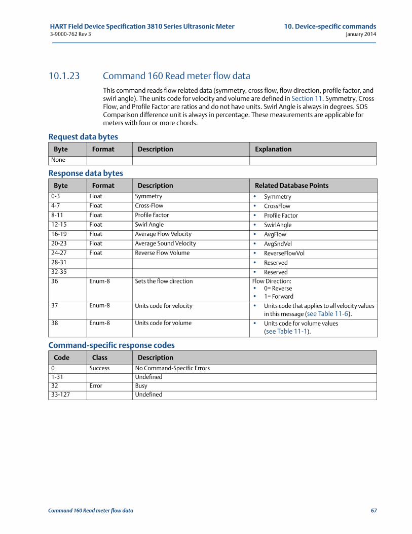
HART Field Device Specification 3810 Series Ultrasonic Meter 10. Device-specific commands3-9000-762 Rev 3 January 2014
10.1.23 Command 160 Read meter flow dataThis command reads flow related data (symmetry, cross flow, flow direction, profile factor, and swirl angle). The units code for velocity and volume are defined in Section 11. Symmetry, Cross Flow, and Profile Factor are ratios and do not have units. Swirl Angle is always in degrees. SOS Comparison difference unit is always in percentage. These measurements are applicable for meters with four or more chords.
Request data bytes
Response data bytes
Command-specific response codes
Byte Format Description Explanation
None
Byte Format Description Related Database Points
0-3 Float Symmetry • Symmetry
4-7 Float Cross-Flow • CrossFlow
8-11 Float Profile Factor • Profile Factor
12-15 Float Swirl Angle • SwirlAngle
16-19 Float Average Flow Velocity • AvgFlow
20-23 Float Average Sound Velocity • AvgSndVel
24-27 Float Reverse Flow Volume • ReverseFlowVol
28-31 • Reserved
32-35 • Reserved
36 Enum-8 Sets the flow direction Flow Direction:• 0= Reverse• 1= Forward
37 Enum-8 Units code for velocity • Units code that applies to all velocity values in this message (see Table 11-6).
38 Enum-8 Units code for volume • Units code for volume values (see Table 11-1).
Code Class Description
0 Success No Command-Specific Errors1-31 Undefined32 Error Busy33-127 Undefined
Command 160 Read meter flow data 67
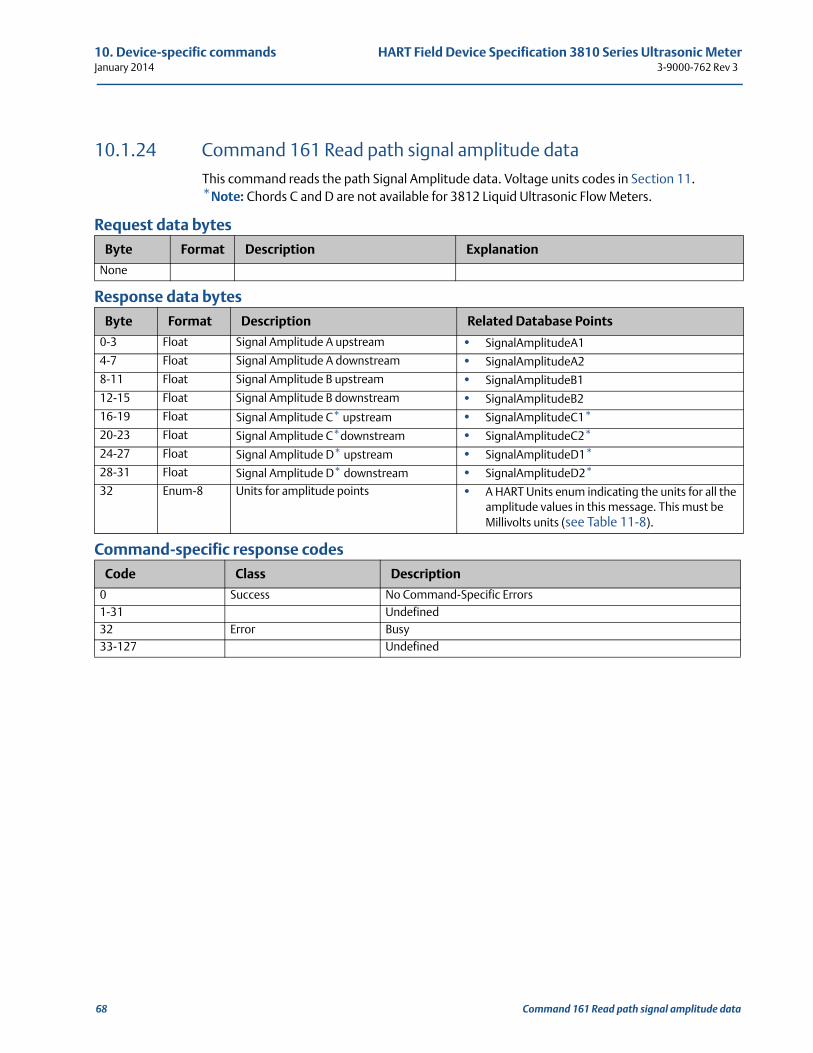
10. Device-specific commands HART Field Device Specification 3810 Series Ultrasonic MeterJanuary 2014 3-9000-762 Rev 3
10.1.24 Command 161 Read path signal amplitude dataThis command reads the path Signal Amplitude data. Voltage units codes in Section 11.*Note: Chords C and D are not available for 3812 Liquid Ultrasonic Flow Meters.
Request data bytes
Response data bytes
Command-specific response codes
Byte Format Description Explanation
None
Byte Format Description Related Database Points
0-3 Float Signal Amplitude A upstream • SignalAmplitudeA1
4-7 Float Signal Amplitude A downstream • SignalAmplitudeA2
8-11 Float Signal Amplitude B upstream • SignalAmplitudeB1
12-15 Float Signal Amplitude B downstream • SignalAmplitudeB2
16-19 Float Signal Amplitude C* upstream • SignalAmplitudeC1*20-23 Float Signal Amplitude C*downstream • SignalAmplitudeC2*24-27 Float Signal Amplitude D* upstream • SignalAmplitudeD1*
28-31 Float Signal Amplitude D* downstream • SignalAmplitudeD2*
32 Enum-8 Units for amplitude points • A HART Units enum indicating the units for all the amplitude values in this message. This must be Millivolts units (see Table 11-8).
Code Class Description
0 Success No Command-Specific Errors1-31 Undefined32 Error Busy33-127 Undefined
68 Command 161 Read path signal amplitude data
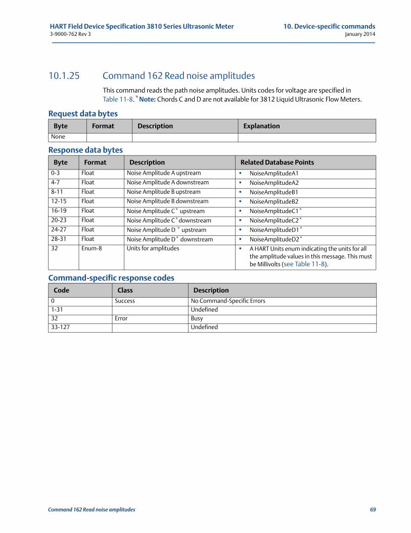
HART Field Device Specification 3810 Series Ultrasonic Meter 10. Device-specific commands3-9000-762 Rev 3 January 2014
10.1.25 Command 162 Read noise amplitudesThis command reads the path noise amplitudes. Units codes for voltage are specified inTable 11-8.*Note: Chords C and D are not available for 3812 Liquid Ultrasonic Flow Meters.
Request data bytes
Response data bytes
Command-specific response codes
Byte Format Description Explanation
None
Byte Format Description Related Database Points
0-3 Float Noise Amplitude A upstream • NoiseAmplitudeA1
4-7 Float Noise Amplitude A downstream • NoiseAmplitudeA2
8-11 Float Noise Amplitude B upstream • NoiseAmplitudeB1
12-15 Float Noise Amplitude B downstream • NoiseAmplitudeB2
16-19 Float Noise Amplitude C* upstream • NoiseAmplitudeC1*
20-23 Float Noise Amplitude C*downstream • NoiseAmplitudeC2*
24-27 Float Noise Amplitude D * upstream • NoiseAmplitudeD1*
28-31 Float Noise Amplitude D* downstream • NoiseAmplitudeD2*
32 Enum-8 Units for amplitudes • A HART Units enum indicating the units for all the amplitude values in this message. This must be Millivolts (see Table 11-8).
Code Class Description
0 Success No Command-Specific Errors1-31 Undefined32 Error Busy33-127 Undefined
Command 162 Read noise amplitudes 69
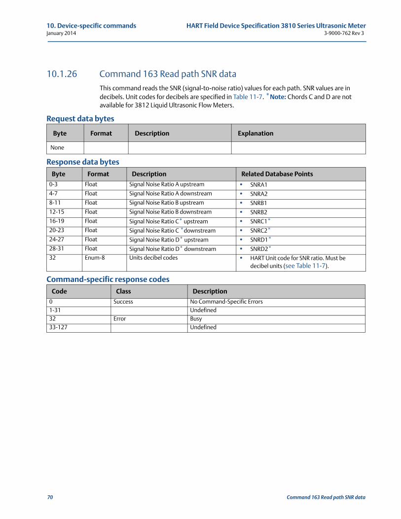
10. Device-specific commands HART Field Device Specification 3810 Series Ultrasonic MeterJanuary 2014 3-9000-762 Rev 3
10.1.26 Command 163 Read path SNR dataThis command reads the SNR (signal-to-noise ratio) values for each path. SNR values are in decibels. Unit codes for decibels are specified in Table 11-7. *Note: Chords C and D are not available for 3812 Liquid Ultrasonic Flow Meters.
Request data bytes
Response data bytes
Command-specific response codes
Byte Format Description Explanation
None
Byte Format Description Related Database Points
0-3 Float Signal Noise Ratio A upstream • SNRA1
4-7 Float Signal Noise Ratio A downstream • SNRA2
8-11 Float Signal Noise Ratio B upstream • SNRB1
12-15 Float Signal Noise Ratio B downstream • SNRB2
16-19 Float Signal Noise Ratio C* upstream • SNRC1*20-23 Float Signal Noise Ratio C *downstream • SNRC2*24-27 Float Signal Noise Ratio D* upstream • SNRD1*28-31 Float Signal Noise Ratio D* downstream • SNRD2*32 Enum-8 Units decibel codes • HART Unit code for SNR ratio. Must be
decibel units (see Table 11-7).
Code Class Description
0 Success No Command-Specific Errors1-31 Undefined32 Error Busy33-127 Undefined
70 Command 163 Read path SNR data
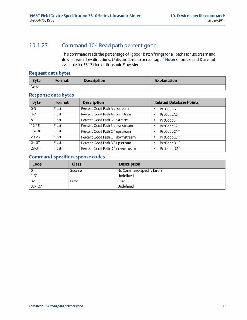
HART Field Device Specification 3810 Series Ultrasonic Meter 10. Device-specific commands3-9000-762 Rev 3 January 2014
10.1.27 Command 164 Read path percent goodThis command reads the percentage of “good” batch firings for all paths for upstream and downstream flow directions. Units are fixed to percentage.*Note: Chords C and D are not available for 3812 Liquid Ultrasonic Flow Meters.
Request data bytes
Response data bytes
Command-specific response codes
Byte Format Description Explanation
None
Byte Format Description Related Database Points
0-3 Float Percent Good Path A upstream • PctGoodA1
4-7 Float Percent Good Path A downstream • PctGoodA2
8-11 Float Percent Good Path B upstream • PctGoodB1
12-15 Float Percent Good Path B downstream • PctGoodB2
16-19 Float Percent Good Path C* upstream • PctGoodC1*20-23 Float Percent Good Path C* downstream • PctGoodC2*24-27 Float Percent Good Path D* upstream • PctGoodD1*28-31 Float Percent Good Path D* downstream • PctGoodD2*
Code Class Description
0 Success No Command-Specific Errors1-31 Undefined32 Error Busy33-127 Undefined
Command 164 Read path percent good 71
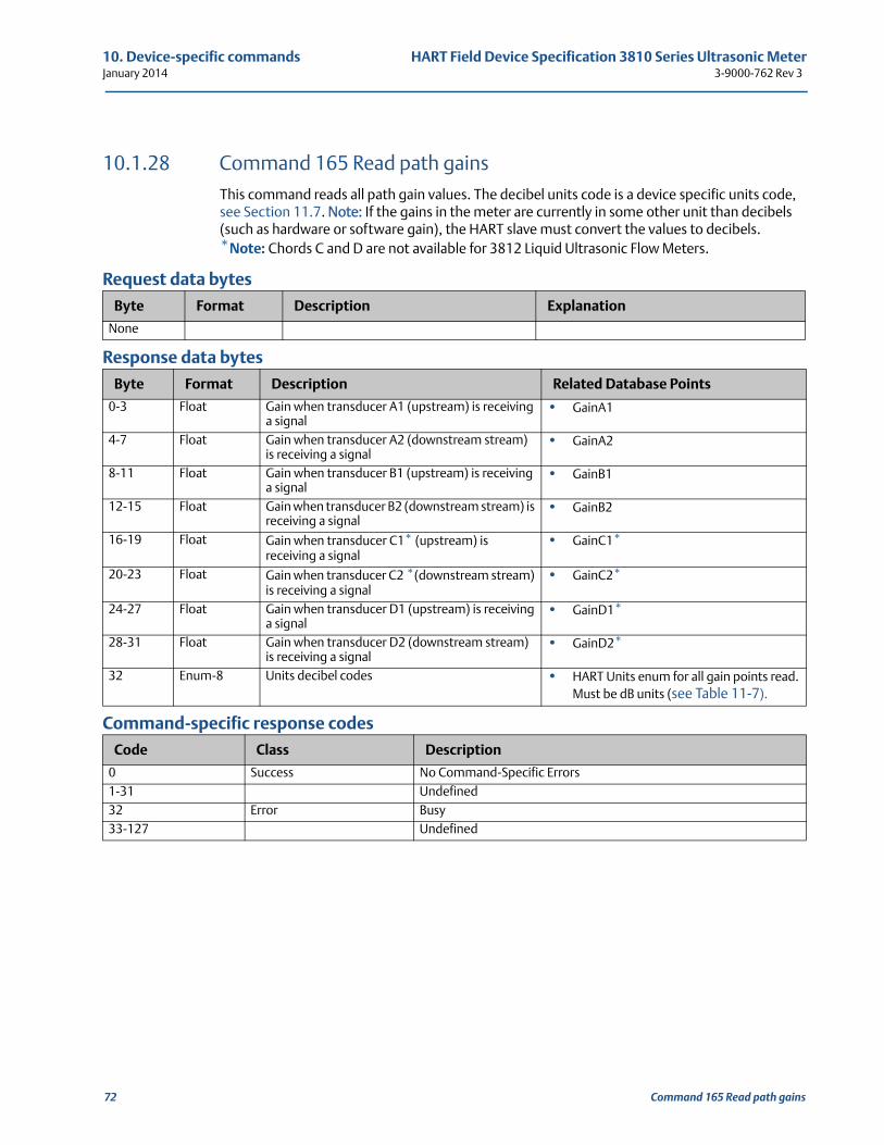
10. Device-specific commands HART Field Device Specification 3810 Series Ultrasonic MeterJanuary 2014 3-9000-762 Rev 3
10.1.28 Command 165 Read path gainsThis command reads all path gain values. The decibel units code is a device specific units code, see Section 11.7. Note: If the gains in the meter are currently in some other unit than decibels (such as hardware or software gain), the HART slave must convert the values to decibels. *Note: Chords C and D are not available for 3812 Liquid Ultrasonic Flow Meters.
Request data bytes
Response data bytes
Command-specific response codes
Byte Format Description Explanation
None
Byte Format Description Related Database Points
0-3 Float Gain when transducer A1 (upstream) is receiving a signal
• GainA1
4-7 Float Gain when transducer A2 (downstream stream) is receiving a signal
• GainA2
8-11 Float Gain when transducer B1 (upstream) is receiving a signal
• GainB1
12-15 Float Gain when transducer B2 (downstream stream) is receiving a signal
• GainB2
16-19 Float Gain when transducer C1* (upstream) is receiving a signal
• GainC1*
20-23 Float Gain when transducer C2 *(downstream stream) is receiving a signal
• GainC2*
24-27 Float Gain when transducer D1 (upstream) is receiving a signal
• GainD1*
28-31 Float Gain when transducer D2 (downstream stream) is receiving a signal
• GainD2*
32 Enum-8 Units decibel codes • HART Units enum for all gain points read. Must be dB units (see Table 11-7).
Code Class Description
0 Success No Command-Specific Errors1-31 Undefined32 Error Busy33-127 Undefined
72 Command 165 Read path gains
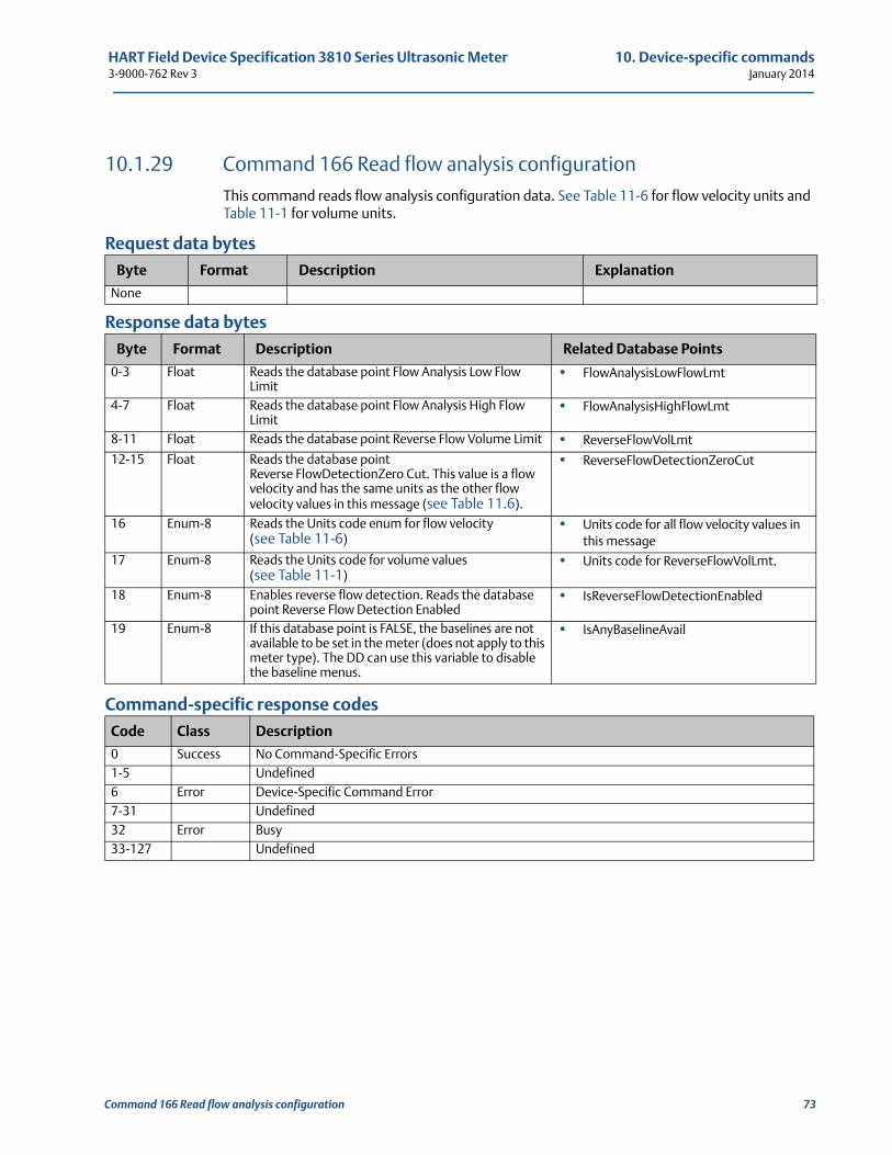
HART Field Device Specification 3810 Series Ultrasonic Meter 10. Device-specific commands3-9000-762 Rev 3 January 2014
10.1.29 Command 166 Read flow analysis configurationThis command reads flow analysis configuration data. See Table 11-6 for flow velocity units and Table 11-1 for volume units.
Request data bytes
Response data bytes
Command-specific response codes
Byte Format Description Explanation
None
Byte Format Description Related Database Points
0-3 Float Reads the database point Flow Analysis Low Flow Limit
• FlowAnalysisLowFlowLmt
4-7 Float Reads the database point Flow Analysis High Flow Limit
• FlowAnalysisHighFlowLmt
8-11 Float Reads the database point Reverse Flow Volume Limit • ReverseFlowVolLmt
12-15 Float Reads the database point Reverse FlowDetectionZero Cut. This value is a flow velocity and has the same units as the other flow velocity values in this message (see Table 11.6).
• ReverseFlowDetectionZeroCut
16 Enum-8 Reads the Units code enum for flow velocity (see Table 11-6)
• Units code for all flow velocity values in this message
17 Enum-8 Reads the Units code for volume values (see Table 11-1)
• Units code for ReverseFlowVolLmt.
18 Enum-8 Enables reverse flow detection. Reads the database point Reverse Flow Detection Enabled
• IsReverseFlowDetectionEnabled
19 Enum-8 If this database point is FALSE, the baselines are not available to be set in the meter (does not apply to this meter type). The DD can use this variable to disable the baseline menus.
• IsAnyBaselineAvail
Code Class Description
0 Success No Command-Specific Errors1-5 Undefined6 Error Device-Specific Command Error7-31 Undefined32 Error Busy33-127 Undefined
Command 166 Read flow analysis configuration 73
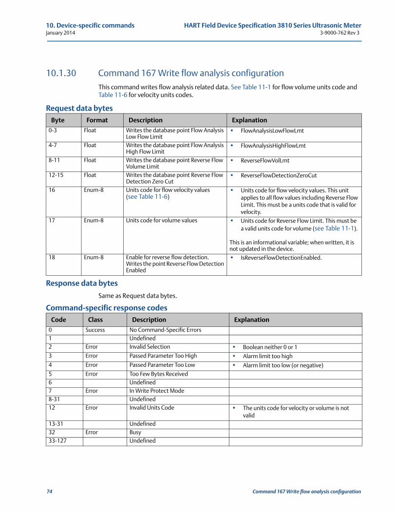
10. Device-specific commands HART Field Device Specification 3810 Series Ultrasonic MeterJanuary 2014 3-9000-762 Rev 3
10.1.30 Command 167 Write flow analysis configurationThis command writes flow analysis related data. See Table 11-1 for flow volume units code and Table 11-6 for velocity units codes.
Request data bytes
Response data bytes
Same as Request data bytes.
Command-specific response codes
Byte Format Description Explanation
0-3 Float Writes the database point Flow Analysis Low Flow Limit
• FlowAnalysisLowFlowLmt
4-7 Float Writes the database point Flow Analysis High Flow Limit
• FlowAnalysisHighFlowLmt
8-11 Float Writes the database point Reverse Flow Volume Limit
• ReverseFlowVolLmt
12-15 Float Writes the database point Reverse Flow Detection Zero Cut
• ReverseFlowDetectionZeroCut
16 Enum-8 Units code for flow velocity values(see Table 11-6)
• Units code for flow velocity values. This unit applies to all flow values including Reverse Flow Limit. This must be a units code that is valid for velocity.
17 Enum-8 Units code for volume values • Units code for Reverse Flow Limit. This must be a valid units code for volume (see Table 11-1).
This is an informational variable; when written, it is not updated in the device.
18 Enum-8 Enable for reverse flow detection. Writes the point Reverse Flow Detection Enabled
• IsReverseFlowDetectionEnabled.
Code Class Description Explanation
0 Success No Command-Specific Errors1 Undefined2 Error Invalid Selection • Boolean neither 0 or 1
3 Error Passed Parameter Too High • Alarm limit too high
4 Error Passed Parameter Too Low • Alarm limit too low (or negative)
5 Error Too Few Bytes Received6 Undefined7 Error In Write Protect Mode8-31 Undefined12 Error Invalid Units Code • The units code for velocity or volume is not
valid13-31 Undefined32 Error Busy33-127 Undefined
74 Command 167 Write flow analysis configuration
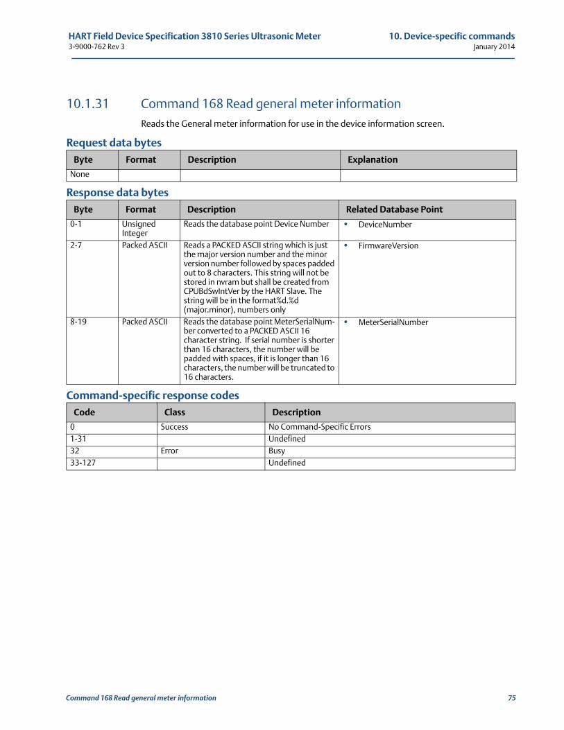
HART Field Device Specification 3810 Series Ultrasonic Meter 10. Device-specific commands3-9000-762 Rev 3 January 2014
10.1.31 Command 168 Read general meter informationReads the General meter information for use in the device information screen.
Request data bytes
Response data bytes
Command-specific response codes
Byte Format Description Explanation
None
Byte Format Description Related Database Point
0-1 Unsigned Integer
Reads the database point Device Number • DeviceNumber
2-7 Packed ASCII Reads a PACKED ASCII string which is just the major version number and the minor version number followed by spaces padded out to 8 characters. This string will not be stored in nvram but shall be created from CPUBdSwIntVer by the HART Slave. The string will be in the format%d.%d (major.minor), numbers only
• FirmwareVersion
8-19 Packed ASCII Reads the database point MeterSerialNum-ber converted to a PACKED ASCII 16 character string. If serial number is shorter than 16 characters, the number will be padded with spaces, if it is longer than 16 characters, the number will be truncated to 16 characters.
• MeterSerialNumber
Code Class Description
0 Success No Command-Specific Errors1-31 Undefined32 Error Busy33-127 Undefined
Command 168 Read general meter information 75
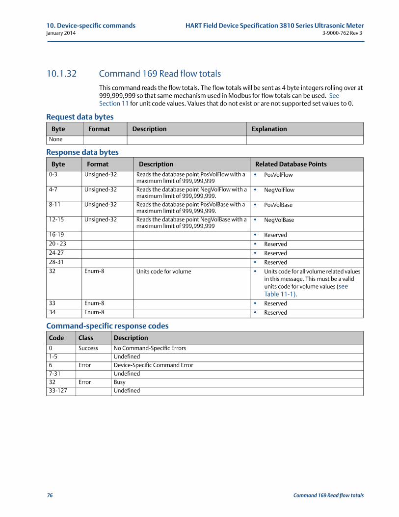
10. Device-specific commands HART Field Device Specification 3810 Series Ultrasonic MeterJanuary 2014 3-9000-762 Rev 3
10.1.32 Command 169 Read flow totalsThis command reads the flow totals. The flow totals will be sent as 4 byte integers rolling over at 999,999,999 so that same mechanism used in Modbus for flow totals can be used. See Section 11 for unit code values. Values that do not exist or are not supported set values to 0.
Request data bytes
Response data bytes
Command-specific response codes
Byte Format Description Explanation
None
Byte Format Description Related Database Points
0-3 Unsigned-32 Reads the database point PosVolFlow with a maximum limit of 999,999,999
• PosVolFlow
4-7 Unsigned-32 Reads the database point NegVolFlow with a maximum limit of 999,999,999.
• NegVolFlow
8-11 Unsigned-32 Reads the database point PosVolBase with a maximum limit of 999,999,999.
• PosVolBase
12-15 Unsigned-32 Reads the database point NegVolBase with a maximum limit of 999,999,999
• NegVolBase
16-19 • Reserved
20 - 23 • Reserved
24-27 • Reserved
28-31 • Reserved
32 Enum-8 Units code for volume • Units code for all volume related values in this message. This must be a valid units code for volume values (see Table 11-1).
33 Enum-8 • Reserved
34 Enum-8 • Reserved
Code Class Description
0 Success No Command-Specific Errors1-5 Undefined6 Error Device-Specific Command Error7-31 Undefined32 Error Busy33-127 Undefined
76 Command 169 Read flow totals
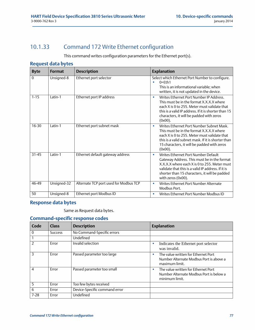
HART Field Device Specification 3810 Series Ultrasonic Meter 10. Device-specific commands3-9000-762 Rev 3 January 2014
Command 172 Write Ethernet configuration 77
10.1.33 Command 172 Write Ethernet configurationThis command writes configuration parameters for the Ethernet port(s).
Request data bytes
Response data bytes
Same as Request data bytes.
Command-specific response codes
Byte Format Description Explanation
0 Unsigned-8 Ethernet port selector Select which Ethernet Port Number to configure.• 0=Eth1
This is an informational variable; when written, it is not updated in the device.
1-15 Latin-1 Ethernet port IP address • Writes Ethernet Port Number IP Address.This must be in the format X.X.X.X where each X is 0 to 255. Meter must validate that this is a valid IP address. If it is shorter than 15 characters, it will be padded with zeros (0x00).
16-30 Latin-1 Ethernet port subnet mask • Writes Ethernet Port Number Subnet Mask. This must be in the format X.X.X.X where each X is 0 to 255. Meter must validate that this is a valid subnet mask. If it is shorter than 15 characters, it will be padded with zeros (0x00).
31-45 Latin-1 Ethernet default gateway address • Writes Ethernet Port Number Default Gateway Address. This must be in the format X.X.X.X where each X is 0 to 255. Meter must validate that this is a valid IP address. If it is shorter than 15 characters, it will be padded with zeros (0x00).
46-49 Unsigned-32 Alternate TCP port used for Modbus TCP • Writes Ethernet Port Number AlternateModbus Port.
50 Unsigned-8 Ethernet port Modbus ID • Writes Ethernet Port Number Modbus ID
Code Class Description Explanation
0 Success No Command-Specific errors1 Undefined2 Error Invalid selection • Indicates the Ethernet port selector
was invalid.3 Error Passed parameter too large • The value written for Ethernet Port
Number Alternate Modbus Port is above a maximum limit.
4 Error Passed parameter too small • The value written for Ethernet Port Number Alternate Modbus Port is below a minimum limit.
5 Error Too few bytes received6 Error Device-Specific command error7-28 Error Undefined
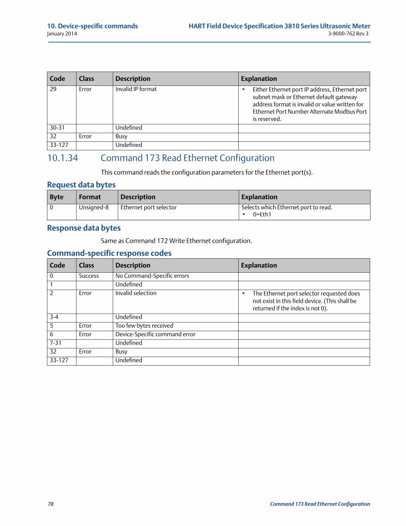
10. Device-specific commands HART Field Device Specification 3810 Series Ultrasonic MeterJanuary 2014 3-9000-762 Rev 3
10.1.34 Command 173 Read Ethernet ConfigurationThis command reads the configuration parameters for the Ethernet port(s).
Request data bytes
Response data bytes
Same as Command 172 Write Ethernet configuration.
Command-specific response codes
29 Error Invalid IP format • Either Ethernet port IP address, Ethernet port subnet mask or Ethernet default gateway address format is invalid or value written forEthernet Port Number Alternate Modbus Port is reserved.
30-31 Undefined32 Error Busy33-127 Undefined
Byte Format Description Explanation
0 Unsigned-8 Ethernet port selector Selects which Ethernet port to read.• 0=Eth1
Code Class Description Explanation
0 Success No Command-Specific errors1 Undefined2 Error Invalid selection • The Ethernet port selector requested does
not exist in this field device. (This shall be returned if the index is not 0).
3-4 Undefined5 Error Too few bytes received6 Error Device-Specific command error7-31 Undefined32 Error Busy33-127 Undefined
Code Class Description Explanation
78 Command 173 Read Ethernet Configuration
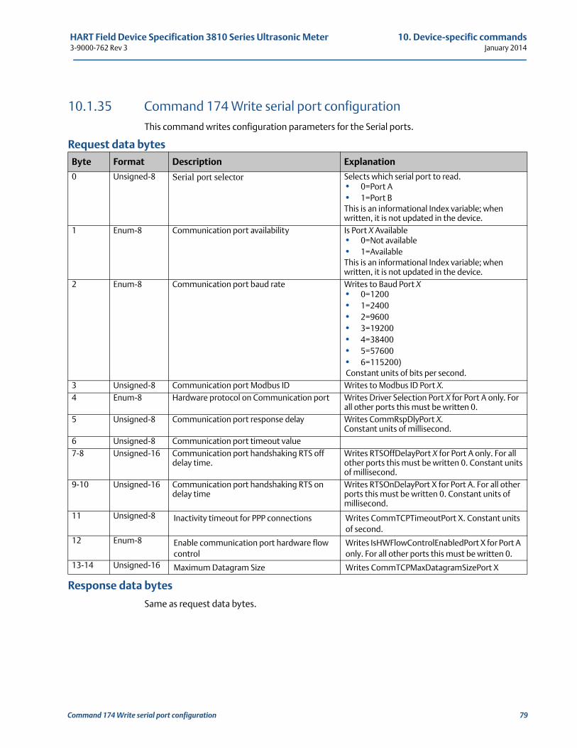
HART Field Device Specification 3810 Series Ultrasonic Meter 10. Device-specific commands3-9000-762 Rev 3 January 2014
10.1.35 Command 174 Write serial port configurationThis command writes configuration parameters for the Serial ports.
Request data bytes
Response data bytes
Same as request data bytes.
Byte Format Description Explanation
0 Unsigned-8 Serial port selector Selects which serial port to read.• 0=Port A• 1=Port BThis is an informational Index variable; when written, it is not updated in the device.
1 Enum-8 Communication port availability Is Port X Available • 0=Not available• 1=AvailableThis is an informational Index variable; when written, it is not updated in the device.
2 Enum-8 Communication port baud rate Writes to Baud Port X• 0=1200• 1=2400• 2=9600• 3=19200• 4=38400• 5=57600• 6=115200) Constant units of bits per second.
3 Unsigned-8 Communication port Modbus ID Writes to Modbus ID Port X.4 Enum-8 Hardware protocol on Communication port Writes Driver Selection Port X for Port A only. For
all other ports this must be written 0.5 Unsigned-8 Communication port response delay Writes CommRspDlyPort X.
Constant units of millisecond.6 Unsigned-8 Communication port timeout value7-8 Unsigned-16 Communication port handshaking RTS off
delay time.Writes RTSOffDelayPort X for Port A only. For all other ports this must be written 0. Constant units of millisecond.
9-10 Unsigned-16 Communication port handshaking RTS on delay time
Writes RTSOnDelayPort X for Port A. For all other ports this must be written 0. Constant units of millisecond.
11 Unsigned-8 Inactivity timeout for PPP connections Writes CommTCPTimeoutPort X. Constant units of second.
12 Enum-8 Enable communication port hardware flow control
Writes IsHWFlowControlEnabledPort X for Port A only. For all other ports this must be written 0.
13-14 Unsigned-16 Maximum Datagram Size Writes CommTCPMaxDatagramSizePort X
Command 174 Write serial port configuration 79
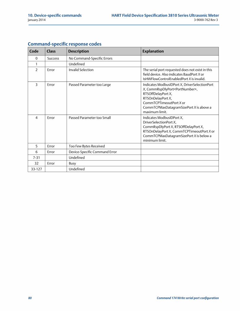
10. Device-specific commands HART Field Device Specification 3810 Series Ultrasonic MeterJanuary 2014 3-9000-762 Rev 3
Command-specific response codes
Code Class Description Explanation
0 Success No Command-Specific Errors
1 Undefined
2 Error Invalid Selection The serial port requested does not exist in this field device. Also indicates BaudPort X or IsHWFlowControlEnabledPort X is invalid.
3 Error Passed Parameter too Large Indicates ModbusIDPort X, DriverSelectionPort X, CommRspDlyPort<PortNumber>, RTSOffDelayPort X,RTSOnDelayPort X,CommTCPTimeoutPort X or CommTCPMaxDatagramSizePort X is above a maximum limit.
4 Error Passed Parameter too Small Indicates ModbusIDPort X,DriverSelectionPort X,CommRspDlyPort X, RTSOffDelayPort X, RTSOnDelayPort X, CommTCPTimeoutPort X or CommTCPMaxDatagramSizePort X is below a minimum limit.
5 Error Too Few Bytes Received
6 Error Device-Specific Command Error
7-31 Undefined
32 Error Busy
33-127 Undefined
80 Command 174 Write serial port configuration
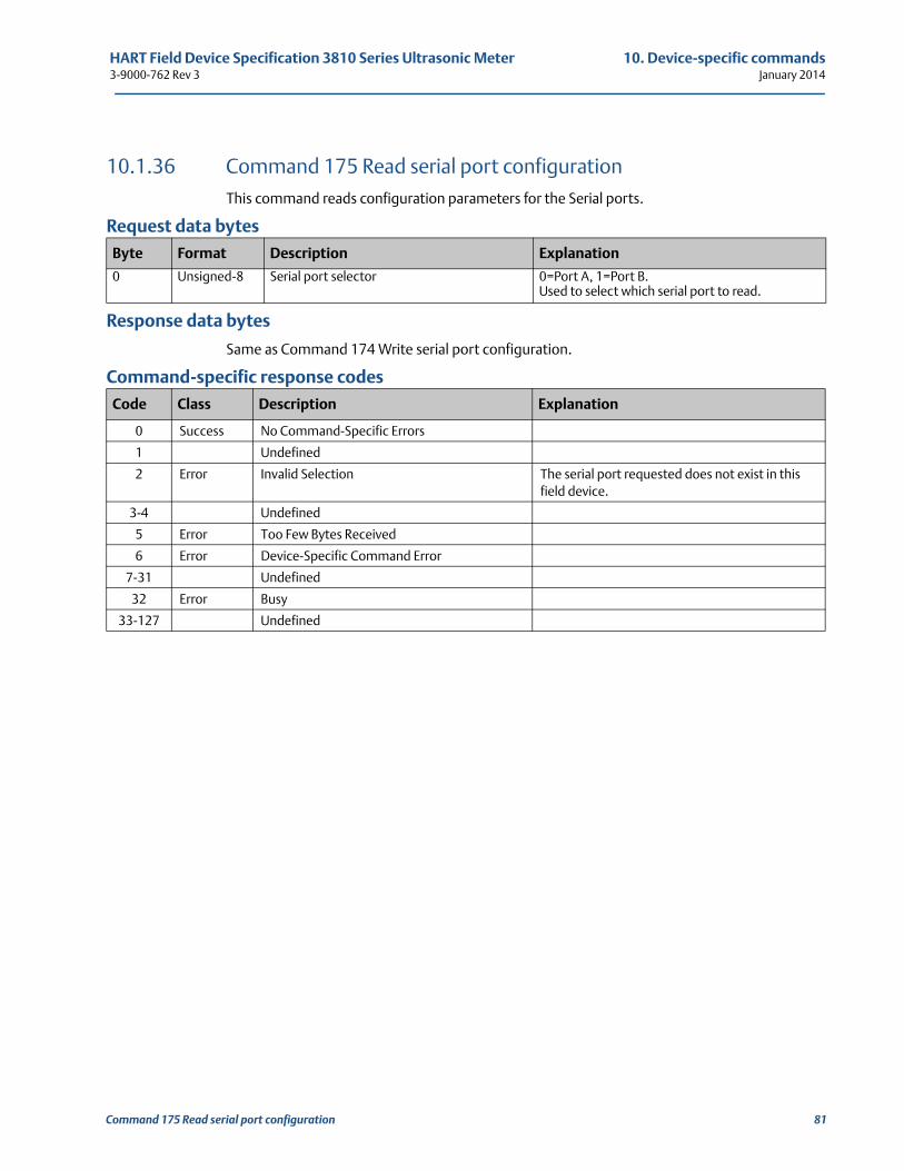
HART Field Device Specification 3810 Series Ultrasonic Meter 10. Device-specific commands3-9000-762 Rev 3 January 2014
10.1.36 Command 175 Read serial port configurationThis command reads configuration parameters for the Serial ports.
Request data bytes
Response data bytes
Same as Command 174 Write serial port configuration.
Command-specific response codes
Byte Format Description Explanation
0 Unsigned-8 Serial port selector 0=Port A, 1=Port B.Used to select which serial port to read.
Code Class Description Explanation
0 Success No Command-Specific Errors
1 Undefined
2 Error Invalid Selection The serial port requested does not exist in this field device.
3-4 Undefined
5 Error Too Few Bytes Received
6 Error Device-Specific Command Error
7-31 Undefined
32 Error Busy
33-127 Undefined
Command 175 Read serial port configuration 81
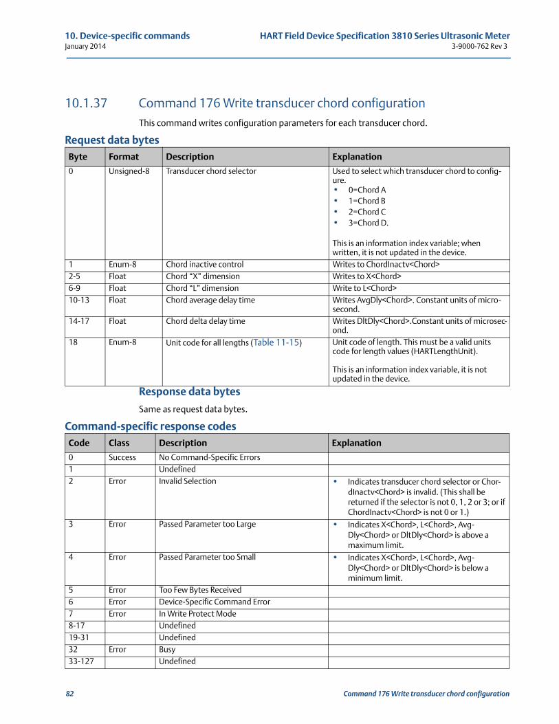
10. Device-specific commands HART Field Device Specification 3810 Series Ultrasonic MeterJanuary 2014 3-9000-762 Rev 3
10.1.37 Command 176 Write transducer chord configurationThis command writes configuration parameters for each transducer chord.
Request data bytes
Response data bytes
Same as request data bytes.
Command-specific response codes
Byte Format Description Explanation
0 Unsigned-8 Transducer chord selector Used to select which transducer chord to config-ure.• 0=Chord A• 1=Chord B• 2=Chord C• 3=Chord D.
This is an information index variable; when written, it is not updated in the device.
1 Enum-8 Chord inactive control Writes to ChordInactv<Chord>2-5 Float Chord “X” dimension Writes to X<Chord>6-9 Float Chord “L” dimension Write to L<Chord>10-13 Float Chord average delay time Writes AvgDly<Chord>. Constant units of micro-
second.14-17 Float Chord delta delay time Writes DltDly<Chord>.Constant units of microsec-
ond.18 Enum-8 Unit code for all lengths (Table 11-15) Unit code of length. This must be a valid units
code for length values (HARTLengthUnit).
This is an information index variable, it is not updated in the device.
Code Class Description Explanation
0 Success No Command-Specific Errors1 Undefined2 Error Invalid Selection • Indicates transducer chord selector or Chor-
dInactv<Chord> is invalid. (This shall be returned if the selector is not 0, 1, 2 or 3; or if ChordInactv<Chord> is not 0 or 1.)
3 Error Passed Parameter too Large • Indicates X<Chord>, L<Chord>, Avg-Dly<Chord> or DltDly<Chord> is above a maximum limit.
4 Error Passed Parameter too Small • Indicates X<Chord>, L<Chord>, Avg-Dly<Chord> or DltDly<Chord> is below a minimum limit.
5 Error Too Few Bytes Received6 Error Device-Specific Command Error7 Error In Write Protect Mode8-17 Undefined19-31 Undefined32 Error Busy33-127 Undefined
82 Command 176 Write transducer chord configuration
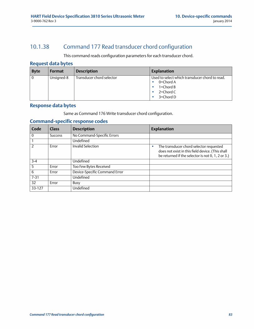
HART Field Device Specification 3810 Series Ultrasonic Meter 10. Device-specific commands3-9000-762 Rev 3 January 2014
10.1.38 Command 177 Read transducer chord configurationThis command reads configuration parameters for each transducer chord.
Request data bytes
Response data bytes
Same as Command 176 Write transducer chord configuration.
Command-specific response codes
Byte Format Description Explanation
0 Unsigned-8 Transducer chord selector Used to select which transducer chord to read.• 0=Chord A• 1=Chord B• 2=Chord C• 3=Chord D
Code Class Description Explanation
0 Success No Command-Specific Errors1 Undefined2 Error Invalid Selection • The transducer chord selector requested
does not exist in this field device. (This shall be returned if the selector is not 0, 1, 2 or 3.)
3-4 Undefined5 Error Too Few Bytes Received6 Error Device-Specific Command Error7-31 Undefined32 Error Busy33-127 Undefined
Command 177 Read transducer chord configuration 83
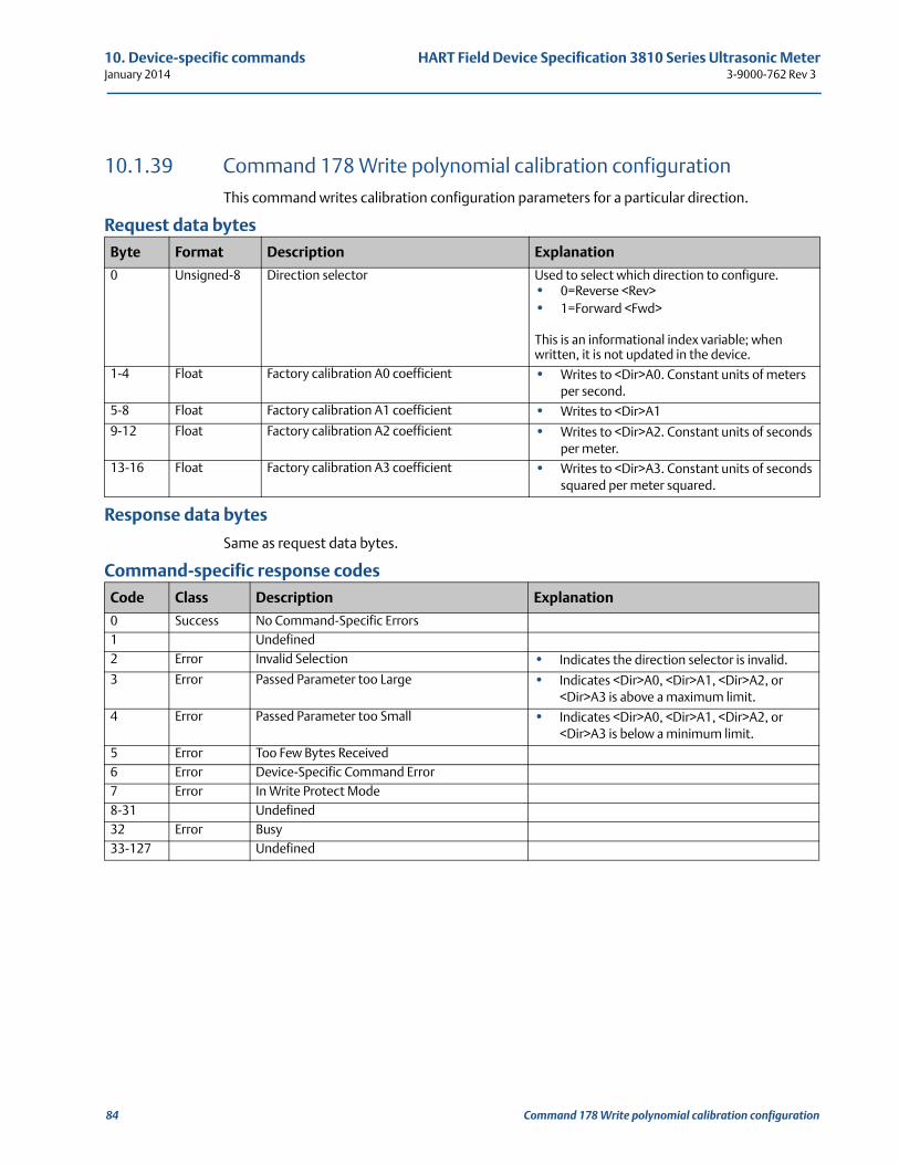
10. Device-specific commands HART Field Device Specification 3810 Series Ultrasonic MeterJanuary 2014 3-9000-762 Rev 3
10.1.39 Command 178 Write polynomial calibration configurationThis command writes calibration configuration parameters for a particular direction.
Request data bytes
Response data bytes
Same as request data bytes.
Command-specific response codes
Byte Format Description Explanation
0 Unsigned-8 Direction selector Used to select which direction to configure.• 0=Reverse <Rev>• 1=Forward <Fwd>
This is an informational index variable; when written, it is not updated in the device.
1-4 Float Factory calibration A0 coefficient • Writes to <Dir>A0. Constant units of meters per second.
5-8 Float Factory calibration A1 coefficient • Writes to <Dir>A1
9-12 Float Factory calibration A2 coefficient • Writes to <Dir>A2. Constant units of seconds per meter.
13-16 Float Factory calibration A3 coefficient • Writes to <Dir>A3. Constant units of seconds squared per meter squared.
Code Class Description Explanation
0 Success No Command-Specific Errors1 Undefined2 Error Invalid Selection • Indicates the direction selector is invalid.
3 Error Passed Parameter too Large • Indicates <Dir>A0, <Dir>A1, <Dir>A2, or <Dir>A3 is above a maximum limit.
4 Error Passed Parameter too Small • Indicates <Dir>A0, <Dir>A1, <Dir>A2, or <Dir>A3 is below a minimum limit.
5 Error Too Few Bytes Received6 Error Device-Specific Command Error7 Error In Write Protect Mode8-31 Undefined32 Error Busy33-127 Undefined
84 Command 178 Write polynomial calibration configuration
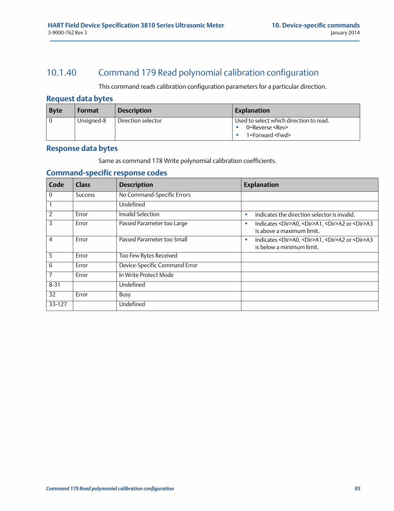
HART Field Device Specification 3810 Series Ultrasonic Meter 10. Device-specific commands3-9000-762 Rev 3 January 2014
A3
A3
10.1.40 Command 179 Read polynomial calibration configurationThis command reads calibration configuration parameters for a particular direction.
Request data bytes
Response data bytes
Same as command 178 Write polynomial calibration coefficients.
Command-specific response codes
Byte Format Description Explanation
0 Unsigned-8 Direction selector Used to select which direction to read.• 0=Reverse <Rev>• 1=Forward <Fwd>
Code Class Description Explanation
0 Success No Command-Specific Errors
1 Undefined
2 Error Invalid Selection • Indicates the direction selector is invalid.
3 Error Passed Parameter too Large • Indicates <Dir>A0, <Dir>A1, <Dir>A2 or <Dir>is above a maximum limit.
4 Error Passed Parameter too Small • Indicates <Dir>A0, <Dir>A1, <Dir>A2 or <Dir>is below a minimum limit.
5 Error Too Few Bytes Received
6 Error Device-Specific Command Error
7 Error In Write Protect Mode
8-31 Undefined
32 Error Busy
33-127 Undefined
Command 179 Read polynomial calibration configuration 85
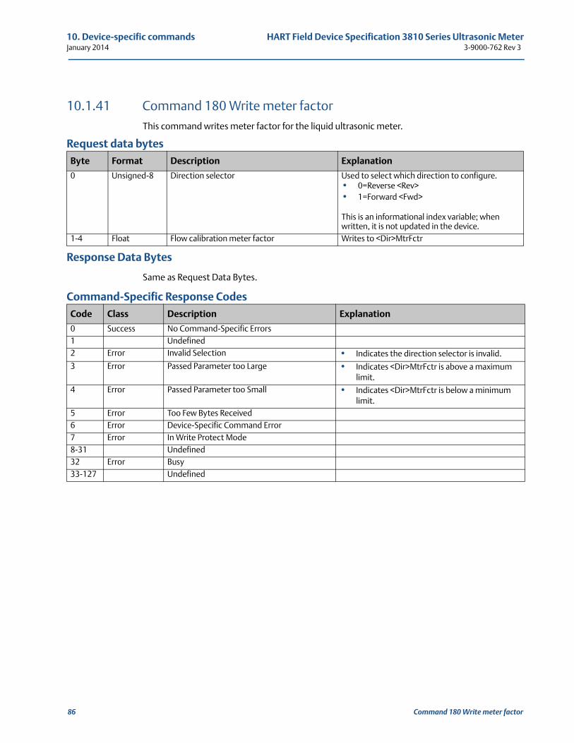
10. Device-specific commands HART Field Device Specification 3810 Series Ultrasonic MeterJanuary 2014 3-9000-762 Rev 3
10.1.41 Command 180 Write meter factorThis command writes meter factor for the liquid ultrasonic meter.
Request data bytes
Response Data Bytes
Same as Request Data Bytes.
Command-Specific Response Codes
Byte Format Description Explanation
0 Unsigned-8 Direction selector Used to select which direction to configure.• 0=Reverse <Rev>• 1=Forward <Fwd>
This is an informational index variable; when written, it is not updated in the device.
1-4 Float Flow calibration meter factor Writes to <Dir>MtrFctr
Code Class Description Explanation
0 Success No Command-Specific Errors1 Undefined2 Error Invalid Selection • Indicates the direction selector is invalid.
3 Error Passed Parameter too Large • Indicates <Dir>MtrFctr is above a maximum limit.
4 Error Passed Parameter too Small • Indicates <Dir>MtrFctr is below a minimum limit.
5 Error Too Few Bytes Received6 Error Device-Specific Command Error7 Error In Write Protect Mode8-31 Undefined32 Error Busy33-127 Undefined
86 Command 180 Write meter factor
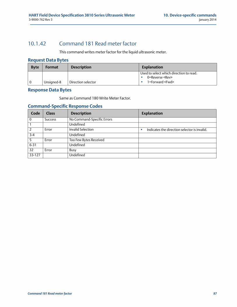
HART Field Device Specification 3810 Series Ultrasonic Meter 10. Device-specific commands3-9000-762 Rev 3 January 2014
10.1.42 Command 181 Read meter factorThis command writes meter factor for the liquid ultrasonic meter.
Request Data Bytes
Response Data Bytes
Same as Command 180 Write Meter Factor.
Command-Specific Response Codes
Byte Format Description Explanation
0 Unsigned-8 Direction selector
Used to select which direction to read.• 0=Reverse <Rev> • 1=Forward <Fwd>
Code Class Description Explanation
0 Success No Command-Specific Errors1 Undefined2 Error Invalid Selection • Indicates the direction selector is invalid.
3-4 Undefined5 Error Too Few Bytes Received6-31 Undefined32 Error Busy33-127 Undefined
Command 181 Read meter factor 87
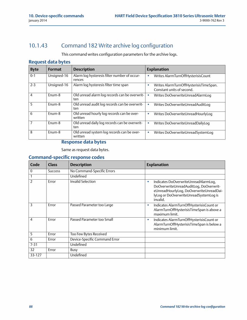
10. Device-specific commands HART Field Device Specification 3810 Series Ultrasonic MeterJanuary 2014 3-9000-762 Rev 3
10.1.43 Command 182 Write archive log configurationThis command writes configuration parameters for the archive logs.
Request data bytes
Response data bytes
Same as request data bytes.
Command-specific response codes
Byte Format Description Explanation
0-1 Unsigned-16 Alarm log hysteresis filter number of occur-rences
• Writes AlarmTurnOffHysterisisCount
2-3 Unsigned-16 Alarm log hysteresis filter time span • Writes AlarmTurnOffHysterisisTimeSpan. Constant units of second.
4 Enum-8 Old unread alarm log records can be overwrit-ten
• Writes DoOverwriteUnreadAlarmLog
5 Enum-8 Old unread audit log records can be overwrit-ten
• Writes DoOverwriteUnreadAuditLog
6 Enum-8 Old unread hourly log records can be over-written
• Writes DoOverwriteUnreadHourlyLog
7 Enum-8 Old unread daily log records can be overwrit-ten
• Writes DoOverwriteUnreadDailyLog
8 Enum-8 Old unread system log records can be over-written
• Writes DoOverwriteUnreadSystemLog
Code Class Description Explanation
0 Success No Command-Specific Errors1 Undefined2 Error Invalid Selection • Indicates DoOverwriteUnreadAlarmLog,
DoOverwriteUnreadAuditLog, DoOverwrit-eUnreadHourlyLog, DoOverwriteUnreadDai-lyLog or DoOverwriteUnreadSystemLog is invalid.
3 Error Passed Parameter too Large • Indicates AlarmTurnOffHysterisisCount or AlarmTurnOffHysterisisTimeSpan is above a maximum limit.
4 Error Passed Parameter too Small • Indicates AlarmTurnOffHysterisisCount or AlarmTurnOffHysterisisTimeSpan is below a minimum limit.
5 Error Too Few Bytes Received6 Error Device-Specific Command Error7-31 Undefined32 Error Busy33-127 Undefined
88 Command 182 Write archive log configuration
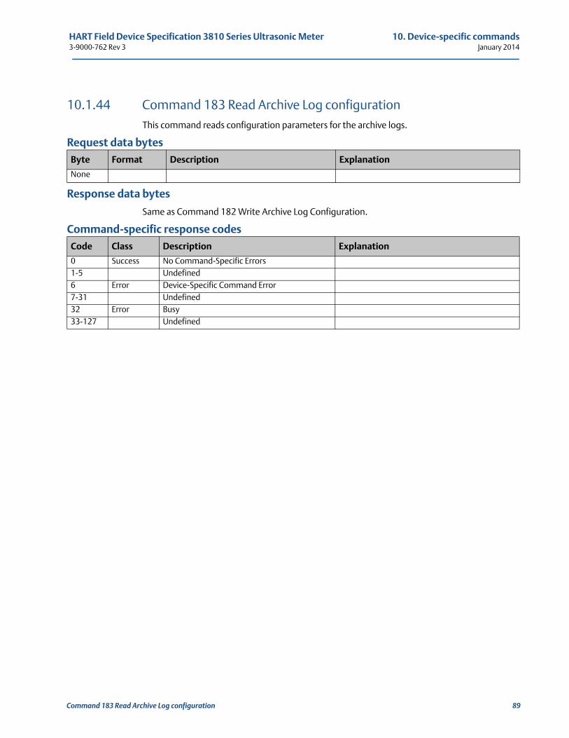
HART Field Device Specification 3810 Series Ultrasonic Meter 10. Device-specific commands3-9000-762 Rev 3 January 2014
10.1.44 Command 183 Read Archive Log configurationThis command reads configuration parameters for the archive logs.
Request data bytes
Response data bytes
Same as Command 182 Write Archive Log Configuration.
Command-specific response codes
Byte Format Description Explanation
None
Code Class Description Explanation
0 Success No Command-Specific Errors1-5 Undefined6 Error Device-Specific Command Error7-31 Undefined32 Error Busy33-127 Undefined
Command 183 Read Archive Log configuration 89
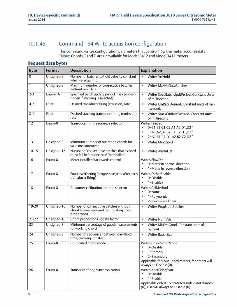
10. Device-specific commands HART Field Device Specification 3810 Series Ultrasonic MeterJanuary 2014 3-9000-762 Rev 3
90 Command 184 Write acquisition configuration
10.1.45 Command 184 Write acquisition configurationThis command writes configuration parameters that control how the meter acquires data. *Note: Chords C and D are unavailable for Model 3412 and Model 3411 meters.
Request data bytes
Byte Format Description Explanation
0 Unsigned-8 Number of batches to hold velocity constant when re-acquiring.
• Writes VelHold
1 Unsigned-8 Maximum number of consecutive batches without new data
• Writes MaxNoDataBatches
2-3 Enum-16 Specified batch update period (may be over-ridden if stacking is selected)
• Writes SpecBatchUpdtPeriod. Constant Units of millisecond.
4-7 Float Desired transducer firing (emission) rate • Writes EmRateDesired. Constant units of mil-lisecond.
8-11 Float Desired stacking transducer firing (emission) rate
• Writes StackEmRateDesired. Constant units of millisecond.
12 Enum-8 Transducer firing sequence selector Writes FireSeq • 0=B1,B2,C1,C2,A1,A2,D1,D2*• 1=A1,A2,B1,B2,C1,C2,D1,D2*• 2=A1,B1,C1,D1,A2,B2,C2,D2*
13 Unsigned-8 Minimum number of operating chords for valid measurement
• Writes MinChord
14-15 Unsigned-16 Number of consecutive batches that a chord must fail before declared "hard failed"
• Writes AlarmDef
16 Enum-8 Meter installed backwards control Writes FlowDir • 0=Meter in normal direction• 1=Meter in reverse direction
17 Enum-8 Enables dithering (progressive jitter after each transducer firing)
Writes DitherEnable • 0=Disable• 1=Enable)
18 Enum-8 Customer-calibration method selector Writes CalMethod • 0=None• 1=Polynomial• 2=Piece-wise linear
19-20 Unsigned-16 Number of consecutive batches without chord failures required for updating chord proportions.
• Writes PropUpdtBatches
21-22 Unsigned-16 Chord proportions update factor • Writes NumVals
23 Unsigned-8 Minimum percentage of good measurements for working chord
• Writes MinPctGood. Constant units of percent.
24 Unsigned-8 Number of sequences between gain/hold time/tracking updates
• Writes BatchSize
25 Enum-8 Co-located meter mode Writes ColocMeterMode • 0=Disable• 1=Primary• 2=SecondaryApplicable for Four Chord meters, for others will always be Disable (0).
26 Enum-8 Transducer firing synchronization Writes XdcrFiringSync • 0=Disable• 1=EnableApplicable only if ColocMeterMode is not disabled (0), else will always be Disable (0).
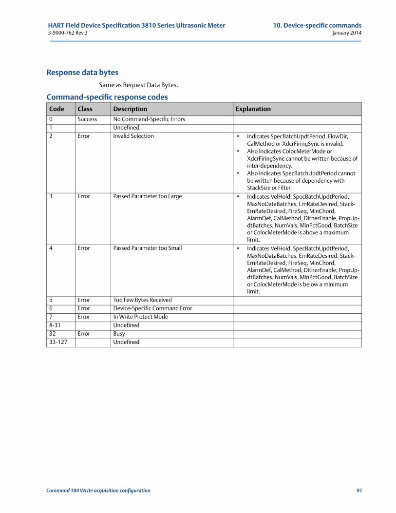
HART Field Device Specification 3810 Series Ultrasonic Meter 10. Device-specific commands3-9000-762 Rev 3 January 2014
Command 184 Write acquisition configuration 91
Response data bytes
Same as Request Data Bytes.
Command-specific response codes
Code Class Description Explanation
0 Success No Command-Specific Errors1 Undefined2 Error Invalid Selection • Indicates SpecBatchUpdtPeriod, FlowDir,
CalMethod or XdcrFiringSync is invalid.• Also indicates ColocMeterMode or
XdcrFiringSync cannot be written because of inter-dependency.
• Also indicates SpecBatchUpdtPeriod cannot be written because of dependency with StackSize or Filter.
3 Error Passed Parameter too Large • Indicates VelHold, SpecBatchUpdtPeriod, MaxNoDataBatches, EmRateDesired, Stack-EmRateDesired, FireSeq, MinChord, AlarmDef, CalMethod, DitherEnable, PropUp-dtBatches, NumVals, MinPctGood, BatchSize or ColocMeterMode is above a maximum limit.
4 Error Passed Parameter too Small • Indicates VelHold, SpecBatchUpdtPeriod, MaxNoDataBatches, EmRateDesired, Stack-EmRateDesired, FireSeq, MinChord, AlarmDef, CalMethod, DitherEnable, PropUp-dtBatches, NumVals, MinPctGood, BatchSize or ColocMeterMode is below a minimum limit.
5 Error Too Few Bytes Received6 Error Device-Specific Command Error7 Error In Write Protect Mode8-31 Undefined32 Error Busy33-127 Undefined
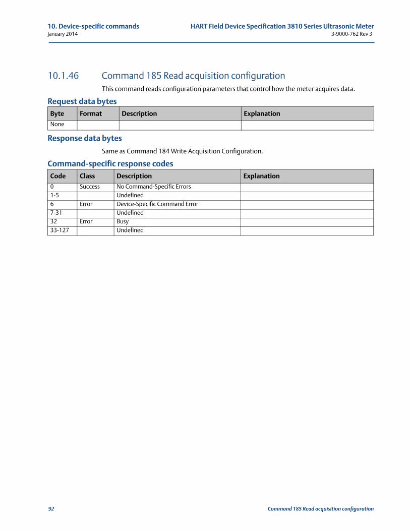
10. Device-specific commands HART Field Device Specification 3810 Series Ultrasonic MeterJanuary 2014 3-9000-762 Rev 3
10.1.46 Command 185 Read acquisition configurationThis command reads configuration parameters that control how the meter acquires data.
Request data bytes
Response data bytes
Same as Command 184 Write Acquisition Configuration.
Command-specific response codes
Byte Format Description Explanation
None
Code Class Description Explanation
0 Success No Command-Specific Errors1-5 Undefined6 Error Device-Specific Command Error7-31 Undefined32 Error Busy33-127 Undefined
92 Command 185 Read acquisition configuration
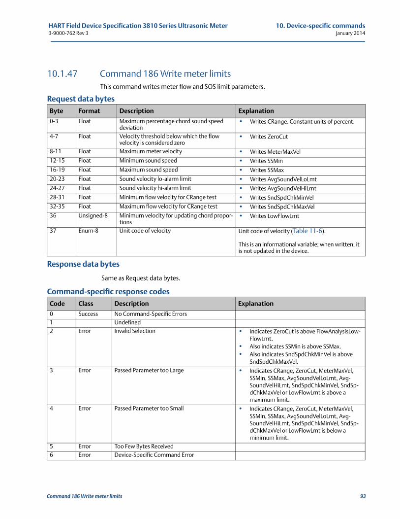
HART Field Device Specification 3810 Series Ultrasonic Meter 10. Device-specific commands3-9000-762 Rev 3 January 2014
10.1.47 Command 186 Write meter limitsThis command writes meter flow and SOS limit parameters.
Request data bytes
Response data bytes
Same as Request data bytes.
Command-specific response codes
Byte Format Description Explanation
0-3 Float Maximum percentage chord sound speed deviation
• Writes CRange. Constant units of percent.
4-7 Float Velocity threshold below which the flow velocity is considered zero
• Writes ZeroCut
8-11 Float Maximum meter velocity • Writes MeterMaxVel
12-15 Float Minimum sound speed • Writes SSMin
16-19 Float Maximum sound speed • Writes SSMax
20-23 Float Sound velocity lo-alarm limit • Writes AvgSoundVelLoLmt
24-27 Float Sound velocity hi-alarm limit • Writes AvgSoundVelHiLmt
28-31 Float Minimum flow velocity for CRange test • Writes SndSpdChkMinVel
32-35 Float Maximum flow velocity for CRange test • Writes SndSpdChkMaxVel
36 Unsigned-8 Minimum velocity for updating chord propor-tions
• Writes LowFlowLmt
37 Enum-8 Unit code of velocity Unit code of velocity (Table 11-6).
This is an informational variable; when written, it is not updated in the device.
Code Class Description Explanation
0 Success No Command-Specific Errors1 Undefined2 Error Invalid Selection • Indicates ZeroCut is above FlowAnalysisLow-
FlowLmt. • Also indicates SSMin is above SSMax.• Also indicates SndSpdChkMinVel is above
SndSpdChkMaxVel.3 Error Passed Parameter too Large • Indicates CRange, ZeroCut, MeterMaxVel,
SSMin, SSMax, AvgSoundVelLoLmt, Avg-SoundVelHiLmt, SndSpdChkMinVel, SndSp-dChkMaxVel or LowFlowLmt is above a maximum limit.
4 Error Passed Parameter too Small • Indicates CRange, ZeroCut, MeterMaxVel, SSMin, SSMax, AvgSoundVelLoLmt, Avg-SoundVelHiLmt, SndSpdChkMinVel, SndSp-dChkMaxVel or LowFlowLmt is below a minimum limit.
5 Error Too Few Bytes Received6 Error Device-Specific Command Error
Command 186 Write meter limits 93
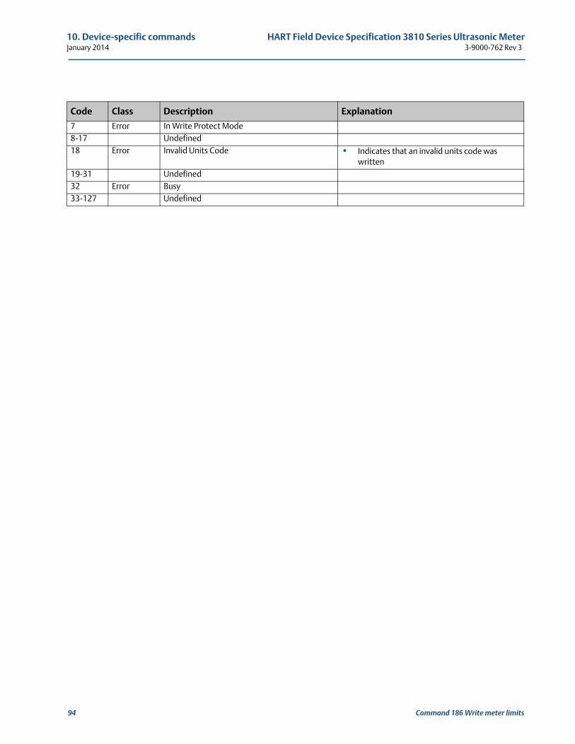
10. Device-specific commands HART Field Device Specification 3810 Series Ultrasonic MeterJanuary 2014 3-9000-762 Rev 3
7 Error In Write Protect Mode8-17 Undefined18 Error Invalid Units Code • Indicates that an invalid units code was
written19-31 Undefined32 Error Busy33-127 Undefined
Code Class Description Explanation
94 Command 186 Write meter limits
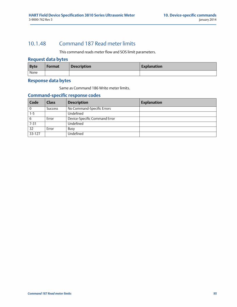
HART Field Device Specification 3810 Series Ultrasonic Meter 10. Device-specific commands3-9000-762 Rev 3 January 2014
10.1.48 Command 187 Read meter limitsThis command reads meter flow and SOS limit parameters.
Request data bytes
Response data bytes
Same as Command 186 Write meter limits.
Command-specific response codes
Byte Format Description Explanation
None
Code Class Description Explanation
0 Success No Command-Specific Errors1-5 Undefined6 Error Device-Specific Command Error7-31 Undefined32 Error Busy33-127 Undefined
Command 187 Read meter limits 95
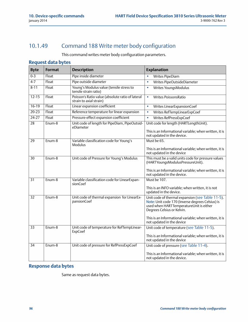
10. Device-specific commands HART Field Device Specification 3810 Series Ultrasonic MeterJanuary 2014 3-9000-762 Rev 3
10.1.49 Command 188 Write meter body configurationThis command writes meter body configuration parameters.
Request data bytes
Response data bytes
Same as request data bytes.
Byte Format Description Explanation
0-3 Float Pipe inside diameter • Writes PipeDiam
4-7 Float Pipe outside diameter • Writes PipeOutsideDiameter
8-11 Float Young’s Modulus value (tensile stress to tensile strain ratio)
• Writes YoungsModulus
12-15 Float Poisson's Ratio value (absolute ratio of lateral strain to axial strain)
• Writes PoissonsRatio
16-19 Float Linear expansion coefficient • Writes LinearExpansionCoef
20-23 Float Reference temperature for linear expansion • Writes RefTempLinearExpCoef
24-27 Float Pressure-effect expansion coefficient • Writes RefPressExpCoef
28 Enum-8 Unit code of length for PipeDiam, PipeOutsid-eDiameter
Unit code for length (HARTLengthUnit).
This is an Informational variable; when written, it is not updated in the device.
29 Enum-8 Variable classification code for Young’s Modulus
Must be 65.
This is an Informational variable; when written, it is not updated in the device
30 Enum-8 Unit code of Pressure for Young’s Modulus This must be a valid units code for pressure values (HARTYoungsModulusPressureUnit).
This is an Informational variable; when written, it is not updated in the device.
31 Enum-8 Variable classification code for LinearExpan-sionCoef
Must be 107.
This is an INFO variable; when written, it is not updated in the device.
32 Enum-8 Unit code of thermal expansion for LinearEx-pansionCoef
Unit code of thermal expansion (see Table 11-5).Note: Unit code 170 (Inverse degrees Celsius) is used when HARTTemperatureUnit is either Degrees Celsius or Kelvin.
This is an Informational variable; when written, it is not updated in the device
33 Enum-8 Unit code of temperature for RefTempLinear-ExpCoef
Unit code of temperature (see Table 11-5).
This is an Informational variable; when written, it is not updated in the device
34 Enum-8 Unit code of pressure for RefPressExpCoef Unit code of pressure (see Table 11-4).
This is an Informational variable; when written, it is not updated in the device.
96 Command 188 Write meter body configuration
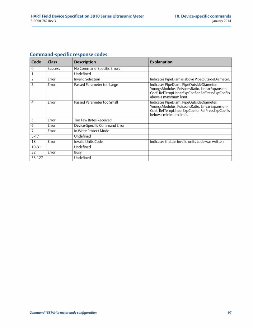
HART Field Device Specification 3810 Series Ultrasonic Meter 10. Device-specific commands3-9000-762 Rev 3 January 2014
Command-specific response codes
Code Class Description Explanation
0 Success No Command-Specific Errors1 Undefined2 Error Invalid Selection Indicates PipeDiam is above PipeOutsideDiameter.3 Error Passed Parameter too Large Indicates PipeDiam, PipeOutsideDiameter,
YoungsModulus, PoissonsRatio, LinearExpansion-Coef, RefTempLinearExpCoef or RefPressExpCoef is above a maximum limit.
4 Error Passed Parameter too Small Indicates PipeDiam, PipeOutsideDiameter, YoungsModulus, PoissonsRatio, LinearExpansion-Coef, RefTempLinearExpCoef or RefPressExpCoef is below a minimum limit.
5 Error Too Few Bytes Received6 Error Device-Specific Command Error7 Error In Write Protect Mode8-17 Undefined18 Error Invalid Units Code Indicates that an invalid units code was written19-31 Undefined32 Error Busy33-127 Undefined
Command 188 Write meter body configuration 97
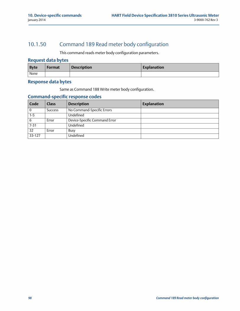
10. Device-specific commands HART Field Device Specification 3810 Series Ultrasonic MeterJanuary 2014 3-9000-762 Rev 3
10.1.50 Command 189 Read meter body configurationThis command reads meter body configuration parameters.
Request data bytes
Response data bytes
Same as Command 188 Write meter body configuration.
Command-specific response codes
Byte Format Description Explanation
None
Code Class Description Explanation
0 Success No Command-Specific Errors1-5 Undefined6 Error Device-Specific Command Error7-31 Undefined32 Error Busy33-127 Undefined
98 Command 189 Read meter body configuration
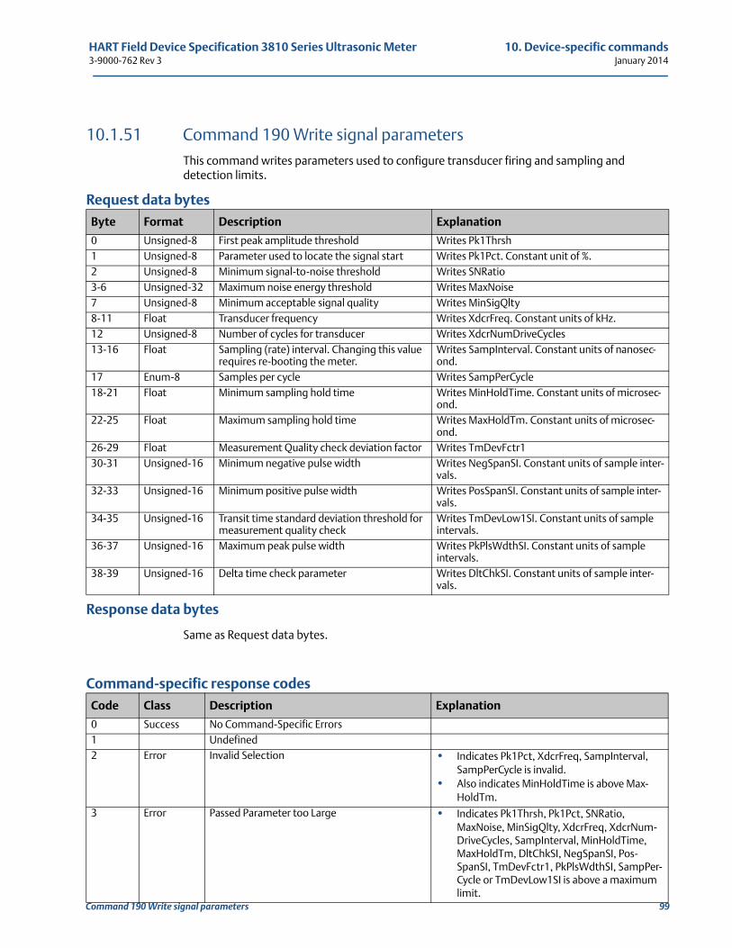
HART Field Device Specification 3810 Series Ultrasonic Meter 10. Device-specific commands3-9000-762 Rev 3 January 2014
Command 190 Write signal parameters 99
10.1.51 Command 190 Write signal parametersThis command writes parameters used to configure transducer firing and sampling and detection limits.
Request data bytes
Response data bytes
Same as Request data bytes.
Command-specific response codes
Byte Format Description Explanation
0 Unsigned-8 First peak amplitude threshold Writes Pk1Thrsh1 Unsigned-8 Parameter used to locate the signal start Writes Pk1Pct. Constant unit of %.2 Unsigned-8 Minimum signal-to-noise threshold Writes SNRatio3-6 Unsigned-32 Maximum noise energy threshold Writes MaxNoise7 Unsigned-8 Minimum acceptable signal quality Writes MinSigQlty8-11 Float Transducer frequency Writes XdcrFreq. Constant units of kHz.12 Unsigned-8 Number of cycles for transducer Writes XdcrNumDriveCycles13-16 Float Sampling (rate) interval. Changing this value
requires re-booting the meter.Writes SampInterval. Constant units of nanosec-ond.
17 Enum-8 Samples per cycle Writes SampPerCycle18-21 Float Minimum sampling hold time Writes MinHoldTime. Constant units of microsec-
ond.22-25 Float Maximum sampling hold time Writes MaxHoldTm. Constant units of microsec-
ond.26-29 Float Measurement Quality check deviation factor Writes TmDevFctr130-31 Unsigned-16 Minimum negative pulse width Writes NegSpanSI. Constant units of sample inter-
vals.32-33 Unsigned-16 Minimum positive pulse width Writes PosSpanSI. Constant units of sample inter-
vals.34-35 Unsigned-16 Transit time standard deviation threshold for
measurement quality checkWrites TmDevLow1SI. Constant units of sample intervals.
36-37 Unsigned-16 Maximum peak pulse width Writes PkPlsWdthSI. Constant units of sample intervals.
38-39 Unsigned-16 Delta time check parameter Writes DltChkSI. Constant units of sample inter-vals.
Code Class Description Explanation
0 Success No Command-Specific Errors1 Undefined2 Error Invalid Selection • Indicates Pk1Pct, XdcrFreq, SampInterval,
SampPerCycle is invalid.• Also indicates MinHoldTime is above Max-
HoldTm.3 Error Passed Parameter too Large • Indicates Pk1Thrsh, Pk1Pct, SNRatio,
MaxNoise, MinSigQlty, XdcrFreq, XdcrNum-DriveCycles, SampInterval, MinHoldTime, MaxHoldTm, DltChkSI, NegSpanSI, Pos-SpanSI, TmDevFctr1, PkPlsWdthSI, SampPer-Cycle or TmDevLow1SI is above a maximum limit.
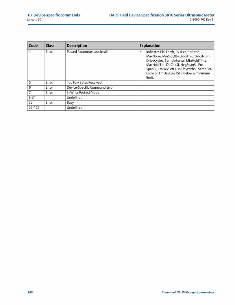
10. Device-specific commands HART Field Device Specification 3810 Series Ultrasonic MeterJanuary 2014 3-9000-762 Rev 3
100 Command 190 Write signal parameters
4 Error Passed Parameter too Small • Indicates Pk1Thrsh, Pk1Pct, SNRatio, MaxNoise, MinSigQlty, XdcrFreq, XdcrNum-DriveCycles, SampInterval, MinHoldTime, MaxHoldTm, DltChkSI, NegSpanSI, Pos-SpanSI, TmDevFctr1, PkPlsWdthSI, SampPer-Cycle or TmDevLow1SI is below a minimum limit.
5 Error Too Few Bytes Received6 Error Device-Specific Command Error7 Error In Write Protect Mode8-31 Undefined32 Error Busy33-127 Undefined
Code Class Description Explanation
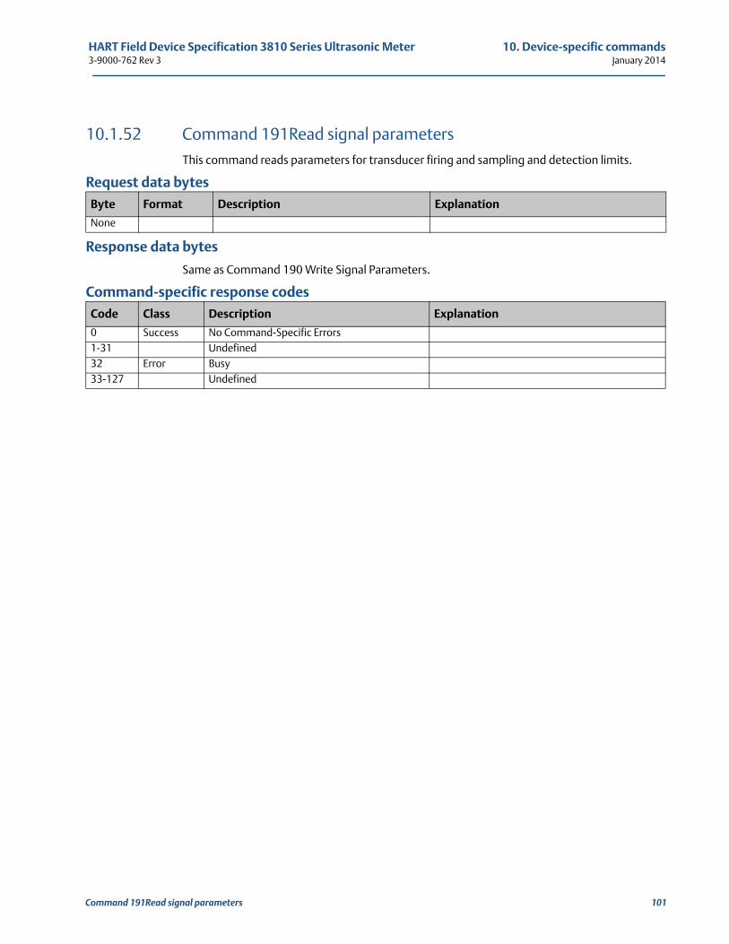
HART Field Device Specification 3810 Series Ultrasonic Meter 10. Device-specific commands3-9000-762 Rev 3 January 2014
Command 191Read signal parameters 101
10.1.52 Command 191Read signal parametersThis command reads parameters for transducer firing and sampling and detection limits.
Request data bytes
Response data bytes
Same as Command 190 Write Signal Parameters.
Command-specific response codes
Byte Format Description Explanation
None
Code Class Description Explanation
0 Success No Command-Specific Errors1-31 Undefined32 Error Busy33-127 Undefined
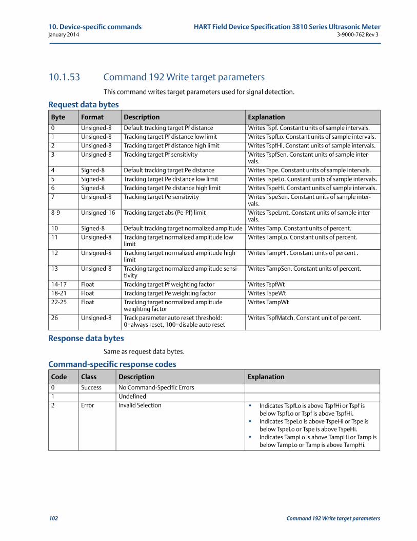
10. Device-specific commands HART Field Device Specification 3810 Series Ultrasonic MeterJanuary 2014 3-9000-762 Rev 3
10.1.53 Command 192 Write target parametersThis command writes target parameters used for signal detection.
Request data bytes
Response data bytes
Same as request data bytes.
Command-specific response codes
Byte Format Description Explanation
0 Unsigned-8 Default tracking target Pf distance Writes Tspf. Constant units of sample intervals.1 Unsigned-8 Tracking target Pf distance low limit Writes TspfLo. Constant units of sample intervals.2 Unsigned-8 Tracking target Pf distance high limit Writes TspfHi. Constant units of sample intervals.3 Unsigned-8 Tracking target Pf sensitivity Writes TspfSen. Constant units of sample inter-
vals.4 Signed-8 Default tracking target Pe distance Writes Tspe. Constant units of sample intervals.5 Signed-8 Tracking target Pe distance low limit Writes TspeLo. Constant units of sample intervals.6 Signed-8 Tracking target Pe distance high limit Writes TspeHi. Constant units of sample intervals.7 Unsigned-8 Tracking target Pe sensitivity Writes TspeSen. Constant units of sample inter-
vals.8-9 Unsigned-16 Tracking target abs (Pe-Pf) limit Writes TspeLmt. Constant units of sample inter-
vals.10 Signed-8 Default tracking target normalized amplitude Writes Tamp. Constant units of percent.11 Unsigned-8 Tracking target normalized amplitude low
limitWrites TampLo. Constant units of percent.
12 Unsigned-8 Tracking target normalized amplitude high limit
Writes TampHi. Constant units of percent .
13 Unsigned-8 Tracking target normalized amplitude sensi-tivity
Writes TampSen. Constant units of percent.
14-17 Float Tracking target Pf weighting factor Writes TspfWt18-21 Float Tracking target Pe weighting factor Writes TspeWt22-25 Float Tracking target normalized amplitude
weighting factorWrites TampWt
26 Unsigned-8 Track parameter auto reset threshold: 0=always reset, 100=disable auto reset
Writes TspfMatch. Constant unit of percent.
Code Class Description Explanation
0 Success No Command-Specific Errors1 Undefined2 Error Invalid Selection • Indicates TspfLo is above TspfHi or Tspf is
below TspfLo or Tspf is above TspfHi.• Indicates TspeLo is above TspeHi or Tspe is
below TspeLo or Tspe is above TspeHi.• Indicates TampLo is above TampHi or Tamp is
below TampLo or Tamp is above TampHi.
102 Command 192 Write target parameters
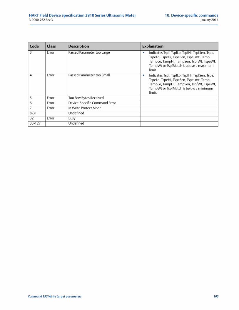
HART Field Device Specification 3810 Series Ultrasonic Meter 10. Device-specific commands3-9000-762 Rev 3 January 2014
3 Error Passed Parameter too Large • Indicates Tspf, TspfLo, TspfHi, TspfSen, Tspe, TspeLo, TspeHi, TspeSen, TspeLmt, Tamp, TampLo, TampHi, TampSen, TspfWt, TspeWt, TampWt or TspfMatch is above a maximum limit.
4 Error Passed Parameter too Small • Indicates Tspf, TspfLo, TspfHi, TspfSen, Tspe, TspeLo, TspeHi, TspeSen, TspeLmt, Tamp, TampLo, TampHi, TampSen, TspfWt, TspeWt, TampWt or TspfMatch is below a minimum limit.
5 Error Too Few Bytes Received6 Error Device-Specific Command Error7 Error In Write Protect Mode8-31 Undefined32 Error Busy33-127 Undefined
Code Class Description Explanation
Command 192 Write target parameters 103
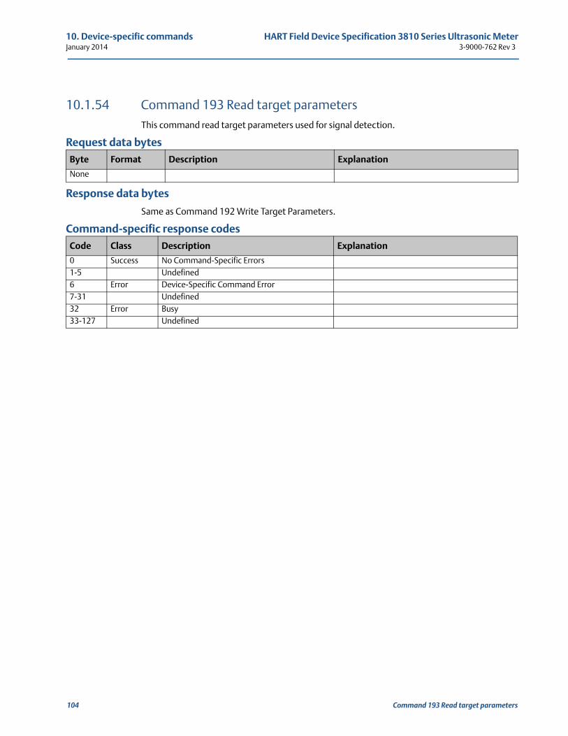
10. Device-specific commands HART Field Device Specification 3810 Series Ultrasonic MeterJanuary 2014 3-9000-762 Rev 3
10.1.54 Command 193 Read target parametersThis command read target parameters used for signal detection.
Request data bytes
Response data bytes
Same as Command 192 Write Target Parameters.
Command-specific response codes
Byte Format Description Explanation
None
Code Class Description Explanation
0 Success No Command-Specific Errors1-5 Undefined6 Error Device-Specific Command Error7-31 Undefined32 Error Busy33-127 Undefined
104 Command 193 Read target parameters
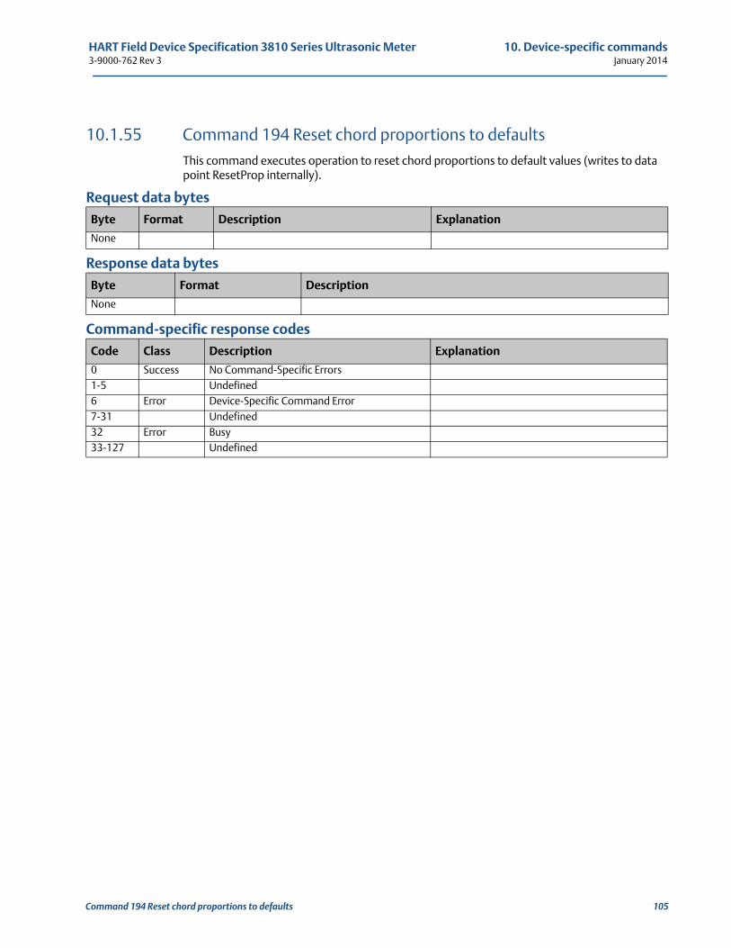
HART Field Device Specification 3810 Series Ultrasonic Meter 10. Device-specific commands3-9000-762 Rev 3 January 2014
10.1.55 Command 194 Reset chord proportions to defaultsThis command executes operation to reset chord proportions to default values (writes to data point ResetProp internally).
Request data bytes
Response data bytes
Command-specific response codes
Byte Format Description Explanation
None
Byte Format Description
None
Code Class Description Explanation
0 Success No Command-Specific Errors1-5 Undefined6 Error Device-Specific Command Error7-31 Undefined32 Error Busy33-127 Undefined
Command 194 Reset chord proportions to defaults 105
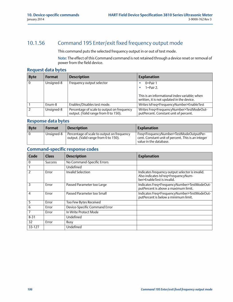
10. Device-specific commands HART Field Device Specification 3810 Series Ultrasonic MeterJanuary 2014 3-9000-762 Rev 3
10.1.56 Command 195 Enter/exit fixed frequency output modeThis command puts the selected frequency output in or out of test mode.
Note: The effect of this Command command is not retained through a device reset or removal of power from the field device.
Request data bytes
Response data bytes
Command-specific response codes
Byte Format Description Explanation
0 Unsigned-8 Frequency output selector • 0=Pair 1• 1=Pair 2.
This is an informational index variable; when written, it is not updated in the device.
1 Enum-8 Enables/Disables test mode. Writes IsFreq<FrequencyNumber>EnableTest2 Unsigned-8 Percentage of scale to output on frequency
output. (Valid range from 0 to 150).Writes Freq<FrequencyNumber>TestModeOut-putPercent. Constant unit of percent.
Byte Format Description Explanation
0 Unsigned-8 Percentage of scale to output on frequency output. (Valid range from 0 to 150).
Freq<FrequencyNumber>TestModeOutputPer-cent. Constant unit of percent. This is an integer value in the database.
Code Class Description Explanation
0 Success No Command-Specific Errors1 Undefined2 Error Invalid Selection Indicates frequency output selector is invalid.
Also indicates IsFreq<FrequencyNum-ber>EnableTest is invalid.
3 Error Passed Parameter too Large Indicates Freq<FrequencyNumber>TestModeOut-putPercent is above a maximum limit.
4 Error Passed Parameter too Small Indicates Freq<FrequencyNumber>TestModeOut-putPercent is below a minimum limit.
5 Error Too Few Bytes Received6 Error Device-Specific Command Error7 Error In Write Protect Mode8-31 Undefined32 Error Busy33-127 Undefined
106 Command 195 Enter/exit fixed frequency output mode
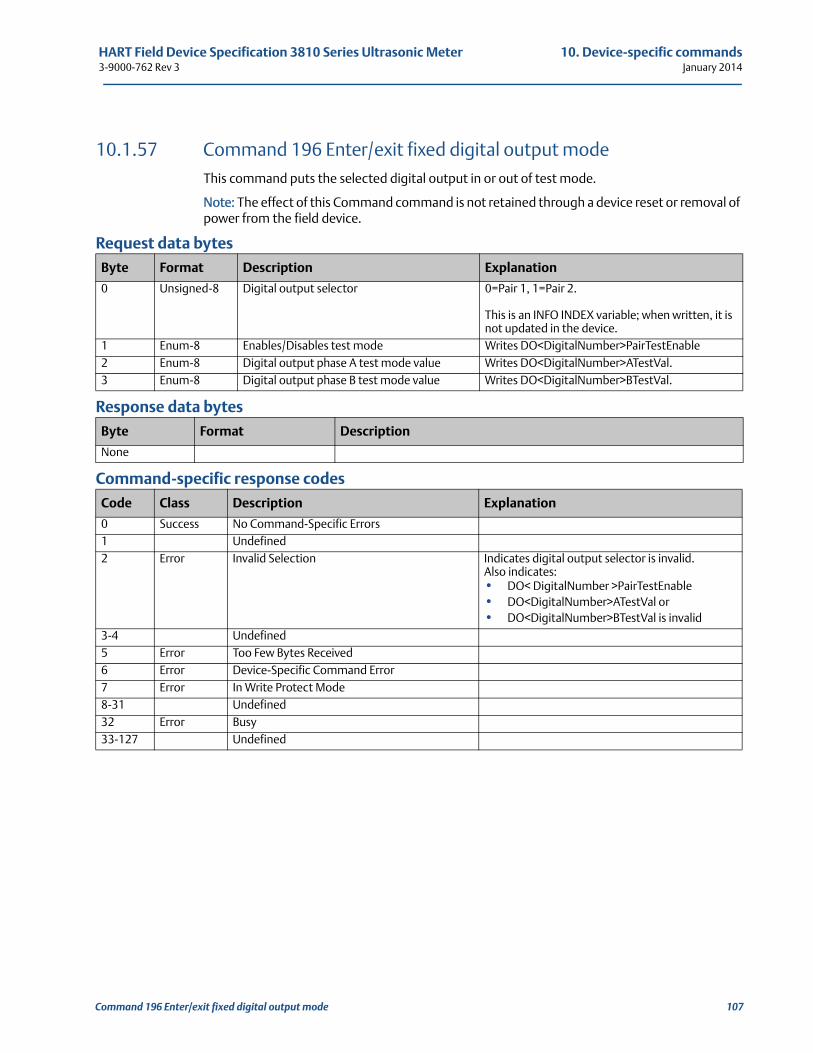
HART Field Device Specification 3810 Series Ultrasonic Meter 10. Device-specific commands3-9000-762 Rev 3 January 2014
10.1.57 Command 196 Enter/exit fixed digital output modeThis command puts the selected digital output in or out of test mode.
Note: The effect of this Command command is not retained through a device reset or removal of power from the field device.
Request data bytes
Response data bytes
Command-specific response codes
Byte Format Description Explanation
0 Unsigned-8 Digital output selector 0=Pair 1, 1=Pair 2.
This is an INFO INDEX variable; when written, it is not updated in the device.
1 Enum-8 Enables/Disables test mode Writes DO<DigitalNumber>PairTestEnable2 Enum-8 Digital output phase A test mode value Writes DO<DigitalNumber>ATestVal. 3 Enum-8 Digital output phase B test mode value Writes DO<DigitalNumber>BTestVal.
Byte Format Description
None
Code Class Description Explanation
0 Success No Command-Specific Errors1 Undefined2 Error Invalid Selection Indicates digital output selector is invalid.
Also indicates:• DO< DigitalNumber >PairTestEnable• DO<DigitalNumber>ATestVal or • DO<DigitalNumber>BTestVal is invalid
3-4 Undefined5 Error Too Few Bytes Received6 Error Device-Specific Command Error7 Error In Write Protect Mode8-31 Undefined32 Error Busy33-127 Undefined
Command 196 Enter/exit fixed digital output mode 107
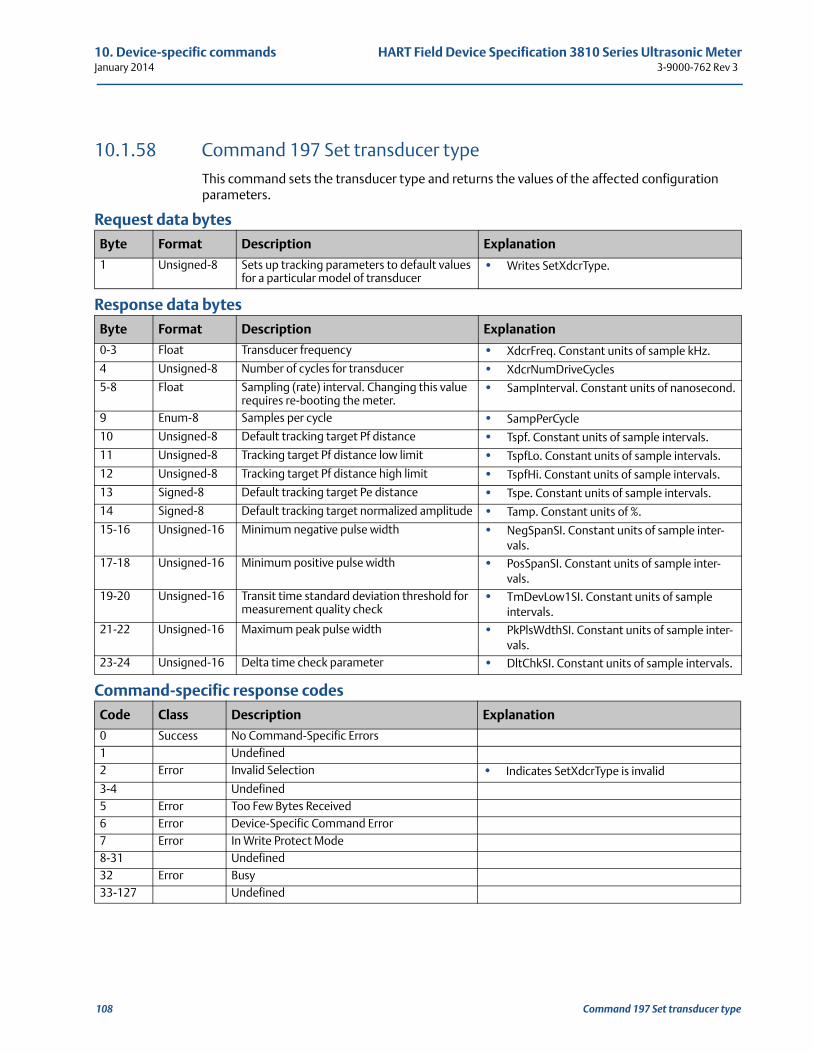
10. Device-specific commands HART Field Device Specification 3810 Series Ultrasonic MeterJanuary 2014 3-9000-762 Rev 3
10.1.58 Command 197 Set transducer typeThis command sets the transducer type and returns the values of the affected configuration parameters.
Request data bytes
Response data bytes
Command-specific response codes
Byte Format Description Explanation
1 Unsigned-8 Sets up tracking parameters to default values for a particular model of transducer
• Writes SetXdcrType.
Byte Format Description Explanation
0-3 Float Transducer frequency • XdcrFreq. Constant units of sample kHz.
4 Unsigned-8 Number of cycles for transducer • XdcrNumDriveCycles
5-8 Float Sampling (rate) interval. Changing this value requires re-booting the meter.
• SampInterval. Constant units of nanosecond.
9 Enum-8 Samples per cycle • SampPerCycle
10 Unsigned-8 Default tracking target Pf distance • Tspf. Constant units of sample intervals.
11 Unsigned-8 Tracking target Pf distance low limit • TspfLo. Constant units of sample intervals.
12 Unsigned-8 Tracking target Pf distance high limit • TspfHi. Constant units of sample intervals.
13 Signed-8 Default tracking target Pe distance • Tspe. Constant units of sample intervals.
14 Signed-8 Default tracking target normalized amplitude • Tamp. Constant units of %.
15-16 Unsigned-16 Minimum negative pulse width • NegSpanSI. Constant units of sample inter-vals.
17-18 Unsigned-16 Minimum positive pulse width • PosSpanSI. Constant units of sample inter-vals.
19-20 Unsigned-16 Transit time standard deviation threshold for measurement quality check
• TmDevLow1SI. Constant units of sample intervals.
21-22 Unsigned-16 Maximum peak pulse width • PkPlsWdthSI. Constant units of sample inter-vals.
23-24 Unsigned-16 Delta time check parameter • DltChkSI. Constant units of sample intervals.
Code Class Description Explanation
0 Success No Command-Specific Errors1 Undefined2 Error Invalid Selection • Indicates SetXdcrType is invalid
3-4 Undefined5 Error Too Few Bytes Received6 Error Device-Specific Command Error7 Error In Write Protect Mode8-31 Undefined32 Error Busy33-127 Undefined
108 Command 197 Set transducer type
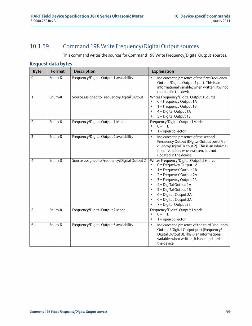
HART Field Device Specification 3810 Series Ultrasonic Meter 10. Device-specific commands3-9000-762 Rev 3 January 2014
10.1.59 Command 198 Write Frequency/Digital Output sources This command writes the sources for Command 198 Write Frequency/Digital Output sources.
Request data bytes
Byte Format Description Explanation
0 Enum-8 Frequency/Digital Output 1 availability • Indicates the presence of the first Frequency Output /Digital Output 1 port. This is an informational variable; when written, it is not updated in the device
1 Enum-8 Source assigned to Frequency/Digital Output 1 Writes Frequency/Digital Output 1Source • 0 = Frequency Output 1A• 1 = Frequency Output 1B• 4 = Digital Output 1A• 5 = Digital Output 1B
2 Enum-8 Frequency/Digital Output 1 Mode Frequency/Digital Output 1Mode• 0 = TTL• 1 = open collector
3 Enum-8 Frequency/Digital Output 2 availability • Indicates the presence of the second Frequency Output /Digital Output port (Fre-quency/Digital Output 2). This is an informa-tional variable; when written, it is not updated in the device.
4 Enum-8 Source assigned to Frequency/Digital Output 2 Writes Frequency/Digital Output 2Source• 0 = FrequeNcy Output 1A• 1 = FrequencY Output 1B• 2 = FrequencY Output 2A• 3 = Frequency Output 2B• 4 = DigiTal Output 1A• 5 = DigiTal Output 1B• 6 = DigitaL Output 2A• 6 = DigitaL Output 2A• 7 = Digital Output 2B
5 Enum-8 Frequency/Digital Output 2 Mode Frequency/Digital Output 1Mode• 0 = TTL• 1 = open collector
6 Enum-8 Frequency/Digital Output 3 availability • Indicates the presence of the third Frequency Output / Digital Output port (Frequency/Digital Output 3).This is an informational variable; when written, it is not updated in the device
Command 198 Write Frequency/Digital Output sources 109
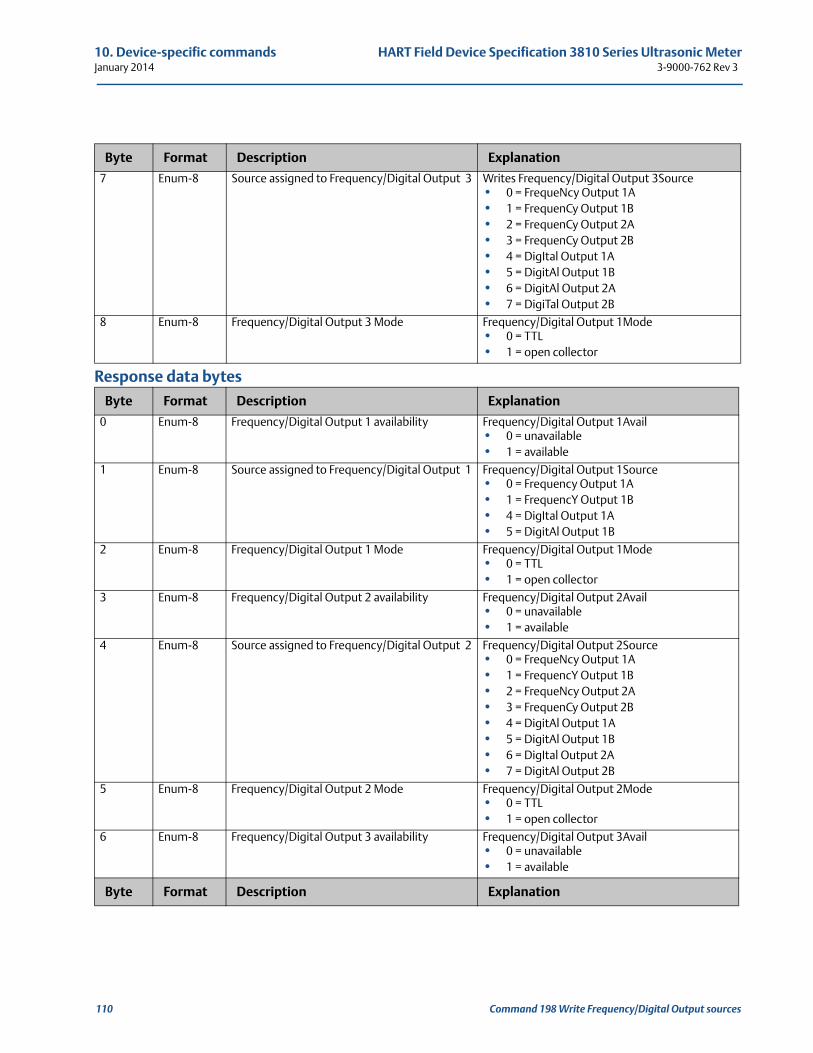
10. Device-specific commands HART Field Device Specification 3810 Series Ultrasonic MeterJanuary 2014 3-9000-762 Rev 3
Response data bytes
7 Enum-8 Source assigned to Frequency/Digital Output 3 Writes Frequency/Digital Output 3Source• 0 = FrequeNcy Output 1A• 1 = FrequenCy Output 1B• 2 = FrequenCy Output 2A• 3 = FrequenCy Output 2B• 4 = DigItal Output 1A• 5 = DigitAl Output 1B• 6 = DigitAl Output 2A• 7 = DigiTal Output 2B
8 Enum-8 Frequency/Digital Output 3 Mode Frequency/Digital Output 1Mode• 0 = TTL• 1 = open collector
Byte Format Description Explanation
0 Enum-8 Frequency/Digital Output 1 availability Frequency/Digital Output 1Avail• 0 = unavailable• 1 = available
1 Enum-8 Source assigned to Frequency/Digital Output 1 Frequency/Digital Output 1Source• 0 = Frequency Output 1A• 1 = FrequencY Output 1B• 4 = DigItal Output 1A• 5 = DigitAl Output 1B
2 Enum-8 Frequency/Digital Output 1 Mode Frequency/Digital Output 1Mode• 0 = TTL• 1 = open collector
3 Enum-8 Frequency/Digital Output 2 availability Frequency/Digital Output 2Avail• 0 = unavailable• 1 = available
4 Enum-8 Source assigned to Frequency/Digital Output 2 Frequency/Digital Output 2Source• 0 = FrequeNcy Output 1A• 1 = FrequencY Output 1B• 2 = FrequeNcy Output 2A• 3 = FrequenCy Output 2B• 4 = DigitAl Output 1A• 5 = DigitAl Output 1B• 6 = DigItal Output 2A• 7 = DigitAl Output 2B
5 Enum-8 Frequency/Digital Output 2 Mode Frequency/Digital Output 2Mode• 0 = TTL• 1 = open collector
6 Enum-8 Frequency/Digital Output 3 availability Frequency/Digital Output 3Avail• 0 = unavailable• 1 = available
Byte Format Description Explanation
Byte Format Description Explanation
110 Command 198 Write Frequency/Digital Output sources
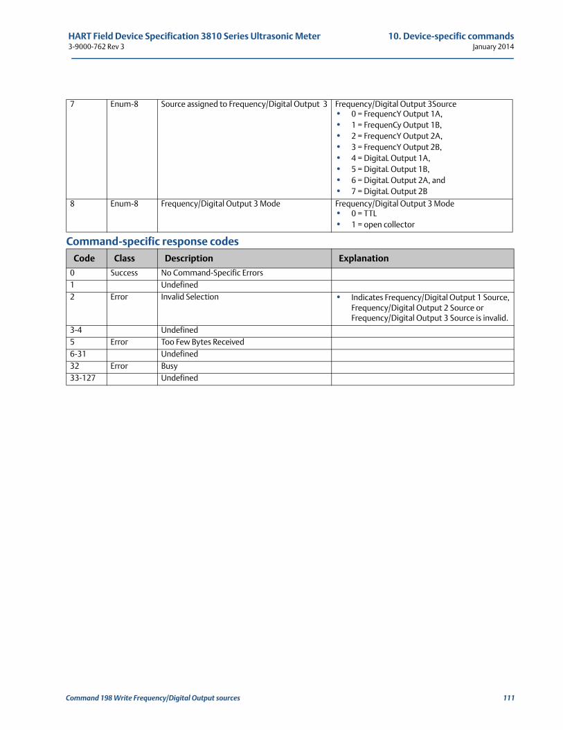
HART Field Device Specification 3810 Series Ultrasonic Meter 10. Device-specific commands3-9000-762 Rev 3 January 2014
Command-specific response codes
7 Enum-8 Source assigned to Frequency/Digital Output 3 Frequency/Digital Output 3Source• 0 = FrequencY Output 1A,• 1 = FrequenCy Output 1B,• 2 = FrequencY Output 2A,• 3 = FrequencY Output 2B,• 4 = DigitaL Output 1A,• 5 = DigitaL Output 1B,• 6 = DigitaL Output 2A, and• 7 = DigitaL Output 2B
8 Enum-8 Frequency/Digital Output 3 Mode Frequency/Digital Output 3 Mode• 0 = TTL• 1 = open collector
Code Class Description Explanation
0 Success No Command-Specific Errors1 Undefined2 Error Invalid Selection • Indicates Frequency/Digital Output 1 Source,
Frequency/Digital Output 2 Source or Frequency/Digital Output 3 Source is invalid.
3-4 Undefined5 Error Too Few Bytes Received6-31 Undefined32 Error Busy33-127 Undefined
Command 198 Write Frequency/Digital Output sources 111
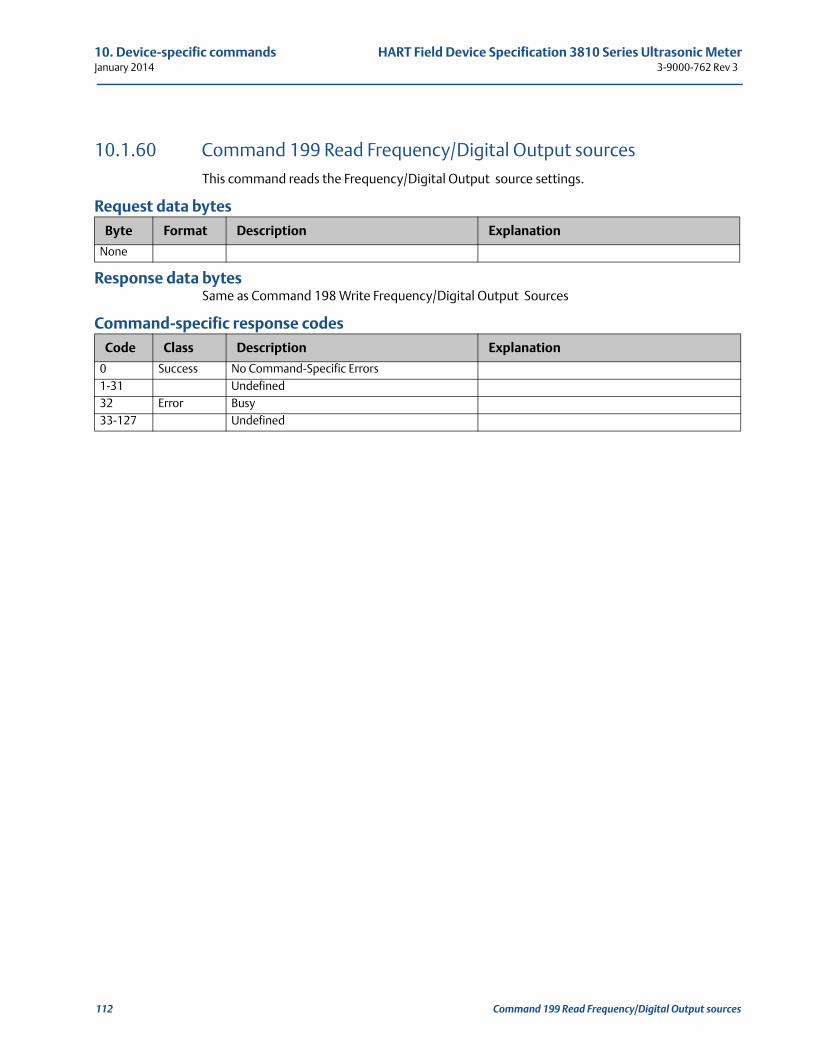
10. Device-specific commands HART Field Device Specification 3810 Series Ultrasonic MeterJanuary 2014 3-9000-762 Rev 3
10.1.60 Command 199 Read Frequency/Digital Output sources This command reads the Frequency/Digital Output source settings.
Request data bytes
Response data bytesSame as Command 198 Write Frequency/Digital Output Sources
Command-specific response codes
Byte Format Description Explanation
None
Code Class Description Explanation
0 Success No Command-Specific Errors1-31 Undefined32 Error Busy33-127 Undefined
112 Command 199 Read Frequency/Digital Output sources
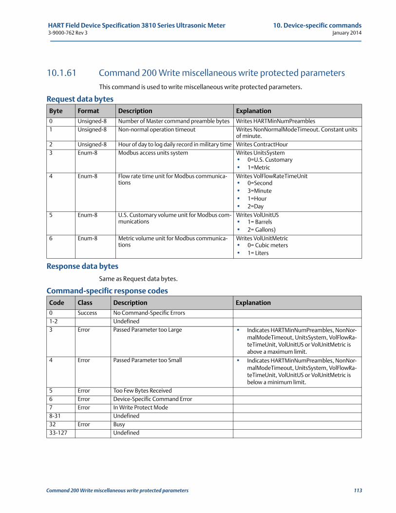
HART Field Device Specification 3810 Series Ultrasonic Meter 10. Device-specific commands3-9000-762 Rev 3 January 2014
10.1.61 Command 200 Write miscellaneous write protected parametersThis command is used to write miscellaneous write protected parameters.
Request data bytes
Response data bytes
Same as Request data bytes.
Command-specific response codes
Byte Format Description Explanation
0 Unsigned-8 Number of Master command preamble bytes Writes HARTMinNumPreambles1 Unsigned-8 Non-normal operation timeout Writes NonNormalModeTimeout. Constant units
of minute.2 Unsigned-8 Hour of day to log daily record in military time Writes ContractHour3 Enum-8 Modbus access units system Writes UnitsSystem
• 0=U.S. Customary• 1=Metric
4 Enum-8 Flow rate time unit for Modbus communica-tions
Writes VolFlowRateTimeUnit • 0=Second• 3=Minute• 1=Hour• 2=Day
5 Enum-8 U.S. Customary volume unit for Modbus com-munications
Writes VolUnitUS • 1= Barrels• 2= Gallons)
6 Enum-8 Metric volume unit for Modbus communica-tions
Writes VolUnitMetric • 0= Cubic meters• 1= Liters
Code Class Description Explanation
0 Success No Command-Specific Errors1-2 Undefined3 Error Passed Parameter too Large • Indicates HARTMinNumPreambles, NonNor-
malModeTimeout, UnitsSystem, VolFlowRa-teTimeUnit, VolUnitUS or VolUnitMetric is above a maximum limit.
4 Error Passed Parameter too Small • Indicates HARTMinNumPreambles, NonNor-malModeTimeout, UnitsSystem, VolFlowRa-teTimeUnit, VolUnitUS or VolUnitMetric is below a minimum limit.
5 Error Too Few Bytes Received6 Error Device-Specific Command Error7 Error In Write Protect Mode8-31 Undefined32 Error Busy33-127 Undefined
Command 200 Write miscellaneous write protected parameters 113
10. Device-specific commands HART Field Device Specification 3810 Series Ultrasonic MeterJanuary 2014 3-9000-762 Rev 3
114 Command 200 Write miscellaneous write protected parameters
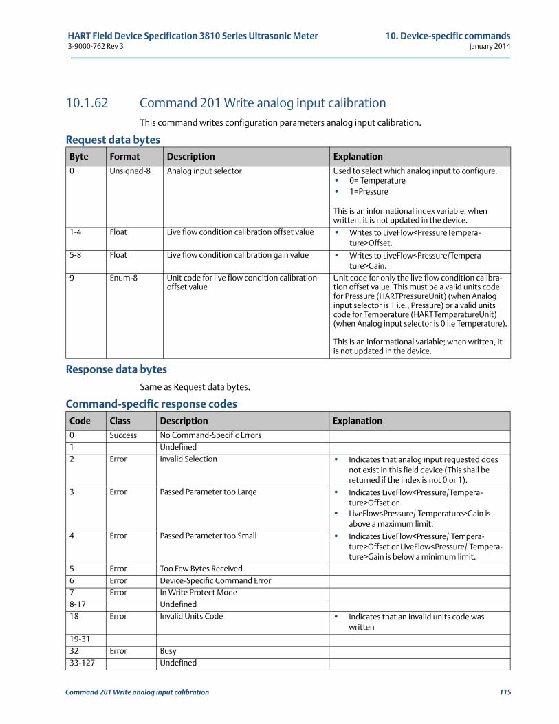
HART Field Device Specification 3810 Series Ultrasonic Meter 10. Device-specific commands3-9000-762 Rev 3 January 2014
10.1.62 Command 201 Write analog input calibrationThis command writes configuration parameters analog input calibration.
Request data bytes
Response data bytes
Same as Request data bytes.
Command-specific response codes
Byte Format Description Explanation
0 Unsigned-8 Analog input selector Used to select which analog input to configure.• 0= Temperature• 1=Pressure
This is an informational index variable; when written, it is not updated in the device.
1-4 Float Live flow condition calibration offset value • Writes to LiveFlow<PressureTempera-ture>Offset.
5-8 Float Live flow condition calibration gain value • Writes to LiveFlow<Pressure/Tempera-ture>Gain.
9 Enum-8 Unit code for live flow condition calibration offset value
Unit code for only the live flow condition calibra-tion offset value. This must be a valid units code for Pressure (HARTPressureUnit) (when Analog input selector is 1 i.e., Pressure) or a valid units code for Temperature (HARTTemperatureUnit) (when Analog input selector is 0 i.e Temperature).
This is an informational variable; when written, it is not updated in the device.
Code Class Description Explanation
0 Success No Command-Specific Errors1 Undefined2 Error Invalid Selection • Indicates that analog input requested does
not exist in this field device (This shall be returned if the index is not 0 or 1).
3 Error Passed Parameter too Large • Indicates LiveFlow<Pressure/Tempera-ture>Offset or
• LiveFlow<Pressure/ Temperature>Gain is above a maximum limit.
4 Error Passed Parameter too Small • Indicates LiveFlow<Pressure/ Tempera-ture>Offset or LiveFlow<Pressure/ Tempera-ture>Gain is below a minimum limit.
5 Error Too Few Bytes Received6 Error Device-Specific Command Error7 Error In Write Protect Mode8-17 Undefined18 Error Invalid Units Code • Indicates that an invalid units code was
written19-3132 Error Busy33-127 Undefined
Command 201 Write analog input calibration 115
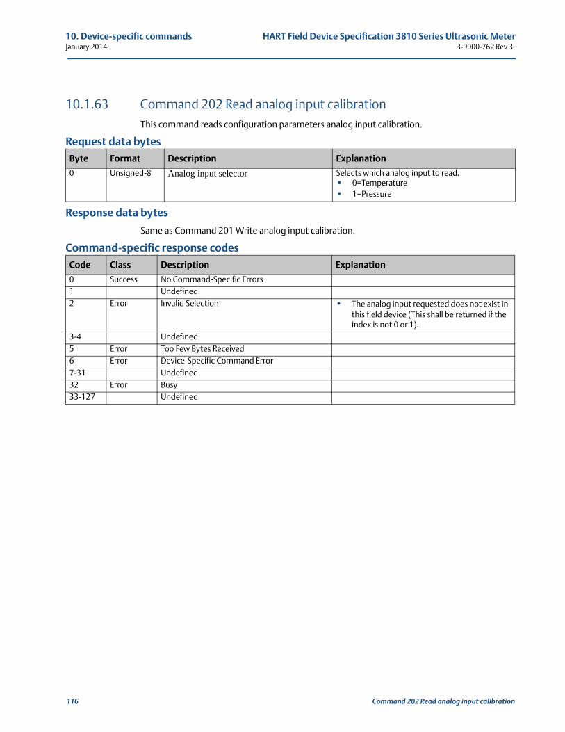
10. Device-specific commands HART Field Device Specification 3810 Series Ultrasonic MeterJanuary 2014 3-9000-762 Rev 3
10.1.63 Command 202 Read analog input calibrationThis command reads configuration parameters analog input calibration.
Request data bytes
Response data bytes
Same as Command 201 Write analog input calibration.
Command-specific response codes
Byte Format Description Explanation
0 Unsigned-8 Analog input selector Selects which analog input to read.• 0=Temperature• 1=Pressure
Code Class Description Explanation
0 Success No Command-Specific Errors1 Undefined2 Error Invalid Selection • The analog input requested does not exist in
this field device (This shall be returned if the index is not 0 or 1).
3-4 Undefined5 Error Too Few Bytes Received6 Error Device-Specific Command Error7-31 Undefined32 Error Busy33-127 Undefined
116 Command 202 Read analog input calibration
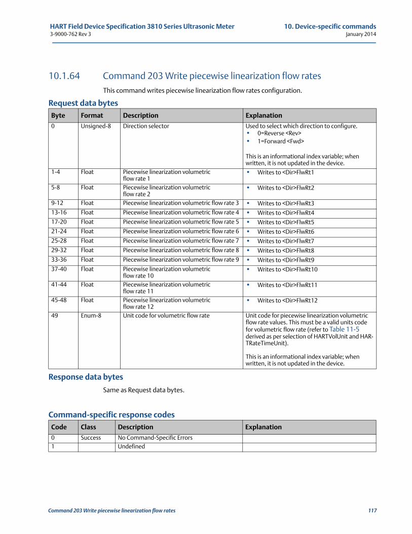
HART Field Device Specification 3810 Series Ultrasonic Meter 10. Device-specific commands3-9000-762 Rev 3 January 2014
10.1.64 Command 203 Write piecewise linearization flow ratesThis command writes piecewise linearization flow rates configuration.
Request data bytes
Response data bytes
Same as Request data bytes.
Command-specific response codes
Byte Format Description Explanation
0 Unsigned-8 Direction selector Used to select which direction to configure.• 0=Reverse <Rev> • 1=Forward <Fwd>
This is an informational index variable; when written, it is not updated in the device.
1-4 Float Piecewise linearization volumetric flow rate 1
• Writes to <Dir>FlwRt1
5-8 Float Piecewise linearization volumetric flow rate 2
• Writes to <Dir>FlwRt2
9-12 Float Piecewise linearization volumetric flow rate 3 • Writes to <Dir>FlwRt3
13-16 Float Piecewise linearization volumetric flow rate 4 • Writes to <Dir>FlwRt4
17-20 Float Piecewise linearization volumetric flow rate 5 • Writes to <Dir>FlwRt5
21-24 Float Piecewise linearization volumetric flow rate 6 • Writes to <Dir>FlwRt6
25-28 Float Piecewise linearization volumetric flow rate 7 • Writes to <Dir>FlwRt7
29-32 Float Piecewise linearization volumetric flow rate 8 • Writes to <Dir>FlwRt8
33-36 Float Piecewise linearization volumetric flow rate 9 • Writes to <Dir>FlwRt9
37-40 Float Piecewise linearization volumetric flow rate 10
• Writes to <Dir>FlwRt10
41-44 Float Piecewise linearization volumetric flow rate 11
• Writes to <Dir>FlwRt11
45-48 Float Piecewise linearization volumetric flow rate 12
• Writes to <Dir>FlwRt12
49 Enum-8 Unit code for volumetric flow rate Unit code for piecewise linearization volumetric flow rate values. This must be a valid units code for volumetric flow rate (refer to Table 11-5 derived as per selection of HARTVolUnit and HAR-TRateTimeUnit).
This is an informational index variable; when written, it is not updated in the device.
Code Class Description Explanation
0 Success No Command-Specific Errors1 Undefined
Command 203 Write piecewise linearization flow rates 117
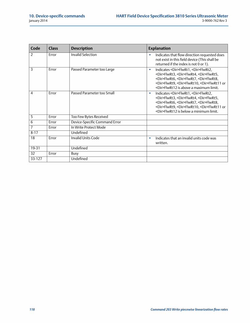
10. Device-specific commands HART Field Device Specification 3810 Series Ultrasonic MeterJanuary 2014 3-9000-762 Rev 3
2 Error Invalid Selection • Indicates that flow direction requested does not exist in this field device (This shall be returned if the index is not 0 or 1).
3 Error Passed Parameter too Large • Indicates <Dir>FlwRt1, <Dir>FlwRt2, <Dir>FlwRt3, <Dir>FlwRt4, <Dir>FlwRt5, <Dir>FlwRt6, <Dir>FlwRt7, <Dir>FlwRt8, <Dir>FlwRt9, <Dir>FlwRt10, <Dir>FlwRt11 or <Dir>FlwRt12 is above a maximum limit.
4 Error Passed Parameter too Small • Indicates <Dir>FlwRt1, <Dir>FlwRt2, <Dir>FlwRt3, <Dir>FlwRt4, <Dir>FlwRt5, <Dir>FlwRt6, <Dir>FlwRt7, <Dir>FlwRt8, <Dir>FlwRt9, <Dir>FlwRt10, <Dir>FlwRt11 or <Dir>FlwRt12 is below a minimum limit.
5 Error Too Few Bytes Received6 Error Device-Specific Command Error7 Error In Write Protect Mode8-17 Undefined18 Error Invalid Units Code • Indicates that an invalid units code was
written.19-31 Undefined32 Error Busy33-127 Undefined
Code Class Description Explanation
118 Command 203 Write piecewise linearization flow rates
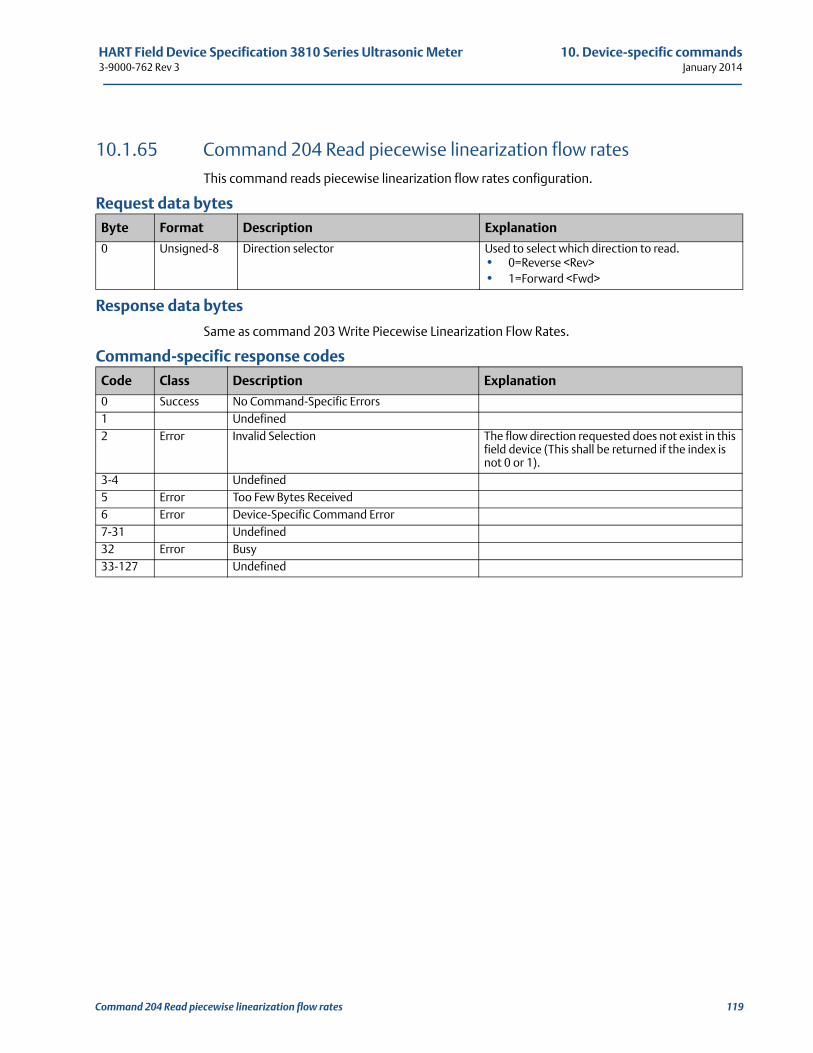
HART Field Device Specification 3810 Series Ultrasonic Meter 10. Device-specific commands3-9000-762 Rev 3 January 2014
10.1.65 Command 204 Read piecewise linearization flow ratesThis command reads piecewise linearization flow rates configuration.
Request data bytes
Response data bytes
Same as command 203 Write Piecewise Linearization Flow Rates.
Command-specific response codes
Byte Format Description Explanation
0 Unsigned-8 Direction selector Used to select which direction to read.• 0=Reverse <Rev>• 1=Forward <Fwd>
Code Class Description Explanation
0 Success No Command-Specific Errors1 Undefined2 Error Invalid Selection The flow direction requested does not exist in this
field device (This shall be returned if the index is not 0 or 1).
3-4 Undefined5 Error Too Few Bytes Received6 Error Device-Specific Command Error7-31 Undefined32 Error Busy33-127 Undefined
Command 204 Read piecewise linearization flow rates 119
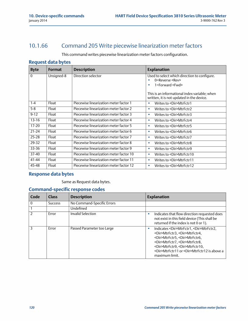
10. Device-specific commands HART Field Device Specification 3810 Series Ultrasonic MeterJanuary 2014 3-9000-762 Rev 3
10.1.66 Command 205 Write piecewise linearization meter factorsThis command writes piecewise linearization meter factors configuration.
Request data bytes
Response data bytes
Same as Request data bytes.
Command-specific response codes
Byte Format Description Explanation
0 Unsigned-8 Direction selector Used to select which direction to configure.• 0=Reverse <Rev>• 1=Forward <Fwd>
This is an informational index variable; when written, it is not updated in the device.
1-4 Float Piecewise linearization meter factor 1 • Writes to <Dir>MtrFctr1
5-8 Float Piecewise linearization meter factor 2 • Writes to <Dir>MtrFctr2
9-12 Float Piecewise linearization meter factor 3 • Writes to <Dir>MtrFctr3
13-16 Float Piecewise linearization meter factor 4 • Writes to <Dir>MtrFctr4
17-20 Float Piecewise linearization meter factor 5 • Writes to <Dir>MtrFctr5
21-24 Float Piecewise linearization meter factor 6 • Writes to <Dir>MtrFctr6
25-28 Float Piecewise linearization meter factor 7 • Writes to <Dir>MtrFctr7
29-32 Float Piecewise linearization meter factor 8 • Writes to <Dir>MtrFctr8
33-36 Float Piecewise linearization meter factor 9 • Writes to <Dir>MtrFctr9
37-40 Float Piecewise linearization meter factor 10 • Writes to <Dir>MtrFctr10
41-44 Float Piecewise linearization meter factor 11 • Writes to <Dir>MtrFctr11
45-48 Float Piecewise linearization meter factor 12 • Writes to <Dir>MtrFctr12
Code Class Description Explanation
0 Success No Command-Specific Errors1 Undefined2 Error Invalid Selection • Indicates that flow direction requested does
not exist in this field device (This shall be returned if the index is not 0 or 1).
3 Error Passed Parameter too Large • Indicates <Dir>MtrFctr1, <Dir>MtrFctr2, <Dir>MtrFctr3, <Dir>MtrFctr4, <Dir>MtrFctr5, <Dir>MtrFctr6, <Dir>MtrFctr7, <Dir>MtrFctr8, <Dir>MtrFctr9, <Dir>MtrFctr10, <Dir>MtrFctr11 or <Dir>MtrFctr12 is above a maximum limit.
120 Command 205 Write piecewise linearization meter factors
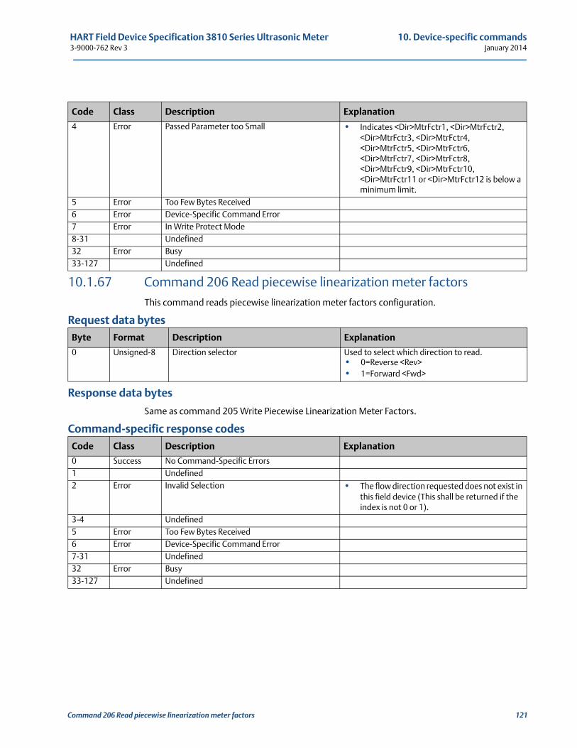
HART Field Device Specification 3810 Series Ultrasonic Meter 10. Device-specific commands3-9000-762 Rev 3 January 2014
10.1.67 Command 206 Read piecewise linearization meter factorsThis command reads piecewise linearization meter factors configuration.
Request data bytes
Response data bytes
Same as command 205 Write Piecewise Linearization Meter Factors.
Command-specific response codes
4 Error Passed Parameter too Small • Indicates <Dir>MtrFctr1, <Dir>MtrFctr2, <Dir>MtrFctr3, <Dir>MtrFctr4, <Dir>MtrFctr5, <Dir>MtrFctr6, <Dir>MtrFctr7, <Dir>MtrFctr8, <Dir>MtrFctr9, <Dir>MtrFctr10, <Dir>MtrFctr11 or <Dir>MtrFctr12 is below a minimum limit.
5 Error Too Few Bytes Received6 Error Device-Specific Command Error7 Error In Write Protect Mode8-31 Undefined32 Error Busy33-127 Undefined
Byte Format Description Explanation
0 Unsigned-8 Direction selector Used to select which direction to read.• 0=Reverse <Rev>• 1=Forward <Fwd>
Code Class Description Explanation
0 Success No Command-Specific Errors1 Undefined2 Error Invalid Selection • The flow direction requested does not exist in
this field device (This shall be returned if the index is not 0 or 1).
3-4 Undefined5 Error Too Few Bytes Received6 Error Device-Specific Command Error7-31 Undefined32 Error Busy33-127 Undefined
Code Class Description Explanation
Command 206 Read piecewise linearization meter factors 121
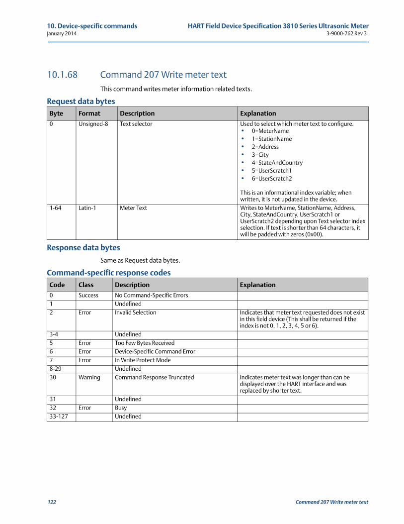
10. Device-specific commands HART Field Device Specification 3810 Series Ultrasonic MeterJanuary 2014 3-9000-762 Rev 3
10.1.68 Command 207 Write meter textThis command writes meter information related texts.
Request data bytes
Response data bytes
Same as Request data bytes.
Command-specific response codes
Byte Format Description Explanation
0 Unsigned-8 Text selector Used to select which meter text to configure.• 0=MeterName• 1=StationName• 2=Address• 3=City• 4=StateAndCountry• 5=UserScratch1• 6=UserScratch2
This is an informational index variable; when written, it is not updated in the device.
1-64 Latin-1 Meter Text Writes to MeterName, StationName, Address, City, StateAndCountry, UserScratch1 or UserScratch2 depending upon Text selector index selection. If text is shorter than 64 characters, it will be padded with zeros (0x00).
Code Class Description Explanation
0 Success No Command-Specific Errors1 Undefined2 Error Invalid Selection Indicates that meter text requested does not exist
in this field device (This shall be returned if the index is not 0, 1, 2, 3, 4, 5 or 6).
3-4 Undefined5 Error Too Few Bytes Received6 Error Device-Specific Command Error7 Error In Write Protect Mode8-29 Undefined30 Warning Command Response Truncated Indicates meter text was longer than can be
displayed over the HART interface and was replaced by shorter text.
31 Undefined32 Error Busy33-127 Undefined
122 Command 207 Write meter text
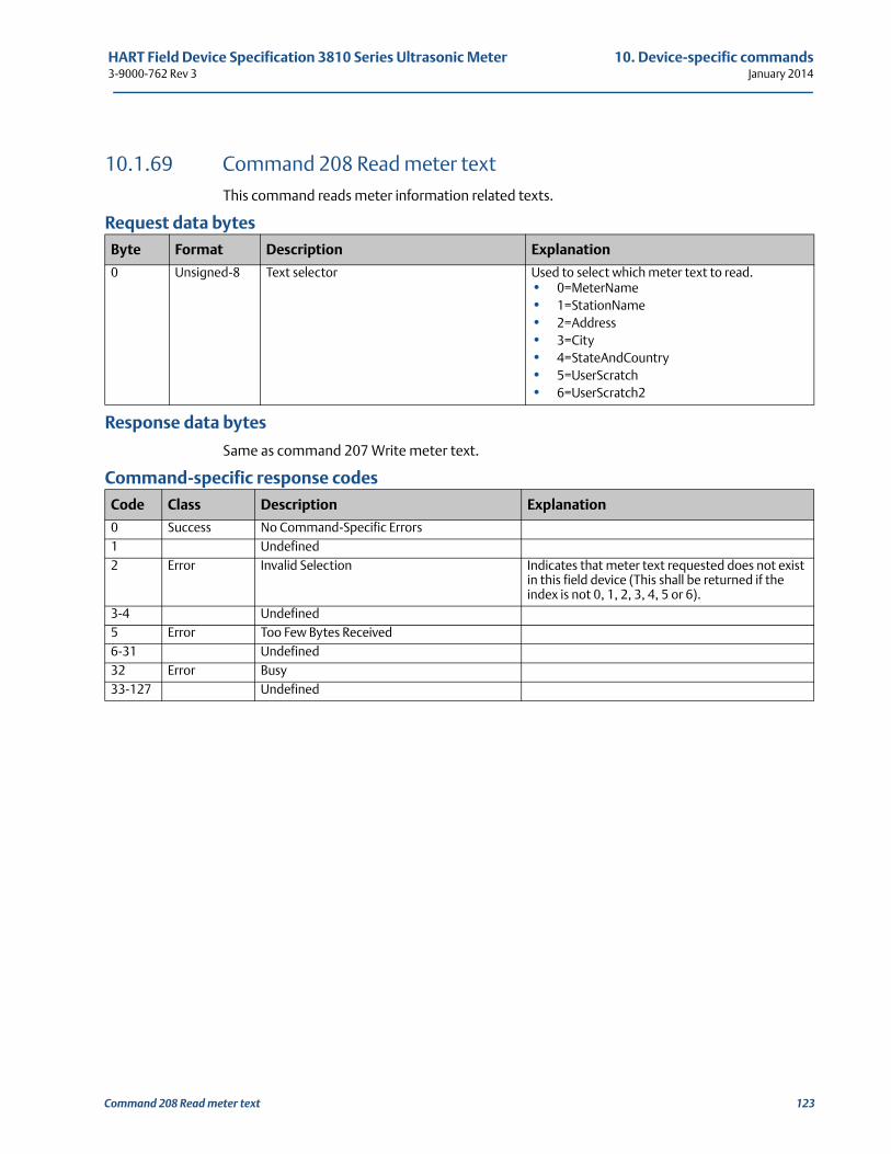
HART Field Device Specification 3810 Series Ultrasonic Meter 10. Device-specific commands3-9000-762 Rev 3 January 2014
10.1.69 Command 208 Read meter textThis command reads meter information related texts.
Request data bytes
Response data bytes
Same as command 207 Write meter text.
Command-specific response codes
Byte Format Description Explanation
0 Unsigned-8 Text selector Used to select which meter text to read.• 0=MeterName• 1=StationName• 2=Address• 3=City• 4=StateAndCountry• 5=UserScratch• 6=UserScratch2
Code Class Description Explanation
0 Success No Command-Specific Errors1 Undefined2 Error Invalid Selection Indicates that meter text requested does not exist
in this field device (This shall be returned if the index is not 0, 1, 2, 3, 4, 5 or 6).
3-4 Undefined5 Error Too Few Bytes Received6-31 Undefined32 Error Busy33-127 Undefined
Command 208 Read meter text 123
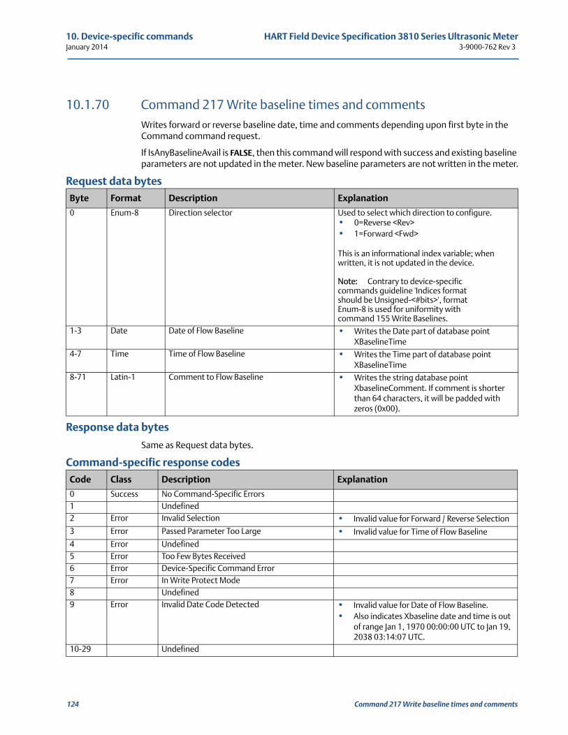
10. Device-specific commands HART Field Device Specification 3810 Series Ultrasonic MeterJanuary 2014 3-9000-762 Rev 3
124 Command 217 Write baseline times and comments
10.1.70 Command 217 Write baseline times and commentsWrites forward or reverse baseline date, time and comments depending upon first byte in the Command command request.
If IsAnyBaselineAvail is FALSE, then this command will respond with success and existing baseline parameters are not updated in the meter. New baseline parameters are not written in the meter.
Request data bytes
Response data bytes
Same as Request data bytes.
Command-specific response codes
Byte Format Description Explanation
0 Enum-8 Direction selector Used to select which direction to configure.• 0=Reverse <Rev>• 1=Forward <Fwd>
This is an informational index variable; when written, it is not updated in the device.
Note: Contrary to device-specific commands guideline 'Indices format should be Unsigned-<#bits>', format Enum-8 is used for uniformity with command 155 Write Baselines.
1-3 Date Date of Flow Baseline • Writes the Date part of database point XBaselineTime
4-7 Time Time of Flow Baseline • Writes the Time part of database pointXBaselineTime
8-71 Latin-1 Comment to Flow Baseline • Writes the string database point XbaselineComment. If comment is shorter than 64 characters, it will be padded with zeros (0x00).
Code Class Description Explanation
0 Success No Command-Specific Errors1 Undefined2 Error Invalid Selection • Invalid value for Forward / Reverse Selection
3 Error Passed Parameter Too Large • Invalid value for Time of Flow Baseline
4 Error Undefined5 Error Too Few Bytes Received6 Error Device-Specific Command Error7 Error In Write Protect Mode8 Undefined9 Error Invalid Date Code Detected • Invalid value for Date of Flow Baseline.
• Also indicates Xbaseline date and time is out of range Jan 1, 1970 00:00:00 UTC to Jan 19, 2038 03:14:07 UTC.
10-29 Undefined
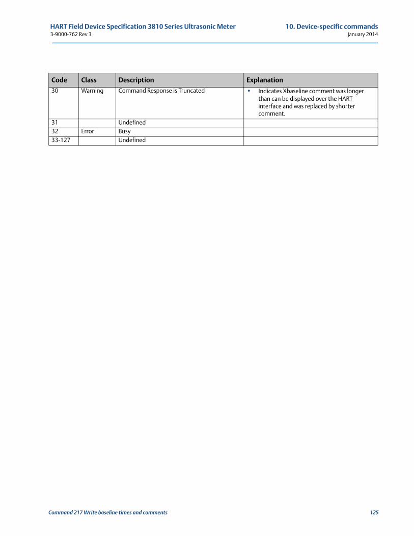
HART Field Device Specification 3810 Series Ultrasonic Meter 10. Device-specific commands3-9000-762 Rev 3 January 2014
30 Warning Command Response is Truncated • Indicates Xbaseline comment was longer than can be displayed over the HART interface and was replaced by shorter comment.
31 Undefined32 Error Busy33-127 Undefined
Code Class Description Explanation
Command 217 Write baseline times and comments 125
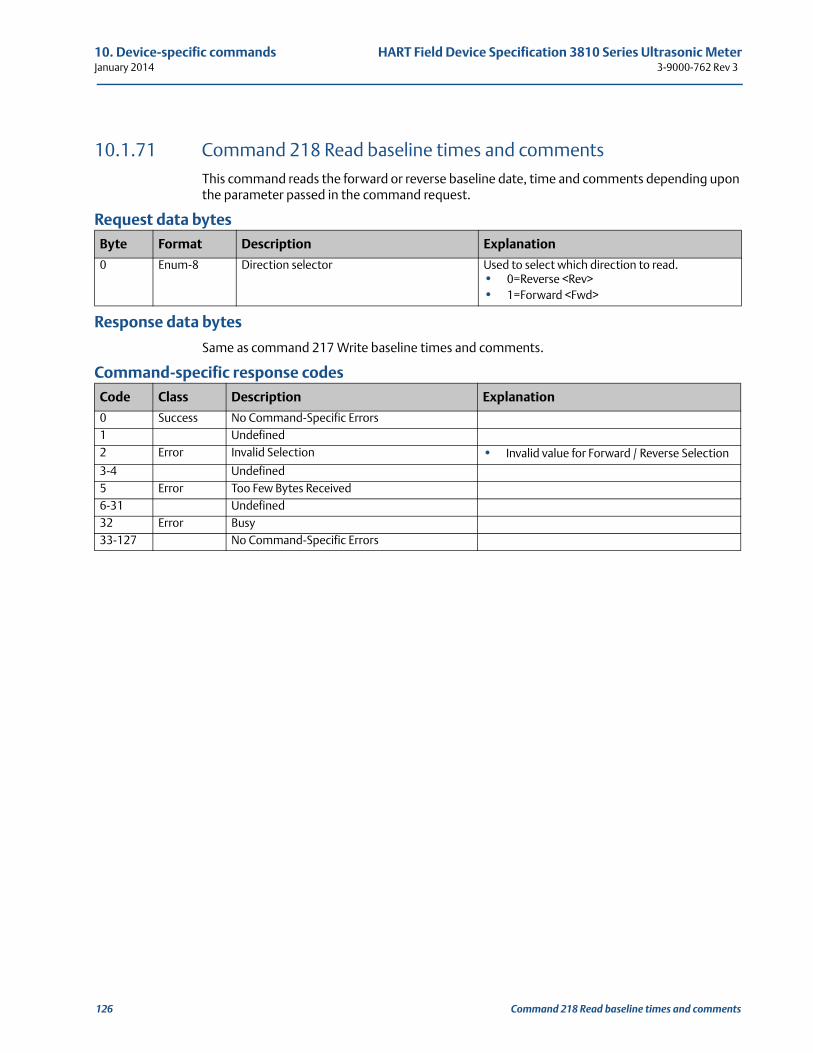
10. Device-specific commands HART Field Device Specification 3810 Series Ultrasonic MeterJanuary 2014 3-9000-762 Rev 3
10.1.71 Command 218 Read baseline times and commentsThis command reads the forward or reverse baseline date, time and comments depending upon the parameter passed in the command request.
Request data bytes
Response data bytes
Same as command 217 Write baseline times and comments.
Command-specific response codes
Byte Format Description Explanation
0 Enum-8 Direction selector Used to select which direction to read.• 0=Reverse <Rev> • 1=Forward <Fwd>
Code Class Description Explanation
0 Success No Command-Specific Errors1 Undefined2 Error Invalid Selection • Invalid value for Forward / Reverse Selection
3-4 Undefined5 Error Too Few Bytes Received6-31 Undefined32 Error Busy33-127 No Command-Specific Errors
126 Command 218 Read baseline times and comments
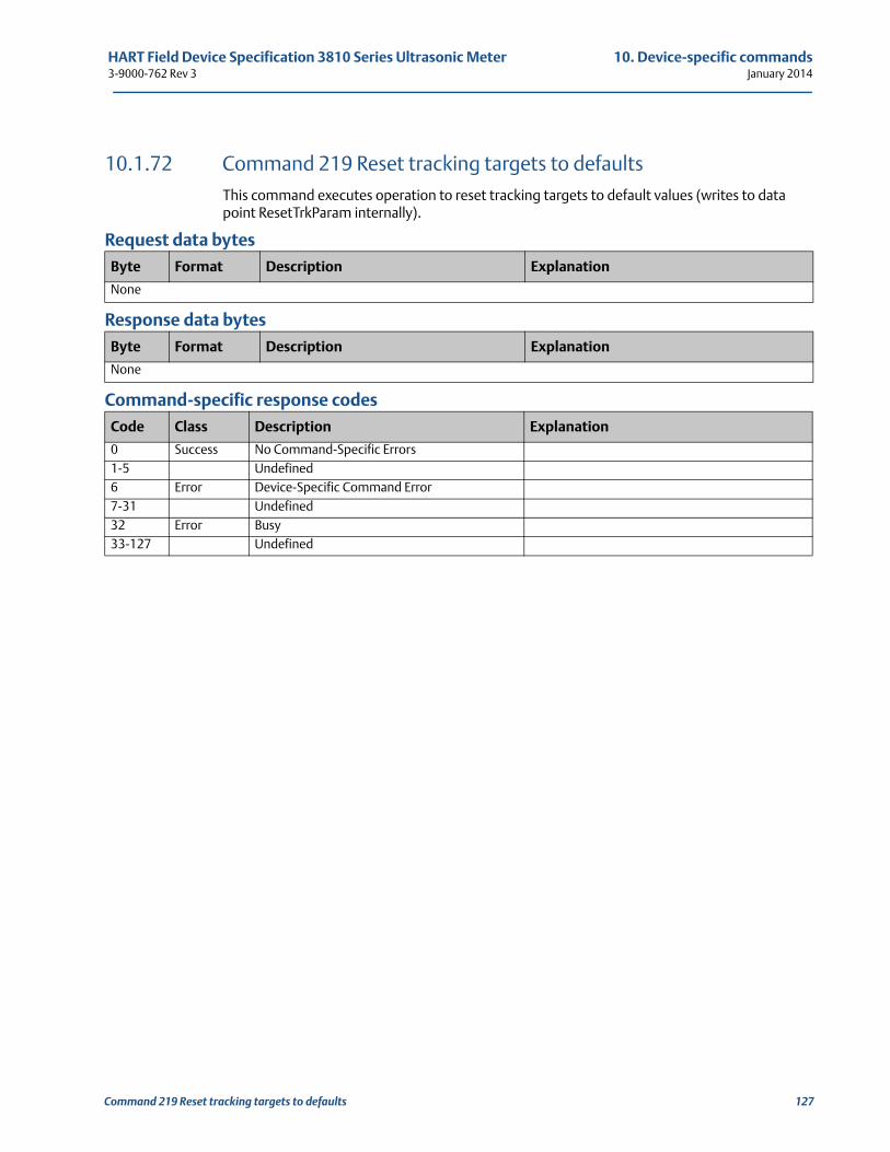
HART Field Device Specification 3810 Series Ultrasonic Meter 10. Device-specific commands3-9000-762 Rev 3 January 2014
10.1.72 Command 219 Reset tracking targets to defaultsThis command executes operation to reset tracking targets to default values (writes to data point ResetTrkParam internally).
Request data bytes
Response data bytes
Command-specific response codes
Byte Format Description Explanation
None
Byte Format Description Explanation
None
Code Class Description Explanation
0 Success No Command-Specific Errors1-5 Undefined6 Error Device-Specific Command Error7-31 Undefined32 Error Busy33-127 Undefined
Command 219 Reset tracking targets to defaults 127
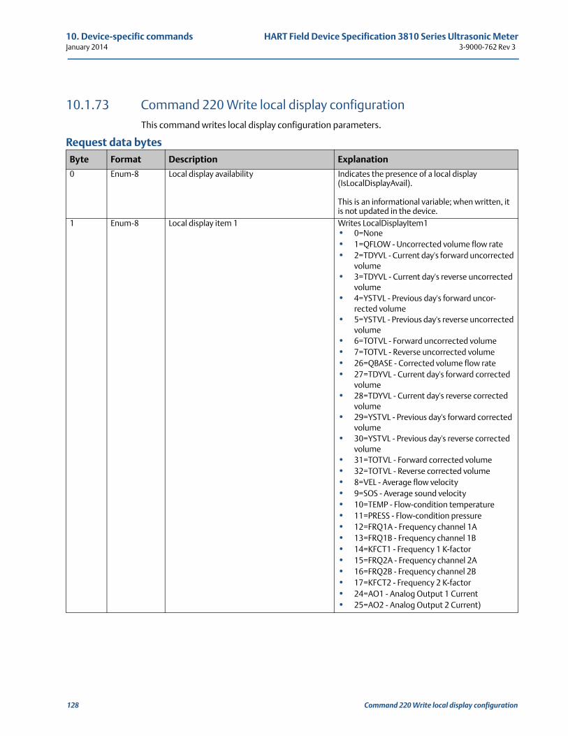
10. Device-specific commands HART Field Device Specification 3810 Series Ultrasonic MeterJanuary 2014 3-9000-762 Rev 3
10.1.73 Command 220 Write local display configurationThis command writes local display configuration parameters.
Request data bytes
Byte Format Description Explanation
0 Enum-8 Local display availability Indicates the presence of a local display (IsLocalDisplayAvail).
This is an informational variable; when written, it is not updated in the device.
1 Enum-8 Local display item 1 Writes LocalDisplayItem1• 0=None• 1=QFLOW - Uncorrected volume flow rate• 2=TDYVL - Current day's forward uncorrected
volume• 3=TDYVL - Current day's reverse uncorrected
volume• 4=YSTVL - Previous day's forward uncor-
rected volume• 5=YSTVL - Previous day's reverse uncorrected
volume• 6=TOTVL - Forward uncorrected volume• 7=TOTVL - Reverse uncorrected volume• 26=QBASE - Corrected volume flow rate• 27=TDYVL - Current day's forward corrected
volume• 28=TDYVL - Current day's reverse corrected
volume• 29=YSTVL - Previous day's forward corrected
volume• 30=YSTVL - Previous day's reverse corrected
volume• 31=TOTVL - Forward corrected volume• 32=TOTVL - Reverse corrected volume• 8=VEL - Average flow velocity• 9=SOS - Average sound velocity• 10=TEMP - Flow-condition temperature• 11=PRESS - Flow-condition pressure• 12=FRQ1A - Frequency channel 1A• 13=FRQ1B - Frequency channel 1B• 14=KFCT1 - Frequency 1 K-factor• 15=FRQ2A - Frequency channel 2A• 16=FRQ2B - Frequency channel 2B• 17=KFCT2 - Frequency 2 K-factor• 24=AO1 - Analog Output 1 Current• 25=AO2 - Analog Output 2 Current)
128 Command 220 Write local display configuration
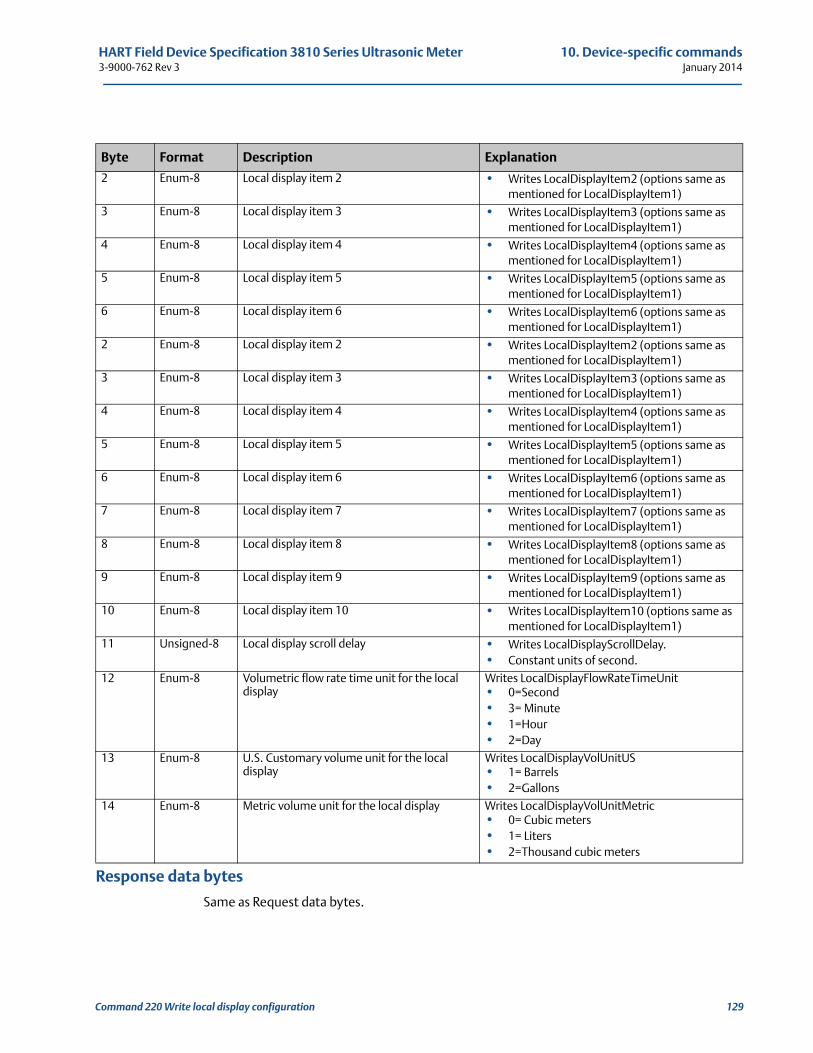
HART Field Device Specification 3810 Series Ultrasonic Meter 10. Device-specific commands3-9000-762 Rev 3 January 2014
Response data bytes
Same as Request data bytes.
2 Enum-8 Local display item 2 • Writes LocalDisplayItem2 (options same as mentioned for LocalDisplayItem1)
3 Enum-8 Local display item 3 • Writes LocalDisplayItem3 (options same as mentioned for LocalDisplayItem1)
4 Enum-8 Local display item 4 • Writes LocalDisplayItem4 (options same as mentioned for LocalDisplayItem1)
5 Enum-8 Local display item 5 • Writes LocalDisplayItem5 (options same as mentioned for LocalDisplayItem1)
6 Enum-8 Local display item 6 • Writes LocalDisplayItem6 (options same as mentioned for LocalDisplayItem1)
7 Enum-8 Local display item 7 • Writes LocalDisplayItem7 (options same as mentioned for LocalDisplayItem1)
8 Enum-8 Local display item 8 • Writes LocalDisplayItem8 (options same as mentioned for LocalDisplayItem1)
9 Enum-8 Local display item 9 • Writes LocalDisplayItem9 (options same as mentioned for LocalDisplayItem1)
10 Enum-8 Local display item 10 • Writes LocalDisplayItem10 (options same as mentioned for LocalDisplayItem1)
11 Unsigned-8 Local display scroll delay • Writes LocalDisplayScrollDelay.• Constant units of second.
12 Enum-8 Volumetric flow rate time unit for the local display
Writes LocalDisplayFlowRateTimeUnit• 0=Second• 3= Minute• 1=Hour• 2=Day
13 Enum-8 U.S. Customary volume unit for the local display
Writes LocalDisplayVolUnitUS• 1= Barrels• 2=Gallons
14 Enum-8 Metric volume unit for the local display Writes LocalDisplayVolUnitMetric • 0= Cubic meters • 1= Liters• 2=Thousand cubic meters
Byte Format Description Explanation
Command 220 Write local display configuration 129
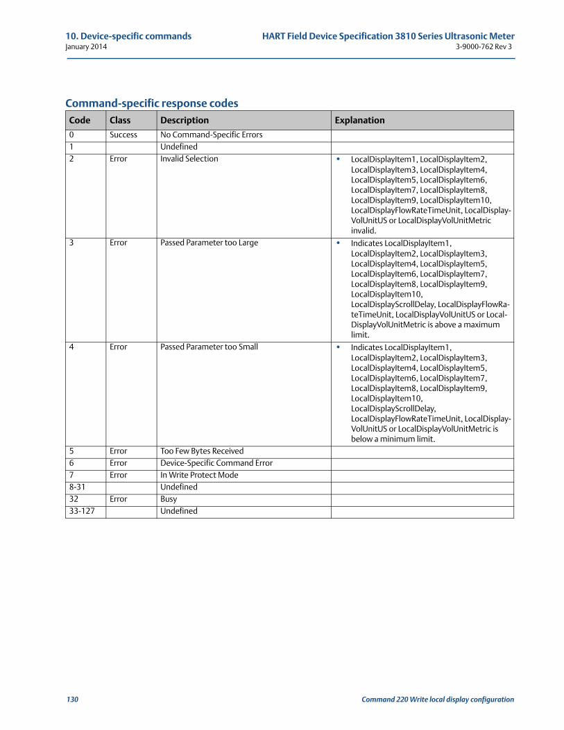
10. Device-specific commands HART Field Device Specification 3810 Series Ultrasonic MeterJanuary 2014 3-9000-762 Rev 3
Command-specific response codes
Code Class Description Explanation
0 Success No Command-Specific Errors1 Undefined2 Error Invalid Selection • LocalDisplayItem1, LocalDisplayItem2,
LocalDisplayItem3, LocalDisplayItem4, LocalDisplayItem5, LocalDisplayItem6, LocalDisplayItem7, LocalDisplayItem8, LocalDisplayItem9, LocalDisplayItem10, LocalDisplayFlowRateTimeUnit, LocalDisplay-VolUnitUS or LocalDisplayVolUnitMetric invalid.
3 Error Passed Parameter too Large • Indicates LocalDisplayItem1, LocalDisplayItem2, LocalDisplayItem3, LocalDisplayItem4, LocalDisplayItem5, LocalDisplayItem6, LocalDisplayItem7, LocalDisplayItem8, LocalDisplayItem9, LocalDisplayItem10, LocalDisplayScrollDelay, LocalDisplayFlowRa-teTimeUnit, LocalDisplayVolUnitUS or Local-DisplayVolUnitMetric is above a maximum limit.
4 Error Passed Parameter too Small • Indicates LocalDisplayItem1, LocalDisplayItem2, LocalDisplayItem3, LocalDisplayItem4, LocalDisplayItem5, LocalDisplayItem6, LocalDisplayItem7, LocalDisplayItem8, LocalDisplayItem9, LocalDisplayItem10, LocalDisplayScrollDelay, LocalDisplayFlowRateTimeUnit, LocalDisplay-VolUnitUS or LocalDisplayVolUnitMetric is below a minimum limit.
5 Error Too Few Bytes Received6 Error Device-Specific Command Error7 Error In Write Protect Mode8-31 Undefined32 Error Busy33-127 Undefined
130 Command 220 Write local display configuration
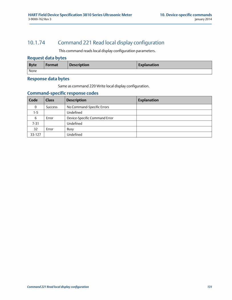
HART Field Device Specification 3810 Series Ultrasonic Meter 10. Device-specific commands3-9000-762 Rev 3 January 2014
10.1.74 Command 221 Read local display configuration This command reads local display configuration parameters.
Request data bytes
Response data bytes
Same as command 220 Write local display configuration.
Command-specific response codes
Byte Format Description Explanation
None
Code Class Description Explanation
0 Success No Command-Specific Errors
1-5 Undefined
6 Error Device-Specific Command Error
7-31 Undefined
32 Error Busy
33-127 Undefined
Command 221 Read local display configuration 131
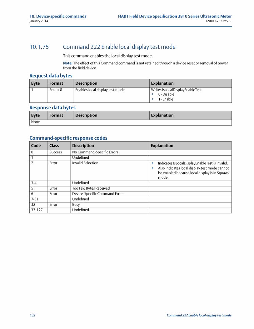
10. Device-specific commands HART Field Device Specification 3810 Series Ultrasonic MeterJanuary 2014 3-9000-762 Rev 3
10.1.75 Command 222 Enable local display test modeThis command enables the local display test mode.
Note: The effect of this Command command is not retained through a device reset or removal of power from the field device.
Request data bytes
Response data bytes
Command-specific response codes
Byte Format Description Explanation
1 Enum-8 Enables local display test mode Writes IsLocalDisplayEnableTest• 0=Disable• 1=Enable
Byte Format Description Explanation
None
Code Class Description Explanation
0 Success No Command-Specific Errors1 Undefined2 Error Invalid Selection • Indicates IsLocalDisplayEnableTest is invalid.
• Also indicates local display test mode cannot be enabled because local display is in Squawk mode.
3-4 Undefined5 Error Too Few Bytes Received6 Error Device-Specific Command Error7-31 Undefined32 Error Busy33-127 Undefined
132 Command 222 Enable local display test mode
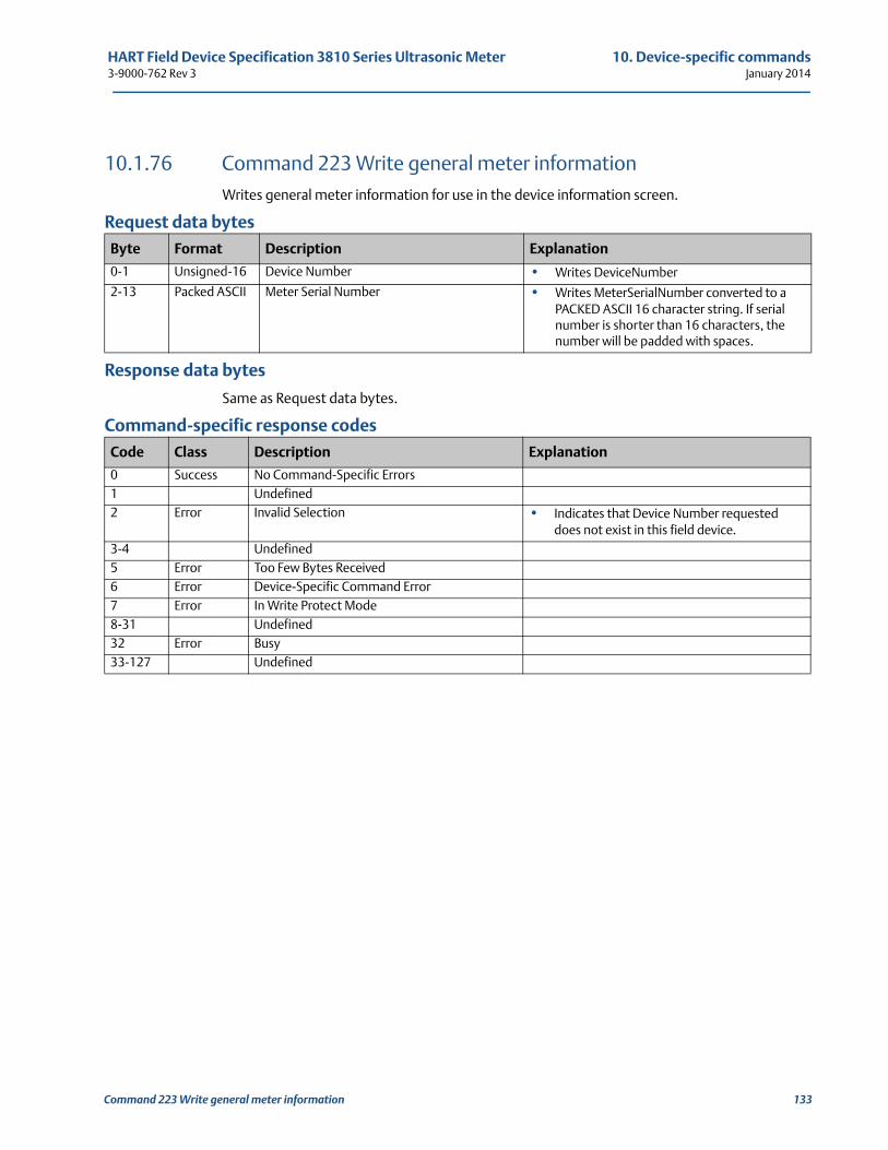
HART Field Device Specification 3810 Series Ultrasonic Meter 10. Device-specific commands3-9000-762 Rev 3 January 2014
10.1.76 Command 223 Write general meter informationWrites general meter information for use in the device information screen.
Request data bytes
Response data bytes
Same as Request data bytes.
Command-specific response codes
Byte Format Description Explanation
0-1 Unsigned-16 Device Number • Writes DeviceNumber
2-13 Packed ASCII Meter Serial Number • Writes MeterSerialNumber converted to a PACKED ASCII 16 character string. If serial number is shorter than 16 characters, the number will be padded with spaces.
Code Class Description Explanation
0 Success No Command-Specific Errors1 Undefined2 Error Invalid Selection • Indicates that Device Number requested
does not exist in this field device.3-4 Undefined5 Error Too Few Bytes Received6 Error Device-Specific Command Error7 Error In Write Protect Mode8-31 Undefined32 Error Busy33-127 Undefined
Command 223 Write general meter information 133
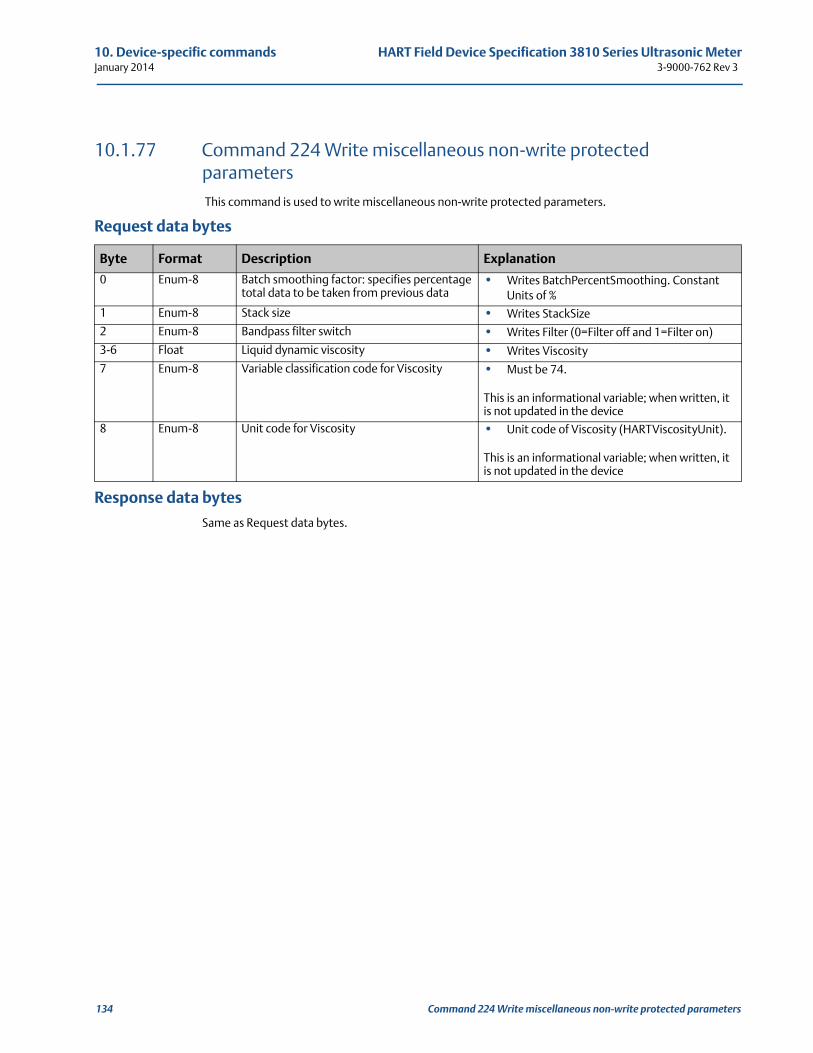
10. Device-specific commands HART Field Device Specification 3810 Series Ultrasonic MeterJanuary 2014 3-9000-762 Rev 3
10.1.77 Command 224 Write miscellaneous non-write protected parameters This command is used to write miscellaneous non-write protected parameters.
Request data bytes
Response data bytes
Same as Request data bytes.
Byte Format Description Explanation
0 Enum-8 Batch smoothing factor: specifies percentage total data to be taken from previous data
• Writes BatchPercentSmoothing. Constant Units of %
1 Enum-8 Stack size • Writes StackSize
2 Enum-8 Bandpass filter switch • Writes Filter (0=Filter off and 1=Filter on)
3-6 Float Liquid dynamic viscosity • Writes Viscosity
7 Enum-8 Variable classification code for Viscosity • Must be 74.
This is an informational variable; when written, it is not updated in the device
8 Enum-8 Unit code for Viscosity • Unit code of Viscosity (HARTViscosityUnit).
This is an informational variable; when written, it is not updated in the device
134 Command 224 Write miscellaneous non-write protected parameters
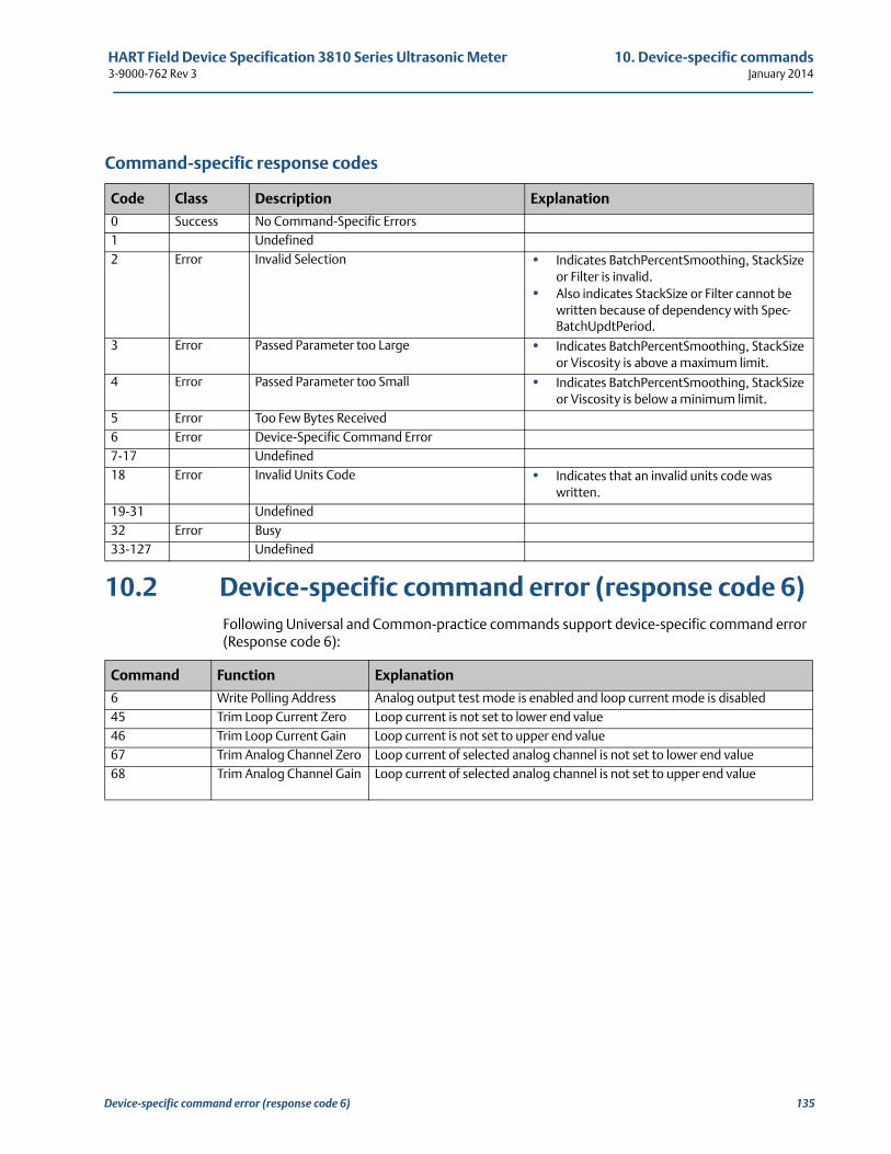
HART Field Device Specification 3810 Series Ultrasonic Meter 10. Device-specific commands3-9000-762 Rev 3 January 2014
Command-specific response codes
10.2 Device-specific command error (response code 6)Following Universal and Common-practice commands support device-specific command error (Response code 6):
Code Class Description Explanation
0 Success No Command-Specific Errors1 Undefined2 Error Invalid Selection • Indicates BatchPercentSmoothing, StackSize
or Filter is invalid.• Also indicates StackSize or Filter cannot be
written because of dependency with Spec-BatchUpdtPeriod.
3 Error Passed Parameter too Large • Indicates BatchPercentSmoothing, StackSize or Viscosity is above a maximum limit.
4 Error Passed Parameter too Small • Indicates BatchPercentSmoothing, StackSize or Viscosity is below a minimum limit.
5 Error Too Few Bytes Received6 Error Device-Specific Command Error7-17 Undefined18 Error Invalid Units Code • Indicates that an invalid units code was
written.19-31 Undefined32 Error Busy33-127 Undefined
Command Function Explanation
6 Write Polling Address Analog output test mode is enabled and loop current mode is disabled45 Trim Loop Current Zero Loop current is not set to lower end value46 Trim Loop Current Gain Loop current is not set to upper end value67 Trim Analog Channel Zero Loop current of selected analog channel is not set to lower end value68 Trim Analog Channel Gain Loop current of selected analog channel is not set to upper end value
Device-specific command error (response code 6) 135
10. Device-specific commands HART Field Device Specification 3810 Series Ultrasonic MeterJanuary 2014 3-9000-762 Rev 3
136 Device-specific command error (response code 6)
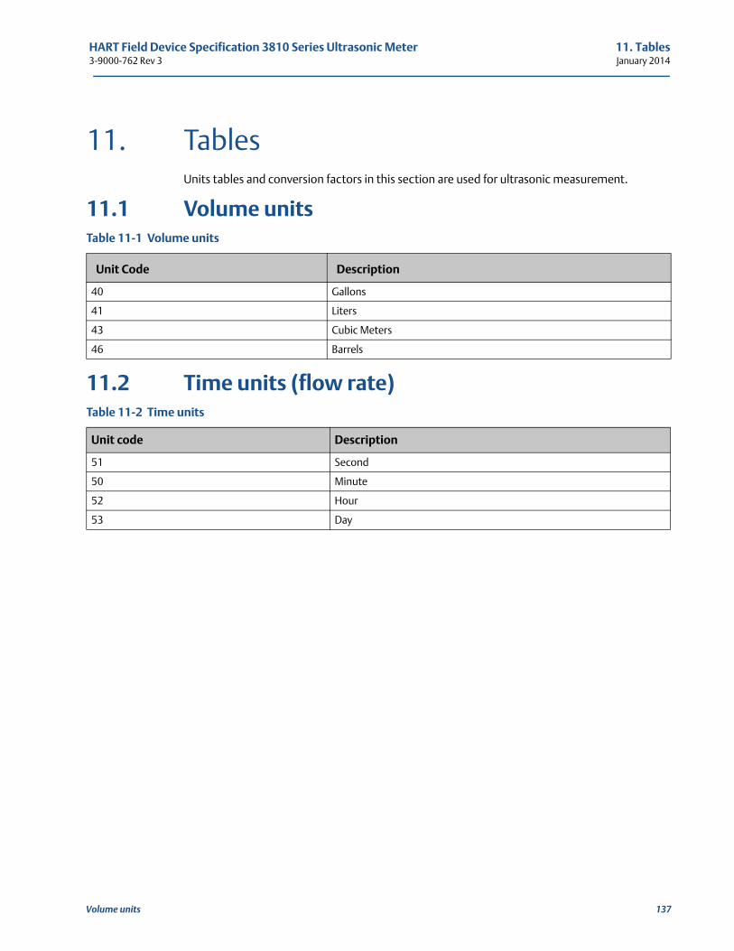
HART Field Device Specification 3810 Series Ultrasonic Meter 11. Tables3-9000-762 Rev 3 January 2014
111
11. TablesUnits tables and conversion factors in this section are used for ultrasonic measurement.
11.1 Volume units
11.2 Time units (flow rate)
Table 11-1 Volume units
Unit Code Description
40 Gallons
41 Liters
43 Cubic Meters
46 Barrels
Table 11-2 Time units
Unit code Description
51 Second
50 Minute
52 Hour
53 Day
Volume units 137
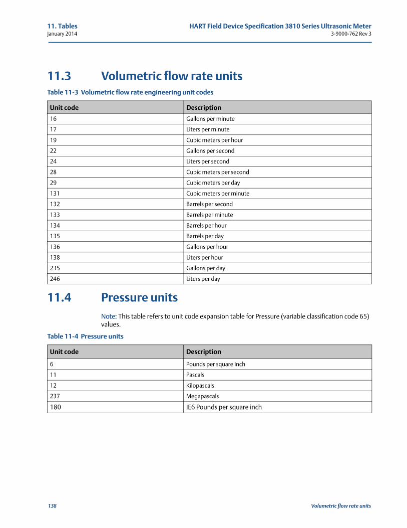
11. Tables HART Field Device Specification 3810 Series Ultrasonic MeterJanuary 2014 3-9000-762 Rev 3
11.3 Volumetric flow rate units
11.4 Pressure unitsNote: This table refers to unit code expansion table for Pressure (variable classification code 65) values.
Table 11-3 Volumetric flow rate engineering unit codes
Unit code Description
16 Gallons per minute
17 Liters per minute
19 Cubic meters per hour
22 Gallons per second
24 Liters per second
28 Cubic meters per second
29 Cubic meters per day
131 Cubic meters per minute
132 Barrels per second
133 Barrels per minute
134 Barrels per hour
135 Barrels per day
136 Gallons per hour
138 Liters per hour
235 Gallons per day
246 Liters per day
Table 11-4 Pressure units
Unit code Description
6 Pounds per square inch
11 Pascals
12 Kilopascals
237 Megapascals
180 IE6 Pounds per square inch
138 Volumetric flow rate units
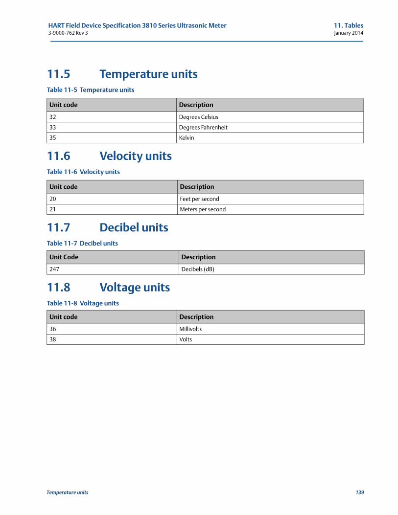
HART Field Device Specification 3810 Series Ultrasonic Meter 11. Tables3-9000-762 Rev 3 January 2014
11.5 Temperature units
11.6 Velocity units
11.7 Decibel units
11.8 Voltage units
Table 11-5 Temperature units
Unit code Description
32 Degrees Celsius
33 Degrees Fahrenheit
35 Kelvin
Table 11-6 Velocity units
Unit code Description
20 Feet per second
21 Meters per second
Table 11-7 Decibel units
Unit Code Description
247 Decibels (dB)
Table 11-8 Voltage units
Unit code Description
36 Millivolts
38 Volts
Temperature units 139
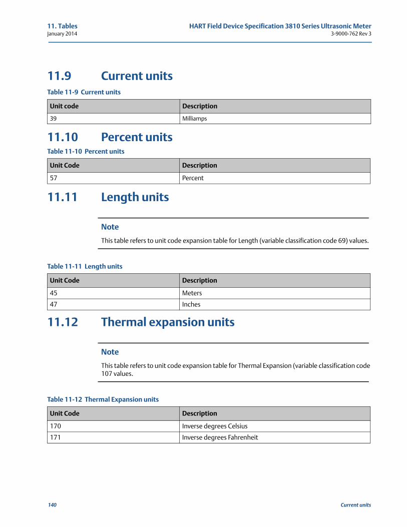
11. Tables HART Field Device Specification 3810 Series Ultrasonic MeterJanuary 2014 3-9000-762 Rev 3
11.9 Current units
11.10 Percent units
11.11 Length units
Note
This table refers to unit code expansion table for Length (variable classification code 69) values.
11.12 Thermal expansion units
Note
This table refers to unit code expansion table for Thermal Expansion (variable classification code 107 values.
Table 11-9 Current units
Unit code Description
39 Milliamps
Table 11-10 Percent units
Unit Code Description
57 Percent
Table 11-11 Length units
Unit Code Description
45 Meters
47 Inches
Table 11-12 Thermal Expansion units
Unit Code Description
170 Inverse degrees Celsius
171 Inverse degrees Fahrenheit
140 Current units
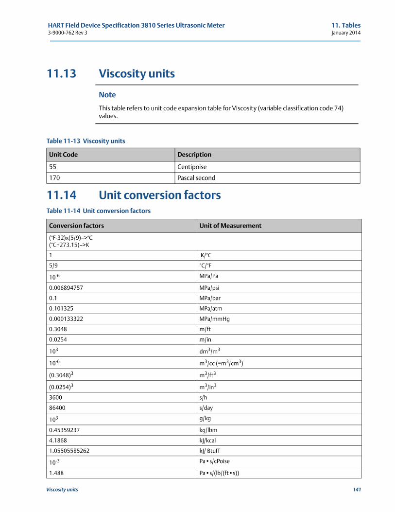
HART Field Device Specification 3810 Series Ultrasonic Meter 11. Tables3-9000-762 Rev 3 January 2014
Viscosity units 141
11.13 Viscosity units
Note
This table refers to unit code expansion table for Viscosity (variable classification code 74) values.
11.14 Unit conversion factors
Table 11-13 Viscosity units
Unit Code Description
55 Centipoise
170 Pascal second
Table 11-14 Unit conversion factors
Conversion factors Unit of Measurement
(°F-32)x(5/9)—>°C(°C+273.15)—>K
1 K/°C
5/9 °C/°F
10-6 MPa/Pa
0.006894757 MPa/psi
0.1 MPa/bar
0.101325 MPa/atm
0.000133322 MPa/mmHg
0.3048 m/ft
0.0254 m/in
103 dm3/m3
10-6 m3/cc (=m3/cm3)
(0.3048)3 m3/ft3
(0.0254)3 m3/in3
3600 s/h
86400 s/day
103 g/kg
0.45359237 kg/lbm
4.1868 kJ/kcal
1.05505585262 kJ/ BtuIT
10-3 Pa•s/cPoise
1.488 Pa•s/(lb/(ft•s))
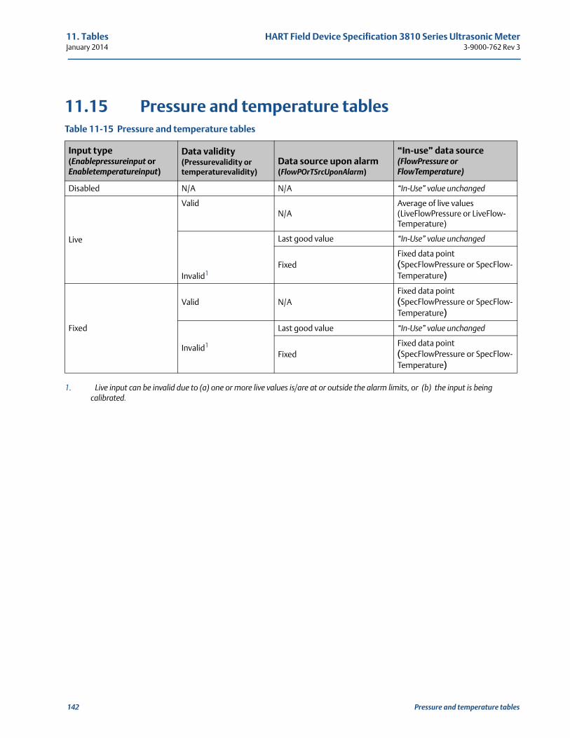
11. Tables HART Field Device Specification 3810 Series Ultrasonic MeterJanuary 2014 3-9000-762 Rev 3
11.15 Pressure and temperature tablesTable 11-15 Pressure and temperature tables
Input type(Enablepressureinput or Enabletemperatureinput)
Data validity(Pressurevalidity or temperaturevalidity)
Data source upon alarm(FlowPOrTSrcUponAlarm)
“In-use” data source(FlowPressure or FlowTemperature)
Disabled N/A N/A “In-Use” value unchanged
Live
ValidN/A
Average of live values(LiveFlowPressure or LiveFlow-Temperature)
Invalid1
1. Live input can be invalid due to (a) one or more live values is/are at or outside the alarm limits, or (b) the input is being calibrated.
Last good value “In-Use” value unchanged
FixedFixed data point(SpecFlowPressure or SpecFlow-Temperature)
Fixed
Valid N/AFixed data point(SpecFlowPressure or SpecFlow-Temperature)
Invalid1
Last good value “In-Use” value unchanged
FixedFixed data point(SpecFlowPressure or SpecFlow-Temperature)
142 Pressure and temperature tables
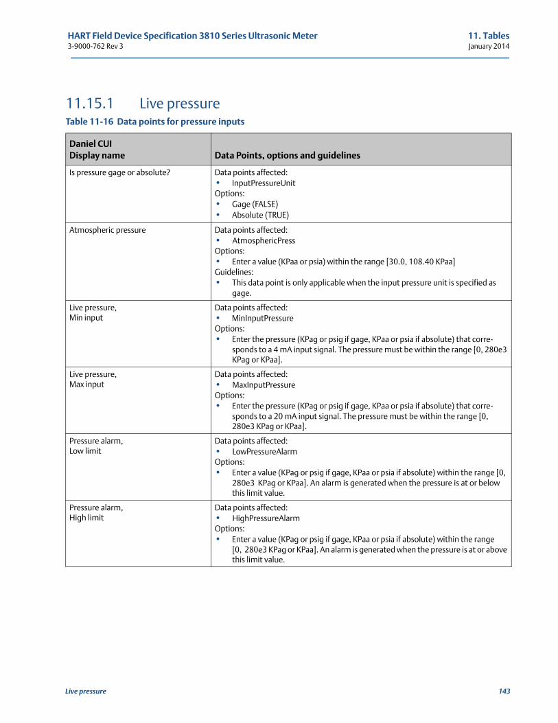
HART Field Device Specification 3810 Series Ultrasonic Meter 11. Tables3-9000-762 Rev 3 January 2014
11.15.1 Live pressureTable 11-16 Data points for pressure inputs
Daniel CUIDisplay name Data Points, options and guidelines
Is pressure gage or absolute? Data points affected:• InputPressureUnitOptions:• Gage (FALSE)• Absolute (TRUE)
Atmospheric pressure Data points affected:• AtmosphericPressOptions:• Enter a value (KPaa or psia) within the range [30.0, 108.40 KPaa]Guidelines:• This data point is only applicable when the input pressure unit is specified as
gage.
Live pressure,Min input
Data points affected:• MinInputPressureOptions:• Enter the pressure (KPag or psig if gage, KPaa or psia if absolute) that corre-
sponds to a 4 mA input signal. The pressure must be within the range [0, 280e3 KPag or KPaa].
Live pressure,Max input
Data points affected:• MaxInputPressureOptions:• Enter the pressure (KPag or psig if gage, KPaa or psia if absolute) that corre-
sponds to a 20 mA input signal. The pressure must be within the range [0, 280e3 KPag or KPaa].
Pressure alarm, Low limit
Data points affected:• LowPressureAlarmOptions:• Enter a value (KPag or psig if gage, KPaa or psia if absolute) within the range [0,
280e3 KPag or KPaa]. An alarm is generated when the pressure is at or below this limit value.
Pressure alarm, High limit
Data points affected:• HighPressureAlarmOptions:• Enter a value (KPag or psig if gage, KPaa or psia if absolute) within the range
[0, 280e3 KPag or KPaa]. An alarm is generated when the pressure is at or above this limit value.
Live pressure 143
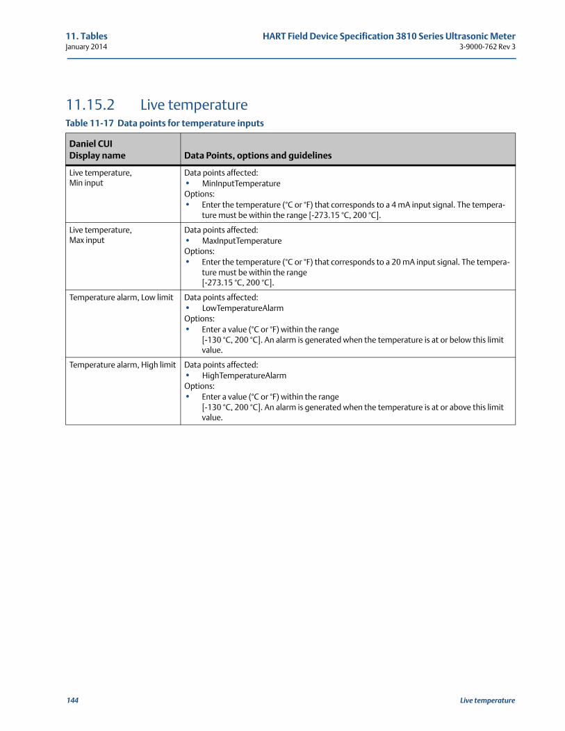
11. Tables HART Field Device Specification 3810 Series Ultrasonic MeterJanuary 2014 3-9000-762 Rev 3
11.15.2 Live temperature Table 11-17 Data points for temperature inputs
Daniel CUI Display name Data Points, options and guidelines
Live temperature,Min input
Data points affected:• MinInputTemperatureOptions:• Enter the temperature (°C or °F) that corresponds to a 4 mA input signal. The tempera-
ture must be within the range [-273.15 °C, 200 °C].
Live temperature,Max input
Data points affected:• MaxInputTemperatureOptions:• Enter the temperature (°C or °F) that corresponds to a 20 mA input signal. The tempera-
ture must be within the range [-273.15 °C, 200 °C].
Temperature alarm, Low limit Data points affected:• LowTemperatureAlarmOptions:• Enter a value (°C or °F) within the range
[-130 °C, 200 °C]. An alarm is generated when the temperature is at or below this limit value.
Temperature alarm, High limit Data points affected:• HighTemperatureAlarmOptions:• Enter a value (°C or °F) within the range
[-130 °C, 200 °C]. An alarm is generated when the temperature is at or above this limit value.
144 Live temperature
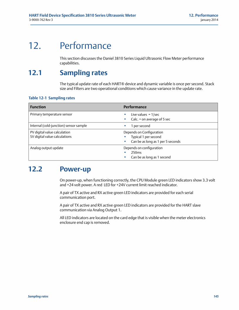
HART Field Device Specification 3810 Series Ultrasonic Meter 12. Performance3-9000-762 Rev 3 January 2014
12
12. PerformanceThis section discusses the Daniel 3810 Series Liquid Ultrasonic Flow Meter performance capabilities.
12.1 Sampling ratesThe typical update rate of each HART® device and dynamic variable is once per second. Stack size and Filters are two operational conditions which cause variance in the update rate.
12.2 Power-upOn power-up, when functioning correctly, the CPU Module green LED indicators show 3.3 volt and +24 volt power. A red LED for +24V current limit reached indicator.
A pair of TX active and RX active green LED indicators are provided for each serial communication port.
A pair of TX active and RX active green LED indicators are provided for the HART slave communication via Analog Output 1.
All LED indicators are located on the card edge that is visible when the meter electronics enclosure end cap is removed.
Table 12-1 Sampling rates
Function Performance
Primary temperature sensor • Live values = 1/sec• Calc. = on average of 5 sec
Internal (cold-junction) sensor sample • 1 per second
PV digital value calculationSV digital value calculations
Depends on Configuration• Typical 1 per second• Can be as long as 1 per 5 seconds
Analog output update Depends on configuration• 250ms• Can be as long as 1 second
Sampling rates 145
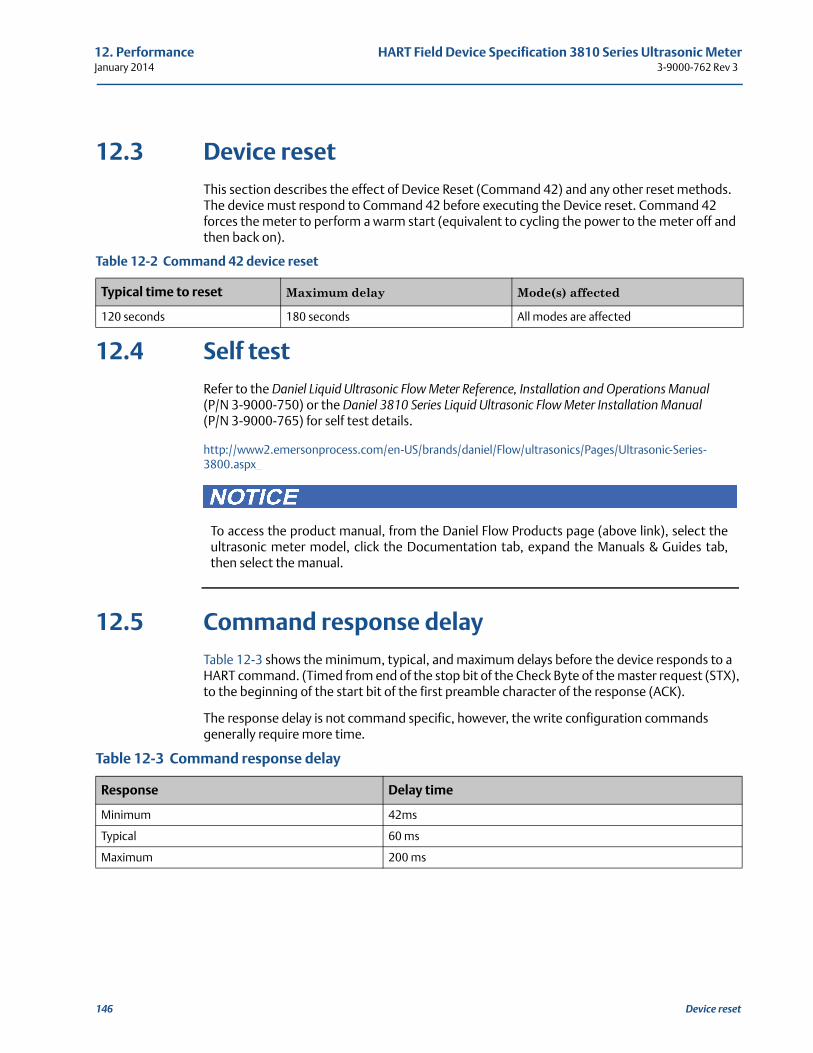
12. Performance HART Field Device Specification 3810 Series Ultrasonic MeterJanuary 2014 3-9000-762 Rev 3
12.3 Device resetThis section describes the effect of Device Reset (Command 42) and any other reset methods. The device must respond to Command 42 before executing the Device reset. Command 42 forces the meter to perform a warm start (equivalent to cycling the power to the meter off and then back on).
12.4 Self testRefer to the Daniel Liquid Ultrasonic Flow Meter Reference, Installation and Operations Manual (P/N 3-9000-750) or the Daniel 3810 Series Liquid Ultrasonic Flow Meter Installation Manual (P/N 3-9000-765) for self test details.
http://www2.emersonprocess.com/en-US/brands/daniel/Flow/ultrasonics/Pages/Ultrasonic-Series-3800.aspx
12.5 Command response delayTable 12-3 shows the minimum, typical, and maximum delays before the device responds to a HART command. (Timed from end of the stop bit of the Check Byte of the master request (STX), to the beginning of the start bit of the first preamble character of the response (ACK).
The response delay is not command specific, however, the write configuration commands generally require more time.
Table 12-2 Command 42 device reset
Typical time to reset Maximum delay Mode(s) affected
120 seconds 180 seconds All modes are affected
Table 12-3 Command response delay
Response Delay time
Minimum 42ms
Typical 60 ms
Maximum 200 ms
To access the product manual, from the Daniel Flow Products page (above link), select theultrasonic meter model, click the Documentation tab, expand the Manuals & Guides tab,then select the manual.
146 Device reset
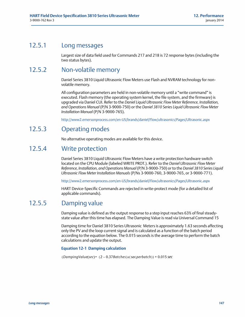
HART Field Device Specification 3810 Series Ultrasonic Meter 12. Performance3-9000-762 Rev 3 January 2014
12.5.1 Long messagesLargest size of data field used for Commands 217 and 218 is 72 response bytes (including the two status bytes).
12.5.2 Non-volatile memoryDaniel Series 3810 Liquid Ultrasonic Flow Meters use Flash and NVRAM technology for non-volatile memory.
All configuration parameters are held in non-volatile memory until a “write command” is executed. Flash memory (the operating system kernel, the file system, and the firmware) is upgraded via Daniel CUI. Refer to the Daniel Liquid Ultrasonic Flow Meter Reference, Installation, and Operations Manual (P/N 3-9000-750) or the Daniel 3810 Series Liquid Ultrasonic Flow Meter Installation Manual (P/N 3-9000-765).
http://www2.emersonprocess.com/en-US/brands/daniel/Flow/ultrasonics/Pages/Ultrasonic.aspx
12.5.3 Operating modesNo alternative operating modes are available for this device.
12.5.4 Write protectionDaniel Series 3810 Liquid Ultrasonic Flow Meters have a write protection hardware switch located on the CPU Module (labeled WRITE PROT.). Refer to the Daniel Ultrasonic Flow Meter Reference, Installation, and Operations Manual (P/N 3-9000-750) or to the Daniel 3810 Series Liquid Ultrasonic Flow Meter Installation Manuals (P/Ns 3-9000-760, 3-9000-765, or 3-9000-771).
http://www2.emersonprocess.com/en-US/brands/daniel/Flow/ultrasonics/Pages/Ultrasonic.aspx
HART Device-Specific Commands are rejected in write-protect mode (for a detailed list of applicable commands).
12.5.5 Damping valueDamping value is defined as the output response to a step input reaches 63% of final steady-state value after this time has elapsed. The Damping Value is read via Universal Command 15
Damping time for Daniel 3810 Series Ultrasonic Meters is approximately 1.63 seconds affecting only the PV and the loop current signal and is calculated as a function of the batch period according to the equation below. The 0.015 seconds is the average time to perform the batch calculations and update the output.
Equation 12-1 Damping calculation
sec
DampingValue sec( ) 2 0.37Batches–( )x perbatchsec( )=( ) 0.015+
Long messages 147
12. Performance HART Field Device Specification 3810 Series Ultrasonic MeterJanuary 2014 3-9000-762 Rev 3
148 Damping value
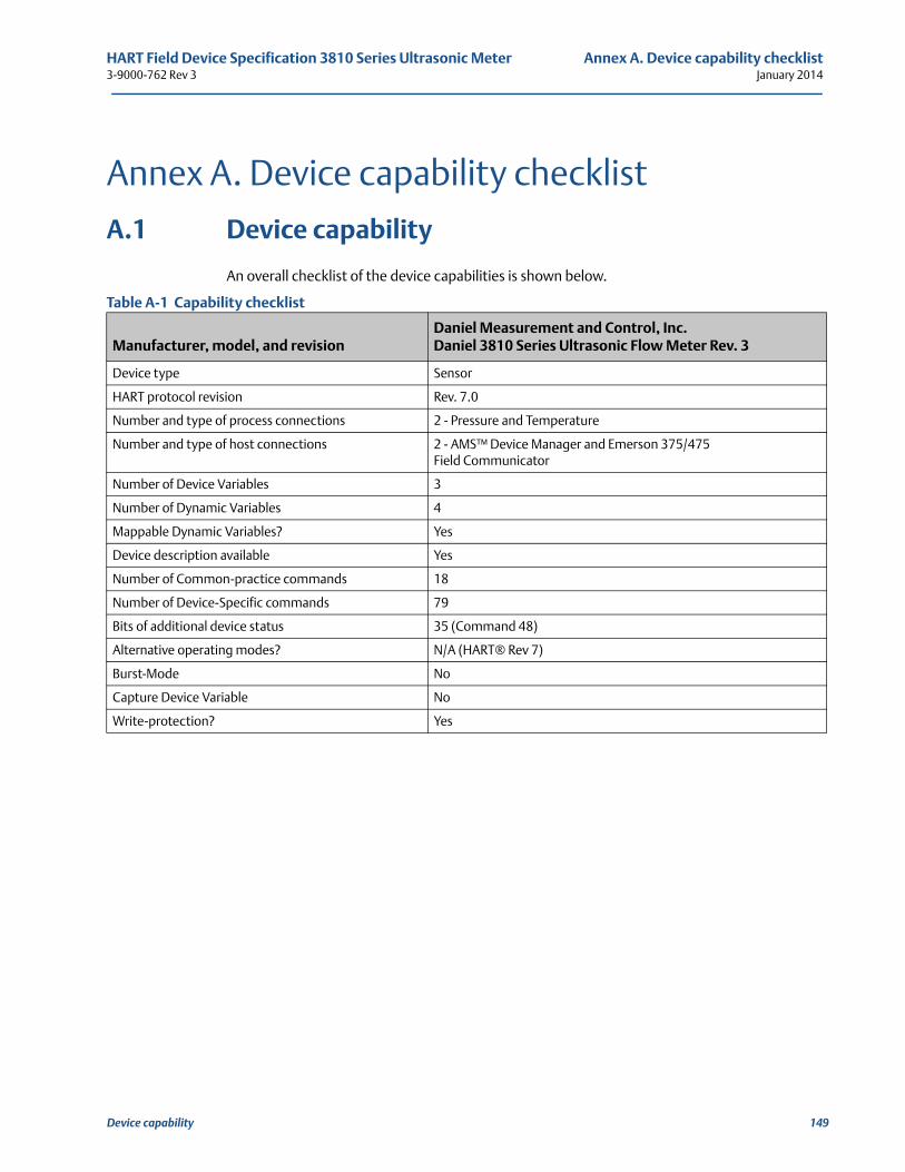
HART Field Device Specification 3810 Series Ultrasonic Meter Annex A. Device capability checklist3-9000-762 Rev 3 January 2014
A
Annex A. Device capability checklist
A.1 Device capability
An overall checklist of the device capabilities is shown below.
Table A-1 Capability checklist
Manufacturer, model, and revisionDaniel Measurement and Control, Inc.Daniel 3810 Series Ultrasonic Flow Meter Rev. 3
Device type Sensor
HART protocol revision Rev. 7.0
Number and type of process connections 2 - Pressure and Temperature
Number and type of host connections 2 - AMS™ Device Manager and Emerson 375/475 Field Communicator
Number of Device Variables 3
Number of Dynamic Variables 4
Mappable Dynamic Variables? Yes
Device description available Yes
Number of Common-practice commands 18
Number of Device-Specific commands 79
Bits of additional device status 35 (Command 48)
Alternative operating modes? N/A (HART® Rev 7)
Burst-Mode No
Capture Device Variable No
Write-protection? Yes
Device capability 149
Annex A. Device capability checklist HART Field Device Specification 3810 Series Ultrasonic MeterJanuary 2014 3-9000-762 Rev 3
150 Device capability
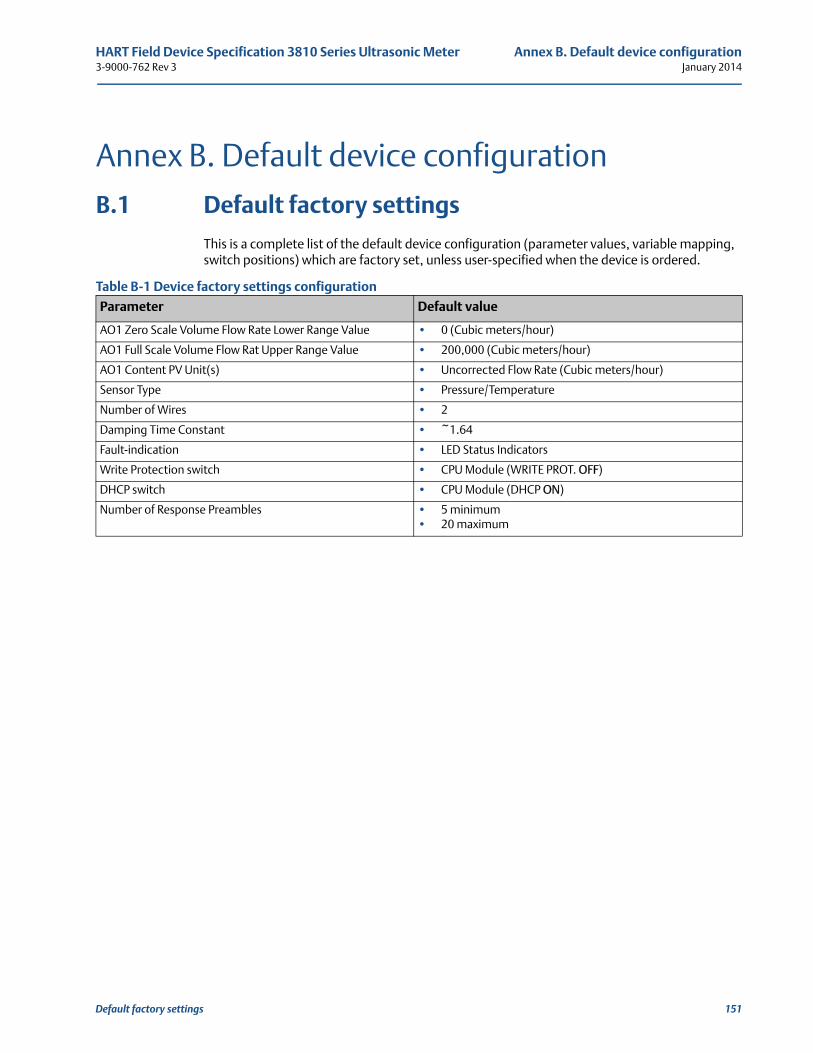
HART Field Device Specification 3810 Series Ultrasonic Meter Annex B. Default device configuration3-9000-762 Rev 3 January 2014
B
Annex B. Default device configurationB.1 Default factory settings
This is a complete list of the default device configuration (parameter values, variable mapping, switch positions) which are factory set, unless user-specified when the device is ordered.
Table B-1 Device factory settings configuration
Parameter Default value
AO1 Zero Scale Volume Flow Rate Lower Range Value • 0 (Cubic meters/hour)
AO1 Full Scale Volume Flow Rat Upper Range Value • 200,000 (Cubic meters/hour)
AO1 Content PV Unit(s) • Uncorrected Flow Rate (Cubic meters/hour)
Sensor Type • Pressure/Temperature
Number of Wires • 2
Damping Time Constant • ~1.64
Fault-indication • LED Status Indicators
Write Protection switch • CPU Module (WRITE PROT. OFF)
DHCP switch • CPU Module (DHCP ON)
Number of Response Preambles • 5 minimum• 20 maximum
Default factory settings 151
Annex B. Default device configuration HART Field Device Specification 3810 Series Ultrasonic MeterJanuary 2014 3-9000-762 Rev 3
152 Default factory settings
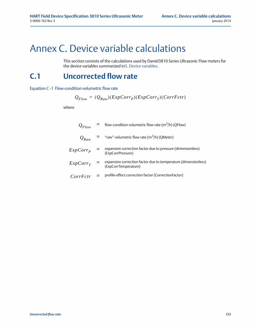
HART Field Device Specification 3810 Series Ultrasonic Meter Annex C. Device variable calculations3-9000-762 Rev 3 January 2014
C
Annex C. Device variable calculationsThis section consists of the calculations used by Daniel3810 Series Ultrasonic Flow meters for the device variables summarized in5. Device variables.
C.1 Uncorrected flow rate
Equation C -1 Flow-condition volumetric flow rate
where
= flow-condition volumetric flow rate (m3/h) (QFlow)
= “raw” volumetric flow rate (m3/h) (QMeter)
= expansion correction factor due to pressure (dimensionless) (ExpCorrPressure)
= expansion correction factor due to temperature (dimensionless) (ExpCorrTemperature)
= profile-effect correction factor (CorrectionFactor)
QFlow QRaw( ) ExpCorrP( ) ExpCorrT( ) CorrFctr( )=
QFlow
QRaw
ExpCorrP
ExpCorrT
CorrFctr
Uncorrected flow rate 153
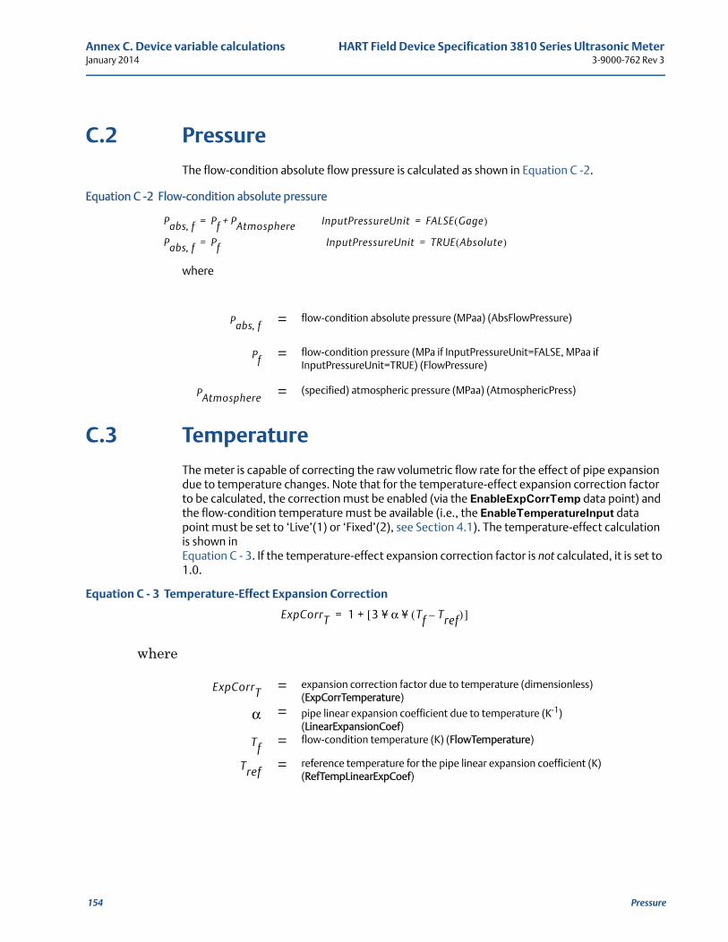
Annex C. Device variable calculations HART Field Device Specification 3810 Series Ultrasonic MeterJanuary 2014 3-9000-762 Rev 3
C.2 Pressure
The flow-condition absolute flow pressure is calculated as shown in Equation C -2.
Equation C -2 Flow-condition absolute pressure
where
C.3 Temperature
The meter is capable of correcting the raw volumetric flow rate for the effect of pipe expansion due to temperature changes. Note that for the temperature-effect expansion correction factor to be calculated, the correction must be enabled (via the EnableExpCorrTemp data point) and the flow-condition temperature must be available (i.e., the EnableTemperatureInput data point must be set to ‘Live’(1) or ‘Fixed’(2), see Section 4.1). The temperature-effect calculation is shown in Equation C - 3. If the temperature-effect expansion correction factor is not calculated, it is set to 1.0.
Equation C - 3 Temperature-Effect Expansion Correction
where
= flow-condition absolute pressure (MPaa) (AbsFlowPressure)
= flow-condition pressure (MPa if InputPressureUnit=FALSE, MPaa if InputPressureUnit=TRUE) (FlowPressure)
= (specified) atmospheric pressure (MPaa) (AtmosphericPress)
= expansion correction factor due to temperature (dimensionless) (ExpCorrTemperature)
= pipe linear expansion coefficient due to temperature (K-1) (LinearExpansionCoef)
= flow-condition temperature (K) (FlowTemperature)
= reference temperature for the pipe linear expansion coefficient (K) (RefTempLinearExpCoef)
Pabs f, Pf PAtmosphere+= InputPressureUnit FALSE Gage( )=
Pabs f, Pf= InputPressureUnit TRUE Absolute( )=
Pabs f,
Pf
PAtmosphere
ExpCorrT 1 3 α¥ Tf Tref–( )¥[ ]+=
ExpCorrT
α
Tf
Tref
154 Pressure
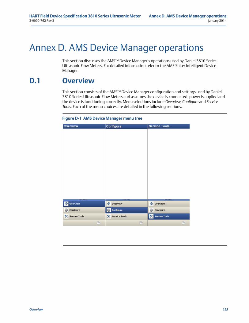
HART Field Device Specification 3810 Series Ultrasonic Meter Annex D. AMS Device Manager operations3-9000-762 Rev 3 January 2014
Overview 155
D
Annex D. AMS Device Manager operationsThis section discusses the AMS™ Device Manager’s operations used by Daniel 3810 Series Ultrasonic Flow Meters. For detailed information refer to the AMS Suite: Intelligent Device Manager.
D.1 OverviewThis section consists of the AMS™ Device Manager configuration and settings used by Daniel 3810 Series Ultrasonic Flow Meters and assumes the device is connected, power is applied and the device is functioning correctly. Menu selections include Overview, Configure and Service Tools. Each of the menu choices are detailed in the following sections.
Figure D-1 AMS Device Manager menu tree
Annex D. AMS Device Manager operations HART Field Device Specification 3810 Series Ultrasonic MeterJanuary 2014 3-9000-762 Rev 3
D.2 375/475 field communicator menu tree
The 375/475 Field Communicator provides real-time HART communications with Daniel 3810 Series Ultrasonic Flow Meters.
The following figures show details of the 375 Handheld Communicator Menu Tree.
• Diagram Page 1 - 3810 Series Root Menu; HART Application, Online menu, Utility menu, HART diagnostics
• Diagram Page 2 - 8 Configure>Manual Setup
• Diagram Page 9 Configure Alerts Setup and Variables
• Diagram Page 10 Service Tools> All Variables| Trends | Maintenance
156 375/475 field communicator menu tree
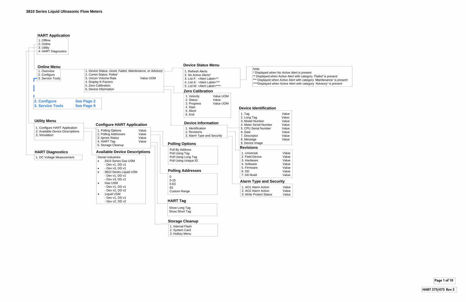
1. Device Status: Good, Failed, Maintenance, or Advisory
2. Comm Status: Polled
3. Uncorr Volume Rate Value UOM4. Display K-Factors5. Zero Calibration6. Device Information
3810 Series Liquid Ultrasonic Flow Meters
Online Menu Device Status Menu
1. Refresh Alerts2. No Active Alerts* 3. List F: <Alert Label>**4. List A: <Alert Label>***5. List M: <Alert Label>****
1. Identification2. Revisions3. Alarm Type and Security
Device Information
1. Tag Value2. Long Tag Value3. Model Number Value4. Meter Serial Number Value5. CPU Serial Number Value6. Date Value7. Descriptor Value8. Message Value9. Device Image
Device Identification
1. Universal Value2. Field Device Value3. Hardware Value4. Software Value5. Firmware Value6. DD Value7. DD Build Value
Revisions
1. AO1 Alarm Action Value2. AO2 Alarm Action Value3. Write Protect Status Value
Alarm Type and Security
Page 1 of 10
Note
* Displayed when No Active Alert is present** Displayed when Active Alert with category ‘Failed’ is present*** Displayed when Active Alert with category ‘Maintenance’ is present****Displayed when Active Alert with category ‘Advisory’ is present
HART 375/475 Rev 3
1. Overview2. Configure3. Service Tools
1. Configure HART Application2. Available Device Descriptions3. Simulation
Utility Menu
1. DC Voltage MeasurementHART Diagnostics
1. Polling Options Value2. Polling Addresses Value3. Ignore Status Value4. HART Tag Value5. Storage Cleanup
Configure HART Application
Poll By AddressPoll Using TagPoll Using Long TagPoll Using Unique ID
Polling Options
00-150-6363Custom Range
Polling Addresses
Show Long TagShow Short Tag
HART Tag
1. Internal Flash2. System Card3. Hotkey Menu
Storage Cleanup
1. Offline2. Online3. Utility4. HART Diagnostics
Daniel Industries· 3410 Series Gas USM
- Dev v1, DD v1· - Dev v3, DD v1· 3810 Series Liquid USM - Dev v1, DD v1 - Dev v3, DD v1· Gas USM - Dev v1, DD v1 - Dev v2, DD v2· Liquid USM - Dev v1, DD v1 - Dev v2, DD v2
Available Device Descriptions
HART Application
2. Configure See Page 2
3. Service Tools See Page 9
1. Velocity Value UOM2. Status Value3. Progress Value UOM4. Start5. Abort6. End
Zero Calibration
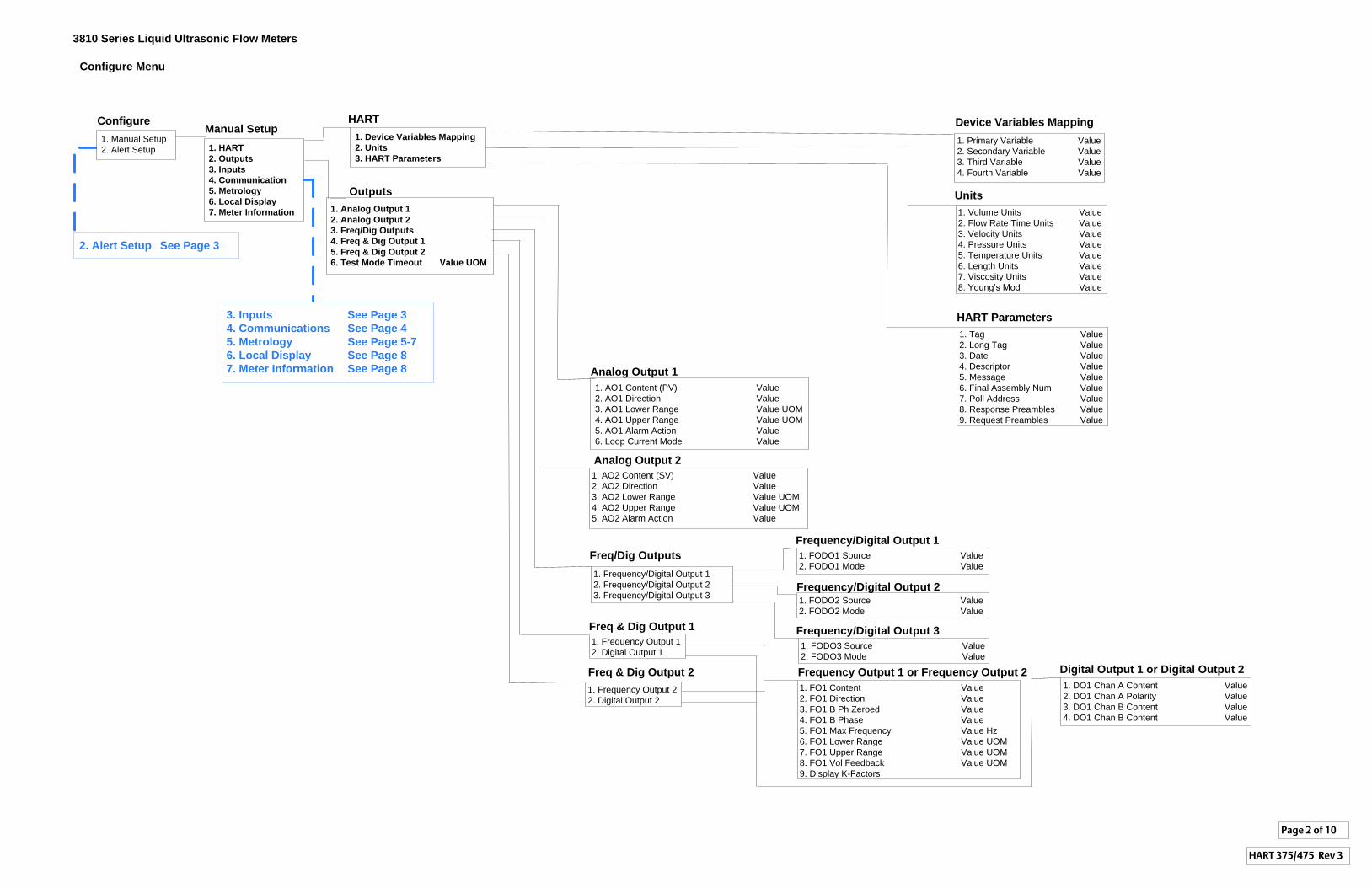
3810 Series Liquid Ultrasonic Flow Meters
Page 2 of 10
HART 375/475 Rev 3
Configure Menu
Outputs
Analog Output 1
Analog Output 2
1. AO2 Content (SV) Value2. AO2 Direction Value3. AO2 Lower Range Value UOM4. AO2 Upper Range Value UOM5. AO2 Alarm Action Value
Freq/Dig Outputs
1. Frequency/Digital Output 12. Frequency/Digital Output 23. Frequency/Digital Output 3
Freq & Dig Output 1
1. Frequency Output 12. Digital Output 1
Freq & Dig Output 2
1. Frequency Output 22. Digital Output 2
Frequency/Digital Output 1
1. FODO1 Source Value2. FODO1 Mode Value
Frequency/Digital Output 2 1. FODO2 Source Value2. FODO2 Mode Value
Frequency/Digital Output 3
1. FODO3 Source Value2. FODO3 Mode Value
Frequency Output 1 or Frequency Output 2
1. FO1 Content Value2. FO1 Direction Value3. FO1 B Ph Zeroed Value4. FO1 B Phase Value5. FO1 Max Frequency Value Hz6. FO1 Lower Range Value UOM7. FO1 Upper Range Value UOM8. FO1 Vol Feedback Value UOM9. Display K-Factors
Digital Output 1 or Digital Output 2
1. DO1 Chan A Content Value2. DO1 Chan A Polarity Value3. DO1 Chan B Content Value4. DO1 Chan B Content Value
1. AO1 Content (PV) Value2. AO1 Direction Value3. AO1 Lower Range Value UOM4. AO1 Upper Range Value UOM5. AO1 Alarm Action Value 6. Loop Current Mode Value
1. Analog Output 1
2. Analog Output 2
3. Freq/Dig Outputs
4. Freq & Dig Output 1
5. Freq & Dig Output 2
6. Test Mode Timeout Value UOM
2. Alert Setup See Page 3
Manual Setup1. Primary Variable Value2. Secondary Variable Value3. Third Variable Value4. Fourth Variable Value
Units
Device Variables Mapping
1. Volume Units Value2. Flow Rate Time Units Value3. Velocity Units Value4. Pressure Units Value5. Temperature Units Value6. Length Units Value7. Viscosity Units Value8. Young’s Mod Value
1. Tag Value2. Long Tag Value3. Date Value4. Descriptor Value5. Message Value6. Final Assembly Num Value7. Poll Address Value8. Response Preambles Value9. Request Preambles Value
HART Parameters
1. Device Variables Mapping
2. Units
3. HART Parameters
HART
1. HART
2. Outputs
3. Inputs
4. Communication
5. Metrology
6. Local Display
7. Meter Information
1. Manual Setup2. Alert Setup
Configure
3. Inputs See Page 3
4. Communications See Page 4
5. Metrology See Page 5-7
6. Local Display See Page 8
7. Meter Information See Page 8
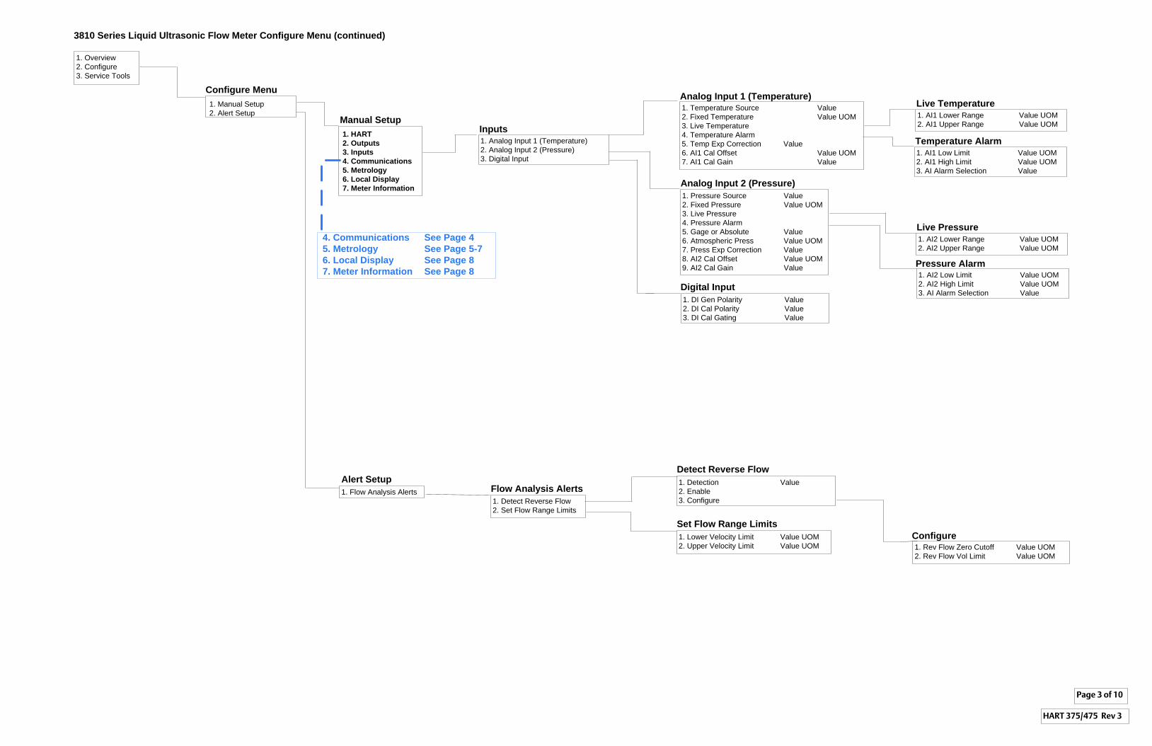
3810 Series Liquid Ultrasonic Flow Meter Configure Menu (continued)
1. Overview2. Configure3. Service Tools
1. Manual Setup2. Alert Setup
Manual Setup
Configure MenuAnalog Input 1 (Temperature)1. Temperature Source Value2. Fixed Temperature Value UOM3. Live Temperature4. Temperature Alarm5. Temp Exp Correction Value 6. AI1 Cal Offset Value UOM7. AI1 Cal Gain Value
Alert Setup
1. Flow Analysis Alerts
Page 3 of 10
HART 375/475 Rev 3
1. HART
2. Outputs
3. Inputs
4. Communications
5. Metrology
6. Local Display
7. Meter Information
Inputs
1. Analog Input 1 (Temperature)2. Analog Input 2 (Pressure)3. Digital Input
Analog Input 2 (Pressure)
1. Pressure Source Value2. Fixed Pressure Value UOM3. Live Pressure4. Pressure Alarm5. Gage or Absolute Value6. Atmospheric Press Value UOM7. Press Exp Correction Value8. AI2 Cal Offset Value UOM9. AI2 Cal Gain Value
Digital Input
1. DI Gen Polarity Value2. DI Cal Polarity Value3. DI Cal Gating Value
4. Communications See Page 4
5. Metrology See Page 5-7
6. Local Display See Page 8
7. Meter Information See Page 8
Temperature Alarm
1. AI1 Low Limit Value UOM2. AI1 High Limit Value UOM3. AI Alarm Selection Value
Live Temperature
1. AI1 Lower Range Value UOM2. AI1 Upper Range Value UOM
Live Pressure
1. AI2 Lower Range Value UOM2. AI2 Upper Range Value UOM
Pressure Alarm1. AI2 Low Limit Value UOM2. AI2 High Limit Value UOM3. AI Alarm Selection Value
1. Detect Reverse Flow2. Set Flow Range Limits
Flow Analysis Alerts
Detect Reverse Flow
1. Detection Value2. Enable3. Configure
Configure1. Rev Flow Zero Cutoff Value UOM2. Rev Flow Vol Limit Value UOM
Set Flow Range Limits
1. Lower Velocity Limit Value UOM2. Upper Velocity Limit Value UOM
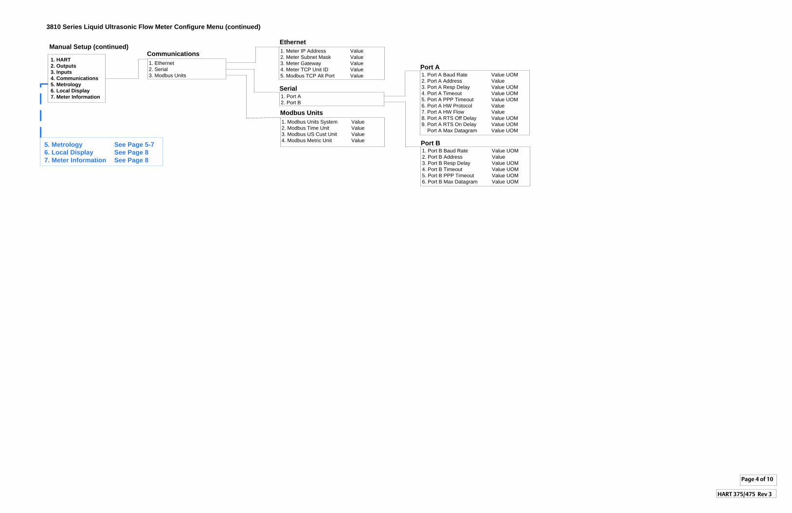
3810 Series Liquid Ultrasonic Flow Meter Configure Menu (continued)
Manual Setup (continued)
1. HART
2. Outputs
3. Inputs
4. Communications
5. Metrology
6. Local Display
7. Meter Information
Communications
1. Ethernet2. Serial3. Modbus Units
1. Meter IP Address Value2. Meter Subnet Mask Value3. Meter Gateway Value4. Meter TCP Unit ID Value5. Modbus TCP Alt Port Value
Ethernet
1. Port A2. Port B
Serial
1. Modbus Units System Value2. Modbus Time Unit Value3. Modbus US Cust Unit Value4. Modbus Metric Unit Value
Modbus Units
Page 4 of 10
HART 375/475 Rev 3
5. Metrology See Page 5-7
6. Local Display See Page 8
7. Meter Information See Page 8
Port B1. Port B Baud Rate Value UOM2. Port B Address Value3. Port B Resp Delay Value UOM4. Port B Timeout Value UOM5. Port B PPP Timeout Value UOM6. Port B Max Datagram Value UOM
Port A1. Port A Baud Rate Value UOM2. Port A Address Value3. Port A Resp Delay Value UOM4. Port A Timeout Value UOM5. Port A PPP Timeout Value UOM6. Port A HW Protocol Value7. Port A HW Flow Value8. Port A RTS Off Delay Value UOM9. Port A RTS On Delay Value UOM Port A Max Datagram Value UOM
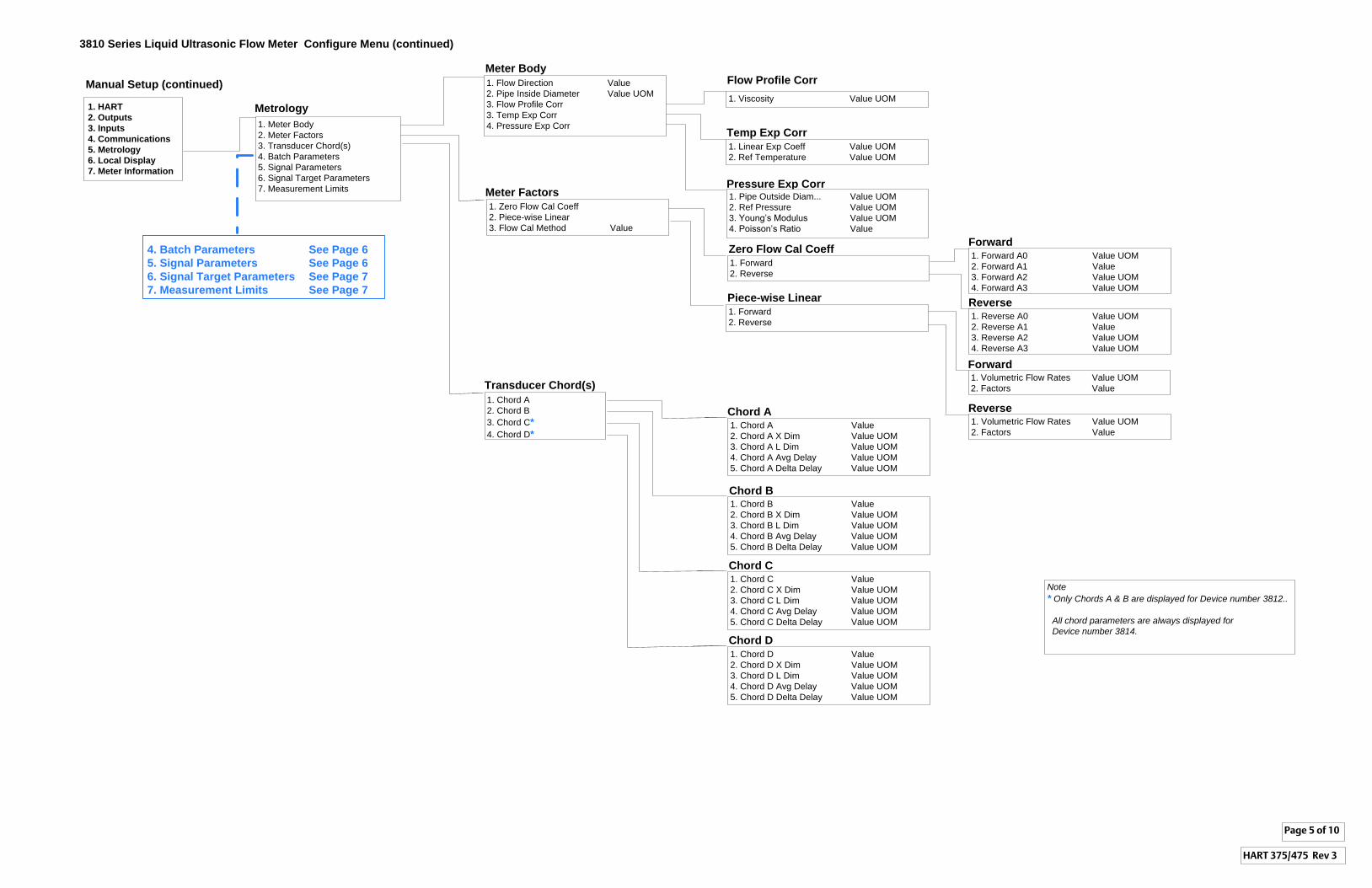
3810 Series Liquid Ultrasonic Flow Meter Configure Menu (continued)
Manual Setup (continued)
1. HART
2. Outputs
3. Inputs
4. Communications
5. Metrology
6. Local Display
7. Meter Information
Metrology
1. Meter Body2. Meter Factors3. Transducer Chord(s)4. Batch Parameters5. Signal Parameters6. Signal Target Parameters7. Measurement Limits
1. Linear Exp Coeff Value UOM2. Ref Temperature Value UOM
Temp Exp Corr
1. Viscosity Value UOM
Pressure Exp Corr
Meter Body
1. Flow Direction Value2. Pipe Inside Diameter Value UOM3. Flow Profile Corr3. Temp Exp Corr4. Pressure Exp Corr
Meter Factors
1. Zero Flow Cal Coeff2. Piece-wise Linear3. Flow Cal Method Value
1. Forward2. Reverse
Zero Flow Cal Coeff
4. Batch Parameters See Page 6
5. Signal Parameters See Page 6
6. Signal Target Parameters See Page 7
7. Measurement Limits See Page 7
Page 5 of 10
HART 375/475 Rev 3
Transducer Chord(s)
1. Chord A2. Chord B3. Chord C*
4. Chord D*1. Chord A Value2. Chord A X Dim Value UOM3. Chord A L Dim Value UOM4. Chord A Avg Delay Value UOM5. Chord A Delta Delay Value UOM
Chord A
1. Chord B Value2. Chord B X Dim Value UOM3. Chord B L Dim Value UOM4. Chord B Avg Delay Value UOM5. Chord B Delta Delay Value UOM
Chord B
1. Chord C Value2. Chord C X Dim Value UOM3. Chord C L Dim Value UOM4. Chord C Avg Delay Value UOM5. Chord C Delta Delay Value UOM
Chord C
1. Chord D Value2. Chord D X Dim Value UOM3. Chord D L Dim Value UOM4. Chord D Avg Delay Value UOM5. Chord D Delta Delay Value UOM
Chord D
1. Forward A0 Value UOM2. Forward A1 Value3. Forward A2 Value UOM4. Forward A3 Value UOM
Forward
1. Reverse A0 Value UOM2. Reverse A1 Value3. Reverse A2 Value UOM4. Reverse A3 Value UOM
Reverse
1. Pipe Outside Diam... Value UOM2. Ref Pressure Value UOM3. Young’s Modulus Value UOM4. Poisson’s Ratio Value
Flow Profile Corr
Note
* Only Chords A & B are displayed for Device number 3812..
All chord parameters are always displayed for
Device number 3814.
1. Forward2. Reverse
Piece-wise Linear
1. Volumetric Flow Rates Value UOM2. Factors Value
Forward
Reverse1. Volumetric Flow Rates Value UOM2. Factors Value
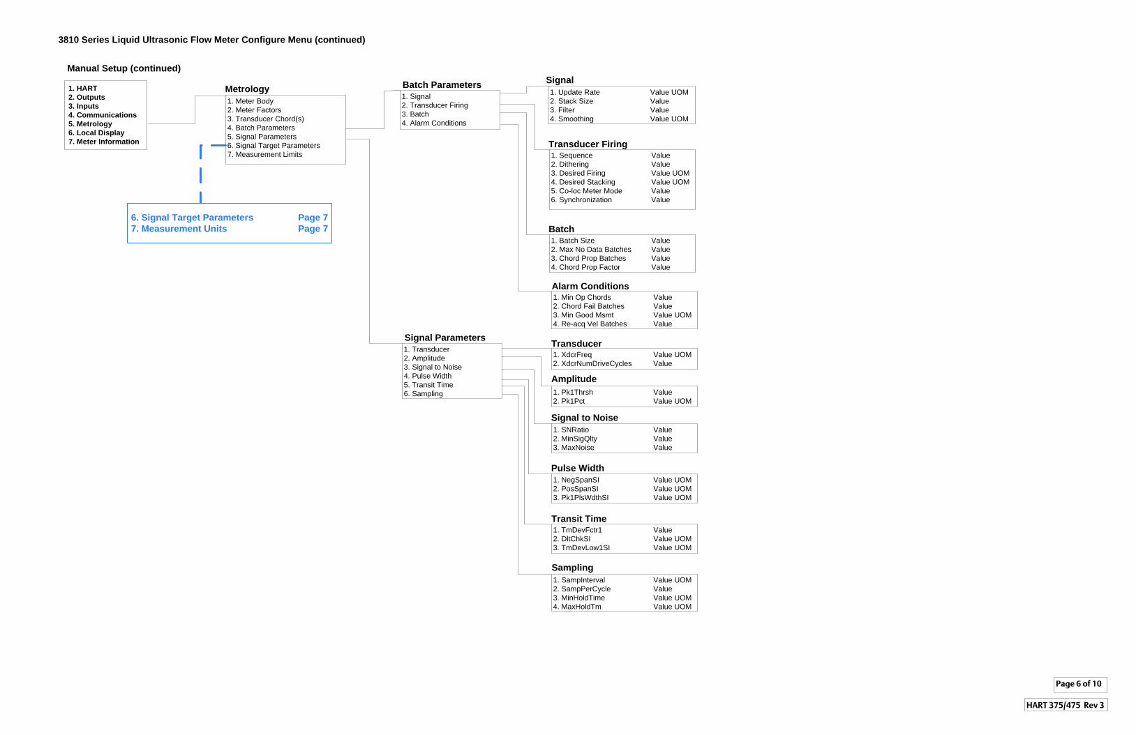
3810 Series Liquid Ultrasonic Flow Meter Configure Menu (continued)
Manual Setup (continued)
Metrology
1. Meter Body2. Meter Factors3. Transducer Chord(s)4. Batch Parameters5. Signal Parameters6. Signal Target Parameters7. Measurement Limits
1. HART
2. Outputs
3. Inputs
4. Communications
5. Metrology
6. Local Display
7. Meter Information
Batch Parameters
1. Signal2. Transducer Firing3. Batch4. Alarm Conditions
1. Batch Size Value2. Max No Data Batches Value3. Chord Prop Batches Value4. Chord Prop Factor Value
Signal
1. Update Rate Value UOM2. Stack Size Value3. Filter Value4. Smoothing Value UOM
Transducer Firing1. Sequence Value2. Dithering Value3. Desired Firing Value UOM4. Desired Stacking Value UOM5. Co-loc Meter Mode Value6. Synchronization Value
Batch
1. Min Op Chords Value2. Chord Fail Batches Value3. Min Good Msmt Value UOM4. Re-acq Vel Batches Value
Alarm Conditions
1. SampInterval Value UOM2. SampPerCycle Value 3. MinHoldTime Value UOM4. MaxHoldTm Value UOM
Sampling
Signal Parameters
1. Transducer2. Amplitude3. Signal to Noise4. Pulse Width5. Transit Time6. Sampling
1. XdcrFreq Value UOM2. XdcrNumDriveCycles Value
Transducer
1. Pk1Thrsh Value2. Pk1Pct Value UOM
Amplitude
1. SNRatio Value2. MinSigQlty Value 3. MaxNoise Value
Signal to Noise
1. NegSpanSI Value UOM2. PosSpanSI Value UOM3. Pk1PlsWdthSI Value UOM
Pulse Width
Transit Time1. TmDevFctr1 Value2. DltChkSI Value UOM3. TmDevLow1SI Value UOM
6. Signal Target Parameters Page 7
7. Measurement Units Page 7
Page 6 of 10
HART 375/475 Rev 3
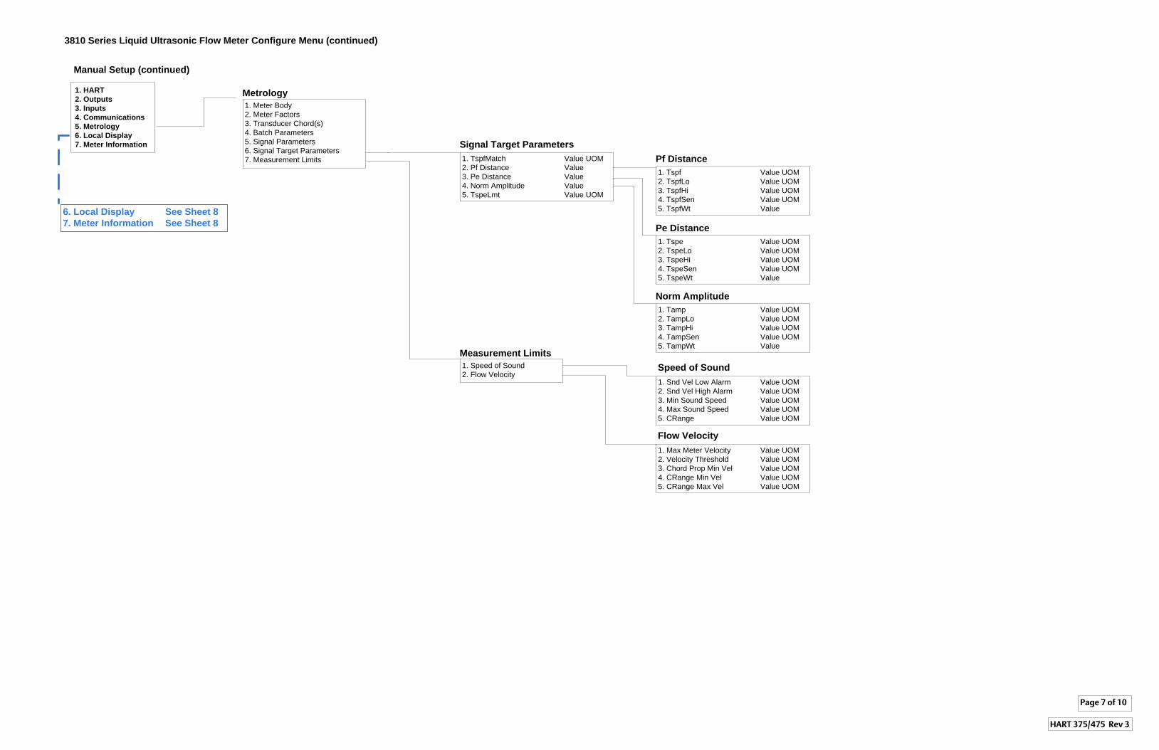
Signal Target Parameters
1. Speed of Sound2. Flow Velocity
Measurement Limits
3810 Series Liquid Ultrasonic Flow Meter Configure Menu (continued)
Manual Setup (continued)
Metrology
1. Meter Body2. Meter Factors3. Transducer Chord(s)4. Batch Parameters5. Signal Parameters6. Signal Target Parameters7. Measurement Limits
1. HART
2. Outputs
3. Inputs
4. Communications
5. Metrology
6. Local Display
7. Meter Information
1. Tspf Value UOM2. TspfLo Value UOM3. TspfHi Value UOM4. TspfSen Value UOM5. TspfWt Value
Pf Distance
1. Tspe Value UOM2. TspeLo Value UOM3. TspeHi Value UOM4. TspeSen Value UOM5. TspeWt Value
Pe Distance
1. TspfMatch Value UOM2. Pf Distance Value3. Pe Distance Value4. Norm Amplitude Value5. TspeLmt Value UOM
1. Tamp Value UOM2. TampLo Value UOM3. TampHi Value UOM4. TampSen Value UOM5. TampWt Value
Norm Amplitude
1. Snd Vel Low Alarm Value UOM2. Snd Vel High Alarm Value UOM3. Min Sound Speed Value UOM4. Max Sound Speed Value UOM5. CRange Value UOM
Speed of Sound
1. Max Meter Velocity Value UOM2. Velocity Threshold Value UOM3. Chord Prop Min Vel Value UOM4. CRange Min Vel Value UOM5. CRange Max Vel Value UOM
Flow Velocity
Page 7 of 10
HART 375/475 Rev 3
6. Local Display See Sheet 8
7. Meter Information See Sheet 8
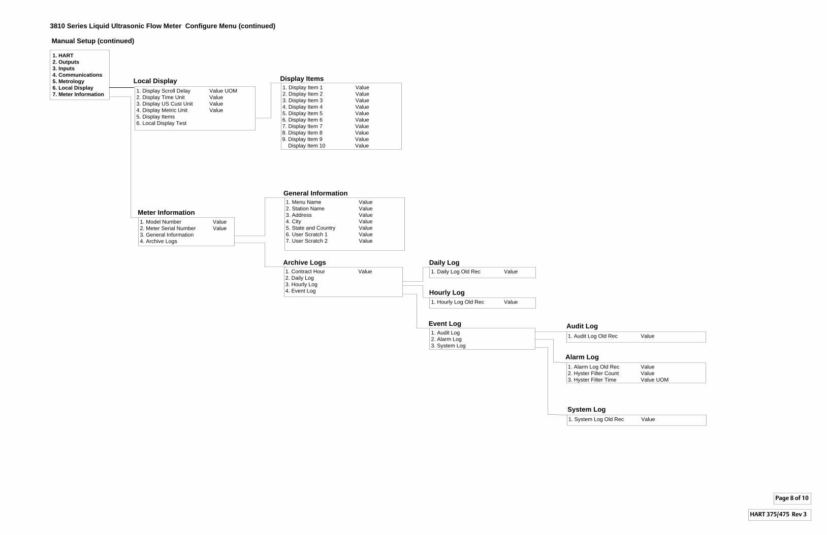
3810 Series Liquid Ultrasonic Flow Meter Configure Menu (continued)
Manual Setup (continued)
1. HART
2. Outputs
3. Inputs
4. Communications
5. Metrology
6. Local Display
7. Meter Information
Local Display
1. Display Scroll Delay Value UOM2. Display Time Unit Value3. Display US Cust Unit Value4. Display Metric Unit Value5. Display Items6. Local Display Test
Page 8 of 10
HART 375/475 Rev 3
Meter Information
1. Model Number Value2. Meter Serial Number Value3. General Information4. Archive Logs
General Information
1. Menu Name Value2. Station Name Value3. Address Value4. City Value5. State and Country Value6. User Scratch 1 Value7. User Scratch 2 Value
Archive Logs
1. Contract Hour Value2. Daily Log3. Hourly Log4. Event Log
Daily Log
1. Daily Log Old Rec Value
Hourly Log
1. Hourly Log Old Rec Value
Event Log
1. Audit Log2. Alarm Log3. System Log
Audit Log
1. Audit Log Old Rec Value
Alarm Log
1. Alarm Log Old Rec Value2. Hyster Filter Count Value3. Hyster Filter Time Value UOM
System Log
1. System Log Old Rec Value
Display Items
1. Display Item 1 Value2. Display Item 2 Value3. Display Item 3 Value4. Display Item 4 Value5. Display Item 5 Value6. Display Item 6 Value7. Display Item 7 Value8. Display Item 8 Value9. Display Item 9 Value Display Item 10 Value
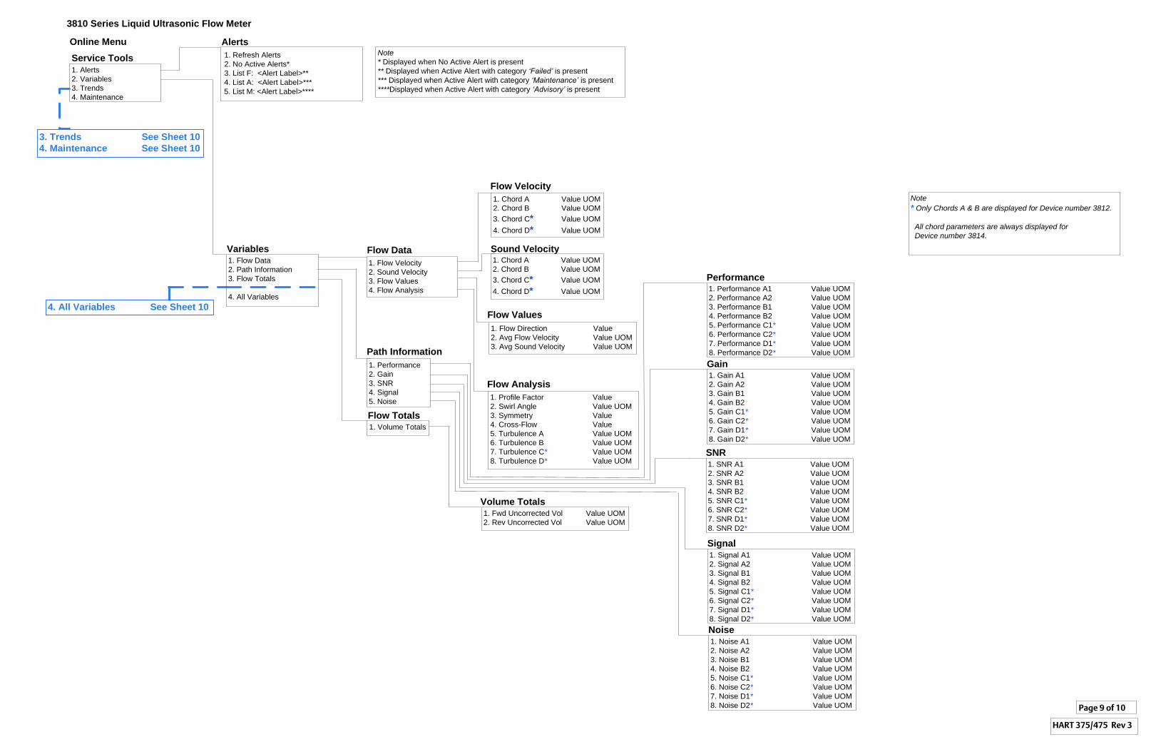
1. Alerts2. Variables3. Trends4. Maintenance
Service Tools
Alerts
Variables1. Flow Data2. Path Information3. Flow Totals
4. All Variables
1. Flow Velocity2. Sound Velocity3. Flow Values4. Flow Analysis
Flow Data
1. Flow Direction Value2. Avg Flow Velocity Value UOM3. Avg Sound Velocity Value UOM
Flow Values
Flow Analysis
1. Profile Factor Value2. Swirl Angle Value UOM3. Symmetry Value4. Cross-Flow Value5. Turbulence A Value UOM6. Turbulence B Value UOM7. Turbulence C* Value UOM8. Turbulence D* Value UOM
1. Performance2. Gain3. SNR4. Signal5. Noise
Path Information
Performance1. Performance A1 Value UOM2. Performance A2 Value UOM3. Performance B1 Value UOM4. Performance B2 Value UOM5. Performance C1* Value UOM6. Performance C2* Value UOM7. Performance D1* Value UOM8. Performance D2* Value UOM
Signal1. Signal A1 Value UOM2. Signal A2 Value UOM3. Signal B1 Value UOM4. Signal B2 Value UOM5. Signal C1* Value UOM6. Signal C2* Value UOM7. Signal D1* Value UOM8. Signal D2* Value UOM
Gain1. Gain A1 Value UOM2. Gain A2 Value UOM3. Gain B1 Value UOM4. Gain B2 Value UOM5. Gain C1* Value UOM6. Gain C2* Value UOM7. Gain D1* Value UOM8. Gain D2* Value UOM
Noise1. Noise A1 Value UOM2. Noise A2 Value UOM3. Noise B1 Value UOM4. Noise B2 Value UOM5. Noise C1* Value UOM6. Noise C2* Value UOM7. Noise D1* Value UOM8. Noise D2* Value UOM
SNR1. SNR A1 Value UOM2. SNR A2 Value UOM3. SNR B1 Value UOM4. SNR B2 Value UOM5. SNR C1* Value UOM6. SNR C2* Value UOM7. SNR D1* Value UOM8. SNR D2* Value UOM
1. Volume TotalsFlow Totals
1. Fwd Uncorrected Vol Value UOM2. Rev Uncorrected Vol Value UOM
Volume Totals
4. All Variables See Sheet 10
Page 9 of 10
1. Refresh Alerts2. No Active Alerts* 3. List F: <Alert Label>**4. List A: <Alert Label>***5. List M: <Alert Label>****
Note
* Displayed when No Active Alert is present** Displayed when Active Alert with category ‘Failed’ is present*** Displayed when Active Alert with category ‘Maintenance’ is present****Displayed when Active Alert with category ‘Advisory’ is present
Sound Velocity
Flow Velocity
1. Chord A Value UOM2. Chord B Value UOM3. Chord C* Value UOM4. Chord D* Value UOM
1. Chord A Value UOM2. Chord B Value UOM3. Chord C* Value UOM4. Chord D* Value UOM
Note
* Only Chords A & B are displayed for Device number 3812.
All chord parameters are always displayed for
Device number 3814.
3. Trends See Sheet 10
4. Maintenance See Sheet 10
3810 Series Liquid Ultrasonic Flow Meter
Online Menu
HART 375/475 Rev 3
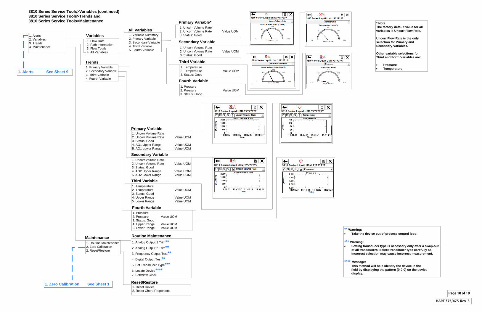
Page 10 of 10
Variables
1. Flow Data2. Path Information3. Flow Totals4. All Variables
1. Alerts2. Variables3. Trends4. Maintenance
3810 Series Service Tools>Variables (continued)
3810 Series Service Tools>Trends and
3810 Series Service Tools>Maintenance
Trends
1. Primary Variable2. Secondary Variable3. Third Variable4. Fourth Variable
Primary Variable
Secondary Variable
1. Uncorr Volume Rate2. Uncorr Volume Rate Value UOM3. Status: Good4. AO2 Upper Range Value UOM5. AO2 Lower Range Value UOM
Third Variable
Fourth Variable
1. Uncorr Volume Rate2. Uncorr Volume Rate Value UOM3. Status: Good4. AO1 Upper Range Value UOM5. AO1 Lower Range Value UOM
1. Temperature2. Temperature Value UOM3. Status: Good4. Upper Range Value UOM5. Lower Range Value UOM
1. Pressure2. Pressure Value UOM3. Status: Good4. Upper Range Value UOM5. Lower Range Value UOM
Maintenance
1. Routine Maintenance2. Zero Calibration2. Reset/Restore
All Variables1. Variable Summary2. Primary Variable3. Secondary Variable4. Third Variable5. Fourth Variable
Primary Variable*
1. Uncorr Volume Rate2. Uncorr Volume Rate Value UOM3. Status: Good
Secondary Variable
Third Variable
1. Pressure2. Pressure Value UOM3. Status: Good
Fourth Variable
* Note
The factory default value for all
variables is Uncorr Flow Rate.
Uncorr Flow Rate is the only
selection for Primary and
Secondary Variables.
Other variable selections for
Third and Forth Variables are:
· Pressure
· Temperature
1. Uncorr Volume Rate2. Uncorr Volume Rate Value UOM3. Status: Good
HART 375/475 Rev 3
Routine Maintenance
1. Analog Output 1 Trim**
2. Analog Output 2 Trim**
3. Frequency Output Test**
4. Digital Output Test**
5. Set Transducer Type***
6. Locate Device****7. Set/View Clock
** Warning:
· Take the device out of process control loop.
*** Warning:
· Setting transducer type is necessary only after a swap-out
of all transducers. Select transducer type carefully as
incorrect selection may cause incorrect measurement.
**** Message:
This method will help identify the device in the
field by displaying the pattern (0-0-0) on the device
display.
1. Alerts See Sheet 9
Reset/Restore1. Reset Device2. Reset Chord Proportions
1. Temperature2. Temperature Value UOM3. Status: Good
1. Zero Calibration See Sheet 1
HART Field Device Specification 3810 Series Ultrasonic Meter Annex E. Revision history3-9000-762 Rev 3 January 2014
E
Annex E. Revision historyE.1 Document release
This is this initial release of the Field Device Specification Guide.
Document release 157
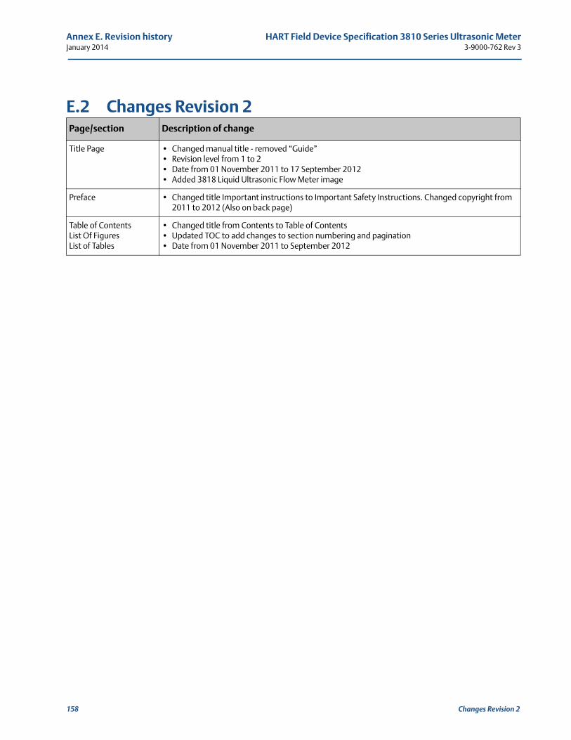
Annex E. Revision history HART Field Device Specification 3810 Series Ultrasonic MeterJanuary 2014 3-9000-762 Rev 3
E.2 Changes Revision 2Page/section Description of change
Title Page • Changed manual title - removed “Guide”• Revision level from 1 to 2• Date from 01 November 2011 to 17 September 2012• Added 3818 Liquid Ultrasonic Flow Meter image
Preface • Changed title Important instructions to Important Safety Instructions. Changed copyright from 2011 to 2012 (Also on back page)
Table of ContentsList Of Figures List of Tables
• Changed title from Contents to Table of Contents• Updated TOC to add changes to section numbering and pagination• Date from 01 November 2011 to September 2012
158 Changes Revision 2
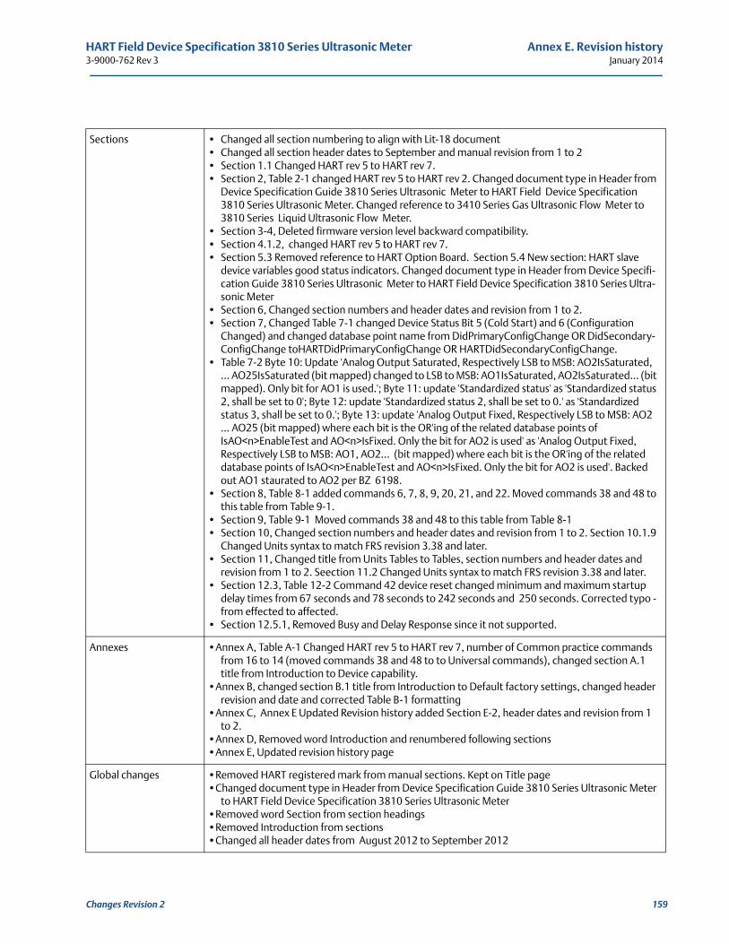
HART Field Device Specification 3810 Series Ultrasonic Meter Annex E. Revision history3-9000-762 Rev 3 January 2014
Sections • Changed all section numbering to align with Lit-18 document• Changed all section header dates to September and manual revision from 1 to 2• Section 1.1 Changed HART rev 5 to HART rev 7. • Section 2, Table 2-1 changed HART rev 5 to HART rev 2. Changed document type in Header from
Device Specification Guide 3810 Series Ultrasonic Meter to HART Field Device Specification 3810 Series Ultrasonic Meter. Changed reference to 3410 Series Gas Ultrasonic Flow Meter to 3810 Series Liquid Ultrasonic Flow Meter.
• Section 3-4, Deleted firmware version level backward compatibility. • Section 4.1.2, changed HART rev 5 to HART rev 7. • Section 5.3 Removed reference to HART Option Board. Section 5.4 New section: HART slave
device variables good status indicators. Changed document type in Header from Device Specifi-cation Guide 3810 Series Ultrasonic Meter to HART Field Device Specification 3810 Series Ultra-sonic Meter
• Section 6, Changed section numbers and header dates and revision from 1 to 2.• Section 7, Changed Table 7-1 changed Device Status Bit 5 (Cold Start) and 6 (Configuration
Changed) and changed database point name from DidPrimaryConfigChange OR DidSecondary-ConfigChange toHARTDidPrimaryConfigChange OR HARTDidSecondaryConfigChange.
• Table 7-2 Byte 10: Update 'Analog Output Saturated, Respectively LSB to MSB: AO2IsSaturated, … AO25IsSaturated (bit mapped) changed to LSB to MSB: AO1IsSaturated, AO2IsSaturated… (bit mapped). Only bit for AO1 is used.'; Byte 11: update 'Standardized status' as 'Standardized status 2, shall be set to 0'; Byte 12: update 'Standardized status 2, shall be set to 0.' as 'Standardized status 3, shall be set to 0.'; Byte 13: update 'Analog Output Fixed, Respectively LSB to MSB: AO2 … AO25 (bit mapped) where each bit is the OR'ing of the related database points of IsAO<n>EnableTest and AO<n>IsFixed. Only the bit for AO2 is used' as 'Analog Output Fixed, Respectively LSB to MSB: AO1, AO2… (bit mapped) where each bit is the OR'ing of the related database points of IsAO<n>EnableTest and AO<n>IsFixed. Only the bit for AO2 is used'. Backed out AO1 staurated to AO2 per BZ 6198.
• Section 8, Table 8-1 added commands 6, 7, 8, 9, 20, 21, and 22. Moved commands 38 and 48 to this table from Table 9-1.
• Section 9, Table 9-1 Moved commands 38 and 48 to this table from Table 8-1• Section 10, Changed section numbers and header dates and revision from 1 to 2. Section 10.1.9
Changed Units syntax to match FRS revision 3.38 and later. • Section 11, Changed title from Units Tables to Tables, section numbers and header dates and
revision from 1 to 2. Seection 11.2 Changed Units syntax to match FRS revision 3.38 and later.• Section 12.3, Table 12-2 Command 42 device reset changed minimum and maximum startup
delay times from 67 seconds and 78 seconds to 242 seconds and 250 seconds. Corrected typo - from effected to affected.
• Section 12.5.1, Removed Busy and Delay Response since it not supported.
Annexes •Annex A, Table A-1 Changed HART rev 5 to HART rev 7, number of Common practice commands from 16 to 14 (moved commands 38 and 48 to to Universal commands), changed section A.1 title from Introduction to Device capability.
•Annex B, changed section B.1 title from Introduction to Default factory settings, changed header revision and date and corrected Table B-1 formatting
•Annex C, Annex E Updated Revision history added Section E-2, header dates and revision from 1 to 2.
•Annex D, Removed word Introduction and renumbered following sections•Annex E, Updated revision history page
Global changes •Removed HART registered mark from manual sections. Kept on Title page•Changed document type in Header from Device Specification Guide 3810 Series Ultrasonic Meter
to HART Field Device Specification 3810 Series Ultrasonic Meter•Removed word Section from section headings•Removed Introduction from sections•Changed all header dates from August 2012 to September 2012
Changes Revision 2 159
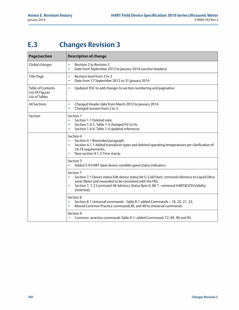
Annex E. Revision history HART Field Device Specification 3810 Series Ultrasonic MeterJanuary 2014 3-9000-762 Rev 3
E.3 Changes Revision 3
Page/section Description of change
Global changes • Revision 2 to Revision 3• Date from September 2012 to January 2014 (section headers)
Title Page • Revision level from 2 to 3• Date from 17 September 2012 to 31 January 2014
Table of ContentsList Of Figures List of Tables
• Updated TOC to add changes to section numbering and pagination
All Sections • Changed Header date from March 2012 to January 2014 • Changed revision from 2 to 3
Section Section 1• Section 1.1 Deleted note• Section 1.4.3, Table 1-3 changed HZ to Hz• Section 1.4.4, Table 1-4 updated references
Section 4• Section 4.1 Reworded paragraph.• Section 4.1.1 Added transducer types and deleted operating temperatures per clarification of
Lit-18 requirements.• New section 4.1.3 Time stamp
Section 5• Added 5.9 HART slave device variables good status indicators
Section 7• Section 7.1 Device status Edit device status bit 5: Cold Start, removed reference to Liquid Ultra-
sonic Meter and reworded to be consistent with the FRS.• Section 7. 7.2 Command 48 Advisory Status Byte 0, Bit 7 —removed HARTAO2SVValidity
(inverted).
Section 8• Section 8.1 Universal commands - Table 8-1 added Commands — 18, 20, 21, 22, • Moved Common Practice commands38, and 48 to Universal commands.
Section 9 • Common -practice commands Table 9-1: added Commands 72, 89, 90 and 95.
160 Changes Revision 3
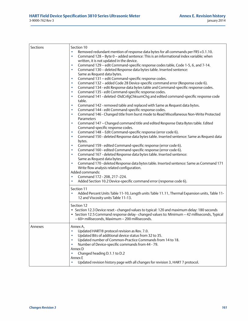
HART Field Device Specification 3810 Series Ultrasonic Meter Annex E. Revision history3-9000-762 Rev 3 January 2014
Sections Section 10• Removed redundant mention of response data bytes for all commands per FRS v3.1.10.• Command 128 — Byte 0 — added sentence: This is an informational index variable; when
written, it is not updated in the device.• Command 129 — edit Command-specific response codes table, Code 1-5, 6, and 7-14.• Command 130 — deleted Response data bytes table. Inserted sentence:
Same as Request data bytes.• Command 131 — edit Command-specific response codes.• Command 132 — added Code 28 Device-specific command error (Response code 6).• Command 134 - edit Response data bytes table and Command-specific response codes.• Command 135 - edit Command-specific response codes.• Command 141 - deleted -DidCnfgChksumChg and edited command-specific response code
table.• Command 142 - removed table and replaced with Same as Request data bytes.• Command 144 - edit Command-specific response codes.• Command 146 - Changed title from burst mode to Read Miscellaneous Non-Write Protected
Parameters• Command 147 — Changed command title and edited Response Data Bytes table. Edited
Command-specific response codes.• Command 148 — Edit Command-specific response (error code 6).• Command 150 - deleted Response data bytes table. Inserted sentence: Same as Request data
bytes.• Command 159 - edited Command-specific response (error code 6).• Command 160 - edited Command-specific response (error code 6).• Command 167 - deleted Response data bytes table. Inserted sentence:
Same as Request data bytes.• Command 170 - deleted Response data bytes table. Inserted sentence: Same as Command 171
Write flow analysis related configuration.Added commands:• Command 172 - 208, 217 -224.• Added Section 10.2 Device-specific command error (response code 6).
Section 11• Added Percent Units Table 11-10, Length units Table 11.11, Thermal Expansion units, Table 11-
12 and Viscosity units Table 11-13.
Section 12• Section 12.3 Device reset - changed values to typical: 120 and maximum delay: 180 seconds• Section 12.5 Command response delay - changed values to: Minimum — 42 milliseconds, Typical
— 60> milliseconds, Maximum — 200 milliseconds.
Annexes Annex A,• Updated HART® protocol revision as Rev. 7.0.• Updated Bits of additional device status from 32 to 35.• Updated number of Common-Practice Commands from 14 to 18. • Number of Device-specific commands from 44 - 79.Annex D• Changed heading D.1.1 to D.2Annex E• Updated revision history page with all changes for revision 3, HART 7 protocol.
Changes Revision 3 161
Annex E. Revision history HART Field Device Specification 3810 Series Ultrasonic MeterJanuary 2014 3-9000-762 Rev 3
162 Changes Revision 3

P/N 3-9000-762Rev 32014
Daniel Measurement and Control, Inc. 11100 Brittmoore Park DriveHouston, TX 77041 USA
T+1 713-467-6000F+1 713-827-4805USA Toll Free 1 888-356-9001Daniel Measurement Services, Inc.T +1 713-827-6413www.Daniel.com
This product is a core component of the PlantWeb digital plant architecture.
Europe: Stirling, Scotland, UKT + 44-1786-433400Middle East: Africa: Dubai, UAET +971-4-811-8100Asia Pacific: SingaporeT +65-677-8211
© 2014 Daniel Measurement and Control, Inc., All rights reserved
The Emerson logo is a trademark and service mark of Emerson Electric Co. Daniel Measurement and Control, Inc. (Daniel) are Emerson Process Management business units. The Daniel name and logo are trademarks of Daniel Industries, Inc. The Senior, Junior, Simplex, MeterLink SeniorSonic, JuniorSonic, and DanPac are trademarks of Daniel Industries, Inc. All other trademarks are property of their respective owners.