Embed Size (px)
Citation preview
DAQ Systems and Instruments for Hx Performance Testing and Periodic
Monitoring
Hx Performance Testing• Graftel has an experienced staff of field technicians
who have been conducting ILRTs and SITs at nuclear plants world wide since 1998.
• Those tests are all performed using instrumentation and software designed and manufactured by Graftel for those specific applications
• Graftel has been conducting Hx performance testing since 2006
• Graftel has developed, manufactured and used new instrumentation systems and technology for heat exchanger testing and monitoring
• This presentation discusses these new systems and technology
QUALITY ASSURANCEQUALITY ASSURANCE
• Graftel’s QA program meets the requirements of 10CFR50 Appendix B, 10 CFR 50. Part 21 may be invoked.
• All calibrations are performed in compliance with both ANSI/NCSL Z540-1-1994 and ISO 17025-2005.
• Graftel is in the NUPIC database as supplier of Appendix B calibration services, safety related software and heat exchanger performance testing services

Graftel is Certified by L.A.B. as an Graftel is Certified by L.A.B. as an ISO/IEC 17025:2005 Compliant ISO/IEC 17025:2005 Compliant
Calibration LaboratoryCalibration Laboratory
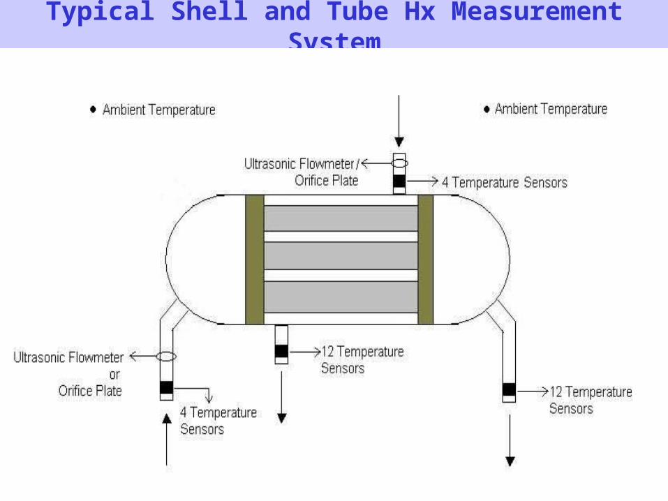
Typical Shell and Tube Hx Measurement System
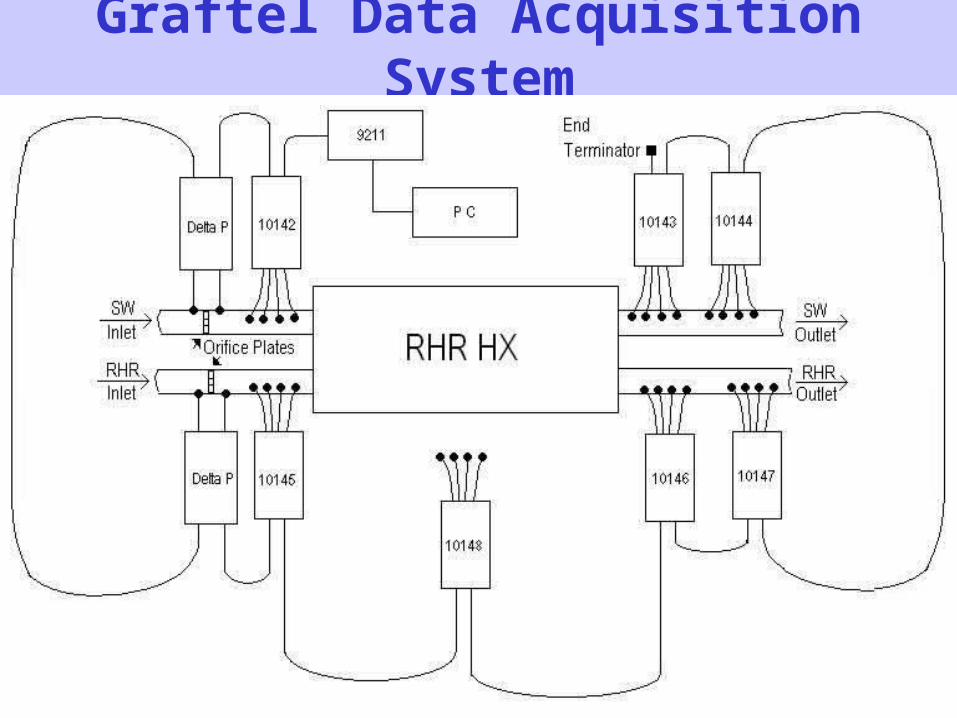
Graftel Data Acquisition System
•
System Advantages• Greatly reduced install & tear-down time
• Full end to end sensor calibration in lab, all sensors have digital outputs
• No loop checks required in field
• Improved accuracy and immunity to ambient signal noise
• No cable length effects upon accuracy
• Full sensor and probe interchangeability
Traditional Data Acquisition System
• In a traditional system, one cable connects each sensor to the DAS
• Our typical system would required 36 sensors, to be cabled to the DAS
• This includes two ambient temperature sensors, two current outputs from the flow meters and 32 temperature sensors on the pipes
• Set-up and field calibration check time is extensive
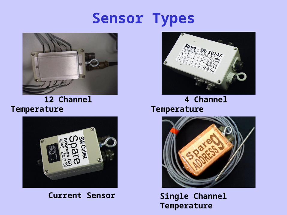
Sensor Types
12 Channel Temperature
4 Channel Temperature
Current Sensor Single Channel Temperature
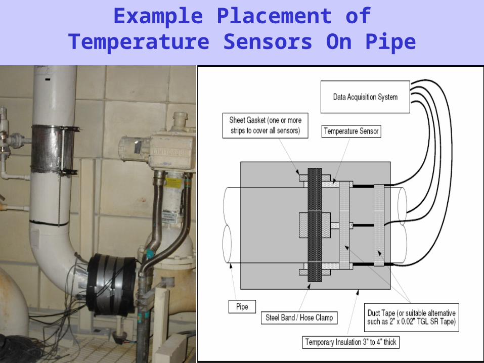
Example Placement of Temperature Sensors On Pipe
-
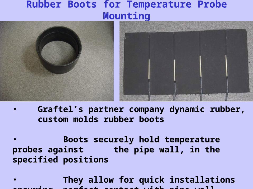
Rubber Boots for Temperature Probe Mounting
• Graftel’s partner company dynamic rubber, custom molds rubber boots
• Boots securely hold temperature probes against the pipe wall, in the specified positions
• They allow for quick installations ensuring perfect contact with pipe wall
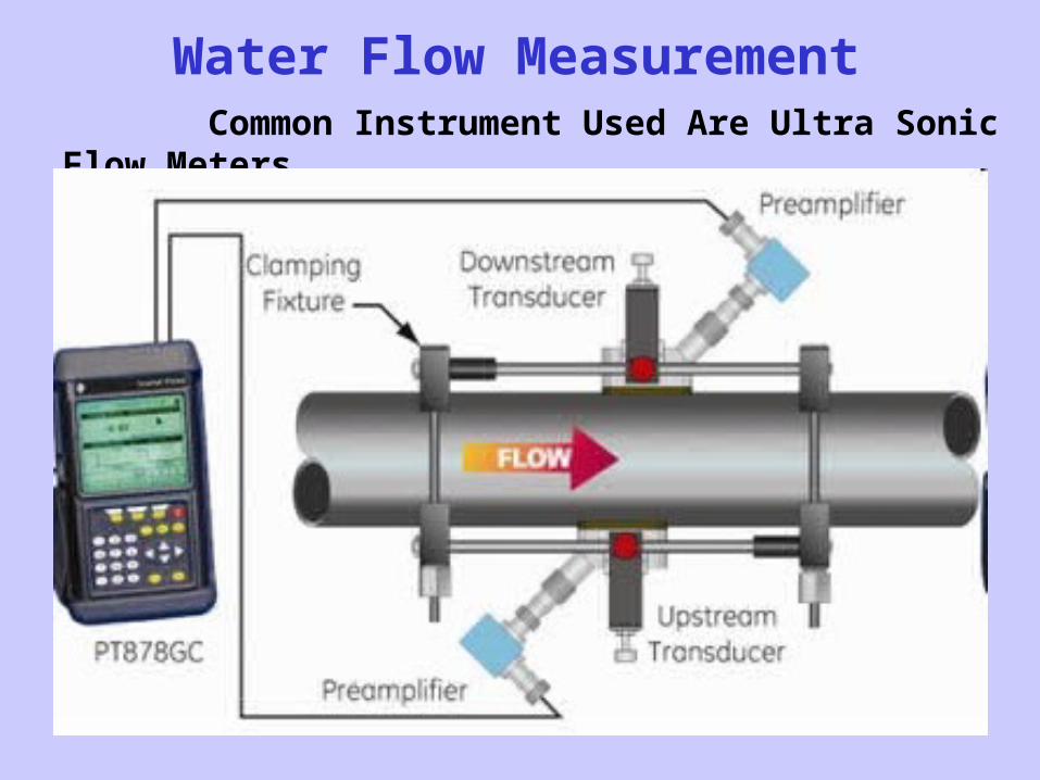
Water Flow Measurement Common Instrument Used Are Ultra Sonic Flow Meters
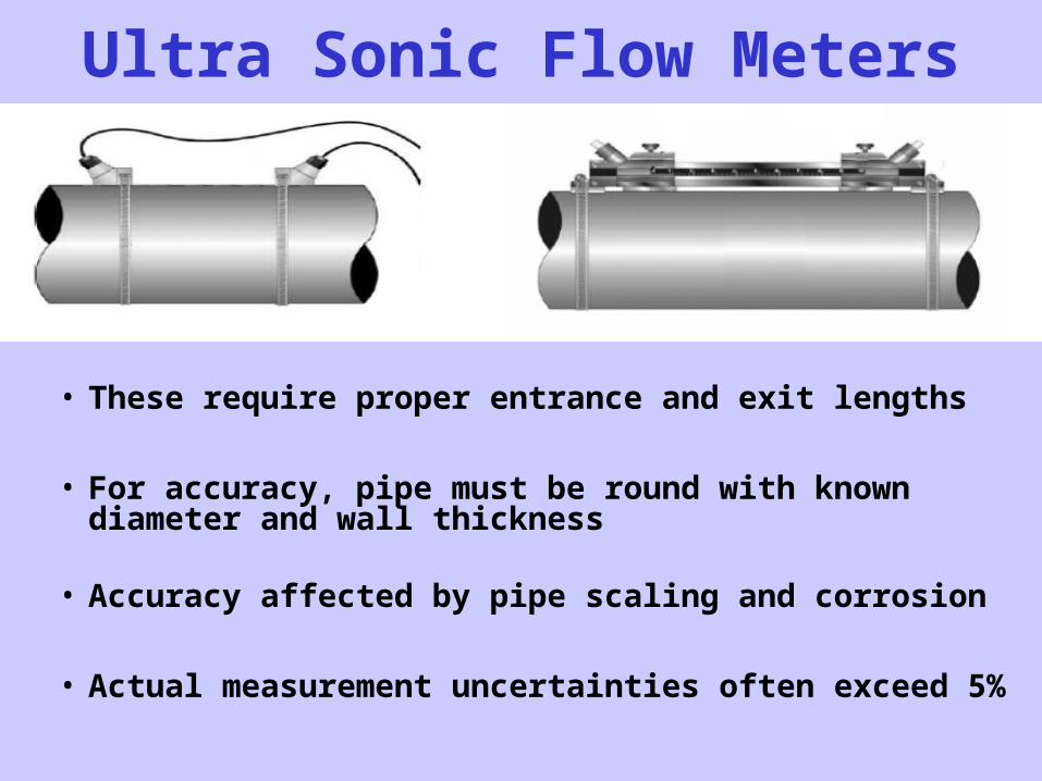
Ultra Sonic Flow Meters
• These require proper entrance and exit lengths
• For accuracy, pipe must be round with known diameter and wall thickness
• Accuracy affected by pipe scaling and corrosion
• Actual measurement uncertainties often exceed 5%
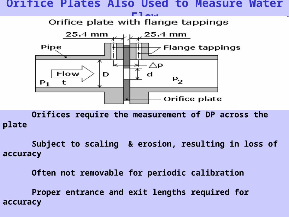
Orifice Plates Also Used to Measure Water Flow
Orifices require the measurement of DP across the plate
Subject to scaling & erosion, resulting in loss of accuracy
Often not removable for periodic calibration
Proper entrance and exit lengths required for accuracy
Actual measurement uncertainty may approach 5%
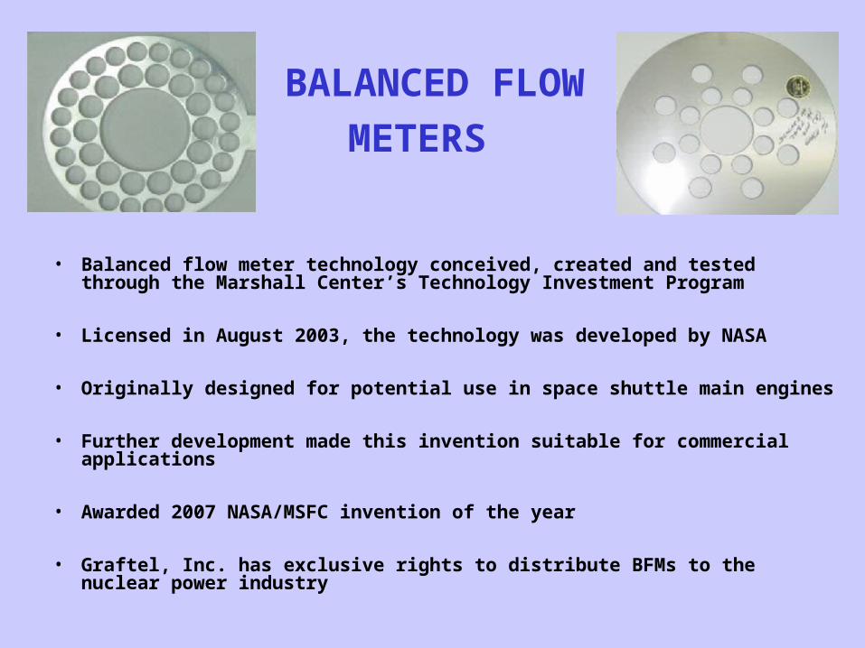
BALANCED FLOW
METERS
• Balanced flow meter technology conceived, created and tested through the Marshall Center’s Technology Investment Program
• Licensed in August 2003, the technology was developed by NASA
• Originally designed for potential use in space shuttle main engines
• Further development made this invention suitable for commercial applications
• Awarded 2007 NASA/MSFC invention of the year
• Graftel, Inc. has exclusive rights to distribute BFMs to the nuclear power industry
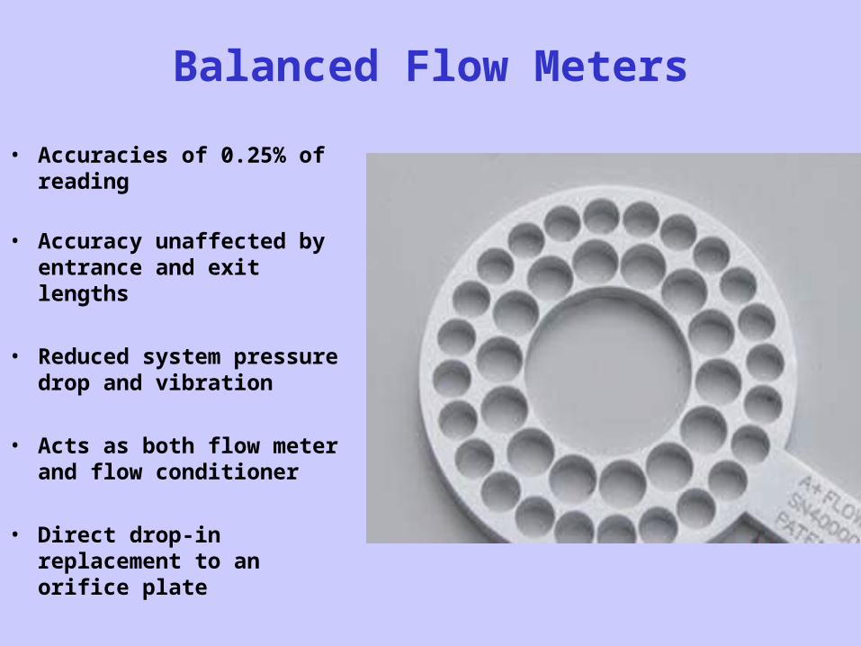
Balanced Flow Meters
• Accuracies of 0.25% of reading
• Accuracy unaffected by entrance and exit lengths
• Reduced system pressure drop and vibration
• Acts as both flow meter and flow conditioner
• Direct drop-in replacement to an orifice plate
BFM Advantages Over Orifice Plates
• Ten times improvement in accuracy
• 100% increase in pressure recovery
• No need for strait pipe runs before of after the plate
• Extreme resistance to Scaling
• 15 times reduction in noise energy/vibration
• Permanent pressure loss, accuracy and discharge coefficient comparable with a venturi meter
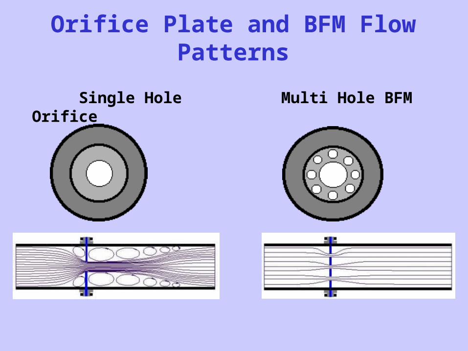
Orifice Plate and BFM Flow Patterns
Single Hole Orifice Multi Hole BFM
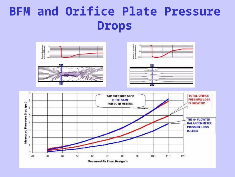
BFM and Orifice Plate Pressure Drops
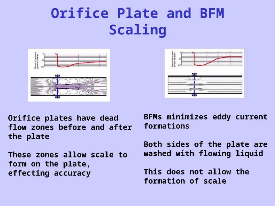
Orifice Plate and BFM Scaling
Orifice plates have dead flow zones before and after the plate
These zones allow scale to form on the plate, effecting accuracy
BFMs minimizes eddy current formations
Both sides of the plate are washed with flowing liquid
This does not allow theformation of scale

Balanced Flow Meter Designs
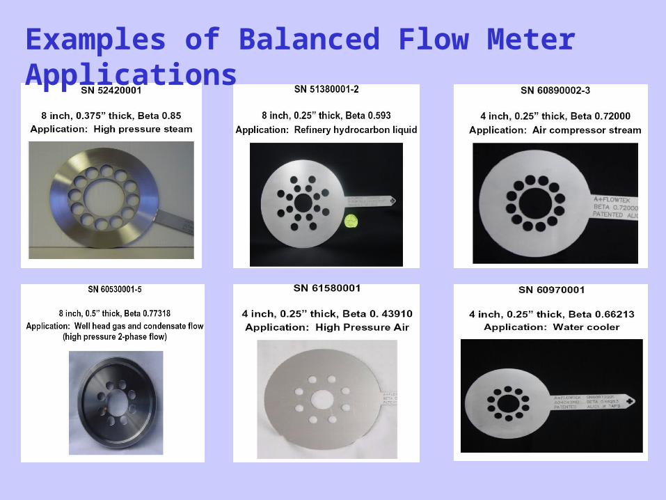
Examples of Balanced Flow Meter Applications
Data Collection Software
• Graftel collects data from the sensor system using a laptop running a software application that saves data in excel format
• The software validates raw data
• Checks individual data for stability
• Graphically shows measured temperature variations around a pipe’s perimeter
• Performs real time heat balances to validate test data while it is being collected
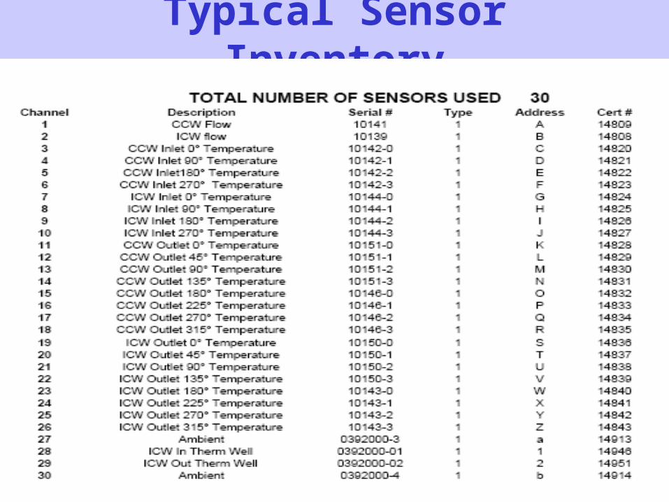
Typical Sensor Inventory
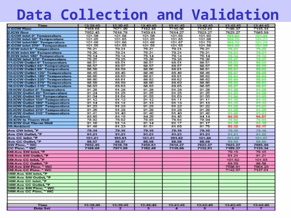
Data Collection and Validation
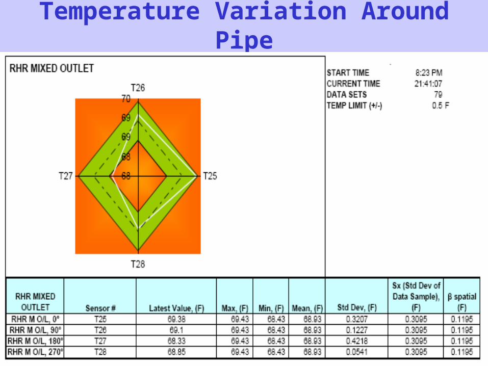
Temperature Variation Around Pipe
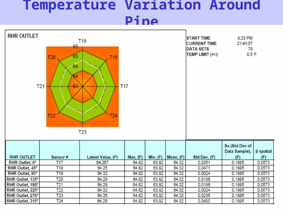
Temperature Variation Around Pipe
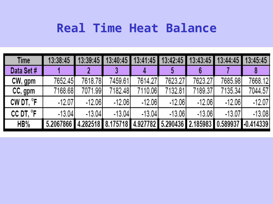
Real Time Heat Balance
Instrumented Balanced Flow Meters
• Balanced flow meters may be supplied with temperature probes inserted into holes cross-drilled into them from the edges
• This allows for the most accurate measurement of bulk average water temperature flowing though the pipe.
• Bulk temperature and flow rate may be measured simultaneously at the same point and time with great accuracy.
• This allows for extremely accurate measurement of heat flux past that point
Periodic Monitoring• Graftel uses a special glass encapsulated
thermistor for temperature measurement
• We use a process to burn-in sensors under heated conditions to minimize long term drift
• We have collected pre and post calibration on hundreds of these sensor for over 15 years
• This data may be used to justify 5 to 10 year recalibration intervals on sensors
Periodic Monitoring
• This long recalibration interval allows temperature sensors to be permanently mounted on the pipe parameter or inside the BFM
• Periodic monitoring may be performed by easily attaching a USB equipped data collect box to each pipe location
• Collected data is later downloaded and synchronized in the analysis software