Embed Size (px)
Citation preview

ServiceManual
Yokogawa Electric Corporation
DAQSTATION CX1000/CX2000
SM 04L31A01-01E2nd Edition
SM 04L31A01-01E
1SM 04L31A01-01E
Important Notice to the UserThis manual contains information for servicing YOKOGAWA’s DAQSTATION CX1000/
CX2000. Check the serial number to confirm that this is the correct service manual for
the instrument to be serviced. Do not use the wrong manual.
Before any maintenance and servicing, read all safety precautions carefully.
Only properly trained personnel may carry out the maintenance and servicing described
in this service manual.
Do not disassemble the instrument or its parts, unless otherwise clearly permitted by this
service manual.
Do not replace any part or assembly, unless otherwise clearly permitted by this service
manual.
In principle, Yokogawa Electric Corporation (YOKOGAWA) does not supply parts other
than those listed in the customer maintenance parts list in this service manual (mainly
modules and assemblies). Therefore if an assembly fails, the user should replace the
whole assembly and not components within the assembly (see “Note”). If the user
attempts to repair the instrument by replacing individual components within the
assembly, YOKOGAWA assumes no responsibility for any consequences such as
defects in instrument accuracy, functionality, reliability, or user safety hazards.
YOKOGAWA does not offer more detailed maintenance and service information than
that contained in this service manual.
All reasonable efforts have been made to assure the accuracy of the content of this
service manual. However, there may still be errors such as clerical errors or omissions.
YOKOGAWA assumes no responsibility of any kind concerning the accuracy or contents
of this service manual, nor for the consequences of any errors.
All rights reserved. No part of this service manual may be reproduced in any form or by
any means without the express written prior permission of YOKOGAWA. The contents
of this manual are subject to change without notice.
NoteYOKOGAWA instruments have been designed in a way that the replacement of electronic
parts can be done on an assembly (module) basis by the user. YOKOGAWA instruments
have also been designed in a way that troubleshooting and replacement of any faulty
assembly can be done easily and quickly. Therefore, YOKOGAWA strongly recommends
replacing the entire assembly over replacing parts or components within the assembly. The
reasons are as follows:
• The instruments use high-performance microprocessors, large scale CMOS gate arrays,
and surface-mount components to provide state-of-the-art performance and functions.
• Repair of components can only be performed by specially trained and qualified
maintenance personnel with special highly-accurate tools, including costly ones.
• When taking the service life and cost of the instruments into consideration, the
replacement of assemblies offers the user the possibility to use YOKOGAWA instruments
more effectively and economically with a minimum in downtime.
• Zip is a trademark or registerd trademark of Iomega Corporation in the United States
and/or other countries.
• Adobe and Acrobat are trademarks of Adobe System incorporated.
Disk No. SM13
2nd Edition : August 2002 (YK)
All Rights Reserved, Copyright © 2002, Yokogawa Electric Corporation
2 SM 04L31A01-01E
IntroductionThis manual contains information for servicing YOKOGAWA’s DAQSTATION CX1000/
CX2000.
NoteThis is the second edition of the manual, dated August 2002.
WARNING
This service manual is to be used by properly trained personnel only.To avoid personal injury, do not perform any servicing unless you are
qualified to do so. Refer to the safety precautions prior to performingany service. Even if servicing is carried out according to this servicemanual, or by qualified personnel, YOKOGAWA assumes no
responsibility for any result occurring from this servicing.
Safety PrecautionsThe following general safety precautions must be taken during all phases of operation,
service, and repair of this instrument. Failure to comply with these precautions or with
specific WARNINGS given elsewhere in this manual violates safety standards of design,
manufacture, and intended use of the instrument.
Yokogawa Electric Corporation assumes no liability for the customer’s failure to comply
with these requirements.
WARNING
Use the Correct Power SupplyEnsure the source voltage matches the voltage of the power supply
before turning ON the power.
Use the Correct Power Cord and PlugTo prevent an electric shock or fire, be sure to use the power supplycord recommend by YOKOGAWA. The main power plug must be
plugged in an outlet with a protective grounding terminal. Do notinvalidate protection by using an extension cord without protectivegrounding.
Connect the Protective Grounding TerminalThe protective grounding terminal must be connected to ground toprevent an electric shock before turning ON the power.
Do Not Impair the of Protective GroundingNever cut off the internal or external protective grounding wire ordisconnect the wiring of the protective grounding terminal. Doing socreates a potential shock hazard.
Do Not Operate with Defective Protective GroundingDo not operate the instrument if you suspect the protective groundingmight be defective.

3SM 04L31A01-01E
Do Not Operate Near Flammable MaterialsDo not operate the instrument in the presence of flammable liquids or
vapors. Operation of any electrical instrument in such an environmentconstitutes a safety hazard.
Do Not Remove Any CoversThere are some areas components inside the instrument containinghigh voltage. Do not remove any cover, if the power supply isconnected. The cover should be removed by qualified personnel only.
Ground the Instrument before Making External ConnectionsConnect the protective grounding before connecting the instrument to ameasurement or control unit.
Firnish a switch (double-pole type) to separate the CX2000 from themain power supply in the power supply line. In addition, make sureto indicate that the switch is a power control for the CX2000 on theswitch.
Switch SpecificationsSteady-state current ranting:1 A or more, inrush current rating:60 A or moreConnect a fuse between 2 A and 15 A in the power supply line.
Safety Symbols Used on Equipment and in Manuals
To avoid injury, death of personnel or damage to the
instrument, the operator must refer to an explanation in the
user’s manual.
High temperature. To avoid injury caused by hot surfaces,
the operator must not touch the heatsink.
Protective grounding terminal, to protect against electrical
shock.
This symbol indicates that the terminal must be connected
to ground before operation of equipment.
This symbol represents a functional grounding terminal.
Such terminals should not be used as a protective
grounding terminal.
WARNING A WARNING sign calls attention to a procedure, practice, or
condition, that could result in the injury or death of personnel
if not correctly performed or adhered to.
CAUTION A CAUTION sign calls attention to a procedure, practice, or
condition, that could result in damage to or the destruction
of part of the instrument if not correctly performed or
adhered to.
4 SM 04L31A01-01E
Overview of This Manual
This manual is meant to be used by qualified personnel only. Make sure to read the
safety precautions at the beginning of this manual as well as the warnings and cautions
contained in the chapters relevant to any servicing you may be carrying out.
This manual contains the following chapters.
1 Principles of Operation
Provides an introduction and safety considerations.
2 Testing
Explains the tests for checking the performance of the instrument.
3 Adjustments
Explains the adjustments which can be performed by users.
4 Replacing Parts
Describes maintenance which can be performed by users.
5 Troubleshooting
Presents procedures for troubleshooting and how to proceed in case parts need to be
replaced.
6 Schematic Diagram
Provides a system configuration diagram.
7 Customer Maintenance Parts List
Contains exploded views and a list of replaceable parts.
8 Procedures for Disassembly (CX1000)
Lists the steps required to remove parts from the instrument.
Specifications are not included in this manual. For specifications, refer to
IM 04L31A01-01E or IM 04L31A01-03E.
5SM 04L31A01-01E
1
2
3
4
5
6
7
8
Contents
Important Notice to the User ............................................................................................... 1
Introduction ......................................................................................................................... 2
Safety Precautions .............................................................................................................. 2
Safety Symbols Used on Equipment and in Manuals ......................................................... 3
Overview of This Manual .................................................................................................... 4
Chapter 1 Principles of Operation1.1 Block Diagram of the CX1000/CX2000 ............................................................................ 1-1
1.2 Input Section .................................................................................................................... 1-2
Chapter 2 Testing2.1 Overview of Tests ............................................................................................................. 2-1
2.2 Test Procedures ............................................................................................................... 2-3
2.3 CTRL Module Assembly Tests ....................................................................................... 2-10
2.4 DIO Module Assembly Test ............................................................................................ 2-11
Chapter 3 Adjustments3.1 Calibration of the Measuring Instrument’s Input ............................................................... 3-1
3.2 Control Output Calibration ............................................................................................... 3-6
Chapter 4 Replacing Parts4.1 Replacement of the Control Output Terminal Block (Module) .......................................... 4-1
Chapter 5 Troubleshooting5.1 Procedure ........................................................................................................................ 5-1
5.2 Flow Chart ........................................................................................................................ 5-2
5.3 Troubleshooting Checklist ................................................................................................ 5-3
Chapter 6 Schematic Diagram6.1 CX1000 Schematic Diagram ............................................................................................ 6-1
6.2 CX2000 Schematic Diagram ............................................................................................ 6-2
Chapter 7 Customer Maintenance Parts List7.1 CX1000 Customer Maintenance Parts List ...................................................................... 7-1
7.2 CX1000 Standard Accessories ........................................................................................ 7-8
7.3 CX2000 Customer Maintenance Parts List ...................................................................... 7-9
7.4 CX2000 Standard Accessories ...................................................................................... 7-16
Chapter 8 Procedures for Disassembly (CX1000)8.1 Removing the Bezel ......................................................................................................... 8-1
8.2 Removing the Board Assemblies and the Drive ............................................................... 8-4
8.3 Removing the Keyboard .................................................................................................. 8-6
8.4 Replacing the Backlight ................................................................................................... 8-8
8.5 Removing the Terminal Assembly .................................................................................. 8-10

1-1IM 04L31A01-01E
Prin
ciples o
f Op
eration
1
Chapter 1 Principles of Operation
1.1 Block Diagram of the CX1000/CX2000
Block Diagram of the CX1000
Data storage functionsControl/Measurement Input section
Calculation function
Measurement Alarm function
Communication function
(optional)
Input terminal
Scanner assembly
A/D assembly
CPU
External storage
Internal memory
Display unit
Remote function
Measurement Alarm Relay (optional)
Control Output section
Control Output
Contact Input
Contact Output
Control Alarm function
Block Diagram of the CX2000
Data storage functionsMeasurement Input section
Calculation function
Measurement Alarm function
Communication function
(optional)
Input terminal
Scanner assembly
A/D assembly
CPU
External storage
Internal memory
Display unit
Remote function
Measurement Alarm Relay (optional)
Control Input section
Input terminal
Scanner assembly
A/D assembly
Control Output section
Control Output
Contact Input
Contact Output
Transmitter power supply (optional)
Control - purpose DIO (optional)
VGA out function (optional)
Control Alarm function
Refer for details see schematic diagram page 6-1 and 6-2.

1-2 IM 04L31A01-01E
1.2 Input Section
A/D AssemblyThe A/D assembly has items such as a programmable gain amp, voltage reference,
PWM modulator, current source for RTD measurements, differential amp, voltage sourcefor RJC, serial parallel converter, control logic, and an occurred scanner SSR controlsignal.
The A/D assembly uses a sinewave oscillating type self-resonant switching power supply(DC/DC converter), and noise filtering is achieved by signal integration.
The A/D assembly detects the frequency of the power while it is ON and the integratedtime becomes 20 ms or 16.67 ms. Therefore it carries a very high rate of noise rejectionfor the power frequency (in auto mode).
In case the power frequency of the instrument and of the measured object are different,the appropriate integrated time is manually selectable. In case of the CX2000, the
selection of 100 ms for 50/60 Hz is also available. A 16 bit resolution is achievedregardless of the integrated time.
Input TerminalThe internal printboard is isothermal because a print board with a metal core is beingused. Therefore, stable reference junction compensation is realized.
Scanner AssemblyAn in-house SSR (solid state relay) is being used for the scanner. The SSR, having asemiconductor switch, has a withstand voltage as high as 1500 V and a leakage currentof only 1 nA. For that reason, it has the following features.
• Semi-infinite life due to the absence of mechanical contacts• Silent operation• No occurrence of thermoelectric power.
On the other hand, compared to a mechanical relay, the SSR has, the disadvantage of abigger ON resistance and OFF capacity. As a result, RTD measurement and noise
resistance characteristics are affected. Regarding RTD measurements, a differentialamp was inserted into the previously mentioned analog circuit without increasing thenumber of parts, so that it would receive no influence from ON resistance.
For RTD measurements in Measurement input section there is generally no insulationbetween channels.For RTD measurements in Control input section there is generally insulation between
channels.
Data Storage FunctionsFor storing data, the CX1000/CX2000 has 1.2 MB of internal memory and is equippedwith a Zip drive, or an ATA flash memory card drive. The measured data can also besaved to external storage media such as floppy disks, Zip disks, and ATA flash memory
cards.
Display UnitThe CX has a 5.5-inch (CX1000) or 10.4-inch (CX2000) TFT color LCD on which it
displays the measured results (240 (vertical) × 320 (horizontal) pixels for the CX1000 or480 (vertical) × 640 (horizontal) pixels for the CX2000).

1-3IM 04L31A01-01E
Prin
ciples o
f Op
eration
1Calculation FunctionThe CX1000/CX2000 performs differential computation, linear scaling, and square roots
using a microprocessor on the CPU board.
Measurement Alarm FunctionThe following eight alarm types can be set.
High limit (H), low limit (L), differential high limit (h), differential low limit (l), rate-of-change on increase (R), rate-of-change on decrease (r), alarm delay upper limit alarm(T), or alarm delay lower limit alarm (t).
Control Alarm FunctionThe following nine alarm types can be set.
PV high-limit, PV low-limit, Deviation high-limit, Deviation low-limit, Deviation high & lowlimit, SP high-limit, SP low-limit, Output high-limit, Output low-limit
Other Functions• Communication Function:
Ethernet (standard)RS-232/RS-422A interface added (optional).
• Remote Function:The trigger, start/stop, time adjustment, and other functions can be controlledremotely (optional).
• Measurement Alarm Relay:Measurement alarm output and memory end/fail output (option for CX1006 andCX2000).
• Transmitter Power Supply:DC24 V output for transmitter (only CX2000’s optional).
• VGA Out Function (Option for CX2000 Only):The instrument's screen can be displayed on an external monitor via VGA output.
• Control - Purpose DIO (CX2000 Only):Contact input
Input for designated operations such as start/stop. Activate using a no-voltagecontact or open collector signal. This is a 12-point input.
Contact output
Control Alarm output consists of 12 points of transistor contact output.
Control Output SectionControl OutputThe following types are available for universal control output.• Current output (continuous PID control output)
Continuously output a current (analog signal) proportional to the calculated PID values.• Time proportional PID voltage pulse output
Output an ON/OFF signal, having a pulse width proportional to the time, as a voltage
per the calculated PID values.• On/Off control relay contact output
• Output an ON/OFF signal, having a pulse width proportional to the time, at a relay
contact point per the calculated PID values.• Output an ON/OFF signal to a relay contact point corresponding to the sign (+/–) of
the deviation in the measured value from the specified target value.
Contact InputInput for designated operations such as start/stop. Activate using a no-voltage contactor open collector signal.
Contact OutputControl Alarm output consists of relay contact output and transistor contact output.
1.2 Input Section

2-1SM 04L31A01-01E
Testin
g
2
Chapter 2 Testing
2.1 Overview of Tests
The following describes general testing procedures for DAQSTATION CX1000/CX2000series instruments. For tests on specific modules or assemblies, see sections 2.3 and
later.
Operating ConditionsAmbient Temperature: 23 ± 2°CRelative Humidity: 55 ± 20%
Test Instruments
Instrument Specifications
DC voltage generator Accuracy: 0.005% of setting + 1 mV
DMM Accuracy: 0.005% of rdg + 1 mV
Resistors Accuracy: 0.01% or better
Insulation tester 500 VDC
Withstanding voltage tester AC 1 to 3 kV, 500 VDC
External monitor (for test of /D5 option) VGA monitor (H: 33.3 kHz, V: 60.168 Hz)
Oscilloscope 200 kS/s or more, isolated input
Thermostatic chamber ZC-114 (Coper Electronics Co., Ltd.) or equivalent
Testing ConditionsThe tests cover all included A/D converters.
The unit's analog input is in analog multiplexer format.
For the CX1000, channel group 1–6 of the measurement input section and channel
group 7–11 of the control input section are each assigned to one A/D converter. For the
CX2000, channel groups 1–5 and 6–10 of the control input section (slot 1) and channel
groups 1–10 and 11-20 of the measurement input section (slots 2 and 3) are each
assigned to one A/D converter.
Therefore, except for when specifying inputs linked to the same A/D converter, only one arbitrary
channel within a group need be tested (for example, not channels 1—5 but only channel 1).
2-2 SM 04L31A01-01E
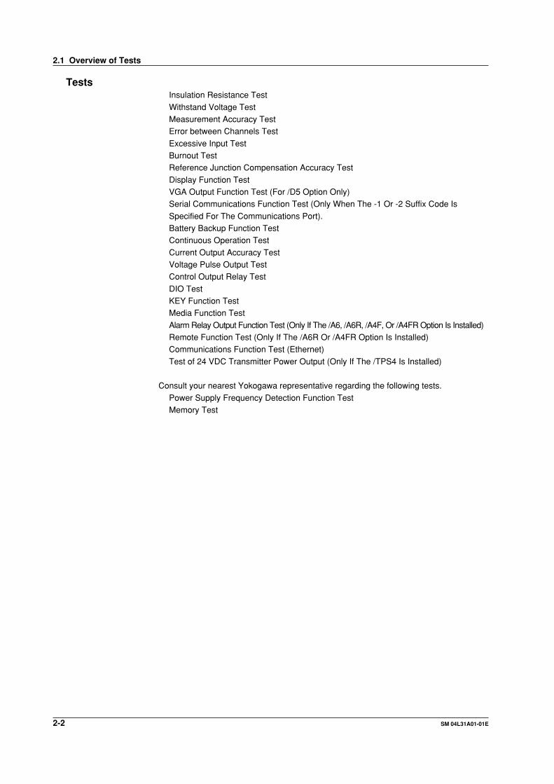
TestsInsulation Resistance Test
Withstand Voltage TestMeasurement Accuracy TestError between Channels Test
Excessive Input TestBurnout TestReference Junction Compensation Accuracy Test
Display Function TestVGA Output Function Test (For /D5 Option Only)Serial Communications Function Test (Only When The -1 Or -2 Suffix Code Is
Specified For The Communications Port).Battery Backup Function TestContinuous Operation Test
Current Output Accuracy TestVoltage Pulse Output TestControl Output Relay Test
DIO TestKEY Function TestMedia Function Test
Alarm Relay Output Function Test (Only If The /A6, /A6R, /A4F, Or /A4FR Option Is Installed)Remote Function Test (Only If The /A6R Or /A4FR Option Is Installed)Communications Function Test (Ethernet)
Test of 24 VDC Transmitter Power Output (Only If The /TPS4 Is Installed)
Consult your nearest Yokogawa representative regarding the following tests.
Power Supply Frequency Detection Function TestMemory Test
2.1 Overview of Tests

2-3SM 04L31A01-01E
Testin
g
2
2.2 Test Procedures
Insulation Resistance TestPerform this test using a DC 500 V insulation resistance meter and confirm that the
results meet the criteria below.
Terminals Reference Values Notes
Power terminal to earth terminal 100 MΩ or higher Short all channels prior to testMeasurement input terminal toearth terminalControl input terminal to earthterminal
RS-422-A/485 SG terminal to 100 MΩ or higher Test only if the basicRS-422-A/485 FG terminal specification code for the
communications port is -2.
Ethernet input/output terminal 100 MΩ or higher Short all terminals prior to testto earth terminal
Withstand Voltage TestPerform the test using a withstanding voltage tester and confirm that the results meet thecriteria below, and that the instrument does not malfunction.
Terminal Reference Values
AC power terminal to earth terminal* Leakage current of 10 mA or less at 1.5 kV AC for 1 minute
DC power terminal to earth terminal (/P1)* Leakage current of 10 mA or less at 0.5 kV AC for 1 minute
Measurement input terminal to earth terminal† Leakage current of 2 mA or less at 1.5 kV AC for 1 minute
Control input terminal to earth terminal† Leakage current of 2 mA or less at 1.5 kV AC for 1 minute
Between measuring input terminals‡ Leakage current of 1 mA or less at 1 kV AC for 1 minute
Between control input terminals‡ Leakage current of 1 mA or less at 1 kV AC for 1 minute
Current and voltage pulse to earth terminal§ Leakage current of 2 mA or less at 1 kV AC for 1 minute
Control relay terminal to earth terminal Leakage current of 2 mA or less at 1.5 kV AC for 1 minute(2, 4, and 6 loop models)||
DO relay terminal to earth terminal Leakage current of 2 mA or less at 1.5 kV AC for 1 minute(2, 4, and 6 loop models)#
DO(Tr) terminal to earth terminal Leakage current of 2 mA or less at 0.5 kV AC for 1 minute(2, 4, and 6 loop models or /CST1)**
D1 terminal to earth terminal Leakage current of 2 mA or less at 0.5 kV AC for 1 minute(2, 4, and 6 loop models or /CST1)††
Alarm relay terminal to earth terminal Leakage current of 2 mA or less at 1.5 kV AC for 1 minute(/A6, /A6R, /A4F, /A4FR)‡‡
Remote terminal to earth terminal (/A6R, /A4FR)§§ Leakage current of 2 mA or less at 0.5 kV AC for 1 minute
24 V transmitter power supply output to earth terminal Leakage current of 10 mA or less at 0.5 kV AC for 1 minute(/TPS4)||||
* Short L and N (or +/– with the /P1 option)
† Short all channels
‡ Short the + and – input terminals (except for the RTD b terminal)
Short the even and odd channels (for example, short channels 1-3-5 and 2-4-6 on the CX1000 or channels 1-3-
5-7-9 and channels 2-4-6-8-10 for the CX2000), and test the withstanding voltage between them.
§ Short mA, PULS, and C.
|| Short NO, NC, and C on CTRL OUT.
# Short 1NO, 1C, and 2NO on DO.
** Short DO3—DO6 and C.
†† Short all DI terminals.
‡‡ Short all alarm relay terminals.
§§ Short all remote terminals.
|||| Short all transmitter power supply output terminals (+/–).
2-4 SM 04L31A01-01E
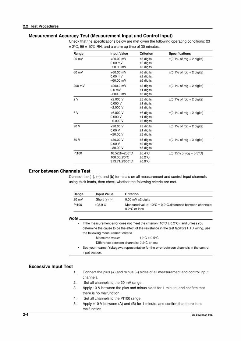
Measurement Accuracy Test (Measurement Input and Control Input)Check that the specifications below are met given the following operating conditions: 23
± 2°C, 55 ± 10% RH, and a warm up time of 30 minutes.
Range Input Value Criterion Specifications
20 mV +20.00 mV ±3 digits ±(0.1% of rdg + 2 digits)0.00 mV ±2 digits–20.00 mV ±3 digits
60 mV +60.00 mV ±6 digits ±(0.1% of rdg + 2 digits)0.00 mV ±2 digits–60.00 mV ±6 digits
200 mV +200.0 mV ±3 digits ±(0.1% of rdg + 2 digits)0.0 mV ±1 digits–200.0 mV ±3 digits
2 V +2.000 V ±3 digits ±(0.1% of rdg + 2 digits)0.000 V ±1 digits–2.000 V ±3 digits
6 V +6.000 V ±6 digits ±(0.1% of rdg + 2 digits)0.000 V ±1 digits–6.000 V ±6 digits
20 V +20.00 V ±3 digits ±(0.1% of rdg + 2 digits)0.00 V ±1 digits–20.00 V ±3 digits
50 V +30.00 V ±5 digits ±(0.1% of rdg + 3 digits)0.00 V ±2 digits–30.00 V ±5 digits
Pt100 18.52Ω/–200°C ±0.4°C ±(0.15% of rdg + 0.3°C)100.00Ω/0°C ±0.2°C313.71Ω/600°C ±0.9°C
Error between Channels TestConnect the (+), (–), and (b) terminals on all measurement and control input channelsusing thick leads, then check whether the following criteria are met.
Range Input Value Criterion
20 mV Short (+) (–) 0.00 mV ±2 digits
Pt100 103.9 Ω Measured value: 10°C ± 0.2°C,difference between channels:0.2°C or less
Note• If the measurement error does not meet the criterion (10°C ± 0.2°C), and unless you
determine the cause to be the effect of the resistance in the test facility's RTD wiring, use
the following measurement criteria.
Measured value: 10°C ± 0.5°CDifference between channels: 0.2°C or less
• See your nearest Yokogawa representative for the error between channels in the control
input section.
Excessive Input Test1. Connect the plus (+) and minus (–) sides of all measurement and control input
channels.2. Set all channels to the 20 mV range.
3. Apply 10 V between the plus and minus sides for 1 minute, and confirm thatthere is no malfunction.
4. Set all channels to the Pt100 range.
5. Apply ±10 V between (A) and (B) for 1 minute, and confirm that there is nomalfunction.
2.2 Test Procedures
2-5SM 04L31A01-01E
Testin
g
2
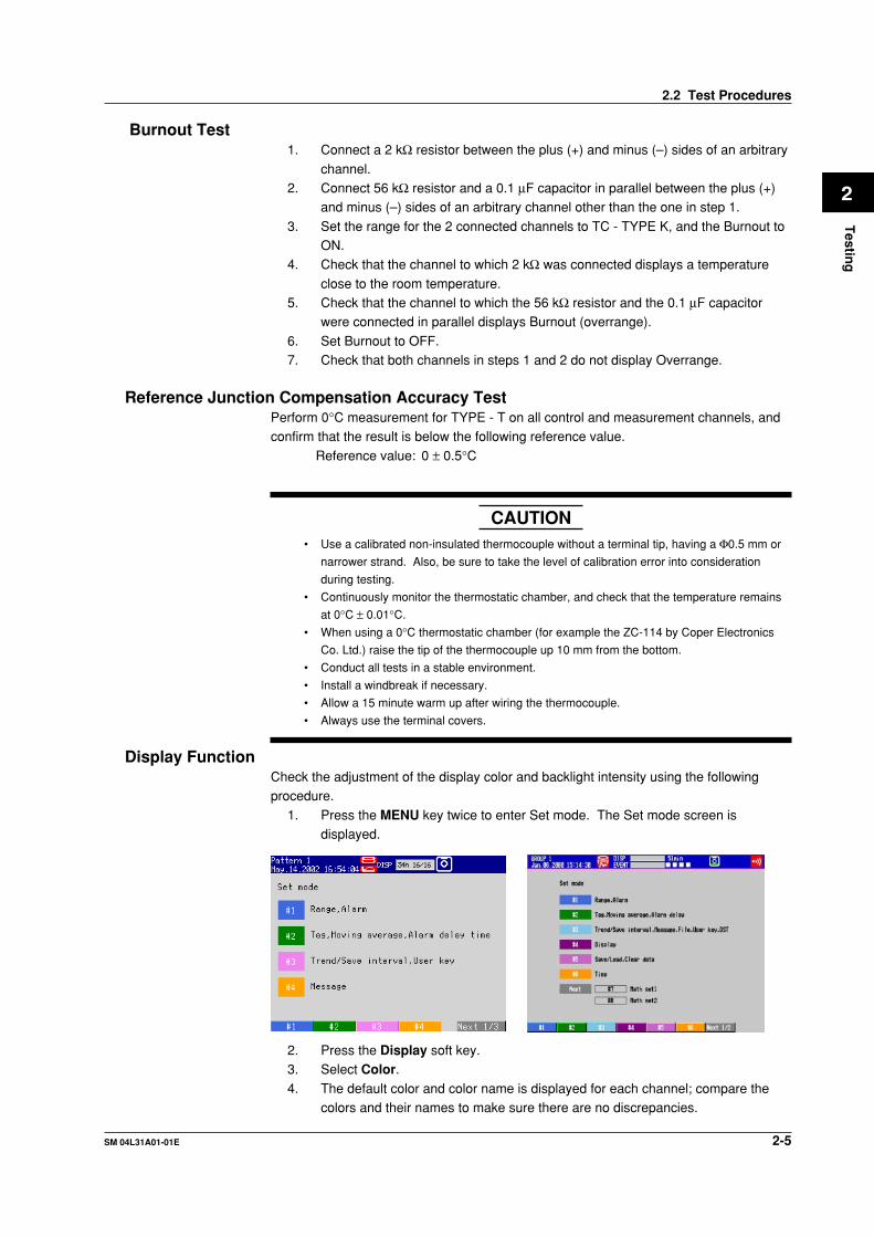
Burnout Test1. Connect a 2 kΩ resistor between the plus (+) and minus (–) sides of an arbitrary
channel.2. Connect 56 kΩ resistor and a 0.1 µF capacitor in parallel between the plus (+)
and minus (–) sides of an arbitrary channel other than the one in step 1.
3. Set the range for the 2 connected channels to TC - TYPE K, and the Burnout toON.
4. Check that the channel to which 2 kΩ was connected displays a temperature
close to the room temperature.5. Check that the channel to which the 56 kΩ resistor and the 0.1 µF capacitor
were connected in parallel displays Burnout (overrange).
6. Set Burnout to OFF.7. Check that both channels in steps 1 and 2 do not display Overrange.
Reference Junction Compensation Accuracy TestPerform 0°C measurement for TYPE - T on all control and measurement channels, andconfirm that the result is below the following reference value.
Reference value: 0 ± 0.5°C
CAUTION• Use a calibrated non-insulated thermocouple without a terminal tip, having a Φ0.5 mm or
narrower strand. Also, be sure to take the level of calibration error into consideration
during testing.
• Continuously monitor the thermostatic chamber, and check that the temperature remains
at 0°C ± 0.01°C.
• When using a 0°C thermostatic chamber (for example the ZC-114 by Coper Electronics
Co. Ltd.) raise the tip of the thermocouple up 10 mm from the bottom.
• Conduct all tests in a stable environment.
• Install a windbreak if necessary.
• Allow a 15 minute warm up after wiring the thermocouple.
• Always use the terminal covers.
Display FunctionCheck the adjustment of the display color and backlight intensity using the followingprocedure.
1. Press the MENU key twice to enter Set mode. The Set mode screen isdisplayed.
2. Press the Display soft key.3. Select Color.4. The default color and color name is displayed for each channel; compare the
colors and their names to make sure there are no discrepancies.
2.2 Test Procedures

2-6 SM 04L31A01-01E
5. Press ESC to return to the previous screen.6. Press the View, Direction, LCD soft key.
7. Move the cursor to Brightness.8. For the CX1000, select 1 through 8 and confirm that each brightness level is
brighter than the one before it. For the CX2000, select 1 through 4 and confirm
that each brightness level is brighter than the one before it.9. During other phases of testing as well, always be checking for any abnormalities
in the display that may appear.
10. Set Brightness to 3.
VGA Output Function Test (for the /D5 Option Only)Connect a VGA monitor to the VGA output terminal on the back of the CX2000, then lookat the screen to check the VGA output. Perform steps 1—10 above for the displayfunction and check the results.
Serial Communications Function Test (Only If the -1 or -2 Suffix Code is Specified forthe Communications Port)
During this test, actual communications are performed to check whether the RS-232,RS-422A/485, or other functions are operating properly. However, if you used serialcommunications successfully to carry out other tests, you don't need to perform this test.
Perform the tests using the procedure below.1. Connect a cable between the PC and the CX1000/CX2000.
If communications cannot be carried out via RS-422A/485, use an RS-232 adapter.
2. Send an arbitrary command from the PC using application software for CX1000/CX2000 series instruments or other software, and confirm that the expected resultoccurs.
Battery Backup Function Test1. While the CX1000/CX2000 is ON, set the date and time (see section 3.3,
“Setting the Date and Time” in manual IM 04L31A01-01E or IM 04L31A01-03E).2. Turn the power OFF.3. Wait at least one minute, then turn the power back ON.
4. Confirm that the date and time set in step 1 are correct.
Continuous Operation Test1. Enter the following settings.
• Enter AUTO SAVE to the media (see section 9.1 of the manual, IM 04L31A01-01).
• Set all channels to a range of 20 V (see section 4.6 of the manual, IM 04L31A01-01).
• Set input to open.
• Set display type to waveform display (see section 1.16 of the manual, IM 04L31A01-01).
2. Press the START key.
3. Run the instrument continuously for 24 hours or more.4. Press the STOP key.5. Check the following:
• That a data file was created in the MEDIA INFO screen (see section 4.6 ofthe manual, IM 04L31A01-01E).
• That there is no abnormal variation in the straight line waveform.
• That there is no other strange sound or odor coming from the instrument.
2.2 Test Procedures

2-7SM 04L31A01-01E
Testin
g
2
Current Output Accuracy1. Change the mode to setup and choose Control, Control action, and then Input
setting. Set the control mode to Single. Press the ESC key to return to thepreceding menu, and choose Output processing.
2. Set the type of control output to Current-output and analog output to 4-20 mAfor all the loops, save the settings, and change the mode to normal (the cycletime can be set freely).
3. Press the DISP/ENTER key and choose Control and then Control groups to
display the control display.4. Choose a loop number to measure with a blue arrow using the arrow keys.5. Press the MODE softkey, and change the operation mode to manual by
choosing MAN with the up and down arrow keys and pressing DISP/ENTER keyto confirm it.
6. Press the RUN/STP softkey, and start control operation by choosing RUN with
the up and down arrow keys and pressing DISP/ENTER key to confirm it.7. Press the OUT softkey. Set the output ratio to 0.0% and 100.0% with the up and
down arrow keys and measure each output current with an ammeter or the like.
Verify that the measured currents are within the ranges as shown in the tablebelow.
Output Ratio Reference Value Allowable Range
0.0% 4 mA 3.984 to 4.016 mA
100.0% 20 mA 19.984 to 20.016 mA
(Load condition: 250 Ω ±1%)
Voltage Pulse Output1. Choose Output processing by following the procedures in step 1 of “Current
Output Accuracy.”2. Set the type of control output to Voltage-pulse and the cycle time to 1 second
for all the loops, save the settings, and change the mode to normal (the type of
analog output can be set freely).3. Change the operation mode to manual and start control operation by following
the procedures of steps 5 and 6 of “Current Output Accuracy.”
4. Press the OUT softkey. Set the output ratio to 20.0% with the up and downarrow keys and observe the output voltage waveform on an oscilloscope or thelike. Verify that a rectangular waveform is displayed at a 1-second interval (0.2-
second high and 0.8-second low) and 12 V ± 5%.
Control Relay Output1. Choose Output processing by following the procedures in step 1 of “Current
Output Accuracy.”2. Set the type of control output to On/Off-control for all the loops, save the
settings, and change the mode to normal (the cycle time and type of analogoutput can be set freely).
3. Change the operation mode to manual and start control operation by following
the procedures of steps 5 and 6 of “Current Output Accuracy.”4. Press the OUT softkey. Set the output ratio to 0.0% and 100.0% with the up and
down arrow keys and verify that the relay outputs are as follows:
Output Ratio NO-C NC-C
0.0% Break Make
100.0% Make Break
2.2 Test Procedures
2-8 SM 04L31A01-01E
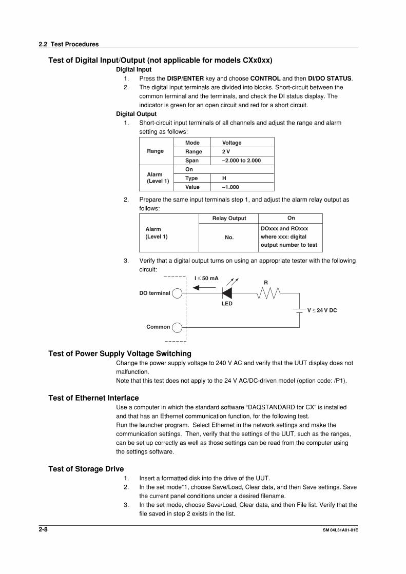
Test of Digital Input/Output (not applicable for models CXx0xx)Digital Input
1. Press the DISP/ENTER key and choose CONTROL and then DI/DO STATUS.2. The digital input terminals are divided into blocks. Short-circuit between the
common terminal and the terminals, and check the DI status display. The
indicator is green for an open circuit and red for a short circuit.Digital Output
1. Short-circuit input terminals of all channels and adjust the range and alarm
setting as follows:
Range
Alarm(Level 1)
Mode
Range
Span
On
Type
Value
Voltage
2 V
–2.000 to 2.000
H
–1.000
2. Prepare the same input terminals step 1, and adjust the alarm relay output asfollows:
Alarm(Level 1)
Relay Output On
No.
DOxxx and ROxxx
where xxx: digital
output number to test
3. Verify that a digital output turns on using an appropriate tester with the followingcircuit:
DO terminal
Common
LED
R
V ≤ 24 V DC
I ≤ 50 mA
Test of Power Supply Voltage SwitchingChange the power supply voltage to 240 V AC and verify that the UUT display does notmalfunction.Note that this test does not apply to the 24 V AC/DC-driven model (option code: /P1).
Test of Ethernet InterfaceUse a computer in which the standard software “DAQSTANDARD for CX” is installed
and that has an Ethernet communication function, for the following test.Run the launcher program. Select Ethernet in the network settings and make thecommunication settings. Then, verify that the settings of the UUT, such as the ranges,
can be set up correctly as well as those settings can be read from the computer usingthe settings software.
Test of Storage Drive1. Insert a formatted disk into the drive of the UUT.2. In the set mode*1, choose Save/Load, Clear data, and then Save settings. Save
the current panel conditions under a desired filename.3. In the set mode, choose Save/Load, Clear data, and then File list. Verify that the
file saved in step 2 exists in the list.
2.2 Test Procedures

2-9SM 04L31A01-01E
Testin
g
2
Test of Storage Drive1. Insert a formatted disk into the drive of the UUT.
2. In the set mode*1, choose Save/Load, Clear data, and then Save settings. Savethe current panel conditions under a desired filename.
3. In the set mode, choose Save/Load, Clear data, and then File list. Verify that the
file saved in step 2 exists in the list.
Test of Alarm Relay Contact Outputs (applicable to option codes /A6, /A6R, /A4F and /A4FR)
Insulation Resistance and Withstanding Voltage Tests
Item Measured Point Specification
Insulation resistance No less than 20 MΩ at 500 V DC
Withstanding voltage As above
Between relay output terminals and grounding terminal
Free from damage after applying 1500 V AC, 50/60 Hz for 1 minute (with breaking leakage current set to 2 mA)
Alarm Actions1. Prepare the same input terminals and settings as step 1 in “Digital Output”
(page 2-8), and also adjust the alarm relay output as follows:
Alarm(Level 1)
Relay Output On/off
No.
Ixxwhere xx: alarm output number to test
2. Verify that an alarm contact works as follows upon turning on/off the
corresponding relay output.
Terminals Normal Remarks
NO–C Break Where the output relay action is set to
normally de-energized (factory set)NC–C Make
During Alarm
Make
Break
Test of Remote Control (applicable to option codes /A6R and /A4FR)Insulation Resistance and Withstanding Voltage Tests
Item Measured Point Specification
Insulation resistance Between remote control terminals and grounding terminal
No less than 20 MΩ at 500 V DC
Withstanding voltage As above Free from damage after applying 500 V DC for 2 minute (with breaking leakage current set to 2 mA)
Remote Control ActionsAssign individual functions to 8 remote control inputs, then short-circuit each of those
inputs in turn and verify that the CX1000/CX2000 is controlled as specified.
Test of 24 VDC Transmitter Power Output (applicable to option code /TPS4)Test of Insuration Resistance and Withstanding Voltage
Withstanding voltage
Insulation resistance Between 24 VDC output terminals and
grounding terminal
As above
Between 24VDC output terminals
No less than 20 MΩ at 500 VDC
Free from damage after applying 500 VAC, 50/60 Hz for
1 minute (with breaking leakage current set to 10 mA)
Free from damage after applying 500 VAC, 50/60 Hz for
1 minute (with breaking leakage current set to 10 mA)
2.2 Test Procedures
2-10 SM 04L31A01-01E
2.3 CTRL Module Assembly Tests
This section describes the test procedure for CTRL MODULE ASSY (B8700CL,
B8700CM, B8700CN, and B8700FT) which is used on the CX2000. This test is notnecessary if you will perform the general tests in section 2.2. Perform this test on themodule by itself.
Test Instruments
Instrument Specifications
DC current meter Accuracy: 0.01% of rdg
Withstanding voltage tester AC 1 to 3 kV, 500 VDC
Oscilloscope 200 kS/s or more, isolated input
Resistor 250 Ω ±1%
Jig A measurement instrument having the same functions andcharacteristics as the CX2000 or CX1000.
Tests• Withstand Voltage Test
Consult your nearest Yokogawa representative regarding the following tests.• Output Accuracy Test• Voltage Pulse Output Test
• Control Relay Output Test• DI Test• DO Test
Testing EnvironmentAmbient temperature of 23±5°C, relative humidity of 55 ±20%
CAUTION• Before starting the test, allow the instrument to warm up for 30 minutes or more.• Make sure the module is installed in the CX1000/CX2000.
Test ProcedurePerform a withstand voltage test on the module installed in the CX1000/CX2000 at the
points listed below.
Test Points Reference Values
Current and voltage pulse output to earth terminal on Leakage current of 2 mA or less at 1 kV AC for 1 minutethe CX1000/CX2000*
Control relay terminal to CX1000/CX2000 earth terminal† Leakage current of 2 mA or less at 1.5 kV AC for 1 minute
DO relay terminal to CX1000/CX2000 earth terminal‡ Leakage current of 2 mA or less at 1.5 kV AC for 1 minute
DO (Tr) relay terminal to CX1000/CX2000 earth terminal§ Leakage current of 2 mA or less at 0.5 kV AC for 1 minute
DI terminal to CX1000/CX2000 earth terminal|| Leakage current of 2 mA or less at 0.5 kV AC for 1 minute* Short mA, PULS, and C.
† Short NO, NC, and C.
‡ Short NO and C.
§ Short DO3—6 and C.
|| Short all DIs.
2-11SM 04L31A01-01E
Testin
g
2
2.4 DIO Module Assembly Test
This section describes the test procedure for CTRL MODULE ASSY (B8700CY) which isused on the CX1000/CX2000. This test is not necessary if you perform the general tests
in section 2.2. Perform this test when testing the module by itself.
Test Instruments
Instrument Specifications
Withstanding voltage tester AC 1 to 3 kV, 500 VDC
Jig A measurement instrument having the same functions andcharacteristics as the CX1000/CX2000
Tests• Withstand Voltage Test
Consult your nearest Yokogawa representative regarding the following tests.• DI Test• DIO Test
Testing EnvironmentAmbient temperature of 23 ±5°C, relative humidity of 55 ±20%
CAUTION• The following assumes that the test will be performed with the module installed in
the CX1000/CX2000.• The test cannot be performed on models having no internal control loops with no
DIO module installed.
Test ProcedurePerform a withstand voltage test on the module installed in the CX1000/CX2000 at thepoints listed below.
Test Points Reference Values
DO terminal to CX1000/CX2000 earth terminal* Leakage current of 2 mA or less at 0.5 kV AC for 1 minute
DI terminal to CX1000/CX2000 earth terminal† Leakage current of 2 mA or less at 0.5 kV AC for 1 minute* Short DO1—12 and C.
† Short all DIs.

3-1SM 04L31A01-01E
Ad
justm
ents
3
Chapter 3 Adjustments
3.1 Calibration of the Measuring Instrument’s Input
Allow the instrument to warm up for at least 30 minutes prior to calibration.
Instruments for CalibrationDC voltage generator Accuracy: 0.005% of setting +1 µVResistor 100 Ω, 300 Ω (accuracy: 0.01% or less)
OverviewThe structure of the A/D converter in the CX2000 differs depending on the model.
Multiple channels (groups) share one A/D converter. All A/D converters must becalibrated, so calibration must be performed on each group.CX1000
Monitor
No. of Inputs for Measurement Total Number No. of No. of Group Meas. Interval of Channels CH/AD A/D
6ch 1s 6 6 1 (1—6)* Group: a classification for all channels that share a single A/D converter
Control (1st Slot)
Number of Internal Measurement Total Number No. of No. of GroupControl Loops interval of Channels CH/AD A/D
0 loops — 0 0 0 —
2 loops 250 mS 5 5 1 (1—5)
CX2000Control (1st Slot)
Number of Internal Measurement Total Number No. of No. of Group*Control Loops interval of Channels CH/AD A/D
0 loops — 0 0 0 —
2 loops 250 mS 5 5 1 (1—5)
4 or 6 loops 250 mS 10 5 2 (1—5) (6—10)* Group: a classification for all channels that share a single A/D converter
Monitor (2nd, 3rd Slot)
No. of Inputs for Measurement Total Number No. of No. of GroupMeas. Interval of Channels CH/AD A/D
10 ch 1s 10 10 1 (1—10)
20 ch 1s 20 10 2 (1—10) (11—20)
Ranges to Be Calibrated and Their Parameters
Range Zero Full Scale
20 mV 0 mV 20 mV
60 mV 0 mV 60 mV
200 mV 0 mV 200 mV
1 V 0 V 1V
2 V 0 V 2 V
6 V 0 V 6V
20 V 0 V 20 V
Pt100† 100 Ω 300 Ω† You must calibrate the 200 mV range before calibrating the RTD range.

3-2 SM 04L31A01-01E
Calibrating the Input RangeFor each group, input the zero and full scale for the input range to the channels below
and perform calibration.
CX1000• Voltage Range
Control
Number of Internal Group 2 (1—5ch)
Control Loops Zero Full Scale
0 loops — —
2 loops CH1* CH2** The expression channel is not used for control input, but for expediency the inputs are
referred to (from right to left) as CH1 and CH2 respectively.
Monitor
No. of Inputs for Meas. Group 1 (1—6ch)
Zero Full Scale Zero Full Scale
6ch CH1 CH2
• RTD RangeControl
Number of Internal Group 2 (1—5ch)
Control Loops 100 Ω 300 Ω
0 loops — —
2 loops CH1* CH2** The expression channel is not used for control input, but for expediency the inputs are
referred to (from right to left) as CH1 and CH2 respectively.
Monitor
No. of Measurement Group 1 (1—6ch)
Input Channels 100 Ω 300 Ω
6ch CH1 CH2
CX2000• Voltage Range
Control (1st Slot)
Number of Internal Group 1 Group 2
Control Loops Zero Full Scale Zero Full Scale
0 loops — — — —
2 loops CH1 CH2 — —
Loops 4,6 CH1 CH2 CH6 CH7
Monitor (2nd, 3rd Slot)
No. of Inputs for Meas. Group 1 Group 2
Zero Full Scale Zero Full Scale
10 ch CH1 CH2 — —
20 ch CH1 CH2 CH11 CH12
3.1 Calibration of the Measuring Instrument's Input
3-3SM 04L31A01-01E
Ad
justm
ents
3
• RTD RangeControl (1st Slot)
Number of Internal Group 1 Group 2
Control Loops 100 Ω 300 Ω 100 Ω 300 Ω
0 loops — — — —
2 loops CH1 CH2 — —
Loops 4, 6 CH1 CH2 CH6 CH7
Monitor (2nd, 3rd Slot)
Model Group 1 Group 2
100 Ω 300 Ω 100 Ω 300 Ω
10 ch CH1 CH2 — —
20 ch CH1 CH2 CH11 CH12
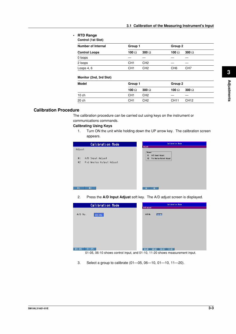
Calibration ProcedureThe calibration procedure can be carried out using keys on the instrument orcommunications commands.
Calibrating Using Keys1. Turn ON the unit while holding down the UP arrow key. The calibration screen
appears.
2. Press the A/D Input Adjust soft key. The A/D adjust screen is displayed.
01-05, 06-10 shows control input, and 01-10, 11-20 shows measurement input.
3. Select a group to calibrate (01—05, 06—10, 01—10, 11—20).
3.1 Calibration of the Measuring Instrument's Input

3-4 SM 04L31A01-01E
4. Press the ENTER key. The A/D adjust screen is displayed.
5. Input the zero and full scale value to the calibration channels shown in"Calibrating the Input Range" (page 3-2).
6. Press the Cal/Exec soft key. The A/D adjust (Cal/Exe) screen is displayed.
CAUTIONIf you select Display in the A/D adjust screen, you can confirm the calibratedvalue and manually input values using keys. Key-based manual calibration has
a large effect on measurement accuracy, so only perform the procedure if youthink it is absolutely necessary.
7. Press the soft key corresponding to the range to be calibrated (20 mV, 60 mV,
200 mV etc.).8. Press the ENTER key. The calibration begins.9. Repeat steps 5—8 and calibrate all ranges.
10. Press ESC. You are returned to the A/D adjust screen.11. Press the End soft key. A dialog box appears asking you whether or not to save
and exit.
12. Select Yes. You are returned to the A/D adjust (Cal/Exe) screen.
13. Repeat steps 3—12 to calibrate and save calibrated values for each group.14. When you are finished with all procedures, turn the power OFF.
3.1 Calibration of the Measuring Instrument's Input
3-5SM 04L31A01-01E
Ad
justm
ents
3
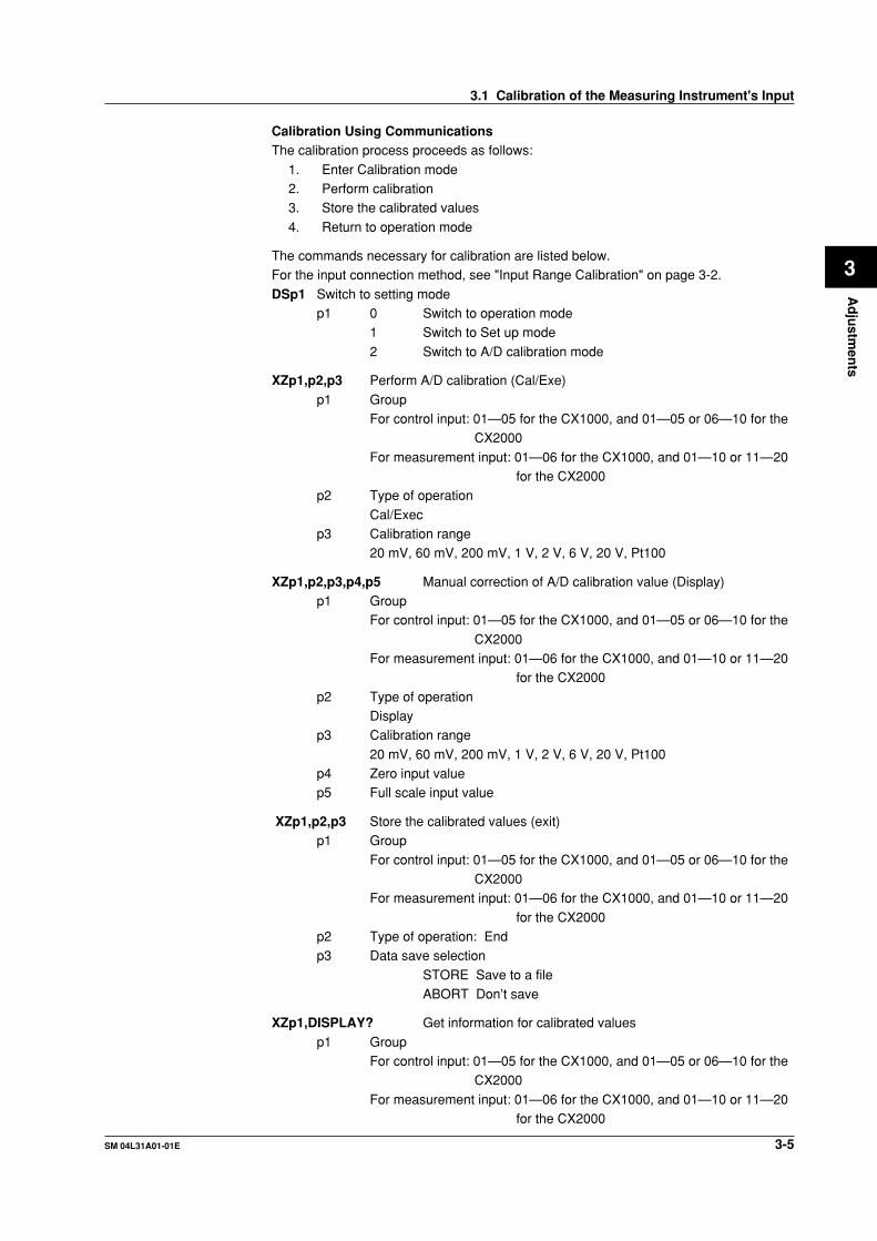
Calibration Using CommunicationsThe calibration process proceeds as follows:
1. Enter Calibration mode2. Perform calibration3. Store the calibrated values
4. Return to operation mode
The commands necessary for calibration are listed below.For the input connection method, see "Input Range Calibration" on page 3-2.
DSp1 Switch to setting modep1 0 Switch to operation mode
1 Switch to Set up mode
2 Switch to A/D calibration mode
XZp1,p2,p3 Perform A/D calibration (Cal/Exe)
p1 GroupFor control input: 01—05 for the CX1000, and 01—05 or 06—10 for the
CX2000
For measurement input: 01—06 for the CX1000, and 01—10 or 11—20for the CX2000
p2 Type of operation
Cal/Execp3 Calibration range
20 mV, 60 mV, 200 mV, 1 V, 2 V, 6 V, 20 V, Pt100
XZp1,p2,p3,p4,p5 Manual correction of A/D calibration value (Display)p1 Group
For control input: 01—05 for the CX1000, and 01—05 or 06—10 for the
CX2000For measurement input: 01—06 for the CX1000, and 01—10 or 11—20
for the CX2000
p2 Type of operationDisplay
p3 Calibration range
20 mV, 60 mV, 200 mV, 1 V, 2 V, 6 V, 20 V, Pt100p4 Zero input valuep5 Full scale input value
XZp1,p2,p3 Store the calibrated values (exit)p1 Group
For control input: 01—05 for the CX1000, and 01—05 or 06—10 for theCX2000
For measurement input: 01—06 for the CX1000, and 01—10 or 11—20
for the CX2000p2 Type of operation: Endp3 Data save selection
STORE Save to a fileABORT Don’t save
XZp1,DISPLAY? Get information for calibrated values
p1 GroupFor control input: 01—05 for the CX1000, and 01—05 or 06—10 for the
CX2000
For measurement input: 01—06 for the CX1000, and 01—10 or 11—20for the CX2000
3.1 Calibration of the Measuring Instrument's Input
3-6 SM 04L31A01-01E
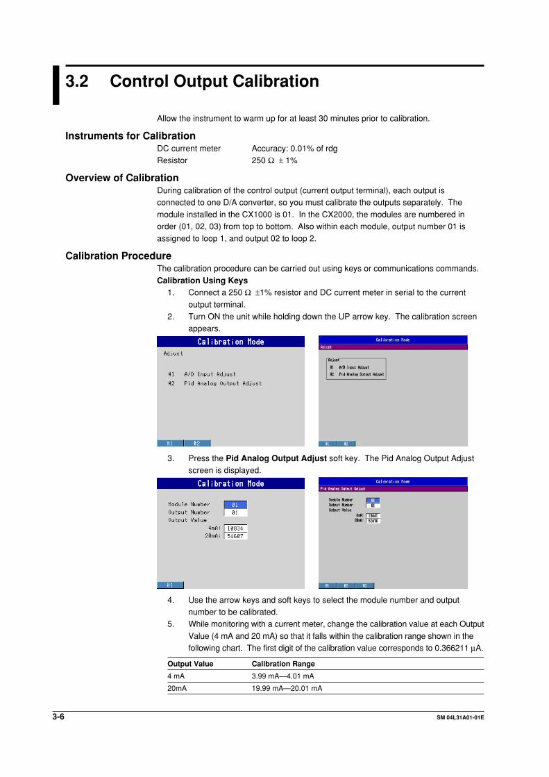
3.2 Control Output Calibration
Allow the instrument to warm up for at least 30 minutes prior to calibration.
Instruments for CalibrationDC current meter Accuracy: 0.01% of rdgResistor 250 Ω ± 1%
Overview of CalibrationDuring calibration of the control output (current output terminal), each output isconnected to one D/A converter, so you must calibrate the outputs separately. The
module installed in the CX1000 is 01. In the CX2000, the modules are numbered inorder (01, 02, 03) from top to bottom. Also within each module, output number 01 isassigned to loop 1, and output 02 to loop 2.
Calibration ProcedureThe calibration procedure can be carried out using keys or communications commands.
Calibration Using Keys1. Connect a 250 Ω ±1% resistor and DC current meter in serial to the current
output terminal.
2. Turn ON the unit while holding down the UP arrow key. The calibration screenappears.
3. Press the Pid Analog Output Adjust soft key. The Pid Analog Output Adjustscreen is displayed.
4. Use the arrow keys and soft keys to select the module number and outputnumber to be calibrated.
5. While monitoring with a current meter, change the calibration value at each Output
Value (4 mA and 20 mA) so that it falls within the calibration range shown in thefollowing chart. The first digit of the calibration value corresponds to 0.366211 µA.
Output Value Calibration Range
4 mA 3.99 mA—4.01 mA
20mA 19.99 mA—20.01 mA

3-7SM 04L31A01-01E
Ad
justm
ents
3
6. Press the Write function key for each output number. The calibration values aresaved.
7. Repeat steps 4—6 and calibrate all module and output numbers.
8. Press ESC. You are returned to the calibration screen.9. Turn OFF the power
Calibration Using CommunicationsThe commands required for control output calibration are listed below.For other necessary commands, see Calibration Using Communications (page 3-5) in
section 3.1, “Calibrating the Measuring Instrument Input.”
Perform step 1 of Calibration Using Keys before using these commands forcalibration.For OUTPUT
ZZp1,p2,p3,p4p1 Action OUTPUTp2 Module number (1 for the CX1000, or 1—3 for the CX2000)p3 Output channels (1 and 2)
p4 4 mA/20 mAp5 Calibration value (For 4 mA, 9285—12561)
(For 20 mA, 46421—62804)
For WRITEZZp1,p2,p3,p4
p1 Action (OUTPUT/WRITE)p2 Module number (1 for the CX1000, or 1—3 for the CX2000)p3 Output channels (1 and 2)
p4 (Calibration value for 4 mA, 9285—12561)p5 (Calibration value for 20 mA, 46421—12561)
NoteWhen specifying WRITE, you can omit p4 and p5. If you do so, the currently set calibration
value is written.
3.2 Control Output Calibration
4-1SM 04L31A01-01E
Rep
lacing
Parts
4
Chapter 4 Replacing Parts
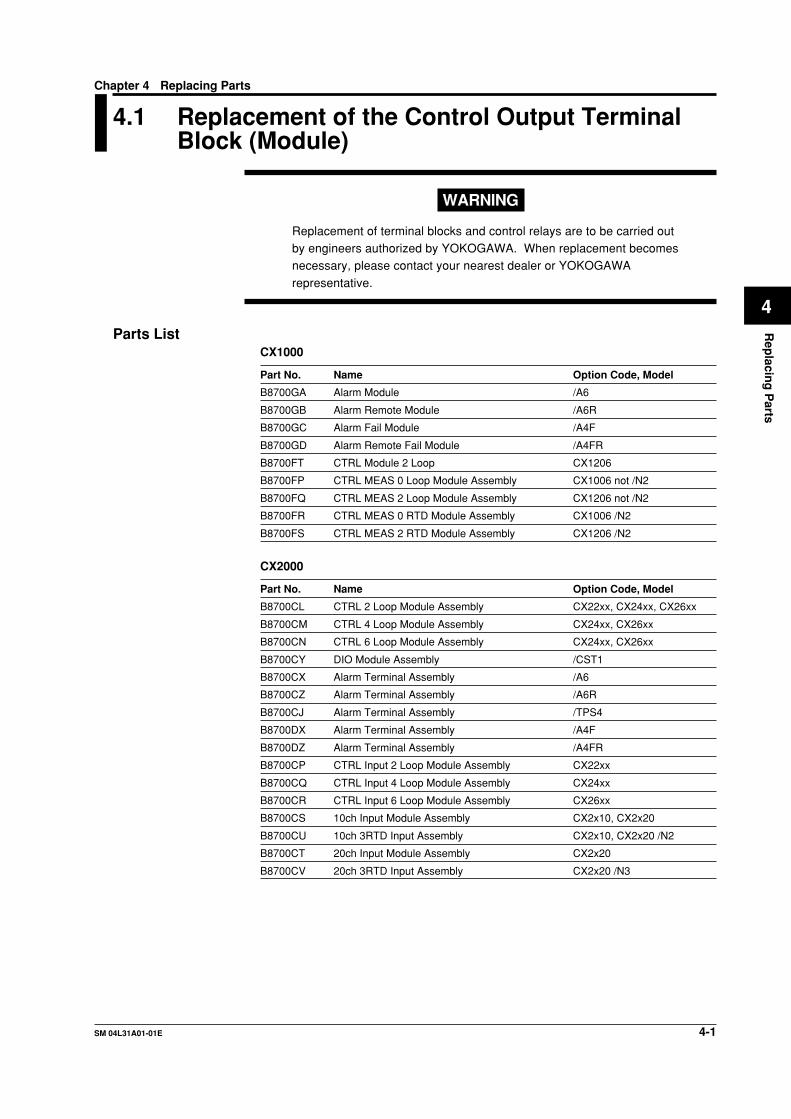
4.1 Replacement of the Control Output TerminalBlock (Module)
WARNING
Replacement of terminal blocks and control relays are to be carried outby engineers authorized by YOKOGAWA. When replacement becomesnecessary, please contact your nearest dealer or YOKOGAWA
representative.
Parts ListCX1000
Part No. Name Option Code, Model
B8700GA Alarm Module /A6
B8700GB Alarm Remote Module /A6R
B8700GC Alarm Fail Module /A4F
B8700GD Alarm Remote Fail Module /A4FR
B8700FT CTRL Module 2 Loop CX1206
B8700FP CTRL MEAS 0 Loop Module Assembly CX1006 not /N2
B8700FQ CTRL MEAS 2 Loop Module Assembly CX1206 not /N2
B8700FR CTRL MEAS 0 RTD Module Assembly CX1006 /N2
B8700FS CTRL MEAS 2 RTD Module Assembly CX1206 /N2
CX2000
Part No. Name Option Code, Model
B8700CL CTRL 2 Loop Module Assembly CX22xx, CX24xx, CX26xx
B8700CM CTRL 4 Loop Module Assembly CX24xx, CX26xx
B8700CN CTRL 6 Loop Module Assembly CX24xx, CX26xx
B8700CY DIO Module Assembly /CST1
B8700CX Alarm Terminal Assembly /A6
B8700CZ Alarm Terminal Assembly /A6R
B8700CJ Alarm Terminal Assembly /TPS4
B8700DX Alarm Terminal Assembly /A4F
B8700DZ Alarm Terminal Assembly /A4FR
B8700CP CTRL Input 2 Loop Module Assembly CX22xx
B8700CQ CTRL Input 4 Loop Module Assembly CX24xx
B8700CR CTRL Input 6 Loop Module Assembly CX26xx
B8700CS 10ch Input Module Assembly CX2x10, CX2x20
B8700CU 10ch 3RTD Input Assembly CX2x10, CX2x20 /N2
B8700CT 20ch Input Module Assembly CX2x20
B8700CV 20ch 3RTD Input Assembly CX2x20 /N3

4-2 SM 04L31A01-01E
Replacement of Each Terminal Block (Module)
WARNING• To prevent electric shock, cut the power to the main unit and disconnect any
wiring that may be connected to it before replacing the terminal block.
• To prevent electric shock when disconnecting wires, ensure the main powersupply is turned OFF.
Follow the procedures below to replace the blocks.1 . Loosen (but do not completely remove) the 2 terminal cover screws,
remove the cover, then remove the wiring from the terminal block.Ignore this step if the terminal block is not wired.
Terminal cover screws
Terminal block attachmentscrews
Connector
Terminal cover screws
Terminal block attachment screws
Connector
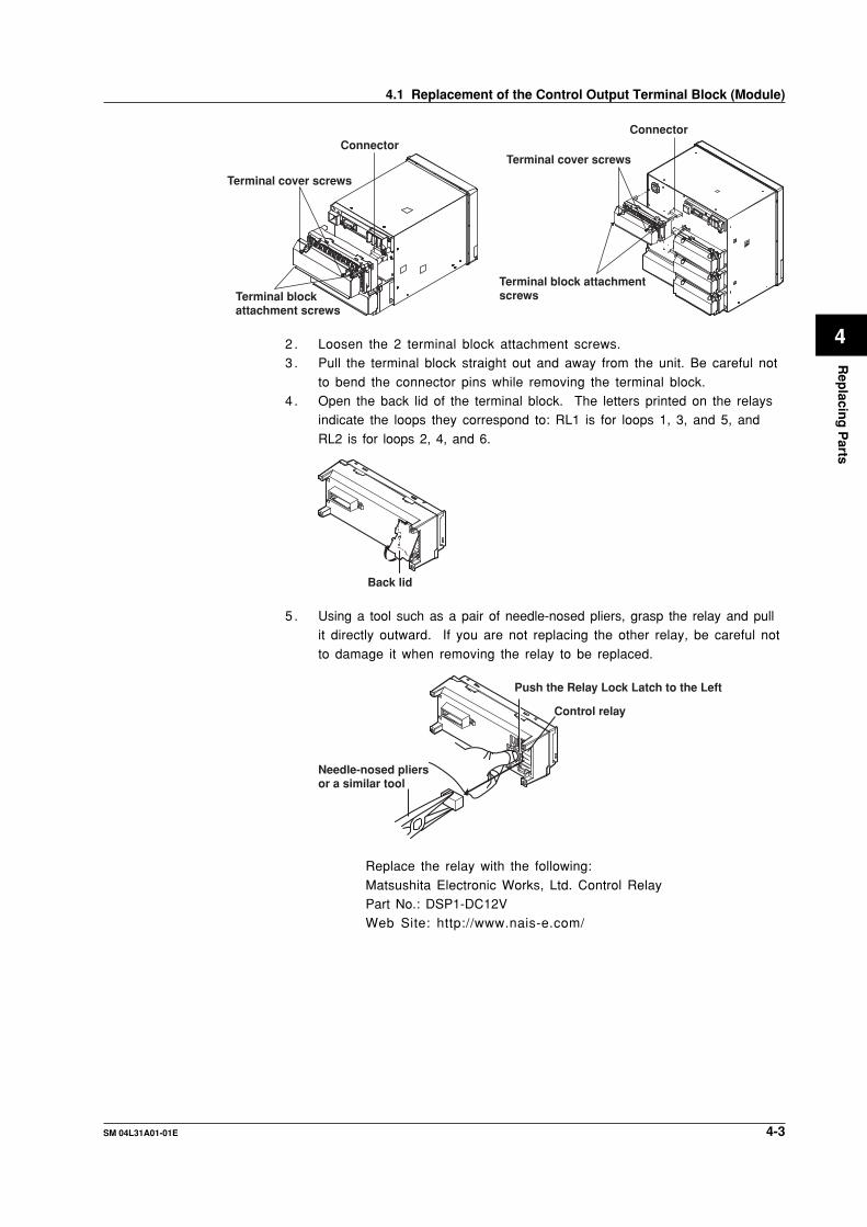
2 . Loosen the 2 terminal block attachment screws.3 . Pull the terminal block straight out and away from the unit. Be careful not
to bend the connector pins while removing the terminal block.4 . Check the angle of the terminal block, install it on the main unit, and then
fasten by tightening the terminal block attachment screws.
5 . Install the terminal cover, and fasten with the terminal cover screws.
When Replacing Only the Control Relay
WARNING• To prevent electric shock, unplug the main power cord before replacing
the control relay.• To prevent electric shock when disconnecting wires, ensure the main
power supply is turned OFF.• To prevent electric shock, use a withstanding voltage tester to check the withstanding
voltage between the relay and the protective grounding after replacing the relay.
Withstand voltage: 1500 VAC, 1 minute• You must perform an insulation resistance test and wishstand voltage test
after replacing the control relay.
Follow the procedures below to replace the blocks.1 . Loosen (but do not completely remove) the 2 terminal cover screws,
remove the cover, then remove the wiring from the terminal block.Ignore this step if the terminal block is not wired.
4.1 Replacement of the Control Output Terminal Block (Module)
4-3SM 04L31A01-01E
Rep
lacing
Parts
4
Terminal cover screws
Terminal block attachmentscrews
Connector
Terminal cover screws
Terminal block attachment screws
Connector
2 . Loosen the 2 terminal block attachment screws.3 . Pull the terminal block straight out and away from the unit. Be careful not
to bend the connector pins while removing the terminal block.4 . Open the back lid of the terminal block. The letters printed on the relays
indicate the loops they correspond to: RL1 is for loops 1, 3, and 5, and
RL2 is for loops 2, 4, and 6.
Back lid
5 . Using a tool such as a pair of needle-nosed pliers, grasp the relay and pullit directly outward. If you are not replacing the other relay, be careful not
to damage it when removing the relay to be replaced.
Control relay
Push the Relay Lock Latch to the Left
Needle-nosed pliers or a similar tool
Replace the relay with the following:
Matsushita Electronic Works, Ltd. Control RelayPart No.: DSP1-DC12VWeb Site: http://www.nais-e.com/
4.1 Replacement of the Control Output Terminal Block (Module)
4-4 SM 04L31A01-01E
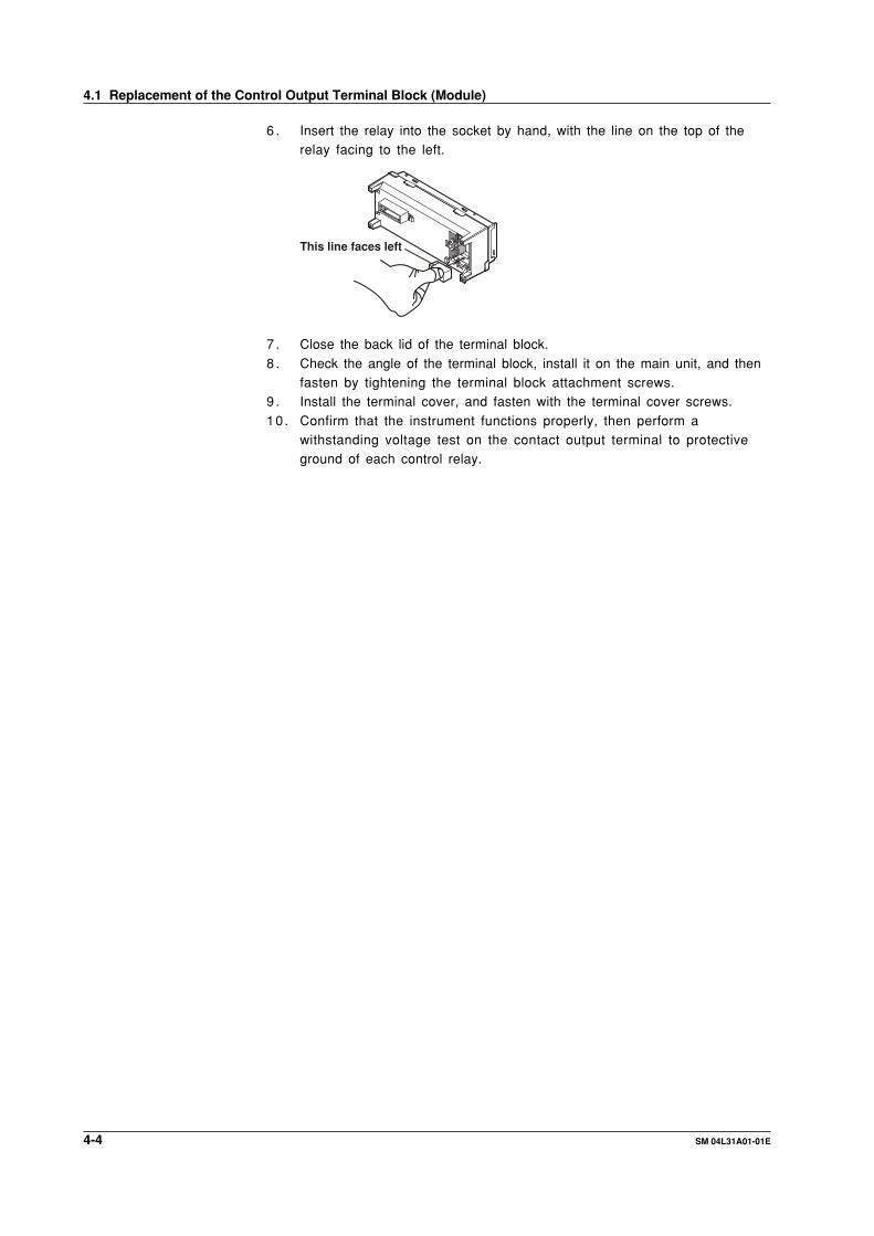
6 . Insert the relay into the socket by hand, with the line on the top of therelay facing to the left.
This line faces left
7 . Close the back lid of the terminal block.
8 . Check the angle of the terminal block, install it on the main unit, and thenfasten by tightening the terminal block attachment screws.
9 . Install the terminal cover, and fasten with the terminal cover screws.
10 . Confirm that the instrument functions properly, then perform awithstanding voltage test on the contact output terminal to protectiveground of each control relay.
4.1 Replacement of the Control Output Terminal Block (Module)
SM 04L05A01-01E 5-1
Tro
ub
lesho
otin
g
5
Chapter 5 Troubleshooting
5.1 Procedure
1 Determine the type of problem.2 Check for possible user error. Check the connections and the settings of
equipment to determine whether there was a handling mistake.3 Execute the self diagnostic test by turning the power ON, and identify any
problem items.
4 Analyze the cause of the problem according to the troubleshooting flow chart.
Do not touch the circuit or parts with live voltage because the power unit contains a high-
voltage electrical circuit. The p ower unit is furnished with a dedicated cover to preventelectric shock. Do not remove this cover. Never touch any part not subject toadjustment.
Make sure to connect input terminals (voltage or current) correctly. The internal circuitmay be damaged when wrongly connected.

SM 04L05A01-01E5-2
5.2 Flow Chart
This flow chart consists of general service operations when a fault occurs. This chart isnot always suitable for every kind of fault. However, it is recommended to perform
operations according to the flow chart.
START
END
YES
YES
NO
NO
Phenomenon check
Cause check
Assembly exchange andadjustment
Performance test execution
Repaired?

SM 04L05A01-01E 5-3
Tro
ub
lesho
otin
g
5
5.3 Troubleshooting Checklist
Trouble Operational
Ch
eck
Ad
just
Exc
han
ge
Check Item
Power cable connection Fuse is blown (/P1 option only)Power ass’y CPU ass’yMemory ass’yDisplay ass’y
CPU ass’yMemory ass’yDisplay ass’yOptional terminal ass’y
Battery connector is disconnected? Battery voltage is low (less than +3.0V)CPU ass’yMemory ass’yDisplay ass’y
FFC ass’y of the keyboard isdisconnected/brokenKeyboard ass’yCPU ass’yMemory ass’yDisplay ass’y
FFC ass’y of the LCD is disconnected/brokenCPU ass’y Memory ass’yDisplay ass’y LCD ass’yInput wiring is disconnectedNoise A/D ass’y Scanner ass’y
Input is disconnectedNoise Terminal cover is removedRJC INT/EXT setting A/D board ass’y Input terminal Scanner board ass’y
Power frequency setting is incorrectNoise
Floppy disk/Zip disk/PC card drive unit
Power is notturned ON
FAIL state
Memory cannotbe backed up
Panel key operationis not normal
LCD is not normal
Measured value
incorrect
Measured
temperature
is incorrect
Measured value fluctuates
External storagemedia is not normal
SM 04L31A01-01A 6-1
Sch
ematic D
iagram
6
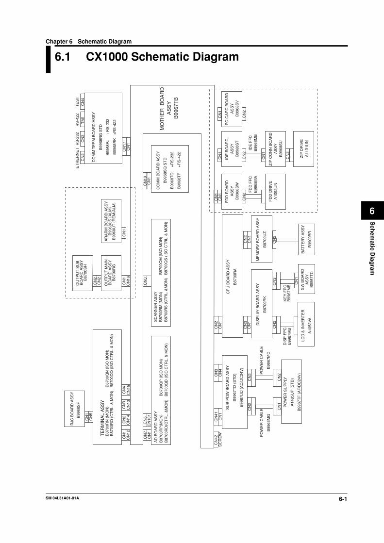
6.1 CX1000 Schematic Diagram
AD
BO
AR
D A
SS
YB
8700
RP
(MO
N)
B
8700
QP
(IS
O M
ON
)B
8700
RD
(CT
RL.
&M
ON
) B
8700
QD
(IS
O C
TR
L. &
MO
N)
CN
7C
N1
CN
8C
N10
1C
N10
CN
1
CO
MM
BO
AR
D A
SS
Y
B99
68S
Q S
TD
B99
68T
Q
+R
S-2
32
B99
68T
P
+R
S-4
22
CN
17C
N1
CN
4T
ES
T
CO
MM
TE
RM
BO
AR
D A
SS
Y
B99
68R
G S
TD
B99
68R
J
+R
S-2
32
B99
68R
K
+R
S-4
22
MO
TH
ER
BO
AR
D
AS
SY
B99
67T
B
CN
2C
N3
TM
1
CN
42C
N41
CN
1C
N4
CN
3S
CR
EW
SU
B P
OW
BO
AR
D A
SS
Y
B99
67T
D (
ST
D)
B99
67U
D (
AC
/DC
24V
)
CN
2
CN
1C
N2
CN
3
CN
2C
N1
CN
3C
N1
CN
2C
N3
CN
1
CN
2
CN
2C
N1
PO
WE
R C
AB
LE
B99
68M
G
PO
WE
R C
AB
LE
B99
67M
C
PO
WE
R S
UP
PLY
A14
85U
P (
ST
D)
B99
67T
F (
AF
/DC
24V
)
CP
U B
OA
RD
AS
SY
B87
00R
A
DIS
PLA
Y B
OA
RD
AS
SY
B87
00R
K
ME
MO
RY
BO
AR
D A
SS
Y
B87
00U
Z
KE
Y F
PC
B99
67M
B
BAT
TE
RY
AS
SY
B99
00B
R
SW
BO
AR
DA
SS
YB
9967
TC
LCD
& IN
VE
RT
ER
A10
53V
A
CN
1
CN
2
PC
-CA
RD
BO
AR
D
AS
SY
B99
68S
V
IDE
BO
AR
D
AS
SY
B99
68S
T
FD
D B
OA
RD
A
SS
YB
9968
SW
IDE
FF
CB
9968
MB
FD
D F
FC
B99
68M
A
RS
-232
ET
HE
RN
ET
RS
-422
CN
1
CN
2
CN
1
CN
2
CN
1
RJC
BO
AR
D A
SS
Y
B99
68S
F
CN
1C
N5
TE
RM
INA
L A
SS
YB
8700
RN
(M
ON
)
B87
00Q
N (
ISO
MO
N)
B87
00R
Q (
CT
RL.
& M
ON
) B
8700
(IS
O C
TR
L. &
MO
N)
CN
1C
N12
CN
2C
N14
CN
3C
N13
CN
4C
N15
OU
TP
UT
SU
B
BO
AR
D A
SS
YB
8700
SH
CN
2C
N2
CN
1C
N16
OU
TP
UT
MA
INB
OA
RD
AS
SY
B87
00R
G
CN
1
AR
AR
M B
OA
RD
AS
SY
B99
68U
S (
ALM
)B
9968
UT
(R
EM
/ALM
)
ZIP
CO
NN
BO
AR
D
AS
SY
B99
68S
U
CN
1
CN
2
FD
D D
RIV
EA
1092
UN
ZIP
DR
IVE
A11
31U
N
SC
AN
NE
R A
SS
YB
8700
RM
(M
ON
)
B87
00Q
M (
ISO
MO
N)
B87
00R
S (
CT
RL.
&M
ON
) B
8700
QS
(IS
O C
TR
L. &
MO
N)
CN
3
DIS
P F
PC
B99
67M
B
Chapter 6 Schematic Diagram
SM 04L31A01-01A6-2
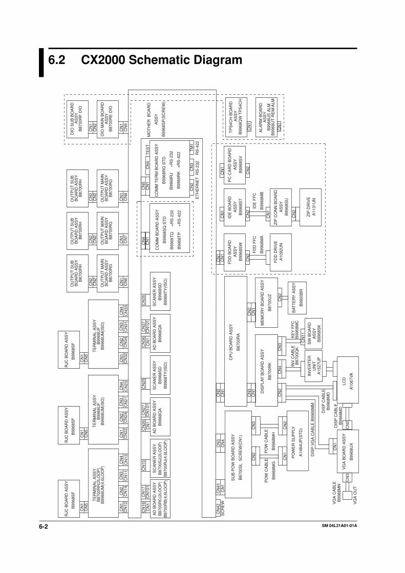
6.2 CX2000 Schematic Diagram
AD
BO
AR
D A
SS
YB
8700
RC
(2LO
OP
)B
8700
RB
(4,6
LOO
P)
CN
16C
N1
CN
17C
N10
1C
N4
CN
1
CO
MM
BO
AR
D A
SS
Y
B99
68S
Q S
TD
B99
68T
Q
+R
S-2
32
B99
68T
P
+R
S-4
22
CN
5C
N1
CN
4T
ES
T
CO
MM
TE
RM
BO
AR
D A
SS
Y
B99
68R
G S
TD
B99
68R
J
+R
S-2
32
B99
68R
K
+R
S-4
22
MO
TH
ER
BO
AR
D
AS
SY
B99
68S
P(S
CR
EW
)
CN
2C
N3
TM
1
CN
42C
N41
CN
1C
N4
CN
3S
CR
EW
SU
B P
OW
BO
AR
D A
SS
Y
B87
00S
L S
CR
EW
(CN
1)
CN
2
CN
1
CN
1
CN
2
CN
3
CN
2C
N1
CN
3C
N1
CN
2C
N3
CN
11
CN
2
CN
2C
N1
PO
W C
AB
LE
B99
68M
G
PO
W C
AB
LE
B99
68M
H
PO
WE
R S
UP
PLY
A14
84U
P(S
TD
)
CP
U B
OA
RD
AS
SY
B87
00R
A
DIS
PLA
Y B
OA
RD
AS
SY
B87
00R
K
ME
MO
RY
BO
AR
D A
SS
Y
B87
00U
Z
INV
CA
BLE
B87
00Q
KK
EY
FF
CB
9968
MC
BAT
TE
RY
AS
SY
B99
00B
R
SW
BO
AR
DA
SS
YB
9968
SK
LCD
A10
67V
A
CN
1
CN
2
PC
-CA
RD
BO
AR
D
AS
SY
B99
68S
V
IDE
BO
AR
D
AS
SY
B99
68S
T
FD
D B
OA
RD
A
SS
YB
9968
SW
IDE
FF
C
B99
68M
B
FD
D F
FC
B99
68M
A
RS
-232
ET
HE
RN
ET
RS
-422
CN
1
CN
2
CN
1
CN
2
CN
1
INV
ER
TE
RU
NIT
A15
27U
P
VG
A B
OA
RD
AS
SY
B99
68U
X
CN
4
RJC
BO
AR
D A
SS
Y
B99
68S
F
CN
1C
N5
TE
RM
INA
L A
SS
YB
8700
RR
(2LO
OP
)B
9968
UM
(4,6
LOO
P)
CN
1C
N12
CN
2C
N14
CN
3C
N11
CN
4C
N13
RJC
BO
AR
D A
SS
Y
B99
68S
F
CN
1C
N5
TE
RM
INA
L A
SS
YB
9968
UF
B99
68U
M(I
SO
)
CN
1C
N22
CN
2C
N24
CN
3C
N21
CN
4C
N23
RJC
BO
AR
D A
SS
Y
B99
68S
F
CN
1C
N5
TE
RM
INA
L A
SS
YB
9968
UF
B99
68U
M(I
SO
)
CN
1C
N32
CN
2C
N34
CN
3C
N31
CN
4C
N33
OU
TP
UT
SU
B
BO
AR
D A
SS
YB
8700
RH
CN
2C
N2
CN
1C
N6
OU
TP
UT
MA
INB
OA
RD
AS
SY
B87
00R
G
OU
TP
UT
SU
B
BO
AR
D A
SS
YB
8700
RH
CN
2C
N2
CN
1C
N7
OU
TP
UT
MA
INB
OA
RD
AS
SY
B87
00R
G
OU
TP
UT
SU
B
BO
AR
D A
SS
YB
8700
RH
CN
2C
N2
CN
1C
N8
OU
TP
UT
MA
INB
OA
RD
AS
SY
B87
00R
G
DIO
SU
B B
OA
RD
AS
SY
B87
00R
F D
IO
CN
1C
N2
CN
1C
N9
DIO
MA
IN B
OA
RD
A
SS
YB
8700
RE
DIO
TP
S4C
H B
OA
RD
A
SS
YB
9968
QW
TP
S4C
H
CN
1
CN
1
ALA
RM
BO
AR
D
AS
SY
B99
68U
S A
LMB
9968
UT
RE
M/A
LMZ
IP C
ON
N B
OA
RD
A
SS
YB
9968
SU
CN
1
CN
2
FD
D D
RIV
EA
1092
UN
ZIP
DR
IVE
A11
31U
N
SC
AN
ER
AS
SY
B87
00S
J(2L
OO
P)
B87
00R
J(4,
6LO
OP
)
CN
15
AD
BO
AR
D A
SS
YB
9968
QA
CN
26C
N1
CN
27C
N10
1
SC
AN
ER
AS
SY
B99
68S
DB
9968
TY
(IS
O)
CN
25
AD
BO
AR
D A
SS
YB
9968
QA
CN
36C
N1
CN
37C
N10
1
SC
AN
ER
AS
SY
B99
68S
DB
9968
TY
(IS
O)
CN
35
CN
2C
N3
VG
A O
UT
VG
A C
AB
LEB
9968
MN
DIS
P-V
GA
CA
BLE
B99
68M
M
DIS
P C
AB
LEB
9968
MD
DIS
P C
AB
LEB
9968
MD
7-1SM 04L31A01-01A
Cu
stom
er Main
tenan
ce Parts L
ist
7
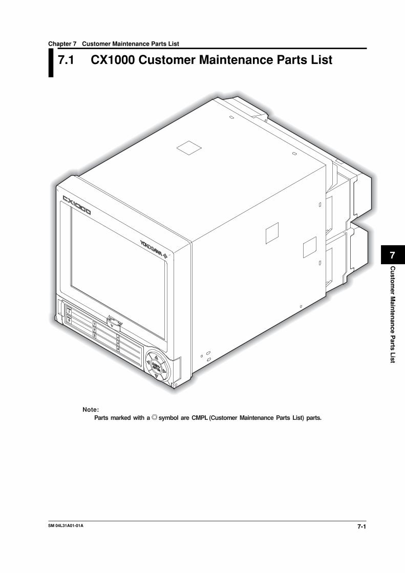
7.1 CX1000 Customer Maintenance Parts List
Note:Parts marked with a symbol are CMPL (Customer Maintenance Parts List) parts.
Chapter 7 Customer Maintenance Parts List
7-2 SM 04L31A01-01A
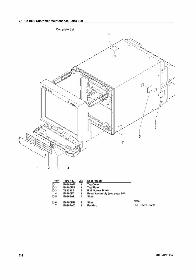
Complete Set
1 2 3 4
5
6
7
5
Packing1B9967AX7
1DescriptionTag Cover1
ItemB9967AMPart No. Qty
345
6
B8700ENY9308LBB8700FAB9968AT
B8700DR
1214
2
Tag PlateB.H. Screw, M3x8Bezel Assembly (see page 7-5)Sheet
Sheet
2
Note:
CMPL Parts
7.1 CX1000 Customer Maintenance Parts List
7-3SM 04L31A01-01A
Cu
stom
er Main
tenan
ce Parts L
ist
7
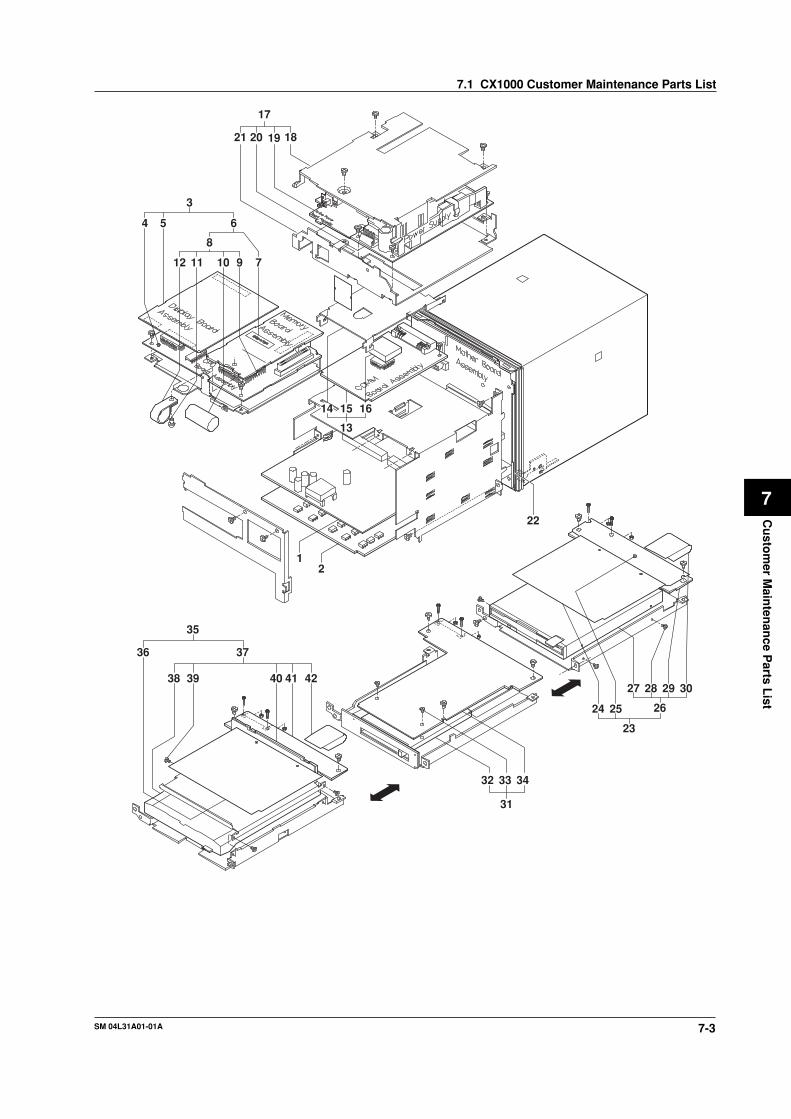
12 11 10 9 7
8
4 5 6
3
21 20 19 18
17
13
14 15 16
12
22
23
24 25 26
27 28 29 30
31
32 33 34
36
38 39
35
37
40 41 42
7.1 CX1000 Customer Maintenance Parts List
7-4 SM 04L31A01-01A
(select)
(select)
(select)
(select)
Mother Board Assembly1B9967TB22
Note:CMPL Parts
(select)
42 B9968MB 1 IDE FFC41 B9968ST 1 IDE Board Assembly
36
3332
FDD FCC1B9968MA30FDD Board Assembly1B9968SW29Screw3Y9204LS28Memory System1A1092UN27
FDD Drive Assembly1B9968GA26
Sheet1B9967DN25
S-Power Assembly (not /P1)
Power Bracket Cover (not /P1)
2423
21
20
19
18
17
16
14COMM Board Assembly (CX1 6- -0)
COMM Board Assembly (CX1 6- -2)COMM Board Assembly (CX1 6- -1)
ClampRivetBattery Assembly
Name PlateMemory AssemblyDisplay Board Assembly
CPU Board AssemblyCPU Board AssemblyISO C&M Scanner Assembly (CX1206 /N2)ISO MON Scanner Assembly (CX1006 /N2)C&M Scanner Assembly (CX1206 not /N2)
15
13121110
765
43
MON Scanner Assembly (CX1006 not /N2)
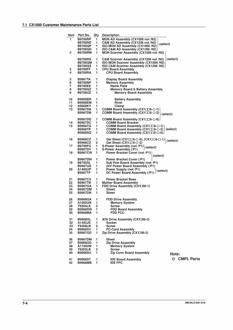
1DescriptionItem Part No. Qty
2
B8700RPB8700RDB8700QP
B8700RM
B8700RSB8700QMB8700QSB8700FFB8700RA
B9967TAB8700NPB8700EE
B9900BRB9968EMA9069KYB9967DAB9967DB
B9967DDB9967DCB9968TQB9968TPB9968SQ
B9968CZB9968CZB8700FG
B9967CW
B8700SL
A1485UP
B9967CX
B9967GAB9967DM
111
1
11111
111
11111
11111
121
1
1
1
1
11
COMM Board BracketCOMM Board Assembly (CX1 6- -1)COMM Board Assembly (CX1 6- -2)COMM Board Assembly (CX1 6- -0)
Gel Sheet (CX1 6- -0), (CX1 6- -1)Gel Sheet (CX1 6- -2)
Sub Pow Board Assembly (not /P1)
Power Supply (not /P1)
Power Bracket Base
FDD Drive Assembly (CX1 06-1)Sheet
1 ATA Drive Assembly (CX1 06-3)31 B9968GL
3435
37383940
A1492JSY9208LBB9968SVB9967GD
B9967DMB9968GDA1150UNY9203LBB9968SU
1211
11131
SocketScrewPC-Card Assembly
Zip Drive Assembly (CX1 06-2)
SheetZip Drive Assembly
Memory SystemScrewZip Conn Board Assembly
MON AD Assembly (CX1006 not /N2)C&M AD Assembly (CX1206 not /N2)ISO MON AD Assembly (CX1006 /N2)
8 B8700QZ 1 Memory Board & Battery Assembly9 B8700UZ 1 Memory Board Assembly
B9967DV 1 S-Power Assembly (/P1)
B9967DW 1 Power Bracket Cover (/P1)(select)
B9967UD 1 24V Power Board Assembly (/P1)
B9967TF 1 DC Power Board Assembly (/P1)(select)
B8700QD 1 ISO C&M AD Assembly (CX1206 /N2)
(select)
7.1 CX1000 Customer Maintenance Parts List

7-5SM 04L31A01-01A
Cu
stom
er Main
tenan
ce Parts L
ist
7
Bezel Assembly
20
1921
22
17
16
18a
18c
18b
18
12
13
14
15
11
10
9
8
7
1
432 65
QtyPart No.Item
2019
Display FFC1B9967MBHinge Arm2B9968BM
21 B9967BY 1 Stay Bracket22 B9968EN 1 Bushing
1213141516
1718
B9967BUB9967AYB9967MAB9967BTB9967BX
B8700FBB9967BF
21111
11
ScrewPackingKey FPCFPC Guard
Rivet
Sub Bezel AssemblyLCD Assembly
LCD1A1053VA18a18b B9967AQ 1 Name Plate18c A1039VZ 1 Back Light Module
DescriptionQtyPart No.Item Description
11
B9967BZ10 Micro SW Pin1
B9967BK 1 Front Case
9 SW Board Assembly1B9967TC
B8700FH1 Key Case Assembly12345
678
B9967BNB9567AQB9967BPE9655AL
B9967BMB9967BJB8700FL
1111
111
Hinge PinSpringFront PlateSpring
Door KnobFront CoverKey Top
7.1 CX1000 Customer Maintenance Parts List

7-6 SM 04L31A01-01A
2524
27
26
2322
28
2120
1918
5
42
3
6
8
7
1
14
1312
11
15
17
16
10
9
7.1 CX1000 Customer Maintenance Parts List
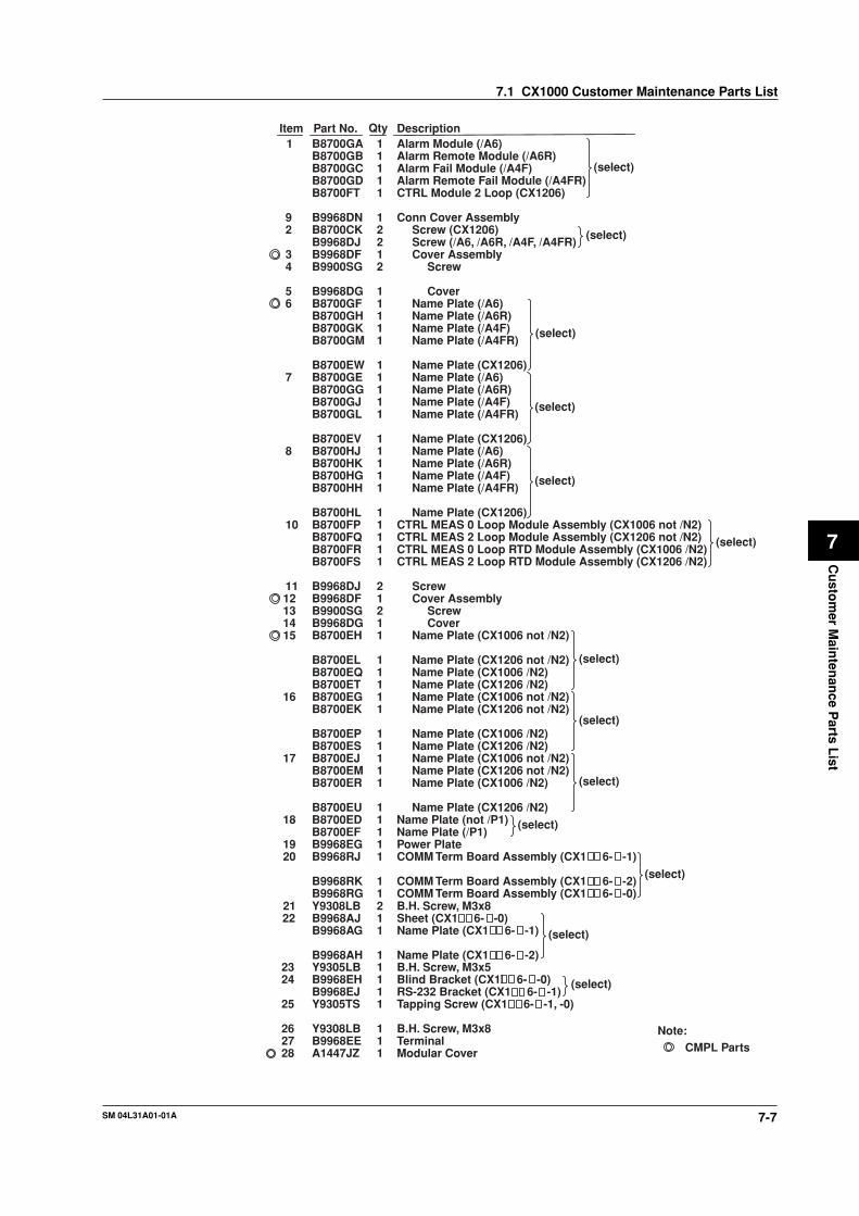
7-7SM 04L31A01-01A
Cu
stom
er Main
tenan
ce Parts L
ist
7
(select)
(select)
(select)
(select)
(select)
(select)
(select)
(select)
1
111
B8700EU
B8700ERB8700EMB8700EJ17
16 B8700EGB8700EK
B8700EPB8700ES
11
11
B8700FP 1 CTRL MEAS 0 Loop Module Assembly (CX1006 not /N2)CTRL MEAS 2 Loop Module Assembly (CX1206 not /N2)1B8700FQ
B8700FR 1 CTRL MEAS 0 Loop RTD Module Assembly (CX1006 /N2)B8700FS 1 CTRL MEAS 2 Loop RTD Module Assembly (CX1206 /N2)
10
8B8700EV 1
(select)Name Plate (/P1)1B8700EF
1B8700HL
1B8700HH1B8700HG
B8700HK 11B8700HJ
(select)
Name Plate (CX1206)
Name Plate (/A4FR)Name Plate (/A4F)Name Plate (/A6R)
Conn Cover Assembly
CTRL Module 2 Loop (CX1206)Alarm Remote Fail Module (/A4FR)Alarm Fail Module (/A4F)
TerminalB.H. Screw, M3x8
Tapping Screw (CX1 6- -1, -0)RS-232 Bracket (CX1 6- -1)Blind Bracket (CX1 6- -0)B.H. Screw, M3x5Name Plate (CX1 6- -2)
Name Plate (CX1 6- -1)
11
11111
1
B9968EEY9308LB
Y9305TSB9968EJB9968EHY9305LBB9968AH
B9968AG
2726
25
2423
B9968AJ22 Sheet (CX1 6- -0)1B.H. Screw, M3x8COMM Term Board Assembly (CX1 6- -0)COMM Term Board Assembly (CX1 6- -2)
COMM Term Board Assembly (CX1 6- -1)Power Plate
Name Plate (not /P1)
Name Plate (CX1206 /N2)Name Plate (CX1006 /N2)Name Plate (CX1206 not /N2)
Name Plate (CX1006 not /N2)CoverScrew
Cover AssemblyScrew
Name Plate (/A6)Cover
ScrewCover Assembly
Screw (CX1206)
Alarm Remote Module (/A6R)
211
11
1
111
11212
11111
11111
21
21
1111
Y9308LBB9968RGB9968RK
B9968RJB9968EG
B8700ED
B8700ETB8700EQB8700EL
B8700EHB9968DGB9900SGB9968DFB9968DJ
B8700GLB8700GJB8700GGB8700GEB8700EW
B8700GMB8700GKB8700GHB8700GFB9968DG
B9900SGB9968DF
B8700CKScrew (/A6, /A6R, /A4F, /A4FR)2B9968DJ
B9968DN
B8700FTB8700GDB8700GCB8700GB
21
2019
18
1514131211
7
65
43
2
QtyPart No.B8700GA
Item1 Alarm Module (/A6)
Description1
9
28 A1447JZ 1 Modular Cover
Note:CMPL Parts
Name Plate (/A6)Name Plate (/A6R)Name Plate (/A4F)Name Plate (/A4FR)
Name Plate (CX1206)
Name Plate (CX1206)
Name Plate (/A4FR)Name Plate (/A4F)Name Plate (/A6R)Name Plate (/A6)
Name Plate (CX1006 not /N2)Name Plate (CX1206 not /N2)
Name Plate (CX1006 /N2)Name Plate (CX1206 /N2)
Name Plate (CX1206 /N2)
Name Plate (CX1006 /N2)Name Plate (CX1206 not /N2)Name Plate (CX1006 not /N2)
(select)
(select)
(select)
7.1 CX1000 Customer Maintenance Parts List
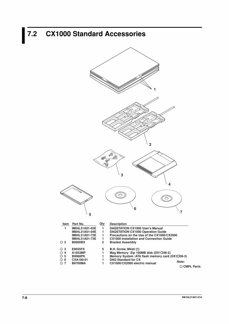
7-8 SM 04L31A01-01A
7.2 CX1000 Standard Accessories
6
Part No.Item1
2
Description
345
7
DAQSTATION CX1000 User’s ManualDAQSTATION CX1000 Operation GuidePrecautions on the Use of the CX1000/CX2000CX1000 Installation and Connection GuideBracket Assembly
11112
IM04L31A01-03EIM04L31A01-04EIM04L31A01-72EIM04L31A01-73EB9900BX
E9655FX 5 B.H. Screw, M4x6 ( )A1053MP 1 Mag Memory :Zip 100MB disk (DX1 06-2)B9968PK 1CXA100-01 1 DAQ Standard for CX
Memory System :ATA flash memory card (DX1 06-3)
Qty
CMPL Parts
Note:B8700MA 1 CX1000/CX2000 electric manual
1
2
3
4
5
67
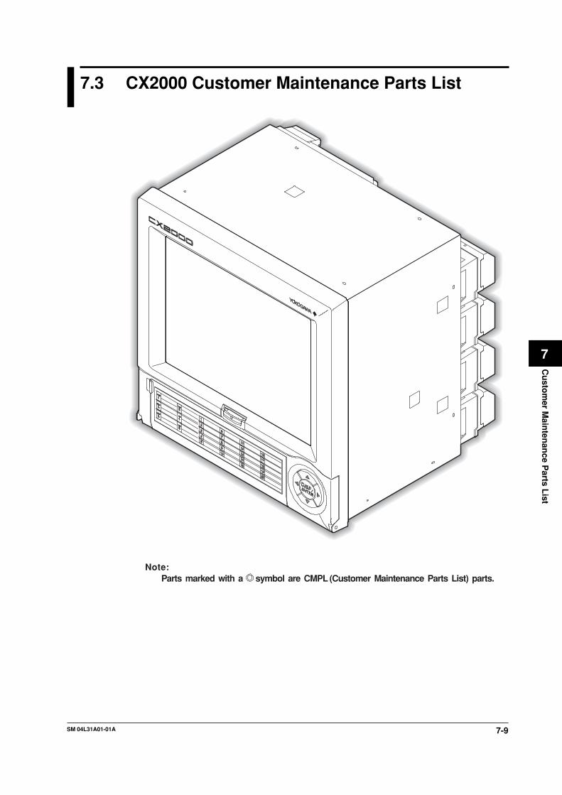
7-9SM 04L31A01-01A
Cu
stom
er Main
tenan
ce Parts L
ist
7
7.3 CX2000 Customer Maintenance Parts List
Note:Parts marked with a symbol are CMPL (Customer Maintenance Parts List) parts.

7-10 SM 04L31A01-01A
Complete Set
7
56
1
234
Sheet
1DescriptionBezel Assembly1
ItemB8700BAPart No. Qty
234
567
B8700BEY9414LBB8700AFB9968AM
B9968ATB8700DRB9968AX
1311
441
Bezel Assembly*B.H. Screw, M4x14Tag PlateTag Cover
Sheet
Packing
(select) (see page 7-13)
CX2 0- - -1Note:
*† CX2 0- - -2
CMPL parts
†
7.3 CX2000 Customer Maintenance Parts List
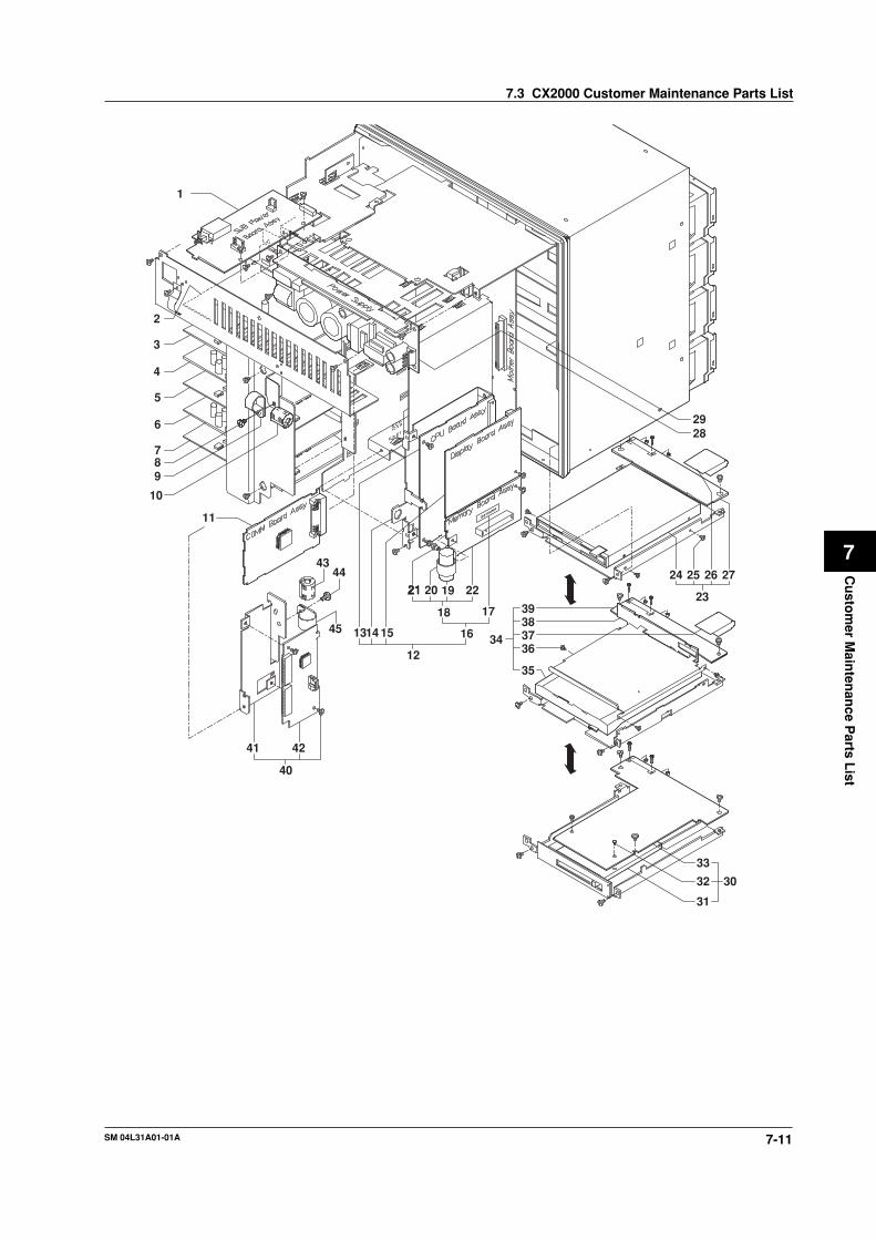
7-11SM 04L31A01-01A
Cu
stom
er Main
tenan
ce Parts L
ist
7
10
98
16
17
35
31
32
33
30
34
39383736
26
1
2
7
6
5
4
3
11
1413
12
15
2928
272524
232221 20 19
18
40
41 42
4344
45
7.3 CX2000 Customer Maintenance Parts List
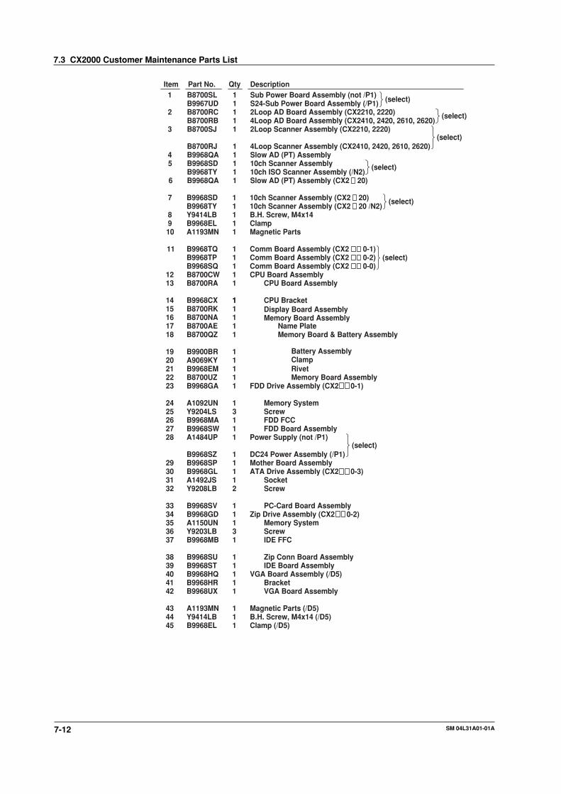
7-12 SM 04L31A01-01A
(select)10ch Scanner Assembly (CX2 20 /N2)1B9968TY
10ch ISO Scanner Assembly (/N2)
FDD Drive Assembly (CX2 0-1)
Comm Board Assembly (CX2 0-2)
(select)
(select)
(select)
Mother Board Assembly1B9968SP29
CPU Board Assembly
Display Board Assembly1B8700RK1
Magnetic Parts1A1193MN10Clamp1B9968EL9B.H. Screw, M4x141Y9414LB8
IDE Board AssemblyZip Conn Board Assembly
IDE FFCScrewMemory System
Zip Drive Assembly (CX2 0-2)
11
1311
B9968STB9968SU
B9968MBY9203LBA1150UNB9968GD
3938
37363534
(select)
QtyPart No.Item Description
(select)1
2
3
45
6
7
11
1213
141516
1920212223
2425262728
B8700SL
B8700RCB8700RBB8700SJ
B8700RJB9968QAB9968SDB9968TYB9968QA
B9968SD
B9968TQB9968TPB9968SQB8700CWB8700RA
B9968CX
B8700NA
B9900BRA9069KYB9968EMB8700UZB9968GA
A1092UNY9204LSB9968MAB9968SWA1484UP
1
111
11111
1
11111
1
1
11111
13111
Sub Power Board Assembly (not /P1)
2Loop AD Board Assembly (CX2210, 2220)4Loop AD Board Assembly (CX2410, 2420, 2610, 2620)2Loop Scanner Assembly (CX2210, 2220)
4Loop Scanner Assembly (CX2410, 2420, 2610, 2620)Slow AD (PT) Assembly10ch Scanner Assembly
Slow AD (PT) Assembly (CX2 20)
10ch Scanner Assembly (CX2 20)
Comm Board Assembly (CX2 0-1)
Comm Board Assembly (CX2 0-0)
CPU Board Assembly
CPU Bracket
Memory Board Assembly
Battery AssemblyClampRivetMemory Board Assembly
Memory SystemScrewFDD FCCFDD Board Assembly
Power Supply (not /P1)
303132
33
B9968GLA1492JSY9208LB
B9968SV
112
1
ATA Drive Assembly (CX2 0-3)SocketScrew
PC-Card Board Assembly
17 B8700AE 1 Name Plate18 B8700QZ 1 Memory Board & Battery Assembly
B9967UD 1 S24-Sub Power Board Assembly (/P1)
B9968SZ 1 DC24 Power Assembly (/P1)(select)
Clamp (/D5)1B9968EL45B.H. Screw, M4x14 (/D5)1Y9414LB44Magnetic Parts (/D5)1A1193MN43
VGA Board Assembly1B9968UX42Bracket1B9968HR41
40 B9968HQ 1 VGA Board Assembly (/D5)
7.3 CX2000 Customer Maintenance Parts List

7-13SM 04L31A01-01A
Cu
stom
er Main
tenan
ce Parts L
ist
7
Bezel Assembly
27
26
24 23
2922
20
21
19
18
1617
5
15
14
13
76
432
1
8
9
10
11
12
25
28
(select)Key Case Assembly (for Japanese)B8700BV
NRP-345Hinge BracketHinge Arm
ScrewBushingPower SupplyStay Bracket
Back LightLCD
512
2111
11
B9543SQB9968BQB9968BM
B9988DLB9968ENA1527UPB9968BL
A1046VZA1067VA
252423
22212019
2917
Front CaseSwitch Board Assembly
Key Top (for English)Hinge PinSpringFront Cover
Front PlateSpringDoor Knob
11
1111
111
B9968BTB9968SK
B8700BWB9968BYB9567AQB9968BS
B9968BWB9900NQB9968BX
109
8765
432
1
Description
Sub Bezel Assembly16
Item
B8700BB
Part No.
1DescriptionKey Case Assembly (for English)1
ItemB8700BRPart No.
11 B9968BZ 1 Micro Switch Pin12 B9968AY 1 Packing
Hinge Bracket1B9968BP26Blind Sheet1B8700DD27
13 B9968GZ 5 Screw
14 B9968BU 1 FPC Guard15 B9968MC 1 Key FFC
B8700BY Key Top (for Japanese) (select)
28 B8700DC 1 Blind Sheet
Mo
del
B87
00B
EB
8700
BA
Qty
1
Mo
del
B87
00B
EB
8700
BA
Qty
1
11
111
111
115
1
512
2111
1
Inverter Cover1B9968ML18 1
11
11
1
1
7.3 CX2000 Customer Maintenance Parts List
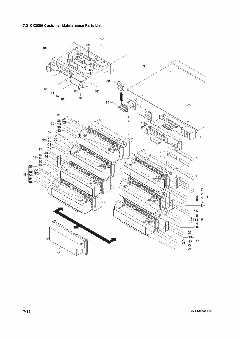
7-14 SM 04L31A01-01A
5859
6564
57
69
70
71
666362
6168
60
312726 2829
3032
25
3536
39
34373840
33
4344
47
42454648
41
5152
55
50535456
49
1
72368
45
9
1510111416
1312
17
2318192224
2120
67
7.3 CX2000 Customer Maintenance Parts List

7-15SM 04L31A01-01A
Cu
stom
er Main
tenan
ce Parts L
ist
7
Name Plate (/A4FR)1B8700HH
Name Plate (/A4FR)1B8700DF
Name Plate (/A4FR)1B8700DH
(select)Screw (/A6 /A6R /TPS4 /A4F /A4FR)2B9968DJ
(select)
(select)
Name Plate (/A4F)1B8700HGName Plate (/TPS4)1B8700HXName Plate (/A6R)1B8700HKName Plate (/A6)1B8700HJ
Name Plate (/CST1)1B8700HY56
(select)
Name Plate (/A4F)1B8700DEName Plate (/TPS4)1B8700HZ
Name Plate (/A4F)1B8700DGName Plate (/TPS4)1B8700HW
Name Plate1B8700HN48
Name Plate1B8700HM40
Name PlateB8700HL32
(select)Name Plate (for B8700CV)1B8700HVName Plate (for B8700CT)1B8700HT24
(select)Name Plate (for B8700CU)1B8700HUName Plate (for B8700CS)1B8700HS16
(select)
Name Plate (for B8700CR)1B8700HRName Plate (for B8700CQ)1B8700HQ
Name Plate (for B8700CP)1B8700HP8
(select)
(select)
(select)
22
14
‡ CX2 0- -2
CX2 0- -1†
*
Note:
CX2 0- -0
(select)
(select)
(select)
(select)
(select)
(select)
(select)
(select)
(select)
(select)Name Plate (/P1)1B9968HM
Modular Cover1A1447JZ
71
(select)
(sel
ect)
(select)
(select)
1
QtyPart No.Item Description
Cover Assembly
Screw
CTRL IN MO. AS. 2L (CX22 )
QtyPart No.
B8700CP
Item
1
Description
1B8700CQ 1 CTRL IN MO. AS. 4L (CX24 )
2
345
B9968DJ
B9968DFB9900SGB9968DG
2
121
ScrewCover
Name Plate (for B8700CP)Name Plate (for B8700CQ)
11
B8700APB8700AQ
6
Cover Assembly
Screw
INPUT MO. AS. 10ch (CX2 10, 2 20)B8700CS9 1B8700CU 1 3RTD INP. AS. 10ch (CX2 10, 2 20 /N2)
10
1112
B9968DJ
B9968DFB9900SGB9968DG
2
121
ScrewCover
Name Plate (for B8700CS)Name Plate (for B8700CU)
11
B8700AJB8700BF
13
Cover AssemblyScrew
INPUT MO. AS. 20ch (CX2 20)B8700CT17 1B8700CV 1 3RTD INP. AS. 20ch (CX2 20 /N3)
1819
2021
B9968DJB9968DF
B9900SGB9968DG
21
21
ScrewCover
Name Plate (for B8700CT)
Name Plate (for B8700CV)
1
1
B8700AK
B8700BG
23
(select)
25 B8700CL 1 CTRL Module AS. 2L (CX22 , CX24 , CX26 )B9968DN 1 Conn Cover Assembly (CX20 )
26 B9968DF 1 Cover Assembly27 B9968DG 1 Cover28 B9900SG 2 Screw29 B8700CK 2 Screw30 B8700AL 1 Name Plate
33 B8700CM 1 CTRL Module AS. 4L (CX24 , CX26 )
34 B9968DF 1 Cover Assembly
Cover1B9968DG3536 B9900SG 2 Screw
Screw2B8700CK3738 B8700AM 1 Name Plate
B9968DN 1 Conn Cover Assembly (CX20 , CX22 )
41 B8700CN 1 CTRL Module AS. 6L (CX26 )B9968DN 1 Conn Cover Assembly (CX20 , CX22 , CX24 )
B8700AN 1
B8700CX 1 Alarm Terminal Assembly (/A6)
B9968DN 1 Conn Cover Assembly
B8700AY 1
4243
44
46
54
5758
Cover Assembly1B9968DFB9968DG 1 Cover
Screw2B9900SGB8700CK 2 Screw45
Name Plate
Cover Assembly1B9968DF5051 B9968DG 1 Cover
Screw2B9900SG52
53 B8700CK 2 Screw (/CST1)
Name Plate (/CST1)
59
6061
6263
B9968EEB9968AE
11
TerminalName Plate (not /P1)
COMM Term Board Assembly †1B9968RJ
64
65
66
B9968RK
B9968RGY9308LBB9968AG
1
121
COMM Term Board Assembly ‡
COMM Term Board Assembly *B.H. Screw, M3x8Name Plate †
Name Plate ‡1B9968AH
68
B9968AJ
Y9305LBB9968EGB9968EH
1
111
Sheet *
B.H. Screw, M3x5Power PlateBlind Bracket *RS-232 Bracket †1B9968EJ
6970
Y9305TS
Y9308LB
1
1
Tapping Screw
B.H. Screw, M3x8
67
67
67
VGA Cable (/D5)1B9968MNCap (not /D5)1B9968EK
CTRL IN MO. AS. 6L (CX26 )1B8700CRB9968DN 1 Conn Cover Assembly (CX20 )
B8700AR 1 Name Plate (for B8700CR)
B9968DN 1 Conn Cover Assembly (CX2 10)
B8700AU 1 Name Plate
B8700CZ 1
B8700AZ 1 Name Plate (/CST1)
67
67
67
49 B8700CY 1 DIO Module Assembly (/CST1)
7 B8700AV 1 Name Plate (for B8700CP)B8700AW 1 Name Plate (for B8700CQ)B8700AX 1 Name Plate (for B8700CR)
15
31 B8700AS 1 Name Plate
39 B8700AT 1 Name Plate
47
55B8700BH 1 Name Plate (/A6)
B8700BJ 1 Name Plate (/A6R)
B8700AG 1 Name Plate
B8700DS 1 Name Plate (for B8700CS)
B8700DU 1 Name Plate (for B8700CU)
B8700DTB8700DV
11
Name Plate (for B8700CT)Name Plate (for B8700CV)
B8700DJ 1 Name Plate (/A6)B8700DK 1 Name Plate (/A6R)
Alarm Terminal Assembly (/A6R)B8700CJ 1 Alarm Terminal Assembly (/TPS4)B8700DX 1 Alarm Terminal Assembly (/A4F)
B8700DZ 1 Alarm Terminal Assembly (/A4FR)
7.3 CX2000 Customer Maintenance Parts List

7-16 SM 04L31A01-01A
7.4 CX2000 Standard Accessories
QtyPart No.Item1
2
Description
3456
DAQSTATION CX2000 User’s Manual
CD for Manual for CX
1
1
IM 04L31A01-01EDAQSTATION CX2000 Operation Guide1IM 04L31A01-02ECX2000 Installation and Connection Guide1IM 04L31A01-71EPrecaution on the Use of the CX1000/CX20001IM 04L31A01-72E
B8700MA
7
B9900BX 2B.H. Screw, M4x6 ( )E9655FX 5Mag Memory :Zip 100MB disk (CX2 0-2)A1053MP 1Memory System :ATA flash memory card (CX2 0-3)B9968PK 1
Bracket Assembly
CXA100-01 1 DAQ Standard for CX
CMPL parts
5
43
2
1
6
7
Note:
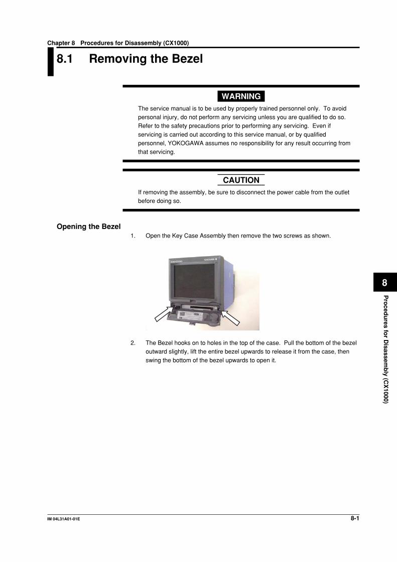
8-1IM 04L31A01-01E
Pro
cedu
res for D
isassemb
ly (CX
1000)
8
Chapter 8 Procedures for Disassembly (CX1000)
8.1 Removing the Bezel
WARNINGThe service manual is to be used by properly trained personnel only. To avoidpersonal injury, do not perform any servicing unless you are qualified to do so.Refer to the safety precautions prior to performing any servicing. Even if
servicing is carried out according to this service manual, or by qualifiedpersonnel, YOKOGAWA assumes no responsibility for any result occurring fromthat servicing.
CAUTIONIf removing the assembly, be sure to disconnect the power cable from the outletbefore doing so.
Opening the Bezel1. Open the Key Case Assembly then remove the two screws as shown.
2. The Bezel hooks on to holes in the top of the case. Pull the bottom of the bezeloutward slightly, lift the entire bezel upwards to release it from the case, then
swing the bottom of the bezel upwards to open it.
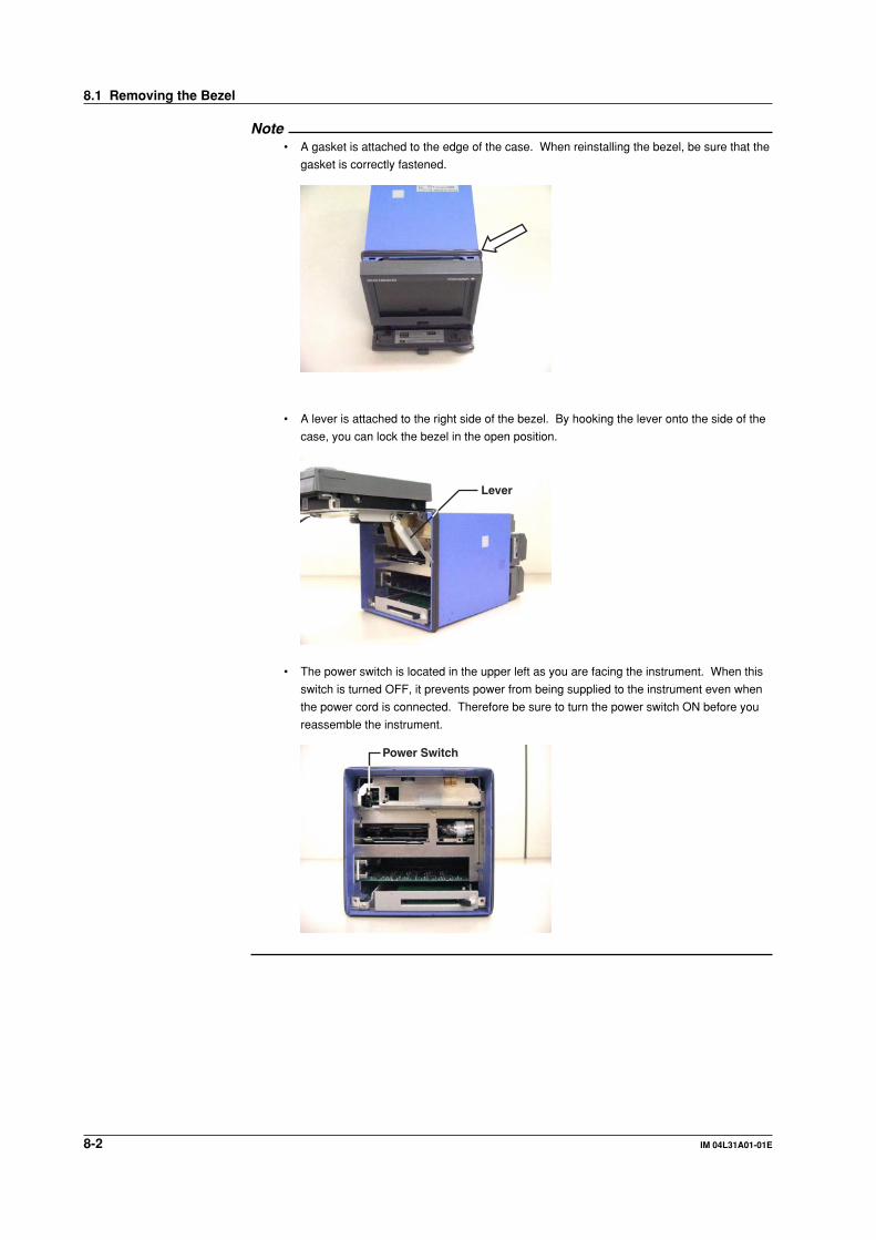
8-2 IM 04L31A01-01E
Note• A gasket is attached to the edge of the case. When reinstalling the bezel, be sure that the
gasket is correctly fastened.
• A lever is attached to the right side of the bezel. By hooking the lever onto the side of the
case, you can lock the bezel in the open position.
Lever
• The power switch is located in the upper left as you are facing the instrument. When this
switch is turned OFF, it prevents power from being supplied to the instrument even when
the power cord is connected. Therefore be sure to turn the power switch ON before you
reassemble the instrument.
Power Switch
8.1 Removing the Bezel
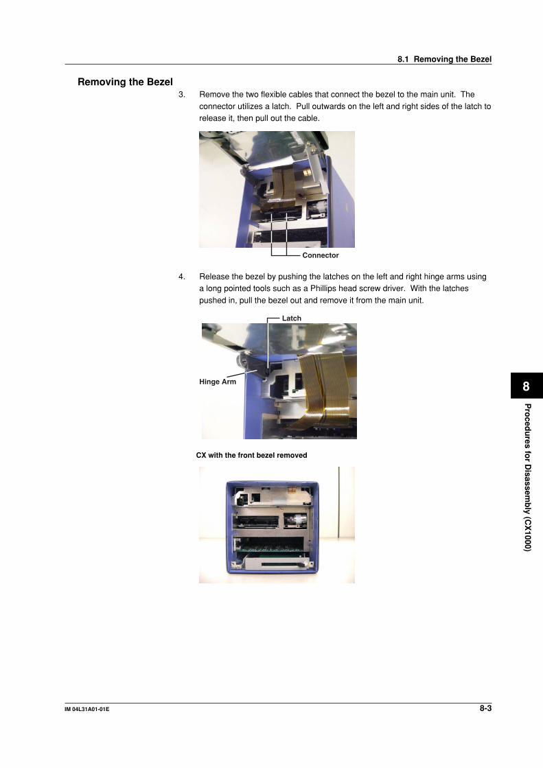
8-3IM 04L31A01-01E
Pro
cedu
res for D
isassemb
ly (CX
1000)
8
Removing the Bezel3. Remove the two flexible cables that connect the bezel to the main unit. The
connector utilizes a latch. Pull outwards on the left and right sides of the latch torelease it, then pull out the cable.
Connector
4. Release the bezel by pushing the latches on the left and right hinge arms usinga long pointed tools such as a Phillips head screw driver. With the latches
pushed in, pull the bezel out and remove it from the main unit.
Latch
Hinge Arm
CX with the front bezel removed
8.1 Removing the Bezel
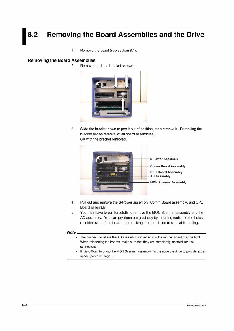
8-4 IM 04L31A01-01E
8.2 Removing the Board Assemblies and the Drive
1. Remove the bezel (see section 8.1).
Removing the Board Assemblies2. Remove the three bracket screws.
3. Slide the bracket down to pop it out of position, then remove it. Removing thebracket allows removal of all board assemblies.CX with the bracket removed.
MON Scanner Assembly
AD AssemblyCPU Board Assembly
S-Power Assembly
Comm Board Assembly
4. Pull out and remove the S-Power assembly, Comm Board assembly, and CPUBoard assembly.
5. You may have to pull forcefully to remove the MON Scanner assembly and the
AD assembly. You can pry them out gradually by inserting tools into the holeson either side of the board, then rocking the board side to side while pulling.
Note• The connection where the AD assembly is inserted into the mother board may be tight.
When reinserting the boards, make sure that they are completely inserted into the
connectors.
• If it is difficult to grasp the MON Scanner assembly, first remove the drive to provide extra
space (see next page).
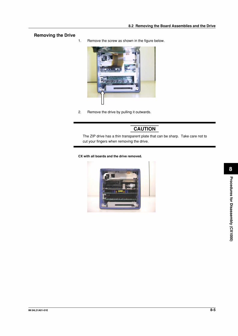
8-5IM 04L31A01-01E
Pro
cedu
res for D
isassemb
ly (CX
1000)
8
Removing the Drive1. Remove the screw as shown in the figure below.
2. Remove the drive by pulling it outwards.
CAUTIONThe ZIP drive has a thin transparent plate that can be sharp. Take care not tocut your fingers when removing the drive.
CX with all boards and the drive removed.
8.2 Removing the Board Assemblies and the Drive
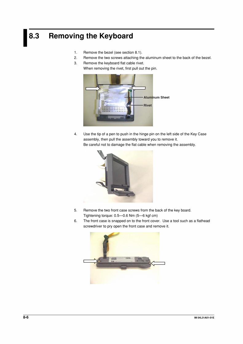
8-6 IM 04L31A01-01E
8.3 Removing the Keyboard
1. Remove the bezel (see section 8.1).2. Remove the two screws attaching the aluminum sheet to the back of the bezel.
3. Remove the keyboard flat cable rivet.When removing the rivet, first pull out the pin.
Rivet
Aluminum Sheet
4. Use the tip of a pen to push in the hinge pin on the left side of the Key Caseassembly, then pull the assembly toward you to remove it.Be careful not to damage the flat cable when removing the assembly.
5. Remove the two front case screws from the back of the key board.Tightening torque: 0.5—0.6 Nm (5—6 kgf cm)
6. The front case is snapped on to the front cover. Use a tool such as a flathead
screwdriver to pry open the front case and remove it.
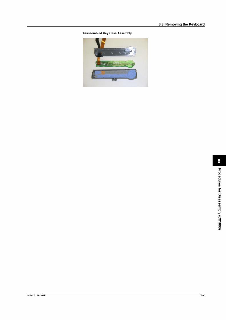
8-7IM 04L31A01-01E
Pro
cedu
res for D
isassemb
ly (CX
1000)
8
Disassembled Key Case Assembly
8.3 Removing the Keyboard
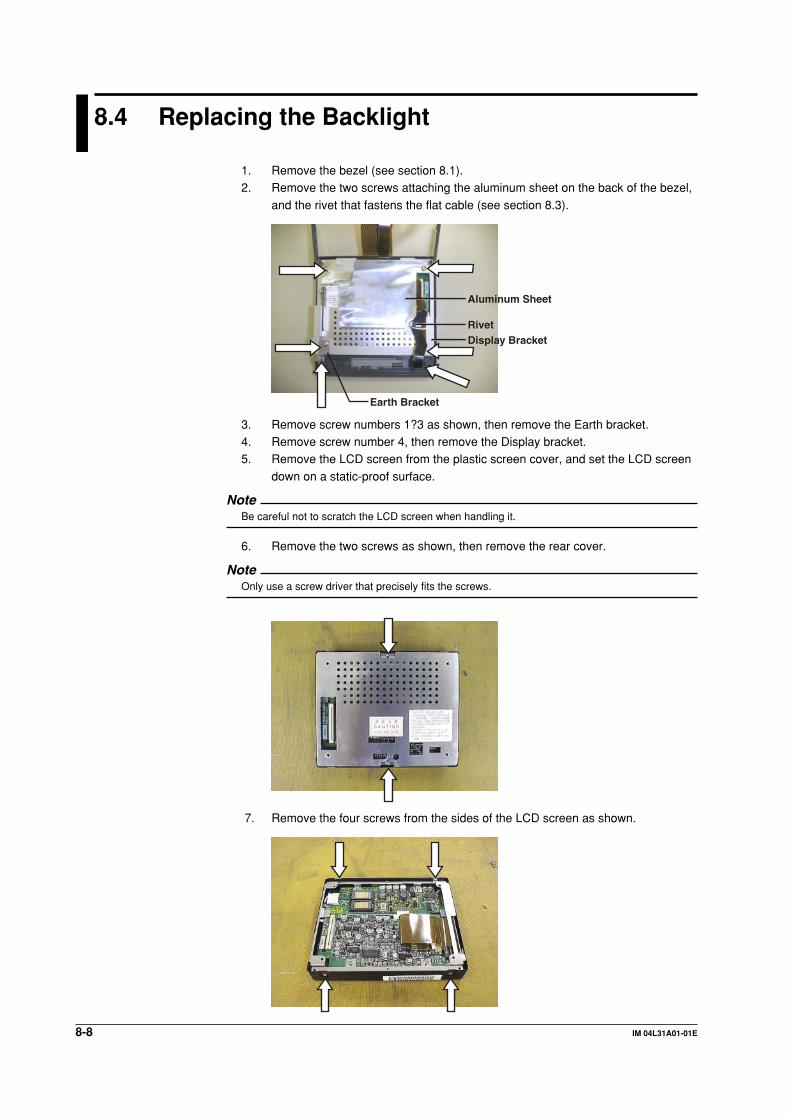
8-8 IM 04L31A01-01E
8.4 Replacing the Backlight
1. Remove the bezel (see section 8.1).2. Remove the two screws attaching the aluminum sheet on the back of the bezel,
and the rivet that fastens the flat cable (see section 8.3).
RivetDisplay Bracket
Aluminum Sheet
Earth Bracket
3. Remove screw numbers 1?3 as shown, then remove the Earth bracket.4. Remove screw number 4, then remove the Display bracket.5. Remove the LCD screen from the plastic screen cover, and set the LCD screen
down on a static-proof surface.
NoteBe careful not to scratch the LCD screen when handling it.
6. Remove the two screws as shown, then remove the rear cover.
NoteOnly use a screw driver that precisely fits the screws.
7. Remove the four screws from the sides of the LCD screen as shown.
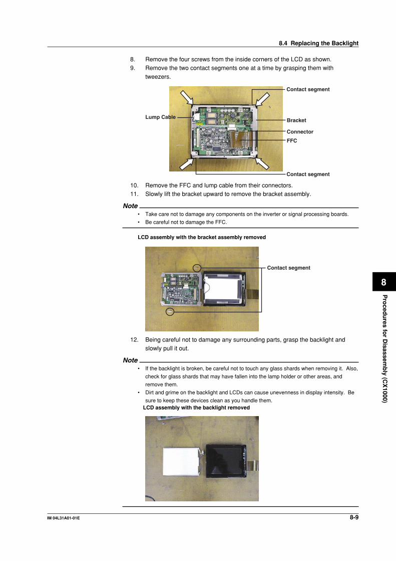
8-9IM 04L31A01-01E
Pro
cedu
res for D
isassemb
ly (CX
1000)
8
8. Remove the four screws from the inside corners of the LCD as shown.9. Remove the two contact segments one at a time by grasping them with
tweezers.
Lump CableBracket
Connector
FFC
Contact segment
Contact segment
10. Remove the FFC and lump cable from their connectors.11. Slowly lift the bracket upward to remove the bracket assembly.
Note• Take care not to damage any components on the inverter or signal processing boards.
• Be careful not to damage the FFC.
LCD assembly with the bracket assembly removed
Contact segment
12. Being careful not to damage any surrounding parts, grasp the backlight andslowly pull it out.
Note• If the backlight is broken, be careful not to touch any glass shards when removing it. Also,
check for glass shards that may have fallen into the lamp holder or other areas, and
remove them.
• Dirt and grime on the backlight and LCDs can cause unevenness in display intensity. Be
sure to keep these devices clean as you handle them.LCD assembly with the backlight removed
8.4 Replacing the Backlight

8-10 IM 04L31A01-01E
8.5 Removing the Terminal Assembly
WARNINGThe service manual is to be used by properly trained personnel only. To avoidpersonal injury, do not perform any servicing unless you are qualified to do so.Refer to the safety precautions prior to performing any servicing. Even if
servicing is carried out according to this service manual, or by qualifiedpersonnel, YOKOGAWA assumes no responsibility for any result occurring fromthat servicing.
CAUTIONWhen removing the assembly, be sure to disconnect the power cable from theoutlet before doing so.
1. Remove the screws from the upper right and lower left of the two terminal
assemblies.
2. Pull out the terminal assemblies.