Embed Size (px)
Citation preview
DARE Page 1
Distance Aware Relaying Energy-efficient:DARE to Monitor Patients in Multi-hop
Body Area Sensor Networks
Prepared by:Anum Tauqir

DARE Page 2
Outline Overview
Problem Statement
Motivation
Brief Overview of M-ATTEMPT and DARE
DARE
DARE Scenarios
Communication Flow
Differences and Similarities
Simulation Results
Conclusion

DARE Page 3
Overview

DARE Page 4
In medical field:
WBAN makes use of the tiny sensors for detecting and monitoring
different biological characteristics of a human body.
The sensors can either be:
in-vivo
wearable

DARE Page 5
Problem Statement

DARE Page 6
Major concerns for BANs:
minimizing energy consumption of the nodes
enhancing network lifetime
enhancing stability period of the network
maximizing throughput
minimizing delay

DARE Page 7
Motivation

DARE Page 8
Monitoring different organs of a human body for detecting
an ailment or any disorder.
The proposed protocol DARE aims:
to improve the deficiencies in a BAN protocol of M-ATTEMPT
namely,
minimum stability period
minimum network lifetime
high energy consumption
low throughput

DARE Page 9
Brief Overview ofM-ATTEMPT and DARE

DARE Page 10
M-ATTEMPTa heterogeneous protocol named as, Mobility-supporting Adaptive Threshold-based Thermal-aware Energy-efficient Multi-hop ProTocol
DAREa heterogeneous protocol named as, Distance Aware Relaying Energy-efficient Protocol to Monitor Patients in Multi-hop Body Area Sensor Networks

DARE Page 11
DARE

DARE Page 12
Ward dimensions - 40 x 20 ft2
Five scenarios
Eight beds
Seven sensors measuring parameters
LOS communication
Network Topology

DARE Page 13
Classification of Body Sensors

DARE Page 14
Energy Model
Parameter Value
ETXelec 16.7 nJ/bit
ERXelec 36.1 nJ/bit
Eamp (3.8) 1.97 nJ/bit
Eamp (5.9) 7.99 nJ/bit
w 4000 bits

DARE Page 15
Equations
Etx(k,d) = ETXelec * k + Eamp(n) * k * dn
Erx(k) = ERXelec * k
Transmitter Energy
Receiver Energy

DARE Page 16
Protocol’s Patient

DARE Page 17
DARE Scenarios

DARE Page 18
Scenario-1
The BSs on each patient carry information and transmit to their respective BR which, then aggregates and relay the received data to the sink located at the center of the
ward. The communication flow is from BSs to BR to Sink.

DARE Page 19
Scenario-2
Four sinks have been used that are separately deployed in the middle of the walls of the ward. The BSs of each patient, on sensing the vital sign transmit data to their
respective BR. The BR checks for the nearest sink by calculating it’s distance with each sink. Whichever, sink is found nearest, the BR communicates with that particular sink. The communication flow is from BSs to BR to nearest Sink (Sink1 or Sink2 or Sink3 or
Sink4).

DARE Page 20
Scenario-3
MS is incorporated on each bed which, can be a PDA type device. The deployment of MS helps the BR to consume little energy as, BR transmits data over shorter distance.
However, this scenario increases the delay in the network, as the data traverses through a long route towards the destination node, the Sink. Communication flow is
from BSs to BR to MS to Sink.

DARE Page 21
Scenario-4
It follows the same communication flow as sceanrio-1, however, now the sink is made mobile which, moves along the center of ward.
DARE Page 22
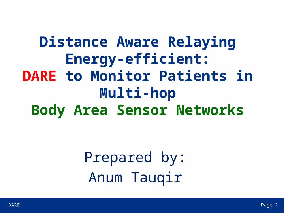
Scenario-5
Multiple sinks move around the walls of the ward altogether. In this scenario also, each BR measures it’s distance with each sink. Whosoever is found close, the BR starts communicating with that sink. The communication flow is from BSs to BR to the
nearest moving Sink (Sink1 or Sink2 or Sink3 or Sink4).

DARE Page 23
Communication Flow

DARE Page 24

DARE Page 25
Differences and Similarities
• DARE• M-ATTEMPT

DARE Page 26
Parameter DARE M-ATTEMPTTypes of devices Body Sensors (BSs), Body Relay (BR),
Main Sensor (MS), SinkSensors, Sink
Deployment BSs, BRs and MS are fixedSink can either be static or mobile
Sensors and Sink bothare fixed
Topology per patient 7 BSs1 BR on chest
7 Sensors1 Sink on chest
Communication flow Depending upon scenario Sensors to Sinkor Sensors to other Sensorsto Sink
Energy parameters E0BSs = 0.3 JE0BR = 1 JEMS = infiniteESink = infinite
E0Sensors = 0.3 JESink = infinite
Network type Heterogeneous in terms of energy of BSs and BRs
Homogeneous interms of energy of Sensors
Communication type Multi-hop Single-hopMulti-hop
Types of data reporting Event-drivenTime-driven
Event-drivenTime-driven

DARE Page 27
Simulation Results
DARE Page 28
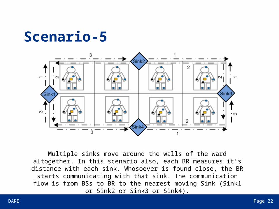
Alive Nodes (BSs and Sensors)
Number of remaining alive nodes (BSs) in the network
0 500 1000 1500 2000 2500 3000 3500 4000 4500 50000
10
20
30
40
50
Number of Rounds (r)
Num
ber
of A
live
(BS
s)
M-ATTEMPT AliveDARE Alive

DARE Page 29
Alive Nodes (BSs, BRs and Sensors)
Number of remaining alive nodes (BSs + BRs) in the network
0 500 1000 1500 2000 2500 3000 3500 4000 4500 50000
10
20
30
40
50
60
Number of Rounds (r)
Num
ber
of A
live
node
s (B
Ss
+ B
Rs)
Scene1-AliveScene2-AliveScene3-AliveScene4-AliveScene5-AliveM-ATTEMPT-Alive

DARE Page 30
Residual Energy
Residual energy (BSs) of the network
0 500 1000 1500 2000 2500 3000 3500 4000 4500 50000
0.05
0.1
0.15
0.2
0.25
Number of Rounds (r)
Res
idua
l Ene
rgy
of B
Ss
(J)
M-ATTEMPT-EnergyDARE-Energy

DARE Page 31
Packets Sent to Sink
Number of packets sent to sink
DARE Page 32
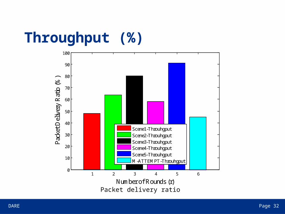
Throughput (%)
Packet delivery ratio
1 2 3 4 5 60
10
20
30
40
50
60
70
80
90
100
Number of Rounds (r)
Pac
ket D
eliv
ery
Rat
io (
%)
Scene1-ThrouhgputScene2-ThrouhgputScene3-ThrouhgputScene4-ThrouhgputScene5-ThrouhgputM-ATTEMPT-Throuhgput

DARE Page 33
Conclusion
DARE Page 34
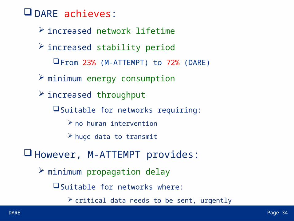
DARE achieves:
increased network lifetime
increased stability period
From 23% (M-ATTEMPT) to 72% (DARE)
minimum energy consumption
increased throughput
Suitable for networks requiring:
no human intervention
huge data to transmit
However, M-ATTEMPT provides:
minimum propagation delay
Suitable for networks where:
critical data needs to be sent, urgently

DARE Page 35
Comparison results between DARE and M-ATTEMPT
Parameter DARE M-ATTEMPT
Stability period high low
Network lifetime high low
Energy consumption minimum maximum
Throughput high low
Propagation delay high low

DARE Page 36