Embed Size (px)
Citation preview

DARPA MMW System programs and how they drive technology needs
H. Bruce [email protected]
DMRC Millimeter-Wave Technology WorkshopOctober 30th, 2014
Approved for Public Release, Distribution Unlimited
2
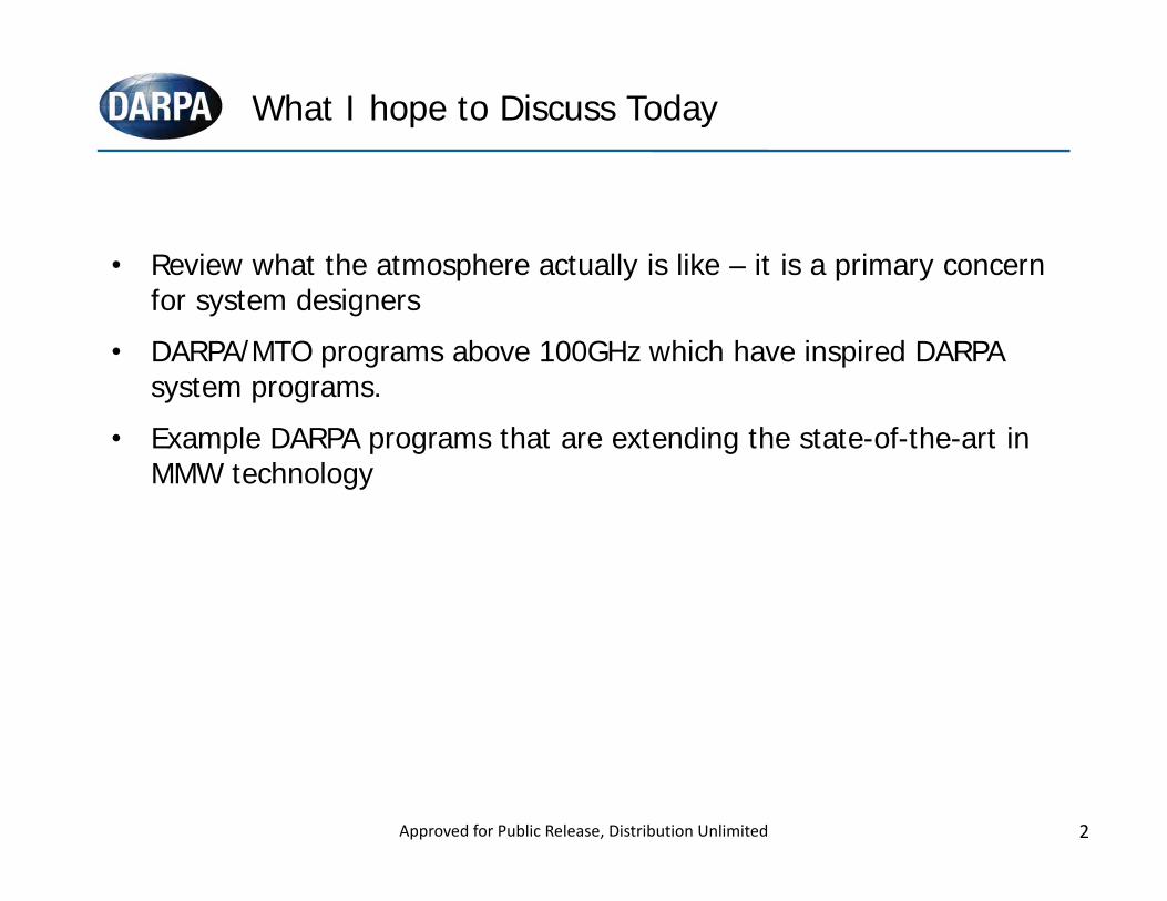
• Review what the atmosphere actually is like – it is a primary concern for system designers
• DARPA/MTO programs above 100GHz which have inspired DARPA system programs.
• Example DARPA programs that are extending the state-of-the-art in MMW technology
What I hope to Discuss Today
Approved for Public Release, Distribution Unlimited
3
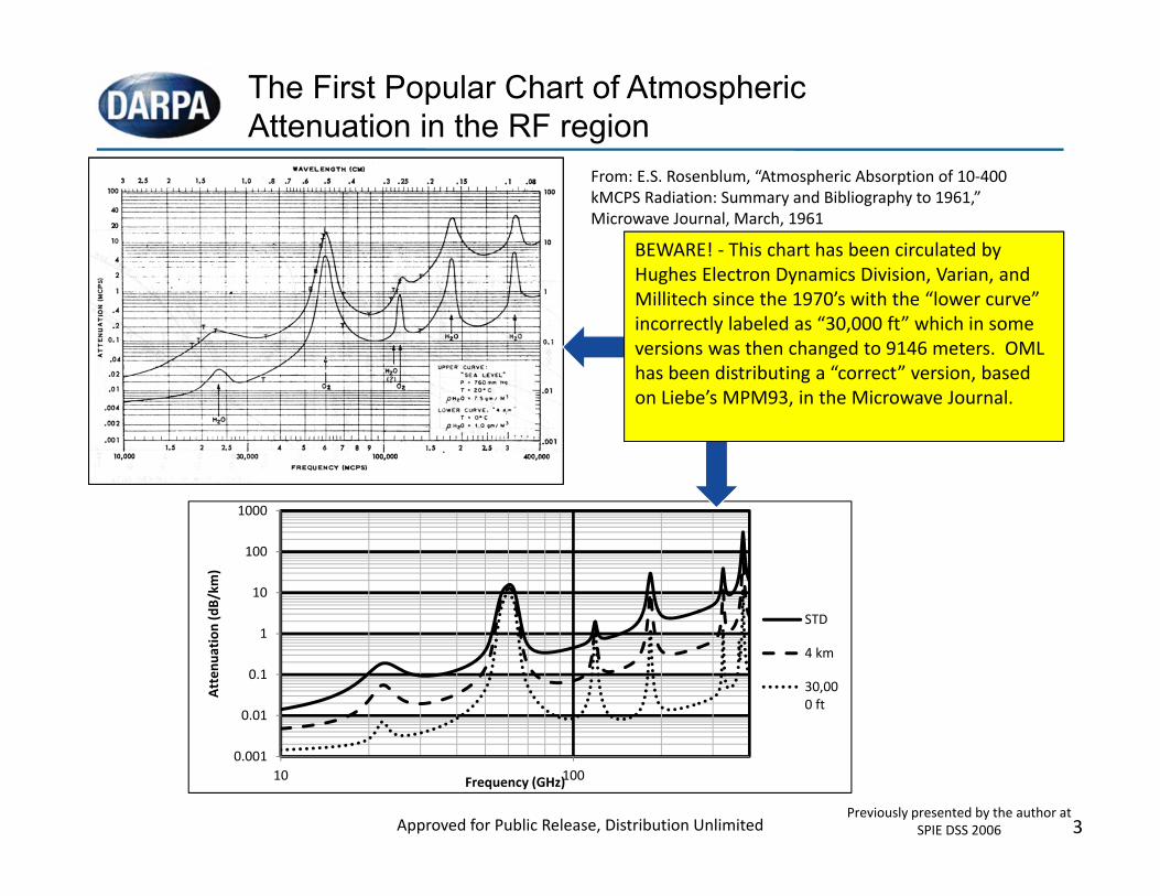
The First Popular Chart of Atmospheric Attenuation in the RF region
From: E.S. Rosenblum, “Atmospheric Absorption of 10‐400 kMCPS Radiation: Summary and Bibliography to 1961,” Microwave Journal, March, 1961
0.001
0.01
0.1
1
10
100
1000
10 100
Attenu
ation (dB/km
)
Frequency (GHz)
STD
4 km
30,000 ft
BEWARE! ‐ This chart has been circulated by Hughes Electron Dynamics Division, Varian, and Millitech since the 1970’s with the “lower curve” incorrectly labeled as “30,000 ft” which in some versions was then changed to 9146 meters. OML has been distributing a “correct” version, based on Liebe’s MPM93, in the Microwave Journal.
Approved for Public Release, Distribution UnlimitedPreviously presented by the author at
SPIE DSS 2006
4
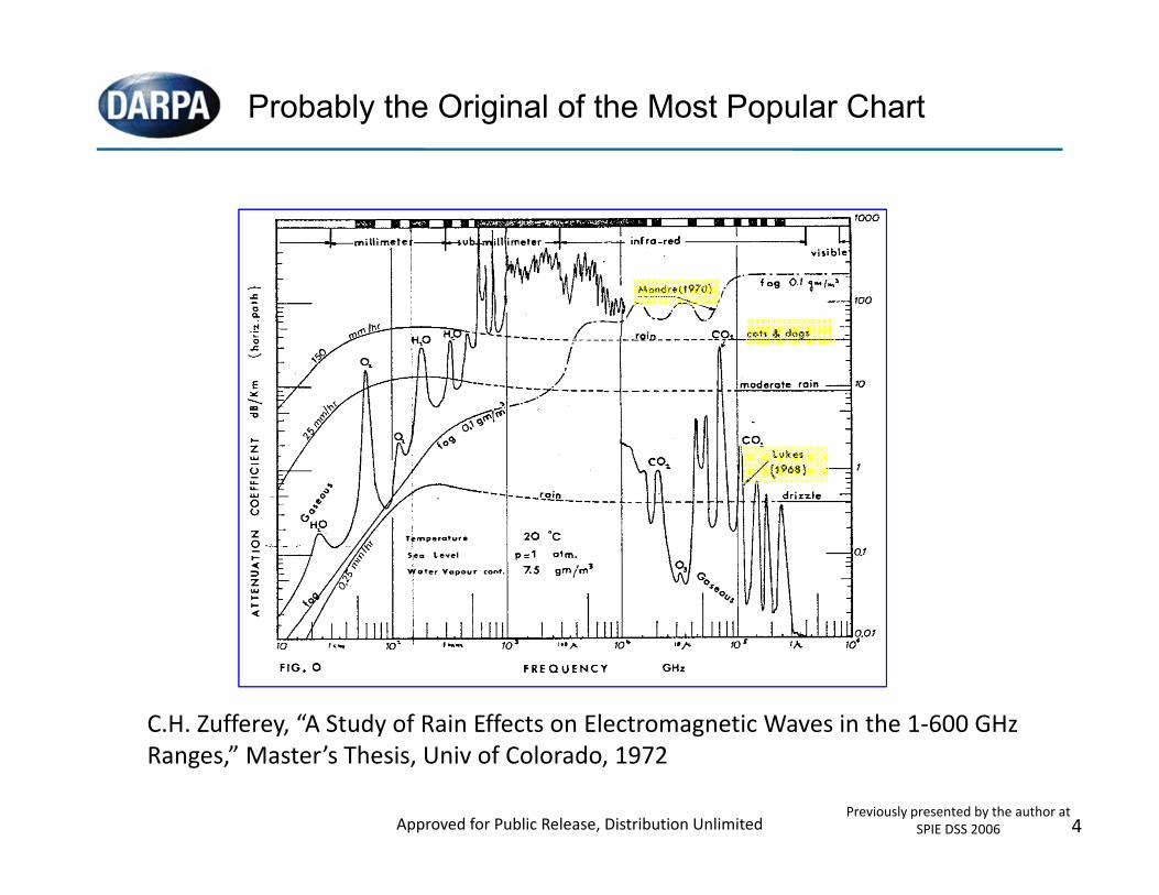
Probably the Original of the Most Popular Chart
C.H. Zufferey, “A Study of Rain Effects on Electromagnetic Waves in the 1‐600 GHz Ranges,” Master’s Thesis, Univ of Colorado, 1972
Approved for Public Release, Distribution UnlimitedPreviously presented by the author at
SPIE DSS 2006
5
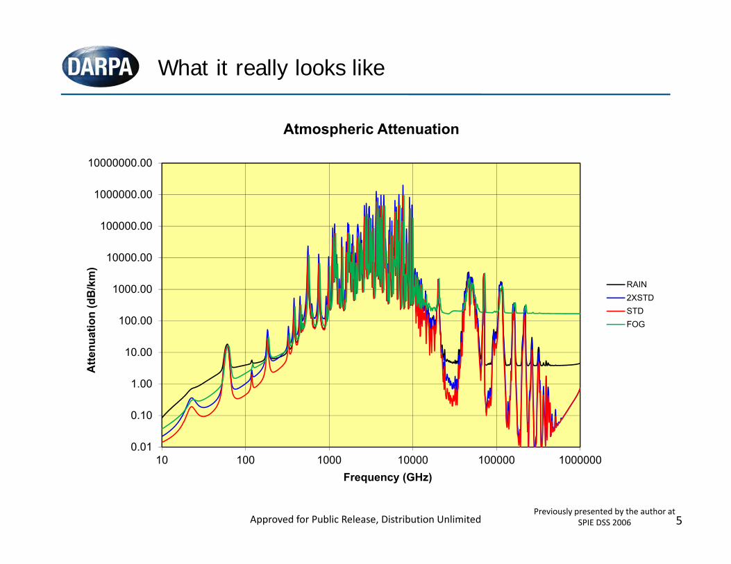
What it really looks like
0.01
0.10
1.00
10.00
100.00
1000.00
10000.00
100000.00
1000000.00
10000000.00
10 100 1000 10000 100000 1000000
Atte
nuat
ion
(dB
/km
)
Frequency (GHz)
Atmospheric Attenuation
RAIN2XSTDSTDFOG
Approved for Public Release, Distribution UnlimitedPreviously presented by the author at
SPIE DSS 2006
6
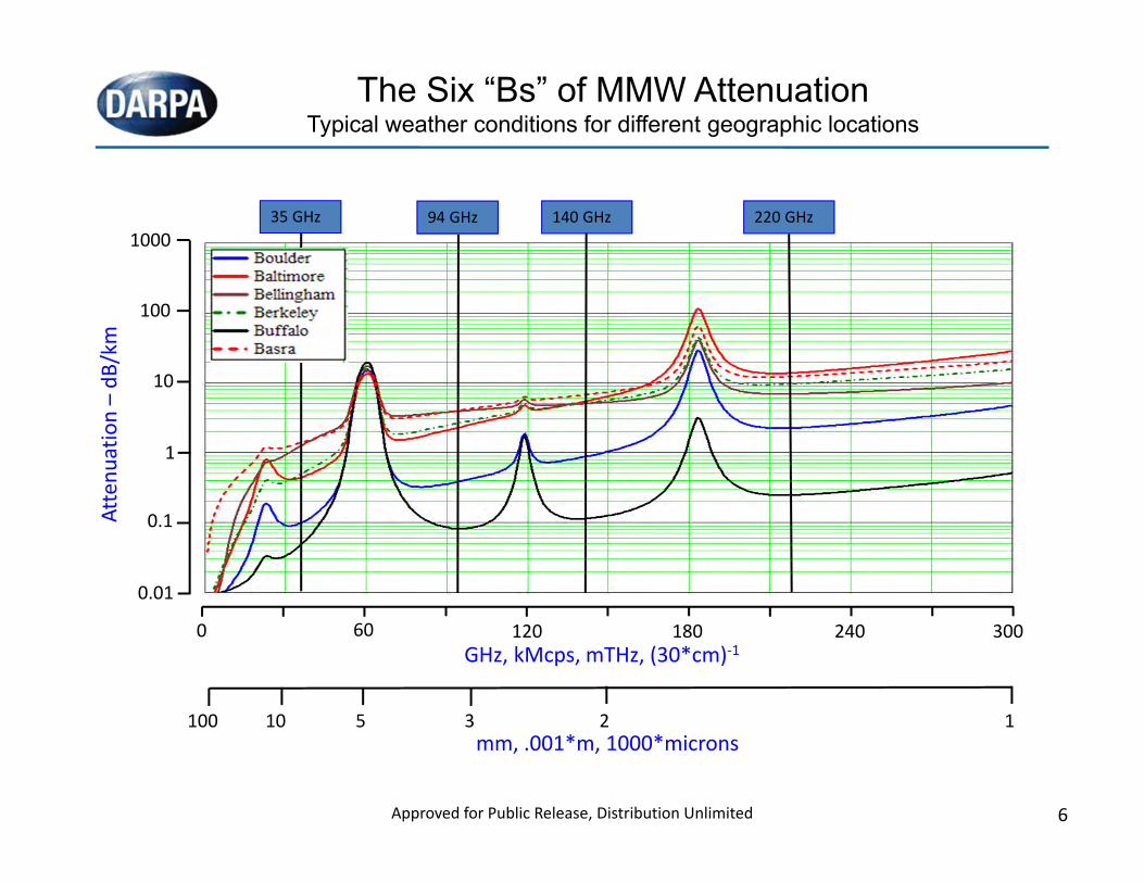
The Six “Bs” of MMW AttenuationTypical weather conditions for different geographic locations
0 60 120 180 240 300GHz, kMcps, mTHz, (30*cm)‐1
mm, .001*m, 1000*microns110 2100 35
1000
100
10
1
0.1
0.01
Attenu
ation –dB
/km
35 GHz 94 GHz 140 GHz 220 GHz
Approved for Public Release, Distribution Unlimited
7
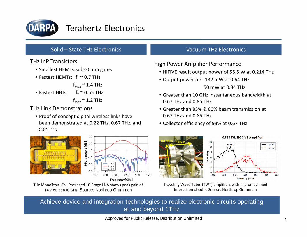
Terahertz Electronics
THz Monolithic ICs: Packaged 10‐Stage LNA shows peak gain of 14.7 dB at 830 GHz. Source: Northrop Grumman
Achieve device and integration technologies to realize electronic circuits operatingat and beyond 1THz
THz InP Transistors• Smallest HEMTs:sub‐30 nm gates• Fastest HEMTs: fT ~ 0.7 THz
fmax ~ 1.4 THz• Fastest HBTs: fT ~ 0.55 THz
fmax ~ 1.2 THzTHz Link Demonstrations
• Proof of concept digital wireless links have been demonstrated at 0.22 THz, 0.67 THz, and 0.85 THz
Solid – State THz Electronics Vacuum THz Electronics
High Power Amplifier Performance• HiFIVE result output power of 55.5 W at 0.214 THz• Output power of: 132 mW at 0.64 THz
50 mW at 0.84 THz• Greater than 10 GHz instantaneous bandwidth at0.67 THz and 0.85 THz
• Greater than 83% & 60% beam transmission at0.67 THz and 0.85 THz
• Collector efficiency of 93% at 0.67 THz
Traveling Wave Tube (TWT) amplifiers with micromachined interaction circuits. Source: Northrop Grumman
Approved for Public Release, Distribution Unlimited
8
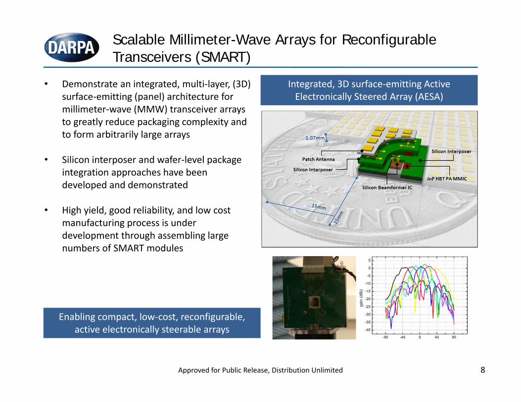
Scalable Millimeter-Wave Arrays for Reconfigurable Transceivers (SMART)
Enabling compact, low‐cost, reconfigurable, active electronically steerable arrays
Integrated, 3D surface‐emitting Active Electronically Steered Array (AESA)
(Pout = 5 W/cm2)
• Demonstrate an integrated, multi‐layer, (3D) surface‐emitting (panel) architecture for millimeter‐wave (MMW) transceiver arrays to greatly reduce packaging complexity and to form arbitrarily large arrays
• Silicon interposer and wafer‐level package integration approaches have been developed and demonstrated
• High yield, good reliability, and low cost manufacturing process is under development through assembling large numbers of SMART modules
Approved for Public Release, Distribution Unlimited
9
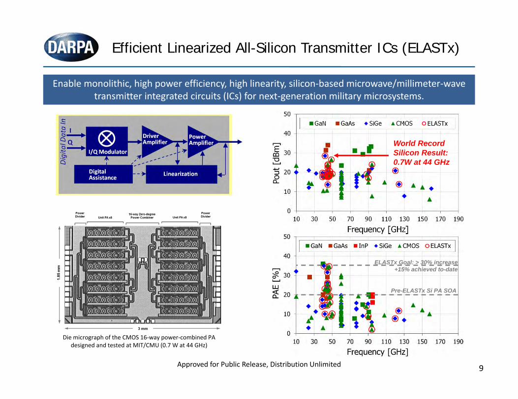
Efficient Linearized All-Silicon Transmitter ICs (ELASTx)
Approved for Public Release, Distribution Unlimited
Enable monolithic, high power efficiency, high linearity, silicon‐based microwave/millimeter‐wave transmitter integrated circuits (ICs) for next‐generation military microsystems.
Die micrograph of the CMOS 16‐way power‐combined PA designed and tested at MIT/CMU (0.7 W at 44 GHz)
Pre-ELASTx Si PA SOA
World Record Silicon Result:0.7W at 44 GHz
ELASTx Goal: > 30% increase+15% achieved to-date
10
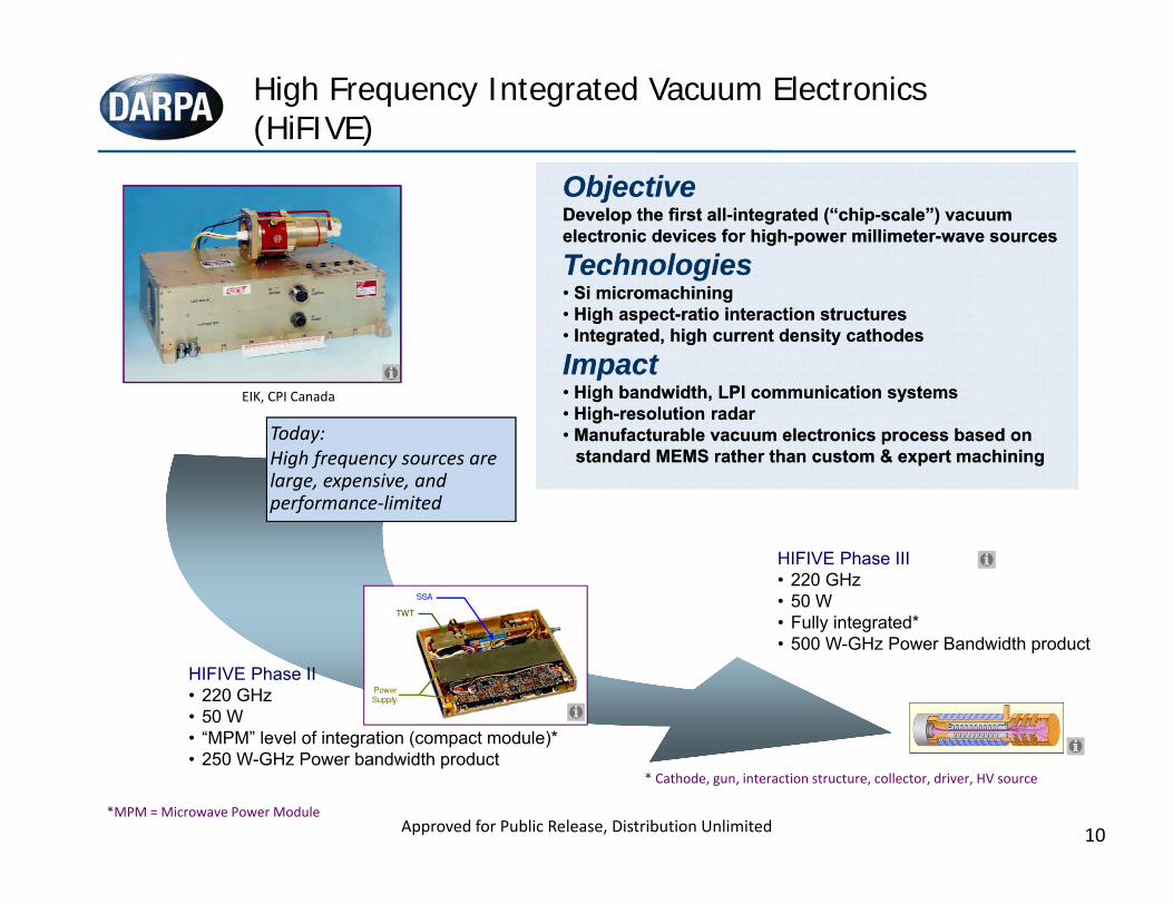
High Frequency Integrated Vacuum Electronics (HiFIVE)
Approved for Public Release, Distribution Unlimited
ObjectiveDevelop the first all-integrated (“chip-scale”) vacuum electronic devices for high-power millimeter-wave sources
Technologies• Si micromachining• High aspect-ratio interaction structures• Integrated, high current density cathodes
Impact• High bandwidth, LPI communication systems• High-resolution radar• Manufacturable vacuum electronics process based on
standard MEMS rather than custom & expert machining
HIFIVE Phase II• 220 GHz• 50 W• “MPM” level of integration (compact module)*• 250 W-GHz Power bandwidth product
HIFIVE Phase III• 220 GHz• 50 W• Fully integrated*• 500 W-GHz Power Bandwidth product
EIK, CPI Canada
Today:High frequency sources are large, expensive, and performance‐limited
*MPM = Microwave Power Module
* Cathode, gun, interaction structure, collector, driver, HV source
11
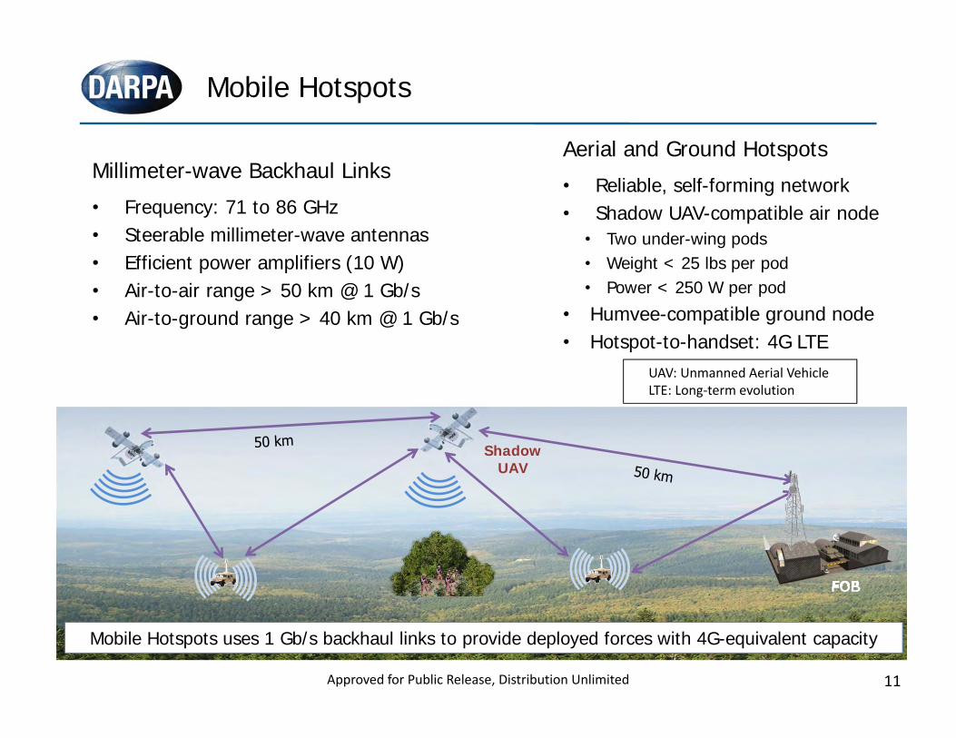
Millimeter-wave Backhaul Links• Frequency: 71 to 86 GHz• Steerable millimeter-wave antennas• Efficient power amplifiers (10 W)• Air-to-air range > 50 km @ 1 Gb/s• Air-to-ground range > 40 km @ 1 Gb/s
Mobile Hotspots
Aerial and Ground Hotspots• Reliable, self-forming network• Shadow UAV-compatible air node
• Two under-wing pods• Weight < 25 lbs per pod• Power < 250 W per pod
• Humvee-compatible ground node• Hotspot-to-handset: 4G LTE
FOB/PRTFOB
Shadow UAV
Mobile Hotspots uses 1 Gb/s backhaul links to provide deployed forces with 4G-equivalent capacity
UAV: Unmanned Aerial VehicleLTE: Long‐term evolution
Approved for Public Release, Distribution Unlimited
12
5
10
15
20
25
30
35
0.01 0.1 1 10 100Pow
er A
dded
Eff
icie
ncy
(%)
Output Power (W)
GaN HEMT
InP HEMT
GaAs pHEMT
HRL GaN T2
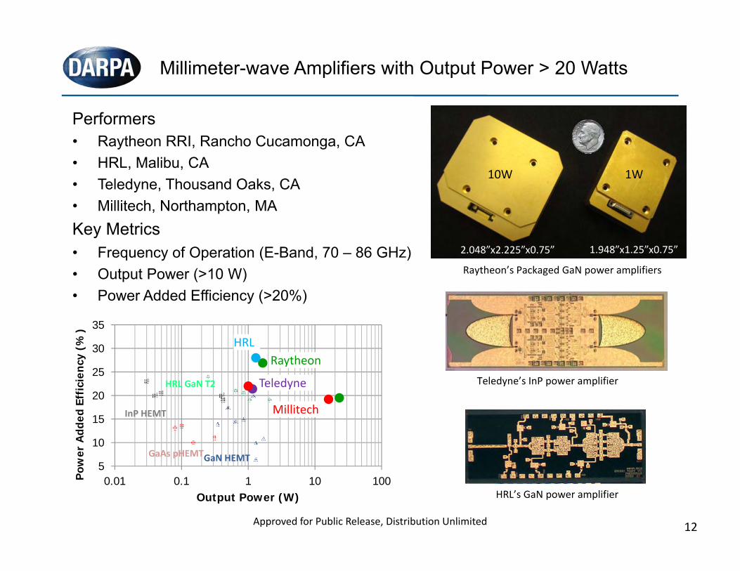
Performers• Raytheon RRI, Rancho Cucamonga, CA• HRL, Malibu, CA• Teledyne, Thousand Oaks, CA• Millitech, Northampton, MAKey Metrics• Frequency of Operation (E-Band, 70 – 86 GHz)• Output Power (>10 W)• Power Added Efficiency (>20%)
Millimeter-wave Amplifiers with Output Power > 20 Watts
Approved for Public Release, Distribution Unlimited
1.948”x1.25”x0.75”2.048”x2.225”x0.75”
10W 1W
HRL’s GaN power amplifier
Teledyne’s InP power amplifier
Raytheon’s Packaged GaN power amplifiers
5
10
15
20
25
30
35
0.01 0.1 1 10 100Pow
er A
dded
Eff
icie
ncy
(%)
Output Power (W)
GaN HEMT
InP HEMT
GaAs pHEMT
HRL GaN T2
5
10
15
20
25
30
35
0.01 0.1 1 10 100Pow
er A
dded
Eff
icie
ncy
(%)
Output Power (W)
GaN HEMT
InP HEMT
GaAs pHEMT
HRL GaN T2
5
10
15
20
25
30
35
0.01 0.1 1 10 100Pow
er A
dded
Eff
icie
ncy
(%)
Output Power (W)
GaN HEMT
InP HEMT
GaAs pHEMT
HRL GaN T2
5
10
15
20
25
30
35
0.01 0.1 1 10 100Pow
er A
dded
Eff
icie
ncy
(%)
Output Power (W)
GaN HEMT
InP HEMT
GaAs pHEMT
HRL GaN T2
5
10
15
20
25
30
35
0.01 0.1 1 10 100Pow
er A
dded
Eff
icie
ncy
(%)
Output Power (W)
GaN HEMT
InP HEMT
GaAs pHEMT
HRL GaN T2
Raytheon
Millitech
Teledyne
HRL
13
Distribution Statement13
11/3/2014
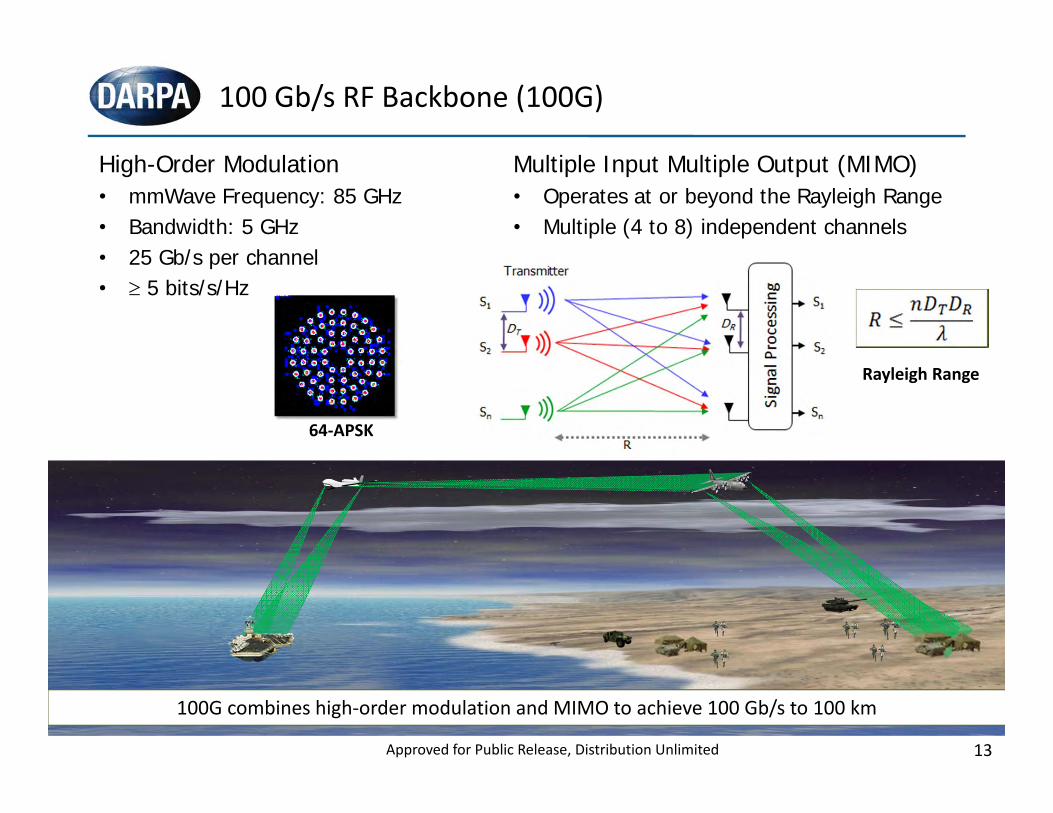
100 Gb/s RF Backbone (100G)
100G combines high‐order modulation and MIMO to achieve 100 Gb/s to 100 km
Distribution Statement C: Distribution authorized to U.S. Government agencies and their contractorsApproved for Public Release, Distribution Unlimited
High-Order Modulation• mmWave Frequency: 85 GHz• Bandwidth: 5 GHz• 25 Gb/s per channel• 5 bits/s/Hz
Multiple Input Multiple Output (MIMO)• Operates at or beyond the Rayleigh Range• Multiple (4 to 8) independent channels
64‐APSK
Rayleigh Range
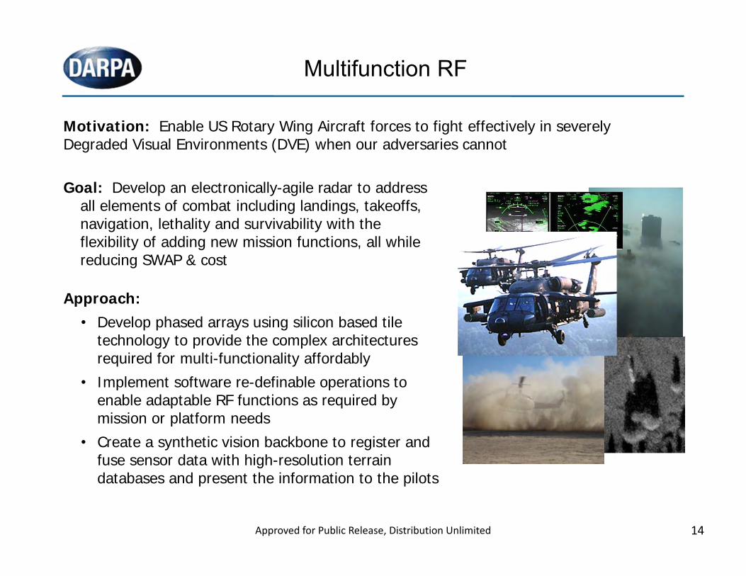
Multifunction RF
Goal: Develop an electronically-agile radar to address all elements of combat including landings, takeoffs, navigation, lethality and survivability with the flexibility of adding new mission functions, all while reducing SWAP & cost
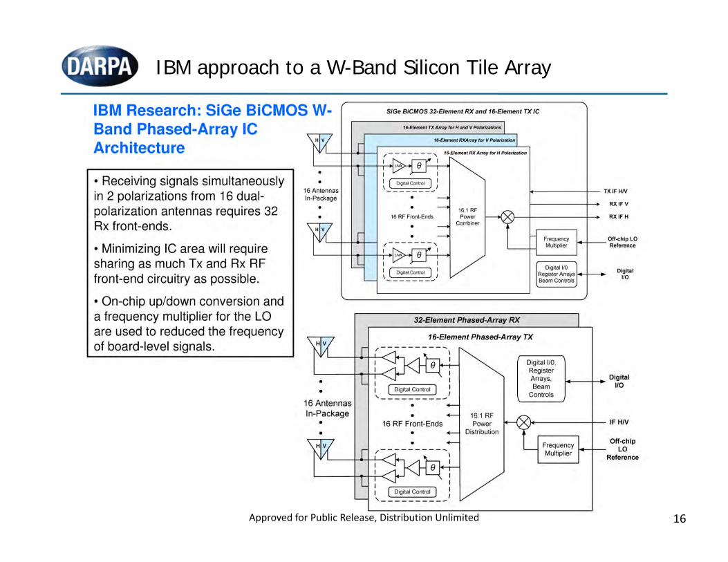
Approach:• Develop phased arrays using silicon based tile
technology to provide the complex architectures required for multi-functionality affordably
• Implement software re-definable operations to enable adaptable RF functions as required by mission or platform needs
• Create a synthetic vision backbone to register and fuse sensor data with high-resolution terrain databases and present the information to the pilots
Motivation: Enable US Rotary Wing Aircraft forces to fight effectively in severely Degraded Visual Environments (DVE) when our adversaries cannot
14Approved for Public Release, Distribution Unlimited
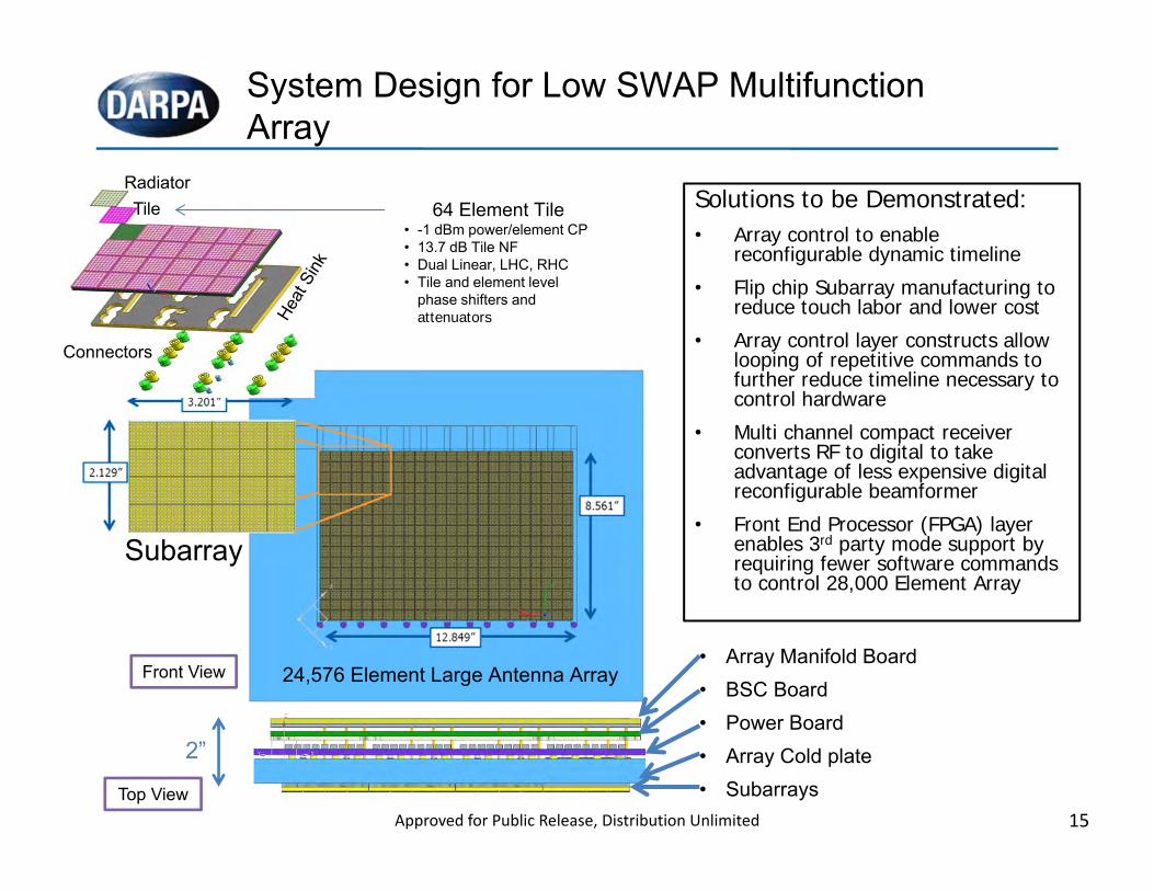
System Design for Low SWAP Multifunction Array
Solutions to be Demonstrated:• Array control to enable
reconfigurable dynamic timeline • Flip chip Subarray manufacturing to
reduce touch labor and lower cost• Array control layer constructs allow
looping of repetitive commands to further reduce timeline necessary to control hardware
• Multi channel compact receiver converts RF to digital to take advantage of less expensive digital reconfigurable beamformer
• Front End Processor (FPGA) layer enables 3rd party mode support by requiring fewer software commands to control 28,000 Element Array
Top View
• Array Manifold Board• BSC Board• Power Board• Array Cold plate• Subarrays
Front View
2”
24,576 Element Large Antenna Array
Subarray
64 Element Tile• -1 dBm power/element CP• 13.7 dB Tile NF• Dual Linear, LHC, RHC• Tile and element level
phase shifters and attenuators
Connectors
TileRadiator
15Approved for Public Release, Distribution Unlimited
16
IBM approach to a W-Band Silicon Tile Array
Approved for Public Release, Distribution Unlimited
17
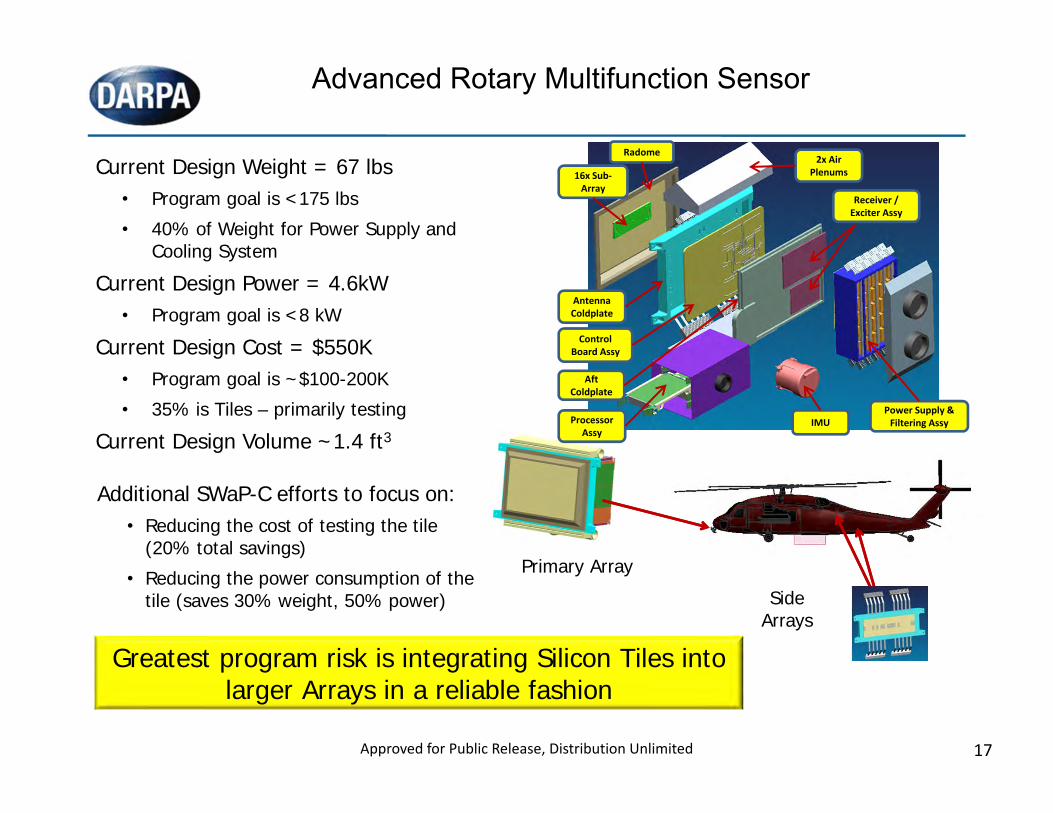
Advanced Rotary Multifunction Sensor
Current Design Weight = 67 lbs• Program goal is <175 lbs• 40% of Weight for Power Supply and
Cooling SystemCurrent Design Power = 4.6kW
• Program goal is <8 kWCurrent Design Cost = $550K
• Program goal is ~$100-200K• 35% is Tiles – primarily testing
Current Design Volume ~1.4 ft3
Additional SWaP-C efforts to focus on:• Reducing the cost of testing the tile
(20% total savings)• Reducing the power consumption of the
tile (saves 30% weight, 50% power) Side Arrays
Primary Array
Greatest program risk is integrating Silicon Tiles into larger Arrays in a reliable fashion
Radome
16x Sub‐Array
2x Air Plenums
Antenna Coldplate
Control Board Assy
Aft Coldplate
Processor Assy
Receiver / Exciter Assy
IMU Power Supply & Filtering Assy
Approved for Public Release, Distribution Unlimited
18
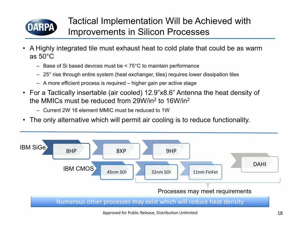
Tactical Implementation Will be Achieved with Improvements in Silicon Processes
8HP 8XP 9HP
45nm SOI 32nm SOI 11nm FinFet
IBM SiGe
IBM CMOS
• A Highly integrated tile must exhaust heat to cold plate that could be as warm as 50°C
– Base of Si based devices must be < 75°C to maintain performance– 25° rise through entire system (heat exchanger, tiles) requires lower dissipation tiles – A more efficient process is required – higher gain per active stage
• For a Tactically insertable (air cooled) 12.9”x8.6” Antenna the heat density of the MMICs must be reduced from 29W/in2 to 16W/in2
– Current 2W 16 element MMIC must be reduced to 1W
• The only alternative which will permit air cooling is to reduce functionality.
Processes may meet requirements
Numerous other processes may exist which will reduce heat density
DAHI
Approved for Public Release, Distribution Unlimited
19
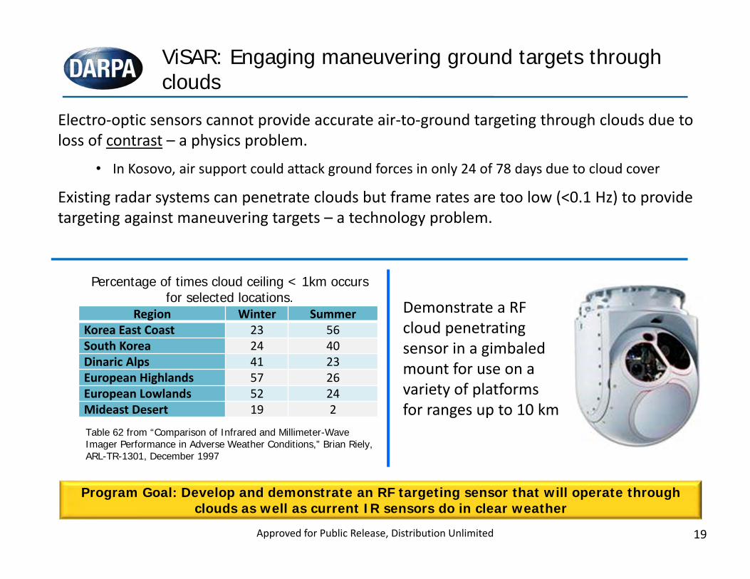
Percentage of times cloud ceiling < 1km occurs for selected locations.
Table 62 from “Comparison of Infrared and Millimeter-Wave Imager Performance in Adverse Weather Conditions,” Brian Riely, ARL-TR-1301, December 1997
ViSAR: Engaging maneuvering ground targets through clouds
Electro‐optic sensors cannot provide accurate air‐to‐ground targeting through clouds due to loss of contrast – a physics problem.
• In Kosovo, air support could attack ground forces in only 24 of 78 days due to cloud cover
Existing radar systems can penetrate clouds but frame rates are too low (<0.1 Hz) to provide targeting against maneuvering targets – a technology problem.
Region Winter SummerKorea East Coast 23 56South Korea 24 40Dinaric Alps 41 23European Highlands 57 26European Lowlands 52 24Mideast Desert 19 2
Program Goal: Develop and demonstrate an RF targeting sensor that will operate through clouds as well as current IR sensors do in clear weather
Demonstrate a RF cloud penetrating sensor in a gimbaled mount for use on a variety of platforms for ranges up to 10 km
Approved for Public Release, Distribution Unlimited
20
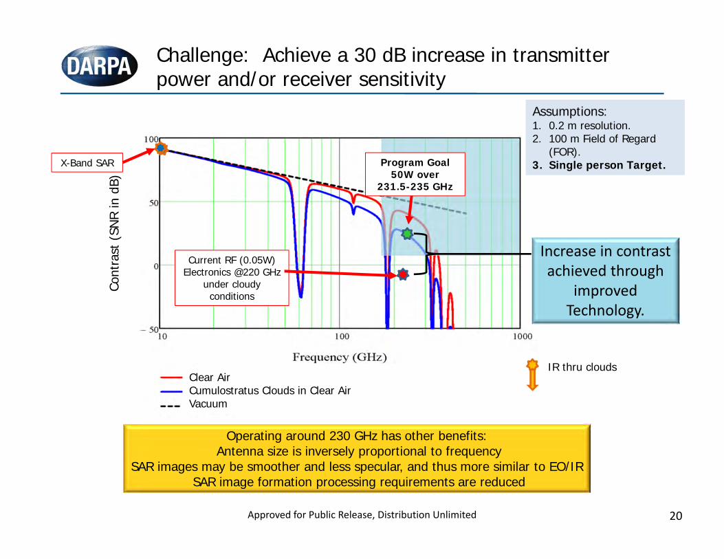
Challenge: Achieve a 30 dB increase in transmitter power and/or receiver sensitivity
Current RF (0.05W) Electronics @220 GHz
under cloudy conditions
Clear AirCumulostratus Clouds in Clear AirVacuum
Cont
rast
(SNR
in d
B)
Program Goal50W over
231.5-235 GHz
Operating around 230 GHz has other benefits:Antenna size is inversely proportional to frequency
SAR images may be smoother and less specular, and thus more similar to EO/IRSAR image formation processing requirements are reduced
Increase in contrast achieved through
improved Technology.
Assumptions:1. 0.2 m resolution.2. 100 m Field of Regard
(FOR).3. Single person Target.
Assumptions:1. 0.2 m resolution.2. 100 m Field of Regard
(FOR).3. Single person Target.X-Band SAR
IR thru clouds
Approved for Public Release, Distribution Unlimited
21
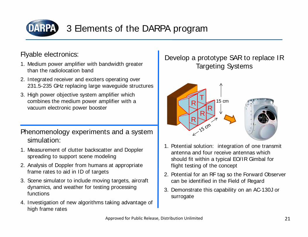
3 Elements of the DARPA program
Flyable electronics:1. Medium power amplifier with bandwidth greater
than the radiolocation band2. Integrated receiver and exciters operating over
231.5-235 GHz replacing large waveguide structures3. High power objective system amplifier which
combines the medium power amplifier with a vacuum electronic power booster
Develop a prototype SAR to replace IR Targeting Systems
1. Potential solution: integration of one transmit antenna and four receive antennas which should fit within a typical EO/IR Gimbal for flight testing of the concept
2. Potential for an RF tag so the Forward Observer can be identified in the Field of Regard
3. Demonstrate this capability on an AC-130J or surrogate
Phenomenology experiments and a system simulation:
1. Measurement of clutter backscatter and Doppler spreading to support scene modeling
2. Analysis of Doppler from humans at appropriate frame rates to aid in ID of targets
3. Scene simulator to include moving targets, aircraft dynamics, and weather for testing processing functions
4. Investigation of new algorithms taking advantage of high frame rates
15 cmTR
RR
R
Approved for Public Release, Distribution Unlimited
22
An opportunity exists to create a new imaging radar architecture which will:• Provide high resolution 3D imaging for enhanced identification and targeting;
independent of platform or target motion• Produce video frame rates (>10 Hz) to compensate for image/target motion• Reduce system complexity resulting in lower cost, power, and weight
ASTIR will result in more readily available, cost effective imaging radar capabilities for:• Terminal homing seekers• Target classification for force protection• Personal imaging for detection of concealed weapons• Other applications ?
Advanced Scanning Technology for Imaging Radars (ASTIR)
ASTIR will exploit recent developments to create a new imaging radar architecture
Approved for Public Release, Distribution Unlimited
23
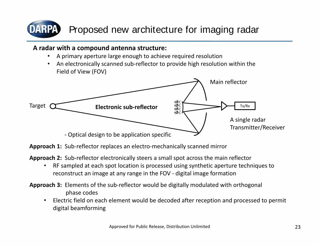
Proposed new architecture for imaging radar
Approach 1: Sub‐reflector replaces an electro‐mechanically scanned mirror
Approach 2: Sub‐reflector electronically steers a small spot across the main reflector• RF sampled at each spot location is processed using synthetic aperture techniques to
reconstruct an image at any range in the FOV ‐ digital image formation
Approach 3: Elements of the sub‐reflector would be digitally modulated with orthogonal phase codes
• Electric field on each element would be decoded after reception and processed to permit digital beamforming
A radar with a compound antenna structure:• A primary aperture large enough to achieve required resolution• An electronically scanned sub‐reflector to provide high resolution within the
Field of View (FOV)
A single radarTransmitter/Receiver
Main reflector
Electronic sub‐reflector
‐ Optical design to be application specific
Target Tx/Rx
Approved for Public Release, Distribution Unlimited
24
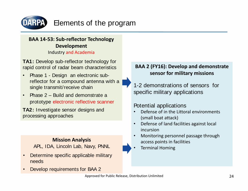
Elements of the program
BAA 14‐53: Sub‐reflector Technology Development
Industry and Academia
TA1: Develop sub-reflector technology for rapid control of radar beam characteristics• Phase 1 - Design an electronic sub-
reflector for a compound antenna with a single transmit/receive chain
• Phase 2 – Build and demonstrate a prototype electronic reflective scanner
TA2: Investigate sensor designs and processing approaches
BAA 2 (FY16): Develop and demonstrate sensor for military missions
1-2 demonstrations of sensors for specific military applications
Potential applications• Defense of in the Littoral environments
(small boat attack)• Defense of land facilities against local
incursion• Monitoring personnel passage through
access points in facilities• Terminal Homing
Mission AnalysisAPL, IDA, Lincoln Lab, Navy, PNNL
• Determine specific applicable military needs
• Develop requirements for BAA 2
Mission AnalysisAPL, IDA, Lincoln Lab, Navy, PNNL
• Determine specific applicable military needs
• Develop requirements for BAA 2Approved for Public Release, Distribution Unlimited
25
MMW needs to advance systems
• Low Noise, Power, PAE – always popular• Linear, High Dynamic Range Mixers• Balanced amplifiers for better matching• Non-reciprocal devices• Filters• Interconnect technology• Low-loss switches and phase shifters• Low noise Oscillators• Automatic testing of phased array tiles
Approved for Public Release, Distribution Unlimited