Embed Size (px)
Citation preview

www.huawei.com
Copyright © 2011 Huawei Technologies Co., Ltd. All rights reserved.
GPRS/EGPRS
Radio Link Adaptation
• This documents aims to describe the CS and MCS Adaptation
Algorithm
• It includes 2 parts:
– CS Adaptation
– MCS Adaptation
• Changeable (tunable) Parameters within this presentation are in
BLUE
09/12/2011
Objective

• GPRS/EGPRS link Adaptation is implemented to adjust GPRS/EGPRS coding schemes
dynamically according to the radio link quality during packet data transmission.
• It enables coding schemes to adapt to the variation of the radio environment,
• maximizes the data throughput, and increases the data rate and system capacity.
• CS and MCS and maximum throughputs of GPRS and EGPRS:
09/12/2011
Introduction
www.huawei.com
Copyright © 2011 Huawei Technologies Co., Ltd. All rights reserved.
CS Adaptation

• The coding schemes initially used for a GPRS service are specified
by UPDEFAULTCS and DNDEFAULTCS:
– UPDEFAULTCS = CS1
– DNDEFAULTCS= CS2
• Whether the coding schemes can be dynamically adjusted on the basis of signal qualities during the GPRS service processing is
specified by UPFIXCS and DNFIXCS:
– UPFIXCS= UNFIXED
– DNFIXCS= UNFIXED
• The retransmission rate of TBF is used as the adjustment trigger.
• With the current setting CS3 and CS4 are not used
09/12/2011
CS Adaption

• For uplink GPRS TBF,
• if the signal quality is good and the TBF retransmission rate is
lower than the predefined threshold, the GPRS coding schemes are
adjusted to high-rate coding schemes
– The involved parameters are as follows:
• if the signal quality is poor and the TBF retransmission rate is
higher than the predefined threshold, the GPRS coding schemes
are adjusted to low-speed coding schemes. – The involved parameters are as follows:
09/12/2011
UL CS Adaption
Huawei Parameter ID Huawei Parameter name Current Value UPTHDCSUPGRADE1 Uplink TBF Threshold from CS1 to CS2 5
UPTHDCSUPGRADE2 Uplink TBF Threshold from CS2 to CS3 0
UPTHDCSUPGRADE3 Uplink TBF Threshold from CS3 to CS4 0
Huawei Parameter ID Huawei Parameter name Current Value UPTHDCSDEGRADE1 Uplink TBF Threshold from CS2 to CS1 5
UPTHDCSDEGRADE2 Uplink TBF Threshold from CS3 to CS2 0
UPTHDCSDEGRADE3 Uplink TBF Threshold from CS4 to CS3 0

09/12/2011
UL CS Adaption
CS2
CS1 or CS2 UPTHDCSUPGRADE1 = 5%
UPTHDCSDEGRADE1 =10%
Uplink Retransmission Rate%
CS1
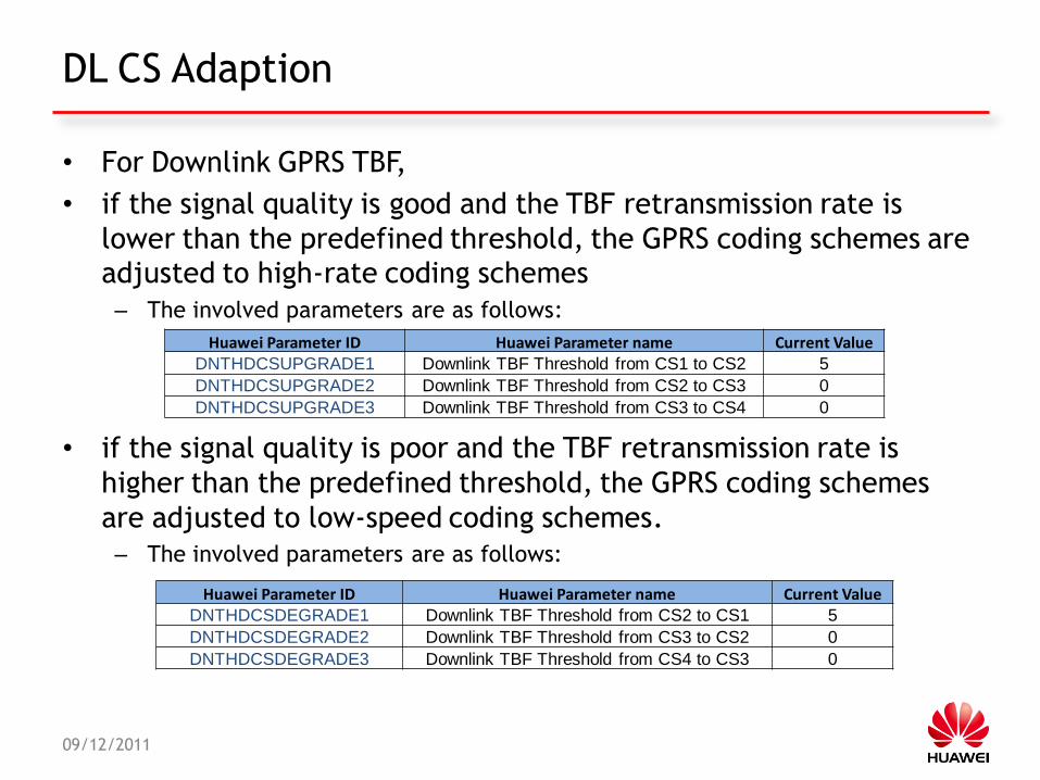
• For Downlink GPRS TBF,
• if the signal quality is good and the TBF retransmission rate is
lower than the predefined threshold, the GPRS coding schemes are adjusted to high-rate coding schemes
– The involved parameters are as follows:
• if the signal quality is poor and the TBF retransmission rate is
higher than the predefined threshold, the GPRS coding schemes
are adjusted to low-speed coding schemes.
– The involved parameters are as follows:
09/12/2011
DL CS Adaption
Huawei Parameter ID Huawei Parameter name Current Value DNTHDCSUPGRADE1 Downlink TBF Threshold from CS1 to CS2 5
DNTHDCSUPGRADE2 Downlink TBF Threshold from CS2 to CS3 0
DNTHDCSUPGRADE3 Downlink TBF Threshold from CS3 to CS4 0
Huawei Parameter ID Huawei Parameter name Current Value DNTHDCSDEGRADE1 Downlink TBF Threshold from CS2 to CS1 5
DNTHDCSDEGRADE2 Downlink TBF Threshold from CS3 to CS2 0
DNTHDCSDEGRADE3 Downlink TBF Threshold from CS4 to CS3 0

09/12/2011
DL CS Adaption
CS2
CS1 or CS2 DNTHDCSUPGRADE1 =5%
DNTHDCSDEGRADE1 =10%
Downlink Retransmission Rate
CS1
www.huawei.com
Copyright © 2011 Huawei Technologies Co., Ltd. All rights reserved.
MCS Adaptation

• EGPRS adopts a set of high-efficiency link quality control algorithms.
• It defines two link quality control modes: link adaptation (LA) and
incremental redundancy (IR).
• The link quality control mode is set by the parameter LQCMODE – LQCMODE= IR
• In LA mode, the sender selects the best modulation and coding
schemes based on the actual radio environment, and the receiver
need not buffer the erroneous data blocks received.
• In IR mode, the sender uses a coding scheme with high rates but weak
data protection for initial data transmission. If the data is received
erroneously, the sender retransmits the data by using a different
puncturing scheme.
– The receiver combines the new data with the previously received data and then
performs decoding.
– This process is repeated until the decoding succeeds.
09/12/2011
MCS Adaption

• For UL EGPRS TBF:
• The BSC determines whether to use the fixed MCS coding
scheme in the uplink based on the setting of UPFIXMCS.
– UPFIXMCS= UNFIXED
• The uplink initial coding scheme is specified by
UPDEFAULTMCS
– UPDEFAULTMCS = MCS5
• The BSC adjusts the uplink coding scheme according to the
uplink BEP measurement report sent from the BTS
– ADJUSTULMCSTYPE (Support EGPRS Uplink MCS Dynamic Adjust) = 2
09/12/2011
UL MCS Adaption

• The BSC adjusts the UL coding scheme according to the UL BEP
• BTS sends the BEP measurement report to the BSC through an
uplink data frame.
• BSC filters the BLER and BEP measurement reports
• After filtering the measured BEP values of the radio blocks, the
BSC obtains the MEAN_BEP and CV_BEP values on each timeslot.
• Then, the BSC sums up the MEAN_BEP and CV_BEP values on the
timeslots occupied by the TBF to obtain the MEAN_BEP and CV_BEP
values of the TBF.
• Based on the MEAN_BEP and CV_BEP values of the UL TBF, the BSC
chooses the required coding scheme against the UL BEP to coding
scheme mapping table.
09/12/2011
UL MCS Adaption

• To enhance the stability of coding scheme adjustment the leaky
bucket algorithm is used when the coding scheme in GMSK is
changed to the one in 8PSK.
• The basic principles of the leaky bucket algorithm are as follows:
– Each time the BSC adjusts the coding scheme in GMSK to the one in 8PSK, the
bucket size increases;
– each time the BSC adjusts the coding schemes within GMSK, the bucket size
decreases.
– The adjustment from GMSK to 8PSK is allowed only when the bucket size
reaches a specific value.
09/12/2011
UL MCS Adaption

CV_BEP
0 1 2 3 4 5 6 7
ME
AN
_B
EP
0 5 5 5 5 1 1 1 1
1 5 5 5 5 1 1 2 2
2 5 5 5 5 1 2 2 2
3 5 5 5 5 2 2 3 3
4 5 5 5 5 2 2 3 3
5 5 5 5 5 5 3 3 3
6 5 5 6 5 5 3 3 3
7 5 5 6 5 5 5 3 3
8 5 5 6 5 5 3 3 4
9 7 6 6 6 5 5 5 4
10 7 6 6 6 5 5 5 5
11 7 6 6 6 6 5 5 5
12 7 6 6 6 6 6 5 5
13 7 6 6 6 6 6 5 5
14 7 6 6 6 6 6 5 6
15 7 7 6 6 6 6 6 6
16 7 7 7 7 6 6 6 6
17 7 7 7 7 7 7 7 6
18 7 7 7 7 7 7 7 7
19 7 7 7 7 7 7 7 7
20 7 7 8 7 7 7 7 7
21 7 8 8 8 8 7 7 7
22 8 8 8 8 8 8 8 8
23 8 8 8 8 8 8 8 8
24 8 8 8 8 8 8 8 8
25 8 8 8 8 8 8 8 8
26 8 8 8 8 9 9 9 9
27 8 8 8 9 9 9 9 9
28 9 9 8 9 9 9 9 9
29 9 9 8 9 9 9 9 9
30 9 9 8 9 9 9 9 9
31 9 9 9 9 9 9 9 9
09/12/2011
UL MCS Adaption
• Example of Link Adaptation Table

• For DL EGPRS TBF:
• The BSC determines whether to use the fixed MCS coding
scheme in the DL based on the setting of DNFIXMCS.
– DNFIXMCS = UNFIXED
• The DL initial coding scheme is specified by DNDEFAULTMCS
– DNDEFAULTMCS = UNFIXED
09/12/2011
DL MCS Adaption
• The MS measures the DL quality periodically and filters
the measured values to generate a DL EGPRS channel
quality report.
• The DL EGPRS channel quality report is carried by the
EPDAN message sent from the MS to the BSC.
• The filtering period of downlink quality measured
values is specified by BEPPERIOD =5.
• The MEAN_BEP and CV_BEP values of the TBF are used
for the DL Link adaptation
• Based on the value of the MS OUT OF MEMORY field in
the EPDAN message, the DL MCS can be adjusted in the
following ways: next slide
09/12/2011
DL MCS Adaption

• If the value of the MS OUT OF MEMORY field is 0, – the MS has sufficient memory to perform the IR function
– The BSC adjusts the MEAN_BEP value of the TBF based on the BLER.
– Then, based on the MEAN_BEP and CV_BEP values of the TBF, the BSC chooses the required MCS in mapping table in IR mode.
• If the value of the MS OUT OF MEMORY field is 1, – the MS has no sufficient memory to perform the IR function.
– Then, based on the MEAN_BEP and CV_BEP values of the TBF
– The BSC chooses the required MCS in mapping table in LA mode
– To prevent ping-pong between MCS, the leaky bucket algorithm is triggered when the coding scheme is changed from GMSK to 8PSK.
09/12/2011
DL MCS Adaption

09/12/2011
CS/MCS Usage within LLV
0%
10%
20%
30%
40%
50%
60%
70%
80%
90%
100%
CS/MCS Usage within LLV Cluster
CS1 Codec Scheme Radio CS2 Codec Scheme Radio CS3 Codec Scheme Radio CS4 Codec Scheme Radio MCS1 Codec Scheme Radio
MCS2 Codec Scheme Radio MCS3 Codec Scheme Radio MCS4 Codec Scheme Radio MCS5 Codec Scheme Radio MCS6 Codec Scheme Radio
MCS7 Codec Scheme Radio MCS8 Codec Scheme Radio MCS9 Codec Scheme Radio

• MCS9 is used at 35% of time, this can be improved
• This linked to the high usage of MCS2 (up to 80%) on the cells
below, this high usage is due to Transmission problem (Abis) and/or
Lack of Abis resources
• Impacted Cells:
09/12/2011
CS/MCS Usage within LLV
0 10 20 30 40 50 60 70 80 90
100
MCS2 Codec Scheme Radio
MCS2 Codec Scheme Radio

www.huawei.com
Copyright © 2011 Huawei Technologies Co., Ltd. All rights reserved.
END