Embed Size (px)
Citation preview

THE BELGIAN PIONEER IN GAS DETECTION
DAT 420 Gas or oxygen detector
INSTRUCTION MANUAL

Copyright © 2016 by DALEMANS s.a.
Revision V1R7 • 07/2016
Any reproduction, whether partial or entire, made of this docu-ment, by whatever means, without the prior, written consent of DALEMANS s.a. is strictly forbidden.
All of the information contained in this document is non-contractual and is subject to modification without warning.
DALEMANS s.a. Rue Jules Mélotte, 27 • B-4350 Remicourt (Belgium) Phone +32 (0)19 54 52 36 • Fax +32 (0)19 54 55 34 Email: [email protected]
www.dalemans.com DAT 420 | 3
TABLE OF CONTENTS
WARNINGS .................................................................................................................. 4
LIMITATIONS ............................................................................................................... 4
DIRECTIVE 2014/34/EU (ATEX) .................................................................................. 5
DISCLAIMER ................................................................................................................ 6
ENVIRONMENTAL COMPLIANCE .............................................................................. 6
QUALITY ASSURANCE ............................................................................................... 6
1. INTRODUCTION ................................................................................................... 7
1.1. Certification ................................................................................................. 7
2. DESCRIPTION ...................................................................................................... 8
2.1. Overview ..................................................................................................... 8
2.2. Sensing head .............................................................................................. 9 2.3. Dimensions ................................................................................................ 10
3. INSTALLATION .................................................................................................. 11
3.1. Location ..................................................................................................... 11
3.2. Mounting .................................................................................................... 12
3.3. Field wiring ................................................................................................ 13 3.4. Connection to a DALEMANS control unit ................................................. 14
3.5. Connection to a Programmable Logic Controller (PLC)............................ 15
4. MAINTENANCE .................................................................................................. 17
4.1. Calibration ................................................................................................. 17
4.2. Sintered metal filter replacement .............................................................. 17
4.3. Sensing head replacement ....................................................................... 17 4.4. Troubleshooting......................................................................................... 18
4.5. Spare parts and accessories ..................................................................... 18
5. SPECIFICATIONS .............................................................................................. 19
www.dalemans.com DAT 420 | 4
WARNINGS
PRIOR to carrying out installation, maintenance, or service operations on the gas detector ensure that no gas or vapour is present in the surrounding atmos-phere.
INSTALLATION, COMMISSIONING and MAINTENANCE must be carried out by DALEMANS or by an approved service centre only, and in any case by qualified personnel who has received a suitable training.
Gas detection equipment must be calibrated at least once a year to mitigate the loss of sensitivity of the sensor.
The warranty provided by DALEMANS will be voided if this equipment is not installed, oper-ated and maintained in strict accordance with these instructions, warnings and within the op-erational limits stated.
By respecting these instructions you ensure the proper operation of the equipment. Should you require any further information about the installation, the use or the maintenance of this equipment, do not hesitate to contact DALEMANS.
Always follow the recommendations hereafter so as to avoid premature ageing of the sensor and to guarantee its optimal operation. These recommendations are general directives.
Refer to local regulations in force before proceeding with installation works (i.e. standards IEC 60079-14 and IEC 60079-29-2). Local regulations have always precedence on the rec-ommendations of the manufacturer.
Maintenance must be performed according to the procedure given by DALEMANS or his local representative. Maintenance or service attempts without observing these instructions or with-out the assistance of DALEMANS may prevent the equipment from working properly and from ensuring the safety of the occupants of the monitored premises.
Modification, disassembling and total or partial destruction of this equipment may invalidate the essential safety requirements of the whole plant.
Use only DALEMANS original replacement parts. The use of non-original parts may invalidate the certification and warranty of the equipment.
LIMITATIONS
Persistent exposure to high levels of toxic gas will shorten the sensor life. Sensors may be cross sensitive to other gases.
Long-term unpowered storage might shorten the electrochemical sensor life. Avoid discon-necting the electrochemical sensor from the amplifier Printed Circuit Board.
Gas detectors should be installed as late as possible in any program of construction opera-tions (i.e. construction of a new plant, refitting or maintenance) but before the presence of gas or vapours in the system, so as to avoid damage to sensors resulting in particular from such activities as welding and painting. If already installed, detectors should be protected by an air-tight seal to avoid contamination during construction works, and should be clearly marked as being non-operational.
Gas detectors must be protected from direct sunlight, vibrations and mechanical impacts.
www.dalemans.com DAT 420 | 5
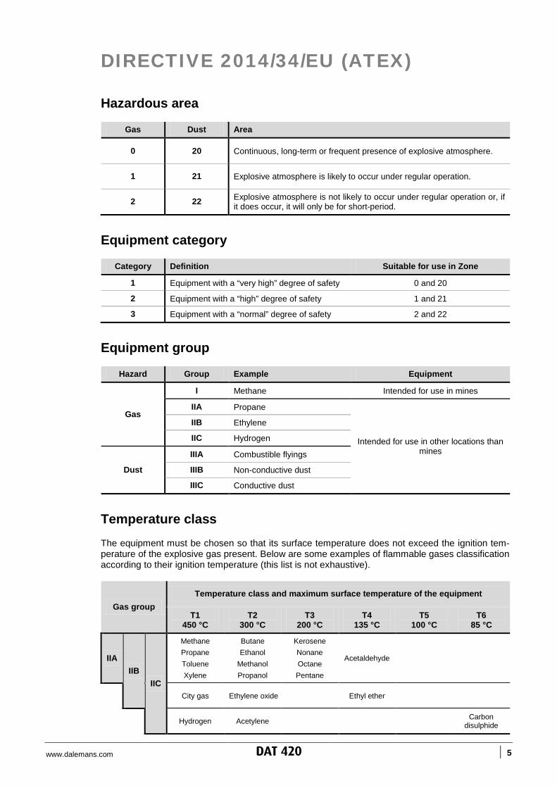
DIRECTIVE 2014/34/EU (ATEX)
Hazardous area
Gas Dust Area
0 20 Continuous, long-term or frequent presence of explosive atmosphere.
1 21 Explosive atmosphere is likely to occur under regular operation.
2 22 Explosive atmosphere is not likely to occur under regular operation or, if it does occur, it will only be for short-period.
Equipment category
Category Definition Suitable for use in Zone
1 Equipment with a “very high” degree of safety 0 and 20
2 Equipment with a “high” degree of safety 1 and 21
3 Equipment with a “normal” degree of safety 2 and 22
Equipment group
Hazard Group Example Equipment
Gas
I Methane Intended for use in mines
IIA Propane
Intended for use in other locations than mines
IIB Ethylene
IIC Hydrogen
Dust
IIIA Combustible flyings
IIIB Non-conductive dust
IIIC Conductive dust
Temperature class The equipment must be chosen so that its surface temperature does not exceed the ignition tem-perature of the explosive gas present. Below are some examples of flammable gases classification according to their ignition temperature (this list is not exhaustive).
Gas group Temperature class and maximum surface temperature of the equipment
T1 450 °C
T2 300 °C
T3 200 °C
T4 135 °C
T5 100 °C
T6 85 °C
IIA IIB
IIC
Methane Propane Toluene Xylene
Butane Ethanol
Methanol Propanol
Kerosene Nonane Octane Pentane
Acetaldehyde
City gas Ethylene oxide Ethyl ether
Hydrogen Acetylene Carbon disulphide
www.dalemans.com DAT 420 | 6
DISCLAIMER
DALEMANS cannot be liable for direct or indirect damages arising out of the non-observance of its instructions. Every effort has been made to ensure the accuracy of the information given in this document. Nevertheless, DALEMANS decline any responsibility in the event of errors or omissions in this document.
ENVIRONMENTAL COMPLIANCE
Waste Electrical & Electronic Equipment (WEEE Directive)
This symbol on the product and/or accompanying documents means that you are held to respect the regulation in force on the collection and recycling of Waste Electrical and Electronic Equipment (WEEE).
These provisions are intended to preserve the natural resources used for manufacturing this product and to avoid the dispersion of substances poten-tially harmful for the environment and human health.
Therefore, to dispose of your end-of-life product, you MUST hand it over to a designated collection point for the recycling of electrical and electronic equipment. For further information about the collection points in your area contact your local city authority.
QUALITY ASSURANCE
This product has been designed, manufactured and controlled within the framework of an ISO 9001 certified Quality Assurance system which has been assessed by a Notified Body according to Annex IV and VII of the Direc-tive 2014/34/EU (ATEX).
www.dalemans.com DAT 420 INTRODUCTION | 7
1. INTRODUCTION
The DAT 420 gas detector is intended for monitoring industrial and commercial confined areas. DAT 420 is suitable for use in hazardous areas of explosive atmospheres. It operates in associa-tion with a compatible control unit or with a Programmable Logic Controller (PLC) to provide early warnings of gas hazard or oxygen deficiency. For further information about the detectable gases or the list of compatible control units, please contact DALEMANS.
1.1. Certification
DALEMANS declares that the DAT 420 gas detector complies with the acceptable variations origi-nating from the type that has received the EC-Type Examination Certificate number FTZU 09 ATEX 0074. The measuring function, as defined under Annex II clause 1.5.5. of the ATEX directive 2014/34/EU, is not matter of this certificate. The said equipment is suitable for use in explosive atmospheres of hazardous areas, zone 1 and 2. Moreover, this equipment fulfils the provisions of the following directives and standards:
Directive 2014/34/EU (ATEX) EN 60079-0:2012 standard * EN 60079-1:2007 standard EN 60079-31:2009 standard
* The standard EN 60079-0:2009 which is mentioned on the EC-Type Examination Certificate was superseded by the new edition EN 60079-0:2012. A comparative analy-sis has shown that the substantial changes brought by the new edition are not relevant for this product.
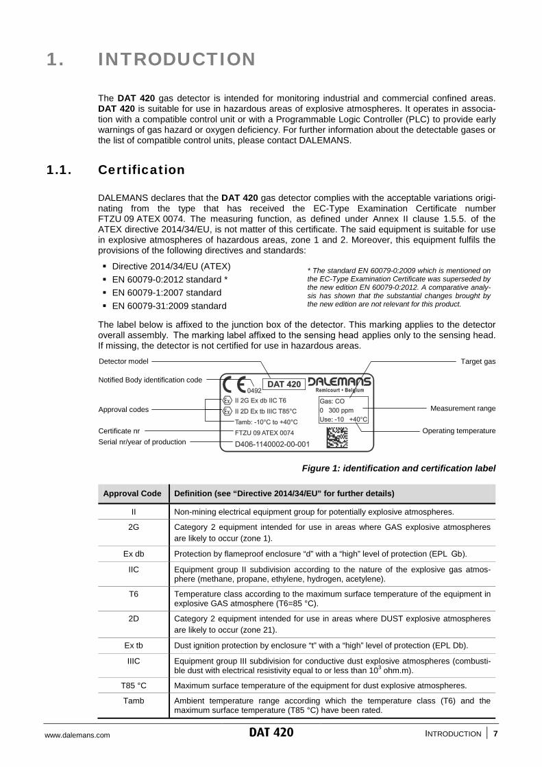
The label below is affixed to the junction box of the detector. This marking applies to the detector overall assembly. The marking label affixed to the sensing head applies only to the sensing head. If missing, the detector is not certified for use in hazardous areas.
Figure 1: identification and certification label
Approval Code Definition (see “Directive 2014/34/EU” for further details)
II Non-mining electrical equipment group for potentially explosive atmospheres.
2G Category 2 equipment intended for use in areas where GAS explosive atmospheres are likely to occur (zone 1).
Ex db Protection by flameproof enclosure “d” with a “high” level of protection (EPL Gb).
IIC Equipment group II subdivision according to the nature of the explosive gas atmos-phere (methane, propane, ethylene, hydrogen, acetylene).
T6 Temperature class according to the maximum surface temperature of the equipment in explosive GAS atmosphere (T6=85 °C).
2D Category 2 equipment intended for use in areas where DUST explosive atmospheres are likely to occur (zone 21).
Ex tb Dust ignition protection by enclosure “t” with a “high” level of protection (EPL Db).
IIIC Equipment group III subdivision for conductive dust explosive atmospheres (combusti-ble dust with electrical resistivity equal to or less than 103 ohm.m).
T85 °C Maximum surface temperature of the equipment for dust explosive atmospheres.
Tamb Ambient temperature range according which the temperature class (T6) and the maximum surface temperature (T85 °C) have been rated.
Detector model
Operating temperature d' ili i
Measurement range
Target gas
Notified Body identification code
Certificate nr
Approval codes
Serial nr/year of production

www.dalemans.com DAT 420 DESCRIPTION | 8
2. DESCRIPTION
2.1. Overview
The DAT 420 is a gas detector designed to detect the presence of toxic gases or oxygen defi-ciency in ambient air. It operates using an electrochemical sensor whose measure is converted by the transmitter into a 4-20 mA electrical signal which varies according to the gas/oxygen concen-tration. This signal is delivered to the control unit or to the Programmable Logic Controller (PLC) through a 2-wire current loop.
The DAT 420 is suitable for:
Use in hazardous areas other than mines (ATEX group II - equipment category 2); Use in zone 1 and 2 (gas) and 21 and 22 (dust) hazardous areas of explosive atmospheres; Operating at temperature from -10 °C to +40 °C for T6 temperature class.
The DAT 420 comprises the following main parts:
The flameproof “d” metal sensing head. The flameproof “d” metal junction box. The flameproof “d” metal cable gland. The 2-position terminal block for electrical connection.
The overall assembly has a flameproof “d” type of protection and an IP6X ingress protection.
Figure 2: DAT 420 detector overview
Terminal block
Flameproof sensing head
Flameproof junction box
Mounting bracket
Flameproof cable gland
Ferrite
www.dalemans.com DAT 420 DESCRIPTION | 9
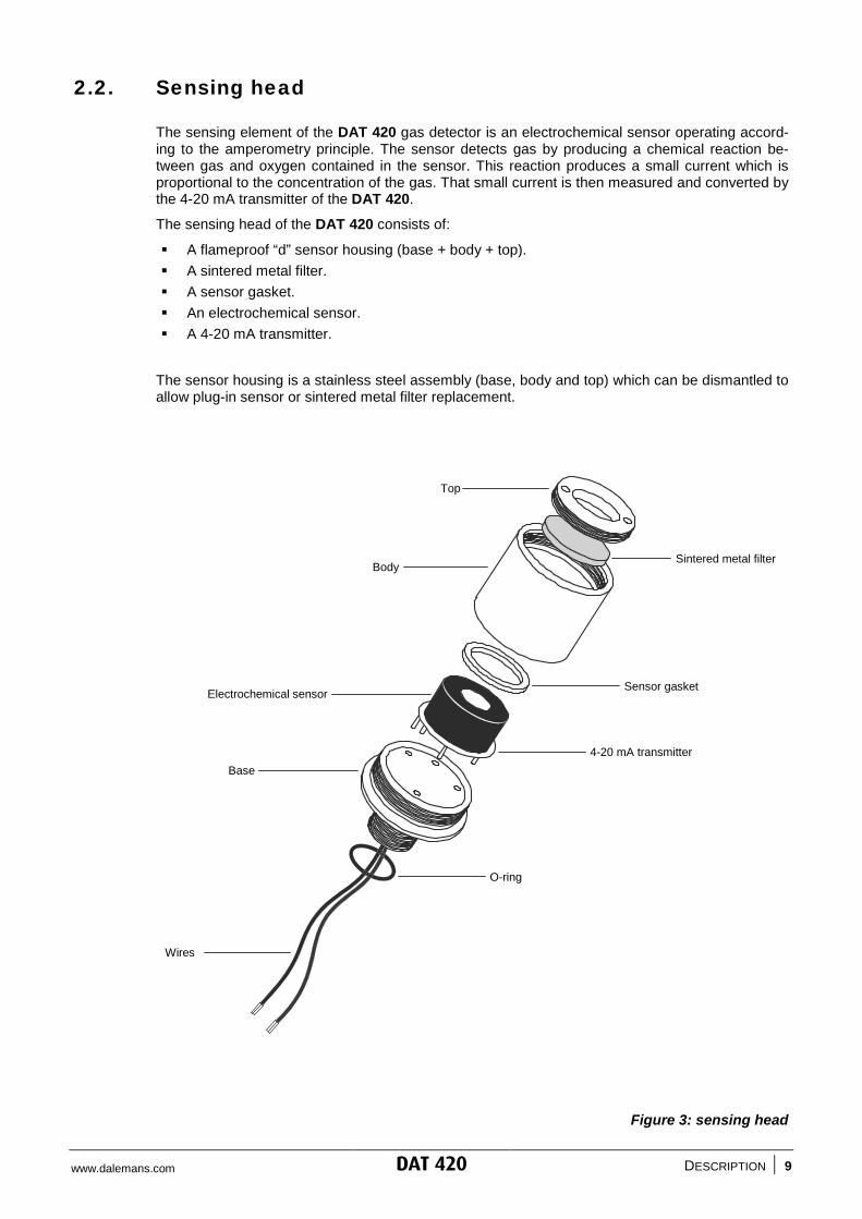
2.2. Sensing head
The sensing element of the DAT 420 gas detector is an electrochemical sensor operating accord-ing to the amperometry principle. The sensor detects gas by producing a chemical reaction be-tween gas and oxygen contained in the sensor. This reaction produces a small current which is proportional to the concentration of the gas. That small current is then measured and converted by the 4-20 mA transmitter of the DAT 420.
The sensing head of the DAT 420 consists of:
A flameproof “d” sensor housing (base + body + top). A sintered metal filter. A sensor gasket. An electrochemical sensor. A 4-20 mA transmitter.
The sensor housing is a stainless steel assembly (base, body and top) which can be dismantled to allow plug-in sensor or sintered metal filter replacement.
Figure 3: sensing head
Top
Sintered metal filter
Sensor gasket
Body
Electrochemical sensor
Base 4-20 mA transmitter
O-ring
Wires
www.dalemans.com DAT 420 DESCRIPTION | 10
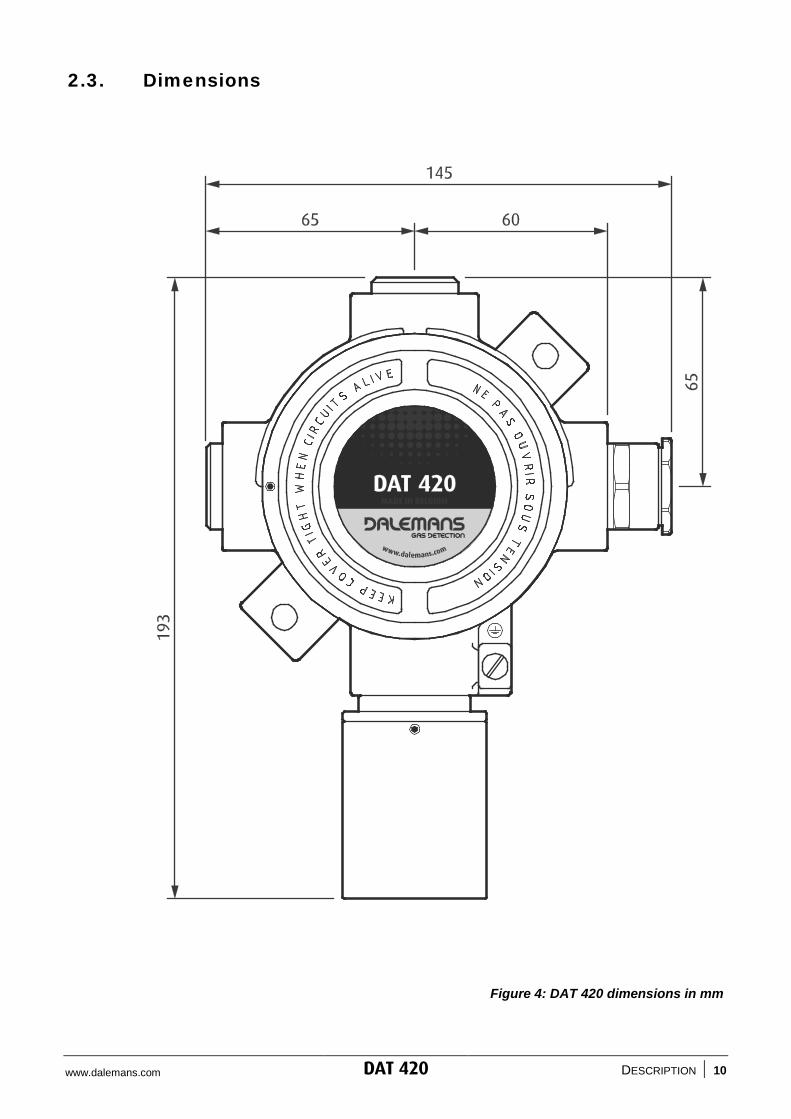
2.3. Dimensions
Figure 4: DAT 420 dimensions in mm

www.dalemans.com DAT 420 INSTALLATION | 11
3. INSTALLATION
3.1. Location
Gas detectors must be placed so that potential gas accumulations are detected before they create a significant hazard. Inappropriate location of a detector can nullify the effect and the integrity of the gas detection system.
The placement of the detectors should be determined in consultation with experts having specialist knowledge of gas dispersion, with those who have knowledge of process plant system and equip-ment involved, and with safety and engineering personnel. The location of every detector must be recorded and available to the safety personnel. Should you require any further guidance or assis-tance please contact DALEMANS or his local representative.
Consider the following points when positioning a gas detector:
The detector should be readily accessible for maintenance and electrical safety inspection. It must be possible to fit all accessories or test equipment for maintenance and servicing. Hazard level and potential sources of gas leak must be taken into account. Consider the combination of sources of gas release with propagation effects. The detector should be protected against operational hazards of the plant. The detector should be protected against vibrations and mechanical impacts. The detector should never be positioned directly above or below a water point. For outdoor installation, a protection against rain and/or sun exposition shall be installed. The detector should not be mounted in air currents. Always observe the operational temperature range of the sensor (refer to “Specifications”). To detect a gas which is lighter than air, place the detector at a high level. To detect a gas which is heavier than air, place the detector at a low level. If the gas density is close to air density, place the detector at breast height or one at high level
and another one at low level. Please note that gas density increases when temperature decreases.
The following table gives examples of detector locations depending on the gas to detect:
Gas * Formula Density (air = 1) Position
Ammonia NH3 0.59 High
Carbone monoxide CO 0.97 Breast height
Oxygen O2 1.11
Chlorine Cl2 2.49
Low Hydrogen sulphide H2S 1.19
Sulphur dioxide SO2 2.26
* This list is not exhaustive
www.dalemans.com DAT 420 INSTALLATION | 12
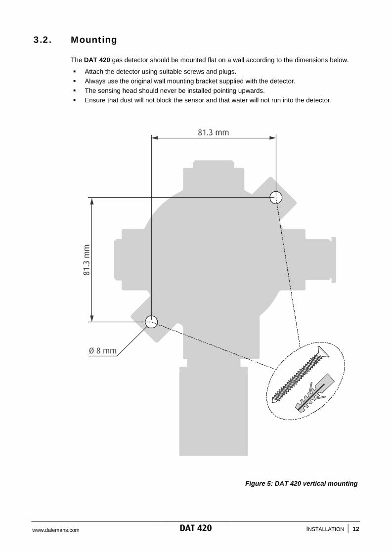
3.2. Mounting
The DAT 420 gas detector should be mounted flat on a wall according to the dimensions below.
Attach the detector using suitable screws and plugs. Always use the original wall mounting bracket supplied with the detector. The sensing head should never be installed pointing upwards. Ensure that dust will not block the sensor and that water will not run into the detector.
Figure 5: DAT 420 vertical mounting

www.dalemans.com DAT 420 INSTALLATION | 13
3.3. Field wiring
Always ensure that the electrical requirements of the DAT 420 gas detector meet the capability of the associated control unit or PLC (see “Specifications”).
Please follow the instructions below:
Field wiring must comply with local regulations and standards in force. DALEMANS recommend using colour coded cable with solid wires. Use a shielded or a screened twisted pair cable. The acceptable cross sectional area of the cable is 0.5 mm². The maximum cable length should not exceed 1000 m. The overall cable diameter must be within the range given below. The cable gland must be sufficiently tightened on the cable to ensure a good sealing.
Figure 6: DAT 420 wiring
www.dalemans.com DAT 420 INSTALLATION | 14
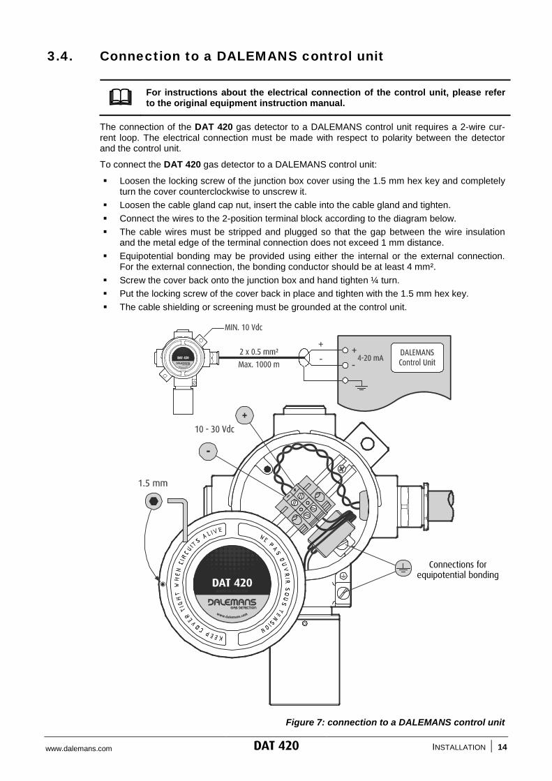
3.4. Connection to a DALEMANS control unit
For instructions about the electrical connection of the control unit, please refer to the original equipment instruction manual.
The connection of the DAT 420 gas detector to a DALEMANS control unit requires a 2-wire cur-rent loop. The electrical connection must be made with respect to polarity between the detector and the control unit.
To connect the DAT 420 gas detector to a DALEMANS control unit:
Loosen the locking screw of the junction box cover using the 1.5 mm hex key and completely turn the cover counterclockwise to unscrew it.
Loosen the cable gland cap nut, insert the cable into the cable gland and tighten. Connect the wires to the 2-position terminal block according to the diagram below. The cable wires must be stripped and plugged so that the gap between the wire insulation
and the metal edge of the terminal connection does not exceed 1 mm distance. Equipotential bonding may be provided using either the internal or the external connection.
For the external connection, the bonding conductor should be at least 4 mm². Screw the cover back onto the junction box and hand tighten ¼ turn. Put the locking screw of the cover back in place and tighten with the 1.5 mm hex key. The cable shielding or screening must be grounded at the control unit.
Figure 7: connection to a DALEMANS control unit
Connections for equipotential bonding

www.dalemans.com DAT 420 INSTALLATION | 15
3.5. Connection to a Programmable Logic Controller (PLC)
For instructions about the electrical connection of the PLC, please refer to the original equipment instruction manual.
Prior to connecting the DAT 420 to a PLC please follow these instructions:
Use an external stabilized power supply for the detector (+24 Vdc). Ensure that the polarity of the detector output signal matches the polarity of the PLC input. Please read the instructions below regarding the loop resistance.
Loop resistance
The supply voltage applied to the detector has direct influence on the MAXIMUM loop resistance. This resistance includes the cable resistance and the shunt resistor of the PLC.
Example
- The minimum operating voltage of the DAT 420 is 10 Vdc.
- Consider a supply voltage of 24 Vdc, the allowable voltage drop due to the loop resistance is 14 Vdc.
- The MAXIMUM loop resistance will be:
0070.0214
I10-24R
LoopLoop === ohms
- With 20ILoop = mA
- For a 1 to 5 Vdc input scale, the shunt resistor to put across the PLC input will be:
2500.02
5I
5RLoop
Shunt === ohms
- Therefore, the maximum allowable resistance for the cable will be:
450250700RCable =−= ohms
Figure 8: supply voltage vs RLoop

www.dalemans.com DAT 420 INSTALLATION | 16
Connection to a PLC
To connect the DAT 420 gas detector to a PLC:
Loosen the locking screw of the junction box cover using the 1.5 mm hex key and completely turn the cover counterclockwise to unscrew it.
Loosen the cable gland cap nut, insert the cable into the cable gland and tighten. Connect the wires to the 2-position terminal block according to the diagram below. The cable wires must be stripped and plugged so that the gap between the wire insulation
and the metal edge of the terminal connection does not exceed 1 mm distance. Equipotential bonding may be provided using either the internal or the external connection.
For the external connection, the bonding conductor should be at least 4 mm². Screw the cover back onto the junction box and hand tighten ¼ turn. Put the locking screw of the cover back in place and tighten with the 1.5 mm hex key. The cable shielding or screening must be grounded at the PLC. Connect a shunt resistor across the PLC input. Choose the resistor value according to the
PLC input scale (see above). The resistor must have a power rating of at least 1 Watt.
Figure 9: connection to a PLC
Connections for equipotential bonding
RShunt (min. 1 W)
Stabilised power supply
www.dalemans.com DAT 420 MAINTENANCE | 17
4. MAINTENANCE
Prior to carrying out maintenance or service operations on the gas detector, inhibit the safety function of the detector on the associated control unit or PLC and secure any output device connected to the system to prevent false alarms and unintended actuations. Never open the detector when flammable gas is present. Regularly remove dust from the detector WITH A DAMP CLOTH ONLY to avoid the risk of electrostatic sparks.
4.1. Calibration
Gas detectors must be calibrated at least once a year to mitigate the possible loss of sensitivity of the sensor. This calibration must be performed according to the procedure given by DALEMANS or his local representative, and in any case by qualified personnel who will have received a suit-able training.
4.2. Sintered metal filter replacement
If contamination of the sintered metal filter by solvent, gas or vapour has occurred, the sensing head must be replaced and the inspection frequency should be increased twofold.
Unscrew the sensing head top using the suitable tool OUT00000113.
Replace the sinter metal filter with a new one MEC00000010.
Screw the sensing head top back on again and tighten.
Make sure the sensing head is still correctly fastened to the junction box.
Perform calibration according to the procedure given by DALEMANS or his representative.
4.3. Sensing head replacement
Loosen the locking screw of the junction box cover using the 1.5 mm hex key.
Completely turn the cover counterclockwise to unscrew it.
On the terminal block, disconnect the two wires of the sensing head and remove the ferrite. Unscrew the sensing head using the tool OUT00000114 placed between the base and the
junction box.
Screw the new sensing head back on again and tighten.
Put the ferrite on the wires and reconnect them to the terminal block (see Figure 2):
RED wire on terminal +
BLUE wire on terminal -
Screw the cover back onto the junction box and hand tighten ¼ turn.
Put the locking screw of the cover back in place and tighten with the 1.5 mm hex key.
Power on the detector and restore its safety function on the control unit or the PLC.
Perform calibration according to the procedure given by DALEMANS or his representative.

www.dalemans.com DAT 420 MAINTENANCE | 18
4.4. Troubleshooting
Problem Possible cause(s)
Non-zero reading Possible presence of gas in the detector area.
Non-zero reading when no gas is present Detector needs calibration.
Reading too high or too low
Zero reading in presence of gas Wrong or defective electrical connection.
Sintered or sensor blocked with dust.
Sintered or sensor contaminated. Replace sin-tered AND sensor.
4.5. Spare parts and accessories
Part or accessory Part number
Cable gland - Ex “d” M20 (6.1 - 11.7 mm) PRE00000032
Cable gland - Ex “d” M20 (6.5 - 14 mm) PRE00000036
Ferrite FER00000001
Junction box - Ex “d” BOI00000188
Key for locking screw (1.5 mm hex key) OUT00000115
O-ring 17 x 2 mm MEC00000012
Screw - Locking screw of the junction box cover VISVIS00067
Screw - M4 x 6 mm VISVIS00042
Screw for locking the body of sensing head VISVIS00066
Sensing head - FPH01 *
Sensor gasket MEC00000018
Sintered metal filter MEC00000010
Spanner for base of sensing head (30 mm) OUT00000114
Spanner for top of sensing head OUT00000113
Stopper plug - Ex d M20 PRE00000033
Terminal block - Ex “e” 2 position BOR00000087
Transmitter board - 4-20 mA BASTRX00017
* Depends on the type of sensor used

www.dalemans.com DAT 420 SPECIFICATIONS | 19
5. SPECIFICATIONS
MODEL DAT 420
Sensing head 1.4404 stainless steel (AISI 316L)
Sintered metal filter
Junction box Aluminium
Dimensions 193 x 145 x 90 mm
Weight 1500 g
Output signal 2-wire 4-20 mA current loop
Settings Zero and calibration by internal potentiometers
Response time (T90) < 45 s
Operating voltage 10 - 30 Vdc
Current consumption Max. 30 mA
Measurement principle Electrochemical sensor
Measurement range Other gases / ranges upon request
Ammonia (NH3) 100, 1000, 5000 ppm
Carbone monoxide (CO) 300, 500, 1000 ppm
Chlorine (Cl2) 10, 50 ppm
Hydrogen sulphide (H2S) 50 ppm
Nitrogen dioxide (NO2) 20, 50 ppm
Oxygen (O2) 25 %
Sulphur dioxide (SO2) 20 ppm
Operating temperature -10 °C to +40 °C
Storage temperature -40 °C to +80 °C
Ambient humidity 20 - 90 % HR
Intermittent humidity 10 - 99 % HR
Pressure 90 - 110 kPa
Accuracy ± 1.5 % measurement range
Expected operating life > 2 years
Wiring 2 x 0.5 mm² twisted and shielded pair
Maximum cable length max. 1000 m
Loop resistance 50 - 750 ohms
Cable entry 1 x M20 / 6.1 - 11,7 mm (other size upon request)
Ingress protection IP6X (dust tight)
Approval (ATEX) GAS DUST
Hazardous area Zone 1 or 2 Zone 21 or 22
Equipment group IIC IIIC
Marking II 2G Ex db IIC T6 II 2D Ex tb IIIC T85 °C
Tamb = -10 °C to +40 °C for T6 and T85 °C
Standards EN 60079-0:20120 EN 60079-1:20070 EN 60079-31:2009
Certificate number FTZU 09 ATEX 0074

www.dalemans.com THE BELGIAN PIONEER IN GAS DETECTION
Rue Jules Mélotte 27 • B-4350 Remicourt Tel. +32 (0)19 54 52 36 Fax +32 (0)19 54 55 34 [email protected]
OFFICIAL DEALER