Embed Size (px)
Citation preview
8/8/2019 Data 20 Communication 20Basic 20 Concepts
http://slidepdf.com/reader/full/data-20-communication-20basic-20-concepts 1/16
“Datapro Communications Analyst”Data Communications: Basic
Concepts
1001 DNW
Data Communications:
Basic Concepts
Datapro Summary
Data communications is an integral part of business. Whether a data network accommodates 10 personal
computers on a LAN or 100 nodes in a global network, data comm unications is the link for greater productivity,
efficiency. and cost savings. This report offers an overview of data comm unications principles, the products and
services comprising a data network, and the issues facing this dynamic industry.
43~ Thomas No//e
Pwsid& C/MI Corp.
Lipdated by Datapro staff.
Basic Principles of Data CommunicationsData comm unications is the set of products. concepts, and services that enable the connection of compu ting
systems. In this context, a “ computing system” can be a source of information or information processing or a
medium allowing an information user to access such a source. The “connection” ma’t’ be one that explicitlv
make s one system the “ client” and the other the “server,” as is the case with terminai-to-computer relationships.
It may also be “peer” in nature, imposing no specific master/slave relationship. A collection of such connections,
supported over a common circuit structure an d using shared technological compon ents. is called a data network.
The elements of data comm unications are all slaves to the relationship between the business applications for
compu ting, the carrier service an d standards infrastructure (which includes regulatory issues), and the
technology available. In the past. these factors tended to make data comm unications and data networks slaves of
data processing planning. While it is not yet true that networks drive applications more than computers, it is
certainly true that networks must be considered in designing huma n-system interactions. In the past, it was
possible to develop compu ting applications without anv form of data network. That is uncomm on today and willbe impossible in the near future.
Technical Basis of Data Communications
Comp uter systems and their associated devices store and use information using a binary coding. The numbe r of
binary bits that make up a character of information has varied, but the majority of systems today use eight binary
bits to a character, or “byte.” This allows 256 different combinations of value. which can be mapp ed to represent
letters, nu mbers, and special symbols. Any combination of bits can represent an ything, as long as the systems
using the data agree on the value. But to simplify information storage and retrieval, a standard code se t is
normallv employed. There are two such code sets in comm on use todav: the Extended Binary Coded Decima l
lntercha~~ge Code (EBCDIC), developed by IBM and used on its large*systems, and the American Standard
Code for Information Interchange (ASCII). a formal stand ard used by most midrange and personal computers.
Code sets describe OI I I V how textual or “ character” data is stored; there are other standards for the storage of
binary num eric data, both fixed point and floating point. A standard representation is necessary whenever
information generated by! one system must be read by another. This can occur if the systems exchange a
transportable media like magn etic tape. It can also occur if the systems are linked over a comm unications
channel. One computer system or device co uld com municate data to another over a wire or circuit if two basic
sets of conditions were true:
l The information channel was capable of transporting binary information with no errors or amb iguities
sufficient to interfere with the application.
0 1995 McGraw-H i l l , Incorporated Reproduct ion Proh ib i ted
Datapro In format ion Serv ices Group, De l ran NJ 08075 USA
May 1995
8/8/2019 Data 20 Communication 20Basic 20 Concepts
http://slidepdf.com/reader/full/data-20-communication-20basic-20-concepts 2/16
“Datapro Communications Analyst”Data Communications: Basic IOOlDNW
Concepts
l Both agreed on the strategy to be used to transfer the information and the structure of the information itself.
Data comm unications can be viewed a s the set of strategies needed to ensure these conditions.
Analog and Digital Channels
An easy wav to transmit binary da ta is to simply impress a two-value signal (+5 volts and -5 volts, +8 volts and
0 volts, etc.) on the channel, with one of the values used to represent the binary I and the other the binary 0. This
is called digital enc oding, and it requires a circuit capable of transmitting the kind of “square” pulses shown in
Figure “Anulog and Digital Coding Techniques.”The most pervasive comm unications system in the world is the voice telephone system, so it is logical to
assum e tha t any practical data comm unications network would have to rely heavily on this pervasive system for
support. Unfortunately, hum an voice is not binary data, and the voice phon e system was designed to pass audio,
or analog, data. In fact. it was designed to pass the relatively narrow range of frequencies in which hum an voice
carries most of its intelligence--roughly 300 Hz to 4000 Hz.
To make analog circuits suitable for digitally encoded information, it was necessary to develop a system to
modify or modulate an analog signal or carrier in such a way that changes generated in response to a binary I
could be distinguished from those generated in response to a binary 0. This might be done, for example, by
transmitting a tone of I kHz for a “1” and 2kHz for a “0.” A device at the other end could then, by separating the
tones, recover the digital signal. This modulation system, called frequency shifi keying, is still in use in
telegraphy and is illustrated in Figure “Analog and Digital Coding Techniques.” ?r c
A digital chan nel can. therefore, be created by a pair of modulator/dem odulator devices linked by an analog
channel. The devices became known by the acronym modern. Today’s modems employ enhanced techniques of
information coding. increasing reliability and information capacity. However, all modem s operate by impressing
multiple values onto an analog carrier sign al to represent digital d ata.
As the public telephone system advanced, the advantag es of integrated circuitry in processing phone signals
became clear. Digital signals can be regenerated more easily in the presence of noise, because they can only
have one of two possible values. Thus, the phone system moved to a strategy of digital coding of voice data
through pulse code modulation, or PCM .
Digital samp ling of voice information at a rate of 8,000 times per second, with 256 possible values per sample ,
requires 8,000 x 8 bits or 64K bps capacity. This type of digital channel. called a “ DSO,” is the foundation of
today’s digital carrier system or “ T-carrier” system. Tl, w hich consists of 24 DSO channels plus a framing bit, is
a I S44M bps channel often used in integrated voice/data networks.
Digital channels can be used to carry data directly; all that is needed is to connect the data device to the
channel in some way. In North A merica, this is done with a two-step device called a channel service unit/data
service unit (CSU /DSU ).
Protocols: Asynchronous and Synchronous
CSU/DS Us, in conjunction with digital channels or modems and analog channels. can transport binary data.
satisfying the first of the two requirements for data comm unications. The second requ irement is an agreement on
the format and rules for the exchange, called the “protocol.” The most b asic element of a protocol is the
definition of how data stored in a computer will be transferred to the line, and in what bit order. Another issue is
just ho w the receiving device will divide up the bytes into bits. This is more complex than it sounds; information
moving at a rate of 9600 bits per second (bps) would gene rate a new bit about once every 100 microseconds.
There are two major strategies for synchronizing the bit/character timing of comm unications: asynchronous andsynchronous. Figure “S~wchrmous and Asynchr*onozts Transmission Blocking Techniyltes” shows the difference
between the two.
Asynchronous comm unications places the bits on the line by framing them in a “start” and “stop” bit, with a
predictable value. Th is allows the receiver to distinguish the start of a character from a condition of an idle
channel. Within the character, the sender and receiver m ust “ clock,” or time the bit intervals accurately. This is
not a problem for a single eight-bit character. Because of the start and stop bits, however, the asynchronous
strategy requires an average of IO bits to be transmitted to send the S-bit character.
Synchronous comm unications is designed to eliminate this waste by grouping all of th e char acters of a
messag e into a block and sending them together, The block is started with a “sync character,” or “flog,” and ends
0 1995 McGraw-H i l l , Incorporated. Reproduct ion Proh ib i ted
Datapro Inform atIon Services Group , Delran NJ 08075 USA
May -t995
8/8/2019 Data 20 Communication 20Basic 20 Concepts
http://slidepdf.com/reader/full/data-20-communication-20basic-20-concepts 3/16
Communications Data Corn
Concepts
munications: Basic 1001 DNW 3
with an error-checking sequence designed to help the receiver detect block errors. Bu t because blocks are likely
to be long, the transmitter and receiver cannot track accurately and might lose count of where ch aracters begin
and end (“lose svnc”). To prevent this, synchronous channels provide both sender and receiver a standard clockdsignal.
Asynchronous comm unications is inefficient when used with devices that can coHect and configure
information into blocks, but it is still very comm on for simple connections where the characters sent on a line
are keyed by, or displayed to, a hum an operator. Synchronous data Iinks are best implem ented where direct
hum an intervention is not possible because of the speed. The ability of a hum an to view the result of aconnection mea ns that little must be done by the computer!terminaI to protect data; the “protocol” is that there is
no special procedure. Thus. the term “asynchronous protocol” mean s that characters are sent as they are keyed or
as they are to be displayed, with little or no control dialog.
Synchronous blocks. hav ing a potential strategy for block error detection and correction, can justify a more
complex set of rules for information exchange. “ Synchronous protocols” are therefore more complicated.
employing strategies for detecting and correcting errors, controlling the rate of flow, and setting other
characteristics of connections.
Protocols-The OSI Model
From the titne of the first practical data networks in the late 19 150s~ protocols” have been an area of concern,
Cotnm unications is not possible betw een two systems that disagree on the procedures--that have different
protocols. Com puter vendors all invented their own (IBM’s Binary Synchronous Com munica tions or Bisync was
an early, popular examp le). Because each was incompa tible, equipme nt from different vendors could not
communicate.
In the early 197O s, a group of international comm unications experts devised a model for the connection of
generalized data systems through communications networks. The tnodel was called the “ Open Systems
Interconnection Basic Reference Model” and became known as the OS1 model, the structure of which is shown
in Figure “ The CXI Model Networ~k.”
The model divides all of the functions of data comtnunica tions into seven layers. each of which provides a
cohesive set of services. International standard s for each of the layers were developed in succeeding years, and
even vendor-proprietary protocols took on the basic structure. The OS1 model is the basis for higher-level
protocols.
Communications Standards
The need for both parties in a connection to agree on data presentation and dialog controt rules, the protocol, has
already been noted. Stan dards to define these rules are as old as data commun ications and arise from three major
sources:
l Vendors thetnsetves whose proprietary protocols may be “ open” to support by other vendors because the
originating vendor publishes the specifications. IBM’s Systems Network Architecture (SNA ) is an example of a
proprietary, but “ open” protocol.
l Trade groups or consortiums, which represent sp ecial interests in a given comm unications market. The
Institute of Electrical and Electronic Engineers (IEEE) is a trade group that has protnoted the basic standard s for
local area networking, IEEE 802.
l National or international standard s bod ies, which formally debate rules and publish standard s. In the U.S., the
Am erican National Standa rds Institute (ANS I) and the National Institute for Standa rds and Technology (NIST,formerly the National Bureau of Standa rds) are the principal standard s bodies. The International Organization
for Standardiza tion (ISO) and the International TeIecotnm unications Union-Telecom munications
Standardiza tion Sector (KU-TSS. formerly known as the CCITT) are the two international standard s group s
most involved in data comtnun ications.
The OSI model is not itself a standard , but a framework wlhich describes the relationship of standard s. There are
standa rds for each of the seven OSI model layers, often several at the same layer.
Applications for Data Communications
0 1995 McGraw-HI11 , Incorporated Reproduct jon Proh i b i ted.
Datapro ln format ton Servtces Group, De l ran NJ 08075 USA
May 1995

8/8/2019 Data 20 Communication 20Basic 20 Concepts
http://slidepdf.com/reader/full/data-20-communication-20basic-20-concepts 4/16
“Datapro nications Analyst” Data Corn
Concepts
nications: Basic 100’lDNW
Data comm unications and data networks serve the information processing systems used, or contemplated, by a
business. All information technology planning is based on estabt ishing a user-to-source relationship and
identifying the technology elements needed to support it. Data networks are such an element, and data
cotnmun ications is the foundation of data networks.
Early data comm unications applications were developed when computer facilities were so expensive th at
access to a cotnputer had to be given to numerou s users via relatively primitive entry/display terminals. The
computer processed and fortnatted all information at its central location. But as technology advanced, it created
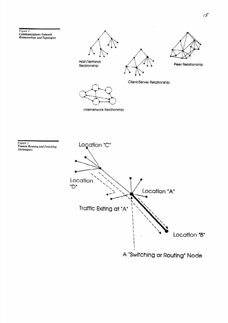
the microprocessor and enabled the development of inexpensive desktop compu ter system s. These allowedcotnputing power an d information storage to be dispersed. In this new environment, four distinct types of data
cotntnunications relationships developed: host/terminal, client/server, peer or distributed processing, and
internetworking. Figure “ C(~nlnlz(17icatior~s etwork Relationships and Topologies” shows an example of the way that
each type of relationship affects the structure of the network that must support it.
HoWTerminal Relationships
Norma llv, host/terminal applications occur when the process of information entry and display is the major
element bf the application, and the goal is to support the fastest rate of acquisition or output of data. In almost all
cases, the system interaction is to a huma n operator, either directly (via keyboard and display) or indirectly (via
printout).
In host/terminal applications, the speed of the human /mecha nical component of the connection is often low
enough to limit the information flow rate to a level well below that of channel capacity. Because of this,
host/terminal networks often include facilities to share the information channel among multiple terminals to
reduce overall cost. These de vices are called “terminal servers” or “ cluster controllers.” IBM’s popular 3270
family of devices includes the 3 174 cluster controller.
Wh en a desktop computer is used to “ emulate” a terminal, the interaction between the personal or other
desktop com puter and its partner system is still considered a host/terminal interaction. Any processing
capabilities of the desktop system are “hidden” by the fact that the PC is emula ting a dumb terminal.
Host/tertninaI applications are forgiving of channel limitations. Their relatively limited speed has already been
noted: high-capacity channels can be justified only by sharing them among multiple termin als. Host/terminal
applications are also generally imm une to delays in the data path, since the hum an reaction titne is normally tong
enough to hide any network transit delay.
Networks for support of host/tertninal relationships take on a “tree” structure, as shown in Figure
“ Comntrnicatiom Netwwk Relationships a nd Topologies. ” The tertninals are often concentrated via cluster controllers
or servers onto a shared trunk, which may be further c oncentrated to a higher-speed facility. All infortnation
paths lea d to the computer systetn at the heart of the structure, and there is no connection between users except
through that computer.
Client/Server Relationships
Client/server applications utilize a small computer at the point of huma n/system interaction and a larger one as a
central repository for infortnation and/or information processing power. The client system can provide local
services to its user, but it may from time to time require access to information stored a t the server or to the
server’s specialized processing resources. Wh en this happen s, the client reties on a data comm unications
connection to the server. The file sharing and printer sharing done in PC-bas ed local area networks (LANs) is a
common example of a pritnitive fortn of client/server computing.Because client/server applications are between computing systems and not between a system an d a huma n, the
speed of the exchange of infortnation is not limited to huma n rates. Thus, the applications utilize a much higher
channel capacity for the brief period of the interaction, though the capacity might be wasted during periods wh en
the client svstem wa s involved in a local user dialog only, Client/server applications, therefore, benefit from
strategies for sharing infortnation channels as well.
w
The extent to which the client and server systetns interact in satisfying a user need varies con siderable. Some
systems, such as electronic tnail systems, simply deliver a messa ge to a client to be read by its user at ati
convenient titne. In this case, the client/server interaction is relatively infrequent and not highly constrained by
performance. But if the client system is processing a remote da tabase, each record may be sent over the network.
0 1995 McGraw-H i l l , Incorporated. Reproduct ion Prohtb i ted.
Datapro ln format ron Serv ices Group, De l ran NJ 08075 USA
May 7995

8/8/2019 Data 20 Communication 20Basic 20 Concepts
http://slidepdf.com/reader/full/data-20-communication-20basic-20-concepts 5/16
“Datapro Communications Analyst”Data Communications: Basic
Concepts
1001 DNW
In the latter case, network performance will have a major imp act on the application. Client/server relationships
often place information sources farther out toward the network user? often at the points of concentration. To
provide a ccess to these resources without loa ding the host, intermediate cross-connections are often provided,
creating a meshin g of these concentration points.
Peer Relationships
A client/server application requires two smart system devices, for example, a desktop computer and a data
center system. However, despite the fact that both devices are computers, there is a master/slave relationshipinherent in the fact that the server is a source of information--often for many clients.
Peer applications have no such inherent master. Peer systems are those that have relatively little difference in
information storage or processing capacitv and are capable of adopting virtually any sort of relationship with
one another according to the mom entary ieeds of the application or user.
Peer connectivity is the most challenging of all types of connectivity to provide, since there is no preferred
information focus among the systems comm unicating. Without such a focus, any numbe r of connections and
flow volumes could b e possible, and the capacity and number of channels needed to support them make design
of a total network difficult. The unpredictability also make s it difficult to concentrate traffic for efficient use of
circuits; there are no consistent partners to create consistent patterns of flow. A peer network, therefore, tends to
connect users at all levels.
There are few/ true peer applications today, becau se most compa nies have central data center resources or other
departmen tal information storage points. Peer networking is most likely to be found in compa nies that rely on
personal com puters or desktop UNIX systems.
Internetworking Relationships
All of the relationships described so far have been between information systems an d have been explained in an
application context. The last relationship, internetworking, is not a system relationship at all. but a network
relationship affecting all users on the network.
Internetworking is most likely to occur when a business that has previouslv planned d ata comm unications on a
per-application basis begins to consider it as a kev part of its strategic planning. A large part of creating a
strategic network is mak ing information access M iithin the firm more universal, something that is often called
“building an enterprise network.” reflecting the breakdow n of internal network barriers.
In a technical sense, inter-networking is the task of building a single, large network by combining existing ones
while retaining the application support charac teristics of each of the networks. Figure “ Communications Net-work
Relationships and Topologies” shows an internetwork structure created by linking a series of LAN s. It is an area
supported by specialized products discussed in the Switching Devices section later in this report.
Data Transmission Services
Given an application, the goal of data communica tions is to identify a set of transmission services that can be
made to effectively support it and the equipmen t necessary to provide whatever adaptation is required.
There are four major options for data transmission available to users:
I. Public carrier services provide raw analog or digital transport capacity, often suitable for other forms of
information transfer as well. D ial-up and leased analog an d digital lines are examples of this.
2. Public value-added networks, also called “packet switched n etworks,” are designed to transport data only, andto do so at an attractive price relative to the more general analog and digital lines.
3. Private tran smission systems on a single prem ises, based on local copper w ire or other technology, are
supported by a central switching device, such as a PBX , They may be called “local data switched services.” If
thev are provided bv a shared high-capacity channel, thev are called LAN s.
4. Private tran smiss4ion systems can be based on radio or’optical technology, which can operate over distances of
50 miles or more, Private microwave is the most common example of this type of system.
A “private network” is a collection of transmission services design ed to provide user-to-user connectivity at a
lower cost than could be achieved through the use of public switched services. Most “private networks” stilt relv
on leased carrier services.
0 1995 McGraw-HtII incor porated. Reproduct ion Proh ib i ted
Datapro In format ion Serv ices Grou p, Delran NJ 08075 USA
May 1995

8/8/2019 Data 20 Communication 20Basic 20 Concepts
http://slidepdf.com/reader/full/data-20-communication-20basic-20-concepts 6/16
“Datapro Communications AnalysYData Communications: Basic
Concepts
1001 DNW
Local Area Networks (LANs)
In the late 1970~~ a Ph.D. candidate named Robert Metcalfe suggested that a coaxial cable might be routed
around a facility and tapped into by each user connection. The information capacity of such a cable. IO tnillion
bits per second, would be high enough to reduce loading and contention frotn this shared use to tolerable levels.
This was the first practical definition of a local area network and its subseque nt comm ercial exploitation by
Xerox, Intel. and Digital Equipme nt--Ethernet.
Ethernet was originally designed to support terminal acce ss, but the LAN quickly becam e associated withpersonal compu ters. A cotnmittee sponsored by the IEEE was charged with developing standa rds for LAN s, and
most LA Ns today ad here to the IEEE 802 standard set. LAN s can be classified according to their topology and
their access control. Topology refers to the physical configuration: access control to the way in which users are
granted access to the LAN to send data. The most popular topologies are the bus, the star, and the ring. The most
popular access control strategies are carrier sense multiple access with collision detection (CSM A/CD ) and
token passing. Ethernet is a CSM A/CD bus LAN; IBM’s Token-Ring is a token-passing ring.
Today, LAN s offer inexpensive and easy-to-implement comm unications between PCs, engineering
workstations. midrang e, and mainfram e compu ters, and allow the delivery of many shared applications and
services that were not possible before the advent of the LAN . Early LAN s allowed the sharing of printers and
disk drives; today’s systetns offer electronic mail, fax and imagin g services, access to pools of modem s and
comm unications gateway s, and the increasingly popular groupware,
Wide Area Bandwidth Services
Most data comtnunications today is based on carrier circuits designe d for use by data. voice, fax, and other
information forms because they supply only “band width” or unstructured information capacity. These circuits
can be classified according to their capacity, as follows:
l Voice grade circuits, analog lines with a data capacity of up to approximately 19.2K bps. Telephone dial lines
and leased analog lines are examp les of this type of service.
l Nar=l~oll~hanclcil~czrits,nalog or digital lines with a capacity range of 56K or 64K b ps to about I .5M bps (North
Ame rica’s TI ) or 2M bps (Europe’s El ). Datapho ne Digital Service (DDS ) is a narrowba nd service.
l Widehand cimri~s, digital lines with capacities from T I /El to 34M b ps (Europe’s E3) or 45M bps (North
America’s T3).
l Broadband c’ircwits, digital lines with capacity in excess of 45M bps .
Services can also be characterized as being leased or switched. Leased services are provided to the user
continually without the need to dial and link two fixed points. Pricing is based on circuit capacity and distance.
Switched services provide connections on request, between points selected from a list of available subscribers.
Pricing is based on the type of service, the length of the call, and the distance between the points.
A final service classification is terrestrial or satellite. A service bu ilt on ground-base d facilities is terrestrial.
Satellite services em ploy a geostationary satellite, orbiting approximately 22,500 miles above the equator as a
relay between sender and receiver. The cost of satellite service may be lower in some application s, since it
requires no intermediary relay points to serve remote areas and is adapta ble to applications where one message
is broadcast to many users. Satellite service introduce s a transit delay, owin g to the great distances involved in
the relay path. and may impact performance for some applications.
Today. voice grade, n arrowban d, and wideba nd services are based on the carriers’ own internal structure of
digital trun ks, called the Tl/El-carrier s)stem. This structure is based on the 64K bps DSO channel discussedearlier. Twenty-four or thirty-two DS Os are combined, with a framing bit, to form the I S44M bps Tl or 2.048M
bps E I trunk, respectively. W hen 28 of these trunks are combined , the result is a T3 trunk, offering a bandw idth
of 45M bps. The European equivalent, E3, carries 34M bps of bandwidth.
A fiber optic carrier transport architecture, called the Synchronous Optical Network (Sonet), increases capacity
beyond T3/E3. Sonet’s basic b uilding block is a 50M bps channel called an OC 1. Sonet d efines a hierarchy of
channel comb inations up to OC4 8, which would ha ve a capacity of 2.4 billion bits per second. Sonet deployment
is moving ahead quickly in carrier networks and services.
There are three m odern service concepts that may be of special interest to users:
l Fractional TI/EI is a carrier service allowing users to lease capacity less than I SM /2M bps--usually 256K bps
0 1995 McGraw-H i l l , Incorporated. Reproduct ion Proh ib i ted
Datapro In format Ion Servtces Grou p, Delran NJ 08075 USA
May 1995

8/8/2019 Data 20 Communication 20Basic 20 Concepts
http://slidepdf.com/reader/full/data-20-communication-20basic-20-concepts 7/16
“Datapro Communications Data Corn
Concepts
cations #: Basic IOOIDNW
or higher. They p rovide the benefits of wideba nd digital service at a lower cost than full Tl/El.
l Switched digital carrier services provide the bandw idth of a fractional or full TlfEI W AN link through
multiple, independent 56K/64K b ps dial-up connections. Multiplexing equipme nt owned by the user establishes
these dial-up links through a switched digital n etwork a nd evenly distributes the data, voice, or video
transmission across those links. Identical equipment at the destination, receiving those multiple transm issions,
resynchronizes and recombines them to restore the original messag e.
l The Integrated Services Digital Network (ISDN) is an ambitious plan to create a fully integrated switched
digital netw ork. Basic R ate ISDN , the most economical form, offers two 64K bps user channels and one 16Kbps “signaling ” channel. Primary Rate ISDN. a higher-capacity service, provides 23 (in the US.) or 3 I (in
Europe) user channels and I signaling channel, all operating at 64K bps.
A more detailed description of carrier services assoc iated with data transmissio n, including ISDN and fractional
Tl, can be found in other D atapro reports.
Value-Added Services
All of the services described so far provide the user with unformatted transmission capacitv and can be used
with any type of information source/user, including fax, voice. or video. w hose de mand is Within the capacity of
the service. This generality of capabilitv limits the capability of the service to offer specialized benefits to the
data user. A network designed onlv for data can optimize the transmission of data and reduce overall network’
costs.
A Ran d Corp. study of the 1960 s showed that data can be broken into small “ packets” of information and
moved through a network of shared trunks and “nodes” to its destination. The sharing of circuits and equipme nt
can result in a lower per-character cost than could be achieved through the use of “ban dwidth” services like
fractional Tl /E I. Th is study became the basis of v alue-added, packet switched data ne tworks.
Public packet network services differ from the dial-up or leased bandw idth services described earlier in several
important ways:
l There is a specific access protocol requ ired to attach to the network and transfer information. Traditional
carrier services are protocol independent.
l Network services are priced based on usage, meaning the numbe r of characters transmitted from source to
destination. The distance between users and the duration of the connection are not normally bit1 ing factors.
l The introduction of multiple shared trunks and nodes generates an appreciable delay in information transport,
often greater than that generated by a satellite data path. This can impact the performance of some applica tions.
Public pack et data services are most useful when an application involves the support of a widely dispersed
population of “ occasional” users.
Packet technology can also be employed in private networks. Because packet netwo rk interfaces are based on
international standard s, such networks are excellent for interconnecting compu ters from different vendors.
Packet standard s also form the foundation of the OS1 protocols, discussed briefly earlier in this report.
A recent industry developm ent is fast-packet switching--a streamlined approach to packet processing
providing greater efficiency and lower transit delay for interactive data, voice/video, and multim edia
comm unications. Fast-packe t switching assum es that the wide area connection. utilizing fiber optics rather than
copper, is virtual ly error-free. It elimi nates error ch ecking, th erefore, at all but the destination node of a
transmissio n. On e type of fast -packet service, frame relay, is ideal for interactive LAN /WA N applications that
cannot tolerate delay. It propagates data in variable-length frames across star and mesh networks of any size.
Fractional and full Tl /E I frame relay products and services are widely available.Asynchronous transfer mode (ATM ) products and services, operating at T3/E3 speeds and higher, process
videoconferencing, and multime dia network transm issions in small fixed-length (53.byte) cells. thereby
minim izing delay and congestion. ATM switches and carrier service offerings have been emerging rapidly since
1994.
Data Networking Equipment
The minim um amoun t of data comm unications equipme nt needed to support’s con nection is the comm unicating
device, a transmission facility. and the interface eq uipment needed to connect to it (a modem or CSU /DSU , for
0 1995 McGraw-Hil l
Datapro In format Ion
Incorporated Reproduct ion
‘Serv ices Group, De l ran NJ 0
Proh ib i ted.
8075 SA
May 1995
8/8/2019 Data 20 Communication 20Basic 20 Concepts
http://slidepdf.com/reader/full/data-20-communication-20basic-20-concepts 8/16
“Datapro Communications Analyst” Data Corn
Concepts
munications: Basic IOOIDNW
example).
Most data comm unications environments are much more complex. The need to utilize concentration to spread
the cost of carrier services amon g m ultiple users has already been noted. W ideband and broadband services not
only have capacity in excess of what most single application s can justify. they often have service interfaces that
most computers and terminals cannot directly support.
For these reasons, data comm unications equipme nt is most often really data networking equipme nt. Its
purpose is to establish a shared set of facilities that users and information sources can use to make connections
and to mainta in those facilities in correct operation.
Interface Devices
Most transmissio n services, and all public carrier services, require some form of interface through which
compu ters and terminals can attach. The interface provides w hatever transformation is required between the
digital interface on the computer or terminal and the carrier service itself. It also generally provides some status
indicators that enable the computer or terminal to determine if the service (and the interface device) is operating
properly. These are called “ control signals.” in that they provide for the local control of the interface.
Mod ems are the most common service interface, designed to link digital com puters and terminals to each other
via analog carrier services. Mode ms can be classified as either synchronous (supporting the generation of the
synchronous clock signal) or asynchronous, and by the data transfer rates they support. Mode ms normally
transmit data at 2400, 9600, 14.4K, l9.2K, or 28K bps.
CSU s/DSU s are devices that interface commu nicating equipm ent to digital carrier services. Lower-speed
CSU/D SUs, designed to support narrowband digital services, are much like modems in appearance. The
higher-speed CSU /DSU devices, designed for wideba nd Tl, for example, are normally built into networking
devices that use the wideba nd interface.
Both modem s and CSU /DSU devices can provide special services, going beyond simple interfacing. Data
compression uses one of several algorithms to contract the data stream generated by a data device, thereby
decreasing the numb er of characters being transmitted and increasing the effective throughput. Com pression
rates of 2: I or 3: I are typical, and some information can be compressed even more. N etwork mana geme nt
support o n interface devices allows a user to monitor the quality of the circuit connec ting the devices and to run
basic tests as well. Encryption prevents interception of information by encoding it. Backup features allow a
leased-line modem or CSU /DSU to dial a backup connection should the leased service fail.
Concentration Devices
Hum an-operated terminals are rarely utilized at a rate that taxes even a low-speed transmission facility, yet the
minim um dial or leased carrier circuit has a theoretical capacity of 2400 bps or more. Even for voice grade and
narrowban d services, some form of concentration of multiple terminals onto a single circuit will improve
economy. Terminal servers an d cluster controllers are devices that are provided by the computer vendor to
accom plish this concentration, but there are other devices as well.
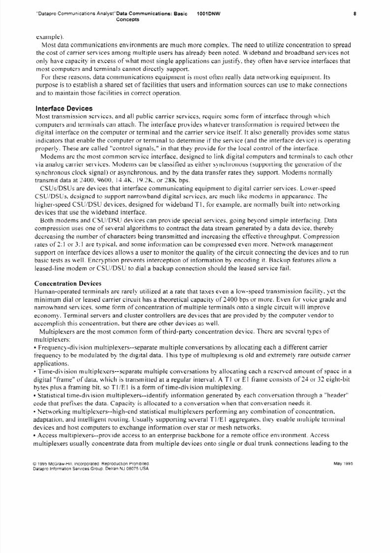
Multiplexers are the most comm on form of third-party concentration device. There are several types of
multiplexers:
l Frequency-division multiplexers--separate multiple conversations by allocating each a different carrier
frequency to be modu lated by the digital d ata. This type of multiplexing is old and extremely rare outside ca rrier
applications.
l
Time-division multiplexer+-separate multiple c onversations by allocating each a reserved am ount of space in adigital “ frame” of data, which is transmitted at a regular interval. A TI or El frame consists of 24 or 32 eight-bit
bytes p lus a framing bit, so Tl/E I is a form of time-division multiplexing.
l Statistical time-division multiplexers--identify information generated by each conversation through a “heade
code that prefixes the data. Capacity is allocated to a conversation when that conversation needs it.
0 Networking multipiexers--high-end statistical m ultiplexers performing any combination of concentration,
adaptation, and intelligent routing. Usually supporting several TI /E I aggregates, they enable multiple term ina
devices and host computers to exchange information over star or mesh networks.
l Access tnultiplexers--provide access to an enterprise backbone for a remote office environment. Access
r”
multiplexers usually concentrate data from multiple devices onto single or dual trunk connections leading to the
0 1995 McGraw-H i l l , Incorporated Reproduct lo n Proh i b i ted.
Datapro in format ion Serv ices Group, De l ran NJ 0 8 0 7 5 US A
May 1995
8/8/2019 Data 20 Communication 20Basic 20 Concepts
http://slidepdf.com/reader/full/data-20-communication-20basic-20-concepts 9/16
“Datapro Commun ications Analyst” Data Corn
Concepts
municatio ns: Basic 7001DNW
networking multiplexer. As concentrators, they perform little or no intelligent routing.
l Voice/data multiplexers--can combine both voice and data switching.
l Digital access devices such as inverse multiplexers--provide dial-up access to multiple, independent 56K or
64K bps channels, usually over a single ne twork access trunk. This capability provides variable bandw idth for a
single application or dynamically shared ban dwidth for two or more concurrknt applications.
Statistical multiplexing differs from the other strategies in that it dynamically allocates capacity. The benefit this
provides is better utilization of the shared comm unications circuit; fixed allocation of resources wastes capacity
because it is assigned to a conversation, even when it is idle.Multiplexers that operate between two points and provide the appearance of a series of dedicated circuits are
called “point-to-point” multiplexers. Multiplexers that can be used to create more complex interconnections of
circuits and switch data between them are called “ networking multiplexers” or “hubs,”
Switching Devices
The comm unications processor, usually designed for one or more vendor-specific families of compu ting and
comm unications equipme nt, performs iletwork control. intelligent routing, and concentration functions. As a
front end to a host computer, it serves as a master processor. relieving the host of the overhead involved in
messag e ha ndling and network control. As an intelligent switch, it routes messa ges across the network. either
under the control of a higher-level comm unications processor or as a peer of other intelligent switches. Remote
concentrators control a commu nity of terminals or distributed ap plication processors. gathering, queuing, and
multiplexing their transmissio ns onto one or more high-speed network trunks. These concentrators also often
provide protocol conversion and gateway functions to attached devices.
Point-to-point multiplexing of a carrier circuit is useful in sharing costs where there is a co-located commu nity
of users who need access to a common resource elsewhere. Unfortunately, this simple situation is not pervasive
in business; complex patterns of access are now the rule. Furthermore, higher-capacity circuits often need a
number of users to be justified.
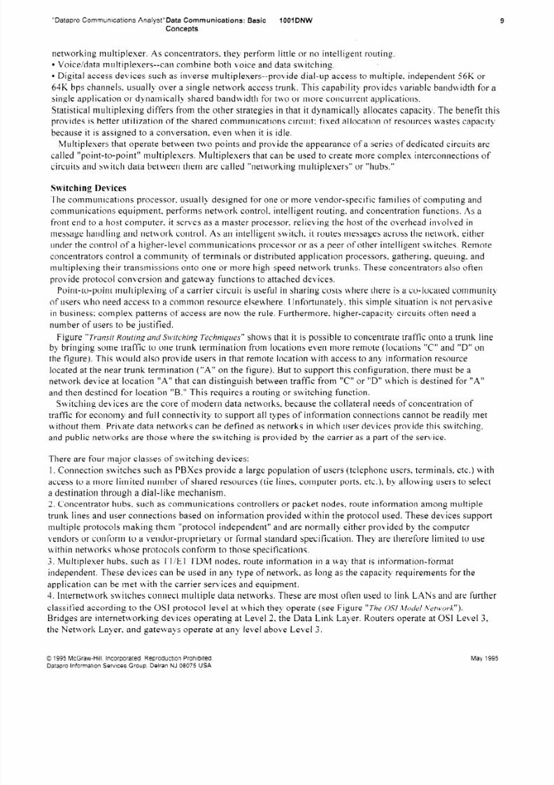
Figure “Transit Routing and Switding Techniqzres” shows that it is possible to concentrate traffic onto a trunk line
by bringing some traffic to one trunk termination from locations even more remote (locations “C” and “D” on
the figure). This would also provide users in that remote location with access to ant’ information resource
located at the near trunk term ination (“A” on the figure). B ut to support this config&ation, there mu st be a
network device at location “A” that can distinguish between traffic from “C” or “D” which is destined for “A”
and then destined for location “B.” This requires a routing or switching function.
Switching devices are the core of modern
traffic for ecoi jomy aiId ful I connect ivity to
without them. Private d ata networks can be
data networks, because the collateral need
support all types of information connectio
defined as networks in which user devices
s of concentration of
ns cannot be readily met
provide this switching,
and public n etworks are those where the switching is provided by the carrier as a part of the service.
There are four major classes of switching devices:
I. Connection switches such as PBX es provide a large population of users (telephone users, terminals, etc.) with
access to a more limited numb er of shared resources (tie lines, computer ports, etc.), by allowing users to select
a destination through a dial-like mech anism.
2. Concentrator hubs, such as comm unications controllers or packet nodes, route information amon g multiple
trunk lines and user connections based on information provided within the protocol u sed. These devices sup port
multiple protocols makin g them “protocol independent” and are normally either provided by the computervendors or conform to a vendor-proprietary or formal standa rd specification. They are therefore limited to use
within networks whose protocols conform to those specifications.
3. Multiplexer hubs, such as TI/EI TDM nodes, route information in a way that is information-format
independent. These devices can be used in any tvpe of network, as IOII~ as the capacity requirements for the
application can be met with the carrier services and equipme nt.
4. Internetwork switches connect multiple data networks. These are most often used to link LAN s and are further
classified according to the OSI protocol level at which they operate (see Figure “ The OS/ MO &/ Network”).
Bridges are internetworking devices operating at Level 2, the Data Link Layer. Routers operate at 0% Level 3,
the Network Layer, and gateways operate at any level above Level 3 .
0 1995 McGraw -Hil l, Incorpo rated R eproduct io In Proh i b i ted.
Datapro In format ion Serv ices Grou PI Delran NJ 08075 USA
May 1995
8/8/2019 Data 20 Communication 20Basic 20 Concepts
http://slidepdf.com/reader/full/data-20-communication-20basic-20-concepts 10/16
“Datapro Communications Analyst" Data Comm
Concepts
unications I: Basic 1001 DNW 10
Switching devices are often called “nodes” because they form the junctions between routes or trunks in a data
network. Because the control of node operation and routing of information will control overall information flow,
the “ managem ent” of a network is tvpically based on the mana geme nt of the nodes within it,r’
Network Monitoring and Management
Wh en an application uses a carrier circuit to connect users to information sources, the failure of that circuit will
cause the user to lose service. Because this is a localized problem. the business may elect to tolerate it for theperiod needed for the carrier to restore operation. But when a shared circuit or a node in a data netw ork fails,
many users may lose their ability to interact with information resources, and company operations may suffer.
The more complex the network. and the more shared resources are used, the greater the need for explicit
attention to service assurance mana geme nt.
There are two goals to service assura nce: restoration of acceptable service in the shortest possible time and
recomm issioning of the failed facility itself. The former can be accom plished through the use of alternate routes
for information. The latter will require identification of the specific c omponent of the network that is faulty and
the support of the provider of that compone nt.
A broader set of goals, comprising network mana geme nt as a whole, build s from the service assurance goals
listed above to include requirem ents for capacity planning for future application needs, accoun ting for network
resource usage for billing, and control of access to network and network-projected resources to prevent
unauthorized intrusions or information da mag e.
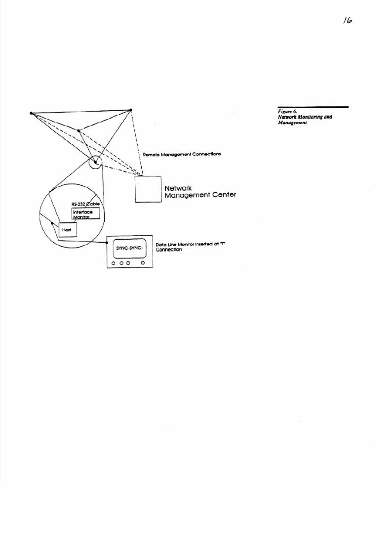
There are three basic types of tools that are applied to the meeting of network mana geme nt goals: network
monitoring systems, test systems, and network mana geme nt systems. The operation of these devices in a
network is shown in Figure “ Net-war-k Monitor-ing and Management.”
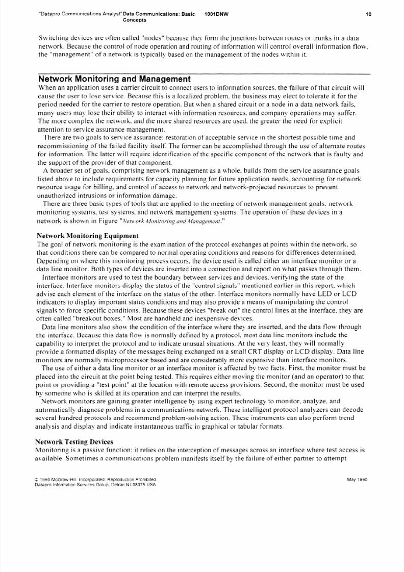
Network Monitoring Equipmen t
The goal of network monitoring is the exam ination of the protocol exchanges at points within the network, so
that conditions there can be compared to normal operating conditions and reasons for differences determined.
Depending OJ I where this monitoring process occurs, the device u sed is called either an interface monitor or a
data line monitor. Both types of devices are inserted into a connection and report on what passes through them.
Interface monitors are used to test the boundary between services and devices, verifying the state of the
interface. Interface monitors display the status of the “ control signals” mentioned earlier in this report, which
advise each element of the interface on the status of the other. Interface monitors normally have L ED or LCD
indicators to display important status conditions and may also provide a mea ns of manip ulating the control
signals to force specific conditions. Because these devices “ break out” the control lines at the interface, they are
often called “breakout boxes.” Most are handhe ld an d inexpensive devices.
Data line monitors also show the condition of the interface where they are inserted, and the data flow through
the interface. Because this data flow is normally defined by a protocol, most data line monitors include the
capability to interpret the protocol and to indicate unusua l situations. At the very least, they will normally
provide a formatted display of the messa ges being exchanged on a small CRT display or LCD display. Data line
monitors are normally microprocessor based and are considerably more expensive than interface monitors.
The use of either a data line monitor or an interface monitor is affected by two facts. First, the monitor mus t be
placed into the circuit a t the point being tested. T his requires either moving the monitor (and an operator) to that
point or providing a “test point” at the location with remote access provisions. Second. the monitor must be usedby someone who is skilled at its operation and can interpret the results.
Network monitors are gaining greater intelligence by using expert technology to monitor, analyze, and
automatically diagnose problems in a comm unications network. These intelligent protocol analyzers can decode
several hund red protocols an d recomm end problem-solving action. These instrumen ts can also perform trend
analysis and display and indicate instantaneous traffic in graphical or tabular formats.
Network Testing Devices
Monitoring is a passive function; it relies on the interception of messa ges across an interface where test access is
available. Sometim es a comm unications problem manifests itself by the failure of either partner to attempt
0 1995 McGraw-H/I I , Incorporated. Reproduct io n Proh ib t ted
Datapro In format Ion Serv ices Group, De l ran NJ 08075 USA
May 1995
8/8/2019 Data 20 Communication 20Basic 20 Concepts
http://slidepdf.com/reader/full/data-20-communication-20basic-20-concepts 11/16
“Datapro Communications Analyst”Data Communications: Basic
Concepts
IOOIDNW
comm unication at all, resulting in nothing to monitor. Whe n this happen s, or where a component of the network
is to be examined outside a connection dialog, an active testing device is needed. -
The simplest testing devices generate patterns of data. either to display o n a terminal or to “loop back” to the
source for comparison. These are often called “b it error rate” or “bit tine error rate” testers. Most are similar to
interface monitors in size and are restricted to use with very simple protocols, since they tack the intelligence to
obey complex rules for information exchange.
Data line monitors, with microprocessor intelligence, provide active testing capabilities of even complex
protocols. Called “protocol emulation,” this testing capa bility allows a user to certify the basic operation of a
device and confirm the essential characteristics of a carrier service.
Testing devices can sometim es be used by inexperienced personnel, providing that the device has a simple
“go/no go” indicator. In most cases. however, testing devices have the same constraints on usage a s apply to
network monitors.
Network Management Systems
Whe n a network device has microprocessor intelligence, it is said to be “sm art.” Such devices can often monitor
their own operation and display it on a panel or through a terminal interface. This allows the device to be
mana ged without the aid of minitoring devices. W here terminal access is provided, mana geme nt can be
exercised over a data connection from a remote location.
As the numbe r of devices in a network increases, it becomes inconvenient to maintain terminals that control
each device individually. Switching a terminal from one device to another. while theoretically practical. would
risk losing information that might be presented when the terminal is connected elsewhere. To help operators
control complex networks of many devices, num erous vendors offer network manag emen t systems. These not
only provide for the monitoring and control of many “sm art” devices, but also for the collection of data that is
useful in network planning or billing. In addition to monitoring and alarm tasks, a true network mana gemen t
system supports higher-level services. A network mana geme nt system records and processes information from
its monitors, as well as information on the network’s configuration supplied by administrators and operators.
Most element mana geme nt products are designed to control a specific device from a single vendor. Others
may control several types of devices from a given vendor. Mana geme nt systems that cross device or vendor
boundaries are called integrated m anagem ent systems.
Unti I recently. the network manag emen t system market was dominated by proprietary-based manag emen t
systems sold by LAN and internetworking device vendors. Generally, each system could only manage certainelement types. It was not uncomm on to have separate mana geme nt systems for each device class, even if all the
equipment was from the same vendor. For example. a system m ight manage modems, but not Tl CS U/DSUs.
Standa rds-based, open systems m itigate that trend. Although ha rdware vendors are still the primary suppliers
of mana geme nt systems, the systems are much more flexible since they can often control devices based on the
same standards. The Simple N etwork Management Protocol (SNM P) has been a primary focus in the rise of
standards-based management systems, but more platforms are featuring Comm on Management Information
Protocol (C MIP) a s well. Integrated mana geme nt systems help users mana ge networks by establishing a single
location to control network operations, regardless of the type and source of devices on the network.
As local area networks grow larger and are connected to one another to other resources, the need to control the
interconnected systems increases. One successful approac h is the three-tiered mana geme nt svstem. Network
nodes and devices constitute the first tier. Individual standalon e m anagem ent systems--form&g the second
tier--can still be used to control v arious resources. More frequently, however, these element manag emen tsystems--a “ manager of managers”-- occupy the third tier and provide a comm on mana geme nt interface. Many
element mana gers can link directly! with HP OpenV iew, AT&T Accum aster Integrator, IBM NetView , or Digital
DECmcc Management Stations.
Future issues in Data Communications
Network services evolve in response to the changes in dema nd and the change s in technology. Both are changing
rapidly. not only because of internal technical adv ances, such as high-speed computer chips, but because of
globalization of the marketplace and its pressure on business to expand the geographic scale of operations.
0 1995 McGraw-HI11 , Incorporated. Reproduction Prohibited.
Data pro I nformatlon Services Group, Delran NJ 08075 USA
May 1995

8/8/2019 Data 20 Communication 20Basic 20 Concepts
http://slidepdf.com/reader/full/data-20-communication-20basic-20-concepts 12/16
“Datapro Communications Analyst”Data Communications: Basic 1001 DNW
Concepts
12
Data comm unications and data networks are more than products and services. P ersonnel must plan. select,
install, and tnaintain equipm ent and coordinate services. Because data networks project computer information,
they are closely tied to computer planning and operations. Because they may utilize carrier facilities like Tl in
conjunction with voice services, data networks are also often linked to telecomm unications planning and
operations.
Many businesses have computer and comm unications organizations that have been inherited from a period
when the role of data communications was very different than it is today. In some cases, this results in a
subordination of data comm unications issues to data processing interests. In others, a “runaway” network planhas little relationship to the computers and terminals that must be served. But in most cases. defects in
organizational coordination hampe r the diagnosis of problems and the support of users.
As data networks become more critical to business, they must be placed in a reasonable planning and support
context. C omputer technology and wide area transport services are becoming less expensive daily. If the
enterprise of the future is to be dependent on networks, cost-benefit constraints of networks must be addressed in
planning. and the needs of the networked enterprise must be met in technical support.
Planning Considerations
Com panies traditionally plan network services based OII a set of dema nds presented by the information
technology and compu ting planning tasks and the constraints set by the carrier service structure in place in the
areas to be served. T his presume s that the network is relatively flexible to meet any information technology (IT)
goals and that computer technologv is relatively inflexible. Cost trends, cited above, clearly show this to be
false, even in the present.
In modern IT planning, network constraints on the compu ting systems relationships are considered as early in
the process as computer technology and sofiware constraints. The goal of most businesse s is the enterprise
network, a collection of comm unications services that will meet the information transfer dem ands for all types
of information, now and in the future.
Because comp uting relationships are changing rapidly in the face of plumm eting desktop technologv costs,
networks are increasingly supporting client/server and peer comm unications models. As shown earlie;, this
creates a need for increased connectivity along the “ fringes” of the network. The enterprise network of the future
is therefore likely to have fewer preferred information paths and be much m ore dependent on nodes and shared
trunks than was the case only a decade ago.
Increasingly, users require higher-capacity network services that are priced according to actual usage
(connection time and/or bandwidth allocated) rather than on the peak capacity available. New technologies, such
as switched digital (n x 64K bps) transmission , frame-relay data transport, Switched Multi-m egabit Data Service
(SMD S), and ATM , are enabling such services to evolve.
Broadban d networks of the future will probably have a stronger carrier compon ent, much like virtual networks
of today, b ecause of the need to concentrate the traffic of many users to create econom ical service connections.
The carrier component of broadband services is evolving from Sonet and BISDN principles. Future broadband
networks will also require local distribution of high bandw idth traffic. The local distribution strategies are
evolving from hub and FDD I principles. Somew here, the two trends must mesh.
As users plan for the future, the role of carrier “ virtual” networks for data comm unications will also become
more imp ortant. A virtual netwo rk offers users the services of a private network without the equipmen t
investment. This insulates the user against the problems of change, but it places the burden on the carrier. Users
who are totally dependent on virtual services may find that those services cannot be adapted rapidly to takeadvantage of new opportunities. A balance of risk and opportunity will be required to support the best
competitive b usiness comm unications and information processing structure.
Supporting the Network
As networks evolve and equipme nt change s, the user is often faced with rapidly changing network problems and
conditions. even when applications being supported have not changed . User frustration is increased when a
“service” facility suddenly introduces a new set of problems and support dem ands, even though no perceptible
application benefit has been gained. “ We have been running this program for four years” is a refrain often heard.
While it is often true, the fact is that the network underpinning s may hav e changed many times in that period.
0 1995 McGraw-Hr l l Incorporated Reproduct ron Proh ib t ted
Datapro In format ion Servtces Group Del ran NJ 08075 USA
May 1995

8/8/2019 Data 20 Communication 20Basic 20 Concepts
http://slidepdf.com/reader/full/data-20-communication-20basic-20-concepts 13/16

8/8/2019 Data 20 Communication 20Basic 20 Concepts
http://slidepdf.com/reader/full/data-20-communication-20basic-20-concepts 14/16
Figure 1.
Analog a nd Digital Coding Tecttniques
User Sy8t2m“A
/I
Presentation
1ession
Network
Analog Carrier Modulated
by a Digital Signal
A Digital Signal
Figure 2.
Synchnmous andAsynchronous Tmnsmission Blocking
Techniques
Time
Start and Stop Bits
Synchronous Transmission
Data Characters with No Separation of 8its
Block Start (Sync or Flag) Block End (CRC)
User System “B”
Application
RWentatiOIlI
session
Network
Network
hpofi
44Network
DataLink
Ph@d
Data Link
Physical
Data Link
Physical
Figute 3.
The O S1 Model New ark
8/8/2019 Data 20 Communication 20Basic 20 Concepts
http://slidepdf.com/reader/full/data-20-communication-20basic-20-concepts 15/16
Figure 4.
Communications N etwork
Reiuti onships and Topologies
Figure 5.
Transit Routing and Swit ching
Techniques
Host / Term inal
Relationship
Cl ient /Server Relat ionship
Intern&work Relat ionship
Peer Relutlonship
Location ‘C’l\
8 Y
D \ \\ \
\ L/
\ \
Traffic Exiting a t “ A’
A8
Location ‘B ’
A “ Switching or Routing’ Node
8/8/2019 Data 20 Communication 20Basic 20 Concepts
http://slidepdf.com/reader/full/data-20-communication-20basic-20-concepts 16/16
lb
n t
Figrvc 6,Network Monitoring amiManagement