Embed Size (px)
Citation preview

Data Acquisition ConceptsData Acquisition Concepts
Data Translation, Inc.Basics of Data Acquisition
Data Acquisition ConceptsData Acquisition Concepts
Typical data acquisition applications
• Physiological studies
• Environmental studies (temperature, etc.)
• Materials testing
• Medical research
• Quality control and testing

Data Acquisition ConceptsData Acquisition Concepts
Typical data acquisition applications
• Strain, pressure, temperature and vibration analysis
• Fluid analysis
• Manufacturing automation

Data Acquisition ConceptsData Acquisition ConceptsComponents of a data acquisition systems• Analog to digital conversion (A/D)
• Digital to analog conversion (D/A)
• Digital input/output (DIO)
• Pacer clock
Data Acquisition ConceptsData Acquisition Concepts
Analog to Digital Conversion (A/D)
• Once data has been converted from analog to digital, the digital information can then be processed by the computer, or transferred to memory
Data Acquisition ConceptsData Acquisition Concepts
Digital to Analog Conversion (D/A)
• D/A converters convert stored data back to a continuous signal (analog voltage) for display or control purposes
• Output from the D/A converter can be used to drive external devices which require an analog input
Data Acquisition ConceptsData Acquisition Concepts
Digital Input/Output (DIO)
• Used primarily for control purposes
• Used to transmit data between the host processor and an external digital device that expects to receive 1’s and 0’s
Data Acquisition ConceptsData Acquisition Concepts
Pacer Clock
• Used to initiate repetitive data conversions
• Used to control the sampling rate of conversions

Data Acquisition ConceptsData Acquisition Concepts
What is analog?
• Analog signals are “continuous” signals
• Represented by continuously changing physical quantities
• Level of signal can be increased or decreased indefinitely
• Ex. temperature, pressure, strain, voltage
Data Acquisition ConceptsData Acquisition Concepts
What is digital?
• Digital signals are “discrete” signals
• Represented by separate, individual units
• Units are represented by “bits” (binary digit)
• Bits are represented by one of two possible states: on/off, true/false, 1/0

Data Acquisition ConceptsData Acquisition Concepts
What is data acquisition?
• A method of acquiring an analog signal and converting (digitizing) it into a binary code which can be manipulated by a computer
Computer
Analog Signal
Analysis
Data Acquisition ConceptsData Acquisition Concepts
A/D Interface
• Converts analog data into digital data which can be processed
• Typical components:– Multiplexers– Amplifiers– Sample and hold circuits– A/D converters

Data Acquisition ConceptsData Acquisition Concepts
A/D Converter Functions
• Input and output (I/O)– Analog input is converted into a digital
number, by comparing the voltage with its position within the Full Scale Range
– With an n-bit A/D converter the number of output levels equals 2n – e.g. 12-bit converter = 212 = 4096

Data Acquisition ConceptsData Acquisition Concepts
Full Scale Range (FSR)
• Full scale range refers to the largest voltage range which can be input into the A/D converter

Data Acquisition ConceptsData Acquisition Concepts
Range
• Range is an input span for an A/D and D/A system
• Typical ranges are based on available sensors– Uni-polar (positive)
• 0 to 5 volts• 0 to 10 volts
• Bipolar
•-5 to +5 volts
•-10 to +10 volts

Data Acquisition ConceptsData Acquisition Concepts
Full scale range examples
+10v
0v
+10v +1.25v
-10v -1.25v
FSR = 10v FSR = 20v FSR = 2.5v

Data Acquisition ConceptsData Acquisition Concepts
Input/Output
Analog Digital(101110010011)
Data Acquisition ConceptsData Acquisition Concepts
Resolution
• Resolution determines the smallest change that can be detected
• Specified in bits. Determines number of output levels, or steps– 8 bits = 256 steps– 10 bits = 1024 steps– 12 bits = 4096 steps– 16 bits = 65,536 steps

Data Acquisition ConceptsData Acquisition Concepts
Typical Resolutions
• 8-bit – common for image capture
• 10-bit – general analog acquisition
• 12-bit – general analog acquisition
• 16-bit – precision analog acquisition
• 24-bit – high-accuracy analog acquisition
Data Acquisition ConceptsData Acquisition Concepts
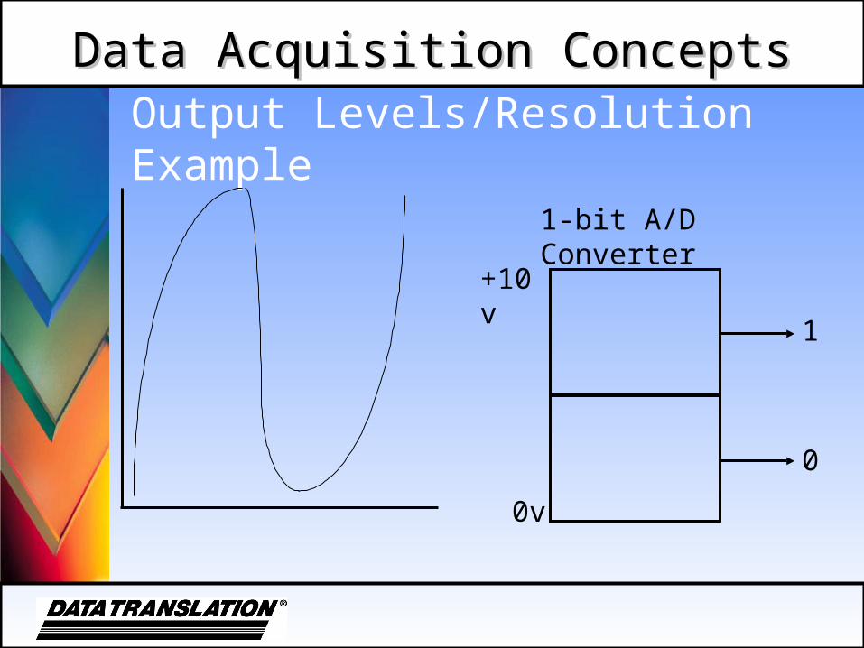
Output Levels/Resolution Example
1-bit A/D Converter
1
0
+10v
0v
Data Acquisition ConceptsData Acquisition Concepts
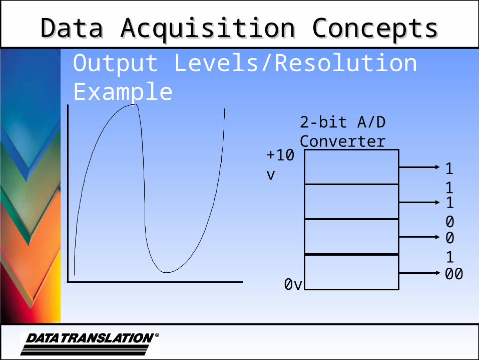
Output Levels/Resolution Example
2-bit A/D Converter
11
00
+10v
0v
10
01
Data Acquisition ConceptsData Acquisition Concepts
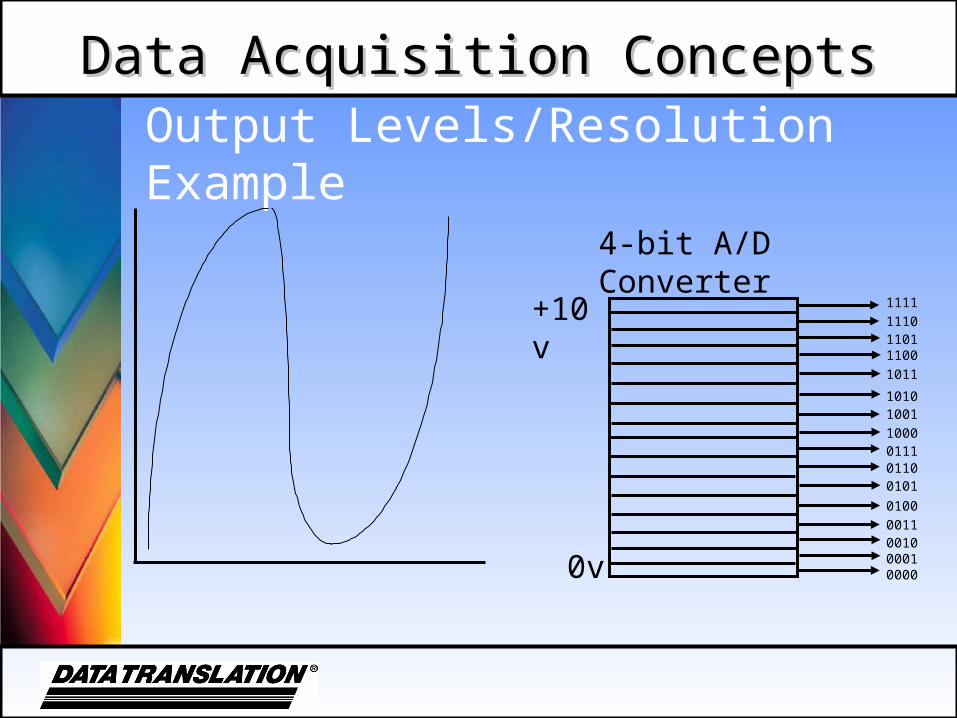
Output Levels/Resolution Example
4-bit A/D Converter
+10v
0v
1111
111011011100
1011
10101001
1000011101100101
0100
0011001000010000
Data Acquisition ConceptsData Acquisition Concepts
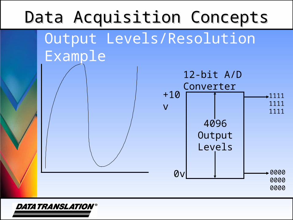
Output Levels/Resolution Example
12-bit A/D Converter
1111 1111 1111
0000 0000 0000
+10v
0v
4096 Output Levels

Data Acquisition ConceptsData Acquisition Concepts
Output Levels/Resolution Example
16-bit A/D Converter
1111 1111 1111
0000 0000 0000
+10v
0v
65,536 Output Levels

Data Acquisition ConceptsData Acquisition Concepts
LSB
• LSB stands for “least significant bit”
• An LSB represents the smallest change that can be resolved by the A/D converter
• An LSB carries the smallest value or weight
• An LSB is the rightmost bit
• LSB = Full Scale Range (FSR) ÷ 2n

Data Acquisition ConceptsData Acquisition Concepts
What affects conversion speed?
• A/D converter only
• A/D converter and related circuitry
• A/D system and host

Data Acquisition ConceptsData Acquisition Concepts
Acquisition time
• The time required to perform a complete conversion from the analog signal to digital
• The time required after receipt of “start digitizing” command until the A/D converter has finished digitizing
Data Acquisition ConceptsData Acquisition Concepts
Settling time
• Time it takes to switch to a new channel
• Each time a user switches between channels, there is a delay, referred to as settling time

Data Acquisition ConceptsData Acquisition Concepts
Throughput rate
• The inverse of A/D conversion time + acquisition time
• Measured in Hertz (Hz), which means the number of conversions per second
• The maximum rate at which the data conversion system can operate, while maintaining a specific accuracy
Data Acquisition ConceptsData Acquisition Concepts
Throughput
• Acquisition System– The acquisition system determines the
maximum throughput possible– The entire system (host, disk, A/D board,
and program) determines the practical throughput
Data Acquisition ConceptsData Acquisition Concepts
Throughput
• Throughput is specified as an aggregate of all channels– A/D runs at a constant rate– Number of channels determines
throughput per channel
• The host computer and software must be able to service the A/D board before the next conversion is complete
Data Acquisition ConceptsData Acquisition Concepts
Speeding up throughput rate
• Overlap mode - while one sample is in Sample and Hold circuitry, the next is read into the multiplexer
• Throughput equals the greater of conversion time OR acquisition time, plus any time needed for Sample and Hold switching
Data Acquisition ConceptsData Acquisition Concepts
Getting signals into the computer
• Transducers convert physical variables into electrical outputs
• An input transducer (sensor) then supplies its output to signal conditioning circuitry (on a Screw Terminal Panel)
• Signal conditioning circuitry prepares for interfacing with the PC
Data Acquisition ConceptsData Acquisition Concepts
Amplification
• The output of a sensor usually requires amplification
• Apply gain
Data Acquisition ConceptsData Acquisition Concepts
Gain
• A scale (multiplying) factor which increases an input signal to better utilize the range of the A/D converter

Data Acquisition ConceptsData Acquisition Concepts
Gain
• Gain is the amplification applied to a signal to bring it to the range of the A/D system– High Level Gains (PGH) for high level
signals – 1, 2, 4, 8– Low Level Gains (PGL) for low level
signals – 1, 10, 100, 500

Data Acquisition ConceptsData Acquisition Concepts
Selecting Gain and Range
5 volts
0 volts
0 volts
10 volts
User Input Selected Range (uni-polar)
Only 50% of the available A/D range is used.
Data Acquisition ConceptsData Acquisition Concepts
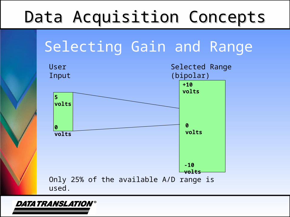
Selecting Gain and Range
5 volts
0 volts
-10 volts
+10 volts
User Input Selected Range (bipolar)
Only 25% of the available A/D range is used.
0 volts
Data Acquisition ConceptsData Acquisition Concepts
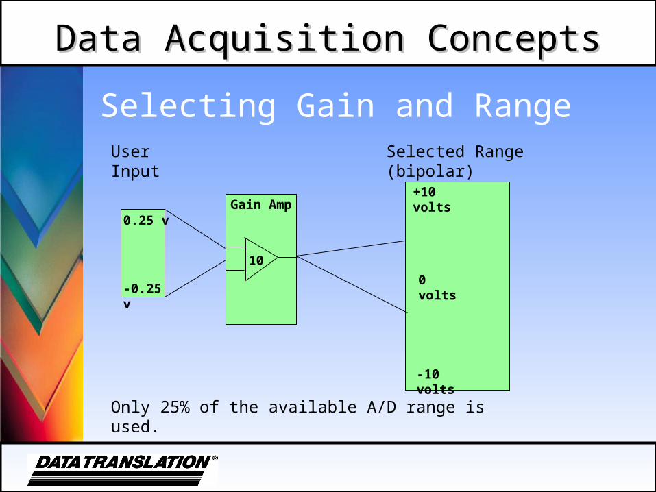
Selecting Gain and Range
0.25 v
-0.25 v
-10 volts
+10 volts
User Input Selected Range (bipolar)
Only 25% of the available A/D range is used.
0 volts
Gain Amp
10

Data Acquisition ConceptsData Acquisition Concepts
Selecting Gain and Range
1 volt
0 volts
-10 volts
10 volts
User Input Selected Range (bipolar)
Using this range only utilizes 1/20th of the range. This would allow the input to be divided into 205 increments.
0 volts

Data Acquisition ConceptsData Acquisition Concepts
Selecting Gain and Range
1 volt
0 volts
0 volts
1.25 volts
User Input Selected Range (uni-polar)
Using this range utilizes 8/10ths of the range. This would allow the input to be divided into 3277 increments.

Data Acquisition ConceptsData Acquisition Concepts
Selecting the Best Gain & Range
• Analog input and output boards are generally designed to interface to the majority of sensors that are available
• The ranges used on I/O boards may not always be appropriate for every application
Data Acquisition ConceptsData Acquisition Concepts
Selecting the Best Gain & Range
• To get the highest degree of accuracy possible out of an I/O board – try to utilize as much of the available range as possible
• Use internal or external gain selection

Data Acquisition ConceptsData Acquisition Concepts
Selecting the Best Gain & Range
• Determine the maximum range that the input signal will use
• Determine if the signal is uni-polar (above zero) or bipolar (above and below zero)
• Evaluate the available gain and range combinations to select the most appropriate product
Data Acquisition ConceptsData Acquisition Concepts
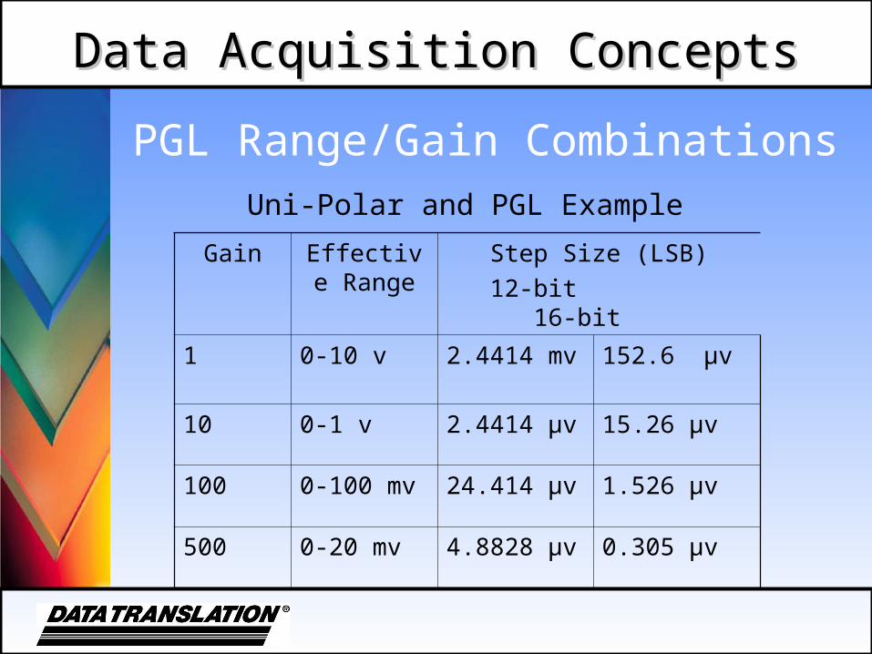
PGL Range/Gain Combinations
Gain Effective Range
Step Size (LSB)
12-bit 16-bit
1 0-10 v 2.4414 mv 152.6 µv
10 0-1 v 2.4414 µv 15.26 µv
100 0-100 mv 24.414 µv 1.526 µv
500 0-20 mv 4.8828 µv 0.305 µv
Uni-Polar and PGL Example

Data Acquisition ConceptsData Acquisition Concepts
PGL Range/Gain Combinations
Gain Effective Range
Step Size (LSB)
12-bit 16-bit
1 ± 10 v 4.8828mv 305 µv
10 ± 1 v 488.28 µv 30.5 µv
100 ± 100 mv 48.828 µv 3.05 µv
500 ± 20 mv 9.7656 µv 0.61 µv
Bipolar and PGL Example

Data Acquisition ConceptsData Acquisition Concepts
PGL Range/Gain Combinations
Gain Effective Range
Step Size (LSB)
12-bit 16-bit
1 0-10 v 2.4414 mv 152.6 µv
2 0-5 v 1.2207 mv 76.29 µv
4 0-2.5 mv 610.35 µv 38.147 µv
8 0-1.25 mv 305.17 µv 19.073 µv
Uni-Polar and PGH Example

Data Acquisition ConceptsData Acquisition Concepts
PGL Range/Gain Combinations
Gain Effective Range
Step Size (LSB)
12-bit 16-bit
1 ± 10 v 4.8828 mv 305 µv
2 ± 5 v 2.4414 mv 152.6 µv
4 ± 2.5 v 1.2207 mv 76.27 µv
8 ± 1.25 v 610.35 µv 38.147 µv
Bipolar and PGH Example
Data Acquisition ConceptsData Acquisition Concepts
Methods of Transferring Data to Memory
• Programmed input/output (PIO) – this is older technology and is slow– Polled I/O– Interrupts (shared and not shared)
• Direct memory access (DMA)

Data Acquisition ConceptsData Acquisition Concepts
Polled I/O
• Data transfer is controlled by the CPU
• CPU monitors the Data Ready bit of the A/D converter
• When data is ready, the CPU reads it, then transfers it to memory
• Very slow
Data Acquisition ConceptsData Acquisition Concepts
Direct Memory Access (DMA)
• Data is transferred directly from the data acquisition board to system memory
• Frees CPU and speeds throughput
• Board activates request line to use DMA controllers

Data Acquisition ConceptsData Acquisition Concepts
Direct Memory Access (DMA)
• DMA controller receives request, acts upon it and sends back an acknowledge to the board
• Acknowledge is received; board puts data on the bus to be stored in memory

Data Acquisition ConceptsData Acquisition Concepts
DMA: Two Methods
• Single channel for medium throughputs
• Dual channel for high throughputs
Data Acquisition ConceptsData Acquisition Concepts
Conclusion
Additional data acquisition questions? Contact Data Translation at
(800) 525-8528