Embed Size (px)
Citation preview

The IDC Engineers
Pocket Guide
Fourth Edition - Instrumentation
Automation using PLCsSCADA and Telemetry
Process Control and Data Acquisition

Process Control, Automation, Instrumentation and SCADAThe IDC Engineers Pocket Guide
Published by IDC Technologies982 Wellington StreetWEST PERTH 6005AUSTRALIA
Copyright 1994, 1995, 1996, 1997, 1998, 1999, 2000, 2003
IDC Technologies
A.B.N. 78 003 263 189
ISBN 1 875955 09 7
US English. 4th Edition.
All rights to this publication are reserved. No part of this publication may be
copied, reproduced, transmitted or stored in any form or by any means (including
electronic, mechanical, photocopying, recording or otherwise) without prior
written permission from IDC Technologies Pty Ltd.
Trademarks
All terms noted in this publication that are believed to be registered trademarks or
trademarks are listed below:
• PC-DOS, IBM, IBM PC/XT, IBM PC/AT and IBM PS/2 are registered
trademarks of International Business Machines Corporation.
• Microsoft, MS-DOS and Windows are registered trademarks of
Microsoft Corporation.
• Intel is a registered trademark of the Intel Corporation
Disclaimer
Whilst all reasonable care has been taken to ensure that the description, opinions,
listings and diagrams are accurate and workable, IDC Technologies does not
accept any legal responsibility or liability to any person, organization or other
entity for any direct loss, consequential loss or damage, however caused, that may
be suffered as a result of the use of this publication.
ForewordIDC Technologies specializes in providing high quality state-of-the-art technical
training workshops to engineers, scientists and technicians throughout the world.
More than 50,000 engineers have attended IDC's workshops over the past 10 years.
The tremendous success of the technical training workshops is based in part on
the enormous investment IDC puts into constant review and updating of the
workshops, an unwavering commitment to the highest quality standards and most
importantly - enthusiastic, experienced IDC engineers who present the workshops
and keep up-to-date with consultancy work.
The objective of this booklet is to provide today's engineer with useful technical
information and as an aide-memoir when you need to refresh your memory.
Concepts which are important and useful to the engineer, scientist and technician,
independent of discipline, are covered in this useful booklet.
Although IDC Technologies was founded in Western Australia many years ago, it
now draws engineers from all countries. IDC Technologies currently has offices
in Australia, Canada, Ireland, Malaysia, New Zealand, Singapore, South Africa,
UK and USA.
We have produced this booklet so that you will get an in-depth, practical coverage
of Communications, LANs and TCP/IP topics. Information at an advanced level
can be gained from attendance at one of IDC Technologies Practical Training
Workshops. Held across the globe, these workshops will sharpen your skills in
today's competitive engineering environment.
Other books in this series
COMMUNICATIONS Data Communications, Industrial Networking,
TCP/IP and Fiber Optics
ELECTRONICS Personal Computers, Digital Signal Processing
and Analog/Digital Conversions
ELECTRICAL Power Quality, Power Systems Protection
and Substation Automation

Process Control, Automation, Instrumentation and SCADAThe IDC Engineers Pocket Guide
ContentsChapter 1 - Automation Using PLCs
Basic Rules of Ladderlogic ..................................................................2 The Different Ladderlogic Instructions ................................................4 Restrictions in the Use of Ladderlogic Diagrams ...............................12 Number of Coils and Contacts Per Rung (or Network) ......................13
Chapter 2 - SCADA and Telemetry FundamentalsRemote Terminal Unit Structure ........................................................14 Specification of an RTU ....................................................................15 Central Site / Master Station Structure...............................................17 Station Communication Architecture and Philosophies ......................19
Chapter 3 - Process Control FundamentalsBasic Definitions ...............................................................................22 Open Loop and Feedforward Control .................................................23Closed Loop Control and Feedback ...................................................23 Loop Tuning - Some Basic Rules.......................................................24
Chapter 4 - Data Acquisition ConceptsMajor System Components ................................................................26 Aliasing and the Sampling Theorem ..................................................26 Functional Components of A/D Boards..............................................27 Analog Input Configurations..............................................................28Factors to Consider when Selecting a Data Acquisition Board...........30
Appendices Appendix A: Glossary of Terms .........................................................32Appendix B: Logic Fundamentals ......................................................64Appendix C: Number Systems ...........................................................67Appendix D: Thermocouple Tables ....................................................74Appendix E: Units and Abbreviations ................................................89 Appendix F: Commonly Used Formulae ............................................92
Who is IDC Technologies Benefits of Technical Training .........................................................100 IDC Technologies Approach to Training ..........................................100 Technical Training Workshops .........................................................101 On-site Workshops ...........................................................................104 Customized Training ........................................................................105 Locations of Past Workshops ...........................................................106 IDC Technologies Worldwide Offices ..............................................108
Process Control, Automation, Instrumentation and SCADA
1
Notes
The IDC Engineers Pocket Guide
Chapter 1Automation Using PLCs
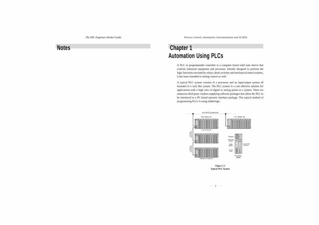
A PLC or programmable controller is a computer based solid state device that
controls industrial equipment and processes. Initially designed to perform the
logic functions executed by relays, drum switches and mechanical timer/counters,
it has been extended to analog control as well.
A typical PLC system consists of a processor and an input/output system all
mounted in a rack like system. The PLC system is a cost effective solution for
applications with a high ratio of digital to analog points in a system. There are
numerous third party vendors supplying software packages that allow the PLC to
be interfaced to a PC based operator interface package. The typical method of
programming PLCs is using ladderlogic.
Figure 1.1Typical PLC System

Process Control, Automation, Instrumentation and SCADA
3
The IDC Engineers Pocket Guide
2
The ladderlogic approach to programming is popular because of its apparent
similarity to standard electrical circuits. Two vertical lines supplying the power are
drawn at each end of the diagram with the lines of logic drawn in horizontal lines.
The example below shows the 'real world' circuit with the PLC acting as the control
device and the internal ladderlogic within the PLC.
Figure 1.2The Concept of PLC Ladderlogic
Basic Rules of Ladderlogic
The basic rules of ladderlogic can be stated as:
• The vertical lines indicate the 'Power supply' for the control system. The logical
'power flow' is visualized to move from left to right, and cannot flow from
right to left (unlike 'real' wires).
• Read the ladder diagram from top to bottom and left to right (as in the normal
Western convention of reading a book).
• Electrical devices are normally shown in their de-energized condition. This
can sometimes be confusing and special care needs to be taken to ensure
consistency.
• The contacts associated with coils, timers, counters and other instructions
have the same numbering convention as their control device.
• Devices that indicate a start operation for a particular item are normally wired
in parallel (so that any of them can start or switch the particular item on).
Figure 1.3Ladderlogic Start Operation (and Logic Diagram)
• Devices that indicate a stop operation for a particular item are normally wired
in series (so that any of them can stop or switch the particular items off).
Figure 1.4Ladderlogic Stop Operation (and Logic Diagram)
• The operation of latching is used where a momentary start input signal latches
the start signal into the ON condition; so that when the start input goes into
the OFF condition, the start signal remains energized ON. The latching
operation is also referred to as holding or maintaining a sealing contact. See
the previous two diagrams for examples of latching.

Figure 1.5Symbol for Normally Open Contact
• Normally Closed Contact
(sometimes referred to as 'Examine If Open' or 'Examine Off')
This instruction examines its memory address location for an OFF condition. If
this memory location is set to ON or 1, the instruction is set to OFF or 0. The
memory location is set to OFF or 0, the instruction is set to ON or TRUE or 1.
Figure 1.6Symbol for Normally Closed Contact
Output Energize Coil
When the complete ladderlogic rung is set to a TRUE or ON condition, the output
energize instruction sets its memory location to an ON condition; otherwise if the
ladderlogic rung is set to a FALSE or OFF condition, the output energize coil sets
its memory location to an OFF condition.
Figure 1.7Symbol for Output Energize Coil
Master Control Relays (MCR)
An example of this is given in Figure 1.8. Essentially when the MCR is energized,
the output coils for each rung following can be driven by their appropriate logic.
Whenever the MCR is de-energized, the output coils for each rung following cannot
be energized even if the appropriate logic for that coil attempts to drive it into the
energized or true state.
Process Control, Automation, Instrumentation and SCADA
5
The IDC Engineers Pocket Guide
4
• An output address status is immediately available to rungs or branches which
follow its generation.
• Interactive Logic. Ladderlogic rungs that appear later in the program often
interact with the earlier ladderlogic rungs. This useful feedback mechanism
can be used to provide feedback on successful completion of a sequence of
operations or to protect the overall system due to failure of some aspect.
The Different Ladderlogic Instructions
Ladderlogic instructions can be broken up into the following categories:
• Standard relay logic type
• Timer and counters
• Arithmetic
• Logical
• Move
• Comparison
• File manipulation
• Sequencer instructions
• Specialized analog (PID)
• Communication instructions
• Diagnostic
• Miscellaneous (sub routines, etc.)
Each of these will be briefly discussed in the following sections.
Standard Relay Logic Type
There are two main instructions in this category. They are:
- Normally Open Contact
- Normally Closed Contact
• Normally Open Contact
(sometimes referred to as 'Examine If Closed' or 'Examine On')
This instruction examines its memory address location for an ON condition. If
this memory location is set to ON or 1, the instruction is set to ON or TRUE or
1. If the location is set to OFF or 0, the instruction is set to OFF or FALSE or 0.

6
Process Control, Automation, Instrumentation and SCADA
7
The IDC Engineers Pocket Guide
6
Figure 1.8Master Control Relay
Timers
There are three main types of timers:
- Timer ON Delay
- Timer OFF Delay
- Retentive Timer
There are three parameters associated with each timer:
- The Preset Value
- The Accumulated Value
- The Time Base
• The Preset Value is the constant number of units of time that the timer 'times
to' before being energized or de-energized.
• The Accumulated Value is the number of units of time recording how long the
timer has been actively timing.
• The Time Base indicates the units of time in which the timer operates
e.g. 1 second, 0.1 seconds, 0.01 seconds, and possibly milliseconds or 0.1 minute.
The operation of the 'Timer ON' Timer is indicated in Figure 1.9 below. The Timer
output coil is activated when the accumulated time adds up to the preset value due
to the rung being energized for this period of time. Should the rung conditions go
to the false condition before the accumulator value is equal to the preset value, the
accumulator value will immediately be reset to a zero value.
Figure 1.9Operations of Time On with Timing Diagram
Count Up Counters
The counter increments the accumulator value by 1, for every transition of the
input contact from false to true. When the accumulated value equals the preset
value, the counter output will energize. When the 'enable' input is turned off or a
reset instruction is given (at the same address as the counter), the counter is reset
and the accumulated value is set to zero.
Count Down Counters
The counter decrements the accumulator value (which started off at the preset
value) by 1, for every transition of the input contact from false to true. When the
accumulator value equals zero, the counter output is energized. Counters retain
their accumulated count during a power failure.
Arithmetic Instructions
The various arithmetic instructions are based on either integer or floating point
arithmetic. The manipulation of ASCII or BCD values is sometimes also allowable.
The typical instructions available are:
• addition
• subtraction
• multiplication

Process Control, Automation, Instrumentation and SCADA
9
The IDC Engineers Pocket Guide
8
• division
• square root extraction
• convert to BCD
• convert from BCD
The rung must be true to allow the arithmetic operation.
An example is given for an addition operation in Figure 1.10.
Figure 1.10Addition Operation
Care should be taken, when using these operations, to monitor control bits such
as the carry, overflow, zero and sign bits in case of any problems. The other issue
is to ensure that floating point registers are used as destination registers, where the
source values are floating point, otherwise accuracy will be lost when performing
the arithmetic operation.
Logical Operations
Besides the logical operations that can be performed with relay contacts and coils,
which have been discussed earlier, there may be a need to do logical or Boolean
operations on a 16-bit word.
In the following examples, the bits in equivalent locations of the source words are
operated on, bit by bit, to derive the final destination value. The various logical
operations which are available are:
• AND
• OR
• XOR (Exclusive OR)
• NOT (or complement)
The appropriate rung must be true to allow the logical operation. A full explanation
of the meanings of the logical operations is given in Appendix B.
Move
This instruction moves the source value at the defined address to the destination
address every time this instruction is executed.
Figure 1.11Move Instructions
Comparison Instructions
These are useful to compare the contents of words with each other.
Typical instructions here are to compare two words for:
• equality
• not equal
• less than
• less than or equal to
• greater than
• greater than or equal to
When these conditions are true they can be connected in series with a coil which
they then drive into the energized state.
File or Block Manipulation
Words in a PLC are defined as 16-bit locations in the memory. They can be used
to store the contents of an A/D input module with 16-bit resolution or the states
of digital inputs and outputs (external or internal). A file or block on the other
hand is considered to be a collection of contiguous words. Files are also referred
to as data tables.
Typical file creations are:
• Move (word to file, file to word, file to file)
• Logical Operations (such as AND, OR, XOR, NOT)

Process Control, Automation, Instrumentation and SCADA
11
The IDC Engineers Pocket Guide
10
• Arithmetic Operations (add, subtract, multiply, divide, square root)
• Comparison Operations (equal, not equal, less than, less than or equal, greater
than, greater than or equal to)
These operations are performed on the corresponding word elements of each file:
e.g. for the addition file operation, the first word in file A is added to the first word
in file B. The result of the addition becomes the first word in the result file.
Sequencer Instruction
A ladderlogic sequencer instruction replaces the mechanical drum sequence used
in the past.
Figure 1.12Mechanical Sequence with 12 steps
When the mechanical sequence drum was rotated, 16 contacts were driven by pegs
(situated on the drum) to open and close. The sequence would move one step at a
time. Each step would have a particular pattern of pegs corresponding to the
desired state for the 16 contacts for that step. The contacts would then be used to
control external output devices.
A mask is sometimes added to the sequence for bits that may not be used.
The PLC approach
for this problem
would be to have 12
registers, with 16 bit
locations for each
step. This is shown
in Figure 1.13.
Figure 1.13Sequence Table
Sub Routines and Jump Instructions
There are two main ways of transferring control of the ladderlogic program from
the standard sequential path in which it is normally executed.
These are:
• jump to a part of the program when a rung condition becomes true
(sometimes called jump to a label or skip)
• jump to a separate block of ladderlogic called a sub routine
Jump to a Label or Skip
The JUMP instruction allows the processor to proceed to any part of the program
(either forwards [ahead] of the current JUMP instruction or backwards [behind]
the current JUMP instruction). The JUMP instruction proceeds to a defined label
when the rung on which it is situated becomes true. An example is given in the
following figure below.
Figure 1.14The Use of the JUMP and Label Instruction

Process Control, Automation, Instrumentation and SCADA
13
The IDC Engineers Pocket Guide
12
Jump to a Sub Routine
When a specific rung on which the Jump to a Sub Routine (JSR) instruction is
situated becomes true, the processor proceeds to the appropriate sub routine file.
A sub routine file is a stand-alone module of ladderlogic code which is used
repeatedly by the main program.
Figure 1.15The Sub Routine Structure
Restrictions in the Use of Ladderlogic Diagrams
Some users unwittingly run into problems with entry of a ladderlogic rung into
the PLC due to limitations in the reporting of incorrect syntax by the relevant
packages.
The typical limitations are:
• Number of Coils and Contacts Per Rung (or Network)
• Vertical Contacts
• Nesting of Contacts
• Direction of Power Flow
• Preset Value Ranges
Number of Coils and Contacts Per Rung (or Network)
Most ladderlogic implementations typically allow only one coil per rung, and a
certain maximum number of parallel branches (e.g. seven), and a certain maximum
number of series contacts (e.g. ten) per branch.
Additional rungs (with 'intermediate' coils) would have to be put in if there was a
need for more contacts than can be handled by one rung or network.
Vertical Contacts
Vertical contacts are normally not allowed.
Nesting of Contacts
Contacts may only be nested to a certain level in a PLC. In others no nesting
is allowed.
Direction of Power Flow
Within a network or rung, power always flows from left to right. Any violation of
this principle would be disallowed.
Preset Value Ranges
The maximum preset value for timers, counters, etc., varies. 9999 is a common
value, however, some smaller machines are limited to 999.

Process Control, Automation, Instrumentation and SCADA
15
The IDC Engineers Pocket Guide
14
Chapter 2SCADA and Telemetry Fundamentals
Supervisory Control and Data Acquisition (SCADA) systems have been in use in
various forms for over thirty years. Telemetry systems are a key element of a
SCADA system providing the necessary transfer of analog and digital data from
the Remote Terminal Units (RTUs) to the master stations. The term SCADA
implies that there are two activities that are necessary:
• The acquisition of data and subsequent transfer to some central location
(or group of central locations), and
• The control of some process or equipment from these central locations.
There are four components to a SCADA system:
• The central site which is the controlling station for the entire system, normally
providing the operator interface for display of information and control of
remote sites.
• The master station (or stations) which gathers data from the various sites and
which can also act as an operator interface for display of information and
control of the remote sites.
• The RTU which provides an interface to the field analog and digital signals
situated at each remote site.
• The communications system which provides the pathway for
communications between the master station and the remote site.
Remote Terminal Unit Structure
An RTU is a stand-alone data acquisition and control unit, generally
microprocessor based, which monitors and controls equipment at some remote
location from a central station. Its primary task is to control and acquire data from
process equipment at the remote location and to transfer this data back to a central
station.
Figure 2.1Schematic Diagram of a Remote Terminal Unit
Specification of an RTU
When writing a specification, the following issues should be considered:
Hardware
• Individual RTU expandability (typically up to 200 analog and digital points)
• Off the shelf modules
• Maximum number of RTU sites in a system shall be expandable to
255 maximum
• Modular system - no particular order or position in installation (of modules in
a rack)
• Robust operation - failure of one module will not affect the performance of
other modules

Process Control, Automation, Instrumentation and SCADA
17
The IDC Engineers Pocket Guide
16
• Minimisation of power consumption (CMOS can be an advantage)
• Heat generation minimized
• Robust physical construction
• Maximisation of noise immunity (due to harsh environment)
• Temperature of -10 to 65°C (operational conditions)
• Relative humidity up to 90%
• Clear indication of diagnostics
- Visible status LEDs
- Local fault diagnosis possible
- Remote fault diagnostics option
- Status of each I/O module and channel (program running / failed /
communications OK / failed)
• Modules all connected to one common bus
• Physical interconnection of modules to the bus shall be robust and suitable
for use in harsh environments
• Ease of installation of field wiring
• Ease of module replacement
• Removable screw terminals for disconnection and reconnection of wiring
Environmental Considerations
An RTU is normally installed in a remote location with fairly harsh environmental
conditions. Typically, it is specified for the following conditions:
• Ambient temperature range of 0 to +60°C (but specifications of -30°C to
+60°C are not uncommon)
• Storage temperature range of -20°C to +70°C
• Relative humidity of 0 to 95% non condensing
• Surge withstand capability to withstand power surges typically 2.5 kV, 1 MHz
for 2 seconds with 150 Ohm source impedance
• Static discharge test where 1.5 cm sparks are discharged at a distance of
30 cm from the unit
• Other requirements include dust, vibration, rain, salt and fog protection
Software (and Firmware)
• Compatibility checks of software configuration of hardware against actual
hardware available
• Log kept of all errors that occur in the system both from external events and
internal faults
• Remote access of all error logs and status registers
• Software operates continuously despite powering down or up of the system
due to loss of power supply or other faults
• Software filtering provided on all analog input channels
• Application program resides in non volatile RAM
• Configuration and diagnostic tools for:
- System setup
- Hardware and software setup
- Application code development/management/operation
- Error logs
- Remote and local operation
Central Site/Master Station Structure
Figure 2.2Typical Structure of the Master Station

Process Control, Automation, Instrumentation and SCADA
19
The IDC Engineers Pocket Guide
18
A master station has the following typical functions:
Establishment of Communications
• Configure each RTU
• Initialize each RTU with input/output parameters
• Download control and data acquisition programs to the RTU
Operation of the Communications Link
• For a master slave arrangement, poll each RTU for data and write to each
RTU
• Log alarms and events to hard disk (and operator display if necessary)
• Link inputs and outputs at different RTUs automatically
Diagnostics
• Provide accurate diagnostic information on failure of RTU and possible problems
• Predict potential problems such as data overloads
There are quite a number of important features that should be specified in a typical
SCADA system to achieve optimal operational system performance.
These are:
• system response times
• system is expandable
• system reliability (or failure) rates
• system testing
System Response Times
These should be carefully specified for the following events. Typical speeds
which are considered acceptable are:
• Display of analog or digital value (acquired from RTU) on the Master
Station Operator Display (1 to 2 seconds maximum)
• Control request from operator to RTU (1 second critical; 3 seconds non-critical)
• Acknowledgement of alarm on operator screen (1 second)
• Display of entire new display on operator screen (1 second)
• Retrieval of historical trend and display on operator screen (2 seconds)
• Sequence of events logging (at RTU) of critical events (1 millisecond)
It is important that response times are consistent over all activities of the SCADA
system. Hence the above figures are irrelevant unless the typical loading of the
system is also specified under which the above response rates will be maintained.
In addition no loss of data must occur during these peak times.
Expanding the System
A typical figure quoted in industry is that if expansion of the SCADA system is
anticipated then the current requirement of the SCADA system should not exceed
60% of the processing power of the master station. Additionally, the available
mass storage (on disk) and memory (RAM) should be approximately 50% of the
eventual size.
System Testing
The obvious requirements such as good functional specification and factory test
procedures are assumed to be met. It is important that:
• the required system performance is correctly specified
• the standard and peak load conditions should be tested
• the testing should be as close to the real conditions as possible (using
simulation software if necessary)
Station Communication Architecture & Philosophies
There are three main physical communication architectures which are discussed
below:
• Point to point
• Multiple stations
• Relay stations
Figure 2.3Point-to-Point (Two stations)

Process Control, Automation, Instrumentation and SCADA
21
The IDC Engineers Pocket Guide
20
Figure 2.4Multiple Stations
Relay Stations
There are two possibilities here.
• Store and Forward
• Talk Through Repeaters (preferably retransmitting on another frequency).
Figure 2.5Store and Forward Station
Figure 2.6Talk Through Repeaters
The most common philosophy is polled (or Master/slave). This can be used in a
point-to-point or multipoint configuration and is probably the simplest philosophy
to use. The master is in total control of the communication system and makes
regular (repetitive) requests for data and to transfer data to and from each one of
a number of slaves.

Process Control, Automation, Instrumentation and SCADA
23
The IDC Engineers Pocket Guide
22
Chapter 3Process Control Fundamentals
Process Control is a key element in the optimization of your plant and process
(using such techniques as loop tuning).
This chapter is broken down into:
• Basic Definitions
• Open Loop and Feedforward Control
• Closed Loop Control and Feedback
• Loop Tuning - some basic rules.
Basic Definitions
In a control system, the variable, we want to control, is called the ProcessVariable or PV. In industrial process control, the PV is measured by an instrument
in the field and acts as an input to an automatic controller (which is computer
based) which takes action based on the value of the PV. Alternatively the PV can
be input to computer based hardware and displayed so that the operator can perform
manual control and supervision. The variable to be manipulated, in order to have
control over the PV, is called the Manipulated Variable. If we control a particular
flow for instance, we manipulate a valve to control the flow. Here, the valve
position is called the manipulated variable and the measured flow becomes the
process variable. In the case of a simple automatic controller, the ControllerOutput Signal (OP) drives the manipulated variable. In more complex automatic
control systems, a controller output signal may not always drive a manipulated
variable in the field. In practice, the term Manipulated Variable is rarely used.
Most people involved in process control refer to the OP (output) of a controller
and it is assumed that one knows the purpose of it. The ideal value of the PV
(Process Variable) is often called Target Value. In the case of automatic control the
term Set Point Value (SP) is preferred.
Open Loop and Feedforward Control
We have open loop control, if the control action (Controller Output Signal OP) is
not a function of the PV (Process Variable). The open loop control does not
self-correct, when the PV drifts. Very often it is a control based on measured
disturbances (Feed Forward Control).
Figure 3.1Open Loop Control
The Feed Forward Control shown is Open Loop Control, where the value to be
controlled (PV) is not used to determine (or calculate) the control action. The
parameters and variables actually used for calculating the control action are those,
whose impact on the PV is known. The principle of Feed Forward Control is to
manipulate a variable of the process in such a way, that it compensates for the
impact of process disturbances.
Closed Loop Control and Feedback
We have a Closed Loop Control System if the PV, the objective of control, is used
to determine the control action. The principle is shown in Figure 3.2.
Figure 3.2Closed Loop Block Diagram
The idea of Closed Loop Control is to measure the PV (Process Variable); compare
the PV with the desired or target value, the SP (Setpoint); and determine a
control action, the OP (Output) of an automatic controller.

Process Control, Automation, Instrumentation and SCADA
25
The IDC Engineers Pocket Guide
24
In most cases, the error (ERR) is used to calculate the OP value.
ERR = PV - SP
If ERR = SP -PV has to be used, the controller has to be set for REVERSEcontrol action. Most Closed Loop Controllers are capable of controlling with
three control modes which can be used separately or together:
• Proportional Control (P)
• Integral Control (I), and
• Derivative Control (D).
The purpose of each of these control modes is as follows:
• Proportional Control ...
is the main and principal method of control. It calculates a control action
proportional to the error (ERR). Proportional control cannot eliminate the
error completely.
• Integral Control ...is the means to eliminate error completely. This may result in reduced stability
in the control action.
• Derivative Control ...adds dynamic stability to the control loop.
Loop Tuning - some basic rules
Here, we search for the critical value of controller Gain (K) which causes a
continuous oscillation of a control loop. In order to observe the process dynamic
characteristics only, we must not use any I-Control or D-Control during the
determination of the critical Gain K. We can then observe the critical frequency
matching with the 180o phase shift of the process. In addition, we know that this
value of K is the critical K of the controller. This K, multiplied with the unknown
process Gain, gives a Loop Gain of 1 for the critical frequency. From there we can
stabilize the loop by reducing K and making sure that the combined phase shift of
I-Control and D-Control still has a stabilizing phase lead.
The stages of closed loop tuning (Continuous Cycling Method) are as follows:
• Put Controller in P-Control OnlyIn order to avoid the controller influencing the assessment of the process
dynamic, no I-Control and no D-Control should be active.
• P-Control on ERR = (SP - PV)Make sure that P-Control is working with PV changes as well as with SP
changes (e.g. Equation Type A on Honeywell Controllers). This enables us to
make changes to the ERR term by changing the SP value.
• Put the Controller into Automatic ModeWe need a closed loop situation to obtain continuous cycling with critical K.
• Step Change to the SetpointA change of the SP simulates a disturbance and we can then observe how the
PV settles down. Before making a step change to the SP make sure the
process is steady with only minor dynamic fluctuations visible.
• ObservationIf the oscillations are observed settling down (or indeed there are no oscillations
at all), then double the value of K. Then repeat the previous stage called step
change to the setpoint. If the oscillations appear to be increasing, terminate
the exercise immediately and reduce K to enable the process to settle down.
Then repeat the exercise again but be more careful with high values of K. If
you have a continuous cycling of the process, measure the cycle time. The
cycle time is called Ultimate Period (Pu), and the value of K for continuous
cycling is called the Ultimate K (Ku).
• Calculation of Tuning ConstantsWe obtain different tuning constants with different combinations of
control modes.
P-Control: Kc = 0.5 * Ku
PI-Control: Kc = 0.45 * Ku, T(int) = Pu / 1.2
PID-Control: Kc = 0.6 * Ku, T(int) = Pu / 2, T(der) = Pu / 8

Process Control, Automation, Instrumentation and SCADA
27
The IDC Engineers Pocket Guide
26
Chapter 4Data Acquisition ConceptsMajor System Components
A typical data acquisition system consists of a host computer, operating software
program, data acquisition hardware, field wiring and control devices, and
transducers in the field.
An example of a PC based data acquisition system is shown in Figure 4.1.
Figure 4.1 A Typical Data Acquisition and Control System
Aliasing and the Sampling Theorem
The main objective of data acquisition is to digitize an analog signal without any
loss of information (and without introducing invalid information).
The sampling theorem states that it is important to sample a signal with a maximum
frequency component of F Hz at a minimum sampling frequency of 2F Hz.
Anything less will result in incorrect information (or aliases) being introduced
into the sampled data.
Functional Components of A/D Boards
An A/D board consists of the following components:
• the input multiplexer
• the input signal amplifier
• the sample and hold circuit
• the analog to digital converter
• the bus interface and bus timing system
The bus interface provides the mechanism for transferring the data from the board
and into the host PCs memory, and for sending any configuration information (for
example, gain/channel information) or other commands to the board. The interface
can be either 8-, 16- or 32-bit (EISA/VL/PCI buses only), and it may support
various transfer methods (polled, interrupt, DMA, block or a combination of
these). Wait state timing may be provided for use in machines with high bus
speeds or with non-standard timing.
A block diagram of a typical A/D board is given in Figure 4.2.
Figure 4.2Block Diagram of a Typical A/D Board

Process Control, Automation, Instrumentation and SCADA
29
The IDC Engineers Pocket Guide
28
Analog Input Configurations
Connection Methods
There are two methods of connecting signal sources to the data acquisition board:
• single-ended
• differential
In general, differential inputs should be used for maximum noise immunity.
Single-ended inputs should only be used where it is impossible to use either of the
other two methods.
Single-Ended Inputs
Boards which accept single-ended inputs have a single input wire for each signal,
the source's HI side. All the LO sides of the sources are commoned and connected
to the analog ground AGND pin. This input type suffers from loss of common
mode rejection and is very sensitive to noise. It is not recommended for long leads
(longer than 1/2 m) or for high gains (greater than 5x). The advantage of this
method is that it allows the maximum number of inputs, is simple to connect (only
one common or ground lead necessary) and it allows for simpler A/D front end
circuitry. We can see from Figure 4.3 that because the amplifier LO (negative)
terminal is connected to AGND, what is amplified is the difference between
ES0 + VCM and AGND, and this introduces the common mode offset as an error into
the readings. Some boards do not have an amplifier, and the multiplexer output is
fed straight to the A/D. Single-ended inputs must be used with these type of
boards.
Figure 4.3Eight Single-Ended Inputs
Differential Inputs
True differential inputs provide the maximum noise immunity. This method must
also be used where the signal sources have different ground points and cannot be
connected together. Referring to Figure 4.4, we see that each channel's individual
common mode voltage is fed to the AMP LO terminal; the individual VCMn voltages
are thus subtracted on each reading.
Note that two input multiplexers are needed, and for the same number of input
terminals as single-ended, only half the number of input channels are available in
differential mode. Also, bias resistors may be required to reference each input
channel to ground. This depends on the board's specifications (the manual will
explain the exact requirements) but it normally consists of one large resistor
connected between each signal's LO side and AGND (at the signal end of the
cable) and sometimes it requires another resistor of the same value between the
HI side and AGND.
Figure 4.4Four Differential Inputs
Note that VCM and VCMN voltages may be made up of a DC part and possibly a
time-varying AC part. This AC part is called noise, but we can see that using
differential inputs, the noise part will also tend to be cancelled out (rejected)
because it is present on both inputs of the input amplifier.

Process Control, Automation, Instrumentation and SCADA
31
The IDC Engineers Pocket Guide
30
Factors to Consider when Selecting a Data Acquisition Board
The following is a checklist of issues to consider when selecting a data acquisition
board for an application.
Board Throughput
• A/D converter speed
• Rated maximum throughput
• Typical overall throughput bearing in mind host computer and software to
be used
Analog Inputs
• Resolution (12-bit or 16-bit)
• Accuracy, non-linearity, gain error (in LSB e.g. ± 1 LSB)
• Input type (current/voltage/frequency)
• Typical ranges 0 to 10 V, -5 V to +5 V, 0 to +5 V
• Software-selectable input ranges
• Unipolar/bipolar inputs
• Individual gains per channel
• Range of gains selectable
• Accuracy and throughput at high gains
• Maximum input signal frequency
• Simultaneous sampling
Number of Channels
• Input type (single-ended, pseudo-differential, differential)
• Direct thermocouple connection (cold junction compensation)
• Strain gauge inputs
• Overload protection
• Channel-to-channel isolation
• Calibration, automatic/trimpots
On-board Features for A/D Section
• Triggering (external analog/digital)
• Pre-, post- mid-trigger
• External trigger/gate
• Pacer clock
• Burst scan triggering
• Channel-gain array
Analog Outputs
• Number of channels
• Resolution (8-, 12- or 16-bit)
• Noise level (Signal/Noise)
• Unipolar/bipolar ranges
• Output span (±5 V, ±12 V, 0 to 8 V, etc)
• Voltage or current
• Jumper settings/software programmable
• Output protection (maximum short duration voltage)
• Maximum loading (output current)
• Remote sense/output force
• Conversion speed
• On-board memory (to generate complex waveforms)
• Simultaneous updating
• Pacer clock

Process Control, Automation, Instrumentation and SCADA
33
Algorithm Can be used as a basis for writing a computer program. This is a setof rules with a finite number of steps for solving a problem.
Alias Frequency A false lower frequency component that appears in data reconstructedfrom original data acquired at an insufficient sampling rate (less than two times the maximum frequency of the original data).
ALU see Arithmetic Logic Unit.
Amplitude Modulation A modulation technique (also referred to as AM or ASK) used to allow data to be transmitted across an analog network, such as a switched telephone network. The amplitude of a single (carrier) frequency is varied or modulated between two levels; one for binary 0 and one for binary 1.
Analog A continuous real-time phenomenon in which the information values are represented in a variable and continuous waveform.
Analog Input Board Printed Circuit Board which converts incoming analog signals to digital values.
ANSI American National Standards Institute. The principle standards development body in the USA.
Apogee The point in an elliptical orbit that is furtherest from earth.
Appletalk A proprietary computer networking standard initiated by Apple Computer for use in connecting the Macintosh range of computers and peripherals (including Laser Writer printers).
This standard operates at 230 kilobits/second.
Application Program A sequence of instructions written to solve a specific problem facingorganisational management.
These programs are normally written ina high-level language and draw on resources of the operating systemand the computer hardware in executing its tasks.
Application Layer The highest layer of the seven layer ISO/OSI Reference Model structure, which contains all user or application programs.
Arithmetic Logic Unit The element(s) in a processing system that perform(s) the mathematical functions such as addition, subtraction, multiplication, division,inversion, AND, OR, NAND and NOR.
ARP Address Resolution Protocol. A Transmission Control Protocol/ Internet Protocol (TCP/IP) process that maps an IP address to Ethernet address, required by TCP/IP for use with Ethernet.
ARQ Automatic Request for Transmission. A request by the receiver for the transmitter to retransmit a block or a frame because of errors detected in the originally received message.
AS Australian Standard.
The IDC Engineers Pocket Guide
32
Appendix AGlossary of Terms
10BASE2 IEEE802.3 (or Ethernet) implementation on thin coaxial cable (RG58/AU).
10BASE5 IEEE802.3 (or Ethernet) implementation on thick coaxial cable.
10BASET IEEE802.3 (or Ethernet) implementation on unshielded 22 AWG twisted pair cable.
A/D Conversion Time This is the length of time a board requires to convert an analog signal into a digital value. The theoretical maximum speed (conversions/ second) is the inverse of this value. See Speed/Typical Throughput.
A/D Analog to Digital conversion.
Absolute Addressing A mode of addressing containing both the instruction and location(address) of data.
Accuracy Closeness of indicated or displayed value to the idealmeasured value.
ACK Acknowledge (ASCII - control F).
Acknowledge A handshake line or protocol code which is used by the receivingdevice to indicate that it has read the transmitted data.
Active Device Device capable of supplying current for a loop.
Active Filter A combination of active circuit devices (usually amplifiers), with passive circuit elements (resistors and capacitors), which have characteristics that more closely match ideal filters than do passive filters.
Actuator Control element or device used to modulate (or vary) a process parameter.
Address A normally unique designator for location of data or the identity of a peripheral device which allows each device on a single communications line to respond to its own message.
Address Register A register that holds the address of a location containing a data item called for by an instruction.
AFC Automatic Frequency Control. The circuit in a radio receiver that automatically keeps the carrier frequency centred in the passband ofthe filters and demodulators.
AGC Automatic Gain Control. The circuit in a radio that automatically keeps the carrier gain at the proper level.

Process Control, Automation, Instrumentation and SCADA
35
Bandwidth The range of frequencies available, expressed as the difference between the highest and lowest frequencies, in hertz (cycles per second, abbreviated Hz).
Bar Code Symbol An array of rectangular parallel bars and spaces of various widths designed for the labelling of objects with unique identifications. A bar code symbol contains a leading quiet zone, a start character,one or more data characters including, in some cases, a check character, a stop character, and a trailing quiet zone.
Base Address A memory address that serves as the reference point. All other points are located by offsetting in relation to the base address.
Base Band Base Band operation is the direct transmission of data over a transmission medium without the prior modulation on a high frequency carrier band.
Base Loading An inductance situated near the bottom end of a vertical antenna to modify the electrical length. This aids in impedance matching.
Baud Unit of signalling speed derived from the number of events per second (normally bits per second). However, if each event has more than onebit associated with it, the baud rate and bits per second are not equal.
Baudot Data transmission code in which five bits represent one character. Sixty-four alphanumeric characters can be represented.
BCC Block Check Character. Error checking scheme with one check character; a good example being Block Sum Check.
BCD Binary Coded Decimal. A code used for representing decimal digitsin a binary code.
BEL Bell (ASCII for control-G).
BERT/BLERT Bit Error Rate/Block Error Rate Testing. An error checking technique that compares a received data pattern with a known transmitted data pattern to determine transmission line quality.
Bifilar Two conducting elements used in parallel (such as two parallel wires wound on a coil form).
Binary Coded Decimal (BCD) A code used for representing decimal digits in a binary code.
BIOS The basic input/output system for the computer, usually firmware-based. This program handles the interface with the PC hardware and isolates the Operating Software (OS) from the low-level activities of the hardware. As a result, application software becomes moreindependent of the particular specifications of the hardware on whichit runs, and hence more portable.
The IDC Engineers Pocket Guide
34
ASCII American Standard Code for Information Interchange. A universalstandard for encoding alphanumeric characters into 7 or 8 binary bits. Drawn up by ANSI to ensure compatibility between differentcomputer systems.
ASIC Application Specific Integrated Circuit.
ASK Amplitude Shift Keying. See Amplitude Modulation.
ASN.1 Abstract Syntax Notation One. An abstract syntax used to definethe structure of the protocol data units associated with a particularprotocol entity.
Asynchronous Communications in which characters can be transmitted at an arbitrary,unsynchronised time, and where the time intervals between transmittedcharacters may be of varying lengths.
Communication is controlled by start and stop bits at the beginning and end of each character.
Attenuation The decrease in signal magnitude or strength between two points.
Attenuator A passive network that decreases the amplitude of a signal (without introducing any undesirable characteristics to the signals such as distortion).
AUI CABLE Attachment Unit Interface Cable. Sometimes called the drop cable to attach terminals to the transceiver unit.
Auto Tracking Antenna A receiving antenna that moves in synchronism with the transmittingdevice which is moving (such as a vehicle being telemetered).
Autoranging An autoranging board can be set to monitor the incoming signal and automatically select an appropriate gain level based on the previous incoming signals.
AWG American Wire Gauge.
Background Program An application program that can be executed whenever the facilities of the system are not needed by a higher priority program.
Backplane A panel containing sockets into which circuit boards (such as I/O cards, memory boards and power supplies) can be plugged.
Balanced Circuit A circuit so arranged that the impressed voltages on each conductor of the pair are equal in magnitude but opposite in polarity with respect to a defined reference.
Band Pass Filter A filter that allows only a fixed range of frequencies to pass through. All other frequencies outside this range (or band) are sharply reduced in magnitude.
Band Reject A circuit that rejects a defined frequency band of signals while passing all signals outside this frequency range (both lower than and higher than).

Process Control, Automation, Instrumentation and SCADA
37
Bubble Memory Describes a method of storing data in memory where data is represented as magnetised spots called magnetic domains that rest on a thin film of semiconductor material. Normally used in high-vibration, high-temperature or otherwise harsh industrial environments.
Buffer An intermediate temporary storage device used to compensate for a difference in data rate and data flow between two device (also called a spooler for interfacing a computer and a printer).
Burst Mode A high speed data transfer in which the address of the data is sent followed by back to back data words while a physical signal is asserted.
Bus A data path shared by many devices, with one or more conductors for transmitting signals, data or power.
Byte A term referring to eight associated bits of information; sometimes called a "character".
Cache Memory A fast buffer memory that fits between the CPU and the slower main memory to speed up CPU requests for data.
Capacitance (mutual) The capacitance between two conductors with all other conductors,including shield, short circuited to the ground.
Capacitance Storage of electrically separated charges between two plates having different potentials. The value is proportional to the surface area of the plates and inversely proportional to the distance between them.
Cascade Two or more electrical circuits in which the output of one is fed into the input of the next one.
Cassegrain Antenna Parabolic antenna that has a hyperbolic passive reflector situated at the focus of the parabola.
CCD Charge-Coupled Device (camera).
CCIR Comité Consultatif Internationale des Radiocommunications.
CCITT Consultative Committee International Telegraph and Telephone. An international association that sets worldwide standards (e.g. V.21,V.22, V.22bis).
Cellular Polyethylene Expanded or "foam" polyethylene consisting of individual closed cells suspended in a polyethylene medium.
CGA Color Graphics Adapter. A computer standard utilising digitalsignals offering a resolution of 320 by 200 pixels and a palette of 16 colors.
Channel Selector In an FM discriminator the plug-in module which causes the device to select one of the channels and demodulate the subcarrier to recover data.
Character Letter, numeral, punctuation, control figure or any other symbol contained in a message.
The IDC Engineers Pocket Guide
36
Bipolar Range / Inputs A signal range that includes both positive and negative values. Bipolar inputs are designed to accept both positive and negative voltages. (Example: ±5 V).
Bisynchronous Transmission See BSC.
Bit Stuffing with A technique used to allow pure binary data to be transmitted on aZero Bit Insertion synchronous transmission line. Each message block (frame) is
encapsulated between two flags which are special bit sequences. Then if the message data contains a possibly similar sequence, an additional (zero) bit is inserted into the data stream by the sender,and is subsequently removed by the receiving device. The transmission method is then said to be data transparent.
BIT (Binary Digit) Derived from "BInary DigiT", a one or zero condition in the binary system.
Bits & Bytes One bit is one binary digit, either a binary 0 or 1. One byte is the amount of memory needed to store each character of information (text or numbers). There are eight bits to one byte (or character),and there are 1024 bytes to one kilobyte (KB). There are 1024 kilobytes to one megabyte (MB).
Block In block-structured programming languages, a section of programming languages or a section of program coding treated as a unit.
Block Sum Check This is used for the detection of errors when data is being transmitted. It comprises a set of binary digits (bits) which are the modulo 2 sum of the individual characters or octets in a frame (block) or message.
BNC Bayonet type coaxial cable connector.
bps Bits per second. Unit of data transmission rate.
Bridge A device to connect similar sub-networks without its own network address. Used mostly to reduce the network load.
Broad Band A communications channel that has greater bandwidth than a voice grade line and is potentially capable of greater transmission rates.
Broadcast A message on a bus intended for all devices which requires no reply.
BS Backspace (ASCII Control-H).
BS British Standard.
BSC Bisynchronous Transmission. A byte or character oriented communication protocol that has become the industry standard(created by IBM). It uses a defined set of control characters for synchronised transmission of binary coded data between stations in a data communications system.

Process Control, Automation, Instrumentation and SCADA
39
Conical Scan Antenna An automatic tracking antenna system in which the beam is steered in a circular path so that it forms a cone.
Contention The facility provided by the dial network or a data PABX which allows multiple terminals to compete on a first come, first served basis for a smaller number of computer ports.
Control System A system in which a series of measured values are used to make a decision on manipulating various parameters in the system to achieve a desired value of the original measured values.
Convolution An image enhancement technique in which each pixel is subjected to a mathematical operation that groups it with its nearest neighbours and calculates its value accordingly.
Correlator A device which compares two signals and indicates the similarity between the two signals.
Counter/ Timer Trigger On-board counter/timer circuitry can be set to trigger data acquisition at a user-selectable rate and for a particular length of time.
Counter Data Register The 8-bit register of an (8254 chip) timer/counter that corresponds to one of the two bytes in the counter's output latch for read operations and count register for write operations.
CPU Central Processing Unit.
CR Carriage Return (ASCII control-M).
CRC Cyclic Redundancy Check. An error-checking mechanism using a polynomial algorithm based on the content of a message frame at the transmitter and included in a field appended to the frame. At thereceiver, it is then compared with the result of the calculation that is performed by the receiver. Also referred to as CRC-16.
Cross Talk A situation where a signal from a communications channel interfereswith an associated channel's signals.
Crossed Pinning Wiring configuration that allows two DTE or DCE devices to communicate. Essentially it involves connecting pin 2 to pin 3 of the two devices.
Crossover In communications, a conductor which runs through the cable and connects to a different pin number at each end.
Crosstalk A situation where a signal from a communications channel interferes with an associated channel's signals.
CSMA/CD Carrier Sense Multiple Access/Collision Detection.
When two devices transmit at the same time on a local areanetwork,they both cease transmission and signal that a collision has occurred. Each then tries again after waiting for a random timeperiod.
The IDC Engineers Pocket Guide
38
Characteristic Impedance The impedance that, when connected to the output terminals of a transmission line of any length, makes the line appear infinitely long. The ratio of voltage to current at every point along a transmission line on which there are no standing waves.
Clock The source of timing signals for sequencing electronic events such as synchronous data transfer or CPU operation in a PC.
Clock Pulse A rising edge, then a falling edge (in that order) such as applied to the clock input of an 8254 timer/counter.
Clock The source(s) of timing signals for sequencing electronic events eg synchronous data transfer.
Closed Loop A signal path that has a forward route for the signal, a feedback network for the signal and a summing point.
CMRR Common Mode Rejection Ratio - A data acquisition’s board's ability to measure only the voltage difference between the leads of atransducer, rejectingwhat the leads have in common. The higher theCMRR, the better the accuracy.
CMV Common Mode Voltage.
CNR Carrier to Noise Ratio. An indication of the quality of the modulated signal.
Cold-junction Thermocouple measurements can easily be affected by the interface Compensation the thermocouples are connected to. Cold-junction compensation
circuitry compensates for inaccuracies introduced in the conversion process.
Collector The voltage source in a transistor with the base as the control source and the emitter as the controlled output.
Collision The situation when two or more LAN nodes attempt to transmit atthe same time.
Common Carrier A private data communications utility company that furnishes communications services to the general public.
Common Mode Signal The common voltage to the two parts of a differential signal applied to a balanced circuit.
Commutator A device used to effect time-division multiplexing by repetitive sequential switching.
Compiler A program to convert high-level source code (such as BASIC) to machine code-executable form, suitable for the CPU.
Composite Link The line or circuit connecting a pair of multiplexers or concentrators;the circuit carrying multiplexed data.
Composite A video signal that contains all the intensity, color and timing information necessary for a video product.

Process Control, Automation, Instrumentation and SCADA
41
Decoder A device that converts a combination of signals into a single signal representing that combination.
Decommutator Equipment for the demultiplexing of commutated signals.
Default A value or setup condition assigned automatically unless anotheris specified.
Delay Distortion Distortion of a signal caused by the frequency components making up the signal having different propagation velocities across a transmission medium.
DES Data Encryption Standard.
Deviation A movement away from a required value.
DFB Display Frame Buffer.
Diagnostic Program A utility program used to identify hardware and firmware defects related to the PC.
Dielectric Constant (E) The ratio of the capacitance using the material in question as the dielectric, to the capacitance resulting when the material is replaced by air.
Differential See Number of channels.
Digital A signal which has definite states (normally two).
Digitise The transformation of an analog signal to a digital signal.
DIN Deutsches Institut Fur Normierung.
DIP Acronym for dual in line package referring to integrated circuits and switches.
Diplexing A device used to allow simultaneous reception or transmission of two signals on a common antenna.
Direct Memory Access A technique of transferring data between the computer memory and a device on the computer bus without the intervention of the micro-processor. Also abbreviated to DMA.
Discriminator Hardware device to demodulate a frequency modulated carrier or subcarrier to produce analog data.
Dish Antenna An antenna in which a parabolic dish acts a reflector to increase the gain of the antenna.
Dish Concave antenna reflector for use at VHF or higher frequencies.
Diversity Reception Two or more radio receivers connected to different antennas to improve signal quality by using two different radio signals to transfer the information.
DLE Data Link Escape (ASCII character).
DMA Direct Memory Access.
The IDC Engineers Pocket Guide
40
Current Sink This is the amount of current the board can supply for digital outputsignals. With 10-12 mA or more of current sink capability, a board can turn relays on and off. Digital I/O boards with less than 10-12 mA of sink capability are designed for data transfer only, not for hardware power relay switching.
Current Loop A communication method that allows data to be transmitted over a longer distance with a higher noise immunity level than with the standard RS-232C voltage method.
A mark (a binary 1) is represented by current; and a space(or binary 0) is represented by the absence of current.
Current Inputs A board rated for current inputs can accept and convert analog current levels directly, without conversion to voltage.
D/A Digital to Analog.
DAS Data Acquisition System.
Data Integrity A performance measure based on the rate of undetected errors.
Data Reduction The process of analysing a large quantity of data in order to extract some statistical summary of the underlying parameters.
Data Link Layer This corresponds to layer 2 of the ISO Reference Model for opensystems interconnection. It is concerned with the reliable transfer of data (no residual transmission errors) across the data linkbeing used.
Data Integrity A performance measure based on the rate of undetected errors.
Datagram A type of service offered on a packet-switched data network. A datagram is a self contained packet of information that is sent through the network with minimum protocol overheads.
dBi A unit that is used to represent the gain of an antenna compared to the gain of an isotropic radiator.
dBm A signal level that is compared to a 1-mW reference.
dBmV A signal amplitude that is compared to a 1-mV reference.
dBW A signal amplitude that is compared to a 1-Watt reference.
DCE Data Communications Equipment. Devices that provide the functionsrequired to establish, maintain and terminate a data transmissionconnection. Normally it refers to a modem.
Decibel A logarithmic measure of the ratio of two signal levels where dB = 20log10 V1/V2. Being a ratio, it has no units of measure.
Decibel (dB) A logarithmic measure of the ratio of two signal levels where dB = 20log10 V1/V2 or where dB = 10log10 P1/P2 and where V refers to Voltage or P refers to Power. Note that it has no unit of measure.

Process Control, Automation, Instrumentation and SCADA
43
EIA-232-C Interface between DTE and DCE, employing serial binary data exchange. Typical maximum specifications are 15m at 19200 Baud.
EIA-423 Interface between DTE and DCE, employing the electrical characteristics of unbalanced voltage digital interface circuits.
EIA-449 General purpose 37 pin and 9 pin interface for DCE and DTE employing serial binary interchange.
EIA-485 The recommended standard of the EIA that specifies the electrical characteristics of drivers and receivers for use in balanced digital multipoint systems.
EIRP Effective Isotropic Radiated Power. The effective power radiated from a transmitting antenna when an isotropic radiator is used to determine the gain of the antenna.
EISA Enhanced Industry Standard Architecture.
EMI/RFI Electro-Magnetic Interference or Radio Frequency Interference. Background 'noise' capable of modifying or destroying data transmission.
EMS Expanded Memory Specification.
Emulation The imitation of a computer system performed by a combination of hardware and software that allows programs to run between incompatible systems.
Enabling The activation of a function of a device by a defined signal.
Encoder A circuit which changes a given signal into a coded combination for purposes of optimum transmission of the signal.
ENQ Enquiry (ASCII Control-E).
EOT End of Transmission (ASCII Control-D).
EPROM Erasable Programmable Read Only Memory. Non-volatile semiconductor memory that is erasable in a ultra violet light and reprogrammable.
Equaliser The device which compensates for the unequal gain characteristic of the signal received.
Error Rate The ratio of the average number of bits that will be corrupted to the total number of bits that are transmitted for a data link or system.
Error The difference between the setpoint and the measured value.
ESC Escape (ASCII character).
ESD Electrostatic Discharge.
Ethernet Name of a widely used Local Area Network (LAN), based on the CSMA/CD bus access method (IEEE 802.3).
ETX End of Text (ASCII control-C).
The IDC Engineers Pocket Guide
42
DNA Distributed Network Architecture.
Doppler The change in observed frequency of a signal caused by the emitting device moving with respect to the observing device.
Downlink The path from a satellite to an earth station.
DPI Dots per Inch.
DPLL Digital Phase Locked Loop.
DR Dynamic Range. The ratio of the full scale range (FSR) of a data converter to the smallest difference it can resolve. DR = 2n wheren is the resolution in bits.
DRAM Dynamic Random Access Memory. See RAM.
Drift A gradual movement away from the defined input/output condition over a period of time.
Driver Software A program that acts as the interface between a higher level coding structure and the lower level hardware/firmware component of a computer.
DSP Digital Signal Processing.
DSR Data Set Ready. An RS-232 modem interface control signal which indicates that the terminal is ready for transmission.
DTE Data Terminal Equipment. Devices acting as data source, data sink,or both.
Dual-ported RAM Allows acquired data to be transferred from on-board memory to the computer's memory while data acquisition is occurring.
Duplex The ability to send and receive data over the same communications line.
Dynamic Range The difference in decibels between the overload or maximum and minimum discernible signal level in a system.
EBCDIC Extended Binary Coded Decimal Interchange Code. An 8-bit character code used primarily in IBM equipment. The code allows for 256 different bit patterns.
EEPROM Electrically Erasable Programmable Read Only Memory. This memory unit can be erased by applying an electrical signal to the EEPROM and then reprogrammed.
EGA Enhanced Graphics Adapter. A computer display standard that provides a resolution of 640 by 350 pixels, a palette of 64 colors, and the ability to display as many as 16 colors at one time.
EIA Electronic Industries Association. An organisation in the USA specialising in the electrical and functional characteristics of interface equipment.

Process Control, Automation, Instrumentation and SCADA
45
Frame Grabber An image processing peripheral that samples, digitises and stores a camera frame in computer memory.
Frequency Modulation A modulation technique (abbreviated to FM) used to allow data to be transmitted across an analog network where thefrequency is varied between two levels - one for binary '0' andone for binary '1'.
Also known as Frequency Shift Keying (or FSK).
Frequency Refers to the number of cycles per second.
Frequency Domain The displaying of electrical quantities versus frequency.
Fringing The unwanted bordering of an object or character with weak colors when there should be a clearly delineated edge.
Full Duplex Simultaneous two way independent transmission in both directions (4 wire). See Duplex.
G Giga (metric system prefix - 109).
Gain of Antenna The difference in signal strengths between a given antenna and a reference isotropic antenna.
Gain Amplification; applied to an incoming signal, gain acts as a multiplication factor on the signal, enabling a board to use signals that would otherwise be too weak.
For example, when set to a gain of 10, a board with a range of +5 V can use raw input signals as low as +0.5 V (+500 mV); with a gainof 20, the range extends down to +250 mV.
Gateway A device to connect two different networks which translates the different protocols.
Genlock This is the process of synchronising one video signal to a master reference, ensuring that all signals will be compatible or related to one another.
Geostationary A special earth orbit that allows a satellite to remain in a fixed position above the equator.
Geosynchronous Any earth orbit in which the time required for one revolution of a satellite is an integral portion of a sidereal day.
GPIB General Purpose Interface Bus. An interface standard used for paralleldata communication, usually used for controlling electronic instruments from a computer. Also designated IEEE-488 standard.
Graphics Mode In graphics mode each pixel on a display screen is addressable, and each pixel has a horizontal (or X) and a vertical (or Y) co-ordinate.
Grey Scale In image processing, the range of available grey levels. In an 8-bit system, the grey scale contains values from 0 to 255.
The IDC Engineers Pocket Guide
44
Even Parity A data verification method normally implemented in hardware in which each character (and the parity bit) must have an even number of ON bits.
External Pulse Trigger Many of the A/D boards allow sampling to be triggered by a voltage pulse from an external source.
Fan In The load placed on a signal line by a logic circuit input.
Fan Out The measure of drive capability of a logic circuit output.
Farad Unit of capacitance whereby a charge of one coulomb produces a one volt potential difference.
FCC Federal Communications Commission (USA).
FCS Frame Check Sequence. A general term given to the additional bits appended to a transmitted frame or message by the source to enable the receiver to detect possible transmission errors.
FDM Frequency Division Multiplexer. A device that divides the available transmission frequency range in narrower bands, each of which is used for a separate channel.
Feedback A part of the output signal being fed back to the input of the amplifier circuit.
Field One half of a video image (frame) consisting of 312.5 lines (for PAL). There are two fields in a frame. Each is shown alternately every 1/25 of a second (for PAL).
FIFO First in, First Out.
Filled Cable A telephone cable construction in which the cable core is filled witha material that will prevent moisture from entering or passing along the cable.
FIP Factory Instrumentation Protocol.
Firmware A computer program or software stored permanently in PROM or ROM or semi-permanently in EPROM.
Flame Retardancy The ability of a material not to propagate flame once the flame source is removed.
Floating An electrical circuit that is above the earth potential.
Flow Control The procedure for regulating the flow of data between two devices preventing the loss of data once a device's buffer has reachedits capacity.
Frame A full video image comprising two fields. A PAL frame has a total of 625 lines (an NTSC frame has 525 lines).
Frame The unit of information transferred across a data link. Typically,there are control frames for link management and information frames for the transfer of message data.

Process Control, Automation, Instrumentation and SCADA
47
HPIB Hewlett-Packard Interface Bus; trade name used by Hewlett-Packardfor its implementation of the IEEE-488 standard.
I/O Address A method that allows the CPU to distinguish between different boards in a system. All boards must have different addresses.
IEC International Electrotechnical Commission.
IEE Institution of Electrical Engineers.
IEEE Institute of Electrical and Electronic Engineers. A US-based international professional society that issues its own standards and,which is a member of ANSI and ISO.
Illumination Component An amount of source light incident on the object being viewed.
Impedance The total opposition that a circuit offers to the flow of alternating current or any other varying current at a particular frequency. It is a combination of resistance R and reactance X, measured in ohms.
Individual Gain A system allowing an individual gain level for each input channel,per Channel thereby allowing a much wider range of input levels and types without
sacrificing accuracy on low-level signals.
Inductance The property of a circuit or circuit element that opposes a change in current flow, thus causing current changes to lag behind voltage changes. It is measured in henrys.
Insulation Resistance (IR) That resistance offered by an insulation to an impressed dc voltage,tending to produce a leakage current though the insulation.
Interface A shared boundary defined by common physical interconnection characteristics, signal characteristics and measuring of interchanged signals.
Interlace This is the display of two fields alternately with one field filling inthe blank lines of the other field so that they interlock. The PAL standard displays 25 video frames per second.
Interlaced Interlaced - describing the standard television method of raster scanning, in which the image is the product of two fields, each of which is a series of successively scanned lines separated by the equivalent of one line. Thus adjacent lines belong to different fields.
Interrupt An external event indicating that the CPU should suspend its current task to service a designated activity.
Interrupt Handler The section of the program that performs the necessary operation to service an interrupt when it occurs.
IP Internet Protocol.
ISA Industry Standard Architecture (for IBM Personal Computers).
ISA Instrument Society of America.
ISB Intrinsically Safe Barrier.
The IDC Engineers Pocket Guide
46
Ground An electrically neutral circuit having the same potential as the earth. A reference point for an electrical system also intended for safety purposes.
Half Duplex Transmissions in either direction, but not simultaneously.
Half Power Point The point in a Power versus frequency curve which is half the power level of the peak power (also called the 3dB point).
Hamming Distance A measure of the effectiveness of error checking. The higher the Hamming Distance (HD) index, the safer is the data transmission.
Handshake Lines Dedicated signals which allow two different devices to exchange data under asynchronous hardware control.
Handshaking Exchange of predetermined signals between two devices establishinga connection.
Harmonic An oscillation of a periodic quantity whose frequency is an integral multiple of the fundamental frequency. The fundamental frequency and the harmonics together form a Fourier series of the original wave form.
Harmonic Distortion Distortion caused by the presence of harmonics in the desired signal.
HDLC High Level Data Link Control. The international standard communication protocol defined by ISO to control the exchange ofdata across either a point-to-point data link or a multidrop data link.
Hertz (Hz) A term replacing cycles per second as a unit of frequency.
Hex Hexadecimal.
Hexadecimal Number A base 16 number system commonly used with microprocessor systems.
HF High Frequency.
High Pass Generally referring to filters which allow signals above a specified frequency to pass but attenuate signals below this specified frequency.
High-Pass Filter See HPF.
Histogram A graphic representation of a distribution function, such as frequency,by means of rectangles whose widths represent the intervals into which the range of observed values is divided and whose heights represent the number of observations occurring in each interval.
Horn A moderate-gain wide-beamwidth antenna.
Host This is normally a computer belonging to a user that contains (hosts) the communication hardware and software necessary to connect the computer to a data communications network.
HPF High-Pass Filter. A filter processing one transmission band that extends from a cutoff frequency (other than zero) to infinity.
Process Control, Automation, Instrumentation and SCADA
49
Link Layer Layer 2 of the OSI reference model; also known as the data link layer.
Listener A device on the GPIB bus that receives information from the bus.
LLC Logical Link Control (IEEE 802.2).
Loaded Line A telephone line equipped with loading coils to add inductance in order to minimise amplitude distortion.
Long Wire A horizontal wire antenna that is one wavelength or greater in size.
Loop Resistance The measured resistance of two conductors forming a circuit.
Loopback Type of diagnostic test in which the transmitted signal is returned to the sending device after passing through all, or a portion, of a data communication link or network.
A loopback test permits the comparison of a returned signal with thetransmitted signal.
Low Pass Generally referring to filters which allow signals below a specified frequency to pass but attenuate a signal above this specified frequency.
Low-Pass Filter See LPF.
LPF Low-Pass Filter. A filter processing one transmission band, extending from zero to a specific cutoff frequency.
LSB Least Significant Byte or Least Significant Bit.
Luminance The black and white portion of a video signal which supplies brightness and detail for the picture.
LUT Look-Up Table. This refers to the memory that stores the values for the point processes. Input pixel values are those for the original image whilst the output values are those displayed on the monitor as altered by the chosen point processes.
Lux SI unit of luminous incidence of illuminance, equal to one lumen per square metre.
Lux-second SI unit of light exposure.
m meter. Metric system unit for length.
M Mega. Metric system prefix for 106.
MAC Media Access Control (IEEE 802).
Manchester Encoding Digital technique (specified for the IEEE-802.3 Ethernet baseband network standard) in which each bit period is divided into two complementary halves; a negative to positive voltage transition in the middle of the bit period designates a binary "1", whilst a positiveto negative transition represents a "0". The encoding technique also allows the receiving device to recover the transmitted clock from the incoming data stream (self clocking).
The IDC Engineers Pocket Guide
48
ISDN Integrated Services Digital Network. A fairly recent generation of world-wide telecommunications networks that utilize digital techniques for both transmission and switching.
It supports both voice and data communications.
ISO International Standards Organisation.
Isolation Electrical separation of two circuits. For example, optical isolation allows a high-voltage signal to be transferred to a low-voltage input without electrical interactions.
Isotropic Antenna A reference antenna that radiates energy in all directions from a point source.
ISR Interrupt Service Routine. See Interrupt Handler.
ITU International Telecommunications Union.
Jabber Garbage that is transmitted when a LAN node fails and then continuously transmits.
Jumper A wire connecting one or more pins (on the one end of a cable only,for example).
k (kilo) Typically multiples of a thousand (e.g. 1 kilometer = 1000 meters)
K In computer terminology, a K is 210=1024. This distinguishes it from the SI unit k (kilo) which is 1000.
LAN Local Area Network. A data communications system confined to a limited geographic area typically about 10 kms with moderate to high data rates (100kbps to 50 Mbps).
Some type of switching technology is used, but common carriercircuits are not used.
LCD Liquid Crystal Display. A low power display system used on many laptops and other digital equipment.
LDM Limited Distance Modem. A signal converter which conditions and boosts a digital signal so that it may be transmitted further than a standard EIA-232 signal.
Leased (or Private) Line A private telephone line without inter-exchange switching arrangements.
LED Light Emitting Diode. A semi-conductor light source that emits visible light or infra red radiation.
LF Line Feed (ASCII Control-J).
Line Driver A signal converter that conditions a signal to ensure reliable transmission over an extended distance.
Line Turnaround The reversal of transmission direction from transmitter to receiver or vice versa when a half duplex circuit is used.
Linearity A relationship where the output is directly proportional to the input.

Process Control, Automation, Instrumentation and SCADA
51
MSB Most Significant Byte or Most Significant Bit.
MTBF Mean Time Between Failures.
MTTR Mean Time To Repair.
Multidrop A single communication line or bus used to connect three or more points.
Multiplexer (MUX) A device used for division of a communication link into two or more channels, either by using frequency division or time division.
Multiplexer A technique in which multiple signals are combined into one channel.They can then be demultiplexed back into the original components.
NAK Negative Acknowledge (ASCII Control-U).
Narrowband A device that can only operate over a narrow band of frequencies.
Negative True Logic The inversion of the normal logic where the negative state is considered to be TRUE (or 1) and the positive voltage state is considered to be FALSE (or 0).
Network Layer Layer 3 in the OSI model; the logical network entity that services the transport layer responsible for ensuring that data passed to it from the transport layer is routed and delivered throughout the network.
Network Architecture A set of design principles including the organisation of functions and the description of data formats and procedures used as the basis for the design and implementation of a network (ISO).
Network An interconnected group of nodes or stations.
Network Topology The physical and logical relationship of nodes in a network; the schematic arrangement of the links and nodes of a network typicallyin the form of a star, ring, tree or bus topology.
NMRR Normal Mode Rejection Ratio - The ability of a board to filter out noise from external sources, such as AC power lines. NMRR filtering compensates for transient changes in the incoming signal to provide greater accuracy. The higher the NMRR, the better the filtering of incoming data will be.
Node A point of interconnection to a network.
Noise A term given to the extraneous electrical signals that may be generatedor picked up in a transmission line. If the noise signal is large compared with the data carrying signal, the latter may be corrupted resulting in transmission errors.
Non-linearity A type of error in which the output from a device does not relate to the input in a linear manner.
NRZ Non Return to Zero. Pulses in alternating directions for successive 1 bits but no change from existing signal voltage for 0 bits.
The IDC Engineers Pocket Guide
50
MAP Manufacturing Automation Protocol. A suite of network protocols originated by General Motors which follow the seven layers of the OSI model. A reduced implementation is referred to as a mini-MAP.
Mark This is equivalent to a binary 1.
Mask A structure covering certain portions of a photo-sensitive medium during photographic processing.
Masking Setting portions of an image at a constant value, either black or white. Also the process of outlining an image and then matching it to test images.
Master/Slave Bus access method whereby the right to transmit is assigned to one device only, the Master, and all the other devices, the Slaves may only transmit when requested.
Master Oscillator The primary oscillator for controlling a transmitter or receiver frequency. The various types are: Variable Frequency Oscillator (VFO); Variable Crystal Oscillator (VXO); Permeability Tuned Oscillator (PTO); Phase Locked Loop (PLL); Linear Master Oscillator (LMO) or frequency synthesizer.
Media Access Unit Referred to often as MAU. This is the Ethernet transceiver unit situated on the coaxial cable which then connects to the terminal with a drop cable.
Microwave AC signals having frequencies of 1 GHz or more.
MIPS Million Instructions per second.
MMS Manufacturing Message Services. A protocol entity forming part of the application layer. It is intended for use specifically in the manufacturing or process control industry. It enables a supervisory computer to control the operation of a distributed community of computer based devices.
Modem MODulator - DEModulator. A device used to convert serial digital data from a transmitting terminal to a signal suitable for transmission over a telephone channel or to reconvert the transmitted signal to serial digital data for the receiving terminal.
Modem Eliminator A device used to connect a local terminal and a computer port in lieu of the pair of modems to which they would ordinarily connect,allow DTE to DTE data and control signal connections otherwise not easily achieved by standard cables or connections.
Modulation Index The ratio of the frequency deviation of the modulated wave to the frequency of the modulating signal.
Morphology The study of a structure/form of object in an image.
MOS Metal Oxide Semiconductor.
MOV Metal Oxide Varistor.

Process Control, Automation, Instrumentation and SCADA
53
Parallel Transmission The transmission model where multiple data bits are sent simultaneously over separate parallel lines. Accurate synchronisationis achieved by using a timing (strobe) signal. Parallel transmission is usually unidirectional; an example would be the Centronics interface to a printer.
Parametric Amplifier An inverting parametric device for amplifying a signal without frequency translation from input to output.
Parasitic Undesirable electrical parameter in a circuit such as oscillations or capacitance.
Parity Bit A bit that is set to a "0" or "1" to ensure that the total number of 1 bits in the data and parity fields are even or odd.
Parity Check The addition of non information bits that make up a transmission block to ensure that the total number of data and parity bits isalways even (even parity) or odd (odd parity).
Used to detect transmission errors but rapidly losing popularity because of its weakness in detecting errors.
Passive Filter A circuit using only passive electronic components such as resistors, capacitors and inductors.
Passive Device Device that must draw its power from connected equipment.
Path Loss The signal loss between transmitting and receiving antennas.
PBX Private Branch Exchange.
PCIP Personal Computer Instrument Products.
PCM Pulse Code Modulation. The sampling of a signal and encoding the amplitude of each sample into a series of uniform pulses.
PDU Protocol Data Unit.
PEP Peak Envelope Power. Maximum amplitude that can be achieved with any combination of signals.
Perigee The point in an elliptical orbit that is closest to earth.
Peripherals The input/output and data storage devices attached to a computer e.g. disk drives, printers, keyboards, display, communication boards, etc.
Phase Shift Keying A modulation technique (also referred to as PSK) used to convert binary data into an analog form comprising a single sinusoidal frequency signal whose phase varies according to the data being transmitted.
Phase Modulation The sine wave or carrier has its phase changed in accordance with the information to be transmitted.
Physical Layer Layer 1 of the ISO/OSI Reference Model, concerned with the electrical and mechanical specifications of the network termination equipment.
The IDC Engineers Pocket Guide
52
NRZI Non Return to Zero Inverted.
NTSC National Television System Committee (USA). A television standardspecifying 525 lines and 60 fields per second.
Null Modem A device that connects two DTE devices directly by emulating the physical connections of a DCE device.
Number of Channels This is the number of input lines a board can sample. Single-ended inputs share the same ground connection, while differential inputs have individual two-wire inputs for each incoming signal, allowing greater accuracy and signal isolation. See also multiplexer.
Nyquist Sampling In order to recover all the information about a specified signal it Theorem must be sampled at least at twice the maximum frequency component
of the specified signal.
OCR Optical Character Recognition, optical character reader.
ohm Unit of resistance such that a constant current of one ampere producesa potential difference of one volt across a conductor.
OLUT Output Look-Up Table.
On-board Memory Incoming data is stored in on-board memory before being dumped into the PC's memory. On a high-speed board, data is acquired at a much higher rate than can be written into PC memory, so it is stored in the on-board buffer memory.
Optical Isolation Two networks with no electrical continuity in their connection because an optoelectronic transmitter and receiver has been used.
OR Outside Radius.
OSI Open Systems Interconnection. A set of defined protocol layers with a standardised interface which allows equipment from different manufacturers to be connected.
Output An analog or digital output control type signal from the PC to the external 'real world'.
Overlay One video signal superimposed on another, as in the case of computer-generated text over a video picture.
Packet A group of bits (including data and call control signals) transmitted as a whole on a packet switching network. Usually smaller than a transmission block.
PAD Packet Access Device. An interface between a terminal or computerand a packet switching network.
PAL Phase Alternating Lines. This is the television standard used in Europe and Australia. The PAL standard is 25 frames per second with 625 lines.

Process Control, Automation, Instrumentation and SCADA
55
Programmable Gain Using an amplifier chip on an A/D board, the incoming analog signalis increased by the gain multiplication factor. For example; if the input signal is in the range of -250 mV to +250 mV, the voltage after the amplifier chip set to a gain of 10 would be -2.5 V to +2.5 V.
PROM Programmable Read Only Memory. This is programmed by the manufacturer as a fixed data or program which cannot easily be changed by the user.
Protocol Entity The code that controls the operation of a protocol layer.
Protocol A formal set of conventions governing the formatting, control procedures and relative timing of message exchange between two communicating systems.
PSDN Public Switched Data Network. Any switching data communicationssystem, such as Telex and public telephone networks, which providescircuit switching to many customers.
PSTN Public Switched Telephone Network. This is the term used to describe the (analog) public telephone network.
PTT Post, Telephone and Telecommunications Authority.
Public Switched Network Any switching communications system - such as Telex and public telephone networks - that provides circuit switching to many customers.
Pulse Input A square wave input from a real world device such as a flow meter,which sends pulses proportional to the flow rate.
QAM Quadrature Amplitude Modulation.
QPSK Quadrature Phase Shift Keying.
Quagi An antenna consisting of both full wavelength loops (quad) and Yagi elements.
R/W Read/Write.
RAM Random Access Memory. Semiconductor read/write volatile memory.Data is lost if the power is turned off.
RAMDAC Random Access Memory Digital-to-Analog Converter.
Range The difference between the upper and lower limits of the measured value.
Range Select The full-scale range a board uses is selected by one of three methods:through the appropriate software, by a hardware jumper on the board,or through the use of an external reference voltage.
Raster The pattern of lines traced by rectilinear scanning in display systems.
Reactance The opposition offered to the flow of alternating current by inductanceor capacitance of a component or circuit.
The IDC Engineers Pocket Guide
54
PIA Peripheral Interface Adapter. Also referred to as PPI (ProgrammablePeripheral Interface).
Pixel One element of a digitised image, sometimes called picture element, or pel.
PLC Programmable Logic Controller.
PLL Phase Locked Loop
Point to Point A connection between only two items of equipment.
Polar Orbit The path followed when the orbital plane includes the north and south poles.
Polarisation The direction of an electric field radiated from an antenna.
Polling A means of controlling I/O devices on a multipoint line in which the CPU queries ('polls') the devices at regular intervals to check for data awaiting transfer (to the CPU).
Slower and less efficient than interrupt driven I/O operations.
Polyethylene A family of insulators derived from the polymerisation of ethylene gas and characterised by outstanding electrical properties, including high IR, low dielectric constant, and low dielectric loss across the frequency spectrum.
Polyvinyl Chloride A general purpose family of insulations whose basic constituent is (PVC) polyvinyl chloride or its copolymer with vinyl acetate.
Plasticisers, stabilisers, pigments and fillers are added to improvemechanical and/ or electrical properties of this material.
Port A place of access to a device or network, used for input/output of digital and analog signals.
PPI See PIA.
Presentation Layer Layer 6 of the ISO/OSI Reference Model, concerned withnegotiation of a suitable transfer syntax for use during anapplication. If this is different from the local syntax, the translation is to/from this syntax.
Pretrigger Boards with 'pretrigger' capability keep a continuous buffer filled with data, so when the trigger conditions are met, the sample includes the data leading up to the trigger condition.
Profibus Process Field Bus developed by a consortium of mainly German companies with the aim of standardisation.
Program I/0 The standard method of memory access, where each piece of data isassigned to a variable and stored individually by the PC's processor.

Process Control, Automation, Instrumentation and SCADA
57
ROM Read Only Memory. Computer memory in which data can be routinely read but written to only once using special means when the ROM is manufactured. A ROM is used for storing data or programs on a permanent basis.
Router A linking device between network segments which may differ inLayers 1, 2a and 2b of the ISO/OSI Reference Model.
RS Recommended Standard, for example, RS-232C. More recentdesignations use EIA, for example, EIA-232C.
RS-232C Interface between DTE and DCE, employing serial binary data exchange. Typical maximum specifications are 50 feet (15m) at 19200 baud.
RS-422 Interface between DTE and DCE, employing the electrical characteristics of balanced voltage interface circuits.
RS-423 Interface between DTE and DCE, employing the electrical characteristics of unbalanced voltage digital interface circuits.
RS-449 General purpose 37-pin and 9-pin interface for DCE and DTE employing serial binary interchange.
RS-485 The recommended standard of the EIA that specifies the electrical characteristics of drivers and receives for use in balanced digital multipoint systems.
RTU Remote Terminal Unit. Terminal Unit situated remotely from the main control system.
S-Video The luminance and chrominance elements of a video signal are isolated from each other, resulting in a far cleaner image with greater resolution.
SAA Standards Association of Australia.
SAP Service Access Point.
SDLC Synchronous Data Link Control. IBM standard protocol supersedingthe bisynchronous standard.
Selectivity A measure of the performance of a circuit in distinguishing the desired signal from those at other frequencies.
Self-calibrating A self-calibrating board has an extremely stable on-board reference which is used to calibrate A/D and D/A circuits for higher accuracy.
Self-diagnostics On-board diagnostic routine which tests most, if not all, of a board's functions at power-up or on request.
Serial Transmission The most common transmission mode in which information bits aresent sequentially on a single data channel.
The IDC Engineers Pocket Guide
56
Real-time A system is capable of operating in real-time when it is fast enough to react to the real-world events.
Reflectance Component The amount of light reflected by an object in the scene being viewed.
Refresh rate The speed at which information is updated on a computer display (CRT).
Repeater An amplifier which regenerates the signal and thus expands the network.
Resistance The ratio of voltage to electrical current for a given circuit measured in ohms.
Resolution The number of bits in which a digitised value will be stored. Thisrepresents the number of divisions into which the full-scale rangewill be divided; for example, a 0-10 V range with a 12-bit resolutionwill have 4096(212) divisions of 2.44mV each.
Response Time The elapsed time between the generation of the last character of amessage at a terminal and the receipt of the first character of thereply. It includes terminal delay and network delay.
RF Radio Frequency.
RFI Radio Frequency Interference.
RGB Red/Green/Blue. An RGB signal has four separate elements;red/green/ blue and sync. This results in a cleaner image than withcomposite signals due to the lower level of distortion and interference.
Ring Network topology commonly used for interconnection ofcommunities of digital devices distributed over a localised area, e.g.a factory or office block. Each device is connected to its nearest neighbours until all the devices are connected in a closed loop orring. Data are transmitted in one direction only.
As each message circulates around the ring, it is read by each device connected in the ring.
Ringing An undesirable oscillation or pulsating current.
Rise Time The time required for a waveform to reach a specified value fromsome smaller value.
RLE Run Length Encoder. A digital image method whereby the first greylevel of each sequential point-by-point sample and its position in thesuccession of grey levels is encoded. It is used where there is a tendency for long runs of repeated digitised grey levels to occur.
RMS Root Mean Square.
ROI Region of Interest.

Process Control, Automation, Instrumentation and SCADA
59
Software Trigger Software control of data acquisition triggering. Most boards are designed for software control.
SOH Start of Header (ASCII Control-A).
Space Absence of signal. This is equivalent to a binary zero.
Spark Test A test designed to locate imperfections (usually pin-holes) in the insulation of a wire or cable by application of a voltage for a very short period of time while the wire is being drawn through the electrode field.
Spatial Resolution A measure of the level of detail a vision system can display. The value, expressed in mils or inches per pixel, is derived by dividing the linear dimensions of the field of view (x and y, as measured in the image plane), by the number of pixels in the x and y dimensions of the system's imaging array or image digitiser.
Spatial Filtering In image processing, the enhancement of an image by increasing or decreasing its spatial frequencies.
Spectral Purity The relative quality of a signal measured by the absence of harmonics,spurious signals and noise.
Speed/Typical The maximum rate at which the board can sample and convert Throughput incoming samples. The typical throughput is divided by the number
of channels being sampled to arrive at the samples/second on each channel. To avoid false readings, the samples per second on each channel need to be greater than twice the frequency of the analog signal being measured.
Standing Wave Ratio The ratio of the maximum to minimum voltage (or current) on a transmission line at least a quarter-wavelength long. (VSWR refers to voltage standing wave ratio)
Star A type of network topology in which there is a central node that performs all switching (and hence routing) functions.
Statistical Multiplexer Multiplexer in which data loading from multiple devices occurs randomly throughout time, in contrast to standard multiplexers where data loading occurs at regular predictable intervals.
STP Shielded Twisted Pair.
Straight Through Pinning EIA-232 and EIA-422 configuration that match DTE to DCE, pin for pin (pin 1 with pin 1, pin 2 with pin 2,etc).
Strobe A handshaking line used to signal to a receiving device that there is data to be read.
STX Start of Text (ASCII Control-B).
Subharmonic A frequency that is a integral submultiple of a reference frequency.
The IDC Engineers Pocket Guide
58
Session Layer Layer 5 of the ISO/OSI Reference Model, concerned with the establishment of a logical connection between two application entities and with controlling the dialogue (message exchange) between them.
Shielding The process of protecting an instrument or cable from external noise (or sometimes protecting the surrounding environment of the cable from signals within the cable.)
Short Haul Modem A signal converter which conditions a digital signal to ensure reliable transmission over DC continuous private line metallic circuits,without interfering with adjacent pairs of wires in the same telephone cables.
Shutter A mechanical or electronic device used to control the amount of time a light-sensitive material is exposed to radiation.
SI International metric system of units (Système Internationale).
Sidebands The frequency components which are generated when a carrier is frequency-modulated.
Upconverter A device used to translate a modulated signal to a higher band of frequencies.
Sidereal Day The period of an earth's rotation with respect to the stars.
Signal to Noise Ratio The ratio of signal strength to the level of noise.
Signal Conditioning Pre-processing of a signal to bring it up to an acceptable quality level for further processing by a more general purpose analog input system.
Simplex Transmission Data transmission in one direction only.
Simultaneous Sampling The ability to acquire and store multiple signals at exactly the same moment. Sample-to-sample inaccuracy is typically measured in nanoseconds.
Single-ended See number of channels.
Slew Rate This is defined as the rate at which the voltage changes from one value to another.
Smart Sensors A transducer (or sensor) with an on-board microprocessor to pre-process input signals to the transducer. It also has the capability of communicating digitally back to a central control station.
SNA Systems Network Architecture.
SNR Signal to Noise Ratio.
Software Drivers Typically a set of programs or subroutines allowing the user to control basic board functions, such as setup and data acquisition. These can be incorporated into user-written programs to create a simple butfunctional DAS system. Many boards come with drivers supplied.

Process Control, Automation, Instrumentation and SCADA
61
TIA Telecommunications Industry Association.
Time Division The process of transmitting multiple signals over a single channel by multiplexing taking samples of each signal in a repetitive time sequenced fashion.
Time Sharing A method of computer operation that allows several interactive terminals to use one computer.
Time Domain The display of electrical quantities versus time.
Token Ring Collision free, deterministic bus access method as per IEEE 802.2 ring topology.
TOP Technical Office Protocol. A user association in USA which is primarily concerned with open communications in offices.
Topology Physical configuration of network nodes, e.g. bus, ring, star, tree.
Transceiver A combination of transmitter and receiver.
Transducer Any device that generates an electrical signal from real-world physicalmeasurements. Examples are LVDTs, strain gauges, thermocouples and RTDs. A generic term for sensors and their supporting circuitry.
Transient An abrupt change in voltage of short duration.
Transmission Line One or more conductors used to convey electrical energy from one point to another.
Transport Layer Layer 4 of the ISO/OSI Reference Model, concerned with providing a network independent reliable message interchange service to the application oriented layers (layers 5 through 7).
Trigger A rising edge at an 8254 timer/counter's gate input.
Trunk A single circuit between two points, both of which are switching centres or individual distribution points. A trunk usually handles many channels simultaneously.
Twisted Pair A data transmission medium, consisting of two insulated copper wires twisted together. This improves its immunity to interference from nearby electrical sources that may corrupt the transmitted signal.
UART Universal Asynchronous Receiver/Transmitter. An electronic circuit that translates the data format between a parallel representation,within a computer, and the serial method of transmitting data over a communications line.
UHF Ultra High Frequency.
Unbalanced Circuit A transmission line in which voltages on the two conductors are unequal with respect to ground e.g. a coaxial cable.
Unipolar Inputs When set to accept a unipolar signal, the channel detects and convertsonly positive voltages. (Example: 0 to +10 V).
The IDC Engineers Pocket Guide
60
Switched Line A communication link for which the physical path may vary with each use, such as the public telephone network.
Sync A synchronisation, or sync, pulse ensures that the monitordisplaying the information is synchronised at regular intervals with the device supplying the data, thus displaying the data at the rightlocation.
For example, a sync pulse would be used between a camera and a display device to reset the image to the top of the frame for the beginning of the image.
Synchronisation The co-ordination of the activities of several circuit elements.
Synchronous Transmission in which data bits are sent at a fixed rate, with the Transmission transmitter and receiver synchronised. Synchronised transmission
eliminates the need for start and stop bits.
Talker A device on the GPIB bus that simply sends information onto the bus without actually controlling the bus.
Tank A circuit comprising inductance and capacitance which can store electrical energy over a finite band of frequencies.
TCP/IP Transmission Control Protocol/Internet Protocol. The collective term for the suite of layered protocols that ensures reliable data transmission in an internet (a network of packet switching networks functioning as a single large network).
Originally developed by the US Department of Defense in an effortto create a network that could withstand an enemy attack.
TDM Time Division Multiplexer. A device that accepts multiple channelson a single transmission line by connecting terminals, one at a time,at regular intervals, interleaving bits (bit TDM) or characters (Character TDM) from each terminal.
TDR Time Domain Reflectometer. This testing device sends pulses down the cable and enables the user to determine cable quality (distance to defect and type of defect) by the reflections received back.
Temperature Rating The maximum, and minimum temperature at which an insulating material may be used in continuous operation without loss of its basic properties.
Text Mode Signals from the hardware to the display device are only interpreted as text characters.
Thresholding The process of defining a specific intensity level for determining which of two values will be assigned to each pixel in binary processing. If the pixel's brightness is above the threshold level, it will appear in white in the image; if it is below the threshold level,it will appear black.

Process Control, Automation, Instrumentation and SCADA
63
X.21 CCITT standard governing interface between DTE and DCE devices for synchronous operation on public data networks.
X.25 Pad A device that permits communication between non X.25 devices and the devices in an X.25 network.
X.25 CCITT standard governing interface between DTE and DCE device for terminals operating in the packet mode on public data networks.
X.3/X.28/X.29 A set of internationally agreed standard protocols defined to allow a character oriented device, such as a visual display terminal, to be connected to a packet switched data network.
X-ON/X-OFF Control characters used for flow control, instructing a terminal to start transmission (X-ON) and end transmission (X-OFF).
The IDC Engineers Pocket Guide
62
Unloaded Line A line with no loaded coils that reduce line loss at audio frequencies.
Upconverter A device used to translate a modulated signal to a higher band of frequencies.
Uplink The path from an earth station to a satellite.
USRT Universal Synchronous Receiver/Transmitter. See UART.
UTP Unshielded Twisted Pair.
V.35 CCITT standard governing the transmission at 48 kbps over 60 to 108 kHz group band circuits.
VCO Voltage controlled oscillator. Uses variable DC applied to tuning diodes to change their junction capacitances. This results in the output frequency being dependent on the input voltage.
Velocity of Propagation The speed of an electrical signal down a length of cable compared to speed in free space expressed as a percentage.
VFD Virtual Field Device. A software image of a field device describing the objects supplied by it eg measured data, events, status etc which can be accessed by another node on the network.
VGA Video Graphics Array. This standard utilizes analog signals only (between 0 and 1 V) offering a resolution of 640 by 480 pixels, a palette of 256 colors out of 256000 colors and the ability to display 16 colors at the same time.
VHF Very High Frequency.
Vidicon A small television tube originally developed for closed-circuit television. It is about one inch (2.54 cm) in diameter and five inches (12.7 cm) long. Its controls are relatively simple and canbe operated by unskilled personnel. The Vidicon is widely usedin broadcast service.
Volatile Memory A storage medium that loses all data when power is removed.
Voltage Rating The highest voltage that may be continuously applied to a wire in conformance with standards of specifications.
VRAM Volatile Random Access Memory. See RAM.
VSD Variable Speed Drive.
VT Virtual Terminal.
WAN Wide Area Network.
Waveguide A hollow conducting tube used to convey microwave energy.
Wedge Filter An optical filter so constructed that the density increases progressively from one end to the other, or angularly around a circular disk.
Word The standard number of bits that a processor or memory manipulatesat one time. Typically, a word has 16 bits.

Process Control, Automation, Instrumentation and SCADA
65
Boolean Algebra
These are a few basic laws arising out of Boolean algebra. These are sometimes
referred to as the Boolean Identities.
It is assumed at the outset that A, B and C can only have the values 0 or 1. Hence:
Fundamental Laws
OR
A + 0 = A
A + 1 = 1
A + A = A
A + A = 1
AND
A • 0 = A
A • 1 = 1
A • A = A
A • A = 0
NOT
A + A = 1
A • 1 = 0
A = A
Associative Laws
A • B • C = (A • B) • C = A • (B • C)
(A + B) + C = A + (B + C)
Commutative Laws
A + B = B + A
A • B = B • A
Distributive Laws
A • (B + C) = A • B + C • A
A
A
A
A
A
The IDC Engineers Pocket Guide
64
Appendix BLogic Fundamentals
The tables below define the various logic tables used:
Table A.1 OR Truth Table
Table A.2AND Truth Table
Table A.3Exclusive OR Truth Table
Table A.4NOT Truth Table
A B C=A+B
0 0 0
0 1 1
1 0 1
1 1 1
A B C=A.B
0 0 0
0 1 0
1 0 0
1 1 1
A B C=A XOR B
0 0 0
0 1 1
1 0 1
1 1 0
A C=NOT A
0 1
1 0

Process Control, Automation, Instrumentation and SCADA
67
Appendix CNumber Systems
This appendix is devoted to a review of the basic number systems used in
microcomputers. It is broken down into the following sections:
• A generalised number system
• Binary numbers
• Conversion between binary and decimal numbers
• Hexadecimal numbers
• Conversion between binary and hexadecimal numbers
• Binary arithmetic
• Addition, subtraction and multiplication of hexadecimal numbers
A Generalized Number System
A number system is formed by allocating symbols to specific numerical values.
Any group of symbols can be used with the total number of symbols for a number
system called the base of the system. The three most common bases are:
• Binary with two symbols (0 and 1) and hence a base of 2.
• Hexadecimal with 16 symbols (0,1,2...9,A,B...F) and hence a base of 16.
• Decimal with ten symbols (0,1,2....9) and hence a base of 10.
When numbers with different bases are being used in the same descriptive text
they sometimes have the subscript referring to the base being used, as in 3421.1910
for a decimal or base 10 number.
All numerical symbols have to be combined in a certain way to represent other
combinations of numbers. The decimal numbering system has the structure laid
out in Table C.1 for weighting each digit in the number 3421.1910 in a combination
of numbers written together.
The IDC Engineers Pocket Guide
66
In addition the following two identities can be derived from the equations above:
A + A • B = A
A + A • B = A + B
A + B • C = (A + B) • (A + C)
Two important laws arising from the above are called De Morgan's Laws and
are stated:
A • B • C • D • E = A + B + C + D
A + B + C + D + E = A • B • C ...
A
A B C D
A B C

Process Control, Automation, Instrumentation and SCADA
69
Conversion Between Decimal and Binary Numbers
Table C.3 gives the conversion between decimal and binary numbers. Note that
the binary equivalent of decimal 15 is written in binary form as 1111 (using 4
bits). This will have significance in hexadecimal arithmetic, discussed later.
Binary 0 is equivalent to decimal 0.
Table C.3Equivalent Binary and Decimal Numbers
The procedure to convert from a binary number to a decimal number is
straightforward. For example, to convert 1101.01 to decimal; use the weighting
factors for each bit to make the conversion.
1101.012 = 1x(23) + 1x(22) + 0x(21) + 1x(20) + 0x(2-1) + 1x(2-2)
This is equivalent to:
1101.012 = 1x(8) + 1x(4) + 0x(2) + 1x(1) + 0x( ) + 1x( )
Decimal Binarynumber equivalent
0 0
1 1
2 10
3 11
4 100
5 101
6 110
7 111
8 1000
9 1001
10 1010
11 1011
12 1100
13 1101
14 1110
15 1111
12
14
The IDC Engineers Pocket Guide
68
Exponential notation is used here, where for example: 102 means 100 and 10-3
means 0.001.
Table C.1Decimal weighting structure
The most significant digit (or MSD) in this number is 3. This refers to the left-most
digit which has the greatest weight (103 or 1000) assigned to it.
The least significant digit (or LSD) in this number is 9. This refers to the right-
most digit which has the least weight (10-2 or 0.01) assigned to it.
This represents the number calculated below:
....0x104 + 3x10³ + 4x10² + 2x101 + 1x100 + 1x10⁻¹+ 9x10⁻² + 0x10-3 +.....
Binary Numbers
The word bit is a contraction of the words binary digit. Binary numbers are
fundamental in the operation of computers and communications because they
represent two states: ON or OFF. For example, the RS-232C standard has two
voltages assigned for indicating ON (eg, -5V) or OFF (eg, +5V). Any other
voltages outside a narrow band around these voltages are undefined.
The same principles for representing numbers described earlier apply; using Table
C.2, this means that the number 1011.12:
Table C.2Binary Numbering System
.. translates into the following number:
....0x24 + 1x23 + 0x22 + 1x21 + 1x20 + 1x2-1+ 0x2-2 +.....
Weight 24 23 22 21 20 - 2-1 2-2 2-3 2-4 2-5
0 1 0 1 1 - 1 0 0 0 0
Weight 104 103 102 101 100 - 10-1 10-2 10-3 10-4 10-5
0 3 4 2 1 - 1 9 0 0 0

Process Control, Automation, Instrumentation and SCADA
71
This translates into the following number:
0x164 + 0x163 + Fx162 + Ax161 + 9x160 + 0x16-1 + 2x16-2 + ...
The most significant digit (MSD) in the above number is the left-most symbol and
is F with weighting of 162. The right most bit is the least significant digit (LSD)
and is valued at 1 with a weighting of 16-1.
Conversion Between Binary and Hexadecimal
The conversion between binary and hexadecimal is easily effected by modifying
Table C.3 to the following table.
Table C.6Relationship between decimal/binary and
hexadecimal numbers
Decimal Hexadecimal Binarynumber equivalent equivalent
0 0 0000
1 1 0001
2 2 00103 3 0011
4 4 0100
5 5 0101
6 6 0110
7 7 0111
8 8 1000
9 9 1001
10 A 1010
11 B 1011
12 C 1100
13 D 1101
14 E 1110
15 F 1111
The IDC Engineers Pocket Guide
70
This then works out to:
1101.012 = 8 + 4 + 0 + 1 + 0.25
1101.012 = 13.25
The conversion process from a decimal number to a binary number is slightly
more complex. The procedure here is to repeatedly divide the decimal number by
2 until the quotient (the result of the division) is equal to zero. Each of the remainders
forms the individual bits of the binary number.
For example, to convert decimal number 4310 to binary form:
Table C.4Illustration of Decimal to Binary Conversion
This translates a number 4310 to 1010112.
Hexadecimal Numbers
Most of the work done with computers and data communications systems is based
on the Hexadecimal number system. As noted earlier, this is based on the base of
16 and uses the sequence of symbols:
0, 1, 2, 3, 4, 5, 6, 7, 8, 9, A, B, C, D, E, F
Hence the number of FA9.0216 would be represented as below in Table C.5.
Table C.5Hexadecimal numbering system weighting
Weight 164 163 162 161 160 - 16-1 16-2 16-3 16-4 16-5
0 0 F A 9 - 0 2 0 0 0
2 43 remainder 1(LSB)
2 21 remainder 1
2 10 remainder 0
2 5 remainder 1
2 2 remainder 0
2 1 remainder 1 (MSB)
0

Process Control, Automation, Instrumentation and SCADA
73
An example of addition is given below:
10100010012
00111010102
11011100112
Subtraction
The most commonly used method of binary subtraction is to use two's complement.
This means that instead of subtracting two binary numbers (with the attendant
problems such as having to 'carry out' bits), the addition process is applied.
For example, take two numbers and subtract one from the other as follows:
12 which is equivalent to: + 1100
-4 Subtrahend - 0100
8 Result 1000
The two's complement is found by first complementing all the bits in the subtrahend
and then adding 1 to the least significant bit.
Complementing the number results in 0100 becoming 1011.
Add 1 to the least significant bit gives a two's complement number of 0100.
Add 11002 to 1100 as follows:
1100
1100
1000
This is the same result as above.
The IDC Engineers Pocket Guide
72
As shown in Table C.6, the binary numbers are grouped in fours for the largest
single digit Hexadecimal character or symbol. A similar approach of grouping bits
in fours is followed in expressing a binary number as a hexadecimal number.
In converting the binary number 10000100111101112 to its hexadecimal
equivalent the following procedure should be adopted. First break up the binary
number into groups of four commencing from the least significant bit. Then
equate the equivalent Hex symbol to it (derived from Table C.6 above).
1000010011110111 becomes:
1000 ... 0100 ... 1111 ... 01112
8 ... 4 ... F ... 716
or 84F716
In order to convert a hexadecimal number back to binary the procedure used
above must be reversed.
For example, in converting from C9A4 to binary this becomes:
C ... 9 ... A ... 416
1100 ... 1001 ... 1010 ... 01002
or 11001001101001002
Binary Arithmetic
Addition
Knowledge of binary addition is useful although it can be cumbersome. It is based
on the following four combinations of adding binary numbers:
0 0 1 1
0 1 0 1
0 1 1 0 and carry 1
The carry 1 (or bit) is the only difficult part of the process. This addition of the
individual bits of the number should be done sequentially from the LSB to the
MSB (as in normal decimal arithmetic).

Process Control, Automation, Instrumentation and SCADA
75
Type BP Thermocouples
Number of Ranges = 1
Range #1 0 to 1820oC
Order of Polynomial = 8
Type BN Thermocouple
Number of Ranges = 1
Range #1 0 to 1820oC
Order of Polynomial = 8
Power of T Coefficient
0 0.00000000000000E+0000
1 4.81936208460000E+0000
2 1.57022351980000E-0002
3 -2.28024180120000E-0005
4 3.12472605770000E-0008
5 -2.75501226450000E-0011
6 1.50248318750000E-0014
7 -4.44802019640000E-0018
8 6.12181360300000E-0022
Power of T Coefficient
0 0.00000000000000E+0000
1 5.06610810080000E+0000
2 9.79202408090000E-0003
3 -2.13717056690000E-0005
4 2.90963456020000E-0008
5 -2.43743525730000E-0011
7 -3.73873871480000E-0018
8 4.79186308940000E-0022
The IDC Engineers Pocket Guide
74
Appendix DThermocouple Tables
The IPTS-68 standard defines thermocouple voltages as a function of temperature
according to the following polynomial equation:
V = C0 + C1T + C2T2 + C3T
3....+CnTn C.1
where: V = thermocouple voltage in units of µV (10-6V, or microvolts)
T = thermocouple temperature in oCelcius
C1, C2,C3,.....Cn = polynomial coefficients
Type B Thermocouples
Number of Ranges = 1
Range # 1 0 to 1820oC
Order of Polynomial = 8
Power of T Coefficient
0 0.00000000000000E+0000
1 -2.467 460 16200000E-0001
2 5.91021111690000E-0003
3 -1.4307 1234 300000E-0006
4 2.15091497500000E-0009
5 -3.17578007200000E-0012
6 2.40103674590000E-0015
7 -9.09281481590000E-0019
8 1.32995051370000E-0022
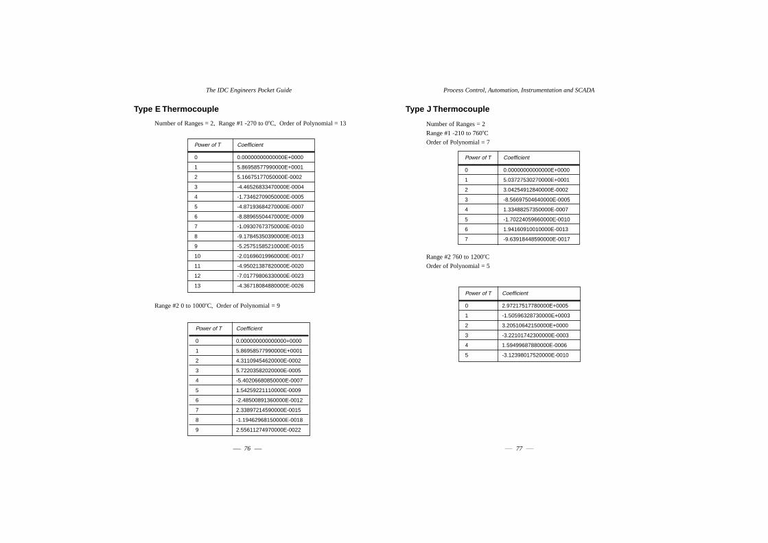
The IDC Engineers Pocket Guide
76
Process Control, Automation, Instrumentation and SCADA
77
Type J Thermocouple
Number of Ranges = 2
Range #1 -210 to 760oC
Order of Polynomial = 7
Range #2 760 to 1200oC
Order of Polynomial = 5
Power of T Coefficient
0 0.00000000000000E+0000
1 5.03727530270000E+0001
2 3.04254912840000E-0002
3 -8.56697504640000E-0005
4 1.33488257350000E-0007
5 -1.70224059660000E-0010
6 1.94160910010000E-0013
7 -9.63918448590000E-0017
Power of T Coefficient
0 2.97217517780000E+0005
1 -1.50596328730000E+0003
2 3.20510642150000E+0000
3 -3.22101742300000E-0003
4 1.59499687880000E-0006
5 -3.12398017520000E-0010
Type E Thermocouple
Number of Ranges = 2, Range #1 -270 to 0oC, Order of Polynomial = 13
Range #2 0 to 1000oC, Order of Polynomial = 9
Power of T Coefficient
0 0.00000000000000E+0000
1 5.86958577990000E+0001
2 5.16675177050000E-0002
3 -4.46526833470000E-0004
4 -1.73462709050000E-0005
5 -4.87193684270000E-0007
6 -8.88965504470000E-0009
7 -1.09307673750000E-0010
8 -9.17845350390000E-0013
9 -5.25751585210000E-0015
10 -2.01696019960000E-0017
11 -4.95021387820000E-0020
12 -7.01779806330000E-0023
13 -4.36718084880000E-0026
Power of T Coefficient
0 0.000000000000000+0000
1 5.86958577990000E+0001
2 4.31109454620000E-0002
3 5.72203582020000E-0005
4 -5.40206680850000E-0007
5 1.54259221110000E-0009
6 -2.48500891360000E-0012
7 2.33897214590000E-0015
8 -1.19462968150000E-0018
9 2.55611274970000E-0022

Process Control, Automation, Instrumentation and SCADA
79
Type K Thermocouple
Number of Ranges = 2
Range #1 -270 to 0oC
Order of Polynomial = 10
Range #2 0 to 1372oC
Order of Polynomial = 8
Power of T Coefficient
0 0.00000000000000E+0000
1 3.94754331390000E+0001
2 2.74652511380000E-0002
3 -1.65654067160000E-0004
4 -1.51909123920000E-0006
5 -2.45816709240000E-0008
6 -2.47579178160000E-0010
7 -1.55852761730000E-0012
8 -5.97299212550000E-0015
9 -1.26888012160000E-0017
10 -1.13827973740000E-0020
Power of T Coefficient
0 -1.85330632730000E+0001
1 3.89183446120000E+0001
2 1.66451543560000E-0002
3 -7.87023744480000E-0005
4 2.28357855570000E-0007
5 -3.57002312580000E-0010
6 2.99329091360000E-0013
7 -1.28498487980000E-0016
8 2.22399743360000E-0020
The IDC Engineers Pocket Guide
78
Type JP Thermocouple
Number of Ranges = 1
Range #1 -210 to 760oC
Order of Polynomial = 7
Type JN Thermocouple
Number of Ranges = 1
Range #1 -210 to 760oC
Order of Polynomial = 7
Power of T Coefficient
0 0.00000000000000E+0000
1 3.24624328230000E+0001
2 2.57607151740000E-0002
3 -1.44972898550000E-0005
4 -2.33915030000000E-0010
5 -1.97664327600000E-0011
6 4.07707598990000E-0014
7 -2.11338974270000E-0017
Power of T Coefficient
0 0.00000000000000E+0000
1 1.79103202040000E+0001
2 4.66477610970000E-0003
3 -7.11724606090000E-0005
4 1.33722172380000E-0007
5 -1.50457626900000E-0010
6 1.53390150110000E-0013
7 7.52579474320000E-0017

Process Control, Automation, Instrumentation and SCADA
81
Type KN Thermocouple
Number of Ranges = 2
Range #1 -270 to 0oC
Order of Polynomial = 12
Range #2 0 to 1372oC
Order of Polynomial = 8
Power of T Coefficient
0 0.00000000000000E+0000
1 1.36397230060000E+0001
2 2.63104723000000E-0004
3 2.17802309280000E-0004
4 1.53219743930000E-0005
5 4.21959974230000E-0007
6 6.76856722290000E-0009
7 6.85556478860000E-0011
8 4.51139628800000E-0013
9 1.92400134930000E-0015
10 5.12342695880000E-0018
11 7.72685151860000E-0021
12 5.02907385360000E-0024
Power of T Coefficient
0 -1.85330632730000E+0001
1 1.30826344790000E+0001
2 -9.47699793200000E-0003
3 -4.51409050693000E-000
4 2.12456454550000E-0007
5 -3.56398563240000E-0010
6 3.00537841510000E-0013
7 -1.28498487980000E-0016
8 2.22399743360000E-0020
The IDC Engineers Pocket Guide
80
Type KP Thermocouple
Number of Ranges = 2
Range #1 -270 to 0oC
Order of Polynomial = 12
Range #2 0 to 1372oC
Order of Polynomial = 6
Power of T Coefficient
0 0.00000000000000E+0000
1 2.58357101330000E+0001
2 2.72021464150000E-0002
3 -3.83456376440000E-0004
4 -1.68410656320000E-0005
5 -4.46541645150000E-0007
6 -7.01614640110000E-0009
7 -7.01141755030000E-0011
8 -4.57112620930000E-0013
9 -1.93669015050000E-0015
10 -5.13480975620000E-0018
11 -7.72685151860000E-0021
12 -5.02907385360000E-0024
Power of T Coefficient
0 0.00000000000000E+0000
1 2.58357101330000E+0001
2 2.61221522880000E-0002
3 -3.35533237550000E-0005
4 1.59014010170000E-0008
5 -6.03749339390000E-0013
6 -1.20875015000000E-0015

Process Control, Automation, Instrumentation and SCADA
83
Range #4 1665 to 1767.6oC
Order of Polynomial = 3
Type S Thermocouple
Number of Ranges = 4
Range #1 -50 to 630.74oC
Order of Polynomial = 6
Range #2 630.74 to 1064.43oC
Order of Polynomial = 2
Power of T Coefficient
0 9.54455599100000E+0004
1 -1.66425003590000E+0002
2 1.09757432390000E-0001
3 -2.22892169800000E-0005
Power of T Coefficient
0 0.00000000000000E+0000
1 5.39957823460000E-0002
2 1.25197000000000E-0002
3 -2.25448217997000E-0005
4 2.84521649490000E-0008
5 -2.24405845440000E-0011
6 8.50541669360000E-0015
Power of T Coefficient
0 -2.98244816150000E+0002
1 8.23755282210000E+0000
2 1.64539099420000E-0003
The IDC Engineers Pocket Guide
82
Type R Thermocouple
Number of Ranges = 4
Range #1 -50 to 630.74oC
Order of Polynomial = 7
Range #2 630.74 to 1064.43oC
Order of Polynomial = 3
Range #3 1064.43 to 1665oC
Order of Polynomial = 3
Power of T Coefficient
0 0.00000000000000E+0000
1 5.28913950590000E+0000
2 1.39111099470000E-0002
3 -2.40052384300000E-0005
4 3.62014105950000E-0008
5 -4.46450193600000E-0011
6 3.84976918650000E-0014
7 -1.53726415590000E-0017
Power of T Coefficient
0 -2.64180070250000E+0002
1 8.04686807470000E+0000
2 2.98922937230000E-0003
3 -2.68760586170000E-0007
Power of T Coefficient
0 1.49017027020000E+0003
1 2.86398675520000E+0000
2 8.08236311890000E-0003
3 -1.93384776380000E-0006

Process Control, Automation, Instrumentation and SCADA
85
Type T Thermocouple
Number of Ranges = 2, Range #1 -270 to 0oC, Order of Polynomial = 14
Range #2 0 to 400oC
Order of Polynomial = 8
Power of T Coefficient
0 0.00000000000000E+0000
1 3.87407738400000E+0001
2 4.41239324820000E-0002
3 1.14052384980000E-0004
4 1.99744065680000E-0005
5 9.04454011870000E-0007
6 2.27660185040000E-0008
7 3.62474093800000E-0010
8 3.86489242010000E-0012
9 2.82986785190000E-0014
10 1.42813833490000E-0016
11 4.88332543640000E-0019
12 1.08034746830000E-0021
13 1.39492910260000E-0024
14 7.97958931560000E-0028
Power of T Coefficient
0 0.00000000000000E+0000
1 3.87407738400000E+0001
2 3.31901980920000E-0002
3 2.07141836450000E-0004
4 -2.19458348230000E-0006
5 1.10319005500000E-0008
6 -3.09275818980000E-0011
7 4.56533371650000E-0014
8 -2.76168780400000E-0017
The IDC Engineers Pocket Guide
84
Range #3 1064.43 to 1665oC
Order of Polynomial = 3
Range #4 1665 to 1767.6oC
Order of Polynomial = 3
Power of T Coefficient
0 1.27662921750000E+0003
1 3.49709080410000E+0000
2 6.38246486660000-0003
3 -1.57224245990000E-0006
Power of T Coefficient
0 9.78466553610000E+0004
1 -1.70502956320000E+0002
2 1.10886997680000E-0003
3 -2.24940708490000E-0005
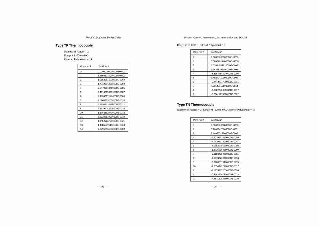
Process Control, Automation, Instrumentation and SCADA
87
Range #0 to 400oC, Order of Polynomial = 9
Type TN ThermocoupleNumber of Ranges = 2, Range #1 -270 to 0oC, Order of Polynomial = 13
Power of T Coefficient
0 0.00000000000000E+0000
1 5.88062617400000E+0000
2 1.62014049810000E-0002
3 1.16368154490000E-0004
4 -1.63847540040000E-0006
5 9.48870459000000E-0009
6 -2.84437817350000E-0011
7 4.33143650190000E-0014
8 -2.64222483580000E-0017
9 -2.55611274970000E-0022
Power of T Coefficient
0 0.00000000000000E+0000
1 3.28601476660000E+0001
2 2.44653712900000E-0002
3 -6.30704570300000E-0005
4 -5.05205273000000E-0007
5 -4.06520391200000E-0008
6 -1.87350864360000E-0009
7 -3.91934982500000E-0011
8 -4.60732739460000E-0013
9 -3.32082570160000E-0015
10 -1.50347922400000E-0017
11 -4.17752872630000E-0020
12 -6.51489067700000E-0023
13 -4.36718084880000E-0026
The IDC Engineers Pocket Guide
86
Type TP Thermocouple
Number of Ranges = 2
Range # 1 -270 to 0oC
Order of Polynomial = 14
Power of T Coefficient
0 0.00000000000000E+0000
1 5.88026174000000E+0000
2 1.96585611920000E-0002
3 1.77122842010000E-0004
4 2.04796118410000E-0005
5 9.45106050990000E-0007
6 2.46395271480000E-0008
7 4.01667592050000E-0010
8 4.32562514960000E-0012
9 3.16195042210000E-0014
10 1.57848625730000E-0016
11 5.30107830900000E-0019
12 1.14549637510000E-0021
13 1.43860091110000E-0024
14 7.97958931560000E-0028
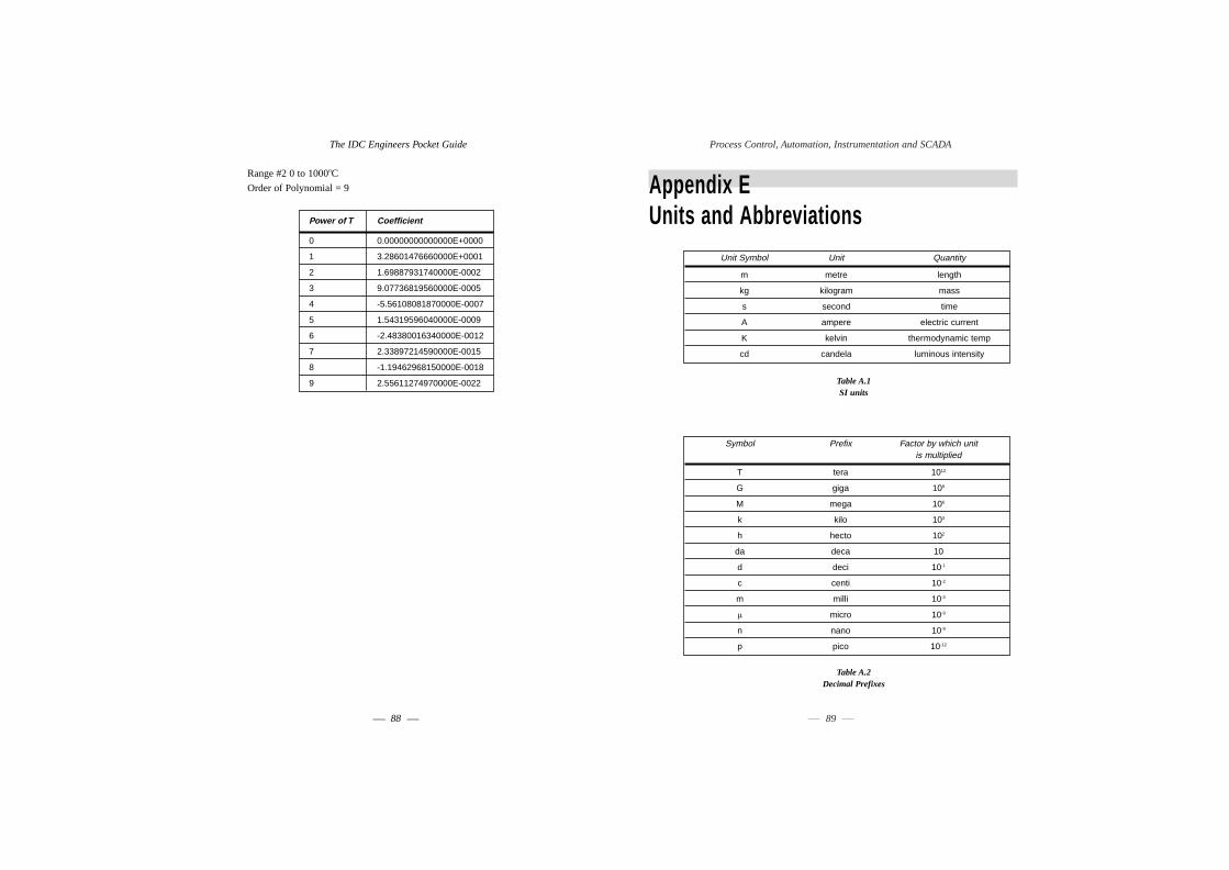
Process Control, Automation, Instrumentation and SCADA
89
Appendix EUnits and Abbreviations
Table A.1SI units
Table A.2Decimal Prefixes
Symbol Prefix Factor by which unit is multiplied
T tera 1012
G giga 109
M mega 106
k kilo 103
h hecto 102
da deca 10
d deci 10-1
c centi 10-2
m milli 10-3
µ micro 10-9
n nano 10-9
p pico 10-12
Unit Symbol Unit Quantity
m metre length
kg kilogram mass
s second time
A ampere electric current
K kelvin thermodynamic temp
cd candela luminous intensity
The IDC Engineers Pocket Guide
88
Range #2 0 to 1000oC
Order of Polynomial = 9
Power of T Coefficient
0 0.00000000000000E+0000
1 3.28601476660000E+0001
2 1.69887931740000E-0002
3 9.07736819560000E-0005
4 -5.56108081870000E-0007
5 1.54319596040000E-0009
6 -2.48380016340000E-0012
7 2.33897214590000E-0015
8 -1.19462968150000E-0018
9 2.55611274970000E-0022

Process Control, Automation, Instrumentation and SCADA
91
Table A.6 Physical Constants
Name Symbol Equivalent
Avogadro's number N 6.023 x 1026 /(kg mol)
Bohr magneton B 9.27 x 10⁻²⁴ A m 252
Boltzmann's constant k 1.380 x 10⁻²³ J/k
Stefan-Boltzmann constant d 5.67 x 10⁻⁸ W/(m2K4)
Characteristic impedance of free space Zo (µo/Eo)1/2=120πΩ
Electron volt eV 1.602 x 10⁻¹⁹J
Electron charge e 1.602 x 10⁻¹⁹C
Electronic rest mass me 9.109 x 10⁻³¹kg
Electronic charge to mass ratio e/me 1.759 x 10¹¹ C/kg
Faraday constant F 9.65 x 10⁷ C/(kg mol)
Permeability of free space µo 4π x 10-7 H/m
Permittivity of free space Eo 8.85 x 10⁻¹² F/m
Planck's constant h 6.626 x 10⁻³⁴ J s
Proton mass mp 1.672 x 10⁻²⁷ kg
Proton to electron mass ratio mp/me 1835.6
Standard gravitational acceleration g 9.80665 m/s2
9.80665 N/kg
Universal constant of gravitation G 6.67 x 10⁻¹¹ N m2/kg2
Universal gas constant Ro 8.314 kJ/(kg mol K)
Velocity of light in vacuo C 2.9979 x 10⁸ m/s
Volume of 1 kg mol of ideal gas at - 22.41 m3
1 atm & 0oC
Temperature 0C 5/9(0F - 32)
Temperature K 5/9(0F + 459.67)5/90R
0C + 273.15
The IDC Engineers Pocket Guide
90
Table A.3 Supplementary and Derived Units
Table A.4 Supplementary and Derived Unit (electrical)
Table A.5 Supplementary and Derived Units (magnetic)
Quantity Magnetic unit Symbol Derived unit
magnetic flux weber Wb V s = Nm/A
inductance henry H V s/A = Nm/A2
magnetic field strength - A/m -
magnetic flux density tesla T Wb/m2 = (N)/(Am)
Quantity Electrical unit Symbol Derived unit
potential volt V W/A
resistance ohm Ω V/A
charge coulomb C A s
capacitance farad F A s/V
electric field strength - V/m -
electric flux density - C/m2 -
Quantity Unit Symbol Equivalent
plane angle radian rad -
force newton N kg m/s2
work, energy heat joule J N m
power watt W J/s
frequency hertz Hz s-1
viscosity: kinematic - m2/s 10 c St (Centistoke)
dynamic - Ns/m2 or Pa s 103 cP (Centipoise)
pressure - Pa or N/m2 pascal, Pa

Process Control, Automation, Instrumentation and SCADA
93
Symbol Description SI Unit
Q Volumetric flow rate m3s-1
Q Charge C
R Resistance Ω
s Fractional slip -
t Time s
T Time Factor -
T Torque Nm
T Temperature (absolute) K
∆T Temperature difference oC
u Velocity ms-1
v Velocity ms-1
V Voltage V
V Volume m3
x Distance (variables as in dx) m
Z Number of armature conductors -
Z Impedance Ω
a Coefficient of volumetric expansion Hm/(mK)
a Resistance coefficient Ω K-1
b Coefficient of volumetric expansion K-1
eo Permittivity of free space Fm-1
eo Permittivity-relative -
mo Permeability of free space Hm-1
mr Permeability-relative -
ro Resistivity Ω m3
r Density kgm3
s Stefan-Boltzmann constant Wm-2K-4
φ Angle radians
F Magnetic flux, flux per pole Wb
w Angular Velocity rad.s-1
wn Natural frequency rad.s-1
wo Natural frequency rad.s-1
wd Damped natural frequency rad.s-1
The IDC Engineers Pocket Guide
92
Appendix FCommonly used FormulaeSymbols used in formulae
The symbols described in the following table are used in the formulae shown in
the next section
Symbol Description SI Unit
a Velocity of sound ms-1
a Acceleration ms-2
A Area m2
c Velocity of light ms-1
C Capacitance F
D Diameter m
E Young's modulus Nm-2
∆E Energy difference J
f Frequency Hz
F Force N
H Magnetising force magnetic field strength Am-1
I Current A
I Moment of inertia kgm2
k Radius of gyration m
kp Pitch factor of winding -
l Length m
l Length of conductor m
L Inductance H
m Mass kg
M Momentum Kg.m.s-1
n Speed of rotation rpm
N Number of turns -
p Number of pole pairs -

Process Control, Automation, Instrumentation and SCADA
95
Resistors in parallel:
Inductance
for LR circuit decay, stored energy is calculated as follows:
Capacitance
The IDC Engineers Pocket Guide
94
Formulae
Ohm's Law (DC version)
V = IR
Ohm's Law (AC version)
V = I . Z
Kirchhoff's Law
Power
Resistance
Resistors in series:
R = R1 + R2 + R3 + ...

Process Control, Automation, Instrumentation and SCADA
97
Electrostatics
Electromagnetism
For a solenoid:
The IDC Engineers Pocket Guide
96
For n parallel plates:
For RC circuit discharge:
Stored energy:
For capacitors in series:
For capacitors in parallel:

Process Control, Automation, Instrumentation and SCADA
99
At resonance the following relationship holds true:
The Q factor can be calculated as follows:
Sound
Note that decibels are not units as such but a ratio of voltages, currents and power,
for example:
where: P1, P2 are the power levels:
For differing input and output impedances the following formula is appropriate:
Where V1, V2 are the voltages
Z1, Z2 are the impedances.
The IDC Engineers Pocket Guide
98
Magnetism
For a magnetic circuit:
Stored energy density:
AC Circuits
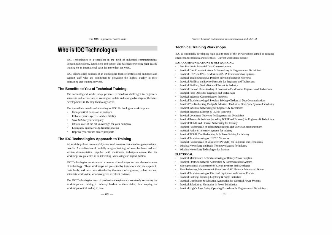
Process Control, Automation, Instrumentation and SCADA
101
Technical Training Workshops
IDC is continually developing high quality state of the art workshops aimed at assisting
engineers, technicians and scientists. Current workshops include:
DATA COMMUNICATIONS & NETWORKING• Best Practice in Industrial Data Communications• Practical Data Communications & Networking for Engineers and Technicians• Practical DNP3, 60870.5 & Modern SCADA Communication Systems• Practical Troubleshooting & Problem Solving of Ethernet Networks• Practical FieldBus and Device Networks for Engineers and Technicians• Practical Fieldbus, DeviceNet and Ethernet for Industry• Practical Use and Understanding of Foundation FieldBus for Engineers and Technicians• Practical Fibre Optics for Engineers and Technicians• Practical Industrial Communication Protocols• Practical Troubleshooting & Problem Solving of Industrial Data Communications• Practical Troubleshooting, Design & Selection of Industrial Fibre Optic Systems for Industry• Practical Industrial Networking for Engineers & Technicians• Practical Industrial Ethernet & TCP/IP Networks• Practical Local Area Networks for Engineers and Technicians• Practical Routers & Switches (including TCP/IP and Ethernet) for Engineers & Technicians• Practical TCP/IP and Ethernet Networking for Industry• Practical Fundamentals of Telecommunications and Wireless Communications• Practical Radio & Telemetry Systems for Industry• Practical TCP/IP Troubleshooting & Problem Solving for Industry• Practical Troubleshooting of TCP/IP Networks• Practical Fundamentals of Voice over IP (VOIP) for Engineers and Technicians• Wireless Networking and Radio Telemetry Systems for Industry• Wireless Networking Technologies for Industry
ELECTRICAL• Practical Maintenance & Troubleshooting of Battery Power Supplies• Practical Electrical Network Automation & Communication Systems• Safe Operation & Maintenance of Circuit Breakers and Switchgear• Troubleshooting, Maintenance & Protection of AC Electrical Motors and Drives• Practical Troubleshooting of Electrical Equipment and Control Circuits• Practical Earthing, Bonding, Lightning & Surge Protection• Practical Distribution & Substation Automation for Electrical Power Systems• Practical Solutions to Harmonics in Power Distribution• Practical High Voltage Safety Operating Procedures for Engineers and Technicians
The IDC Engineers Pocket Guide
100
Who is IDC TechnologiesIDC Technologies is a specialist in the field of industrial communications,
telecommunications, automation and control and has been providing high quality
training on an international basis for more than ten years.
IDC Technologies consists of an enthusiastic team of professional engineers and
support staff who are committed to providing the highest quality in their
consulting and training services.
The Benefits to You of Technical TrainingThe technological world today presents tremendous challenges to engineers,
scientists and technicians in keeping up to date and taking advantage of the latest
developments in the key technology areas.
The immediate benefits of attending an IDC Technologies workshop are:
• Gain practical hands-on experience
• Enhance your expertise and credibility
• Save $$$ for your company
• Obtain state of the art knowledge for your company
• Learn new approaches to troubleshooting
• Improve your future career prospects
The IDC Technologies Approach to TrainingAll workshops have been carefully structured to ensure that attendees gain maximum
benefits. A combination of carefully designed training software, hardware and well
written documentation, together with multimedia techniques ensure that the
workshops are presented in an interesting, stimulating and logical fashion.
IDC Technologies has structured a number of workshops to cover the major areas
of technology. These workshops are presented by instructors who are experts in
their fields, and have been attended by thousands of engineers, technicians and
scientists world-wide, who have given excellent reviews.
The IDC Technologies team of professional engineers is constantly reviewing the
workshops and talking to industry leaders in these fields, thus keeping the
workshops topical and up to date.

Process Control, Automation, Instrumentation and SCADA
103
• Practical Fundamentals of OPC (OLE for Process Control)• Practical Process Control for Engineers and Technicians• Practical Process Control & Tuning of Industrial Control Loops• Practical Industrial Programming using 61131-3 for PLCs• Practical SCADA & Telemetry Systems for Industry• Practical Shutdown & Turnaround Management for Engineers and Managers• Practical Safety Instrumentation and Shut-down Systems for Industry• Practical Fundamentals of E-Manufacturing, MES and Supply Chain Management• Practical Safety Instrumentation & Emergency Shutdown Systems for Process Industries• Control Valve Sizing, Selection and Maintenance
MECHANICAL ENGINEERING• Practical Fundamentals of Heating, Ventilation & Airconditioning (HVAC) • Practical Boiler Plant Operation and Management for Engineers and Technicians• Practical Bulk Materials Handling (Conveyors, Bins, Hoppers & Feeders)• Practical Pumps and Compressors: Control, Operation, Maintenance & Troubleshooting• Practical Cleanroom Technology and Facilities for Engineers and Technicians• Gas Turbines: Troubleshooting, Maintenance & Inspection• Practical Hydraulic Systems: Operation and Troubleshooting• Practical Lubrication Engineering for Engineers and Technicians• Practical Safe Lifting Practice and Maintenance• Practical Mechanical Drives (Belts, Chains etc) for Engineers & Technicians• Fundamentals of Mechanical Engineering• Practical Pneumatics: Operations and Troubleshooting for Engineers & Technicians• Practical Centrifugal Pumps - Optimising Performance• Practical Machinery and Automation Safety for Industry• Practical Machinery Vibration Analysis and Predictive Maintenance
PROJECT & FINANCIAL MANAGEMENT• Practical Financial Fundamentals and Project Investment Decision Making• How to Manage Consultants• Marketing for Engineers and Technical Personnel• Practical Project Management for Engineers and Technicians• Practical Specification and Technical Writing for Engineers
CHEMICAL ENGINEERING• Practical Fundamentals of Chemical Engineering
CIVIL ENGINEERING• Hazardous Waste Management and Pollution Prevention• Structural Design for non-structural Engineers• Best Practice in Sewage and Effluent Treatment Technologies
The IDC Engineers Pocket Guide
102
• Practical Electrical Wiring Standards - National Rules for Electrical Installations -• Lightning, Surge Protection and Earthing of Electrical & Electronic Systems • Practical Power Distribution• Practical Power Quality: Problems & Solutions
ELECTRONICS• Practical Digital Signal Processing Systems for Engineers and Technicians• Practical Embedded Controllers: Troubleshooting and Design• Practical EMC and EMI Control for Engineers and Technicians• Practical Industrial Electronics for Engineers and Technicians• Practical Image Processing and Applications• Power Electronics and Variable Speed Drives: Troubleshooting & Maintenance• Practical Shielding, EMC/EMI, Noise Reduction, Earthing and Circuit Board Layout
INFORMATION TECHNOLOGY• Practical Web-Site Development & E-Commerce Systems for Industry• Industrial Network Security for SCADA, Automation, Process Control & PLC Systems• SNMP Network Management: The Essentials• VisualBasic Programming for Industrial Automation, Process Control & SCADA Systems
INSTRUMENTATION, AUTOMATION & PROCESS CONTROL• Practical Analytical Instrumentation in On-Line Applications• Practical Alarm Systems Management for Engineers and Technicians• Practical Programmable Logic Controller's (PLCs) for Automation and Process Control• Practical Batch Management & Control (Including S88) for Industry• Practical Boiler Control and Instrumentation for Engineers and Technicians• Practical Programming for Industrial Control - using ( IEC 1131-3 and OPC )• Practical Distributed Control Systems (DCS) for Engineers & Technicians• Practical Data Acquisition using Personal Computers and Standalone Systems• Best Practice in Process, Electrical & Instrumentation Drawings and Documentation• Practical Troubleshooting of Data Acquisition & SCADA Systems• Practical Industrial Flow Measurement for Engineers and Technicians• Practical Hazops, Trips and Alarms• Practical Hazardous Areas for Engineers and Technicians• A Practical Mini MBA in Instrumentation and Automation• Practical Instrumentation for Automation and Process Control• Practical Intrinsic Safety for Engineers and Technicians• Practical Tuning of Industrial Control Loops• Practical Motion Control for Engineers and Technicians• Practical SCADA and Automation for Managers, Sales and Admininistration• Practical Automation, SCADA and Communication Systems: A Primer for Managers

Process Control, Automation, Instrumentation and SCADA
105
The IDC Engineers Pocket Guide
104
Comprehensive Training MaterialsWorkshop Documentation
All IDC Technologies workshops are fully documented with complete reference
materials including comprehensive manuals and practical reference guides.
Software
Relevant software is supplied with most workshops. The software consists of
demonstration programs which illustrate the basic theory as well as the more
difficult concepts of the workshop.
Hands-On Approach to Training
IDC Technologies engineers have developed the workshops based on the practical
consulting expertise that has been built up over the years in various specialist
areas. The objective of training today is to gain knowledge and experience in the
latest developments in technology through cost effective methods.
The investment in training made by companies and individuals is growing each
year as the need to keep topical and up to date in the industry which they are
operating is recognized. As a result, IDC Technologies instructors place particular
emphasis on the practical, hands-on aspect of the workshops presented.
On-site Workshops
In addition to the external workshops which IDC Technologies presents on a
world-wide basis, all IDC Technologies workshops are also available for on-site
(in-house) presentation at our clients premises.
On-site training is a cost effective method of training for companies with many
delegates to train in a particular area. Organizations can save valuable training $$$
by holding workshops on-site, where costs are significantly less. Other benefits
are IDC Technologies ability to focus on particular systems and equipment so that
attendees obtain only the greatest benefits from the training.
All on-site workshops are tailored to meet with clients training requirements and
workshops can be presented at beginners, intermediate or advanced levels based
on the knowledge and experience of delegates in attendance. Specific areas of
interest to the client can also be covered in more detail.
Our external workshops are planned well in advance and you should contact us as
early as possible if you require on-site/customized training. While we will always
endeavor to meet your timetable preferences, two to three months notice is
preferable in order to successfully fulfil your requirements.
Please don’t hesitate to contact us if you would like to discuss your training needs.
Customized Training
In addition to standard on-site training, IDC Technologies specializes in
customized workshops to meet client training specifications. IDC Technologies
has the necessary engineering and training expertise and resources to work closely
with clients in preparing and presenting specialized workshops.
These workshops may comprise a combination of all IDC Technologies
workshops along with additional topics and subjects that are required. The benefits
to companies in using training is reflected in the increased efficiency of their
operations and equipment.
Training Contracts
IDC Technologies also specializes in establishing training contracts with
companies who require ongoing training for their employees. These contracts can
be established over a given period of time and special fees are negotiated with
clients based on their requirements. Where possible IDC Technologies will also
adapt workshops to satisfy your training budget.
References from various international companies to whom IDC Technologies is
contracted to provide on-going technical training are available on request.

Process Control, Automation, Instrumentation and SCADA
107
Nutrients • Contact Energy • Ericcson • Fisher & Paykel • GEC Alsthom • James Hardie• Methanex • Natural Gas • NZ Water and Waste Assoc • Norske Skog • NZ AluminiumSmelters • NZ Refining Co • Pan Pac Forest Products • Powerco • Rockwell • RotoruaDistrict Council • Royal New Zealand Navy • The University of Auckland
SingaporeActivemedia Innovation Pte Ltd • Flotech Controls • Land Transport Authority •Ngee Ann Polytechnic • Power Seraya Ltd • Westinghouse • Yokogawa Singapore
South AfricaAnglo American • Bateman Metals • Caltex Refineries • Chevron • Columbus Stainless• De Beers • Durban Metro • Eastern Cape Tech • Eskom • Grintek Ewation • HighveldSteel • Illovo Sugar • Impala Platinums • Iscor • IST• Joy Mining • Lever Ponds • MetsoAutomation • Middleburg Ferrochrome • Mintek • Mondi Kraft • Mossgas • NamaquaSands • Nestle • Orbicom • Rand Water Board • Richards Bay Minerals • SA Navy •SABC • Saldanha Steel • Sappi • Sasol • Spoornet • Umgeni Water • Western Platinum• Witwatersrand Technikon • Yelland Controls
United Kingdom24 Seven • ABB Automation Ltd • Aer Rianta • Air Products • Allied Colloids •Allied Distillers • Alstom • BAE Systems • Bechtel • BNFL - Magnox Generation• BP Chemicals • British American Tobacco • British Energy • British Gas • BritishSteel • Cegelec • Conoco • Corus Group Plc • Energy Logistics • Eurotherm •Eurotunnel • Evesham Micros • Exult Ltd • Fisher Rosemount • GEC Meters •Glaxo Smith Kline • Glaxo Wellcome • Great Yarmouth Power • Halliburton •Honeywell • ICI Nobel Enterprises • ICS Triplex • Inmarsat Ltd • Instem Limited• Johnson Matthey • Kodak • Kvaerner Energy • Lever Fabrige • Lindsay OilRefinery • Lloyds • Logica • Lucas Aerospace • Mobil Oil • NEC • Nissan •Northern Lighthouse Board • OKI Europe Ltd • Phillips Petroleum • Powergen •Qinetiq • Rail Track Systems • Rig Tech • Roberts & Partners • Rolls Royce •Rover Group • Rugby Cement • Scottish Courage • Scottish Hydro Electric Plc •Scottish Power • Shell Chemicals • Shotton Paper Plc • Siemens • StrathclydeWater • Thames Water • Toyota • Transco • Trend Control Systems Ltd • UKAEA• United Kingdom Paper • Yarrow Shipbuilders • Yorkshire Electric
USAAlcatel • Allen Bradley • Astra Zeneca Pharmaceuticals • Avista Corporation • Boeing• Chevron • City of Detroit • Daishowa Paper Mill • Degussa Corporation • Dept ofEnergy • Detroit Water • Exxon Mobil Chemical Company • FMC Corporation •General Monitors • Honeywell • Hughes Aircraft • ISA • K-Tron Institute • MckeeFoods • Milltronics • NASA • Pepperl Fuchs • Phelps Dodge • Philip Morris • SanDiego County Water Authority • San Francisco Water Department • Santa Clara ValleyWater • Securities Industry Automation Corp • Siemens Power • Siemens Westinghouse• Toyota • Tucson Electric • United Technologies Corp (UTC) • Valtek • WashingtonWater Power • Wisconsin Power • Zeneca
Some of the thousands of Companies world-wide thathave supported and benefited from IDC Technologiesworkshops are:
AustraliaAlcoa • Alinta Gas • Ampol Refineries • Ansto • Australian Communications Authority• Australian Geological Society • BHP Billiton • BOC Gases • Boeing Constructors Inc• Brisbane City Council • British Aerospace Australia • Ci Technologies • CivilAviation Authority • Comalco Aluminium • CSIRO • Delta Electricity • Dept ofDefence • Dept of Transport and Works • DSTO • Duke Energy International •Emerson Process Management • Energex • ERG Group • Ergon Energy • ETSA •Gippsland Water • Gladstone Tafe College • Gosford City Council • Great SouthernEnergy • Hamersley Iron • Hewlett Packard • Holden Ltd • Honeywell • I&E SystemsPty Ltd • Integral Energy • Metro Brick • Millenium Chemicals • Mt Isa Mines •Murdoch University • Nabalco • NEC • Nilson Electric • Normandy Gold • Nu-LecIndustries • Parker Hannafin • Pharmacia & Upjohn • Power & Water Authority NT•Powercor • Powerlink • Prospect Electricity • Queensland Alumina • Raaf • Raytheon• RGC Mineral Sands • Robe River Iron Associates • Royal Darwin Hospital • SantosLtd • Schneider Electric • Shell • Snowy Mountain Hydro • SPC Fruit • Stanwell PowerStation • Telstra • Tiwest • Uncle Bens • Vision • Wesfarmers CSBP • Western Power• Westrail • WMC • Woodside • Worsley Alumina • Wyong Shire • Yokogawa Australia
BotswanaDe Beers - Jwaneng Mine • De Beers - Orapa Mine
CanadaAircom Industries (76) Ltd • Atco Electric • BC Gas • BC Hydro • City of Ottawa •City of Saskatoon • Conoco • Dept of National Defence • Enbridge Pipelines • Enmax• Ford Electronics • GE Energy Services • General Motors • Guillevin Automation •Husky Oil • Imperial Oil • INCO Ltd • Labrador Hydro • Manitoba Hydro • ManitobaLotteries Corp • Memorial University of New Foundland • New Brunswick Power •Nova Chemicals • Nxtphase Corporation • Ontario Hydro • Ottawa Hydro • PetroCanada • Power Measurement Ltd • Saskatchewan Power • Spartan Controls • Stora •Suncor Energy • Syncrude • Telus • Trans Canada Pipelines • Trojan Technologies •Wascana Energy • Weyerhauser
IrelandBayer Diagnostics • ESB Distribution • Intel • Irish Cement • Jannsen Pharmaceuticals• Microsol Limited • Pfizer • Pilz Ireland • Proscon Engineering
NambiaNamibian Broadcasting Corporation • Nampower • Namwater
New ZealandACI Packaging • Anchor Products • Auckland Regional Council • Ballance Agri
The IDC Engineers Pocket Guide
106
Process Control, Automation, Instrumentation and SCADA
109
Singapore
100 Eu Tong Sen Street, #04-11 Pearl's Centre, 059812
Tel: (65) 6224 6298 Fax: (65) 6224 7922
South Africa
PO Box 785640, Sandton 2146, Johannesburg
Tel: 0800 114 160 Fax: (011) 883 0610
UK
46 Central Road, Worcester Park, Surrey KT4 8HY
Tel: (020) 8335 4014 Fax: (020) 8335 4120
USA
7101 Highway 71 West #200, Austin TX 78735
Tel: 1800 324 4244 Fax: 1800 434 4045
Email: [email protected] site: www.idc-online.com
IDC Technologies - Worldwide Offices
For further information about current or future workshops please contact your
local office:
Australia - West Coast Office
PO Box 1093, West Perth WA 6872
Tel: (08) 9321 1702 Fax: (08) 9321 2891
Australia - East Coast Office
PO Box 1750, North Sydney NSW 2059
Tel: (02) 9957 2706 Fax: (02) 9955 4468
Canada
402-814 Richards Street, Vancouver BC V6B 3A7
Tel: 1800 324 4244 Fax: 1800 434 4045
Ireland
PO Box 8069, Shankill, Co Dublin
Tel: (01) 473 3190 Fax: (01) 473 3191
New Zealand
PO Box 76-142, Manukau City Auckland
Tel: (09) 263 4759 Fax: (09) 262 2304
The IDC Engineers Pocket Guide
108

Notes
The IDC Engineers Pocket Guide
110