Embed Size (px)
Citation preview

Photomicrosensor with Cable (Non-light-modulated)
Slot-type Photomicrosensor (Non-light-modulated)
Slot-type Photomicrosensor with Connector (Light-modulated)
Slot-type Photomicrosensor with Cable
Broad Slot-type Photomicrosensor
Long-distance Through-beam Photomicrosensor
Photomicrosensor with Amplifier and Cable
Slot-type Reflective Photomicrosensor
Light Convergent Reflective Photomicrosensor
Reflective Photomicrosensor with Sensitivity Adjuster (Non-light-modulated)
Retroreflective Photomicrosensor with Lens
Pipe-mounting Liquid Level Photomicrosensor with Built-in Amplifier
Wafer-carrier Mounting Photomicrosensors
Pho
tom
icro
sen
sors
DA
TA B
OO
K
PhotomicrosensorData Book

Sensing Guide 3
Application Examples 10
Definition of Terms 24
Interpreting Engineering Data 25
General Precautions 27
Slot type Non-modulated light
Models with connectors EE-SX97 33
Ultra-compact, pre-wired models EE-SX91 41
Miniature, slim models EE-SX77/87 49
General-purpose models with connectors EE-SX47/67 55
Modulated light
Models with connectors EE-SPX74/84 65
Pre-wired models EE-SPX-W 71
Models with long sensing distance EE-SPX303N/403N 75
Through-beam
Modulated light
Models with long sensing distance EE-SPW311/411 79
Amplifier relay models EE-SPW321/421 83
Reflective (with groove)
Modulated light
Models with connectors EE-SPX301/401/EE-SPY30/40 87
Convergent reflective
Modulated light
Models with connectorsEE-SPY31/41 93
Diffuse-reflective
Non-modulated light
Models with sensitivity adjusterEE-SY671/672 97
Retro-reflective
Modulated light
Models with lens and connectorsEE-SPZ-A 103
Application Liquid level Models with pipe mounting EE-SPX613 107
Wafer-carrier mounting detection
Reflective models (modulated light) EE-SPY801/802 111
Pushbutton-type models EE-SA701/801 115
Peripheraldevices
Accessories120

3
Sensing Guide
PhotomicrosensorsClassified According to Product ModelThrough-beam Type (with Slot)
AppearanceSensing distance
Opticalmodulation
Features Output configuration
Indi-cator∗
ModelPage
NPN output PNP output
Non-modulated light
Built-in connectors
Emitter/receiver window
Dark-ON/Light-ON (2 outputs)
--- EE-SX970-C1EE-SX970P-C1
33
--- EE-SX971-C1EE-SX971P-C1
--- EE-SX972-C1EE-SX972P-C1
--- EE-SX974-C1EE-SX974P-C1
--- EE-SX975-C1EE-SX975P-C1
--- EE-SX976-C1EE-SX976P-C1
--- EE-SX977-C1EE-SX977P-C1
Note: The table includes only basic specifications. Be sure to check the detailed specifications and precautions on the page given in the right column before using the Photomicrosensor.
∗ Indicates models with indicators that light red when the light is interrupted. Infrared light
22.0
7.0
26.0
5 mm(slot width)
2 mm
0.8 mm
14.7
26.2
15.5
26.013.7
22.0
21.712.8
15.5
26.016.7
22.0
13.2
22.0
13.4
13.2
22.0
13.4

4
Non-modulated light
Ultracompact pre-wired models
Emitter/receiver window
Light-ON Dark-ON (2 outputs)
---
EE-SX910-R EE-SX910P-R
41
EE-SX911-R EE-SX911P-R
EE-SX912-R EE-SX912P-R
EE-SX913-R EE-SX913P-R
EE-SX914-R EE-SX914P-R
Miniature, slim, pre-wired models
Emitter/receiver window
Dark-ON --- EE-SX770 EE-SX770P
49
EE-SX770A EE-SX770R
Light-ON --- EE-SX870 EE-SX870P
EE-SX870A EE-SX870R
Dark-ON --- EE-SX771 EE-SX771P
EE-SX771A EE-SX771R
Light-ON --- EE-SX871 EE-SX871P
EE-SX871A EE-SX871R
Dark-ON --- EE-SX772 EE-SX772P
EE-SX772A EE-SX772R
Light-ON --- EE-SX872 EE-SX872P
EE-SX872A EE-SX872R
AppearanceSensing distance
Opticalmodulation
Features Output configuration
Indi-cator∗
ModelPage
NPN output PNP output
Note: The table includes only basic specifications. Be sure to check the detailed specifications and precautions on the page given in the right column before using the Photomicrosensor.
12
24
6
5 mm(slot width)
1.2 mm
0.8 mm
12
13.4
12
12
13.4
11.7
12
13.4
11.7
16
13.4
6
31.1
4.6
18
1.45 mm
0.7 mm
21
18
13
31.1
12
19.1

5
Non-modulated light
General-purpose models with connectors
Emitter/receiver window
Dark-ON Light-ON (selectable)
--- EE-SX670 EE-SX670P
55
EE-SX670A EE-SX670R
Light-ON --- EE-SX470 EE-SX470P
Dark-ON Light-ON (selectable)
--- EE-SX671 EE-SX671P
EE-SX671A EE-SX671R
Light-ON --- EE-SX471 EE-SX471P
Dark-ON Light-ON (selectable)
--- EE-SX672 EE-SX672P
EE-SX672A EE-SX672R
Light-ON --- EE-SX472 EE-SX472P
Dark-ON Light-ON (selectable)
--- EE-SX673 EE-SX673P
EE-SX673A EE-SX673R
Light-ON --- EE-SX473 EE-SX473P
Dark-ON Light-ON (selectable)
--- EE-SX674 EE-SX674P
EE-SX674A EE-SX674R
Light-ON --- EE-SX474 EE-SX474P
Dark-ON Light-ON (selectable)
--- EE-SX675 EE-SX675P
--- EE-SX676 EE-SX676P
--- EE-SX677 EE-SX677P
AppearanceSensing distance
Opticalmodulation
Features Output configuration
Indi-cator∗
ModelPage
NPN output PNP output
Note: The table includes only basic specifications. Be sure to check the detailed specifications and precautions on the page given in the right column before using the Photomicrosensor.
6.95
25.4
22.2
5 mm(slot width)
2 mm
0.8 mm
15.5
26.2
14.5
22.2
13.426
22.2
13.412.8
13.6
21.5
15.5
22.2
16.7
26
13.4
13.2
22.2
13.2
22.2
13.4
6
Non-modulated light
General-purposepre-wired models
Emitter/receiver window
Dark-ONLight-ON(selectable)
---EE-SX670-WR
EE-SX670P-WR
55
---EE-SX671-WR
EE-SX671P-WR
---EE-SX672-WR
EE-SX672P-WR
--EE-SX673-WR
EE-SX673P-WR
---EE-SX674-WR
EE-SX674P-WR
---EE-SX675-WR
EE-SX675P-WR
---EE-SX676-WR
EE-SX676P-WR
---EE-SX677-WR
EE-SX677P-WR
v
Modulated light
Models with connectors
Emitter/receiver window
Dark-ON --- EE-SPX740 ---
65
Light-ON --- EE-SPX840 ---
Dark-ON --- EE-SPX742 ---
Light-ON --- EE-SPX842 ---
Dark-ON --- EE-SPX743 ---
Light-ON --- EE-SPX843 ---
Models with connectors
Emitter/receiver window
Dark-ON --- EE-SPX741 ---
Light-ON --- EE-SPX841 ---
AppearanceSensing distance
Opticalmodulation
Features Output configuration
Indi-cator∗
ModelPage
NPN output PNP output
Note: The table includes only basic specifications. Be sure to check the detailed specifications and precautions on the page given in the right column before using the Photomicrosensor.
26.2
25.4
6.35
5 mm(slot width)
2 mm
0.8 mm
18.7
26.2
15.5
26
26.2
13.4
26.2
13.4
12.8
25.7
13.6
15.5
13.4
16.7
26
26.2
13.4
13.2
26.2
13.4
13.2
21.2
257.4
3.6 mm(slot width)
1 mm0.5 mm
13
7
21.2
137
21.2
27.2
15.4
21.2 5 mm(slot width)
2 mm
0.8 mm

7
Classified According to Product ModelThrough-beam Type (with Slot)
Through-beam Type
AppearanceSensing distance
Opticalmodulation
Features Output configuration
Model Page
Modulated light
Models with connectorsEmitter/receiver window Dark-ON EE-SPX301
87
Light-ON EE-SPX401
Pre-wired modelsEmitter/receiver window
Dark-ON EE-SPX302-W2A
71
Light-ON EE-SPX402-W2A
Dark-ON EE-SPX304-W2A
Light-ON EE-SPX404-W2A
Dark-ON EE-SPX306-W2A
Light-ON EE-SPX406-W2A
Pre-wired modelsEmitter/receiver window Dark-ON EE-SPX305-W2A
Light-ON EE-SPX405-W2A
Dark-ON EE-SPX303N
75
Light-ON EE-SPX403N
AppearanceSensing distance
Opticalmodulation
Features Output configuration
Model Page
Modulated light
• Compact size• Bright, easy-to-see,
light (ON-state) indicator
Dark-ONEE-SPW311(set including emitter and receiver)
79
Light-ONEE-SPW411(set including emitter and receiver)
• Compact, slim profile• Excellent space efficiency
Dark-ONEE-SPW321EE-SPW321-A
83
Light-ONEE-SPW421EE-SPW421-A
Note: The table includes only basic specifications. Be sure to check the detailed specifications and precautions on the page given in the right column before using the Photomicrosensor.
Infrared light
7
26
24
3.6 mm(slot width)
1 mm0.5 mm
7
13
21.2
1 mm0.5 mm7
21.2
13
7.4
25
21.2
14.5
27.2
15.5 5 mm(slot width) 2 mm
0.8 mm
7.4
26
26 13 mm(slot width)
2.2
0.5
Infrared light
8
25.4
27
1 m
300 mm

8
Classified According to Product ModelReflective Type
Retroreflective Type
AppearanceSensing distance
Sensing method
Opticalmodulation
Features Output configuration
Model Page
Diffuse-reflective
Modulatedlight
Resistant to external light interference
Dark-ON EE-SPY301
87
Light-ON EE-SPY401
Dark-ON EE-SPY302
Light-ON EE-SPY402
Conver-gent reflec-tive
Resistant to background interference
Dark-ON EE-SPY311
93
Light-ON EE-SPY411
Dark-ON EE-SPY312
Light-ON EE-SPY412
Diffuse-reflective
Non-modulated light
Equipped with sensitivity adjuster
Dark-ON Light-ON (selectable)
EE-SY671
97
EE-SY672
Appearance Sensing distance Opticalmodulation
Features Output configuration
Model Page
Modulated light
Modulated light
Dark-ON EE-SPZ301-A
103Light-ON EE-SPZ401-A
Note: The table includes only basic specifications. Be sure to check the detailed specifications and precautions on the page given in the right column before using the Photomicrosensor.
Infrared light
20
267
5 mm
20
267
22.8
26
8
Horizontal model
2 to 5 mm
22.8
26
8
Vertical model
25
25.4
7
Horizontal model
1 to 5 mm
25
25.4
7
Vertical model
Infrared light
7.4
26 25200 mm

9
Liquid Level PhotomicrosensorsClassified According to Product Model
Photomicrosensors to Detect Wafer-carrier MountingClassified According to Product Model
Pushbutton Type
AppearanceOuter diameter of
mounting pipeOptical modulation Features Output
configurationModel Page
EE-SPX6136 to 13 mm dia., thickness: 1 mmTransparent pipe
Modulated light
• Easy mounting
• Equipped with sensitivity selector
Dark-ON/Light-ON(selectable)
EE-SPX613 107
Appearance Sensing distanceSensing method
Features Output configuration
Model Page
EE-SPY801/802
Reflective (modulated light)
Wafer-carrier mounting detection
Turns ON when wafer carrier is present
EE-SPY80@ 111
Appearance Sensing method FeaturesOutput
configurationModel
PageNPN output PNP output
EE-SA701/801
Pushbutton
Long service life (5 million operations) with combination of mechanical and optical sensors
ON with no load EE-SA801AEE-SA801A-R
EE-SA801REE-SA801R-R
115
OFF with no load EE-SA701-R EE-SA701P-R
Note: The table includes only basic specifications. Be sure to check the detailed specifications and precautions on the page given in the right column before using the Photomicrosensor.
Infrared light
17.2
26 16
0 to 3 mm (wafer carrier)

10
Application Examples
More Applications Than Ever with High-Accuracy, Low-Cost Sensing
1. Semiconductor Equipment
2. Component Mounting
3. Component-Assembly Robots
Accurate position detection in ever phase of semiconductor production like die and wire bonding.
Ultimate efficiency and positioning accuracy in chip mounting, including component edge detection and X-Y table limit detection.
Optimum performance for cam positioner timing detection and upper/lower limit detection in assembly work, where vertical positioning is ultimately important.

11
1. Semiconductor Equipment1-1. Die Bonders
Position Detection on X-Y TablesMechanical problems are prevented by detectingthe limits along the X and Y axes.
Applicable Models
Modulated Light for ApplicationsSubject to External Light InterferenceEE-SPY302
Position Detection for Reed Frame Cases
Applicable Models
Die bonders lift semiconductor chips of precut semiconductor wafers with a suction nozzle and bond then to reed frames.
EE-SPY301/401EE-SPY302/402EE-SY671/672
EE-SX67/47 SeriesEE-SX77/87 SeriesEE-SX91 SeriesEE-SX97 Series
First a Sensor detects the lower limit of the case in which reed frames are set. The reed frames are then taken out one at a time as the case rises unit another Sensor detects the upper limit and the next case is moved into place.
EE-SX770
Built-in Connector for Downsizing and Easier Connection EE-SX970
EE-SX910-R
EE-SX970

12
1-2. Wire Bonders
Position Detection on X-Y TablesMechanical problems are prevented by detecting the limits along the X and Y axes.
Applicable Models
Reflective Sensor with Sensitivity AdjustmentEE-SY671
Position Detection for Reed Frame Cases
Applicable Models
Built-in Connector for Downsizing and Easier ConnectionEE-SX970
EE-SPY301
EE-SX970
Reed frameEE-SPY301
When die bonding is completed, a wire bonder connects gold wires between the semiconductor chips and reed frames.
EE-SPY301/401EE-SPY302/402EE-SY671/672
EESX67/47 SeriesEESX77/787 SeriesEESX91 SeriesEE-SPY301/401EE-SY671/672EE-SX97 Series
First, a Sensor at the bottom detects when the reed frame case has reached the proper position. Two other Sensors detect the start and stop points of the case as it rises up and reed frames are taken out.

13
1-3. Precision Presses
EE-SX971Workpiece
Press mold
Upper and Lower Limit Detection for Press Molds
Applicable Models
Built-in Connector for Downsizing and Easier ConnectionEE-SX971
Position Detection for Reed Frame Cases
Applicable Models
EE-SX970
Reed frameEE-SPY301
Built-in Connector for Downsizing and Easier ConnectionEE-SX972
After die bonding, wire bonding, and element formation are completed, precision presses in clean rooms complete processing by performing bending and cutting operations.
EE-SX67/47 SeriesEE-SX91 SeriesEE-SX97 Series
The upper and lower limits of press molds must be detected to properly time the movement of reed frames and the press mold.
EE-SX67/47 SeriesEE-SX77/87 SeriesEE-SX91 SeriesEE-SX97 Series
First, the lower Sensor detects the top of the case in which the reed frames are set. The reed frames are then taken out one at a time as the case rises until the upper Sensor detects
EE-SX772 EE-SX912-R

14
1-4. Precision Presses
Confirmation of Reed Frame Case ConveyorsPilot holes are used to move reed frames. Here, Slot-type Photomicrosensors are used to confirm that the tips of the conveyor mechanism are properly engaged with the holes.
Applicable ModelsEE-SX67/47 SeriesEE-SX77/87 SeriesEE-SX91 SeriesEE-SX97 Series
These presses are specially designed for semiconductor production and are generally enclosed in glass to ensure optimum environ-mental conditions.
Upper and Lower Limit Detection for Press MoldsThe upper and lower limits of press molds must be detected to properlytime the movement of reed frames and the press mold.
Applicable ModelsEE-SX67/47 SeriesEE-SX77/87 SeriesEE-SX91 SeriesEE-SX97 Series
EE-SX970
Press mold
EE-SX971
Reed frame
EE-SX770 EE-SX910-R
Built-in Connector for Downsizing and Easier ConnectionEE-SX970
Built-in Connector for Downsizing and Easier ConnectionEE-SX972

15
1-5. Sensing LCD Casette Vertical Position
1-6. Checking Wafer Casettes
1-7. Detecting FluidApplicationWater contained within a tank is pressurized to create water vapor. Liquid water rises in a FEP tube for water level monitoring. EE-SPX613 Sensors are used to detect the water levels.
LCD substrateEE-SPX304
25 cm
EE-SPY311
EE-SPX613 Sensor
Water
FEP Pipe

16
2. PCB Component Mounters2-1. Chip Mounters
Applicable Models
Modulated Light for ApplicationsSubject to External Light Interference with Attached CableEE-SPX305-W2A
Detection of Chip Case Ends
Applicable Models
Modulated Light for Applications Subject toExternal Light Interference with 13-mm SlotEE-SPX303N/403N
Position Detection on X-Y TablesMechanical problems are prevented by detecting the limits along the X and Y axes.
EE-SPX305-W2A
EE-SPX303N/403N
Chip mounters accurately position and attach electronic component chips to printed wiring boards.
EE-SX67/47 SeriesEE-SX77/87 SeriesEE-SX91 SeriesEE-SPX303N/403NEE-SPX302/402-W2AEE-SPX304/404-W2AEE-SPX305/405-W2AEE-SX97 Series
EE-SX67/47 Series EE-SPX303N/403NEE-SX77/87 Series EE-SPX302/402-W2AEE-SX91 Series EE-SPX304/404-W2AEE-SX97 Series EE-SPX305/405-W2A
As component cases are fed and the components are mounted, Sensors are waiting to detect when the case has completed processing.
17
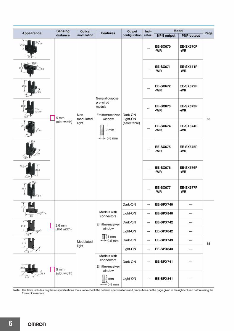
2-2. Adhesive Dispensers
Applicable Models
Modulated Light for Applications Subject to External Light Interference with Attached CableEE-SPX302-W2A
Detection of Valve Operation
Applicable Models
Position Detection on X-Y TablesMechanical problems are prevented by detecting the limits along the X and Y axes.
EE-SPX302-W2A
EE-SPX302-W2A
Motor Adhesive cylinder
Adhesive dispensers apply an adhesive to hold components on a printed wiring board in position before they are soldered.
EE-SX67/47 Series EE-SPX303/403EE-SX77/87 Series EE-SPX302/402-W2AEE-SX91 Series EE-SPX304/404-W2A EE-SPX305/405-W2A
A Sensor detects the number of times the valve is opened so that the amount o adhesive remaining can be determined.
EE-SX67/47 Series EE-SPX302/402-W2AEE-SX91 Series EE-SPX304/404-W2A EE-SPX305/405-W2A
Modulated Light for Applications Subject to External Light Interference with Attached CableEE-SPX302-W2A

18
2-3. Cream Solder Printers
Applicable Models
100-mA Direct Switchingfor Build-in ApplicationEE-SX770
Horizontal and Vertical Positioning ofthe Solder Roller The horizontal and vertical position of the solder roller isdetected so that solder can be coated without waste. Applicable Models
Detection of the Screen Die EndThe position of the die is detected so that thescreen can be accurately positioned onto it.
Solder screen
PWB diePWB
Rail EE-SX970
Solder roller
EE-SX971
Solder screen
These devices print a cream solder onto printer wiring boards before components are mounted.
EE-SX67/47 SeriesEE-SX77/87 SeriesEE-SX91 SeriesEE-SX97 Series
EE-SX67 SeriesEE-SX91 SeriesEE-SX97 Series
Built-in Connector for Downsizing and Easier ConnectionEE-SX971

19
2-4. Lead Component Inserters
Applicable Models
Position Detection on X-Y TablesMechanical problems are prevented by detectingthe limits along the X and Y axes.
Detection of Chip Case Ends
Applicable Models
EE-SPX305-W2A
EE-SPX303N/403N
This device automatically inserts radial or axial lead components onto the printed wiring boards.
EE-SX67/47 SeriesEE-SX91 Series EE-SPX303N/403N EE-SPX302/402-W2A EE-SPX304/404-W2AEE-SPX305/405-W2AEE-SX97 Series
Modulated Light for Applications Subject to External Light Interference with Attached CableEE-SPX302-W2A
Modulated Light for Applications Subject to External Light Interference with 13-mm Slot EE-SPX303N/403N
EE-SX67/47 Series EE-SPX303N/403NEE-SX91 Series EE-SPX302/402-W2AEE-SX97 Series EE-SPX304/404-W2A EE-SPX305/405-W2A
As component cases are fed and the components are mounted, Sensors are waiting to detect when the case has completed processing.
application.fm 19 ページ 2010年8月30日 月曜日 午後12時57分

20
2-5. Sensing an Arm’s Starting Point
EE-SPX303N/403N
Feeder

21
3. Electronic Component Manufacturing Equipment3-1. Assembly Robots
Detection of Motor Rotationand Workpiece Position
Applicable Models
EE-SX970Robots are used to manufacture relays, switches, and other electronic components. The work performed in assembly is based on vertical movement. Completed parts are automatically moved to pallets.
Cams are used to detect motor rotation, while the bottom limit of the workpiece is detected to ensure accurate operation.
EE-SX67/47 SeriesEE-SX77/87 SeriesEE-SX91 SeriesEE-SX97 Series
Built-in Connector for Downsizing and Easier ConnectionEE-SX970

22
3-2. Sequential Presses
Applicable Models
Detection of Motor Rotation for Sequential Parts Feeders
Upper and Lower Limit Detectionfor Press Molds
Applicable Models
EE-SX971
Press mold
EE-SX970
A series of different types of presses are aligned to sequentially produce relays, switches, and other components containing contacts.
The upper and lower limits of press molds must be detected to properly time the movement of reed frames and the press mold.
EE-SX67/47 SeriesEE-SX77/87 SeriesEE-SX91 SeriesEE-SX97 Series
A cam is used with a Sensor to detect motor rotation and thus feed the hoop material at set intervals.
EE-SX67/47 SeriesEE-SX77/87 SeriesEE-SX91 SeriesEE-SX97 Series
Built-in Connector for Downsizing and Easier ConnectionEE-SX971
Built-in Connector for Downsizing and Easier ConnectionEE-SX970

23
3-3. Component Inspectors
Cam Position Detection
Workpiece Position DetectionAfter Inspection
Applicable Models
100-mA Direct Switchingfor Built-in ApplicationEE-SX673
EE-SX971
EE-SX673
Applicable Models
These inspectors check all optical components, such as LEDs and phototransistors, and consist of both a parts feeder and devices that distinguish good components from no-good ones.
After inspection, a Sensor activates a mechanism when necessary to separate out no-good components.
EE-SX67/47 SeriesEE-SX77/87 SeriesEE-SX91 SeriesEE-SX97 Series
Photomicrosensors detect various cams to ensure proper timing of various operations.
EE-SX67/47 SeriesEE-SX77/87 SeriesEE-SX91 SeriesEE-SX97 Series
Built-in Connector for Downsizing and Easier ConnectionEE-SX971

Photomicrosensors
24
Definition of Terms
Term Reference diagram Explanation
Non-modulated light ---Method used to detect light steadily emitted by the emitter element.
Light modulation ---Method used to detect light emitted in pulses by the emitter element.
Sensing distance
Through-beam (with slot)
The slot width, i.e., the distance between the opposing faces of the emitter and receiver.
Through-beam The minimum distance that can be set con-
sidering factors such as the variation be-tween products and fluctuations in temperature.Note: The actual value under standard conditions for
each method is longer than the rated sensing distance.
Retro-reflective
Diffuse-reflective
The minimum distance that can be set for a standard sensing object (white paper) con-sidering factors such as the variation be-tween products and fluctuations in temperature.Note: The actual value under standard conditions for
each method is longer than the rated sensing distance.
Differential distanceThe difference in distance between the op-erating point and releasing point.
Response frequency
The frequency at which an object satisfying specified conditions (size, transparency rate, reflection factor, sensing distance, and power supply voltage) can be repeatedly de-tected.
Response time
The delay from the light input turning ON/OFF until the control output operation or re-lease operation. The following equation generally applies.Operating time (Ton) ≈ Releasing time (Toff)
Ambient illuminationThe level of illumination on the sensing sur-face that enables stable operation of the Sensor.
Sensing distanceSlot width
Emitter Receiver
Sensing distance
Emitter Receiver
Sensing distance
Reflective panelEmitter/receiver
Sensing object
Emitter/receiver
Sensing distance
Through-beam
Reflective
Operates
Releases
Sensing object
Differential distance
Operates
Releases
Operates
Releases
Disk
1 mm1 mm2.1 mm
t = 0.2 mm
Example for Slot-type Photomicrosensor
Operating time
Light input
Control output
t
0
0
Releasing time( ton) ( toff)
t
ReceiverReceiver
Receiver
White paper White paper
White paper

Photomicrosensors
25
Interpreting Engineering Data
Sensing Position Characteristics Repeated Sensing Position Characteristics
Example for the EE-SX770 Example for the EE-SX770
The graph shows the position of the edge of the sensing object where the Sensor will respond.
The graph shows the fluctuation in the position of the edge of the sensing object where the Sensor operates. Use this as a rough guide for the positioning accuracy of the sensing object.
Tr ON
Tr OFF0 1.0 2.0 3.0 4.0 5.0 6.0
Distance d (mm)
d
Tr OFF
Tr 0/V2.16 2.18 2.20 2.22
Distance d (mm)
Vcc = 24 V, No. of repetitions: 20, Ta = 25˚C
d
Δd = ±0.002 mm
Receiver Output Excess Gain vs. Sensing Distance Characteristics
Parallel Movement Characteristics
Example for the EE-SPW311/411 Example for the EE-SPW311/411
• The receiver output excess gain shows values when setting the maximum sensitivity.
• The values above are typical for models with a rated sensing dis-tance of 1 m. It can be seen that the receiver output excess gain is increased by a factor of approximately ten at the rated sensing distance.
• Through-beam Sensor: The graph shows the position of the sensing limit of the receiver when the position of the emitter is constant.
• Retroreflective Sensor: The graph shows the position of the sensing limit of the Reflector when the position of the Sensor is constant.
• Multiple Through-beam Sensors: A range of 1.5 times the amount shown in the graph is required to prevent mutual interfer-ence.
1,000
500300
100
5030
10
53
1
0 0.2 0.4 0.6 0.8 1.0 1.2 1.4 1.6 1.8Distance between sensors (m)
Rec
eive
r ou
tput
exc
ess
gain
(m
ultip
le)
0.2 0.4 0.6 0.8 1 1.2 1.4 1.6 1.8
Distance X
Distance X (m)
Distance Y
140
120
100
80
60
40
20
0
Dis
tanc
e Y
(m
m)

Photomicrosensors
26
Operating Range Characteristics
Example for the EE-SPY301 and EE-SPY401
• The graph shows the point where sensing starts when a standard sensing object is moved perpendicular to the optical axis. The curved line on the right in the graph shows values for when the sensing object is approaches from the right side.
Note: These values are for standard sensing objects. If the sensing object changes, the operating range and sensing distance will also change.
Releases
1211
10
9
8
7
6
5
4
3
2
10−5 −4 −3 −2 −1 0 1 2 3 4 5
Operates
Distance X (mm)
Sensing object: (reflection factor: 90%) White paper (15 × 15 mm2)D
ista
nce
Y (
mm
)
Y
X

Photomicrosensors
27
General Precautions ∗Refer to Precautions section for individual models for specific precautions for each model.
These products cannot be used in safety devices for presses or other safety devices used to protect human life. This product is designed for use in applications for sensing workpieces and workers that will not affect levels of safety.
Be sure to use the product safely according to the following precautions.
● Wiring
Warning
Precautions for Safe Use
Item ExamplesPower SupplyDo not apply any voltage exceed-ing the rated voltage range. Apply-ing any excessive voltage or supplying AC power (100 VAC or higher) to a DC-type sensor may cause the Sensor to explode or burn.
Load Short-circuitDo not short-circuit the load. Doing so may cause the Sensor to explode or burn.
WiringBe sure to wire the Sensor correct-ly and be careful not to connect the polarities incorrectly, otherwise the Sensor may explode or burn.
Connection with No LoadIf connected to the power supply without any load, internal elements may explode or burn. Make sure that a proper load is connected to the Sensor.
AND ConnectionsDo not use AND connections such as in the example shown in the diagram here. Voltage will be applied to the Vcc terminal without the GND terminal of Sensor 2 being securely grounded, and may cause the Sensor to malfunction. Depending on the model used, inrush current to Sensor 2 when Sensor 1 is turned ON may result in malfunction.
· DC 3-wire NPN output sensor
Load
Sensor
Brown
BlueBlack
· DC 3-wire NPN output sensor
Sensor
Brown
BlueBlack
Load
(Load short-circuit)
Load
Sensor
Brown
BlueBlack
· DC 3-wire NPN output sensor (Example) Wrong polarity
· DC 3-wire NPN output sensor (Example) Wrong polarity or wrong wiring
Load
Sensor
Brown
Blue
BlackSensor
LoadBrown
BlackBlue
Sensor
Brown
Blue
Black
· DC 3-wire NPN output sensor12 to 24 VDC
0 V
Sensor
Brown (Vcc)
Blue (GND)
Black (OUT)
Black (OUT)
5 to 24 VDC
0 V
Load
Sensor
Brown (Vcc)
Blue (GND)
Sensor 1 Sensor 2

Photomicrosensors
28
● Installation• The Sensors without light modulation (i.e., EE-SX, EE-SY)
are built into the device being used and are, therefore, not equipped to deal with interference from an external light source. When using a Sensor without light modulation in an area exposed to an incandescent light or other external light interference, install so as to minimize the effects of external light sources.
• Mount the Sensors securely on a flat surface. • Mount the Sensor with two M3 screws, using a spring
washer to ensure the screws will not become loose. Use a tightening force of 6 kgf·cm (0.59 N·m) max.
Note: Be sure to read the precautions for the model being used before tightening the screws.
• Install so that nothing can collide with the sensing section of the Sensor. Damage to the sensing surface will result in inferior performance.
• Before using the Sensor, check to be sure that it has not become loose due to vibration or shock.
● WiringSurge• If there is surge in the power supply, try connecting a
capacitor (with a capacitance of 0.1 to 1 μF) or a Zener diode (ZD in the diagram below, with a rated voltage of 30 to 35 V). Use the Sensor only after confirming that the surge has been removed.
• When driving a small inductive load, such as a relay, wire as shown below. (Be sure to connect a diode to absorb the reverse voltage.)
• Separate the wiring for the Sensor from high-tension lines or power lines. If the wiring is routed in the same conduit or duct as such lines, the Sensor will be damaged or its operation will be affected by inductive interference.
• Make sure that the connectors (either dedicated or commercially available) are securely locked.
Voltage Output • A Sensor with an open-collector output can be connected to
a counter with a voltage input by connecting a resistor between the power source and output. Select a resistor with reference to the following example. The resistance of the resistor is generally 4.7 kΩ and its wattage is 1/2 W for a supply voltage of 24 V and 1/4 W for 12 V.Example:
If resistance R = 4.7 kΩ for the EE-SX670, the input voltage at the high level is as follows:
And the input voltage and load current at the low level are as follows:Input voltage VL ≤ 0.4 V(Residual voltage for 40-mA load current)
Note: Refer to the ratings of the Sensor for the residual voltage of the load current.
Terminals• Make sure that the terminals are not subjected to stress
(external force). Stress will cause damage to the terminals.
Precautions for Correct Use
ZD
ZD: Zener diode
L
OUT
0.1 to 1 μF
OUT
+V
0 V
D
Relay X
Input voltage VH = Z
VCC = 4.7 k
× 24 VR + Z 4.7 k + 4.7 k
= 12 V
Residual voltage IC = VCC
= VCC
= 5.1 mA ≤ 40 mAR R
SW main circuit
Tr
+VccEE-SX670
Counter (Voltage input type)Insert a resistor
Output
0 V 0 V
R
24 V Power supply
Z
Input terminal (CP)
(Input impedance: approx. 4.7 kΩ)
Terminal Terminal
Photomicrosensors
29
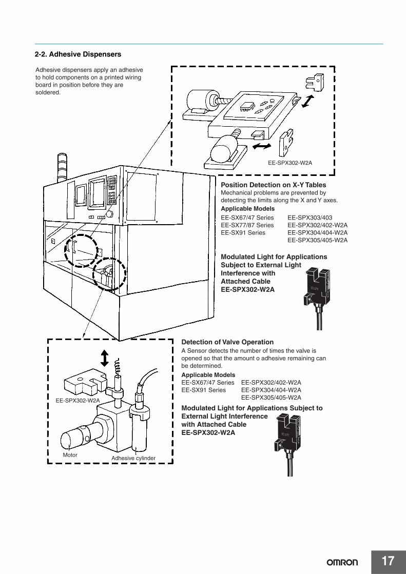
● Design ConsiderationsInfluence of Power Supply and Cable Length (EE-SP Models)When using a Sensor with a model number beginning with EE-SP with light modulation, make sure that the power and cable length are considered in the design. These models are more easily influenced than models with direct light modulation (i.e., Sensors with model numbers beginning with EE-SX or EE-SY).• Sensors with light modulation that are easily affected:
EE-SPX301/401, EE-SPY30@/40@,EE-SPZ301@/401@, EE-SPY31@/41@EE-SPX303/403, EE-SPW311/411,EE-SPX74@/84@, EE-SPX@@@-W
• Sensors with light modulation that are not easily affected:EE-SPX613, EE-SPY801/802∗ All Sensors with model numbers beginning with EE-SX
and EE-SY without light modulation are not easily influenced by power or cable length.
Reasons for Interference from Power and Cable Length on Models with Light Modulation
The emitter LED is lit using pulses for models with light modulation. As a result, the large current required to emit light from the LED will produce pulsation in the current consumption. Photoelectric Sensors have built-in capacitors with sufficient capacity. Therefore, these Sensors are not influenced by pulsating current consumption. Incorporating built-in capacitors with sufficient capacity in compact Photomicrosensors, however, is difficult, thereby resulting in pulsating current consumption. Operation may not be able to keep up with the pulsation in the current consumption depending on the cable length and the type of power supply used, and this may result in unstable operation.
CountermeasuresAdding a CapacitorAttach a capacitor (e.g., film capacitor) of 10 μF min. to the wires as close as possible to the Sensor. (Use a capacitor with a dielectric strength that is at least twice the Sensor's power supply voltage. Do not use tantalum capacitors. Short-circuit malfunctions may result in the capacitor igniting due to the large current flow.)
Cable Length• Design the configuration using a total cable length of 2 m
max. for the Sensor. • To use a cable longer than 2 m, attach a capacitor with a
capacitance of approximately 10 μF to the wires as shown below (the distance between the terminal and the capacitor must be within 2 m). Make sure that the total cable length is no longer than approximately 5 m. To use a cable length longer than 5 m, use a PLC or other means to read the sensor output and then transmit the signals using a PLC with communications functions. Although cables can be extended longer than 5 m, performance will be affected by the noise interference from adjacent cables and other devices and the influence of cable specifications. Voltage drops due to resistance in wiring materials will also influence performance. Therefore, factors, such as the difference in voltage between the end of the cable and the sensor and noise levels, must be given full consideration.
Note: Refer to the precautions for the Sensor being used before extending cables. The length that cables can be extended depends on the Sensor model and cable specifications. EE-SX, EE-SY, and all other Sensors without light modulation are not easily affected by cable length (effective extension from 20 to 50 m is possible).
Emitter (LB)
Main circuit 5 to 24 VDC
10 μF min.
Cur- rent
Vcc
OUT
GND
2 m max.
Capacitance of 10 μF min.
12 to 24 VDC
0 V
Extension cable
OUT

Photomicrosensors
30
Using a Switching Power Supply• Take either of the following countermeasures as required if
connecting a Sensor with optical modulation to a switching power supply.
1. Attach a capacitor of 10 μF min to the wires as close as possible to the Sensor. (Use a capacitor with a dielectric strength that is at least twice the Sensor's power supply voltage. Do not use tantalum capacitors. Short-circuit malfunction may result in the capacitor igniting due to the large current flow.)
2. Connect to the 0-V line of the power source or connect to the power source via a capacitor of approximately 0.47 μF to reduce the impedance of the mounting base to prevent inductive noise from entering the mounting base.
3. Connect the noise filter terminal (neutral terminal to ACG) of the switching power supply to the case (FG) and 0-V terminal of the power supply.
Countermeasures to Handle Inductive Noise
4. Insert a plastic insulator of approximately 10 mm between the Sensor and the mounting base.
Effects of Inductive Noise• When there is inductive noise in the Sensor mounting frame
(metal), the output of the Sensor may be affected. In this case, ensure that there is no electrical potential difference between the Sensor 0-V terminal and the Sensor mounting frame, or put a 0.47-μF capacitor between the 0-V terminal and the frame.
Output Signal Processing• Set a processing speed slower than 100 ms to prevent
noise interference.
Reflective PhotomicrosensorsSensing Distance• The maximum sensing distance of each Reflective
Photomicrosensor model is based on sensing a sheet of white paper with a reflection factor of 90%. The sensing distance varies with the other conditions of the objects being detected.
Typical ExampleEE-SPY30/40 Series
Background Objects• The Reflective Photomicrosensor detects objects by
sensing the difference in the reflection factor between the object and the background, therefore the background objects should not be glossy.
Decrease reflection from the background object, e.g., by providing a sufficient distance to the background or by using a black sponge as the background.
Note: The line connected as mentioned above should be grounded or connected to the mounting base to ensure stable operation.
2 m max.
Capacitance of 10 μF min.
12 to 24 VDC
0 V
Extension cable
OUT
0 V
GC(0.47 μF)
Switching power supply
Mounting base
Sensor +V
Mounting base
To the sensor
SensorTo the power supply
+V
G
0 V
ACG
FG
Grounding
Switching power supply
Input
PowersupplySensor
Mountingframe
0.47 μF
0 V
12 to 24 VDC
Sensing objectWhite paper (reflection factor: 90%)
15
10
5
012 22 32 52 72 102 202 302 502
Sensing area L2 (mm2)
Sen
sing
dis
tanc
e (m
m)
L
L
Sensingobject
Backgroundobject
Photomicrosensors
31
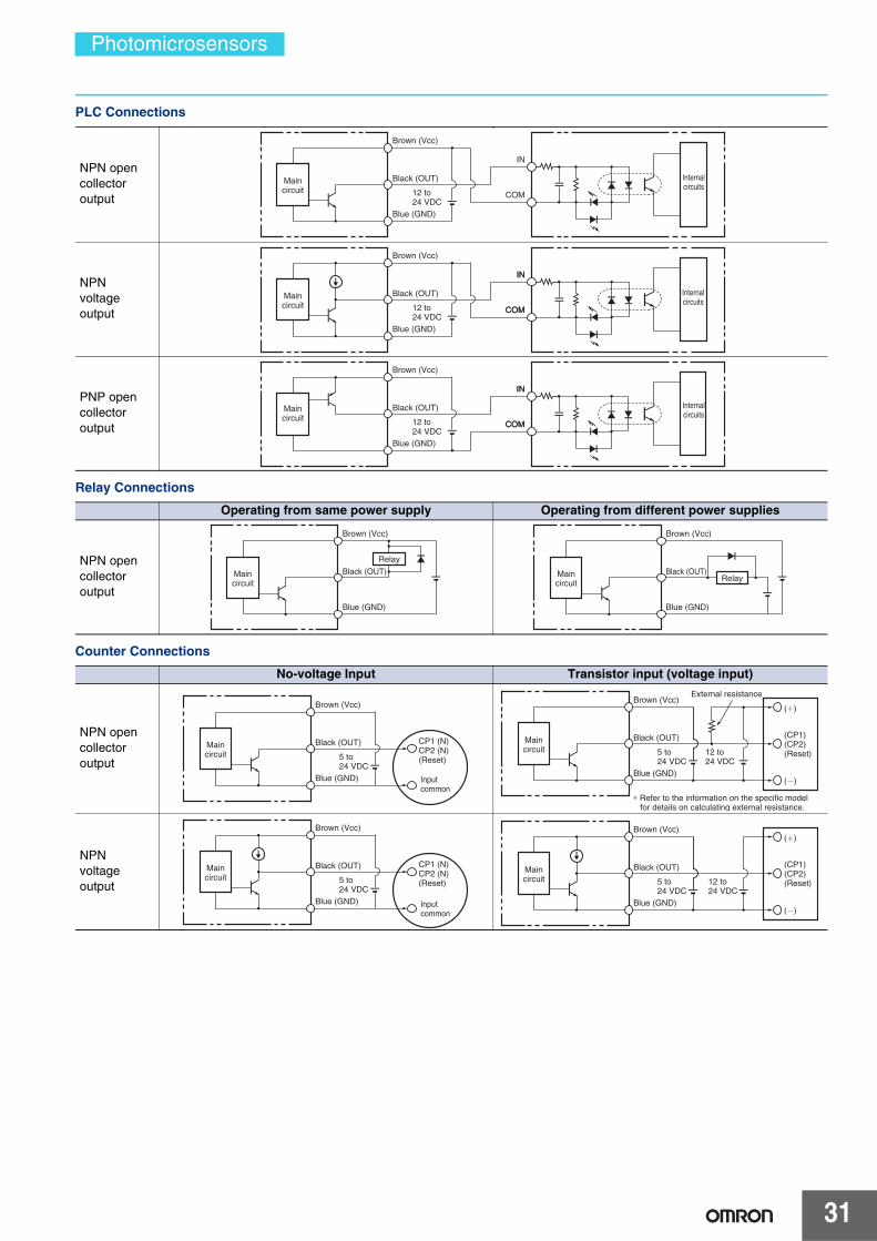
PLC Connections
Relay Connections
Counter Connections
NPN open collector output
a
NPN voltage output
PNP open collector output
Maincircuit
Black (OUT)
12 to 24 VDC
Brown (Vcc)
Blue (GND)
IN
COM
Internalcircuits
Black (OUT)
12 to 24 VDC
Brown (Vcc)
Blue (GND)
IN
COM
IN
COM
Maincircuit
Internalcircuits
Black (OUT)
12 to 24 VDC
Brown (Vcc)
Blue (GND)
IN
COM
IN
COM
Maincircuit
Internalcircuits
Operating from same power supply Operating from different power supplies
NPN open collector output
Maincircuit
Black (OUT)
Brown (Vcc)
Blue (GND)
Relay
Maincircuit
Black (OUT)
Brown (Vcc)
Blue (GND)
Relay
No-voltage Input Transistor input (voltage input)
NPN open collector output
NPN voltage output
Maincircuit
Black (OUT)
5 to 24 VDC
Brown (Vcc)
Blue (GND)
CP1 (N) CP2 (N) (Reset)
Input common
Maincircuit
Black (OUT)
5 to 24 VDC
Brown (Vcc)
Blue (GND)
( )
12 to 24 VDC
( )
(CP1) (CP2) (Reset)
External resistance
∗ Refer to the information on the specific model for details on calculating external resistance.
Maincircuit
Black (OUT)
5 to 24 VDC
Brown (Vcc)
Blue (GND)
CP1 (N) CP2 (N) (Reset)
Inputcommon
Maincircuit
Black (OUT)
5 to 24 VDC
Brown (Vcc)
Blue (GND)
( )
12 to 24 VDC
( )
(CP1) (CP2) (Reset)

Photomicrosensors
32
● Other Precautions• Do not disconnect the Connector from the Sensor when
power is supplied to the Sensor, or Sensor damage could result.
• Avoid installing the Sensor in the following places to prevent malfunction or trouble:
1. Places exposed to dust2. Places exposed to corrosive gases3. Places exposed to water, oil, or chemicals4. Outdoor or places exposed to intensive light, such as direct
sunlight• Be sure to use the Sensor under the rated ambient
temperature.• The Sensor may be dissolved by exposure to organic
solvents, acids, alkali, or aromatic hydrocarbons, causing deterioration in characteristics. Do not expose the Sensor to such chemicals.

33
Slot-type Photomicrosensor
EE-SX97Built-in connector enables downsizing and easier connection. Protective circuit for safe operation. • A built-in connector minimizes the shape and dimensional require-
ments.• Two outputs: light-ON and dark-ON.• Complete lineup including seven different shapes. • Safer operation with built-in power supply reverse polarity protec-
tion.• Output overcurrent protection with a thermal shutdown circuit
(patent pending). *1• The indicator can be seen from many directions to enable installa-
tion in more locations. • Connector with lock that mates with commercially available connec-
tors. *2*1. Output overcurrent protection is provided only on output 2 (OUT2) on NPN models. *2. Recommended connector:
J.S.T. Mfg. Co., Ltd. Contacts: SPHD-001T-P0.5, Housing: PAP-04V-SAsk the manufacturer of the connector for details.
Be sure to read the Safety Precautions on page 37.
Features
Built-in Connector for Downsizing and Easier ConnectionA built-in connector minimizes the shape and dimensional requirements. And wiring costs can be reduced by using commerciallyavailable connectors.
Safer Operation with Built-in Power Supply Reverse Polarity ProtectionThe built-in power supply reverse polarity protection protectsagainst reverse connection of the power supply or outputs forsafer operation at the assembly site.
Built-in Thermal Shutdown CircuitControl output 2 on models with NPN outputs is protectedfrom output overcurrents by a built-in thermal shutdown cir-cuit.
Easy-to-see IndicatorThe indicator can be seen from up to four directions to enableinstallation in more locations.
Two Outputs: Light-ON and Dark-ONAll models provide both a light-ON and dark-ON output so thatthe output can be switched according to the application simplyby changing the wiring.
Previous Model
22.2 22.0
(16.2)(2.2)
EE-SX97 Series
Approx.
40% Smaller
Recommended Connector:J.S.T. Mfg. Co., Ltd. Contacts: SPHD-001T-P0.5, Housing: PAP-04V-S*Ask the manufacturer of the connector for details.
Use Commercial Connectors
The use of a commercially available connector simplifies connections and the positive lock holds the connector in place.
Reverse polarity protection
NPN
GND (0 V)
OUT2
OUT1(Control output)
(Control output)
Vcc
Load 1
5 to 24 VDC
Load 2Main circuit
1
2
3
4
Light indicator (orange)
Display
EE-SX97
34
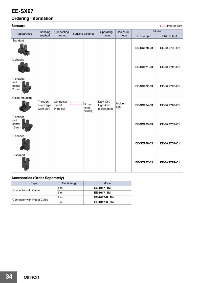
Ordering Information
Sensors
Accessories (Order Separately)
AppearanceSensing method
Connecting method
Sensing distanceOperating
modeIndicator
mode
Model
NPN output PNP output
Through-beam type (with slot)
Connector model (4 poles)
Dark-ON/Light-ON(selectable)
Incident light
EE-SX970-C1 EE-SX970P-C1
EE-SX971-C1 EE-SX971P-C1
EE-SX972-C1 EE-SX972P-C1
EE-SX974-C1 EE-SX974P-C1
EE-SX975-C1 EE-SX975P-C1
EE-SX976-C1 EE-SX976P-C1
EE-SX977-C1 EE-SX977P-C1
Type Cable length Model
Connector with Cable1 m EE-1017 1M
3 m EE-1017 3M
Connector with Robot Cable1 m EE-1017-R 1M
3 m EE-1017-R 3M
Infrared light
Standard
5 mm (slot width)
L-shaped
T-shaped,slot center7 mm
Close-mounting
T-shaped,slot center10 mm
F-shaped
R-shaped

EE-SX97
35
Ratings and Specifications
*1. The differential distance is the value when a sensing object is moved in a lateral direction to the slot.*2. The response frequency was measured by detecting the following rotating disk.
Connector
Type Standard L-shapedT-shaped,slot center
7 mm
Close-mount-ing
T-shaped,slot center
10 mmF-shaped R-shaped
NPN EE-SX970-C1 EE-SX971-C1 EE-SX972-C1 EE-SX974-C1 EE-SX975-C1 EE-SX976-C1 EE-SX977-C1
Item PNP EE-SX970P-C1 EE-SX971P-C1 EE-SX972P-C1 EE-SX974P-C1 EE-SX975P-C1 EE-SX976P-C1 EE-SX977P-C1
Sensing distance 5 mm (slot width)
Sensing object Opaque: 2 × 0.8 mm min.
Differential distance 0.025 mm max. *1
Light source (Peak wave-length)
Infrared LED with a peak wavelength of 940 nm
Indicator Light indicator (orange LED)
Supply voltage 5 to 24 VDC ±10%, ripple (p-p): 10% max.
Current consumption 21 mA max.
Control outputLoad power supply voltage: 5 to 24 VDC, Load current: 50 mA max., Off-state current : 0.5mA max,50 mA load current with a residual voltage of 1.0 V max., 5 mA load current with a residual voltage of 0.4 V max.
Protection circuitPower supply reverse polarity protection; output reverse polarity protection; overcurrent protection (only OUT2 on models with NPN output)
Response frequency 1 kHz min. (3 kHz average) *2
Ambient illumination 1,000 lx max. with fluorescent light on the surface of the receiver
Ambient temperature range
Operating: −25 to 55°C Storage: −30 to 80°C (with no icing or condensation)
Ambient humidity range Operating: 5% to 85% Storage: 5% to 95% (with no icing or condensation)
Vibration resistance (De-struction)
10 to 2,000 Hz 0.75-mm single amplitude (15-min periods, 10 cycles) each in X, Y, and Z directions
Shock resistance (De-struction)
Destruction: 500 m/s2 for 3 times each in X, Y, and Z directions
Degree of protection IEC 60529 IP50
Connecting method Connector
Weight (Packed state) Approx. 3 g
Mate-rial
Case/Cover Polybutylene terephthalate (PBT)
Emitter/receiver Polycarbonate (PC)
Product Connector with Cable Connector with Robot Cable
Model EE-1017 EE-1017-R
Item Appearance
Contact resistance 25 mΩ max. (at 10 mA DC and 20 mV max.)
Insertion strength 20 N max.
Surplus strength 1.5 N min.
Cable length 1 m, 3 m
Ambient temperature range −10 to +60°C
MaterialsHousing Nylon
Contact Phosphor bronze
Disk
1 mm1 mm2.1 mm
t = 0.2 mm

EE-SX97
36
Engineering Data (Typical)
I/O Circuit Diagrams
Sensing Position Characteristics Sensing Position Characteristics Repeated Sensing Position Character-
isticsEE-SX970 EE-SX970 EE-SX970
Output configu-ration
ModelOutput transistor operation status
Timing charts Output circuit
NPN output
EE-SX970-C1EE-SX971-C1EE-SX972-C1EE-SX974-C1EE-SX975-C1EE-SX976-C1EE-SX977-C1
OUT1:Light-ONOUT2:Dark-ON
PNP output
EE-SX970P-C1EE-SX971P-C1EE-SX972P-C1EE-SX974P-C1EE-SX975P-C1EE-SX976P-C1EE-SX977P-C1
Dark-ON
Light-ON0 1 2 3 4 5 6
Distance d (mm)
d
Insert direction
Dark-ON
Light-ON0 1 2 3 4 5 6
Distance d (mm)
d
Insert direction
Dark-ON
Light-ON3.50 3.52 3.54 3.56
Distance d (mm)Vcc = 24 V, No. of repetitions: 20, Ta = 25°CDifferential distance = 0.025 mm max.
d
d = ±0.002
Insert direction
Note: Data is provided for dark conditions. Light in-terference and the translucence of the sensingobject can affect operation.
ON
OFF
Operates
Releases
ON
OFF
Operates
Releases
ON
OFF
Light incident
Light interrupted
Load 1(relay)
Output 1transistor
Light indicator (orange)
Output 2transistor
Load 2(relay)
1
2
3
4
1
2
3
4
GND (0 V)
OUT2
OUT1(Control output)
(Control output)
Vcc
Load 1
5 to 24 VDC
Load 2
Main circuit
Light indicator (orange)
Connector pin arrangement
1
2
3
4
1
2
3
4GND (0 V)
OUT2
OUT1
(Control output)
(Control output)
Vcc
Load 1
5 to 24 VDC
Load 2
Main circuit
Light indicator (orange)
Connector pin arrangement

EE-SX97
37
Safety Precautions
Refer to Warranty and Limitations of Liability.
This product is not designed or rated for ensur-ing safety of persons either directly or indirectly.Do not use it for such purposes.
● Operating EnvironmentThese Photomicrosensors have an IP50 (conforms to IEC)enclosure and do not have a water-proof or dust-proof struc-ture. Therefore, do not use them in applications in which thesensor will be subjected to splashes from water, oil, or anyother liquid. Liquid entering the Sensor may result in malfunc-tion.
Make sure that this product is used within the rated ambientenvironment conditions.
● Installation• Mount the Sensor with two M3 screws, using plain washers
and spring washers to ensure the screws will not becomeloose. Use a tightening force of 0.54 N·m max.
● WiringUnused Output LinesBe sure to isolate output lines that are not going to be used.
Wiring methodConnection is made using a connector. Do not solder to thepins (leads). The pins (leads) are soldered to the internalboard of the Sensor. Therefore, direct soldering of the pins(leads) may result in an internal disconnection causing mal-function.
● Others• The power cable connected to the Sensor must not be more
than 10 m in length.• Only output 2 (OUT2) on NPN models is provided with over-
current protection. If an overcurrent occurs, heat generated by the output tran-sistor will activate the thermal shutdown circuit and OUT2will turn OFF. Check the wiring and load current and cyclethe power supply. If there is no overcurrent, normal opera-tion will be resumed. (The thermal shutdown circuit will beactivated again if there is an overcurrent.) This function does not provide protection against load shortcircuits. If the electric power of the output transistor increas-es due to a load short-circuit or near load short-circuit, theSensor may be damaged.
• An output pulse may occur when the power supply is turnedON depending on the power supply and other conditions.The operation of the Sensor will be stable 100 ms after turn-ing ON the power supply.
WARNING
Precautions for Safe Use
Precautions for Correct Use

EE-SX97
38
Dimensions
Sensors
(Unit: mm)Tolerance class IT16 applies to dimensions in this datasheet unless otherwise specified.
2026
Optical axis
Slit
Indicator windowIndicator window
7
22
10.8
7.4
9
3.2
2.23.9
513.4
0.86.8
2
2
1 2
20
3.2
Four, R1.6
2.6
13.8 Two, M3
3.73.7
2.1
43
20±0.1
EE-SX970-C1EE-SX970P-C1
Terminal Arrangement
A + Vcc
B 1 OUTPUT1
C 2 OUTPUT2
D − GND (0 V)
Mounting screw holes
20
20
14.7
73.2
2.23.9
12.8
13.4
15.5
9
7.2
5
3.2
Four, R1.6
2.6
9
1 2 43
Two, M3
20±0.1
26.2
2
3.72.1
0.86.8
210.8
3.7
Optical axis
Slit
Indicator window
EE-SX971-C1EE-SX971P-C1
Terminal Arrangement
A + Vcc
B 1 OUTPUT1
C 2 OUTPUT2
D − GND (0 V)
Mounting screw holes
26
37
13.7
13.42.6
2213
6.80.8
4.11.6
6.2
20
Four, R1.6
2
10.89
5
3.7
12.6
1 2 43
Two, M3
20±0.1
2
Optical axis
Slit
Indicator windowIndicator window
EE-SX972-C1EE-SX972P-C1
Terminal Arrangement
A + Vcc
B 1 OUTPUT1
C 2 OUTPUT2
D − GND (0 V)
Mounting screw holes

EE-SX97
39
21.7
7
7
12.8
13.40.8
2
2.5
6.8
15.5
9
2.6
2
5
3.5
Two, 3.5 dia.
1 2 43
Two, M3
7±0.1
Optical axis
Slit
Indicator window
EE-SX974-C1EE-SX974P-C1
Terminal Arrangement
A + Vcc
B 1 OUTPUT1
C 2 OUTPUT2
D − GND (0 V)
Mounting screw holes
1 2 43
26
4
10
22
9
2.6
3.710.8
13
16.7
13.45
20
6.80.8
24.1
2.5
6
Four, R1.6
2
Two, M3
20±0.1
Optical axis
Slit
Indicator windowIndicator window
EE-SX975-C1EE-SX975P-C1
Terminal Arrangement
A + Vcc
B 1 OUTPUT1
C 2 OUTPUT2
D − GND (0 V)
Mounting screw holes
22
6.73.7
13.27
Two, R1.62.6 dia.
2.4 dia.
2.1
9
2.6
2.5
3
13.45
3.710.8
2
6.80.8
2
1 2 43
M3
7±0.1
16.3±0.1
Optical axis
Slit
Indicator window
Indicator window
EE-SX976-C1EE-SX976P-C1
Terminal Arrangement
A + Vcc
B 1 OUTPUT1
C 2 OUTPUT2
D − GND (0 V)
Mounting screw holes

EE-SX97
40
Accessories (Order Separately)Connector
6.7 3.7
13.27
Two, R1.6
2.122
9
2.6
6.8
2
0.8
3
13.42.55
3.710.8
16.3
2
1 2 43
2.6 dia.
2.4 dia.
M3
7±0.1
16.3±0.1
Optical axis
Slit
Indicator window
Indicator window
EE-SX977-C1EE-SX977P-C1
Terminal Arrangement
A + Vcc
B 1 OUTPUT1
C 2 OUTPUT2
D − GND (0 V)
Mounting screw holes
1234
Connector with Cable: EE-1017Vinyl insulated round cord: 4 dia., 4 cores,(Cross section area of conductor: 0.2 mm2/ insulator: 1.1 mm dia.)
Connector with Robot Cable: EE-1017-RRobot instrumentation cord: 4 dia., 4 cores,(Cross section area of conductor: 0.2 mm2/ insulator: 1.1 mm dia.)
210
5.8 8 20±5 1,000+50
0 25±5 15±5(8)
Connector with CableEE-1017Connector with Robot CableEE-1017-R
Terminal Arrangement
A + Brown
B 1 Black
C 2 White
D − Blue

41
Compact Pre-wired Photomicrosensor with Built-in Amplifier (Non-modulated)
EE-SX91Meeting Customer Needs with Compact Sensors that Mount with M3 Screws• Both light-ON and dark-ON outputs provided.
• A compact size and choice of five models for a wide range of applications.
• Compact NPN and PNP output models.
• Mount using M3 or M2 screws.
• Indicator is visible in many directions for installationin any location.
• Maximum load current of 100 mA.
• Flexible robot cables are standard on all models.
Be sure to read Safety Precautions on page 46.
Features
A Compact Size and Choice of Five Models for a Wide Range of ApplicationsSelect any of five models to minimize the space required.
Compact NPN and PNP Output ModelsBoth NPN and PNP output models are available for use according to system requirements.
Maximum Load Current of 100 mAOutput control of up to 100 mA is supported for either NPN or PNP outputs.
Flexible Robot Cables: Standard on All ModelsRobot Cables are effective for moving parts, and are provided as standard equipment with all models.
Both Light-ON and Dark-ON OutputsBoth light-ON and dark-ON outputs are provided on all models, allowing outputs to be switched by simply changing the wiring according to the application.
Indicator Visible from Many Directions for Installation in Any LocationThe light indicator can be checked from up to four directions.
Mount Using M3 or M2 ScrewsThe EE-SX91 can be mounted using M3 or M2 screws, so it can easily replace an existing compact sensor mounted with M2 screws.

EE-SX91
42
Ordering Information
List of ModelsModels with Robot Cables
* Prewired models with a 3-m cable are also available. When ordering, specify the cable length by adding “3M” for the end of the model number (e.g., EE-SX910-R 3M).
Appearance Sensing method
Sensing distance
Output configuration
Indicator mode
Connecting method
(Cable length)
Model
NPN output PNP output
Standard
Through-beam type(with slot)
Light-ONDark-ON
(2 outputs)
Lit when light is incident
Pre-wired models (1 m)
EE-SX910-R 1M * EE-SX910P-R 1M *
L-shaped
EE-SX911-R 1M * EE-SX911P-R 1M *
F-shaped
EE-SX912-R 1M * EE-SX912P-R 1M *
R-shaped
EE-SX913-R 1M * EE-SX913P-R 1M *
U-shaped
EE-SX914-R 1M * EE-SX914P-R 1M *
Infrared light
5 mm (slot width)

EE-SX91
43
Ratings and Specifications
* The response frequency was measured by detecting the following rotating disk. The response times for light incidence and light interruption are shown in the timing chart.
Item
Type Standard L-shaped F-shaped R-shaped U-shaped
NPN models Pre-wired models EE-SX910-R EE-SX911-R EE-SX912-R EE-SX913-R EE-SX914-R
PNP models Pre-wired models EE-SX910P-R EE-SX911P-R EE-SX912P-R EE-SX913P-R EE-SX914P-R
Sensing distance 5 mm (slot width)
Sensing object Opaque: 1.2 × 0.8 mm min.
Differential distance 0.025 mm max.
Light source GaAs infrared LED with a peak wavelength of 940 nm
Indicator Light indicator (red LED)
Supply voltage 5 to 24 VDC ±10%, ripple (p-p): 10% max.
Current consumption 15 mA max.
Control output
Load power supply voltage: 5 to 24 VDCLoad current: 100 mA max.OFF current: 0.5 mA max.100 mA load current with a residual voltage of 1.0 V max.5 mA load current with a residual voltage of 0.4 V max.
Protection circuits Power supply reverse polarity protection; output reverse polarity protection
Response frequency 3 kHz min. (8 kHz average) Light incident: 15 μs average; light interrupted: 40 μs average*
Ambient illumination 1,000 lx max. with fluorescent light on the surface of the receiver
Ambient temperature range Operating: −25 to 55°CStorage: −30 to 80°C (with no icing or condensation)
Ambient humidity range Operating: 5% to 85% Storage: 5% to 95% (with no icing or condensation)
Vibration resistance (Destruction) 10 to 2,000 Hz0.75-mm single amplitude for 2.5 h (15-min periods, 10 cycles) each in X, Y, and Z directions
Shock resistance (Destruction) 500 m/s2 for 3 times each in X, Y, and Z directions
Degree of protection IEC60529 IP50
Connecting method Pre-wired Models (standard cable length: 1 m)
Weight(packed state)
Pre-wired Models Approx. 17 g
Models with Con-nectors Approx. 7 g
Mate-rials
Case/cover Polybutylene phthalate (PBT)
Emitter/receiver Polycarbonate (PC)
1 mm2 mm
2 mm
t=0.2 mm40 μs avg.15 μs avg.
Disk
ONOFF
ONOFF
OUT1 outputtransistor
OUT2 outputtransistor
Light incidentLight interrupted

EE-SX91
44
Engineering Data (Typical)
Sensing Position CharacteristicsEE-SX910 EE-SX910 EE-SX911
Repeated Sensing Position CharacteristicsEE-SX910
0 1 2 3 4 5 6
Dark-ON
Light-ON
Distance d (mm)
Insertion direction
d
0 1 2 3 4 5 6
d
Dark-ON
Light-ON
Insertion direction
Distance d (mm)
0 1 2 3 4 5 6
Dark-ON
Light-ON
Insertion direction
Distance d (mm)
d
3.14 3.16 3.18 3.2
d
Dark-ON
Light-ON
Vcc = 24 V, No. of repetitions: 20, Ta = 25°C (Differential distance = 0.025 mm max.)
Distance d (mm)
d=±0.002
Note: The data applies to dark status. Operation may be affected by external light interference or light coming through the sensing object.

EE-SX91
45
I/O Circuit Diagrams
Output type Model Output transistor
operation status Timing charts Output circuit
NPN output
EE-SX910-REE-SX911-REE-SX912-REE-SX913-REE-SX914-R
OUT1: Light-ONOUT2: Dark-ON
PNP output
EE-SX910P-REE-SX911P-REE-SX912P-REE-SX913P-REE-SX914P-R
Light incidentLight interrupted
(Blue)
OUT2(White)
OUT1(Black)
Load 1
Load 2Maincircuit
1
4
2
3
Lightindicator
Brown
5 to 24 VDC
ON
OFF
Light indicator (red)
ON
OFFOutput 1 transistor
Operates
Releases
Load 1
(e.g., relay) (Brown)
Load 2
Load 1
1
4
2
3
Maincircuit
Lightindicator
5 to 24 VDC
(Blue)
OUT2(White)
OUT1(Black)
ON
OFF
Output 2 transistor
Load 2 Operates
Releases(e.g., relay)

EE-SX91
46
Safety Precautions
Refer to Warranty and Limitations of Liability.
This product is not designed or rated for ensuring safety of persons either directly or indirectly. Do not use it for such purposes.
• Power Supply VoltageDo not exceed the voltage range indicated in the specifications. Applying a voltage exceeding the specifications or using an AC power supply may result in rupture or burning.
• Faulty WiringDo not reverse the power supply polarity. Doing so may result in rupture or burning.
• Do not short-circuit the load. (Do not connect to the power supply.)Doing so may result in rupture or burning.
• Dispose of this product as industrial waste.
● Installation• It is assumed that EE-SX91 Sensors will be built into a device.
These Sensors use non-modulated light and are not equipped to deal with interference from an external light source. When they are used in locations subject to external light interference, such as near a window or under an incandescent light, install them to minimize the effects of external light interference.
• Mount the Sensors securely on a flat surface.• Use M3 or M2.0 screws to secure the Photomicrosensor. (The
stronger M3 screws are recommended. In addition, use flat washers and spring washers to prevent the screws from loosening.) Refer to the following table for the correct tightening torque.
• If the Sensor is to be used on a moving part, secure the cable connection point so that it is not directly subjected to stress.
● WiringUnused Output LinesBe sure to isolate output lines that are not going to be used.
Connecting to Devices with Voltage Input SpecificationsA Sensor with an open-collector output can be connected to a counter with a voltage input by connecting a resistor between the power source and output. Select a resistor with reference to the following example. The resistance of the resistor is generally 4.7 kΩ and its wattage is 1/2 W for a supply voltage of 24 V and 1/4 W for 12 V.
Example: EE-SX91 SeriesLoad Resistance of 4.7 kΩ Connected in a Counter
Counter Specifications
The high and low levels are found using the following formulas. The input device specifications must satisfy both formulas.
High level:
Low level:
Input voltage VL ≤ 1.0 V (Residual voltage for 100-mA load current)
Note: Refer to the ratings of the Sensor for the residual voltage of the load current.
WARNING
Precautions for Safe Use
Sensor
Brown
Blue
LoadLoadBlack
White
Sensor
Brown
Blue
Black
White
−
+
LoadLoad
+
Sensor
Brown
Blue
+
−
Black
White
Load
d short-circuit)(LoaLoad
ck
(
Precautions for Correct Use
Screw diameter Tightening torqueM2.0 0.15 N·m max.M3 0.54 N·m max.
Input impedance 5.6 KΩ
Voltage judged as high level (input ON) 4.5 to 30 VDC
Voltage judged as low level (input OFF) 0 to 2 VDC
SW main circuit
Tr
+VccEE-SX91 series Counter (Voltage input type)
Insert a resistor
Output
0 V 0 V
R
24 V Power supply
Z
Input terminal (CP)
(Input impedance: approx. 5.6 kΩ)
Input voltage VH = R+Z
ZVcc =
4.7 k+5.6 k5.6 k × 24 V = 13 V
Load current Ic =R
Vcc= = 5.1 mA ≤ 100 mA
R24 V

EE-SX91
47
● Other Precautions• Do not disconnect the Connector from the Sensor when power is
supplied to the Sensor, or Sensor damage could result.• Do not install the Sensor in the following places to prevent
malfunction or trouble:1. Places exposed to dust or oil mist2. Places exposed to corrosive gas3. Places directly or indirectly exposed to water, oil, or chemicals4. Outdoor or places exposed to intensive light, such as direct
sunlight• Be sure to use the Sensor under the rated ambient temperature.• The Sensor may be dissolved by exposure to organic solvents,
acids, alkali, or aromatic hydrocarbons, aliphatic chloride hydrocarbons causing deterioration in characteristics. Do not expose the Sensor to such chemicals.
• Make sure the total length of the power cable connected to the product is less than 10 m.
EE-SX91
48
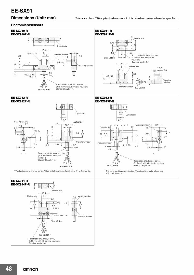
Dimensions (Unit: mm) Tolerance class IT16 applies to dimensions in this datasheet unless otherwise specified.
Photomicrosensors
6
24 Optical axis
Optical axis
Sensing window
3
EE-SX910-R
1.2 0.85.8
Indicator window53.7
13.4
8.32.7
5
4.6 dia.
(2)
2.318.7
Two, 3.2 dia.
6.512 8
Robot cable of 2.8 dia., 4 cores, (0.15 mm2 with 0.8-mm dia. insulator); Standard length: 1 m
EE-SX910-REE-SX910P-R
Optical axis
Optical axis
Indicator window
Sensing window
(2)
10
6.9
3.7
2
3
5
0.8
1.75
1.6 3.2
8
6 12
6
1.2
13.4
412
6.5
EE-SX911-R
(Four, R1.6)Robot cable of 2.8 dia., 4 cores,(0.15 mm2 with 0.8-mm dia.insulator);Standard length: 1 m
EE-SX911-REE-SX911P-R
Sensing window
Optical axis
Optical axis
Indicator window
EE-SX912-R
1.95 1.6
3.2 2 dia.
4.6 dia.3.7
11.7
6.2
12 8
513.43
5
(2)
4
1.5
6.7
1.2
2.3
0.8 8.36.5(R1.6)
6
Robot cable of 2.8 dia., 4 cores,(0.15 mm2 with 0.8-mm dia.insulator);Standard length: 1 m
*
* The lug is used to prevent turning. When installing, make a fixed hole of 2.1 to 2.3 mm dia.
EE-SX912-REE-SX912P-R
*Indicator window
Optical axis
Optical axis
Sensing window
5
13.4
3.7
2 dia.2.34.6 dia.
8 12
1.5(2)
6.74
6
11.7
3
5
6.2
3.2
1.6 1.95
1.2
0.8
EE-SX913-R
(R1.6)8.3 6.5
Robot cable of 2.8 dia., 4 cores,(0.15 mm2 with 0.8-mm dia.insulator);Standard length: 1 m
* The lug is used to prevent turning. When installing, make a fixed hole of 2.1 to 2.3 mm dia.
EE-SX913-REE-SX913P-R
Two, 3.2 dia.
Indicator windowIndicator window
Sensing window
Optical axis
Optical axis
16
6.5
11.5
13.45
3.7
(2) 1.2
0.8
63
8.3 8.3
8
EE-SX914-R
Robot cable of 2.8 dia., 4 cores,(0.15 mm2 with 0.8-mm dia. insulator);Standard length: 1 m
EE-SX914-REE-SX914P-R

49
Photomicrosensor with Slim Cable (Non-modulated)
EE-SX77/87Slim, Compact Photomicrosensor that is still easy to use.• Compact, thin profile enables dense mounting.
• Indicator is visible from both sides.
• Wide operating voltage range: 5 to 24 VDC
Be sure to read Safety Precautions on page 52.
Ordering Information
Pre-wired Models
* Models with NPN outputs are available with pre-wired e-CON connectors. Specify an NPN output by adding "-ECON" and the cable length (0.3 m or 2 m) to the end of the model number. (Example: EE-SX770-ECON 0.3M)
Appearance Sensing method
Cable length Sensing distance Output
configuration Indicator modeModel
NPN output* PNP output
Standard
Through-beamtype
(with slot)2 m
Dark-ONIncident light EE-SX770 2M EE-SX770P 2M
No incident light EE-SX770A 2M EE-SX770R 2M
Light-ONIncident light EE-SX870 2M EE-SX870P 2M
No incident light EE-SX870A 2M EE-SX870R 2M
L-shapedDark-ON
Incident light EE-SX771 2M EE-SX771P 2M
No incident light EE-SX771A 2M EE-SX771R 2M
Light-ONIncident light EE-SX871 2M EE-SX871P 2M
No incident light EE-SX871A 2M EE-SX871R 2M
T-shapedDark-ON
Incident light EE-SX772 2M EE-SX772P 2M
No incident light EE-SX772A 2M EE-SX772R 2M
Light-ONIncident light EE-SX872 2M EE-SX872P 2M
No incident light EE-SX872A 2M EE-SX872R 2M
Infrared light
5 mm(slot width)
EE-SX77/87
50
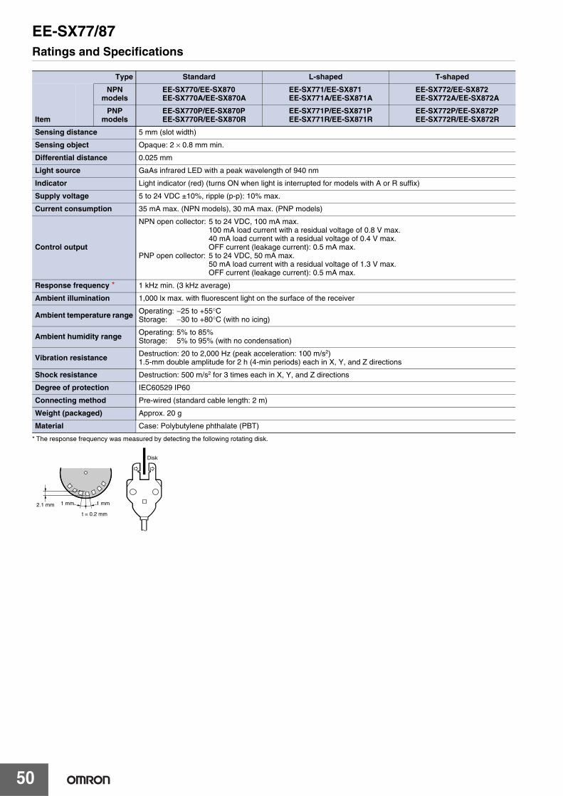
Ratings and Specifications
* The response frequency was measured by detecting the following rotating disk.
Type Standard L-shaped T-shaped
Item
NPNmodels
EE-SX770/EE-SX870EE-SX770A/EE-SX870A
EE-SX771/EE-SX871EE-SX771A/EE-SX871A
EE-SX772/EE-SX872EE-SX772A/EE-SX872A
PNPmodels
EE-SX770P/EE-SX870PEE-SX770R/EE-SX870R
EE-SX771P/EE-SX871PEE-SX771R/EE-SX871R
EE-SX772P/EE-SX872PEE-SX772R/EE-SX872R
Sensing distance 5 mm (slot width)
Sensing object Opaque: 2 × 0.8 mm min.
Differential distance 0.025 mm
Light source GaAs infrared LED with a peak wavelength of 940 nm
Indicator Light indicator (red) (turns ON when light is interrupted for models with A or R suffix)
Supply voltage 5 to 24 VDC ±10%, ripple (p-p): 10% max.
Current consumption 35 mA max. (NPN models), 30 mA max. (PNP models)
Control output
NPN open collector: 5 to 24 VDC, 100 mA max.100 mA load current with a residual voltage of 0.8 V max.40 mA load current with a residual voltage of 0.4 V max.OFF current (leakage current): 0.5 mA max.
PNP open collector: 5 to 24 VDC, 50 mA max.50 mA load current with a residual voltage of 1.3 V max.OFF current (leakage current): 0.5 mA max.
Response frequency * 1 kHz min. (3 kHz average)
Ambient illumination 1,000 lx max. with fluorescent light on the surface of the receiver
Ambient temperature range Operating: −25 to +55°CStorage: −30 to +80°C (with no icing)
Ambient humidity range Operating: 5% to 85%Storage: 5% to 95% (with no condensation)
Vibration resistance Destruction: 20 to 2,000 Hz (peak acceleration: 100 m/s2)1.5-mm double amplitude for 2 h (4-min periods) each in X, Y, and Z directions
Shock resistance Destruction: 500 m/s2 for 3 times each in X, Y, and Z directions
Degree of protection IEC60529 IP60
Connecting method Pre-wired (standard cable length: 2 m)
Weight (packaged) Approx. 20 g
Material Case: Polybutylene phthalate (PBT)
Disk
1 mm1 mm2.1 mm
t = 0.2 mm

EE-SX77/87
51
Engineering Data (Typical)
I/O Circuit Diagrams
NPN Output
Sensing Position Characteristics Sensing Position Characteristics Repeated Sensing Position Characteristics
EE-SX770
Model Output configuration Timing charts Output circuit
EE-SX770EE-SX771EE-SX772
Dark-ON
EE-SX870EE-SX871EE-SX872
Light-ON
EE-SX770AEE-SX771AEE-SX772A
Dark-ON
EE-SX870AEE-SX871AEE-SX872A
Light-ON
Tr ON
Tr OFF0 1.0 2.0 3.0 4.0 5.0 6.0
Distance d (mm)
d
Tr ON
Tr OFF0 1.0 2.0 3.0 4.0 5.0 6.0
Distance d (mm)
d
Tr OFF
Tr 0/V2.16 2.18 2.20 2.22
Distance d (mm)
d
d = ±0.002 mm
Vcc = 24 V No. of repetitions: 20, Ta = 25°CNote: The data applies to dark status. Operation
may be affected by external light interference or light coming through the sensing object.
Incident
Interrupted
ON
OFF
ON
OFF
Operates
Releases
Light indicator (red)
Output transistor
Load (e.g., relay)
Light indicator (red)
Load
Main circuit
Blue (GND)
Brown (Vcc)
Black (OUT)(control output)100 mA max.
5 to 24 VDC4
3
1
Light indicator (red)
Output transistor
Incident
Interrupted
ON
OFF
ON
OFF
Operates
Releases
Load (e.g., relay)
Output transistor
Load (e.g., relay)
Incident
Interrupted
ON
OFF
ON
OFF
Operates
Releases
Light indicator (red)
Light indicator (red)
Load
Main circuit
Blue (GND)
Brown (Vcc)
Black (OUT)(control output)100 mA max.
5 to 24 VDC4
3
1
Light indicator (red)
Output transistor
Load (e.g., relay)
Incident
Interrupted
ON
OFF
ON
OFF
Operates
Releases

EE-SX77/87
52
PNP Output
Applicable Connectors
Safety Precautions
Refer to Warranty and Limitations of Liability.
This product is not designed or rated for ensuring safety of persons either directly or indirectly.Do not use it for such purposes.
Make sure that this product is used within the rated ambient environment conditions.
Model Output configuration Timing chart Output circuit
EE-SX770PEE-SX771PEE-SX772P
Dark-ON
EE-SX870PEE-SX871PEE-SX872P
Light-ON
EE-SX770REE-SX771REE-SX772R
Dark-ON
EE-SX870REE-SX871REE-SX872R
Light-ON
Light indicator (red)
Output transistor
Load (e.g., relay)
Incident
Interrupted
ON
OFF
ON
OFF
Operates
Releases
Light indicator (red)
Load
Main circuit
Blue (GND)
Brown (Vcc)
Black (OUT) 5 to 24 VDC4
3
1
Light indicator (red)
Output transistor
Load (e.g., relay)
Incident
Interrupted
ON
OFF
ON
OFF
Operates
Releases
Light indicator (red)
Output transistor
Load (e.g., relay)
Incident
Interrupted
ON
OFF
ON
OFF
Operates
Releases
Light indicator (red)
Load
Main circuit
Blue (GND)
Brown (Vcc)
Black (OUT) 5 to 24 VDC4
3
1
Light indicator (red)
Output transistor
Load (e.g., relay)
Incident
Interrupted
ON
OFF
ON
OFF
Operates
Releases
1
2
34
Note: Pin 2 is not used.
Shield color Pin No. Use
Brown (1) Power supply (+V)
White (2) ---
Blue (3) Power supply (0 V)
Black (4) Output
E39-ECON@M E39-ECONW@M
12
34
15.8
Vinyl-insulated round cable of 4 dia., 4 cores, (0.2 mm2 with 1.1-mm dia. insulator)
12
34
43
12
Vinyl-insulated round cable of 4 dia., 4 cores, (0.2 mm2 with 1.1-mm dia. insulator)
Note: The @ symbol is used to indicate the cable length. The cable length is 2 m or 5 m.
Note: The @ symbol is used to indicate the cable length. The cable length is 0.5 to 2 m in increments of 0.1 m.
Pre-wired e-CON Connector Pin Arrangement
Note: Pin 2 is not used.
WARNING Precautions for Correct Use

EE-SX77/87
53
(Unit: mm)
Dimensions Tolerance class IT16 applies to dimensions in this datasheet unless otherwise specified.
Vinyl-insulated round cable of 2.4 dia., 3 cores, (0.08 mm2 with 0.7-mm dia. insulator); Standard length: 2 m
18
5
2.9
9
22.1
5 dia.
6.2
40.3
0.7
0.312
Optical axis
Optical axis
Two 6 dia.
Indicator window
2,000+50 0
0.45
Two, 3.2 dia. holes
1
StandardEE-SX770/770PEE-SX870/870PEE-SX770A/770REE-SX870A/870R
Indicator window
Optical axis
Six, R3
Four, R1.6
18
12
27.8
21
5 dia.
4
4
4.6
13
4.3
2,000+50 0
Vinyl-insulated round cable of 2.4 dia., 3 cores, (0.08 mm2 with 0.7-mm dia. insulator); Standard length: 2 m
0.7
10.45
Optical axis
125
2.9
9 0.3
0.3
4
L-shapedEE-SX771/771PEE-SX871/871PEE-SX771A/771REE-SX871A/871R
Indicator window
Vinyl-insulated round cable of 2.4 dia., 3 cores,(0.08 mm2 with 0.7-mm dia. insulator); Standard length: 2 m
Opticalaxis
Optical axis
Two, R3
Four,R1.6
12 12
5
2.9
12.3
9
22.1
5 dia.
12.33.3
4 19.1
4.3
2,000+50 0
0.7
0.45
1
T-shapedEE-SX772/772PEE-SX872/872PEE-SX772A/772REE-SX872A/872R

MEMO
54

55
Slot-type Photomicrosensor (Non-modulated) *1
EE-SX47/67Global Standard Slot-type photomicrosensors with 50- to 100-mA direct switching capacity.• Series includes models that enable switching between
dark-ON and light-ON operation.• Response frequency as high as 1 kHz.• Easy operation monitoring with bright light indicator.• Wide operating voltage range: 5 to 24 VDC• Models in which the light indicator turns ON for dark-ON
operation are also available.• A wide range of variations in eight different shapes.• Flexible robot cable is provided as a standard feature. *2
*1. Pre-wired Models are available only in the EE-SX67 Series.*2. Only for Pre-wired Models.
Be sure to read Safety Precautions on page 59.
Ordering Information
Connector
*3. Dark-ON when the L terminal of the connector is opened, and light-ON when the L terminal and positive (+) terminal are connected. Do not connect the L terminal to 0 V when using dark-ON operation. When using light-ON, it is useful to select the connector EE-1001-1. The L terminal and positive (+) terminal of this connector are connected in advance.
Appearance Sensingmethod
Connect-ing method Sensing distance Output
configuration Indicator modeModel
NPN output PNP output
Through-beam type
(with slot)
Connector (4 poles)
Dark-ON/Light-ON(selectable) *3
Incident light EE-SX670 EE-SX670P
No incident light EE-SX670A EE-SX670R
Light-ON Incident light EE-SX470 EE-SX470P
Dark-ON/Light-ON(selectable) *3
Incident light EE-SX671 EE-SX671P
No incident light EE-SX671A EE-SX671R
Light-ON Incident light EE-SX471 EE-SX471P
Dark-ON/Light-ON(selectable) *3
Incident light EE-SX672 EE-SX672P
No incident light EE-SX672A EE-SX672R
Light-ON Incident light EE-SX472 EE-SX472P
Dark-ON/Light-ON(selectable) *3
Incident light EE-SX673 EE-SX673P
No incident light EE-SX673A EE-SX673R
Light-ON Incident light EE-SX473 EE-SX473P
Dark-ON/Light-ON(selectable) *3
Incident light EE-SX674 EE-SX674P
No incident light EE-SX674A EE-SX674R
Light-ON Incident light EE-SX474 EE-SX474P
Dark-ON/Light-ON(selectable) *3 Incident light EE-SX675 EE-SX675P
Dark-ON/Light-ON(selectable) *3 Incident light EE-SX676 EE-SX676P
Dark-ON/Light-ON(selectable) *3 Incident light EE-SX677 EE-SX677P
Infrared light
Standard
5 mm(slot width)
L-shaped
T-shaped,slot center7 mm
Close-mounting
Close-mounting
T-shaped,slot center10 mm
F-shaped
R-shaped

EE-SX47/67
56
Pre-wired Models
* Dark-ON operation can be used when the L terminal is left unconnected or Light-ON operation can be used when the L terminal and positive (+) terminal are connected to each other. Do not connect the L terminal to 0 V when using dark-ON operation.
Accessories (Order Separately) Connector Models
* Refer to Accessories for details.
Appearance Sensingmethod Sensing distance
Output configura-
tion
Indicatormode
Connecting method
Model
NPN output PNP output
Through-beam type
(with slot)
Dark-ON/Light-ON(selectable) *
Incidentlight
Pre-wired Models (1m)
EE-SX670-WR 1MEE-SX670P-WR 1M
EE-SX671-WR 1MEE-SX671P-WR 1M
EE-SX672-WR 1MEE-SX672P-WR 1M
EE-SX673-WR 1MEE-SX673P-WR 1M
EE-SX674-WR 1MEE-SX674P-WR 1M
EE-SX675-WR 1MEE-SX675P-WR 1M
EE-SX676-WR 1MEE-SX676P-WR 1M
EE-SX677-WR 1MEE-SX677P-WR 1M
Type Cable length Model Remarks
Connector EE-1001EE-1001-1 L terminal and positive (+) terminal are already short-circuited.EE-1009
Connector with Cable1 m
EE-1006 EE-1010
2 mEE-1006 EE-1010
Connector with Robot Cable
1 m EE-1010-R2 m EE-1010-R
Connector Hold-down Clip EE-1006A For EE-1006 only.
Infrared light
Standard
5 mm(slot width)
L-shaped
T-shaped,slot center7 mm
Close-mounting
Close-mounting
T-shaped,slot center10 mm
F-shaped
R-shaped

EE-SX47/67
57
Ratings and Specifications
*1. The indicator is a GaP red LED (peak wavelength: 690 nm).*2. The response frequency was measured by detecting the rotating disk shown at the right.
Item
Type Standard L-shapedT-shaped,slot center
7 mmClose-mounting
T-shaped,slot center
10 mmF-shaped R-shaped
NPNmodels
Connectormodels
EE-SX670EE-SX670AEE-SX470
EE-SX671EE-SX671AEE-SX471
EE-SX672EE-SX672AEE-SX472
EE-SX673EE-SX673AEE-SX473
EE-SX674EE-SX674AEE-SX474
EE-SX675 EE-SX676 EE-SX677
Pre-wiredmodels
EE-SX670-WR
EE-SX671-WR
EE-SX672-WR
EE-SX673-WR
EE-SX674-WR
EE-SX675-WR
EE-SX676-WR
EE-SX677-WR
PNPmodels
Connectormodels
EE-SX670PEE-SX670REE-SX470P
EE-SX671PEE-SX671REE-SX471P
EE-SX672PEE-SX672REE-SX472P
EE-SX673PEE-SX673REE-SX473P
EE-SX674PEE-SX674REE-SX474P
EE-SX675P EE-SX676P EE-SX677P
Pre-wiredmodels
EE-SX670P-WR
EE-SX671P-WR
EE-SX672P-WR
EE-SX673P-WR
EE-SX674P-WR
EE-SX675P-WR
EE-SX676P-WR
EE-SX677P-WR
Sensing distance 5 mm (slot width)Sensing object Opaque: 2 × 0.8 mm min.Differential distance 0.025 mmLight source GaAs infrared LED with a peak wavelength of 940 nmIndicator *1 Light indicator (red) (turns ON when light is interrupted for models with A or R suffix)Supply voltage 5 to 24 VDC ±10%, ripple (p-p): 10% max.Current consumption 35 mA max. (NPN models), 30 mA max. (PNP models)
Control output
NPN open collector: 5 to 24 VDC, 100 mA max.100 mA load current with a residual voltage of 0.8 V max.40 mA load current with a residual voltage of 0.4 V max.OFF current (leakage current): 0.5 mA max.
PNP open collector: 5 to 24 VDC, 50 mA max.50 mA load current with a residual voltage of 1.3 V max.OFF current (leakage current): 0.5 mA max.
Response frequency *2 1 kHz min. (3 kHz average)Ambient illumination 1,000 lx max. with fluorescent light on the surface of the receiver.Ambient temperature range Operating: −25 to +55°C, Storage: −30 to +80°C (with no icing or condensation)Ambient humidity range Operating: 5% to 85%, Storage: 5% to 95% (with no icing or condensation)
Vibration resistance Destruction: 20 to 2,000 Hz (peak acceleration: 100 m/s2)1.5-mm double amplitude for 2 h (4-min periods) each in X, Y, and Z directions
Shock resistance Destruction: 500 m/s2 for 3 times each in X, Y, and Z directionsDegree of protection IEC60529 IP50
Connecting method Connector Models (direct soldering possible), Pre-wired Models (Standard cable length: 1 m),Models with Connectors (Standard cable length: 0.1 m)
Wei-ght
Connector models Approx. 3.1 g Approx. 3 g Approx. 2.4 g Approx. 2.3 g Approx. 3 g Approx. 2.7 g Approx. 2.2 g Approx. 2.2 gPre-wired models Approx. 18.9 g Approx. 17.3 g Approx. 17.8 g Approx. 16.8 g Approx. 17.1 g Approx. 18.3 g Approx. 16.9 g Approx. 16.9 g
Ma-teri-al
Case Polybutylene phthalate (PBT)Cover
PolycarbonateEmitter/receiver
Disk
1 mm1 mm2.1 mm
t = 0.2 mm
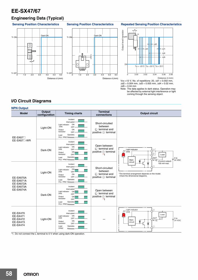
EE-SX47/67
58
Engineering Data (Typical)
I/O Circuit Diagrams
NPN Output
*1. Do not connect the L terminal to 0 V when using dark-ON operation.
Sensing Position Characteristics Sensing Position Characteristics Repeated Sensing Position Characteristics
Model Output configuration Timing charts Terminal
connections Output circuit
EE-SX67@EE-SX67@-WR
Light-ON
Short-circuited between
terminal and positive terminal
Dark-ON
Open between terminal and
positive terminal *1
EE-SX670AEE-SX671AEE-SX672AEE-SX673AEE-SX674A
Light-ON
Short-circuited between
terminal and positive terminal
Dark-ON
Open between terminal and
positive terminal *1
EE-SX470EE-SX471EE-SX472EE-SX473EE-SX474
Light-ON ---
Tr ON
Tr OFF0 1.0 2.0 3.0 4.0 5.0 6.0
Distance d (mm)
Dark-ON
d
Tr ON
Tr OFF0 1.0 2.0 3.0 4.0 5.0 6.0
Distance d (mm)
Dark-ON
d
d
OFF
ON
0 3.00 3.02 3.04 3.06 3.08
Out
put l
evel
tran
sist
or
Distance d (mm)
Ta = −25°C Ta = 55°C Ta = 25°C
Δd3 Δd1
Δd2
Δd4
Δd5
Vcc =12 V, No. of repetitions: 20, Δd1 = 0.002 mm, Δd2 = 0.004 mm, Δd3 = 0.005 mm, Δd4 = 0.02 mm, Δd5 = 0.04 mmNote: The data applies to dark status. Operation may
be affected by external light interference or light coming through the sensing object.
Incident
Interrupted
ON
OFF
ON
OFF
Operates
Releases
Light indicator (red)
Output transistor
Load (e.g., relay)
L
5 to 24 VDC(Control output)
100 mA max.
Load
Main circuit
L
OUTIC
Light indicator(red)
*The terminal arrangement depends on the model. Check the dimensional diagrams.
*
Incident
Interrupted
ON
OFF
ON
OFF
Operates
Releases
Light indicator(red)
Output transistor
Load(e.g., relay)
L
Incident
Interrupted
ON
OFF
ON
OFF
Operates
Releases
Light indicator(red)
Output transistor
Load(e.g., relay)
L
Incident
Interrupted
ON
OFF
ON
OFF
Operates
Releases
Light indicator(red)
Output transistor
Load (e.g., relay)
L
Incident
Interrupted
ON
OFF
ON
OFF
Operates
Releases
Light indicator(red)
Outputtransistor
Load (relay)
5 to 24 VDCIC
OUT
Light indicator(red)
Load
Main circuit

EE-SX47/67
59
PNP Output
*1. Do not connect the L terminal to 0 V when using dark-ON operation.
Safety PrecautionsRefer to Warranty and Limitations of Liability.
This product is not designed or rated for ensuring safety of persons either directly or indirectly.Do not use it for such purposes.
● Operating EnvironmentThese Photomicrosensors have an IP50 (conforms to IEC) enclosure and do not have a water-proof or dust-proof structure. Therefore, do not use them in applications in which the sensor will be subjected to splashes from water, oil, or any other liquid. Liquid entering the Sensor may result in malfunction.
Make sure that this product is used within the rated ambient environment conditions.● Installation• When direct soldering to the terminals, use the following guidelines.
Soldering Conditions
• The terminal base uses a polycarbonate resin, which could be deformed by excessive soldering heat, resulting in damage to the product's functionality.
● Lot Number and Model Number LegendIn the following diagrams, 376d indicates the lot number and factory where the product was manufactured. Do not include this code with the model number when ordering.
Model Output configuration Timing charts Terminal
connections Output circuit
EE-SX67@PEE-SX67@P-WR
Light-ON
Short-circuited between
terminal and positive terminal
Dark-ON
Open between terminal and
positive terminal *1
EE-SX670REE-SX671REE-SX672REE-SX673REE-SX674R
Light-ON
Short-circuited between
terminal and positive terminal
Dark-ON
Open between terminal and
positive terminal *1
EE-SX470PEE-SX471PEE-SX472PEE-SX473PEE-SX474P
Light-ON ---
Incident
Interrupted
ON
OFF
ON
OFF
Operates
Releases
Light indicator(red)
Outputtransistor
Load(relay)
L
5 to 24 VDC
Load
Maincircuit
L
OUTIC
Light indicator(red)
*
*The terminal arrangement depends on the model. Check the dimensional diagrams.
Incident
Interrupted
ON
OFF
ON
OFF
Operates
Releases
Light indicator(red)
Outputtransistor
Load(relay)
L
Incident
Interrupted
ON
OFF
ON
OFF
Operates
Releases
Light indicator(red)
Output transistor
Load(e.g., relay)
L
Incident
Interrupted
ON
OFF
ON
OFF
Operates
Releases
Light indicator(red)
Outputtransistor
Load(e.g., relay)
L
Incident
Interrupted
ON
OFF
ON
OFF
Operates
Releases
Light indicator(red)
Outputtransistor
Load(relay)
5 to 24 VDC
Load
Main circuit
OUTIC
Light indicator (red)
WARNING
Precautions for Safe Use
Precautions for Correct Use
Item Temper-ature
Permissibletime Remarks
Soldering iron
350°Cmax. 3 s max.
The portion between the base of the terminals and the position 1.5 mm from the terminal base must not be soldered.
EE-SX670
Lot number and factory code
Model number
376d
EE-SX@70@

EE-SX47/67
60
(Unit: mm)
Dimensions Tolerance class IT16 applies to dimensions in this datasheet unless otherwise specified.
Sensors
19
13.4
5
13.8
9
13.2
6.2
5.5
3.8
2.54
Indicator window
25.4
19
6.95
Four, R16.4
0.8
2
0.3 0.7
Optical axis
32 41
Two, 3.2 dia. holes
Two, 3.8 dia. holes
8.4
EE-SX670/670PEE-SX670A/670REE-SX470/470P
Terminal Arrangement
* Pin 2 is not used for the EE-SX470.
(1) Vcc
(2) L L*
(3) OUT OUTPUT
(4) GND (0 V)
19
19
26.2
Four, R2
Two, 3.2 dia. holes
Four, R1
13.4
13
13.4
5
13
9
2.54
3
14.5
6.2
8.3
7.2
3.2
3
3.8
9
3.6
2.1
0.76.2
0.6
0.3
2
7.2
15.5
0.8
Optical axis
Indicator window
6.95
6.35
32 41
EE-SX671/671PEE-SX671A/671REE-SX471/471P
Terminal Arrangement
* Pin 2 is not used for the EE-SX471.
(1) Vcc
(2) L L*
(3) OUT OUTPUT
(4) GND (0 V)
19
Four, R1
Four, R1.6
13.4
5
13.7
3
7
13
2.54
22.2
6.2
9
3
12.626 6.4
6.3
3.8
8.4
2.5
2
13
6.2
6.3
0.8
2.5
4.3
Optical axis
Indicator window
0.3 0.72 31 4
EE-SX672/672PEE-SX672A/672REE-SX472/472P
Terminal Arrangement
* Pin 2 is not used for the EE-SX472.
(1) Vcc
(2) L L*
(3) OUT OUTPUT
(4) GND (0 V)
13.4
5
7
2.54
22.2
6.2
9
12.8
6.3
3.5(6.65)
14.4
3.8
2.8
4.9
2
0.8
Optical axis
Indicator window
0.3 0.732 41
Two, 3.2 dia. holesTwo, R1
EE-SX673/673PEE-SX673A/673REE-SX473/473P
Terminal Arrangement
* Pin 2 is not used for the EE-SX473.
(1) Vcc
(2) L L*
(3) OUT OUTPUT
(4) GND (0 V)

EE-SX47/67
61
7 Two, 3.5 dia. holesTwo, R1
13.6
513
2.54
3
21.5
6.2
(9.3)
6.2
6.95
7
3
3.8
(2.9)
2.1
0.7
0.6
0.3
2
2.6
15.5
0.8 0.1
Optical axis
Indicator window
32 41
EE-SX674/674PEE-SX674A/674REE-SX474/474P Terminal Arrangement
* Pin 2 is not used for the EE-SX474.
(1) Vcc
(2) L L*
(3) OUT OUTPUT
(4) GND (0 V)
5
13.4
16.7
4
26
38.4
2.5
(R)(R)
3.2
3.7
0.8Optical axis
Sensing window
Optical axis
Indicator window2
13
19.5
0.30.7
6.3
6
10
6.35
2 31 4
16.713
2.54
22.2
9
6.23.8
EE-SX675/675P
Terminal Arrangement
(1) Vcc
(2) L L
(3) OUT OUTPUT
(4) GND (0 V)
Two, 3.5 dia. holes
2.5
5
8.43
3.8
2.5
6.3513.2
0.8
9
7
0.3
3.3
2
0.7
13.6
7
2.5432 41
13.7
7
13.4
9
22.2
6.2
Optical axis
Optical axis
Indicator window
Sensing window
EE-SX676/676P
Terminal Arrangement
(1) Vcc
(2) L L
(3) OUT OUTPUT
(4) GND (0 V)
Two, 3.5 dia. holes
2.5
7
13.4
22.2
6.2 3.8
13.26.35
70.8
2
13.6
9
7
3.3
0.3
0.7
13.7
5
2.5
8.43
9
2.5432 41
Optical axis
Optical axis
Indicator window
Sensing window
EE-SX677/677P
Terminal Arrangement
(1) Vcc
(2) L L
(3) OUT OUTPUT
(4) GND (0 V)

EE-SX47/67
62
R1
19
25.4
3.2 dia.
6.35
6.95
26.2
2
2.5
13.8
3.8 dia.
Optical axis
Indicator window Robot cable of 2.8 dia., 4 cores, (0.15 mm2 with 0.8 mm dia. insulator);Standard length: 1 m
Optical axis
4.6 dia.
11
8.4
911.2
13.4
5 0.8
5.5
3
2
Sensing window
EE-SX670-WR/670P-WR
Terminal Arrangement
Brown Vcc
Pink L
Blue GND (0 V)
Black OUTPUT
26.2
19
6.95
18.73
13.4
13.45
3
9
9
3.6
4.6 dia.
6.35
0.8
2
6.22.8
3.2
R3.5
R1
15.5
3.2 dia.19
7.2
2
Indicator window
Optical axis
Optical axis
Robot cable of 2.8 dia., 4 cores, (0.15 mm2 with 0.8 mm dia. insulator);Standard length: 1 m
Sensing window
EE-SX671-WR/671P-WR
Terminal Arrangement
Brown Vcc
Pink L
Blue GND (0 V)
Black OUTPUT
13.7
7
12.6
13.45
3
9
2.5
8.426.2
2
26
19
4.6 dia.
10.3
6.2
13
6.35
0.8
2
4.32.5
R1.6
R13
Indicator window
Optical axis
Optical axis
Robot cable of 2.8 dia., 4 cores, (0.15 mm2 with 0.8 mm dia. insulator);Standard length: 1 m
Sensing window
EE-SX672-WR/672P-WR
Terminal Arrangement
Brown Vcc
Pink L
Blue GND (0 V)
Black OUTPUT
(6.65)
6.3
14.4
8.9
92
4.6 dia.
2 dia.
3.2 dia.
26.2
2
12.8
2.8
3.5
R1
0.813.4
5
7
Indicator window
Optical axis
Optical axis
Robot cable of 2.8 dia., 4 cores, (0.15 mm2 with 0.8 mm dia. insulator);Standard length: 1 m
Sensing window
EE-SX673-WR/673P-WR
Terminal Arrangement
Brown Vcc
Pink L
Blue GND (0 V)
Black OUTPUT

EE-SX47/67
63
EE-SX674-WR/674P-WR
Terminal Arrangement
Brown Vcc
Pink L
Blue GND(0V)
Black OUTPUT
7
3.5 dia. 7R1
25.7
6.95
3
3
2
13.6
5
(2.9)
9
6.2
4.6 dia.
2.8
2
0.8
2.6
15.5
7
Optical axis
Optical axis
Indicator window
Robot cable of 2.8 dia., 4 cores, (0.15 mm2 with 0.8 mm dia. insulator);Standard length: 1 m
Sensing window
2
3.7
(R)
(R)
6 3.2
13
10.3
2
19.5
16.7
13.4
4.6 dia.
326.2 8.4
9
2.5
13.4
5
10
4
6.35 26
0.8
Optical axis
Optical axis
Indicator window
Robot cable of 2.8 dia., 4 cores, (0.15 mm2 with 0.8 mm dia. insulator);Standard length: 1 m
Sensing window
EE-SX675-WR/675P-WR
Terminal Arrangement
Brown Vcc
Pink L
Blue GND(0V)
Black OUTPUT
3
4.6 dia.
2.5
8.4
2
26.2
9
13.4
5
13.7
7
6.4
13.2
7
20.8
9
713
3.3
3.5 dia.
2.5
4
Optical axis
Optical axis
Indicator window
Robot cable of 2.8 dia., 4 cores, (0.15 mm2 with 0.8 mm dia. insulator);Standard length: 1 m
Sensing window
EE-SX676-WR/676P-WR
Terminal Arrangement
Brown Vcc
Pink L
Blue GND(0V)
Black OUTPUT
3.3
4
7
9
7
6.413.2
13
3.5 2
26.2 8.4 2.5
9
13.4
5
13.7
7
2.5
3
4.6 dia.
2
0.8
Optical axis
Optical axis
Indicator window
Robot cable of 2.8 dia., 4 cores, (0.15 mm2 with 0.8 mm dia. insulator);Standard length: 1 m
Sensing window
EE-SX677-WR/677P-WR
Terminal Arrangement
Brown Vcc
Pink L
Blue GND(0V)
Black OUTPUT

MEMO
64

65
Slot-type Photomicrosensor with Connector (Modulated)
EE-SPX74/84Photomicrosensor with light modulation for reduced externallight interference and a connector for easy maintenance.• Built-in connectors
• Select from four easy-to-use shapes for efficient space utilization.
• Connectors with locks for safety against vibration.
• Convenient mounting method using M3 screws.• Wide operating voltage range: 5 to 24 VDC
Be sure to read Safety Precautions on page 68.
Ordering Information
Sensors
Accessories (Order Separately)Connector with Cable
* Refer to Accessories for details.
Appearance Sensing method Sensing distance Output type Output configuration Model
Through-beam type (with slot) NPN output
Dark-ON EE-SPX740
Light-ON EE-SPX840
Dark-ON EE-SPX742
Light-ON EE-SPX842
Dark-ON EE-SPX743
Light-ON EE-SPX843
Dark-ON EE-SPX741
Light-ON EE-SPX841
Infrared light
3.6 mm (slot width)
5 mm (slot width)
Type Cable length ModelConnector 1 m EE-1013

EE-SPX74/84
66
Ratings and Specifications
ItemModels
EE-SPX740, EE-SPX840EE-SPX742, EE-SPX842EE-SPX743, EE-SPX843
EE-SPX741EE-SPX841
Sensing distance 3.6 mm (slot width) 5 mm (slot width) *1. The indicator is a GaAlAs red LED (peak wavelength: 660 nm).
*2. The response frequency was measured by detecting the following rotating disk.
Sensing object Opaque: 1 × 0.5mm min. Opaque: 2 × 0.8 mm min.
Differential distance 0.05 mm max.
Light source GaAs infrared LED (pulse lighting) with a peak wavelength of 940 nm
Indicator *1 Light indicator (red)
Supply voltage 5 to 24 VDC ±10%, ripple (p-p): 5% max.
Current consumption Average: 15 mA max.; Peak: 50 mA max.
Control output
NPN voltage output:Load power supply voltage: 5 to 24 VDC Load current: 50 mA max.
OFF current: 0.5 mA max.50 mA load current with a residual voltage of 1.0 V max.10 mA load current with a residual voltage of 0.4 V max.
Response frequency *2 500 Hz min.
Ambient illumination 3,000 lx max. with incandescent light or sunlight on the surface of the receiver
Ambient temperature range
Operating: −10 to +55°CStorage: −25 to +65°C
Ambient humidity range Operating: 5% to 85%Storage: 5% to 95%
Vibration resistance Destruction: 10 to 55 Hz, 1.5-mm double amplitude for 2 h each in X, Y, and Z directions
Shock resistance Destruction: 500 m/s2 for 3 times each in X, Y, and Z directions
Degree of protection IEC IP50
Connecting method Special connector
Weight Approx. 2.4 g
MaterialCase
PolycarbonateHolder
2 mm2 mm2 mm
Disk
Disk
Disk
EE-SPX741/841
EE-SPX742/842EE-SPX743/843
EE-SPX740/840

EE-SPX74/84
67
Engineering Data (Typical)
Sensing Position Characteristics
EE-SPX740/742/743
EE-SPX741
0 1 2 3 4 5 6
Tr ON
Tr OFF
d
Insertion direction
Insertion direction
d
Dark-ON
Distance d (mm)0 1 2 3 4 5 6
Tr ON
Tr OFF
d
Dark-ON
Distance d (mm)
Insertion direction
Tr ON
Tr OFF0 1 2 3 4 5 6
d
Dark-ON
Distance d (mm)
Insertiondirection
Tr ON
Tr OFF
d
Dark-ON
0 1 2 3 4 5 6
Distance d (mm)
Insertiondirection

EE-SPX74/84
68
I/O Circuit Diagrams
NPN Output
Safety Precautions
Refer to Warranty and Limitations of Liability.
This product is not designed or rated for ensuring safety of persons either directly or indirectly.Do not use it for such purposes.
Make sure that this product is used within the rated ambient environment conditions.● Design
Cable Extension• When extending the cable, use an extension cable with conductors
having a total cross-section area of 0.15 mm2. The total cable length must be 4 m maximum.
• To use a cable length longer than 4 m, attach a capacitor with a capacitance of approximately 10 μF to the wires as shown below. The distance between the terminal and the capacitor must be within 4 m. (Use a capacitor with a dielectric strength that is at least twice the Sensor's power supply voltage.)
• Make sure the total length of the power cable connected to the product is less than 10 m even if a capacitor is inserted.
Effects of Inductive NoiseWhen there is inductive noise in the Sensor mounting frame (metal), the output of the Sensor may be affected. In this case, ensure that there is no electrical potential difference between the Sensor 0-V terminal and the Sensor mounting frame, or attach a 0.47 μF capacitor between the 0-V terminal and the frame.
Model Output configuration Timing charts Output circuit
EE-SPX740EE-SPX741EE-SPX742EE-SPX743
Dark-ON
EE-SPX840EE-SPX841EE-SPX842EE-SPX843
Light-ON
Incident
Interrupted
ON
OFF
ON
OFF
Operates
Releases
H
L
Light indicator(red)
Outputtransistor
Load 1(relay)
Output 2
Light indicator(red)
1.5 to 3 mA Load 1
Load 2
Maincircuit
OUT
∗
* Voltage output (when the sensor is connected to a transistor circuit)
5 to 24 VDC
Incident
Interrupted
ON
OFF
ON
OFF
Operates
Releases
H
L
Light indicator(red)
Outputtransistor
Load 1(relay)
Load 2
WARNING Precautions for Correct Use
5 to 24 VDC
0 V
4 m max. Extension cable
OUT A capacitance of10 μF min.
PowersupplySensor
Mounting frame
0.47 μF
0 V
5 to 24 VDC

EE-SPX74/84
69
(Unit: mm)
Dimensions Tolerance class IT16 applies to dimensions in this datasheet unless otherwise specified.
Sensors
Optical axis (0.5-mm wide)
Optical axis (1-mm wide)
6.6 Two, 3.5 dia. holes3
21.2
15.6 Indicator window (red)3
3.4
19 2513.8 3.6
2.5
(2)
(3)
(1)
5
15.2
7 7.4
5.3
EE-SPX740EE-SPX840
Terminal Arrangement
(1) − GND (0 V)
(2) OUT OUTPUT
(3) + Vcc
2.5
R3.2R3.2
Indicator window(red)
(2)
(3)
(1)
5
3
5.38.3
Optical axis (1-mm wide)
6.6
132.5
Optical axis (0.5-mm wide)See note.
3.6
2.5
2 dia.C0.5
21.2
15.6
63.5 dia. hole
6.5
2.6
6
7
EE-SPX742EE-SPX842
Terminal Arrangement
(1) − GND (0 V)
(2) OUT OUTPUT
(3) + Vcc
Note: The lug is used to prevent turning and to indicate the optical axis. When installing, make a fixed hole of 2.1 to 2.3 mm dia.
EE-SPX743EE-SPX843
2.5
R3.2
Indicator window(red)
5
3
5.38.3
6.6
132.5
Optical axis (0.5-mm wide)
3.6
2.5
2 dia.
21.2
15.6
6 3.5 dia. hole
6.5
2.6
6
7
Optical axis (1-mm wide)
C0.5See note.
(3)
(2)
(1)
Terminal Arrangement
(1) − GND (0 V)
(2) OUT OUTPUT
(3) + Vcc
Note: The lug is used to prevent turning and to indicate the optical axis. When installing, make a fixed hole of 2.1 to 2.3 mm dia.

EE-SPX74/84
70
Accessories (Connector with Cable)
EE-SPX741EE-SPX841
13.3 52.5
12.52.5
3
5.5
Indicator window(red)
3
3.2
Four, R2
27.2
Two, 3.2 dia. holes
20
3.6
9
20 14.4
15.512.6
6.35
Optical axis (2-mm wide)
Optical axis (0.8-mm wide)
7.2
6.9514.5
5.9 6.6
15.4
5
(3)
(2)
(1)
Terminal Arrangement
(1) − GND (0 V)
(2) OUT OUTPUT
(3) + Vcc
EE-1013
5.7
2.5
7.75 20
XHP-3 (JST Mfg.)
1,000 16±2 7±1
9.8
Vinyl-insulated round cable of 2.9 dia., with 3 cores(0.15 mm2 with 0.9-dia. insulator); Standard length: 1 m(3)
(2)
(1)
Terminal Arrangement
(1) Blue GND (0 V)
(2) Black OUTPUT
(3) Brown Vcc

71
Slot-type Photomicrosensor with Cable
EE-SPX-WPhotomicrosensor with built-in amplifier and attached cable reduces external light interference.• Light modulation effectively reduces external light interference.• Wide operation voltage range: 5 to 24 VDC
• Easy operation monitoring with bright light indicator.
Be sure to read Safety Precautions on page 73.
Ordering Information
* These models (EE-SPX305/405-W2A only) are not conformed to CE standards.
Appearance Sensing method
Sensing distance (slot width)
Output type
Output configuration
Cable length Model
Through-beam type
NPN output
Dark-ON
1 m
EE-SPX302-W2A 1M
Light-ON EE-SPX402-W2A 1M
Dark-ON EE-SPX304-W2A 1M
Light-ON EE-SPX404-W2A 1M
Dark-ON EE-SPX306-W2A 1M
Light-ON EE-SPX406-W2A 1M
Dark-ON EE-SPX305-W2A 1M*
Light-ON EE-SPX405-W2A 1M*
Infrared light
3.6 mm
3.6 mm
3.6 mm
5 mm

EE-SPX-W
72
Ratings and Specifications
I/O Circuit Diagrams
NPN Output
Item
Models EE-SPX302-W2A, EE-SPX402-W2AEE-SPX304-W2A, EE-SPX404-W2AEE-SPX306-W2A, EE-SPX406-W2A
EE-SPX305-W2AEE-SPX405-W2A
Sensing distance 3.6 mm (slot width) 5 mm (slot width) *1. The indicator is a GaP red LED (peak wavelength: 700 nm).
*2. The response frequency was measured by detecting the following rotating disk.
Sensing object Opaque: 1 × 0.5 mm min. Opaque: 2 × 0.8 mm min.
Differential distance 0.05 mm max.
Light source GaAs infrared LED (pulse lighting) with a peak wavelength of 940 nm
Indicator *1 Light indicator (red)
Supply voltage 5 to 24 VDC ±10%, ripple (p-p): 5% max.
Current consumption Average: 15 mA max.; Peak: 50 mA max.
Control output
NPN voltage output: Load power supply voltage: 5 to 24 VDCLoad current: 80 mA max.
OFF current: 0.5 mA max.80 mA load current with a residual voltage of 1.0 V max.10 mA load current with a residual voltage of 0.4 V max.
Response frequency *2 500 Hz min.
Ambient illumination 3,000 lx max. with incandescent light or sunlight on the surface of the receiver
Ambient temperature range
Operating: −10 to +55°CStorage: −25 to +65°C
Ambient humidity range Operating: 5% to 85%Storage: 5% to 95%
Vibration resistance Destruction: 10 to 55 Hz, 1.5-mm double amplitude for 2 h each in X, Y, and Z directions
Shock resistance Destruction: 500 m/s2 for 3 times each in X, Y, and Z directions
Degree of protection IEC IP50
Connecting method Pre-wired (standard cable length: 1 m)
Weight 18.5 g
MaterialCase
PolycarbonateHolder
Model Output configuration Timing charts Output circuit
EE-SPX402-W2AEE-SPX404-W2AEE-SPX405-W2AEE-SPX406-W2A
Light-ON
EE-SPX302-W2AEE-SPX304-W2AEE-SPX305-W2AEE-SPX306-W2A
Dark-ON
2 mm2 mm2 mm
Disk
Disk
Disk
EE-SPX305-W2A
EE-SPX302-W2A EE-SPX306-W2A
Incident
Interrupted
ON
OFF
ON
OFF
Operates
Releases
H
L
Light indicator(red)
Output transistor
Load 1(relay)
Load 25 to 24 VDC
Light indicator (red)
1.5 to 3 mA Load 1
Load 2
Maincircuit
Black
Blue
Brown
∗
* Voltage output (when the sensor is connected to a transistor circuit)
Incident
Interrupted
ON
OFF
ON
OFF
Operates
Releases
H
L
Light indicator(red)
Outputtransistor
Load 1(relay)
Load 2

EE-SPX-W
73
Engineering Data (Typical)
Safety Precautions
Refer to Warranty and Limitations of Liability.
This product is not designed or rated for ensuring safety of persons either directly or indirectly.Do not use it for such purposes.
Make sure that this product is used within the rated ambient environment conditions.● Wiring• When extending the cable, use an extension cable with conductors
having a total cross-section area of 0.3 mm2. The total cable length must be 2 m maximum.
• To use a cable length longer than 2 m, attach a capacitor with a capacitance of approximately 10 μF to the wires as shown below. The distance between the terminal and the capacitor must be within 2 m. (Use a capacitor with a dielectric strength that is at least twice the Sensor's power supply voltage.)
• Make sure the total length of the power cable connected to the product is less than 10 m even if a capacitor is inserted.
Sensing Position Characteristics
EE-SPX302-W2AEE-SPX304-W2AEE-SPX306-W2A
EE-SPX302-W2AEE-SPX304-W2AEE-SPX306-W2A
EE-SPX305-W2A EE-SPX305-W2A
0 1 2 3 4 5 6
Tr ON
Tr OFF
d
d
Dark-ON
Distance d (mm)
0 1 2 3 4 5 6
Tr ON
Tr OFF
d
Dark-ON
Distance d (mm)
Tr ON
Tr OFF0 1 2 3 4 5 6
EE-SPX305-W2A
d
Dark-ON
Distance d (mm)
Tr ON
Tr OFF
d
Dark-ON
0 1 2 3 4 5 6
Distance d (mm)
WARNING Precautions for Correct Use
+
−
A capacitance of10 μF min.
5 to 24 VDC
2 m max.
0 V
+
−
Extension cable

EE-SPX-W
74
(Unit: mm)
Dimensions Tolerance class IT16 applies to dimensions in this datasheet unless otherwise specified.
∗
Optical axis(0.5-mm wide)
Optical axis(1-mm wide)
See note.2.5
2.5
13 3.6
C0.52 dia.
6.6 Indicator window
R3.2
R3.27 dia.
6
7
15.6 33.5 dia.hole
6.5
21.2 8
1,000
* Vinyl-insulated round cable of 3.5 dia., 3 cores, (0.14 mm2 with 1.0-dia. insulator); Standard length: 1 m
Note: The lug is used to prevent turning and to indicate the optical axis. When installing, make a fixed hole of 2.1 to 2.3 mm dia.
EE-SPX302-W2AEE-SPX402-W2A
∗
Optical axis(0.5-mm wide)
Optical axis (1-mm wide)See note.
2.52.5
13 3.6
C0.52 dia.
6.6 Indicator window
R3.2
R3.27 dia.
6
6
7
15.6 33.5 dia. hole
6.5
21.2 8
1,000
Note: The lug is used to prevent turning and to indicate the optical axis. When installing, make a fixed hole of 2.1 to 2.3 mm dia.
* Vinyl-insulated round cable of 3.5 dia., 3 cores, (0.14 mm2 with 1.0-dia. insulator); Standard length: 1 m
EE-SPX304-W2AEE-SPX404-W2A
3.6
6.6Two, 3.5 dia. holes
Optical axis(0.5-mm wide)
7.4
7
1.5 max.
Indicator window
6 8
21.2 1,000
Optical axis(1-mm wide)
15.6 3
13.8 19 25
∗
* Vinyl-insulated round cable of 3.5 dia., 3 cores, (0.14 mm2 with 1.0-dia. insulator); Standard length: 1 m
Indicator window
EE-SPX306-W2AEE-SPX406-W2A
∗
14.5 1,0008
6.95
7.212.7
15.5
6.35Optical axis window (2 × 0.8)
3.6 3.29
20
Two, 3.2 dia.
14.4 20 27.25
Four, R2Indicator window
* Vinyl-insulated round cable of 3.5 dia., 3 cores, (0.14 mm2 with 1.0-dia. insulator); Standard length: 1 m
7 dia.
EE-SPX305-W2AEE-SPX405-W2A

75
Broad Slot-type Photomicrosensor
EE-SPX303N/403NA Wide Slot Width of 13 mm and Superior Resistance to Light Interference and Noise.• Noise resistance equivalent to photomicrosensors with built-in amplifiers.
• Resistance to common noise at least 30 times that of previous models.
• Resistance to inverter noise at least 10 times that of previous models.• Reverse polarity protection built in.
Be sure to read Safety Precautions on page 77.
Ordering Information
Sensors
Accessories (Order Separately)
* Refer to Accessories for details.
Appearance Sensing method Sensing distance(slot width) Output type Output
configuration Model
Through-beam type(with slot) NPN output
Dark-ON EE-SPX303N
Light-ON EE-SPX403N
Type Cable length ModelConnector EE-1001
EE-1009
Connector with Cable
1 mEE-1006 EE-1010
2 mEE-1006 EE-1010
Connector with Robot Cable
1 m EE-1010-R2 m EE-1010-R
NPN/PNP Conversion Connector 0.46 m (total length) EE-2002
Infrared light
13 mm(slot width)

EE-SPX303N/403N
76
Ratings and Specifications
Engineering Data (Typical)
Sensing Position Characteristics
EE-SPX303N
Item Models EE-SPX303N, EE-SPX403N
Sensing distance 13 mm (slot width)
Sensing object Opaque: 2.2 × 0.5 mm min.
Differential distance 0.05 mm max.
Light source Infrared LED (pulse lighting) with a peak wavelength of 940 nm
Indicator Light indicator (red)
Supply voltage 12 to 24 VDC ±10%, ripple (p-p): 5% max.
Current consumption 15 mA max.
Control output
NPN voltage output:Load power supply voltage: 12 to 24 VDCLoad current: 80 mA max.
OFF current: 0.5 mA max.80 mA load current with a residual voltage of 2.0 V max.10 mA load current with a residual voltage of 1.0 V max.
Protection circuits Power supply reverse polarity protection, Output reverse polarity protection
Response frequency * 100 Hz min.
Ambient illumination 3,000 lx max. with incandescent light or sunlight on the surface of the receiver.
Ambient temperature range
Operating: −10 to +55°CStorage: −25 to +65°C
Ambient humidity range Operating: 5% to 85%Storage: 5% to 95%
Vibration resistance Destruction: 10 to 55 Hz, 1.5-mm double amplitude for 2 h each in X, Y, and Z directions
Shock resistance Destruction: 500 m/s2 for 3 times each in X, Y, and Z directions
Degree of protection IEC IP50
Connecting method Special connector (soldering not possible)
Weight Approx. 4 g
Material Polycarbonate
* The response frequency was measured by detecting the following rotating disk.
2 mm
Disk
2 mm2 mm
0 1 2 3 4 5 6
Distance d (mm)
Tr ON
Tr OFF
Dark-ON
d
0 1 2 3 4 5 6
Distance d (mm)
Tr ON
Tr OFF
Dark-ON
d

EE-SPX303N/403N
77
I/O Circuit Diagrams
NPN Output
Safety Precautions
Refer to Warranty and Limitations of Liability.
This product is not designed or rated for ensuring safety of persons either directly or indirectly.Do not use it for such purposes.
Make sure that this product is used within the rated ambient environment conditions.● Wiring• Connection is made using a connector. Do not solder to the pins
(leads). The pins (leads) are soldered to the internal board of the Sensor. Therefore, direct soldering of the pins (leads) may result in an internal disconnection causing malfunction.
• When extending the cable, use an extension cable with conductors having a total cross-section area of 0.3 mm2. The total cable length must be 2 m maximum.
• To use a cable length longer than 2 m, attach a capacitor with a capacitance of approximately 10 μF to the wires as shown below. The distance between the terminal and the capacitor must be within 2 m. (Use a capacitor with a dielectric strength that is at least twice the Sensor's power supply voltage.)
• Make sure the total length of the power cable connected to the product is less than 10 m even if a capacitor is inserted.
Model Output configuration Timing charts Output circuit
EE-SPX403N Light-ON
EE-SPX303N Dark-ON
Incident
Interrupted
ON
OFF
ON
OFF
Operates
Releases
H
L
Light indicator(red)
Outputtransistor
Load 1(relay)
Load 2
lC
Light indicator (red) 1.5 to
3 mA Load 1
Load 2
Maincircuit
OUT
∗
* Voltage output (when the sensor is connected to a transistor circuit)
12 to 24 VDCIncident
Interrupted
ON
OFF
ON
OFF
Operates
Releases
H
L
Light indicator(red)
Outputtransistor
Load 1(relay)
Load 2
WARNING Precautions for Correct Use
OUT
Extension cable
A capacitance of10 μF min.
+
−
12 to 24 VDC
0 V
2 m max.

EE-SPX303N/403N
78
(Unit: mm)
Dimensions Tolerance class IT16 applies to dimensions in this datasheet unless otherwise specified.
Sensors
Accessories (Order Separately)* Refer to Accessories for details.
7.4
0.30.7
31
10
19
3.2
26
26
2-3.7
5.0813
19.5
2.54321
Four, R1.6
Indicator window
Sensing window (0.5 × 2.2)
EE-SPX303N, EE-SPX403N
Terminal Arrangement
(1) + Vcc
(2) OUT OUTPUT
(3) − GND (0 V)

79
Long-distance Through-beam Photomicrosensor
EE-SPW311/411Through-beam Photomicrosensor with a sensing distance as long as1 m.• Easy operation monitoring with bright light indicator.• Wide operating voltage range: 5 to 24 VDC
• Light modulation effectively reduces external light interference.
• Easy-to-wire connector assures ease of maintenance.
Be sure to read Safety Precautions on page 81.
Ordering Information
Sensors
* Both an EE-1006L Connector with Cable for the Emitter and an EE-1006D Connector with Cable for the Receiver are included with the Photomicrosensor.Refer to Accessories when using non-standard connectors, including Robot Cables and PNP Adapters.
Appearance Sensing method Sensing distance Output type Output configuration Model
Through-beamtype
NPNoutput
Dark-ON EE-SPW311
Light-ON EE-SPW411
Infrared light
1m

EE-SPW311/411
80
Ratings and Specifications
Engineering Data (Typical)
Item Models EE-SPW311, EE-SPW411
Sensing distance 1 m
*1. The indicator is a GaP red LED (peak wavelength: 700 nm).
*2. The response frequency was measured by detecting the following rotating disk.
Sensing object Opaque: 5 mm dia. min.
Directional angle 5 to 20°
Light source GaAs infrared LED (pulse lighting) with a peak wavelength of 940 nm
Indicator *1 Light indicator (red)
Supply voltage 5 (−5%) to 24 (+10%) VDC, ripple (p-p): 5% max.
Current consumption Emitter: 20 mA max., Receiver: 20 mA max.
Control output
NPN open collector:Load power supply voltage: 5 to 24 VDCLoad current: 100 mA max.OFF current: 0.5 mA max.100 mA load current with a residual voltage of 0.8 V max.10 mA load current with a residual voltage of 0.4 V max.
Response frequency *2 100 Hz min.
Ambient illumination 3,000 lx max. with incandescent light on the surface of the receiver
Ambient temperature range
Operating: −10 to +55°CStorage: −25 to +65°C
Ambient humidity range Operating: 5% to 85%Storage: 5% to 95%
Vibration resistanceDestruction: 200 to 2,000 Hz (peak acceleration: 100 m/s2)1.5-mm double amplitude for 2 h (4-min periods) each in X, Y, and Z directions
Shock resistance Destruction: 500 m/s2 for 3 times each in X, Y, and Z directions
Degree of protection IEC IP60
Connecting method Special connector (soldering not possible)
Weight (packaged) Approx. 8.8 g
MaterialCase Polybutylene phthalate (PBT)
Lens Polycarbonate
Accessories EE-1006L/D Connectors with Cables, Instruction Manual
Receiver Output Excess Gain Vs.
Sensing Distance Characteristics
Parallel Movement Characteristics
1 m
Optical axis
5 mm5 mm5 mm
1,000
500300
100
5030
10
53
1
0 0.2 0.4 0.6 0.8 1.0 1.2 1.4 1.6 1.8
Distance between sensors (m)
Rec
eive
r ou
tput
exc
ess
gain
(m
ultip
le)
0.2 0.4 0.6 0.8 1 1.2 1.4 1.6 1.8
Distance X
Distance X (m)
Distance Y
140
120
100
80
60
40
20
0
Dis
tanc
e Y
(m
m)

EE-SPW311/411
81
I/O Circuit Diagrams
NPN Output
Safety Precautions
Refer to Warranty and Limitations of Liability.
This product is not designed or rated for ensuring safety of persons either directly or indirectly.Do not use it for such purposes.
Make sure that this product is used within the rated ambient environment conditions.● Wiring• Connection is made using a connector. Do not solder to the pins
(leads).• When extending the cable, use an extension cable with conductors
having a total cross-section area of 0.3 mm2. The total cable length must be less than 10 m.
● Axis Adjustment(1)Tentatively mount the emitter and receiver so that the center of
each lens is in a single line.
(2)Turn ON the emitter and receiver after making sure that they have been wired correctly. When power is turned ON, the light indicator on the receiver will light. Make sure that the light indicator is OFF when an object intercepts the optical axis and that the light indicator lights again when the object is removed.
(3)Fix the position of the receiver (or emitter) securely, move the emitter (or receiver) horizontally and vertically to check the range in which the operation indicator is lit. Then locate the emitter (or receiver) in the center of the range and fix the position securely.
Model Output configuration Timing charts Output circuit
EE-SPW411 Light-ON
EE-SPW311 Dark-ON
WARNING
Incident
Interrupted
ON
OFF
ON
OFF
Operates
Releases
Light indicator(red)
Outputtransistor
Load 1(relay)
Light indicator(red)
Load
Maincircuit
OUT5 to 24 VDC
Incident
Interrupted
ON
OFF
ON
OFF
Operates
Releases
Light indicator(red)
Output transistor
Load 1(relay)
Precautions for Correct Use
Top view
Side view

EE-SPW311/411
82
(Unit: mm)
Dimensions Tolerance class IT16 applies to dimensions in this datasheet unless otherwise specified.
Sensors
Accessories (Included)
* Refer to Accessories for details.
EE-SPW311EE-SPW411
7.4
2.54
Two, 3.2 dia. holes
0.3
0.7
Sensingwindow
Sensingwindow
0.6
8
25.4
7.4
6.2
27
5.5
19
1925.4
13.4
14.1
15.1
2.54
Two, 3.2 dia. holes
0.3
0.7
Indicator window5 dia. 5 dia.
0.6
8
1.5
27
6.2
15.1
5.5
19
13.4
19
14.1
(1) (2) (3) (1) (2) (3)
Two, 3.8 dia. holes
Two, 3.8 dia. holes
Emitter (EE-SPWL@11) Receiver (EE-SPWD@11)
Terminal Arrangement
(1) + Vcc
(2) --- Vacant
(3) − GND (0 V)
Terminal Arrangement
(1) + Vcc
(2) OUT OUTPUT
(3) − GND (0 V)
Connector with Cable for Emitter EE-1006L
20 2,000
Vinyl-insulated round cable of 4 dia., 2 cores,(0.2 mm2 with 1.1-dia. insulator)
0.616.2
5.3
11.82.54
(1)(2)(3)(4)
(1)(2)(3)(4)
(1) Brown +
(4) Blue −
Connector with Cable for ReceiverEE-1006D
Vinyl-insulated round cable of 4 dia., 3 cores,(0.2 mm2 with 1.1-dia. insulator)
0.6
11.82.54
16.2 20 2,000
5.3
(1)(2)(3)(4)
(1)(2)(3)(4)
(1) Brown +
(3) Black OUT
(4) Blue −
Note: These cables can also be ordered separately.

83
Pre-wired Photomicrosensor with Amplifier and Cable
EE-SPW321/421Compact, Thin-profile Photomicrosensor with special amplifier.• Slim amplifier (50 × 7.5 × 12 mm) can be handled like a cable.• Provided with two operation indicators, enabling monitoring from the amplifier
housing and sensor head.
• Simple wiring with a 3-conductor cable.• Wide operating voltage range: 12 to 24 VDC
Be sure to read Safety Precautions on page 86.
Ordering Information
Sensing method Sensing distance Output type Output configuration Cable length Cable length from emitter to
amplifier Model
Through-beam type
NPNoutput
Dark-ON2 m
0.5 m EE-SPW3211 m EE-SPW321-A
Light-ON0.5 m EE-SPW4211 m EE-SPW421-A
300 mm

EE-SPW321/421
84
Ratings and Specifications
*1. Refer to Receiver Output Vs. Sensing Distance Characteristics on the next page.*2. Detection of objects up to 0.5 mm wide is possible by using slit installation.
Item Models EE-SPW321, EE-SPW421 EE-SPW321-A, EE-SPW421-A
Sensing distance 300 mm *1
Sensing object Opaque: 2 mm dia. min. *2
Directional angle 10° to 40°
Light source GaAs infrared LED (pulse lighting) with a peak wavelength of 940 nm
Indicator Light indicator (Red LEDs, one each on Sensor and Amplifier)
Supply voltage 12 to 24 VDC ±10%, ripple (p-p): 5% max.
Current consumption Average: 30 mA max.
Control output
NPN open collector, Load power supply voltage: 12 to 24 VDC, Load current: 100 mA max., OFF current: 0.5 mA max.Residual voltage: 1 V max (at a 100-mA load current)
Response time 1 ms max. for both detection and reset
Ambient illumination 3,000 lx max. (incandescent light); 10,000 lx max. (sunlight) on the receiver
Ambient temperature range −20 to +55°C
Ambient humidity range 5% to 85%
Vibration resistance Destruction: 10 to 55 Hz, 1.5-mm double amplitude for 2 h each in X, Y, and Z directions
Shock resistance 500 m/s2
Degree of protection IEC IP64
Connecting method Pre-wired (standard cable length: 2 m)
Cable length from emitter (receiver) to amplifier 0.5 m 1 m
Weight (Packaged) 76 g
MaterialCase ABS resin
Lens Acrylate resin
AccessoriesSlits: 0.5 × 3 mm, 1 × 3 mm, 3 × 0.5 mm, 3 × 1 mm (one each)Sems screws with spring washers and flat washers: Six M2.6 × 12Instruction Manual

EE-SPW321/421
85
Engineering Data (Typical)
I/O Circuit Diagrams
NPN Output
Sensing Distance with slit installed
Receiver Output vs. Distance
Characteristics
Mutual Interference Parallel Movement Characteristics
EE-SPW321/421 EE-SPW321/421 EE-SPW321/421
Sensing Angle Characteristics Sensing Distance vs. Input Voltage
EE-SPW321/421 EE-SPW321/421
Model Output configuration Timing charts Output circuit
EE-SPW421(-A) Light-ON
EE-SPW321(-A) Dark-ON
Slit type Sensing distance Sensing object
None Opaque: 2 mm dia. min.
1 × 3 mm or 3 × 1 mm Opaque: Greater than the slit
0.5 × 3 mm or 3 × 0.5 mm Opaque: Greater than the slit
1,000
500
300
100
50
30
10
5
3
1
Opt
ical
out
put (
mV
)
0 100 200 300 400 500 600
Distance (mm)
Slit (3 × 0.5 mm)
Ope-ratinglevel
Vcc = 12 V 60
50
40
30
20
10
Dis
tanc
e X
(m
m)
0 50 100 150 200 250 300
Distance Y (mm)
Operating range
Interferencerange
Slit(3 × 0.5 mm)
Vcc = 24 V
E E
R R
Direction ofslit
Y
3
0.5
X
60
50
40
30
20
10
Dis
tanc
e Y
(m
m)
0 100 200 300 400 500
Distance X (mm)
Slit (3 × 0.5 mm)
Slit (3 × 1 mm)
No slit
X
Y
Vcc = 24 V
300
250
200
150
100
50
0
Sen
sing
dis
tanc
e (m
m)
−30 −20 −10 0 10 20 30
Angle θ (°)
Sen
sing
dis
tanc
e
θVcc =12 V
800
700
600
500
400
300
200
100
0
Sen
sing
dis
tanc
e (m
m)
10 12 1614 18 20 22 24
Voltage (V)
Incident
Interrupted
ON
OFF
ON
OFF
Light indicator(red)
Outputtransistor
Light indicator (red)
Maincircuit
Blue
Brown
Black
OUT
Load
12 to 24 VDCIncident
Interrupted
ON
OFF
ON
OFF
Light indicator(red)
Outputtransistor
Infrared light
300 mm
200 mm
100 mm

EE-SPW321/421
86
Safety Precautions
Refer to Warranty and Limitations of Liability.
This product is not designed or rated for ensuring safety of persons either directly or indirectly.Do not use it for such purposes.
Make sure that this product is used within the rated ambient environment conditions.● Wiring
ConnectionsThe length of the standard cable is 10 m max. (including the cable attachment, AWG24 min.). When extending the Sensor wires, use a wire greater than AWG 22 in diameter and a cable shorter than 100 m. If the cable length exceeds 10 m, the supply voltage applied at the Sensor terminal will decrease as the impedance of the extended cable increases and the low level output voltage at the cable end will increase. Therefore, take voltage fluctuation into account when extending the Sensor cable.
● MountingTighten the mounting screws to a torque of 0.54 N·m max.
● Adjustment
Aperture StickersTwo kinds of reticles are attached, the 0.5-mm and the 1.0-mm width types (total of 4 stickers with slit widths A to D as shown in the following diagram).Use these when the sensing object is 2 mm or smaller or when mutual interference must be reduced.For each slit of the same type, attach a sticker to the sensing surface of the emitter and receiver.
Optical Axis Adjustment(1)Set the Sensor so that the center of the lens in the emitter and
receiver form one line.(2)Having checked that the Sensor is correctly wired, turn ON the
power. The operation indicator on the amplifier of the emitter will light. Check to make sure the light goes ON and OFF when an opaque object is moved in and out between the emitter and receiver.
(3)Move the emitter (or receiver) up and down, left and right and secure the emitter (or receiver) in the center of the range of the operation indicator. Secure the receiver (or emitter) in the same way after adjustment is complete.
(Unit: mm)
Dimensions Tolerance class IT16 applies to dimensions in this datasheet unless otherwise specified.
WARNING
Precautions for Correct Use
8.8 mm
4.6 mm
L Square hole
HNote: These are pressure sensitive
adhesive-type stickers. Peel off the seal and stick it on the lens.
Size L (mm) Size H (mm)
Slit A 0.5 3
Slit B 1 3
Slit C 3 0.5
Slit D 3 1
12
5.8
6ReceiverOptical axis
Emitter
Indicator window(Emitter only)
7.5
10.7 (5.5)
2.7
Two, 3.1 dia.hole
2.5
(3.75)
3 3.2 dia. hole Two, R1.6
(50)
39
40
(14.5) 2,000
Indicator window
31.5
2
7.5
Vinyl-insulated round cable of 3.5 dia., 3 cores,(0.14 mm2 with 1.0-dia. insulator); Standard length: 2 m
Vinyl-insulated round cable of 2.4. dia.
2.4 dia. oil-resistant type
3 32
3.2 (7.5)
12
(2.25)
2L *
Optical axis
* L = 500 mm(EE-SPW321, EE-SPW421)L = 1,000 mm(EE-SPW321-A, EE-SPW421-A)
EE-SPW321EE-SPW321-AEE-SPW421EE-SPW421-A
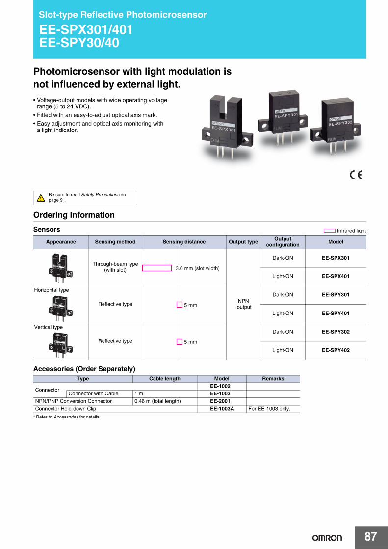
87
Slot-type Reflective Photomicrosensor
EE-SPX301/401EE-SPY30/40
Photomicrosensor with light modulation is not influenced by external light.• Voltage-output models with wide operating voltage
range (5 to 24 VDC).
• Fitted with an easy-to-adjust optical axis mark.• Easy adjustment and optical axis monitoring with
a light indicator.
Be sure to read Safety Precautions on page 91.
Ordering Information
Sensors
Accessories (Order Separately)
* Refer to Accessories for details.
Appearance Sensing method Sensing distance Output type Output configuration Model
Through-beam type(with slot)
NPN output
Dark-ON EE-SPX301
Light-ON EE-SPX401
Reflective type
Dark-ON EE-SPY301
Light-ON EE-SPY401
Reflective type
Dark-ON EE-SPY302
Light-ON EE-SPY402
Type Cable length Model Remarks
ConnectorEE-1002
Connector with Cable 1 m EE-1003NPN/PNP Conversion Connector 0.46 m (total length) EE-2001Connector Hold-down Clip EE-1003A For EE-1003 only.
Infrared light
3.6 mm (slot width)
Horizontal type
5 mm
Vertical type
5 mm
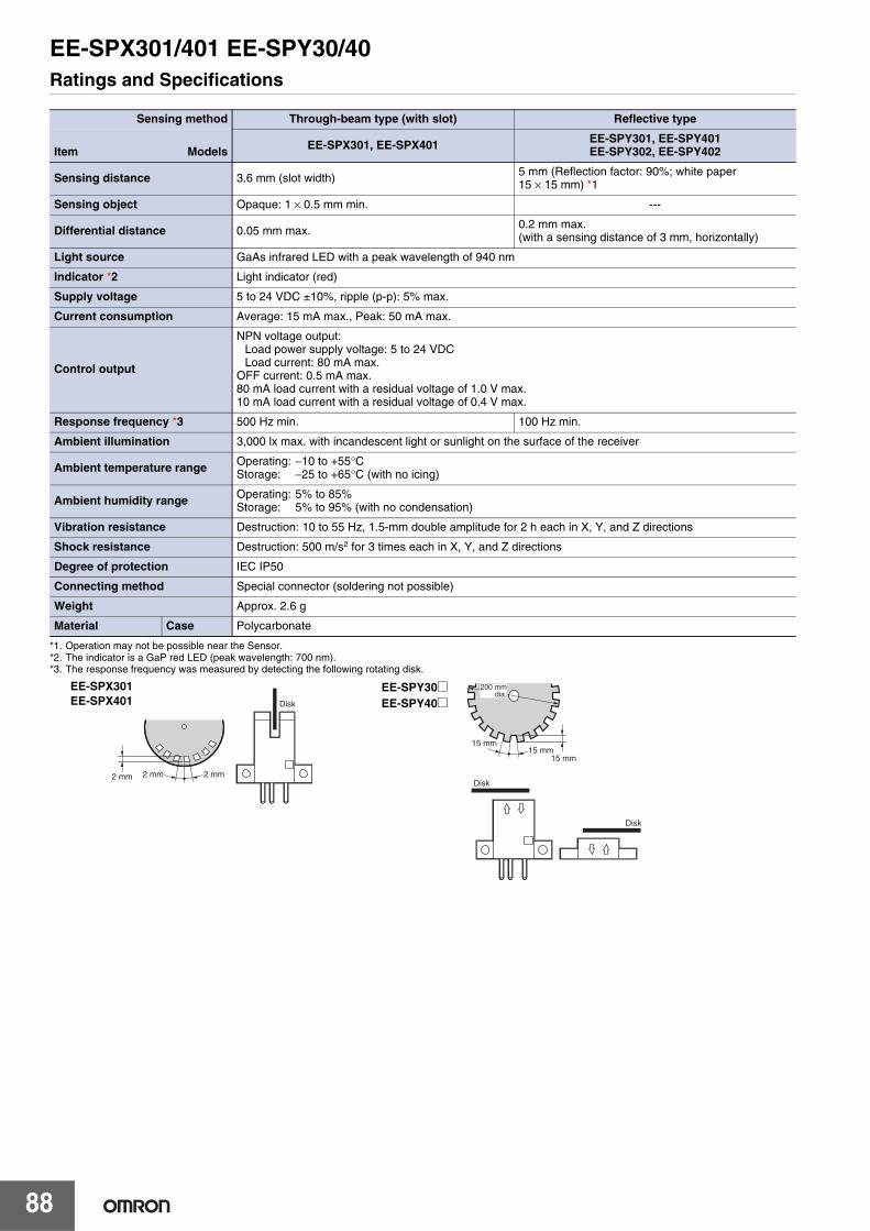
EE-SPX301/401 EE-SPY30/40
88
Ratings and Specifications
*1. Operation may not be possible near the Sensor.*2. The indicator is a GaP red LED (peak wavelength: 700 nm).*3. The response frequency was measured by detecting the following rotating disk.
Sensing method Through-beam type (with slot) Reflective type
Item Models EE-SPX301, EE-SPX401 EE-SPY301, EE-SPY401EE-SPY302, EE-SPY402
Sensing distance 3.6 mm (slot width) 5 mm (Reflection factor: 90%; white paper15 × 15 mm) *1
Sensing object Opaque: 1 × 0.5 mm min. ---
Differential distance 0.05 mm max. 0.2 mm max. (with a sensing distance of 3 mm, horizontally)
Light source GaAs infrared LED with a peak wavelength of 940 nm
Indicator *2 Light indicator (red)
Supply voltage 5 to 24 VDC ±10%, ripple (p-p): 5% max.
Current consumption Average: 15 mA max., Peak: 50 mA max.
Control output
NPN voltage output:Load power supply voltage: 5 to 24 VDCLoad current: 80 mA max.
OFF current: 0.5 mA max.80 mA load current with a residual voltage of 1.0 V max.10 mA load current with a residual voltage of 0.4 V max.
Response frequency *3 500 Hz min. 100 Hz min.
Ambient illumination 3,000 lx max. with incandescent light or sunlight on the surface of the receiver
Ambient temperature range Operating: −10 to +55°CStorage: −25 to +65°C (with no icing)
Ambient humidity range Operating: 5% to 85%Storage: 5% to 95% (with no condensation)
Vibration resistance Destruction: 10 to 55 Hz, 1.5-mm double amplitude for 2 h each in X, Y, and Z directions
Shock resistance Destruction: 500 m/s2 for 3 times each in X, Y, and Z directions
Degree of protection IEC IP50
Connecting method Special connector (soldering not possible)
Weight Approx. 2.6 g
Material Case Polycarbonate
15 mm15 mm
15 mm
Disk
Disk
200 mmdia.
Disk
2 mm2 mm2 mm
EE-SPX301EE-SPX401
EE-SPY30@EE-SPY40@
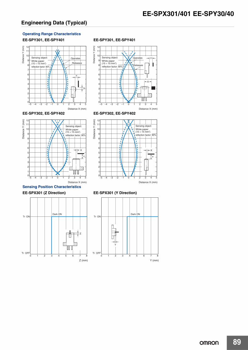
EE-SPX301/401 EE-SPY30/40
89
Engineering Data (Typical)
Operating Range Characteristics
EE-SPY301, EE-SPY401 EE-SPY301, EE-SPY401
EE-SPY302, EE-SPY402 EE-SPY302, EE-SPY402
Sensing Position Characteristics
EE-SPX301 (Z Direction) EE-SPX301 (Y Direction)
Dis
tanc
e Y
(m
m) 12
11
10
9
8
7
6
5
4
3
2
1
0−5 −4 −3 −2 −1 0 1 2 3 4 5
Distance X (mm)
Sensing object:White paper (15 × 15 mm2)reflection factor: 90%
Releases
Operates
Y
X
Dis
tanc
e Y
(m
m) 12
11
10
9
8
7
6
5
4
3
2
1
0−5 −4 −3 −2 −1 0 1 2 3 4 5
Operates
Releases
Distance X (mm)
Sensing object:White paper (15 × 15 mm2)reflection factor: 90%
X
Y
Dis
tanc
e Y
(m
m) 12
11
10
9
8
7
6
5
4
3
2
1
0−5 −4 −3 −2 −1 0 1 2 3 4 5
Distance X (mm)
Sensing object:White paper (15 × 15 mm2)reflection factor: 90%
X
Y
Dis
tanc
e Y
(m
m) 12
11
10
9
8
7
6
5
4
3
2
1
0−5 −4 −3 −2 −1 0 1 2 3 4 5
Distance X (mm)
Sensing object:White paper (15 × 15 mm2)reflection factor: 90%
Y
X
0 1 2 3 4 5 6 7 8
Z (mm)
Tr ON
Tr OFF
Dark ON
Z
0 1 2 3 4 5 6 7 8
Y (mm)
Tr ON
Tr OFF
Dark ON
Y

EE-SPX301/401 EE-SPY30/40
90
Receiver Output Excess Gain vs.
Sensing Distance Characteristics
Sensing Distance vs. Object Area
Characteristics
EE-SPY@@@ EE-SPY@@@
Sensing Angle vs. Sensing Distance
Characteristics
Dependency on Cable Length for
Operation Distance/Release Distance
EE-SPY@@@ EE-SPY@@@
Rec
eive
r ou
tput
exc
ess
gain
(m
ultip
le) 6
5
4
3
2
1
0
Distance d (mm)
1 2 3 4 5 6 7 8 9 10 11 12 13 14 15 16
Operating level
Vcc = 24 VLength of cable = 0.5 mThickness of cable = 0.3 mm2
Sensing object:White paper (15 × 15 mm2)(reflection factor: 90%)
Sen
sing
dis
tanc
e (m
m) 15
10
5
012 22 32 52 72 102 202 302 502
Sensing area l2 (mm2)
Sensing object: white paper (reflection factor: 90%)
l
l
Rel
ativ
e se
nsin
g di
stan
ce d
(%
) 110
100
90
80
70
60
50
40
30
20
10
0 −40 −30 −20 −10 0 10 20 30 40
Angle θ (°)
EE-SPY301EE-SPY302
Sensing object:White paper (15 × 15 mm2)(reflection factor: 90%)
Vcc = 24 VLength of cable = 0.5 mThickness of cable =0.3 mm2
+θ −θd
+θ −θd
Ta = 25°C Vcc = 4.5 VRL = 4.7 kΩLead: AWG24
Ope
ratin
g di
stan
ce/r
elea
se d
ista
nce
(mm
) 20
18
16
14
12
10
8
6
4
2
0
Length of cable (m)
0.1 0.3 0.5 0.7 1.0 3 5 7 10
(A)
(B)
OperatesReleases
(A): Using direct cable extension.(B): Using an externally attached capacitance of 10 μF.
Sensing object:White paper (15 × 15 mm2)(reflection factor: 90%)
C: 10 μF Attach externally

EE-SPX301/401 EE-SPY30/40
91
I/O Circuit Diagrams
NPN Output
Safety Precautions
Refer to Warranty and Limitations of Liability.
This product is not designed or rated for ensuring safety of persons either directly or indirectly.Do not use it for such purposes
Make sure that this product is used within the rated ambient environment conditions.● MountingThe sensing distance for the EE-SPY Reflective-type Photomicrosensor with built-in amplifier varies from 8 to 20 mm depending on the product (90% reflective white paper). Do not place glossy objects in the background of the sensing object.
● Wiring• Connection is made using a connector. Do not solder to the pins
(leads).• When extending the cable, use an extension cable with conductors
having a total cross-section area of 0.3 mm2. The total cable length must be 2 m maximum.
• To use a cable length longer than 2 m, attach a capacitor with a capacitance of approximately 10 μF to the wires as shown below. The distance between the terminal and the capacitor must be within 2 m. (Use a capacitor with a dielectric strength that is at least twice the Sensor's power supply voltage.)
• Make sure the total length of the power cable connected to the product is less than 10 m even if a capacitor is inserted.
Model Output configuration Timing charts Output circuit
EE-SPX401EE-SPY401EE-SPY402
Light-ON
EE-SPX301EE-SPY301EE-SPY302
Dark-ON
WARNING
Incident
Interrupted
ON
OFF
ON
OFF
Operates
Releases
H
L
Light indicator(red)
Outputtransistor
Load 1(relay)
Load 2
5 to 24 VDC
Light indicator (red)
1.5 to 3 mA Load 1
Load 2
Maincircuit
OUT
Ic ∗
* Voltage output (when the sensor is connected to a transistor circuit)
Incident
Interrupted
ON
OFF
ON
OFF
Operates
Releases
H
L
Light indicator(red)
Output transistor
Load 1(relay)
Load 2
Precautions for Correct Use
OUT
Extension cable
A capacitor of10 μF min.
+
−
5 to 24 VDC
0 V
2 m max.

EE-SPX301/401 EE-SPY30/40
92
(Unit: mm)
Dimensions Tolerance class IT16 applies to dimensions in this datasheet unless otherwise specified.
Sensors
Accessories (Order Separately)* Refer to Accessories for details.
EE-SPX301EE-SPX401
(3) (2) (1)
26
20
14
7
3.6
9
6
1824
7.5
3
1.25
3
4.2
52.5
3-0.635
Sensing window(1 × 0.5)
Two, 3.2 dia.
Indicator window(red)
Terminal Arrangement
(1) Vcc
(2) OUT OUTPUT
(3) GND (0 V)
EE-SPY301EE-SPY401
Terminal Arrangement
(1) Vcc
(2) OUT OUTPUT
(3) GND (0 V)
(3) (2) (1)
26
20
14
8
4
7
6
20 14
7.5
3
1.25
3
4.2
52.5
3-0.635
Indicator window(red)
Sensing face
Two, 3.2 dia.
EE-SPY302EE-SPY402
Terminal Arrangement
(1) Vcc
(2) OUT OUTPUT
(3) GND (0 V)
(3) (2) (1)
26
20
14
8
473.5
6
20
7.5
3
1.25
3
4.2
52.5
3-0.635
Indicator window (red)
Sensing face
Two, 3.2 dia.

93
Light Convergent Reflective Photomicrosensor
EE-SPY31/41Accurately detects objects placed in front of shiny Background.• A shiny background can be used as long as the distance between
the sensor and the background is 20 mm or more.
• Detects minute objects such as a 0.05-mm-dia. pure copper wire.• Small dispersion in sensing distance.
• Light modulation effectively reduces external light interference.
• Wide operating voltage range: 5 to 24 VDC
Be sure to read Safety Precautions on page 96.
Ordering Information
Sensors
Accessories (Order Separately)
* Refer to Accessories for details.
Appearance Sensing method Sensing distance Output type Output configuration Model
Convergentreflective type
NPN output
Dark-ON EE-SPY311
Light-ON EE-SPY411
Dark-ON EE-SPY312
Light-ON EE-SPY412
Type Cable length ModelConnector EE-1001
EE-1009
Connector with Cable1 m
EE-1006 EE-1010
2 mEE-1006 EE-1010
Connector with Robot Cable
1 m EE-1010-R 2 m EE-1010-R
NPN/PNP Conversion Connector 0.46 m (total length) EE-2002
Infrared light
Horizontal type
2 to 5 mmVerticaltype

EE-SPY31/41
94
Ratings and Specifications
I/O Circuit Diagrams
NPN Output
Item Models EE-SPY311, EE-SPY411, EE-SPY312, EE-SPY412
Sensing distance 2 to 5 mm (Reflection factor: 90%; white paper 15 × 15 mm)
Minimum sensing object Pure copper wire (0.05 mm dia.)
Distance to background *1 20 mm max. (glass with aluminum deposition) *1.
*2. The indicator is a GaP red LED (peak wavelength: 700 nm).
*3. The response frequency was measured by detecting the following rotating disk.
Differential distance 0.2 mm (with a sensing distance of 3 mm, horizontally)
Light source GaAs infrared LED with a peak wavelength of 940 nm
Indicator *2 Light indicator (red)
Supply voltage 5 to 24 VDC ±10%, ripple (p-p): 5% max.
Current consumption Average: 15 mA max., Peak: 50 mA max.
Control output
NPN voltage output:Load power supply voltage: 5 to 24 VDCLoad current: 80 mA max.
OFF current: 0.5 mA max.80 mA load current with a residual voltage of 1.0 V max.10 mA load current with a residual voltage of 0.4 V max.
Response frequency *3 100 Hz min.
Ambient illumination 3,000 lx max. with incandescent light or sunlight on the surface of the receiver
Ambient temperature range Operating: −10 to +55°CStorage: −25 to +65°C
Ambient humidity range Operating: 5% to 85%Storage: 5% to 95%
Vibration resistance Destruction: 10 to 50 Hz, 1.5-mm double amplitude for 2 h each in X, Y, and Z directions
Shock resistance Destruction: 500m/s2 for 3 times each in X, Y, and Z directions
Degree of protection IEC IP50
Connecting method Special connector (soldering not possible)
Weight Approx. 2.6 g
MaterialCase Polycarbonate
Holder Polybutylene phthalate (PBT)
Model Output configuration Timing charts Output circuit
EE-SPY411EE-SPY412 Light-ON
EE-SPY311EE-SPY312 Dark-ON
Distance to background
20 mm
Sensing object
Background object(glass with aluminum deposition)
DiskDisk
EE-SPY311/411
EE-SPY312/412
15 mm15 mm
15 mm
200 mm dia.
Incident
Interrupted
ON
OFF
ON
OFF
Operates
Releases
H
L
Light indicator(red)
Output transistor
Load 1(relay)
Load 2
Light indicator(red)
1.5 to 3 mA Load 1
Load 2∗
* Voltage output (when the sensor is connected to a transistor circuit)
OUTlc
5 to 24VDCMaincircuit
Incident
Interrupted
ON
OFF
ON
OFF
Operates
Releases
H
L
Light indicator(red)
Outputtransistor
Load 1(relay)
Load 2

EE-SPY31/41
95
Engineering Data (Typical)
Operating Range Characteristics
EE-SPY311/411 EE-SPY311/411
EE-SPY312/412 EE-SPY312/412
Sensing Distance vs. Object Area
Characteristics
Sensing Angle vs. Sensing Distance
Characteristics
Receiver Output vs. Sensing Distance
Characteristics
EE-SPY@@@ EE-SPY312/412 EE-SPY@@@
7
6
5
4
3
2
1
−5 −4 −3 −2 −1 0 1 2 3 4 50
Sensing object:White paper (15 × 15 mm2)(reflection factor: 90%)
Operates
Distance X (mm)
Dis
tanc
e Y
(m
m)
Releases
X
Y
7
6
5
4
3
2
1
0
Sensing object:White paper (15 × 15 mm2)(reflection factor: 90%)
Releases
Operates
XY
−5 −4 −3 −2 −1 0 1 2 3 4 5
Distance X (mm)
Dis
tanc
e Y
(m
m)
7
6
5
4
3
2
1
0
Sensing object:White paper (15 × 15 mm2)(reflection factor: 90%)
Releases
Operates
X
Y
−5 −4 −3 −2 −1 0 1 2 3 4 5Distance X (mm)
Dis
tanc
e Y
(m
m)
Sensing object:White paper (15 × 15 mm2)(reflection factor: 90%)
Releases
Operates
X
Y
Distance X (mm)
7
6
5
4
3
2
1
0−5 −4 −3 −2 −1 0 1 2 3 4 5
Dis
tanc
e Y
(m
m)
500
300
200
100
80
50
30
10101 2 3 5 20 50 100
Sensing object:White paper (15 × 15 mm2)(reflection factor: 90%)
Size (mm)
Rel
ativ
e se
nsin
g di
stan
ce d
(%
)
−60 −40 −20 0 20 40 60
Sensing object:White paper (15 × 15 mm2)(reflection factor: 90%)
−θ
+θ
120
100
80
60
40
20
0
Angle θ (°)
0d
Rel
ativ
e se
nsin
g di
stan
ce d
(%
)
Sensing object:White paper (15 × 15 mm2)(reflection factor: 90%)
Operating level
40
35
30
25
20
15
10
5
0
50
45
Sensing distance d (mm)
2 4 6 8 10 12
Rec
eive
r ou
tput
Vp
(mV
)

EE-SPY31/41
96
Safety Precautions
Refer to Warranty and Limitations of Liability.
This product is not designed or rated for ensuring safety of persons either directly or indirectly.Do not use it for such purposes.
Make sure that this product is used within the rated ambient environment conditions.● Wiring• Connection is made using a connector. Do not solder to the pins
(leads).
• When extending the cable, use an extension cable with conductors having a total cross-section area of 0.3 mm2. The total cable length must be 2 m maximum.
• To use a cable length longer than 2 m, attach a capacitor with a capacitance of approximately 10 μF to the wires as shown below. The distance between the terminal and the capacitor must be within 2 m. (Use a capacitor with a dielectric strength that is at least twice the Sensor's power supply voltage.)
• Make sure the total length of the power cable connected to the product is less than 10 m even if a capacitor is inserted.
(Unit: mm)
Dimensions Tolerance class IT16 applies to dimensions in this datasheet unless otherwise specified.
Sensors
WARNING
Precautions for Correct Use
2 m max.
A capacitor of 10 μF min.
5 to 24 DCV
0 V
Extension cable
OUT
Accessories (Order Separately)* Refer to Accessories for details.
Terminal Arrangement
(1) + Vcc
(2) OUT OUTPUT
(3) − GND (0 V)
EE-SPY311EE-SPY411
26
19
20
20
19 7.6
18.7
0.214
8
16.8
22.8
13.7
3.2
6.2
5 2.5 0.3 0.7
3.2
Four, R1
Four, R1.6
Sensing face (back) (10 x 5)
Indicator window(red)
Four, R2.1
(1) (2)(3)
EE-SPY312EE-SPY412
Terminal Arrangement
(1) + Vcc
(2) OUT OUTPUT
(3) − GND (0 V)
26
20
20
19 7.6
8
14
8
16.8
22.8
13.7
3.2
6.2
5 2.5 0.3 0.7
3.2
Four, R1
Four, R1.6
Sensing face (10 × 5)
Indicator window(red)
Four, R2.1
0.2
19
(1) (2)(3)

97
Reflective Photomicrosensor with Sensitivity Adjuster (Non-modulated)
EE-SY671/672Photomicrosensor with sensitivity adjuster.• Easy adjustment with a built-in sensitivity adjuster.
• Easy optical axis monitoring with a bright light indicator.• Compact design incorporating a built-in amplifier and special IC
enables direct switching capacity of up to 100 mA.
• Wide operating voltage range: 5 to 24 VDC• Connection possible with a range of ICs, relays, and Programmable
Controllers (PLCs).
Be sure to read Safety Precautions on page 100.
Ordering Information
Sensors
* The Dark-ON/Light-ON (selectable) models are normally used as dark-ON models. To use them as light-ON models, short-circuit the L terminal and positive (+) terminal. An EE-1001-1 Connector with the terminals already short-circuited is also available.
Accessories (Order Separately)
* Refer to Accessories for details.
Appearance Sensing method Sensing distance Output type Output configuration Model
Horizontaltype
Reflective type NPN output Dark-ON or Light-ON (Selectable) *
EE-SY671
Vertical type EE-SY672
Infrared light
1 to 5 mm
Type Cable length Model RemarksConnector EE-1001
EE-1001-1 L terminal and positive (+) terminal are already short-circuited.
EE-1009
Connector with Cable1 m
EE-1006 EE-1010
2 mEE-1006EE-1010
Connector with Robot Cable1 m EE-1010-R 2 m EE-1010-R
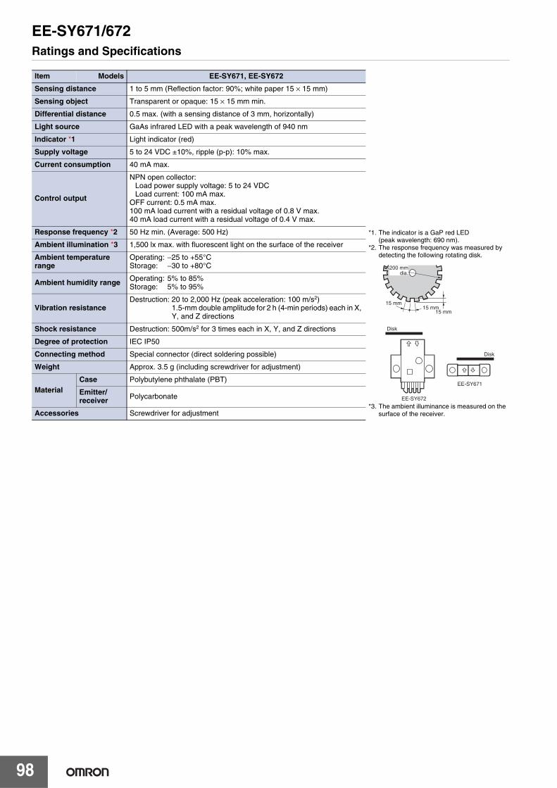
EE-SY671/672
98
Ratings and Specifications
Item Models EE-SY671, EE-SY672
Sensing distance 1 to 5 mm (Reflection factor: 90%; white paper 15 × 15 mm)
*1. The indicator is a GaP red LED (peak wavelength: 690 nm).
*2. The response frequency was measured by detecting the following rotating disk.
*3. The ambient illuminance is measured on the surface of the receiver.
Sensing object Transparent or opaque: 15 × 15 mm min.
Differential distance 0.5 max. (with a sensing distance of 3 mm, horizontally)
Light source GaAs infrared LED with a peak wavelength of 940 nm
Indicator *1 Light indicator (red)
Supply voltage 5 to 24 VDC ±10%, ripple (p-p): 10% max.
Current consumption 40 mA max.
Control output
NPN open collector: Load power supply voltage: 5 to 24 VDCLoad current: 100 mA max.
OFF current: 0.5 mA max.100 mA load current with a residual voltage of 0.8 V max.40 mA load current with a residual voltage of 0.4 V max.
Response frequency *2 50 Hz min. (Average: 500 Hz)
Ambient illumination *3 1,500 lx max. with fluorescent light on the surface of the receiver
Ambient temperature range
Operating: −25 to +55°CStorage: −30 to +80°C
Ambient humidity range Operating: 5% to 85%Storage: 5% to 95%
Vibration resistanceDestruction: 20 to 2,000 Hz (peak acceleration: 100 m/s2)
1.5-mm double amplitude for 2 h (4-min periods) each in X, Y, and Z directions
Shock resistance Destruction: 500m/s2 for 3 times each in X, Y, and Z directions
Degree of protection IEC IP50
Connecting method Special connector (direct soldering possible)
Weight Approx. 3.5 g (including screwdriver for adjustment)
MaterialCase Polybutylene phthalate (PBT)
Emitter/receiver Polycarbonate
Accessories Screwdriver for adjustment
15 mm15 mm
15 mm
Disk
EE-SY672
EE-SY671
Disk
200 mmdia.

EE-SY671/672
99
Engineering Data (Typical)
I/O Circuit Diagrams
NPN Output
Operating Range Characteristics
(Max. Sensitivity)
EE-SY67@ EE-SY67@
Sensing Distance vs. Object Area
Characteristics
Sensing Distance vs. Sensitivity
Volume
Model Output configuration Timing charts Terminal
connections Output circuit
EE-SY671EE-SY672
Light-ON
Short-circuited between
terminal and positive terminal
Dark-ON
Open between terminal and
positive terminal
Sensing object: White paper (15 × 15 mm2) (reflection factor: 90%)
22
20
18
16
14
12
10
8
6
4
2
0−6 −5 −4 −3 −2 −1 0 1 2 3 4 5 6
Dis
tanc
e Y
(m
m)
Distance X (mm)
Operates
Releases
Y
X
Y
X
Sensing object: White paper (15 × 15 mm2) (reflection factor: 90%)
22
20
18
16
14
12
10
8
6
4
2
0−6 −5 −4 −3 −2 −1 0 1 2 3 4 5 6
Dis
tanc
e Y
(m
m)
Distance X (mm)
Operates
Releases
Y
XY
X
Sensing object: White paper (15 × 15 mm2) (reflection factor: 90%)
25
20
15
10
5
012 22 32 52 72 102 202 302 502
Sensing area l2 (mm
2)
Sen
sing
dis
tanc
e (m
m)
With max. sensitivity
l
l
Paper (reflection factor: 90%)
Straw paper
Paper (reflection factor: 10%)
Black backlight
35
30
25
20
15
10
5
00 1 2 3 4 5 6 7 8 9 10
Sen
sing
dis
tanc
e (m
m)
max.min. Sensing adjuster scale
Aluminum plate
Incident
Interrupted
ON
OFF
ON
OFF
Operates
Releases
Light indicator(red)
Outputtransistor
Load 1(relay)
L
5 to 24 VDC
Load 1
Maincircuit
OUT
Light indicator (red)
Incident
Interrupted
ON
OFF
ON
OFF
Operates
Releases
Light indicator(red)
Outputtransistor
Load 1(relay)
L

EE-SY671/672
100
Safety Precautions
Refer to Warranty and Limitations of Liability.
This product is not designed or rated for ensuring safety of persons either directly or indirectly.Do not use it for such purposes.
Make sure that this product is used within the rated ambient environment conditions.● Wiring
Soldering• When direct soldering to the terminal, use the following guidelines.
Soldering Conditions
• The terminal base uses a polycarbonate resin, which could be deformed by excessive soldering heat, resulting in damage to the product’s functionality.
Cable Extension• When extending the cable, use an extension cable with conductors
having a total cross-section area of 0.3 mm2. The total cable length must be less than 10 m.
● InstallationThe photomicrosensor is built into the device being used and so is not equipped to deal with interference from an external light source. When using the sensor in an area exposed to an incandescent lamp, install so as to minimize the effects of external light sources.
● Sensitivity Adjustment
Use the special screwdriver (sold together) for sensitivity
adjustment.• When an excessive force is applied to sensitivity adjuster, it may be
damaged.• The shaft of the sensitivity adjuster is charged. Connect a DC
power supply incorporating an insulated transformer to the photomicrosensor. Do not connect a DC power supply incorporating an autotransformer or the user may receive an electric shock when adjusting the sensitivity.
WARNING
Precautions for Correct Use
Item Temperature Permissible time Remarks
Soldering iron
350°Cmax. 3 s max.
The portion between the base of the terminals and the position 1.5 mm from the terminal base must not be soldered.
Power source
Power source
+− Sensor
Autotransformer
+− Sensor
Insulated transformer

EE-SY671/672
101
Sensitivity Adjustment with Background Object
Sensitivity Adjustment with No Background Object
Point A Point B Setting Check
Sens-ingcondi-tions
Ad-justerindi-cator
AdjustmentProcedure
1. Set the sensitivity of the photomicrosensor to minimum, place the sensing object in the sensing position, turn the sensitivity adjuster clockwise slowly until the light indicator is lit (point A).
2. Remove the sensing object, at which time the light indicator will be OFF. Further turn the sensitivity adjuster clockwise slowly until the light indicator is lit again (point B). The operation indicator will not light again if the background object does not reflect light, in which case refer to ‘Sensitivity Adjustment with No Background Object”.
3. Set the sensitivity adjuster at the center (point C) between point A and B. Points A and B will be very close if the sensor is influenced by excessive light reflected by the background object, in which case take the following preventive measures.(1) Separate the sensor and
the background object by a distance of 20 mm min.
(2) Cover the surface of the background object with a material with a small reflection factor, such as black sponge.
4. After setting the sensitivity adjuster to point C, check if the light indicator is lit on placing the sensing object at the sensing position and not lit on removing the sensing object.
Point A Point B Check
Sens-ing condi-tions
Ad-juster indi-cator
AdjustmentProcedure
1. Set the sensitivity of the photomicrosensor to minimum, place the sensing object at the sensing position, turn the sensitivity adjuster clockwise slowly until the light indicator is lit (point A).
2. Set the sensitivity adjuster at the center (point C) between points A and B (the point where the sensitivity is maximum).
3. After setting the sensitivity adjuster to point C, check if the light indicator is not lit on removing the sensing object.
Background objectA
Background object
B
Background object
Black paper with smallreflection factor
CB
C
A
B
CA
C

EE-SY671/672
102
(Unit: mm)
Dimensions Tolerance class IT16 applies to dimensions in this datasheet unless otherwise specified.
Sensors
Accessories (Order Separately)* Refer to Accessories for details.
19
19 Two, 3.2 dia. holes
13.4
12.2
25.4
(31.4)
(25)
6.2
2.54
0.2
16.7
8.3
14.15
5.5
4.1
13.2
6.956.35
Sensitivityadjuster
Sensing window (back) (12.2 × 4.1)
Indicator window
0.3
0.7 0.6(3)(2) (4)(1)
Two, 3.8 dia. holes
EE-SY671
Terminal Arrangement
(1) + Vcc
(2) L L
(3) OUT OUTPUT
(4) − GND (0 V)
19
19 Two, 3.2 dia. holes
13.4
25.4
(31.2)(25)
6.2
2.54
16.7
8.35.5
13.2
6.956.35
Sensitivityadjuster
Sensing window (12.2 × 5.15)
Indicator window
0.3
0.7 0.6(3)(2) (4)(1)
Two, 3.8 dia. holes
EE-SY672
Terminal Arrangement
(1) + Vcc
(2) L L
(3) OUT OUTPUT
(4) − GND (0 V)
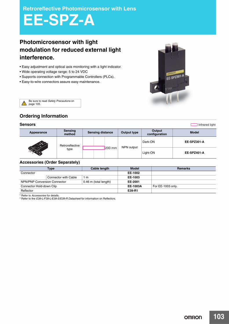
103
Retroreflective Photomicrosensor with Lens
EE-SPZ-APhotomicrosensor with light modulation for reduced external light interference.• Easy adjustment and optical axis monitoring with a light indicator.• Wide operating voltage range: 5 to 24 VDC
• Supports connection with Programmable Controllers (PLCs).
• Easy-to-wire connectors assure easy maintenance.
Be sure to read Safety Precautions on page 105.
Ordering Information
Sensors
Accessories (Order Separately)
* Refer to Accessories for details.* Refer to the E39-L/F39-L/E39-S/E39-R Datasheet for information on Reflectors.
Appearance Sensing method Sensing distance Output type Output
configuration Model
Retroreflectivetype NPN output
Dark-ON EE-SPZ301-A
Light-ON EE-SPZ401-A
Infrared light
200 mm
Type Cable length Model RemarksConnector EE-1002
Connector with Cable 1 m EE-1003NPN/PNP Conversion Connector 0.46 m (total length) EE-2001Connector Hold-down Clip EE-1003A For EE-1003 only.Reflector E39-R1

EE-SPZ-A
104
Ratings and Specifications
Engineering Data (Typical)
Receiver Output Excess Gain vs. Sensing Distance Characteristics
Item Models EE-SPZ301-A, EE-SPZ401-A
Sensing distance *1 200 mm (using E39-R1 reflector)
Light source GaAs infrared LED (pulse lighting) with a peak wavelength of 940 nm
Indicator *2 Light indicator (red)
Supply voltage 5 to 24 VDC ±10%, ripple (p-p): 5% max.
Current consumption Average: 15 mA max., Peak: 50 mA max.
Control output
NPN voltage outputLoad power supply voltage: 5 to 24 VDCLoad current: 80 mA max.
OFF current: 0.5 mA max.80 mA load current with a residual voltage of 1.0 V max.10 mA load current with a residual voltage of 0.4 V max.
Response frequency *3 100 Hz min.
Ambient illumination 3,000 lx max. with incandescent light or sunlight on the surface of the receiver
Ambient temperature range Operating: −10 to +55°CStorage: −25 to +65°C
Ambient humidity range Operating: 5% to 85%Storage: 5% to 95%
Vibration resistance Destruction: 10 to 55 Hz, 1.5-mm double amplitude for 2 h each in X, Y, and Z directions
Shock resistance Destruction: 500 m/s2 for 3 times each in X, Y, and Z directions
Degree of protection IEC IP50
Connecting method Special connector (soldering not possible)
Weight (packaged) Approx. 3 g
MaterialCase
PolycarbonateLens
*1. Operation may not be possible near the sensor.*2. The indicator is a GaP red LED
(peak wavelength: 700 nm).*3. The response frequency was measured by
detecting the following rotating disk.
40 mm60 mm
60 mm
Reflector
Disk
200 mmdia.
Operating level
Rec
eive
r ou
tput
(m
V) 20
18
16
14
12
10
8
6
4
2
0
Ta = 25°CVcc = 5 V
50 100 150 200 250 300 350 400
ReflectorE39-R1
Distance d (mm)
White paper (reflection factor: 90%)
EE-SPZ301-AEE-SPZ401-A
⎫⎬⎭
+ E39-R1 Reflector

EE-SPZ-A
105
I/O Circuits
NPN Output
Safety Precautions
Refer to Warranty and Limitations of Liability.
This product is not designed or rated for ensuring safety of persons either directly or indirectly.Do not use it for such purposes.
Make sure that this product is used within the rated ambient environment conditions.
● Wiring• Connection is made using a connector. Do not solder to the pins
(leads).• When extending the cable, use an extension cable with conductors
having a total cross-section area of 0.3 mm2. The total cable length must be 2 m maximum.
• To use a cable length longer than 2 m, attach a capacitor with a capacitance of approximately 10 μF to the wires as shown below. The distance between the terminal and the capacitor must be within 2 m. (Use a capacitor with a dielectric strength that is at least twice the Sensor's power supply voltage.)
• Make sure the total length of the power cable connected to the product is less than 10 m even if a capacitor is inserted.
Model Output configuration Timing charts Output circuit
EE-SPZ401-A Light-ON
EE-SPZ301-A Dark-ON
Incident
Interrupted
ON
OFF
ON
OFF
Operates
Releases
H
L
Light indicator(red)
Output transistor
Load 1(relay)
Load 2
Light indicator (red)
1.5 to 3 mA Load 1
Load 2
Main circuit
OUT
Ic ∗
∗ Voltage output (when the sensor is connected to a transistor circuit)
5 to 24 VDC
Incident
Interrupted
ON
OFF
ON
OFF
Operates
Releases
H
L
Light indicator(red)
Outputtransistor
Load 1(relay)
Load 2
WARNING
Precautions for Correct Use
Extension cable
A capacitor of10 μF min.
+
−
5 to 24 VDC
0 V
2 m max.
OUT

EE-SPZ-A
106
(Unit: mm)
Dimensions Tolerance class IT16 applies to dimensions in this datasheet unless otherwise specified.
Sensors
* Refer to Accessories for details.* Refer to the E39-L/F39-L/E39-S/E39-R Datasheet for information on Reflectors.
26
2620145
2.5
1.25
7.525
Two, 3.2 dia. holes
Indicator window (red)
6
3
4
3.4 dia.
3 4.47.4
(3)
(2)
(1)
2.4
4.6
3.7
EE-SPZ301-AEE-SPZ401-A
Terminal Arrangement
(1) Vcc
(2) OUT OUTPUT
(3) GND (0 V)

107
Pipe-mounting Liquid Level Photomicrosensor with Built-in Amplifier
EE-SPX613 Liquid Level Photomicrosensor with operation mode and sensitivity selectors for easy application.• Operation mode selector allows modes to be switched easily.• Sensitivity selector is suitable for any 6- to 13-mm-diameter transparent or
semi-transparent pipe with a wall thickness of 1 mm.
• Uses a clean (with no powder parting agent) cable.• Operating voltage range: 12 to 24 VDC
Be sure to read Safety Precautions on page 109.
Ordering Information
Appearance Sensing method Output type Output configuration Cable length Model
Through-beam type NPN output Dark-ON or Light-ON
(selectable) 1 m EE-SPX613 1M

EE-SPX613
108
Ratings and Specifications
I/O Circuit Diagrams
NPN Output
Item Models EE-SPX613
Applicable pipe Any 6- to 13-mm-diameter pipe with a wall thickness of 1 mm that is made of FEP or any other material as transparent as FEP.
Sensing object Liquids in pipes (High-viscosity liquids or liquids with floating materials may not be detected.)
Light source GaAs infrared LED with a peak wavelength of 940 nm
Indicator Light indicator GaP (Red LED: Peak wavelength of 700 nm)
Supply voltage 12 to 24 VDC ±10%, ripple (p-p): 5% max.
Current consumption Average: 30 mA max., Peak: 80 mA max.
Control output
NPN open collector: Load power supply voltage: 5 to 24 VDCLoad current: 100 mA max.
OFF current: 0.5 mA max.100 mA load current with a residual voltage of 0.8 V max.40 mA load current with a residual voltage of 0.4 V max.
Ambient illumination 3,000 lx max. with incandescent light or sunlight on the surface of the receiver
Ambient temperature range
Operating: −10 to +55°CStorage: −25 to +65°C (with no icing or condensation)
Ambient humidity range
Operating: 5% to 85%Storage: 5% to 95% (with no condensation)
Vibration resistance Destruction: 10 to 500 Hz, 1.0-mm single amplitude or 150 m/s2 in X, Y, and Z directions 3 times and for 11 min each
Shock resistance Destruction: 500 m/s2 for 3 times each in X, Y, and Z directions
Degree of protection IEC 60529 IP50
Connecting method Pre-wired (Standard length: 1 m)
Weight (packed state) Approx. 55 g
MaterialCase
PolycarbonateCover
Accessories Support belt (2), slip protection tube (2), Instruction Manual
Model Output configuration Timing charts Operation
mode selector Output circuit
EE-SPX613
Dark-ON D·ON(DARK ON)
Light-ON L·ON(LIGHT ON)
Incident (with no liquid)
Interrupted (with liquid)
ON
OFF
ON
OFF
Operates
Releases
Light indicator(red)
Outputtransistor
Load(relay)
Light indicator(red)
Load
Maincircuit
OUT
(Brown)
(Black)
(Blue)
12 to 24 VDCIncident (with no liquid)
Interrupted (with liquid)
ON
OFF
ON
OFF
Operates
Releases
Light indicator(red)
Outputtransistor
Load(relay)

EE-SPX613
109
Operation
The EE-SPX613 detects the level of liquid by detecting the difference in refractive index between the air and liquid.
Sensitivity selector (available only with EE-SPX613)If the diameter of the pipe is close to 6 mm, some of the emitted beam may reach the receiver because the angle of refraction is small, thus making the stable operation of the EE-SPX613 difficult.In such cases, set the sensitivity selector to Low and check that EE-SPX613 operation is stable. If there are floating materials on the surface on the liquid, some of the emitted beam may reach the receiver after it is reflected by the floating materials, thus making the stable operation of the EE-SPX613 difficult. In such cases, set the sensitivity selector to Low to stabilize operation.For normal use, set the sensitivity selector to High to account for reduced sensitivity caused by deterioration of the emitter due to age and stains on the pipe.
Safety Precautions
Refer to Warranty and Limitations of Liability.
This product is not designed or rated for ensuring safety of persons either directly or indirectly.Do not use it for such purposes.
Make sure that this product is used within the rated ambient environment conditions.● Nomenclature
EE-SPX613
● Mounting• The EE-SPX613 may not operate correctly if it is attached to an
unsuitable pipe (e.g., opaque pipe).• Always use the supporting belts and slip protection tubes that are
provided with the EE-SPX613 when attaching the EE-SPX613 to a pipe, as shown in the following illustration, and make sure that the pipe is in the center of the sensor slot and not separated from the pedestal. When tightening the supporting belts, make sure that the pipe will not be deformed.
• When attaching the EE-SPX613 to a pipe with a supporting belt, make sure that the pipe will not be deformed.
● Wiring• Do not impose any excessive force on the cable. Do not pull the
cable with any tractive force exceeding 30 N.• When extending the cable, use an extension cable with conductors
having a total cross-section area of 0.15 mm2. The total cable length must be 5 m maximum.
● Adjustment• The EE-SPX613 requires 10 ms to be in stable operation after
power is supplied.If separate power supplies are used for the EE-SPX613 and load, be sure to supply power to the EE-SPX613 before supplying power to the load.
• Make sure that smoke, air bubbles, or water droplets are not able to form either inside or outside the pipe. Otherwise, a malfunction may occur.
• Do not impose any force exceeding 5 N on the operation mode selector or sensitivity selector.
● Others
Operating Environment• Do not use the EE-SPX613 outdoors.• Do not use the EE-SPX613 in places where water, oil, or chemical
may be sprayed onto the EE-SPX613. The exterior coverings of the EE-SPX613 are made of polycarbonate. Keep the coverings away from any alkaline, aromatic hydrocarbon, or aliphatic chloride hydrocarbon solvents, all of which will damage the coverings.
• Do not use the EE-SPX613 in places where the EE-SPX613 is subject to direct sunlight, corrosive gas or salt air.
1. If there is no liquid in the pipe, the emitted beam will reach the receiver after it is refracted by the pipe. (Light incident.)
2. If there is liquid in the pipe, the emitted beam will pass through the liquid and not reach the receiver.(Light interrupted.)
Pipe
Pipe
Without liquid
With liquid
Em
itter
Receiver
Em
itter
Receiver
WARNING
Precautions for Correct Use
Operation selectorSensitivity selector
Light indicator(red)
Cable
Slip protectiontubes
Supporting belts
PedestalSensor
Pipe

EE-SPX613
110
(Unit: mm)
Dimensions Tolerance class IT16 applies to dimensions in this datasheet unless otherwise specified.
Vinyl-insulated round cable of 3.5 dia., 3 cores,(0.15 mm2 with 1.0-dia. insulator); Standard length: 1 m
6.6 dia.
Sensing window (1.8 × 0.8)Optical axis
1.6
9.212.4
1
4.9
4.5
Indicator window8.13.1
Sensitivity selector
3.5
Operation selector Cable
1.8
17.2
26
13
Pedestal
16 14.4 8.5
Optical axis
EE-SPX613
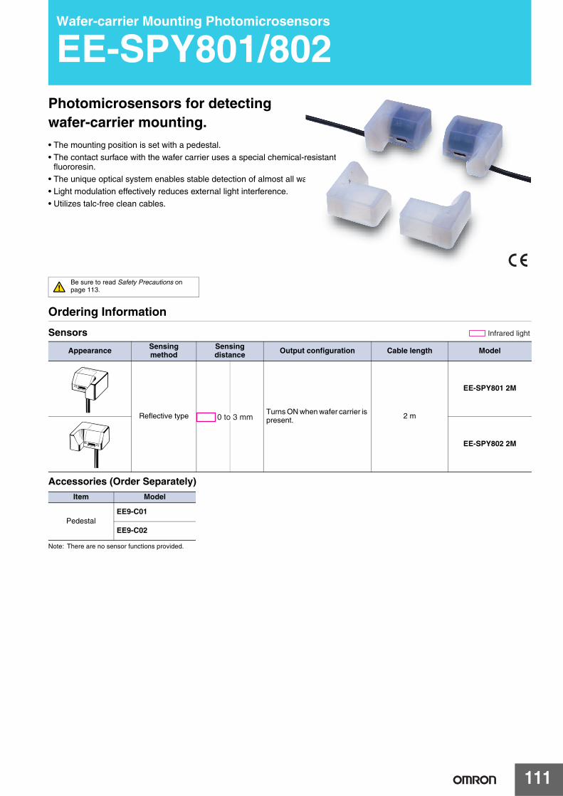
111
Wafer-carrier Mounting Photomicrosensors
EE-SPY801/802Photomicrosensors for detecting wafer-carrier mounting.• The mounting position is set with a pedestal.
• The contact surface with the wafer carrier uses a special chemical-resistant fluororesin.
• The unique optical system enables stable detection of almost all wafer-carriers.
• Light modulation effectively reduces external light interference.
• Utilizes talc-free clean cables.
Be sure to read Safety Precautions on page 113.
Ordering Information
Sensors
Accessories (Order Separately)
Note: There are no sensor functions provided.
Appearance Sensing method
Sensing distance Output configuration Cable length Model
Reflective type Turns ON when wafer carrier is present. 2 m
EE-SPY801 2M
EE-SPY802 2M
Infrared light
0 to 3 mm
Item Model
PedestalEE9-C01
EE9-C02

EE-SPY801/802
112
Ratings and Specifications
I/O Circuit Diagrams
Item Models EE- SPY801/802
Sensing distance(Standard sensing object)
0 to 5 mm (White paper: 15 × 15 mm2, reflection factor: 90%)0 to 3 mm (Black paper: 15 × 15 mm2, reflection factor: 10%)
Sensing object Transparent or opaque wafer carriers
Operation indicator Lit orange when object is detected.
Light source GaAs infrared LED with a peak wavelength of 940 nm
Supply voltage 12 to 24 VDC ±10%, ripple (p-p): 5% max.
Current consumption 30 mA max.
Control output
NPN open collector: Load power supply voltage: 5 to 24 VDCLoad current: 100 mA max.
OFF current: 0.5 mA max.100 mA load current with a residual voltage of 0.8 V max.40 mA load current with a residual voltage of 0.4 V max.
Response time 5 ms max.
Ambient illumination 3,000 lx max. with incandescent light or sunlight on the surface of the receiver
Ambient temperature range Operating: −10 to +55°CStorage: −25 to +65°C (with no icing)
Ambient humidity range Operating: 5% to 85%Storage: 5% to 95% (with no condensation)
Vibration resistance Destruction: 1 to 500 Hz, 1.0-mm single amplitude or 150 m/s2 each in X, Y, and Z directions3 times and for 11 min. each
Shock resistance Destruction: 500 m/s2 for 3 times each in X, Y, and Z directions
Degree of protection IEC IP30
Connecting method Pre-wired (Standard length: 2 m)
Weight (packaged) Sensor: Approx. 43 g; Accessory (Pedestal): Approx. 9 g
MaterialCase Ethylene tetrafluoro ethylene (ETFE)
Base plate Polybutylene phthalate (PBT)
Accessories Instruction Manual
Model Output configuration Timing charts Output circuit
EE-SPY801EE-SPY802
Turns ON when wafer carrier is present.
With wafer carrier
Without wafer carrier
ON
OFF
ON
OFF
Operates
Releases
Operation indicator(orange)
Output transistor
Load(etc., relay)
OUT(Black)
Operation indicator (orange)
− (Blue)
+ (Brown)
Main circuit
Load
12 to 24 VDC

EE-SPY801/802
113
Standard Usage
This sensor is designed to detect wafer-carrier mountings. The bottom of the wafer carrier has a ribbed construction for the leg section, as shown in the following diagram. The EE-SPY801/802 detects the wafer-carrier mounting using a reflective optical sensor that detects the leg section of the wafer-carrier.
Install a Sensor (or Pedestal) at each of the four corners indicated by a circle in the following diagram.
Safety Precautions
Refer to Warranty and Limitations of Liability.
This product is not designed or rated for ensuring safety of persons either directly or indirectly.Do not use it for such purposes.
Make sure that this product is used within the rated ambient environment conditions.● WiringWhen extending the cable, use an extension cable with conductors having a total cross-section area of 0.15 mm2 (AWG26 equivalent). The total cable length must be 5 m maximum.To use a cable length longer than 5 m, attach a capacitor with a capacitance of approximately 10 μF to the wires as shown below. The distance between the terminal and the capacitor must be within 5 m.
● MountingMount the Photomicrosensors securely on a flat surface, and tighten the mounting screws using a tightening force of 0.30 N·m max. (Using a spring washer is recommended to prevent the screws from becoming loose.)
● AdjustmentThe EE-SPY801/802 requires 10 ms to be in stable operation after power is supplied.If separate power supplies are used for the EE-SPY801/802 and load, be sure to supply power to the EE-SPY801/802 before supplying power to the load.
● Operating EnvironmentDo not use the EE-SPY801/802 in locations subject to salty air or corrosive gases, such as hydrogen chloride gas.
Sensor
Wafer carrier leg section
Wafer carrier side view (details omitted)
(Side view)
Sensor
A and C EE-SPY801 or EE9-C01
B and D EE-SPY802 or EE9-C02
Wafer carrier side view (details omitted)
(Top view)
A D
B C
WARNING
Precautions for Correct Use

EE-SPY801/802
114
(Unit: mm)
Dimensions Tolerance class IT16 applies to dimensions in this datasheet unless otherwise specified.
Sensors
Accessories (Order Separately)
3222
11
30+1.3 0
8
2
Sensingwindow
Indicator window (orange)
5
2
Two, M4 (depth: 6)
15
87.4
6
Vinyl-insulated round cable of3.5 dia., 3 cores, (0.15 mm2 with 1.0-dia. insulator); Standard length: 2 m
3.515
35°35°
+1.3 −0.3
EE-SPY801
32+1.3 −0.3
22
11
30+1.3 0
2
Sensing window
Indicator window (orange)
5
2
Two, M4 (depth: 6)
15
87.4
6
Vinyl-insulated round cableof 3.5 dia., 3 cores, (0.15 mm2 with 1.0-dia. insulator); Standard length: 2 m
3.515
35° 35°8
EE-SPY802
32+1.3 −0.3
22
11
30+1.3 0
5
2
Two, M4 (depth: 6)
15
615
35°35°
Pedestal
EE9-C0132+1.3
−0.3
22
11
30+1.3 0
5
2
Two, M4 (depth: 6)
15
615
35° 35°
Pedestal
EE9-C02

115
Pushbutton-type Photomicrosensor
EE-SA701/801Using a pushbutton enables accurately detecting difficult-to-detect objects.• Conforms to standards for semiconductor FOUP cassettes to enable
accurately detecting FOUP cassettes without being affected by the material, color, or reflectance of the bottoms of the cassettes.
• Thin design enables mounting in a wider range of applications, e.g., on transfer arms.
• Increased visibility with 4-direction indicator.
• Optical detection of actuator operation provides a long life (mechanical life: 5 million operations min.).
• Models available with PNP or NPN output.
• Models are available with very flexible robot cable.
Be sure to read Safety Precautions on page 119.
Ordering Information
List of Models
Note: 1. Distance from the top surface of the housing to the top of the actuator. 2. Output reverses between 3.5 and 4.5 mm.
Appearance Sensing distance Sensing method Operation mode Cable length
ModelNPN output PNP output
Pushbutton
ON with no load
1 m EE-SA801A 1M EE-SA801R 1M
1 m(robot cable)
EE-SA801A-R 1M EE-SA801R-R 1M
OFF with no load EE-SA701-R 1M EE-SA701P-R 1M
(See note 2.)0 to 3.5 mm (pressed position) (See note 1.)

EE-SA701/801
116
Ratings and Specifications
Note: 1. Free position (FP): The position of the top of the actuator when no force is being applied to the actuator.Operating position (OP): The position of the top of the actuator when the actuator is pressed and the output transistor changes from OFF to ON for the EE-
SA701-R/-SA701P-R and from ON to OFF for all other models.Total travel position (TTP): The position of the top of the actuator when the actuator is pressed as far as it can be pressed.
2. This does not indicate that the output will be ON from 3.5 to 4.5 mm, but rather that the output will change from ON to OFF at some point between 3.5 and 4.5 mm.
3. The force required to press the actuator from the FP to the OP.
ItemModel
NPN output EE-SA801A EE-SA801A-R EE-SA701-RPNP output EE-SA801R EE-SA801R-R EE-SA701P-R
Indicator Lights red when actuator is pressed. Lit red while there is no load on actuator
Operation Specifica-tions (See
Free position (FP) 5.0±0.4 mmOperating position (OP) 3.5 to 4.5 mm (See note 2.)Total travel position (TTP) 0 mm max.
Operating load (See note 3.) 3 N max. (typical: 0.5 N) Supply voltage 12 to 24 VDC±10%, ripple (p-p): 10% max.Current consumption 35 mA max.
Control output
NPN Models: NPN open collector, 5 to 24 VDC, 50 mA max.;residual voltage of 0.4 V max. at 50-mA load currentOFF current: 0.5 mA max.
PNP Models: PNP open collector, 5 to 24 VDC, 50 mA max.;residual voltage of 0.4 V max. at 50-mA load currentOFF current: 0.5 mA max.
External diagnosis inputInput
NPN ModelsEmission OFF: Shorted to 0 V or 0.5 V max. (source current: 30 mA max.) Emission ON: Open (leakage current: 0.4 mA max.)PNP ModelsEmission OFF: Shorted to +DC or +DC-0.5 V max. (sink current: 30 mA max.) Emission ON: Open (leakage current: 0.4 mA max.)
Response time 1 ms max.Protection circuits Reversed power supply polarity protection
Ambient temperature range Operating: −25 to +55°CStorage: −30 to +60°C (with no icing or condensation)
Ambient humidity range Operating: 5% to 85%Storage: 5% to 95% (with no condensation)
Mechanical durability 5,000,000 operations min. (One operation is from the free position to operating position and back to the free position.)
Vibration resistance Destruction: 10 to 500 Hz, 1.0-mm single amplitude or 150 m/s2 3 times each in X, Y, and Z di-rections for 11 min. each
Shock resistance Destruction: 500 m/s2 for 3 times each in X, Y, and Z directionsDegree of protection IEC IP40
Connecting method Pre-wired (standard cable length: 1 m) Pre-wired (robot cable length: 1 m)
Weight Approx. 16.1 g
MaterialCase PolycarbonateActuator Polyacetal
Accessories Instruction Manual
TT
P
OP
FP

EE-SA701/801
117
I/O Circuit Diagrams
Model Operating Mode Timing chart Output circuit
EE-SA801AEE-SA801A-R ON with no load
EE-SA701-R OFF with no load
EE-SA801REE-SA801R-R ON with no load
EE-SA701P-R OFF with no load
Present
Absent
ON
OFF
ON
OFF
Operates
Releases
Push indicator (red)
Sensing object
Output transistor
Load (e.g., relay)
Brown
White
Blue
Black
12 to 24 VDC
Push indicator (red)
Main circuit
Load (relay)
ZD
ZD
50 mA max.
(External diagnosis input)
(Control output)
Present
Absent
ON
OFF
ON
OFF
Operates
Releases
Push indicator (red)
Sensing object
Output transistor
Load (e.g., relay)
Present
Absent
ON
OFF
ON
OFF
Operates
Releases
Push indicator (red)
Sensing object
Output transistor
Load (e.g., relay)
ZD
ZD
Brown
White
Blue
Black
12 to 24 VDC
Push indicator (red)
Main circuit
Load (relay)
50 mA max.
(External diagnosis input)
(Control output)
Present
Absent
ON
OFF
ON
OFF
Operates
Releases
Push indicator (red)
Sensing object
Output transistor
Load (e.g., relay)
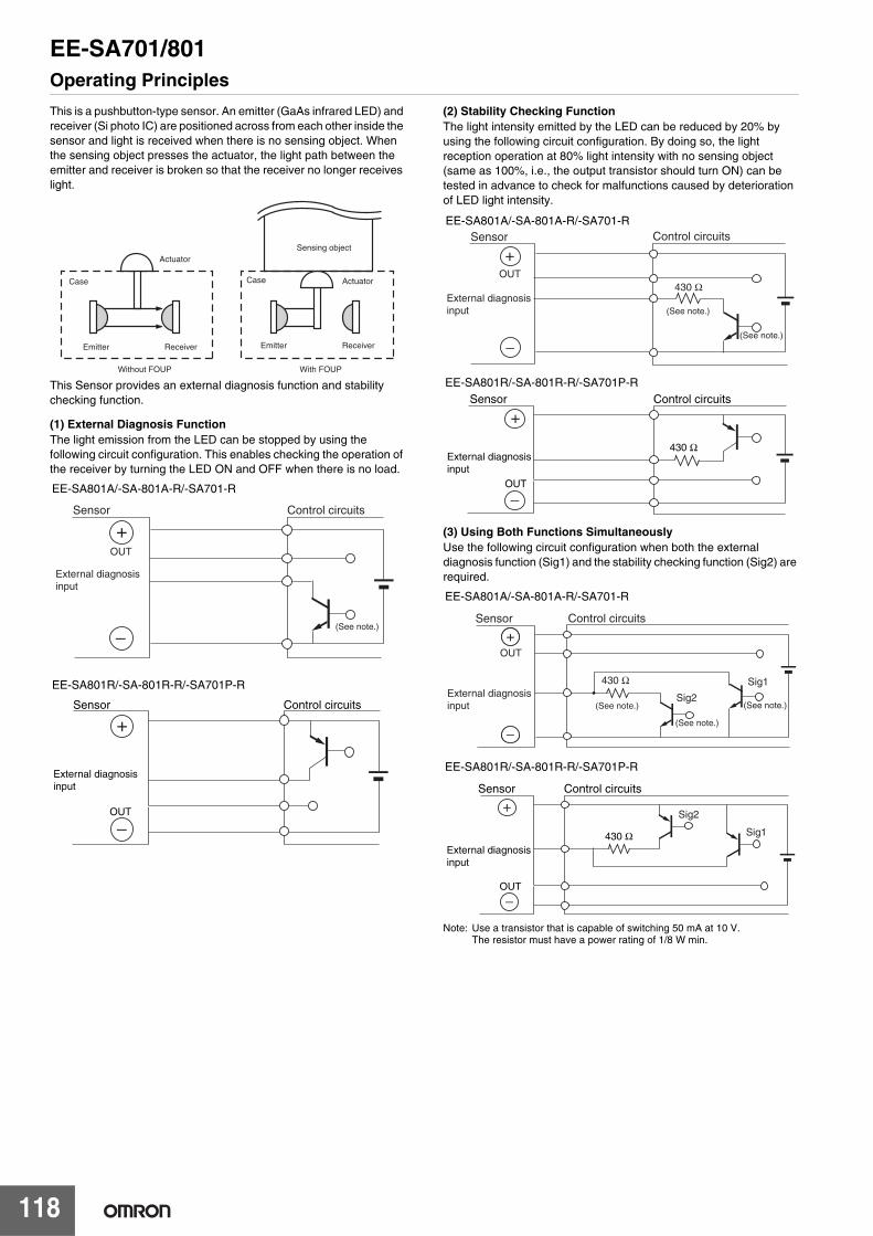
EE-SA701/801
118
Operating Principles
This is a pushbutton-type sensor. An emitter (GaAs infrared LED) and receiver (Si photo IC) are positioned across from each other inside the sensor and light is received when there is no sensing object. When the sensing object presses the actuator, the light path between the emitter and receiver is broken so that the receiver no longer receives light.
This Sensor provides an external diagnosis function and stability checking function.
(1) External Diagnosis FunctionThe light emission from the LED can be stopped by using the following circuit configuration. This enables checking the operation of the receiver by turning the LED ON and OFF when there is no load.
(2) Stability Checking FunctionThe light intensity emitted by the LED can be reduced by 20% by using the following circuit configuration. By doing so, the light reception operation at 80% light intensity with no sensing object (same as 100%, i.e., the output transistor should turn ON) can be tested in advance to check for malfunctions caused by deterioration of LED light intensity.
(3) Using Both Functions Simultaneously Use the following circuit configuration when both the external diagnosis function (Sig1) and the stability checking function (Sig2) are required.
Note: Use a transistor that is capable of switching 50 mA at 10 V. The resistor must have a power rating of 1/8 W min.
Emitter
Case
Without FOUP With FOUP
Actuator
Receiver
Sensing object
Emitter
Case Actuator
Receiver
External diagnosisinput
Control circuitsSensor
OUT
(See note.)
EE-SA801A/-SA-801A-R/-SA701-R
External diagnosis input
Sensor Control circuits
OUT
EE-SA801R/-SA-801R-R/-SA701P-R
OUT430 Ω
Control circuitsSensor
External diagnosis input
(See note.)
(See note.)
EE-SA801A/-SA-801A-R/-SA701-R
Sensor Control circuits
OUT
430 ΩExternal diagnosis input
EE-SA801R/-SA-801R-R/-SA701P-R
OUT
430 Ω
Sig2
Sig1
Control circuitsSensor
External diagnosis input
(See note.)
(See note.)(See note.)
EE-SA801A/-SA-801A-R/-SA701-R
Sensor Control circuits
OUT
External diagnosis input
430 Ω Sig1
Sig2
EE-SA801R/-SA-801R-R/-SA701P-R

EE-SA701/801
119
Safety Precautions
Refer to Warranty and Limitations of Liability.
This product is not designed or rated for ensuring safety of persons either directly or indirectly. Do not use it for such purposes.
Make sure that the Photomicrosensor is used within the rated ambient environment conditions.
● MountingMount the Photomicrosensor securely on a flat surface using M3 pan head screws, and tighten the mounting screws using a tightening force of 0.59 N·m max.
AdjustmentThe EE-SA801 requires 10 ms to be in stable operation after power is supplied. If separate power supplies are used for the EE-SA801 and load, be sure to supply power to the EE-SA801 before supplying power to the load.
Operating Environment• The EE-SA801 is not watertight. Do not use the EE-SA801
outdoors.• Do not use the EE-SA801 in places where water, oil, or chemical
may be sprayed onto the EE-SA801. The exterior coverings of the EE-SA801 are made of polycarbonate. Keep the coverings away from any alkaline, aromatic hydrocarbon, or aliphatic chloride hydrocarbon solvents, all of which will damage the coverings.
(Unit: mm)
Dimensions Tolerance class IT16 applies to dimensions in this datasheet unless otherwise specified.
Sensor
WARNING
Precautions for Correct Use
13±0
.2
Indicator window
20±0.3
6.5±0.121.3±0.2
25±0.3
9±0.2
18±0.2
14
2.24
2.24
3
3
Four, R3
Six, R3
1,000±50
4 4
5±0.4 SR4
Indicator window
Indicator window
Two, 3.3-dia. holes with 6.3 countersinking, depth: 1.65
(14)
(2.8 dia.)
EE-SA801A/EE-SA801RVinyl-insulated round cable of 2.8 dia., 4 cores,(0.14 mm2 conductor cross-sectional area with 0.85-mm dia. insulator); Standard length: 1 m
EE-SA801A-R/EE-SA801R-R EE-SA701-R/EE-SA701P-R Cable for robot instrumentation of 2.8 dia., 4 cores,(0.15 mm2 conductor cross-sectional area with 0.8-mm dia. insulator); Standard length: 1 m
EE-SA801A/-SA801A-REE-SA801R/-SA801R-REE-SA701-REE-SA701P-R

120
Accessories (Order Separately)
Ordering InformationConnectors and Connector Hold-down Clips
*1. EE-1009- or EE-1010-series Connectors have a builtin locking mechanism to prevent cable disconnection when only the cable is pulled. To remove the Connector from the Sensor, grip the top and bottom of the Connector firmly and push into the Sensor once before pulling out. The locking mechanism prevents the Connector from being removed by pulling on the cable only and enables removal only when the Connector (housing) is pulled.
*2. The case (housing) and dispersion pins (for hand-crimping) for EE-1006 Connectors can be ordered separately. Use the EE-1006T Special Crimping Tool to prepare the Connector.
Applicable Sensor modelsEE-SX67@ (A, P, R), EE-SX47@, EE-SY67@, EE-SPY31@/41@, EE-SPX303N/403N, EE-SPW311/411
Type Cable length Model Remarks
ConnectorEE-1001EE-1001-1 L terminal and positive (+) terminal are already short-circuited.EE-1009 *1
Connector with Cable
1 mEE-1006 4 conductorsEE-1010 *1
2 m
EE-1006 4 conductorsEE-1006D 3 conductorsEE-1006L 2 conductorsEE-1010 *1
Connector with Robot Cable
1 m EE-1010-R *12 m EE-1010-R *1
NPN/PNP Conversion Connector
0.46 m (total length) EE-2002
Connector Hold-down Clip EE-1006A For EE-1006, EE-SX670@, 470, EE-SY671, and 672 only.
Connector Parts *2
Case (housing) EE-1006H 100 per cartonDispersion Pins EE-1006C 500 per carton
Special Crimping Tool EE-1006T
Applicable Sensor modelsEE-SX97@-C1, EE-SX97@P-C1
Item Cable length Model Remarks
Connector with Cable1 m EE-1017 1M3 m EE-1017 3M
Connector with Robot Cable1 m EE-1017-R 1M3 m EE-1017-R 3M
Applicable Sensor modelsEE-SX91@@-C1J-R (Pre-wired Connector)
Item Cable length Model RemarksConnector with Cable 2 m EE-1016-R The robot cable is standard for all models.
Applicable Sensor modelsEE-SX67@@-C1J-R (Pre-wired Connector)
Item Cable length Model RemarksConnector with Cable 2 m EE-1016-R-1 The robot cable is standard for all models.
Applicable Sensor modelsEE-SPX74@/84@
Item Cable length Model RemarksConnector with Cable 1 m EE-1013
Applicable Sensor modelsEE-SPX301/401, EE-SPY30@/40@, EE-SPZ301@/401@
Item Cable length Model RemarksConnector EE-1002
Connector with Cable 1 m EE-1003NPN/PNP Conversion Connector
0.46 m (total length)
EE-2001
Connector Hold-down Clip EE-1003A For EE-1003 only.
HandleRatchet
Crimping sectionSwitching knob
Appearance
Sensor
Connector

121
Ratings and Specifications
*1. The Connector has a built-in locking mechanism. To remove the Connector from the Sensor, grip the top and bottom of the Connector housing, as shown in the following diagram, and then pull out the Connector.
*2. EE-SX67@ and EE-SY67@ are the best used in the light-ON state.
Product Connector *1Connector with
Cable *1Connector with Robot Cable *1
Connector
Connector (short-circuit-ed between
positive (+) and L terminals) *2
Connector withCable
Model EE-1009 EE-1010 EE-1010-R EE-1001 EE-1001-1 EE-1006
Item
Appearance
Contact resistance 20 mΩ max. (at 20 mV max., 100 mA max.) 15 mΩ max. (at 100 VDC max.)10 mΩ max. (100 VDC max.)
Insertion/removal durability
50 times min. ---
Insertion strength No. of poles ✕ 6 N max. 50 N max.
Surplus strength (housing holding strength)
No. of poles ✕ 0.4 N max. --- 20 N max.
Standard cable length --- 2 m --- 2 m
Lock strength No. of poles ✕ 29 N min. ---
Ambient humidity −10 to +60°C −10 to +75°C −10 to 60°C
MaterialHousing Polybutylene phthalate (PBT)
Contact Phosphor bronze (solder plating)
Applicable Photomicrosensors
EE-SX67@ (A,P,R) (Connector Models only), EE-SX47@, EE-SY67@, EE-SPY31@/41@, EE-SPX303N/403N, EE-SPW311/411
Product Connector Connector with Cable
Connector with Cable
Connector with Cable
Connector with Robot
CableConnector with Robot Cable
Model EE-1002 EE-1003 EE-1013 EE-1017 EE-1017-R EE-1016-R EE-1016-R-1
Item
Appearance
Contact resistance10 mΩ max.(at 10 mADC and 1 ADC)
20 mΩ max. (at minute current of 1 kHz and 500 VDC) 25 mΩ max. (at 10 mA DC and 20 mV max.)
Insertion strength 20 N max. 23.5 N max. 40 N max. 20 N max.
Surplus strength (housing holding strength)
15 N min. (initial)10 N min. (ten times)
3.5 N min. 10 N min. 1.5 N min. 15 N min.
Cable length --- 1 m 1 m, 3 m 2 m
Ambient humidity −10 to +75°C −10 to +60°C −10 to +55°C −10 to +60°C −25 to +85°C
MaterialHousing Nylon
Contact Phosphor bronze (solder plating)
Applicable Photomicrosensors
EE-SPX301/401, EE-SPY30@/40@, EE-SPZ301@/401@
EE-SPX74@/84@ EE-SX97@C1, EE-SX97@P-C1
EE-SX91@-C1J-R (Pre-wired Connector)
EE-SX67@-C1J-R (Pre-wired Connector)
Sensor
Connector

122
(Unit: mm)Dimensions Tolerance class IT16 applies to dimensions in this datasheet unless otherwise specified.
Photomicrosensor Connectors and Connector Hold-down Clips
Applicable Photomicrosensors
EE-SX67@ (A,P,R) (Connector Models only), EE-SX47@, EE-SY67@,EE-SPY31@/41@, EE-SPX303N/403N, EE-SPW311/411 For EE-SX670@, 470@, EE-SY671, and 672 only.
Connector
EE-100113
4
2.54±0.15
2.9±1
0.6
10.8
6
Connector (short-circuited between positive (+) and L terminals)
EE-1001-1
3.9±0.4
2.8±0.1
0.6
10.8
6
5
1.5
0.8
13
4
1.4
2.5
3±0.3
7.62
2.545.5±0.4
11.8
5.3
2.54
0.6
16.2
20
2,000
25
15
(4)(3)(2)(1)
Cable:4-dia. 4-conductor vinyl-insulated round cable(Conductor cross section: 0.2 mm2, Insulator diameter: 1.1 mm).
Connector with Cable
EE-1006
TerminalArrangement
(1) Brown(2) L Pink(3) OUT Black(4) Blue
1.2
(R1)
2
5.5
R3
4-R1.6
10.2
19.421.9
15
25.219
12
3.2
2.133
3.6
3.4
Connector Hold-down Clip
EE-1006A(Can be used only with EE-1006 Connectors for the Photomicrosensors listed below.)
Material: Stainless steel

123
Photomicrosensor Connectors
Applicable Photomicrosensors
EE-SX67@ (A,P,R) (Connector Models only), EE-SX47@, EE-SY67@, EE-SPY31@/41@EE-SPX303N/403N, EE-SPW311/411
Connectors
EE-100913
4
2-C1
9
4.5
0.8
1.51.2
5 1.4 2.50.6
2.5 2.54
7.62
Connector with Cable
EE-1010Connector with Robot Cable
EE-1010-R
0.6
(1)(2)(3)(4)
4
2.547.6213
2-C1
5
13.5 20±5
EE-1010 cableEE-1010-R cable:4-dia. 4-conductor vinyl-insulated round cable(Conductor cross section: 0.2 mm2, Insulatordiameter: 1.1 mm).
2,000 25±5 15±5
1.4
2.5 Terminal Arrangement
(1) Brown(2) L Pink(3) OUT Black(4) Blue

124
Photomicrosensor Connectors and Connector Hold-down Clips
ApplicablePhotomicrosensors EE-SPX301/401, EE-SPY30@/40@, EE-SPZ301@/401@
Applicable Photomicrosensors EE-SPX74@/84@
Applicable Photomicrosensors EE-SX97@-C1, EE-SX97@P-C1
63
22
6
1.20.61.2
5.5
OU
T
2.55
11.5
13.5
16.62
6
16.5
0.25
4
Connector
EE-1002
Connector with Cable
EE-1003
1.7552.5110.75
4.9
10.7
1,000±20
3±1
1
(1)Brown
(2)Black
(3)Blue
Cable:1.61-dia. 1-conductor vinyl-insulated round cable(Conductor cross section: 0.33 mm2).
Connector Hold-down Clips
(For EE-1003 only)
EE-1003A
14.2
Two,3.2 dia.hole
20
25.5
5.7
8
2.9
1
11 1
3.5
4.2
1
2
2
2.51.251.8
5
5.7
2.5
7.75 20
XHP-3 (JST Mfg.)
1,000 16±2 7±1
9.8
2.9-dia. 3-conductor vinyl-insulated round cable(Conductor cross section: 0.15 mm2, Insulator diameter: 0.9 mm), Standard length: 1 m.
(3)
(2)
(1)
Connector with Cable
EE-1013
Terminal Arrangement
(1) Blue GND(0V)(2) Black OUTPUT(3) Brown Vcc
Connector with Cable
EE-1017Connector with Robot Cable
EE-1017-R
Connector with Cable: EE-1017Vinyl insulated round cord: 4 dia., 4 cores,(Cross section area of conductor: 0.2 mm2/ insulator: 1.1 mm dia.)Connector with Robot Cable: EE-1017-R
Robot instrumentation cord: 4 dia., 4 cores,(Cross section area of conductor: 0.2 mm2/ insulator: 1.1 mm dia.)
2 10
5.8 8 20±5 1,000+50
0 25±5 15±5 (8)
(1)(2)(3)(4)
Terminal Arrangement
(1) Brown(2) 1 Black(3) 2 White(4) Blue

125
NPN to PNP Transistor Output Conversion Connectors
Applicable Photo-microsensors EE-SX91@-C1J-R (Models with Junction Connectors)
Applicable Photo-microsensors
EE-SX67@-C1J-REE-SX67@P-C1J-R
Applicable Photomicrosensors
EE-SPX301/401, EE-SPY30@/40@,EE-SPZ301@/401@
EE-SX67@ (A,P,R) (Connector Models only), EE-SX47@,EE-SY67@, EE-SPY31@/41@,EE-SPX303N/403N, EE-SPW311/411
Connector with Robot Cable
EE-1016-R
210
5.8 8 10
2.8-dia. 4-conductors robot cable (Conductor cross section: 0.15 mm2,Insulation diameter: 0.8 mm), Standard length: 2 m.
7162,000
1
2
3
4
Terminal Arrangement
(1) Brown(2) OUT2 White(3) Blue(4) OUT1 Black
Connector with Cable (Connection with Robot Cable)
EE-1016-R-1
2
10
5.8 8 10
2.8-dia. 4-conductors robot cable(conductor cross-section: 0.15 mm2, insulatordiameter: 0.8 mm), Standard length: 2 m.
162,000
1
2
3
4
Terminal Arrangement
(1) Brown(2) L Pink(3) Blue(4) OUT Black
12.5
4.9
10.720 200 40 200
Connector side(sensor side)
8 dia. 12
Cable:4-dia, 3-conductors vinyl-insulated round cable(Conductor cross section: 0.2 mm2, Insulation diameter: 1.2 mm).
Cable end (end with power output)
NPN/PNP Conversion Connector
EE-2001
Terminal Arrangement
(1) Brown(2) OUT Black(3) Blue
11.8
5.3
8 dia.12
8
16.2 20 200 20040
Connector side(sensor side)
Cable:4-dia, 3-conductors vinyl-insulated round cable(Conductor cross section: 0.2 mm2, Insulation diameter: 1.2 mm).
Cable end (end with power output)
NPN/PNP Conversion Connector
EE-2002 *
Terminal Arrangement
(1) Brown(2) OUT Black(3) Blue
*The EE-SX67@ and EE-SY67@ do not support Light-ON mode.

MEMO
126

READ AND UNDERSTAND THIS DOCUMENTPlease read and understand this document before using the products. Please consult your OMRON representative if you have any questions orcomments.
WARRANTYOMRON’s exclusive warranty is that the products are free from defects in materials and workmanship for a period of one year (or other period ifspecified) from date of sale by OMRON.
OMRON MAKES NO WARRANTY OR REPRESENTATION, EXPRESS OR IMPLIED, REGARDING NON-INFRINGEMENT,MERCHANTABILITY, OR FITNESS FOR PARTICULAR PURPOSE OF THE PRODUCTS. ANY BUYER OR USER ACKNOWLEDGES THATTHE BUYER OR USER ALONE HAS DETERMINED THAT THE PRODUCTS WILL SUITABLY MEET THE REQUIREMENTS OF THEIRINTENDED USE. OMRON DISCLAIMS ALL OTHER WARRANTIES, EXPRESS OR IMPLIED.
LIMITATIONS OF LIABILITYOMRON SHALL NOT BE RESPONSIBLE FOR SPECIAL, INDIRECT, OR CONSEQUENTIAL DAMAGES, LOSS OF PROFITS ORCOMMERCIAL LOSS IN ANY WAY CONNECTED WITH THE PRODUCTS, WHETHER SUCH CLAIM IS BASED ON CONTRACT, WARRANTY,NEGLIGENCE, OR STRICT LIABILITY.
In no event shall responsibility of OMRON for any act exceed the individual price of the product on which liability is asserted.
IN NO EVENT SHALL OMRON BE RESPONSIBLE FOR WARRANTY, REPAIR, OR OTHER CLAIMS REGARDING THE PRODUCTS UNLESSOMRON’S ANALYSIS CONFIRMS THAT THE PRODUCTS WERE PROPERLY HANDLED, STORED, INSTALLED, AND MAINTAINED ANDNOT SUBJECT TO CONTAMINATION, ABUSE, MISUSE, OR INAPPROPRIATE MODIFICATION OR REPAIR.
SUITABILITY FOR USETHE PRODUCTS CONTAINED IN THIS DOCUMENT ARE NOT SAFETY RATED. THEY ARE NOT DESIGNED OR RATED FOR ENSURINGSAFETY OF PERSONS, AND SHOULD NOT BE RELIED UPON AS A SAFETY COMPONENT OR PROTECTIVE DEVICE FOR SUCHPURPOSES. Please refer to separate catalogs for OMRON's safety rated products.
OMRON shall not be responsible for conformity with any standards, codes, or regulations that apply to the combination of products in thecustomer’s application or use of the product.
At the customer’s request, OMRON will provide applicable third party certification documents identifying ratings and limitations of use that applyto the products. This information by itself is not sufficient for a complete determination of the suitability of the products in combination with the endproduct, machine, system, or other application or use.
The following are some examples of applications for which particular attention must be given. This is not intended to be an exhaustive list of allpossible uses of the products, nor is it intended to imply that the uses listed may be suitable for the products:• Outdoor use, uses involving potential chemical contamination or electrical interference, or conditions or uses not described in this document.• Nuclear energy control systems, combustion systems, railroad systems, aviation systems, medical equipment, amusement machines, vehicles,
safety equipment, and installations subject to separate industry or government regulations.• Systems, machines, and equipment that could present a risk to life or property.
Please know and observe all prohibitions of use applicable to the products.
NEVER USE THE PRODUCTS FOR AN APPLICATION INVOLVING SERIOUS RISK TO LIFE OR PROPERTY WITHOUT ENSURING THATTHE SYSTEM AS A WHOLE HAS BEEN DESIGNED TO ADDRESS THE RISKS, AND THAT THE OMRON PRODUCT IS PROPERLY RATEDAND INSTALLED FOR THE INTENDED USE WITHIN THE OVERALL EQUIPMENT OR SYSTEM.
PERFORMANCE DATAPerformance data given in this document is provided as a guide for the user in determining suitability and does not constitute a warranty. It mayrepresent the result of OMRON’s test conditions, and the users must correlate it to actual application requirements. Actual performance is subjectto the OMRON Warranty and Limitations of Liability.
CHANGE IN SPECIFICATIONSProduct specifications and accessories may be changed at any time based on improvements and other reasons.
It is our practice to change model numbers when published ratings or features are changed, or when significant construction changes are made.However, some specifications of the product may be changed without any notice. When in doubt, special model numbers may be assigned to fixor establish key specifications for your application on your request. Please consult with your OMRON representative at any time to confirm actualspecifications of purchased products.
DIMENSIONS AND WEIGHTSDimensions and weights are nominal and are not to be used for manufacturing purposes, even when tolerances are shown.
ERRORS AND OMISSIONSThe information in this document has been carefully checked and is believed to be accurate; however, no responsibility is assumed for clerical,typographical, or proofreading errors, or omissions.
PROGRAMMABLE PRODUCTSOMRON shall not be responsible for the user’s programming of a programmable product, or any consequence thereof.
COPYRIGHT AND COPY PERMISSIONThis document shall not be copied for sales or promotions without permission.
This document is protected by copyright and is intended solely for use in conjunction with the product. Please notify us before copying orreproducing this document in any manner, for any other purpose. If copying or transmitting this document to another, please copy or transmit it inits entirety.

Authorized Distributor:
In the interest of product improvement, specifications are subject to change without notice.
Cat. No. X064-E1-07Printed in Japan
(1296)
© OMRON Corporation 2009 All Rights Reserved.
OMRON Corporation Industrial Automation Company
OMRON ELECTRONICS LLCOne Commerce Drive Schaumburg,IL 60173-5302 U.S.A.Tel: (1) 847-843-7900/Fax: (1) 847-843-7787
Contact: www.ia.omron.comTokyo, JAPAN
OMRON ASIA PACIFIC PTE. LTD.No. 438A Alexandra Road # 05-05/08 (Lobby 2), Alexandra Technopark, Singapore 119967Tel: (65) 6835-3011/Fax: (65) 6835-2711
OMRON (CHINA) CO., LTD.Room 2211, Bank of China Tower, 200 Yin Cheng Zhong Road, PuDong New Area, Shanghai, 200120, ChinaTel: (86) 21-5037-2222/Fax: (86) 21-5037-2200
Regional HeadquartersOMRON EUROPE B.V.Sensor Business UnitCarl-Benz-Str. 4, D-71154 Nufringen, GermanyTel: (49) 7032-811-0/Fax: (49) 7032-811-199
21_PL-Cover4.fm 128 ページ 2010年8月30日 月曜日 午前11時12分