Embed Size (px)
Citation preview
© 2012 Cisco and/or its affiliates. All rights reserved. This document is Cisco Public Information. Page 1 of 120
Data Center Access Design with Cisco Nexus 5000 Series Switches and 2000 Series Fabric Extenders
and Virtual PortChannels
Updated to Cisco NX-OS Software
Release 5.1(3)N1(1)
Design Guide
October 2012
Design Guide
© 2012 Cisco and/or its affiliates. All rights reserved. This document is Cisco Public Information. Page 2 of 120
Contents
Introduction .............................................................................................................................................................. 5 Ratio of Fabric Extenders to Cisco Nexus 5000 Series Switches ................................................................... 6 Additional Reading ............................................................................................................................................. 6
Design Considerations for Cisco Nexus 5000 Series ........................................................................................... 7 Topology Choice for Connection Between Aggregation Layer and Cisco Nexus 5000 Series .................... 7
vPC Aggregation Layer .................................................................................................................................. 7 Non-vPC Aggregation Layer.......................................................................................................................... 8
VLAN Allocation on Cisco Nexus 5000 Series ................................................................................................. 9 Cisco Nexus 5500 Platform ........................................................................................................................... 9 Cisco Nexus 5020 and 5010 ........................................................................................................................ 10
Spanning-Tree Best Practices ......................................................................................................................... 10 MST Considerations ..................................................................................................................................... 11 Spanning-Tree Cost for vPC........................................................................................................................ 12 Bridge Assurance ......................................................................................................................................... 13 Errdisable Recovery ..................................................................................................................................... 14 Logical Interfaces or BPDU States ............................................................................................................. 14 Unidirectional Link Detection ...................................................................................................................... 15
PortChannel on Cisco Nexus 5000 Series ...................................................................................................... 16 Cisco Nexus 5500 Platform ......................................................................................................................... 17 Cisco Nexus 5020 and 5010 ........................................................................................................................ 17 PortChannels Between Fabric Extender and Cisco Nexus 5000 Series .................................................. 18 PortChannels on Fabric Extender Ports .................................................................................................... 19 Link Aggregation Control Protocol Suspend-Individual State ................................................................. 21 LACP Fast Rate ............................................................................................................................................ 22 PortChannel Hashing Options .................................................................................................................... 22 PortChannels Summary ............................................................................................................................... 23
Quality of Service on Cisco Nexus 5000 Series ............................................................................................. 23 QoS Group Allocation on Cisco Nexus 5500 Platform .............................................................................. 23 QoS Group Allocation on Cisco Nexus 5020 and 5010 ............................................................................. 25 Buffering and Queue Limits on Cisco Nexus 5500 Platform .................................................................... 26 Buffering and Queue Limits on Cisco Nexus 5020 and 5010 ................................................................... 26 Classification ................................................................................................................................................ 27 Marking ......................................................................................................................................................... 29 Drop and No Drop ........................................................................................................................................ 29 More About type network-qos Policies ...................................................................................................... 30 Egress Scheduling and Priority Queuing ................................................................................................... 30
Jumbo Frames .................................................................................................................................................. 31 Global Jumbo Frames Configuration ......................................................................................................... 31 Per-Interface Jumbo Frames Configuration on Cisco Nexus 5000 Series Interfaces ............................ 32 Per-Interface Jumbo Frames Configuration on Fabric Extender Interfaces ........................................... 33
Multicast Optimize Feature .............................................................................................................................. 34 Multicast on Cisco Nexus 5000 Series ............................................................................................................ 35
IGMP Snooping Theory of Operations ....................................................................................................... 35 Basic IGMP Operations ................................................................................................................................ 35 Router Multicast Addresses Flooding ........................................................................................................ 36 IGMP Querier ................................................................................................................................................ 36 Multicast Routers ......................................................................................................................................... 37 IGMP versions .............................................................................................................................................. 37 Multicast Scalability ..................................................................................................................................... 38
Cisco Nexus 5000 Series vPC Baseline Configuration .................................................................................. 38 LACP ............................................................................................................................................................. 40 vPC Domain ID.............................................................................................................................................. 42 Autorecovery and vPC Reload Restore ...................................................................................................... 42 Peer Link ....................................................................................................................................................... 43 vPC Peer Keepalive ...................................................................................................................................... 44 Split-Brain Scenarios ................................................................................................................................... 46
© 2012 Cisco and/or its affiliates. All rights reserved. This document is Cisco Public Information. Page 3 of 120
Split-Brain Scenarios After a Reload Operation ........................................................................................ 46 Cisco Nexus 5000 Series vPC Advanced Considerations ............................................................................. 46
Configuration Consistency for PortChannels ............................................................................................ 46 vPC Consistency Checks ............................................................................................................................ 47 vPC Consistency Checks Prior to Cisco NX-OS 5.0(2)N2(1) .................................................................... 48 vPC Consistency Checks with Cisco NX-OS 5.0(2)N2(1): Graceful Consistency Check ....................... 49 Spanning Tree and vPC ............................................................................................................................... 50 MST and vPC ................................................................................................................................................ 51 vPC Delay Restore Feature ......................................................................................................................... 51 Multicast Traffic ............................................................................................................................................ 52 Reducing Multicast Traffic over the Peer Link ........................................................................................... 53 Orphan Ports ................................................................................................................................................ 53 The vpc orphan ports suspend Command................................................................................................. 54
ISSU Considerations ........................................................................................................................................ 55
Design Considerations for Cisco Nexus 2000 Series ......................................................................................... 56 Cisco Nexus 2000 Series Fundamental Concepts ......................................................................................... 57
Naming Conventions ................................................................................................................................... 57 Management ................................................................................................................................................. 57 Software Installation .................................................................................................................................... 58 Cisco Nexus 2000 Series Preprovisioning ................................................................................................. 58
Number of Fabric Extenders per Cisco Nexus 5000 Series Switch .............................................................. 59 Connectivity Between Cisco Nexus 2000 and 5000 Series ........................................................................... 59
Static Pinning ............................................................................................................................................... 59 PortChannels ................................................................................................................................................ 62 Static Pinning Compared to PortChannels ................................................................................................ 63
Distance Between Cisco Nexus 2000 Series Fabric Extender and 5000 Series Switch .............................. 63 QoS on Fabric Extenders ................................................................................................................................. 64
Traffic Classification with Fabric Extenders .............................................................................................. 65 Traffic Scheduling and Prioritization with Fabric Extenders .................................................................... 66 Buffering with Fabric Extenders ................................................................................................................. 67 Cisco Nexus 2148T Buffer Allocation ......................................................................................................... 69 Cisco Nexus 2248TP Buffer Allocation ...................................................................................................... 70 Cisco Nexus 2248TP-E Buffer Allocation ................................................................................................... 71 Cisco Nexus 2224TP Buffer Allocation ...................................................................................................... 71 Cisco Nexus 2232PP and 2232TM Buffer Allocation ................................................................................. 72
QoS Summary for Cisco Nexus 5000 Series with Fabric Extenders ............................................................ 72 Multicast on Fabric Extenders ......................................................................................................................... 74
Topology Choices for Connecting Cisco Nexus 5000 and 2000 Series ............................................................ 75 About Fabric Extender Active-Active Topologies .......................................................................................... 80 Enhanced vPC ................................................................................................................................................... 82 FCoE with Fabric Extender Single-Attached to Cisco Nexus 5000 Series ................................................... 82 FCoE with Fabric Extender Dual-Homed to Cisco Nexus 5000 Series ......................................................... 83 Comparison of Fabric Extender Topologies ................................................................................................... 84 BPDU Filtering on Host Ports .......................................................................................................................... 85 Best Practices with Cisco Nexus 2000 Series Fabric Extenders .................................................................. 86
Summary Checklists for End-to-End vPC Designs ............................................................................................. 87 vPC Domain Checklist ...................................................................................................................................... 88 LACP Checklist ................................................................................................................................................. 88 Spanning-Tree Checklist .................................................................................................................................. 88 QoS Checklist .................................................................................................................................................... 89 Multicast Checklist ........................................................................................................................................... 89
Manageability Considerations .............................................................................................................................. 89 Using Port Profiles ............................................................................................................................................ 89 Using Configuration Synchronization ............................................................................................................. 89
Basic Config-Sync Operations .................................................................................................................... 90 Config-Sync Operation Guidelines ............................................................................................................. 92
Configuration Steps............................................................................................................................................... 92
© 2012 Cisco and/or its affiliates. All rights reserved. This document is Cisco Public Information. Page 4 of 120
Spanning-Tree Configuration .......................................................................................................................... 92 Cisco Nexus 5000 Series in Normal Mode (Non-vPC) ............................................................................... 92 Cisco Nexus 5000 Series in vPC Mode ....................................................................................................... 93
vPC Baseline Configuration ............................................................................................................................. 94 vPC Roles and Priority ................................................................................................................................. 94 vPC Domain ID.............................................................................................................................................. 94 vPC Peer Link ............................................................................................................................................... 94 vPC Peer Keepalive or Fault-Tolerant Link ................................................................................................ 95 Autorecovery Reload Delay and Delay Restore ......................................................................................... 95 vPC Configuration Verification ................................................................................................................... 95
Uplink Ports ....................................................................................................................................................... 97 Fabric Extender Straight-Through Configuration .......................................................................................... 98
Preprovisioning ............................................................................................................................................ 98 Cisco Nexus 2000 Series Connection to Cisco Nexus 5000 Series Through PortChannel ................... 98 Host PortChannels with Fabric Extender Straight-Through Topology .................................................. 100 Orphan Ports with Fabric Extender Straight-Through Topology ........................................................... 100
Fabric Extender Active-Active Configuration ............................................................................................... 101 vPC Host PortChannels with Fabric Extender Active-Active Topology ................................................ 103
QoS Configuration .......................................................................................................................................... 104
Sample Configurations ........................................................................................................................................ 107 Cisco Nexus 5500 Platform Switch 1 ........................................................................................................ 108 Cisco Nexus 5500 Platform Switch 2 ........................................................................................................ 114
© 2012 Cisco and/or its affiliates. All rights reserved. This document is Cisco Public Information. Page 5 of 120
Introduction
This chapter includes design recommendations for the use of Cisco Nexus® 5000 Series Switches and Cisco
Nexus 2000 Series Fabric Extenders with virtual PortChannel (vPC) deployments.
At the time of this writing, the Cisco Nexus 5000 Series includes the following products:
● Cisco Nexus 5548P Switch: This one-rack-unit (1RU) 10 Gigabit Ethernet and Fibre Channel over Ethernet
(FCoE) switch offers up to 960-Gbps throughput. It has up to 48 ports: 32 fixed 1- and 10-Gbps Enhanced
Small Form-Factor Pluggable (SFP+) Ethernet and FCoE ports and one expansion slot.
● Cisco Nexus 5548UP Switch: This 1RU 10 Gigabit Ethernet and FCoE switch offers up to 960-Gbps
throughput. It has up to 48 ports: 32 fixed unified ports and one expansion slot. The unified ports can be
configured as 1- and 10-Gbps SFP+ Ethernet and FCoE ports or as Fibre Channel ports (these two
configurations are mutually exclusive).
● Cisco Nexus 5596UP Switch: This top-of-rack (ToR) 10 Gigabit Ethernet and FCoE switch offers up to
1920-Gbps throughput and up to 96 ports. The switch has forty-eight 1 and 10 Gigabit Ethernet and FCoE
ports and three expansion slots. These 48 ports are unified ports, which mean that they can be configured
as either 1 or 10 Gigabit Ethernet (and FCoE) ports or as 1-, 2-, 4-, and 8-Gbps native Fibre Channel ports.
The use of 1 and 10 Gigabit Ethernet or 1-, 2-, 4-, and 8-Gbps Fibre Channel ports is mutually exclusive but
configurable.
● Cisco Nexus 5020 Switch: This 2RU 10 Gigabit Ethernet and FCoE switch offers throughput of 1.04 terabits
per second (Tbps). It has up to 56 ports with 40 fixed 10 Gigabit Ethernet ports with SFP+ connectors and
two expansion slots.
● Cisco Nexus 5010 Switch: This 1RU 10 Gigabit Ethernet and FCoE Switch offers up to 28 ports: 20 fixed
10 Gigabit Ethernet ports with SFP+ connectors and one expansion slot.
At the time of this writing, the Cisco Nexus 2000 Series includes the following products:
● Cisco Nexus 2148T Fabric Extender: This product has forty-eight 1-Gbps RJ-45 copper ports and four
10 Gigabit Ethernet SFP+ uplink ports.
● Cisco Nexus 2224TP GE Fabric Extender: This product provides 24 Fast Ethernet and Gigabit Ethernet
(100/1000BASE-T) server ports and two 10 Gigabit Ethernet uplink ports in a compact 1RU form factor.
● Cisco Nexus 2248TP GE Fabric Extender: This product has forty-eight 100-Mbps and 1-Gbps copper ports
and four 10 Gigabit Ethernet SFP+ uplink ports (it requires Cisco® NX-OS Software Release 4.2(1)N1(1) or
later).
● Cisco Nexus 2248TP-E Fabric Extender: This product has the same form factor and port count as the Cisco
Nexus 2248TP, but it is optimized for specialized data center workloads, such as big data, distributed
storage, and video editing, in 100-MBps and 1 Gigabit Ethernet environments. It offers a large buffer space
(32-MB shared buffer) that is designed to sustain bursty applications. This fabric extender requires Cisco
NX-OS Software Release 5.1(3)N1(1) or later.
● Cisco Nexus 2232PP 10GE Fabric Extender: This product has 1- and 10-Gbps Small Form-Factor
Pluggable (SFP) and SFP+ Ethernet ports and eight 10 Gigabit Ethernet SFP+ uplink ports (it requires
Cisco NX-OS Release 4.2(1)N1(1) or later). The Cisco Nexus 2232PP is also suitable for FCoE traffic.
Servers can attach to the Cisco Nexus 2232PP with Twinax cables or optical connectivity in the same way
as to a Cisco Nexus 5000 Series Switch.
© 2012 Cisco and/or its affiliates. All rights reserved. This document is Cisco Public Information. Page 6 of 120
● Cisco Nexus 2232TM 10GE Fabric Extender: This product has the same form factor and port count as the
Cisco Nexus 2232PP. The main difference between the two products is that the front panel ports of the
Cisco 2232TM consist of thirty-two 1/10GBASE-T server ports, and the uplink fabric ports consist of eight
10 Gigabit Ethernet SFP+ modular uplink ports. This fabric extender requires Cisco NX-OS Software
Release 5.0(3)N2(1) or later.
Note: All ports on the Cisco Nexus 5500 platform can operate as either 1 Gigabit Ethernet or 10 Gigabit
Ethernet ports. Starting from Cisco NX-OS 5.0(3)N1(1a), the Cisco Nexus 5500 platform ports can be configured
for 1 and 10 Gigabit Ethernet speeds.
For more information about the fabric extender models, please refer to this link:
http://www.cisco.com/en/US/products/ps10110/prod_models_home.html.
Ratio of Fabric Extenders to Cisco Nexus 5000 Series Switches
The exact number of fabric extenders that can be connected to a single Cisco Nexus 5000 Series Switch depends
on the hardware and software. For the latest information, please check the Cisco documentation pages.
● Cisco NX-OS 5.0(2)N1(1) on the Cisco Nexus 5500 platform supports up to 16 fabric extenders, and on the
other Cisco Nexus 5000 Series Switches it supports 12 fabric extenders.
● Cisco NX-OS 5.0(3)N1(1a) on the Cisco Nexus 5500 platform supports up to 24 fabric extenders, and on
the other Cisco Nexus 5000 Series Switches it supports 12 fabric extenders.
● If the Cisco Nexus 5500 platform is used in conjunction with the Layer 3 engine, at the time of this writing
Cisco NX-OS 5.0(3)N1(1a) supports a maximum of eight fabric extenders per Cisco Nexus 5500 platform.
Table 1 summarizes these ratios.
Table 1. Ratio of Fabric Extenders to Cisco Nexus 5000 Series Switches
Cisco Nexus 5000 Series Cisco Nexus 5500 Platform Cisco Nexus 5500 Platform with Layer 3 Engine
Cisco NX-OS 5.0(2)N1(1) 12 16 -
Cisco NX-OS 5.0(3)N1(1a) 12 24 8
Note: The configuration limits for the release NXOS 5.1(3)N1(1) can be found at this page:
http://www.cisco.com/en/US/docs/switches/datacenter/nexus5000/sw/configuration_limits/limits_513/nexus_5000_
config_limits_513.html.
Additional Reading
This chapter assumes that the reader is familiar with the way that vPC works. Refer to “Cisco NX-OS Software
Virtual PortChannel Fundamental Concepts” for an in-depth discussion of vPC design choices, and to “Spanning-
Tree Design Guidelines for Cisco NX-OS Software and Virtual PortChannels” for more information about spanning
tree.
This chapter is an extension of the document “Data Center Design IP Network Infrastructure” published at the
following link: http://www.cisco.com/en/US/docs/solutions/Enterprise/Data_Center/DC_3_0/DC-3_0_IPInfra.html
This chapter also complements the document “Data Center Secure Multi-tenancy” at the following link:
http://www.cisco.com/en/US/docs/solutions/Enterprise/Data_Center/VMDC/vmdcDdg11.pdf
© 2012 Cisco and/or its affiliates. All rights reserved. This document is Cisco Public Information. Page 7 of 120
Design Considerations for Cisco Nexus 5000 Series
Configuration of the Cisco Nexus 5000 Series in the access layer can be divided into these categories:
● Classic spanning-tree deployment with the well-known V-shape, U-shape, or inverted U topologies
● Deployment with PortChannels dual-connected to upstream Cisco Nexus 7000 Series Switches (running
vPC) or Cisco Catalyst® 6500 Series Switches with Cisco Catalyst 6500 Virtual Switching System (VSS)
1440)
● Deployment with vPC on Cisco Nexus 5000 Series Switches connected to an aggregation layer that is vPC
or VSS capable
● Deployment with vPC on Cisco Nexus 5000 Series Switches connected to aggregation layer switches which
are not running vPC
● Deployment with Cisco FabricPath on the Cisco Nexus 5500 platform in conjunction with the Cisco Nexus
7000 F1 Series card (outside the scope of this chapter)
Topology Choice for Connection Between Aggregation Layer and Cisco Nexus 5000 Series
vPC Aggregation Layer
If a Cisco Nexus 7000 Series Switch is configured for vPC, you can connect the Cisco Nexus 5000 Series Switch
to the Cisco Nexus 7000 Series Switch in two main ways (Figure 1):
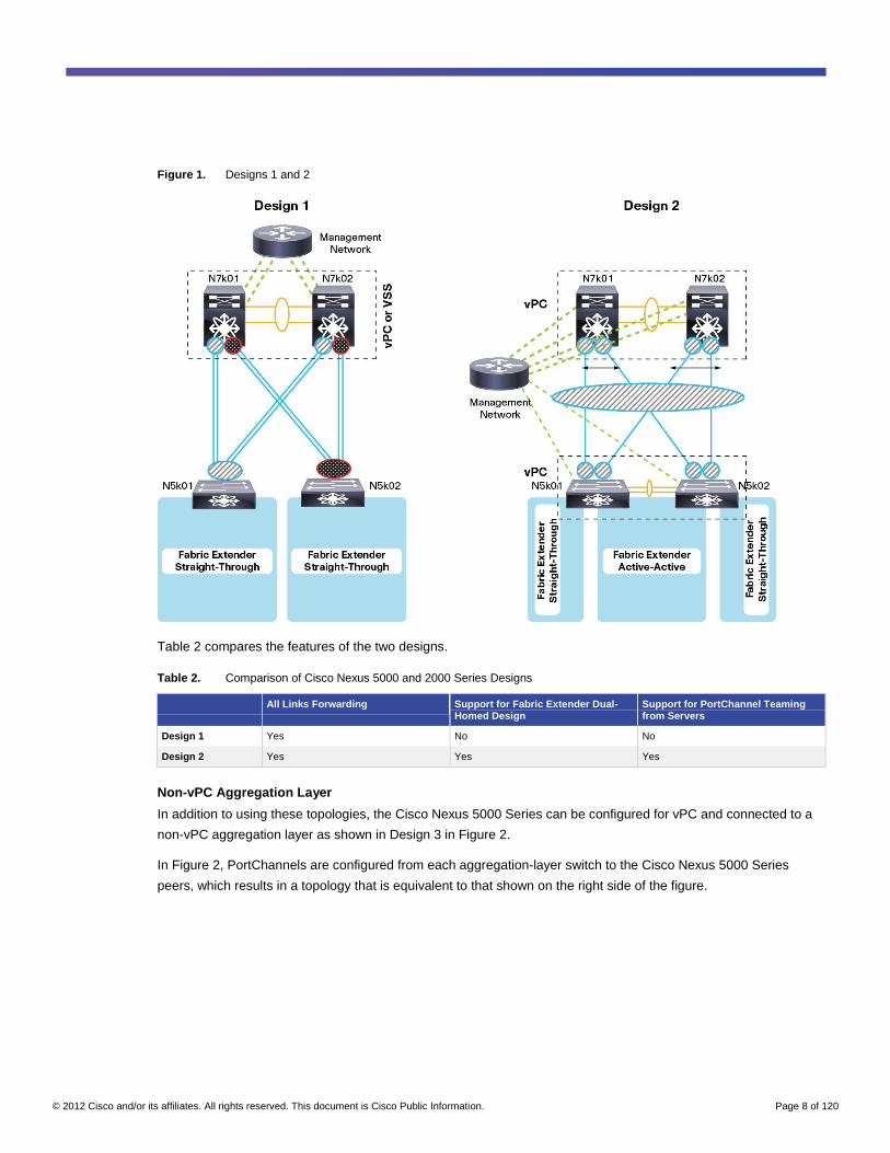
● Design 1, referred to as single-sided vPC, shows the Cisco Nexus 5000 Series supporting a Cisco Nexus
2000 Series Fabric Extender straight-through deployment (also referred to as a fabric extender
single-homed deployment) and dual-connected to Cisco Nexus 7000 Series Switches. In this design, the
Cisco Nexus 7000 Series Switches are configured in vPC mode, and the Cisco Nexus 5000 Series
Switches are not configured in vPC mode.
● Design 2 shows a dual-sided vPC design. In this design, the Cisco Nexus 5000 Series Switches are
configured for vPC. This configuration allows support for host (server) PortChannel teaming with fabric
extender single-homed (also referred to as fabric extender straight-through) or dual-homed (also referred to
as fabric extender active-active) deployment.
© 2012 Cisco and/or its affiliates. All rights reserved. This document is Cisco Public Information. Page 8 of 120
Figure 1. Designs 1 and 2
Table 2 compares the features of the two designs.
Table 2. Comparison of Cisco Nexus 5000 and 2000 Series Designs
All Links Forwarding Support for Fabric Extender Dual-Homed Design
Support for PortChannel Teaming from Servers
Design 1 Yes No No
Design 2 Yes Yes Yes
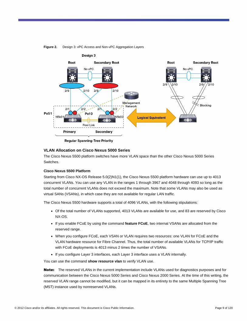
Non-vPC Aggregation Layer
In addition to using these topologies, the Cisco Nexus 5000 Series can be configured for vPC and connected to a
non-vPC aggregation layer as shown in Design 3 in Figure 2.
In Figure 2, PortChannels are configured from each aggregation-layer switch to the Cisco Nexus 5000 Series
peers, which results in a topology that is equivalent to that shown on the right side of the figure.
© 2012 Cisco and/or its affiliates. All rights reserved. This document is Cisco Public Information. Page 9 of 120
Figure 2. Design 3: vPC Access and Non-vPC Aggregation Layers
VLAN Allocation on Cisco Nexus 5000 Series
The Cisco Nexus 5500 platform switches have more VLAN space than the other Cisco Nexus 5000 Series
Switches.
Cisco Nexus 5500 Platform
Starting from Cisco NX-OS Release 5.0(2)N1(1), the Cisco Nexus 5500 platform hardware can use up to 4013
concurrent VLANs. You can use any VLAN in the ranges 1 through 3967 and 4048 through 4093 so long as the
total number of concurrent VLANs does not exceed the maximum. Note that some VLANs may also be used as
virtual SANs (VSANs), in which case they are not available for regular LAN traffic.
The Cisco Nexus 5500 hardware supports a total of 4096 VLANs, with the following stipulations:
● Of the total number of VLANs supported, 4013 VLANs are available for use, and 83 are reserved by Cisco
NX-OS.
● If you enable FCoE by using the command feature FCoE, two internal VSANs are allocated from the
reserved range.
● When you configure FCoE, each VSAN or VLAN requires two resources: one VLAN for FCoE and the
VLAN hardware resource for Fibre Channel. Thus, the total number of available VLANs for TCP/IP traffic
with FCoE deployments is 4013 minus 2 times the number of VSANs.
● If you configure Layer 3 interfaces, each Layer 3 interface uses a VLAN internally.
You can use the command show resource vlan to verify VLAN use.
Note: The reserved VLANs in the current implementation include VLANs used for diagnostics purposes and for
communication between the Cisco Nexus 5000 Series and Cisco Nexus 2000 Series. At the time of this writing, the
reserved VLAN range cannot be modified, but it can be mapped in its entirety to the same Multiple Spanning Tree
(MST) instance used by nonreserved VLANs.
© 2012 Cisco and/or its affiliates. All rights reserved. This document is Cisco Public Information. Page 10 of 120
In Cisco NX-OS 5.1, a fixed range of 80 VLANs is reserved in the VLAN range 3968 to 4047. In Cisco NX-OS 5.2
(which is not available on the Cisco Nexus 5000 Series at the time of this writing), the range of reserved VLANs is
approximately 128 VLANs: http://www.cisco.com/en/US/docs/switches/datacenter/sw/5_x/nx-
os/layer2/configuration/guide/Cisco_Nexus_7000_Series_NX-
OS_Layer_2_Switching_Configuration_Guide_Release_5.x_chapter4.html#con_1273370
Cisco NX-OS 5.2 allows the range of VLANs to be shifted using the following command:
[no] system vlan <start-vlan> reserve
Cisco Nexus 5020 and 5010
Starting from Cisco NX-OS Release 4.1(3)N1, the Cisco Nexus 5000 Series hardware supports 507 concurrent
VLANs (see the discussion of VLANs later in this chapter for details). You can use any VLAN in the ranges 1
through 3967 and 4048 through 4093 as long as the total number of concurrent VLANs does not exceed the
maximum. Note that some VLANs may also be used as VSANs, in which case they are not available for regular
LAN traffic (see the section “VLAN Allocation on Cisco Nexus 5000 Series” earlier in this chapter for details).
The Cisco Nexus 5000 Series hardware supports a total of 512 VLANs, with the following stipulations:
● Of the total number of VLANs supported, 507 VLANs are available for use, and 5 VLANs are used
internally.
● If you enable FCoE by using the command feature FCoE, two internal VSANs are allocated, which brings
the total of available VLANs to 505.
● When you configure FCoE, each VSAN or VLAN requires two resources: one VLAN for FCoE and the
VLAN hardware resource for Fibre Channel. Thus, the total number of available VLANs for TCP/IP traffic
with FCoE deployments is 505 minus 2 times the number of VSANs.
You can use the command show resource vlan to verify VLAN use.
For example, if you have 32 VSANs, and if the software uses 7 VLANs internally to manage fabric extenders and
for internal VSAN purposes, you can use 512 - 32 - 7 = 473 VLANs. In the following example, the user has
configured 14 VLANs, so 459 VLANs are still available:
tc-nexus5k01# show vsan usage
32 vsan configured
tc-nexus5k01# show vlan summary
Number of existing VLANs : 14
Number of existing user VLANs : 14
tc-nexus5k01# show resource vlan
Resource Min Max Used Unused Avail
----------- ----- ----- ------ -------- -------
vlan 16 512 53 0 459
Spanning-Tree Best Practices
The fundamental concept to remember when operating a Cisco Nexus 5000 Series Switch in vPC mode is that
from a spanning-tree perspective, Cisco Nexus 5000 Series vPC pairs appear to operate as a single device on
vPC ports:
● Only the vPC primary link processes Bridge Protocol data units (BPDUs).
● The peer link is never blocking.
© 2012 Cisco and/or its affiliates. All rights reserved. This document is Cisco Public Information. Page 11 of 120
The peer switch feature in Cisco NX-OS changes this behavior. A vPC peer switch is useful exclusively in a vPC
domain that is configured as a root in the spanning-tree topology because it reduces the convergence time needed
when a vPC peer is reloaded. At the time of this writing, this feature is not available in Cisco NX-OS 5.1(3)N1(1) for
the Cisco Nexus 5000 Series because in most topologies a Cisco Nexus 5000 Series device is not the root in the
vPC topology.
The recommended spanning-tree configuration in preparation for a vPC deployment is summarized here:
● Choose the spanning-tree algorithm (this algorithm normally has already been chosen when the
aggregation layer is deployed). Remember that the MST Protocol scales better, and the Rapid per-VSAN
Spanning Tree Plus (PVST+) Protocol may be easier to deploy, vPC deployment brings no real additional
benefit over deploying one separate topology per VLAN.
● In most deployments, you should not modify the priorities on Cisco Nexus 5000 Series Switches deployed
at the access layer.
● Enable spanning-tree pathcost method long to account for the use of 10 Gigabit Ethernet links.
● Host ports can be configured for BPDU filtering to reduce the spanning-tree load, but this recommendation
applies mainly to the Gigabit Ethernet ports on the fabric extender.
● The Bridge Assurance feature should not be enabled on the vPC member ports. Bridge Assurance does not
add much benefit in a PortChannel-based configuration, and it may intervene in certain vPC failure
scenarios in which it is actually less disruptive not to error-disable any port. Also, if you want to take
advantage of In Service Software Upgrade (ISSU) on the Cisco Nexus 5000 Series, you should not enable
Bridge Assurance on any link except the peer link (referred to as the multichassis EtherChannel trunk [MCT]
in the command-line interface [CLI]) on which it is automatically enabled.
● Disable loop guard. In a vPC topology, loop guard does not provide any additional help, and in some failure
scenarios it may actually slow down convergence. If an interface has been configured for loop guard,
remove the configuration with the command (config-if)# spanning-tree guard none.
MST Considerations
If you are using MST, you should preprovision the region configuration at the start. VLAN creation and assignment
to trunk links and host ports can be performed after deployment without any disruption. Region modifications
should be limited to the deployment time to reduce the need for topology recalculations and to avoid Type 1
inconsistencies.
The region configuration (revision number, VLAN-to-instance mapping, etc.) should be copied from the
aggregation-layer device configuration.
If you are using MST, make sure that the VLAN range is identical on Cisco NX-OS devices and devices other than
those that use Cisco NX-OS.
In an MST and vPC deployment, VLANs are typically mapped to one instance only (you do not need two separate
topologies when using vPC). For more information about vPC with MST, please refer to the section “MST and vPC”
later in this chapter.
© 2012 Cisco and/or its affiliates. All rights reserved. This document is Cisco Public Information. Page 12 of 120
Cisco NX-OS devices use VLANs in the ranges 1 through 3967 and 4048 through 4093. Starting from Cisco
NX-OS 5.0(2)N1(1), you can map all VLANs (nonreserved and reserved) to the same instance. This mapping helps
ensure that even if some VLANs are reserved, no artificial MST region appears as a result of the mismatch
between different switches. This mapping change is a result of bug fix CSCtc54335:
spanning-tree mst configuration
name dc1
revision 3
instance 1 vlan 1-4093
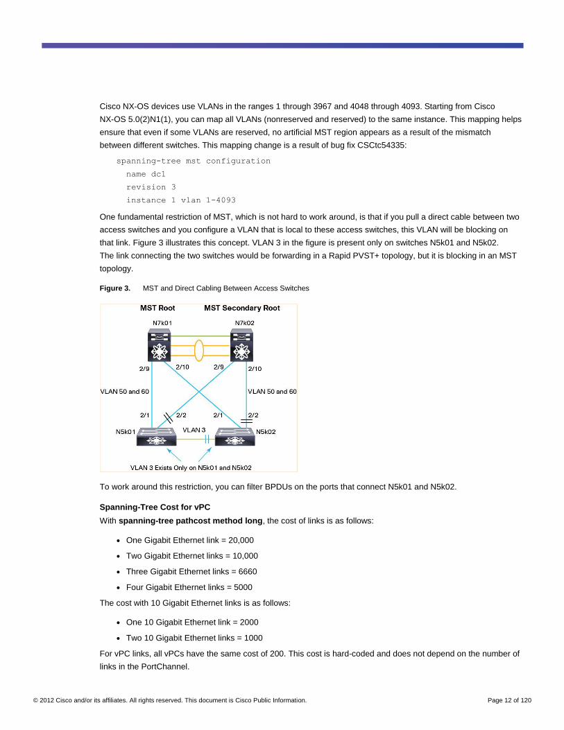
One fundamental restriction of MST, which is not hard to work around, is that if you pull a direct cable between two
access switches and you configure a VLAN that is local to these access switches, this VLAN will be blocking on
that link. Figure 3 illustrates this concept. VLAN 3 in the figure is present only on switches N5k01 and N5k02.
The link connecting the two switches would be forwarding in a Rapid PVST+ topology, but it is blocking in an MST
topology.
Figure 3. MST and Direct Cabling Between Access Switches
To work around this restriction, you can filter BPDUs on the ports that connect N5k01 and N5k02.
Spanning-Tree Cost for vPC
With spanning-tree pathcost method long, the cost of links is as follows:
● One Gigabit Ethernet link = 20,000
● Two Gigabit Ethernet links = 10,000
● Three Gigabit Ethernet links = 6660
● Four Gigabit Ethernet links = 5000
The cost with 10 Gigabit Ethernet links is as follows:
● One 10 Gigabit Ethernet link = 2000
● Two 10 Gigabit Ethernet links = 1000
For vPC links, all vPCs have the same cost of 200. This cost is hard-coded and does not depend on the number of
links in the PortChannel.
© 2012 Cisco and/or its affiliates. All rights reserved. This document is Cisco Public Information. Page 13 of 120
Note: If you need to modify the spanning-tree cost of links in the topology to obtain a certain forwarding
topology, you can use the command spanning-tree cost < cost >.
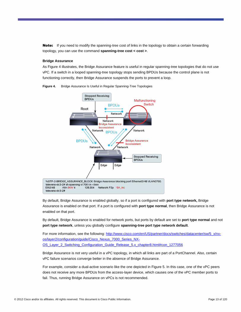
Bridge Assurance
As Figure 4 illustrates, the Bridge Assurance feature is useful in regular spanning-tree topologies that do not use
vPC. If a switch in a looped spanning-tree topology stops sending BPDUs because the control plane is not
functioning correctly, then Bridge Assurance suspends the ports to prevent a loop.
Figure 4. Bridge Assurance Is Useful in Regular Spanning-Tree Topologies
By default, Bridge Assurance is enabled globally, so if a port is configured with port type network, Bridge
Assurance is enabled on that port. If a port is configured with port type normal, then Bridge Assurance is not
enabled on that port.
By default, Bridge Assurance is enabled for network ports, but ports by default are set to port type normal and not
port type network, unless you globally configure spanning-tree port type network default.
For more information, see the following: http://www.cisco.com/en/US/partner/docs/switches/datacenter/sw/5_x/nx-
os/layer2/configuration/guide/Cisco_Nexus_7000_Series_NX-
OS_Layer_2_Switching_Configuration_Guide_Release_5.x_chapter8.html#con_1277056
Bridge Assurance is not very useful in a vPC topology, in which all links are part of a PortChannel. Also, certain
vPC failure scenarios converge better in the absence of Bridge Assurance.
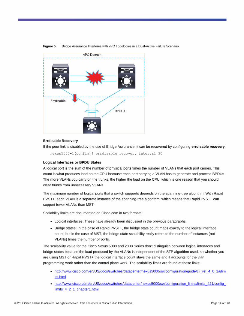
For example, consider a dual-active scenario like the one depicted in Figure 5. In this case, one of the vPC peers
does not receive any more BPDUs from the access-layer device, which causes one of the vPC member ports to
fail. Thus, running Bridge Assurance on vPCs is not recommended.
© 2012 Cisco and/or its affiliates. All rights reserved. This document is Cisco Public Information. Page 14 of 120
Figure 5. Bridge Assurance Interferes with vPC Topologies in a Dual-Active Failure Scenario
Errdisable Recovery
If the peer link is disabled by the use of Bridge Assurance, it can be recovered by configuring errdisable recovery:
nexus5500-1(config)# errdisable recovery interval 30
Logical Interfaces or BPDU States
A logical port is the sum of the number of physical ports times the number of VLANs that each port carries. This
count is what produces load on the CPU because each port carrying a VLAN has to generate and process BPDUs.
The more VLANs you carry on the trunks, the higher the load on the CPU, which is one reason that you should
clear trunks from unnecessary VLANs.
The maximum number of logical ports that a switch supports depends on the spanning-tree algorithm. With Rapid
PVST+, each VLAN is a separate instance of the spanning-tree algorithm, which means that Rapid PVST+ can
support fewer VLANs than MST.
Scalability limits are documented on Cisco.com in two formats:
● Logical interfaces: These have already been discussed in the previous paragraphs.
● Bridge states: In the case of Rapid PVST+, the bridge state count maps exactly to the logical interface
count, but in the case of MST, the bridge state scalability really refers to the number of instances (not
VLANs) times the number of ports.
The scalability value for the Cisco Nexus 5000 and 2000 Series don't distinguish between logical interfaces and
bridge states because the load produced by the VLANs is independent of the STP algorithm used, so whether you
are using MST or Rapid PVST+ the logical interface count stays the same and it accounts for the vlan
programming work rather than the control plane work. The scalability limits are found at these links:
● http://www.cisco.com/en/US/docs/switches/datacenter/nexus5000/sw/configuration/guide/cli_rel_4_0_1a/lim
its.html
● http://www.cisco.com/en/US/docs/switches/datacenter/nexus5000/sw/configuration_limits/limits_421/config_
limits_4_2_1_chapter1.html
© 2012 Cisco and/or its affiliates. All rights reserved. This document is Cisco Public Information. Page 15 of 120
● http://www.cisco.com/en/US/docs/switches/datacenter/nexus5000/sw/configuration_limits/limits_502/Cisco_
Nexus_5000_Series_Configuration_Limits_for_Cisco_NX_OS_Release_502_n1_1_chapter1.html
● http://www.cisco.com/en/US/docs/switches/datacenter/nexus5000/sw/configuration_limits/limits_503/nexus_
5000_config_limits_503.html
● http://www.cisco.com/en/US/docs/switches/datacenter/nexus5000/sw/configuration_limits/limits_513/nexus_
5000_config_limits_513.html
As of Cisco NX-OS 5.0(2)N1(1), the Cisco Nexus 5000 Series supports 12,000 logical interfaces with a maximum
of 4000 network ports (that is, ports that are not spanning-tree port type edge).
Cisco NX-OS 5.0(2)N1(1) on the Cisco Nexus 5500 platform supports a maximum of 12,000 logical interfaces in
any combination.
As of Cisco NX-OS 5.0(3)N1(1a), the Cisco Nexus 5500 platform supports a maximum of 14,500 logical interfaces.
As of Cisco NX-OS 5.1(3)N1(1) the Cisco Nexus 5500 platform supports a maximum of 32,000 logical interfaces
but 16,000 have been verified. In a future release, the code will be verified in order to provide full support for
32,000 logical interfaces.
To increase the scalability of spanning tree in the presence of deployments with a large number of VLANs, you can
configure lacp suspend individual on PortChannels to help ensure that if the PortChannel unbundles, the ports are
put in the suspended state instead of the individual state.
Unidirectional Link Detection
The Unidirectional Link Detection (UDLD) Protocol is described in the Cisco configuration guide as follows: “The
Cisco-proprietary Unidirectional Link Detection (UDLD) protocol allows ports that are connected through fiber
optics or copper (for example, Category 5 cabling) Ethernet cables to monitor the physical configuration of the
cables and detect when a unidirectional link exists. When the switch detects a unidirectional link, UDLD shuts down
the affected LAN port and alerts the user. Unidirectional links can cause a variety of problems, including spanning
tree topology loops”.
This guide can be found at the following link:
http://www.cisco.com/en/US/docs/switches/datacenter/nexus5000/sw/configuration/guide/cli_rel_4_0_1a/BasicEthe
rnet.html#wp1267151.
In Cisco NX-OS, UDLD must be explicitly enabled as a feature and also enabled on a per interface basis:
interface Ethernet1/19
switchport mode trunk
switchport trunk allowed vlan 50,60,100
udld enable
channel-group 21 mode passive
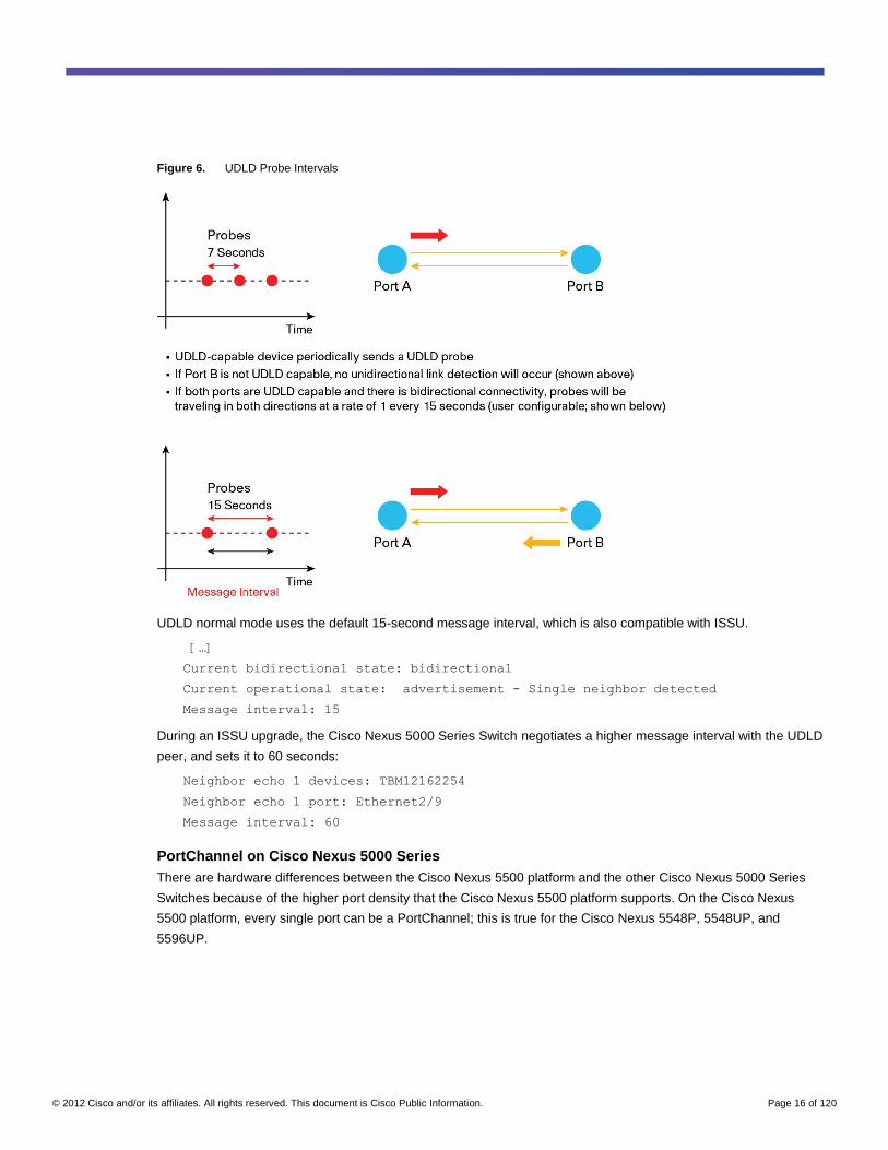
UDLD probes originate at varying intervals depending on the specific state of the UDLD link (Figure 6). On a
bidirectional link with steady state, probes are generated at 15-second intervals by default.
If probes do not arrive because a link became unidirectional, resynchronization is required.
Each port has a cache that expires the hold time (Hold time = 2.5 x Message interval). When the hold time expires,
the port tries resynchronization, and if resynchronization fails, the port is shut down.
© 2012 Cisco and/or its affiliates. All rights reserved. This document is Cisco Public Information. Page 16 of 120
Figure 6. UDLD Probe Intervals
UDLD normal mode uses the default 15-second message interval, which is also compatible with ISSU.
[…]
Current bidirectional state: bidirectional
Current operational state: advertisement - Single neighbor detected
Message interval: 15
During an ISSU upgrade, the Cisco Nexus 5000 Series Switch negotiates a higher message interval with the UDLD
peer, and sets it to 60 seconds:
Neighbor echo 1 devices: TBM12162254
Neighbor echo 1 port: Ethernet2/9
Message interval: 60
PortChannel on Cisco Nexus 5000 Series
There are hardware differences between the Cisco Nexus 5500 platform and the other Cisco Nexus 5000 Series
Switches because of the higher port density that the Cisco Nexus 5500 platform supports. On the Cisco Nexus
5500 platform, every single port can be a PortChannel; this is true for the Cisco Nexus 5548P, 5548UP, and
5596UP.
© 2012 Cisco and/or its affiliates. All rights reserved. This document is Cisco Public Information. Page 17 of 120
Cisco Nexus 5500 Platform
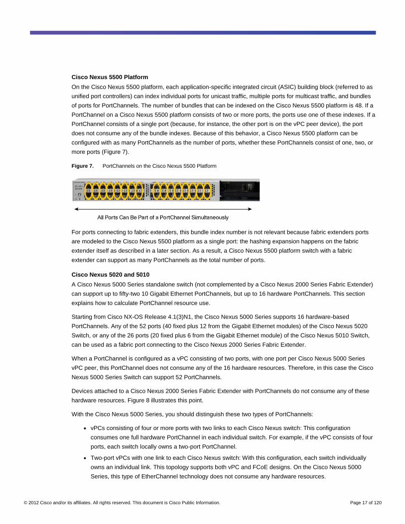
On the Cisco Nexus 5500 platform, each application-specific integrated circuit (ASIC) building block (referred to as
unified port controllers) can index individual ports for unicast traffic, multiple ports for multicast traffic, and bundles
of ports for PortChannels. The number of bundles that can be indexed on the Cisco Nexus 5500 platform is 48. If a
PortChannel on a Cisco Nexus 5500 platform consists of two or more ports, the ports use one of these indexes. If a
PortChannel consists of a single port (because, for instance, the other port is on the vPC peer device), the port
does not consume any of the bundle indexes. Because of this behavior, a Cisco Nexus 5500 platform can be
configured with as many PortChannels as the number of ports, whether these PortChannels consist of one, two, or
more ports (Figure 7).
Figure 7. PortChannels on the Cisco Nexus 5500 Platform
For ports connecting to fabric extenders, this bundle index number is not relevant because fabric extenders ports
are modeled to the Cisco Nexus 5500 platform as a single port: the hashing expansion happens on the fabric
extender itself as described in a later section. As a result, a Cisco Nexus 5500 platform switch with a fabric
extender can support as many PortChannels as the total number of ports.
Cisco Nexus 5020 and 5010
A Cisco Nexus 5000 Series standalone switch (not complemented by a Cisco Nexus 2000 Series Fabric Extender)
can support up to fifty-two 10 Gigabit Ethernet PortChannels, but up to 16 hardware PortChannels. This section
explains how to calculate PortChannel resource use.
Starting from Cisco NX-OS Release 4.1(3)N1, the Cisco Nexus 5000 Series supports 16 hardware-based
PortChannels. Any of the 52 ports (40 fixed plus 12 from the Gigabit Ethernet modules) of the Cisco Nexus 5020
Switch, or any of the 26 ports (20 fixed plus 6 from the Gigabit Ethernet module) of the Cisco Nexus 5010 Switch,
can be used as a fabric port connecting to the Cisco Nexus 2000 Series Fabric Extender.
When a PortChannel is configured as a vPC consisting of two ports, with one port per Cisco Nexus 5000 Series
vPC peer, this PortChannel does not consume any of the 16 hardware resources. Therefore, in this case the Cisco
Nexus 5000 Series Switch can support 52 PortChannels.
Devices attached to a Cisco Nexus 2000 Series Fabric Extender with PortChannels do not consume any of these
hardware resources. Figure 8 illustrates this point.
With the Cisco Nexus 5000 Series, you should distinguish these two types of PortChannels:
● vPCs consisting of four or more ports with two links to each Cisco Nexus switch: This configuration
consumes one full hardware PortChannel in each individual switch. For example, if the vPC consists of four
ports, each switch locally owns a two-port PortChannel.
● Two-port vPCs with one link to each Cisco Nexus switch: With this configuration, each switch individually
owns an individual link. This topology supports both vPC and FCoE designs. On the Cisco Nexus 5000
Series, this type of EtherChannel technology does not consume any hardware resources.
© 2012 Cisco and/or its affiliates. All rights reserved. This document is Cisco Public Information. Page 18 of 120
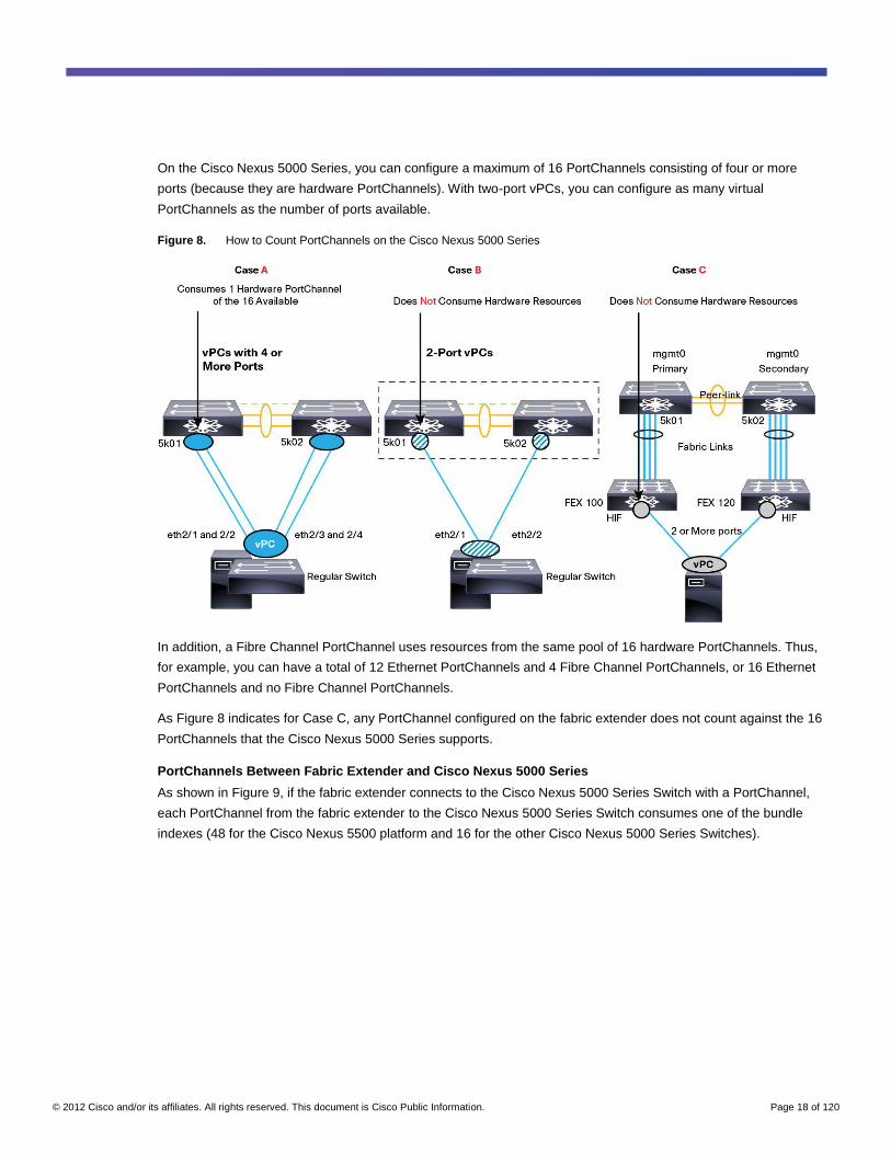
On the Cisco Nexus 5000 Series, you can configure a maximum of 16 PortChannels consisting of four or more
ports (because they are hardware PortChannels). With two-port vPCs, you can configure as many virtual
PortChannels as the number of ports available.
Figure 8. How to Count PortChannels on the Cisco Nexus 5000 Series
In addition, a Fibre Channel PortChannel uses resources from the same pool of 16 hardware PortChannels. Thus,
for example, you can have a total of 12 Ethernet PortChannels and 4 Fibre Channel PortChannels, or 16 Ethernet
PortChannels and no Fibre Channel PortChannels.
As Figure 8 indicates for Case C, any PortChannel configured on the fabric extender does not count against the 16
PortChannels that the Cisco Nexus 5000 Series supports.
PortChannels Between Fabric Extender and Cisco Nexus 5000 Series
As shown in Figure 9, if the fabric extender connects to the Cisco Nexus 5000 Series Switch with a PortChannel,
each PortChannel from the fabric extender to the Cisco Nexus 5000 Series Switch consumes one of the bundle
indexes (48 for the Cisco Nexus 5500 platform and 16 for the other Cisco Nexus 5000 Series Switches).
© 2012 Cisco and/or its affiliates. All rights reserved. This document is Cisco Public Information. Page 19 of 120
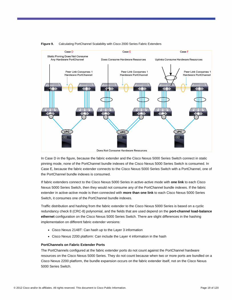
Figure 9. Calculating PortChannel Scalability with Cisco 2000 Series Fabric Extenders
In Case D in the figure, because the fabric extender and the Cisco Nexus 5000 Series Switch connect in static
pinning mode, none of the PortChannel bundle indexes of the Cisco Nexus 5000 Series Switch is consumed. In
Case E, because the fabric extender connects to the Cisco Nexus 5000 Series Switch with a PortChannel, one of
the PortChannel bundle indexes is consumed.
If fabric extenders connect to the Cisco Nexus 5000 Series in active-active mode with one link to each Cisco
Nexus 5000 Series Switch, then they would not consume any of the PortChannel bundle indexes. If the fabric
extender in active-active mode is then connected with more than one link to each Cisco Nexus 5000 Series
Switch, it consumes one of the PortChannel bundle indexes.
Traffic distribution and hashing from the fabric extender to the Cisco Nexus 5000 Series is based on a cyclic
redundancy check 8 (CRC-8) polynomial, and the fields that are used depend on the port-channel load-balance
ethernet configuration on the Cisco Nexus 5000 Series Switch. There are slight differences in the hashing
implementation on different fabric extender versions:
● Cisco Nexus 2148T: Can hash up to the Layer 3 information
● Cisco Nexus 2200 platform: Can include the Layer 4 information in the hash
PortChannels on Fabric Extender Ports
The PortChannels configured at the fabric extender ports do not count against the PortChannel hardware
resources on the Cisco Nexus 5000 Series. They do not count because when two or more ports are bundled on a
Cisco Nexus 2200 platform, the bundle expansion occurs on the fabric extender itself, not on the Cisco Nexus
5000 Series Switch.
© 2012 Cisco and/or its affiliates. All rights reserved. This document is Cisco Public Information. Page 20 of 120
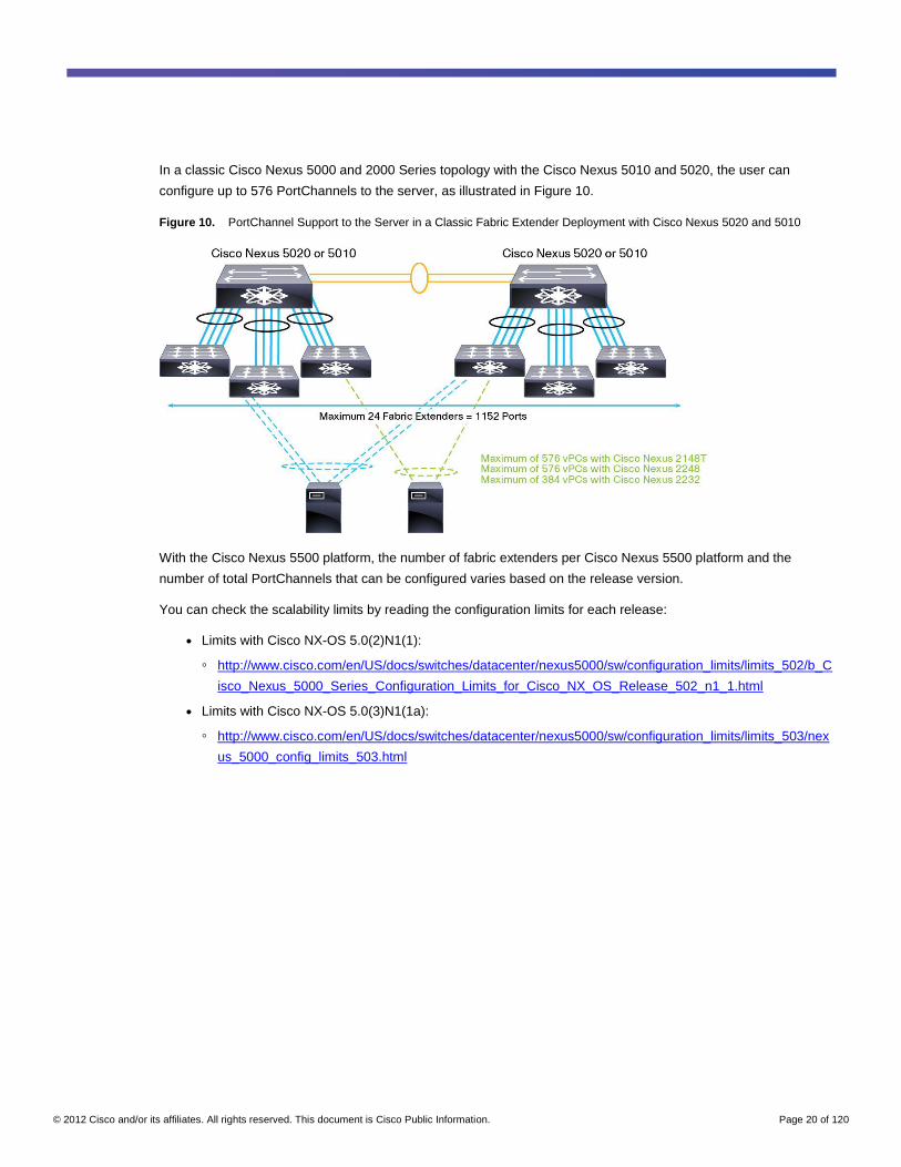
In a classic Cisco Nexus 5000 and 2000 Series topology with the Cisco Nexus 5010 and 5020, the user can
configure up to 576 PortChannels to the server, as illustrated in Figure 10.
Figure 10. PortChannel Support to the Server in a Classic Fabric Extender Deployment with Cisco Nexus 5020 and 5010
With the Cisco Nexus 5500 platform, the number of fabric extenders per Cisco Nexus 5500 platform and the
number of total PortChannels that can be configured varies based on the release version.
You can check the scalability limits by reading the configuration limits for each release:
● Limits with Cisco NX-OS 5.0(2)N1(1):
◦ http://www.cisco.com/en/US/docs/switches/datacenter/nexus5000/sw/configuration_limits/limits_502/b_C
isco_Nexus_5000_Series_Configuration_Limits_for_Cisco_NX_OS_Release_502_n1_1.html
● Limits with Cisco NX-OS 5.0(3)N1(1a):
◦ http://www.cisco.com/en/US/docs/switches/datacenter/nexus5000/sw/configuration_limits/limits_503/nex
us_5000_config_limits_503.html
© 2012 Cisco and/or its affiliates. All rights reserved. This document is Cisco Public Information. Page 21 of 120
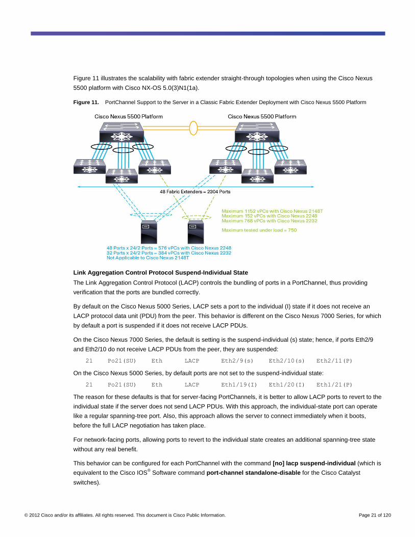
Figure 11 illustrates the scalability with fabric extender straight-through topologies when using the Cisco Nexus
5500 platform with Cisco NX-OS 5.0(3)N1(1a).
Figure 11. PortChannel Support to the Server in a Classic Fabric Extender Deployment with Cisco Nexus 5500 Platform
Link Aggregation Control Protocol Suspend-Individual State
The Link Aggregation Control Protocol (LACP) controls the bundling of ports in a PortChannel, thus providing
verification that the ports are bundled correctly.
By default on the Cisco Nexus 5000 Series, LACP sets a port to the individual (I) state if it does not receive an
LACP protocol data unit (PDU) from the peer. This behavior is different on the Cisco Nexus 7000 Series, for which
by default a port is suspended if it does not receive LACP PDUs.
On the Cisco Nexus 7000 Series, the default is setting is the suspend-individual (s) state; hence, if ports Eth2/9
and Eth2/10 do not receive LACP PDUs from the peer, they are suspended:
21 Po21(SU) Eth LACP Eth2/9(s) Eth2/10(s) Eth2/11(P)
On the Cisco Nexus 5000 Series, by default ports are not set to the suspend-individual state:
21 Po21(SU) Eth LACP Eth1/19(I) Eth1/20(I) Eth1/21(P)
The reason for these defaults is that for server-facing PortChannels, it is better to allow LACP ports to revert to the
individual state if the server does not send LACP PDUs. With this approach, the individual-state port can operate
like a regular spanning-tree port. Also, this approach allows the server to connect immediately when it boots,
before the full LACP negotiation has taken place.
For network-facing ports, allowing ports to revert to the individual state creates an additional spanning-tree state
without any real benefit.
This behavior can be configured for each PortChannel with the command [no] lacp suspend-individual (which is
equivalent to the Cisco IOS® Software command port-channel standalone-disable for the Cisco Catalyst
switches).
© 2012 Cisco and/or its affiliates. All rights reserved. This document is Cisco Public Information. Page 22 of 120
LACP Fast Rate
Starting from Cisco NX-OS 4.2(1)N2(1), you can change the LACP timer rate to modify the duration of the LACP
timeout. Using the lacp rate command, you can set the rate at which LACP control packets are sent to an
LACP-supported interface. You can change the timeout rate from the default rate of 10 seconds with a timeout of
30 seconds to a fast rate of 1 second and with a timeout of 3 seconds.
If the server requires the LACP fast rate, you do not need to configure it on the network interface, because Cisco
NX-OS automatically honors the rate requested by the server. Conversely, if you want the switch to force the
attached server to use the LACP fast rate, you need to configure the fast rate on the switch interface connected to
the server with the command lacp rate fast.
When the server requires Cisco NX-OS to use the fast rate, or when the Cisco NX-OS interface has been explicitly
configured for the fast rate, ISSU is not possible because the timeout is too brief to allow the control plane to be
reloaded during an ISSU operation.
You can verify the timers that an interface is using by entering the following command:
sho lacp interface eth X/Y
Neighbor: 0/0
MAC Address= 0-0-0-0-0-0
System Identifier=0x0,0-0-0-0-0-0
Port Identifier=0x0,0x0
Operational key=0
LACP_Activity=unknown
LACP_Timeout=short Timeout (1s)
Synchronization=IN_SYNC
Collecting=true
Distributing=true
You can verify the rate at which LACP PDUs are sent by entering the following command:
nexus5500-1# show lacp counters interface port-channel 21
PortChannel Hashing Options
The Cisco Nexus 5000 Series offers several load-balancing options, including options to hash on the MAC
address, IP address, and Layer 4 port portions of the packet, as well as the option to choose the hashing algorithm.
The syntax is as follows:
nexus5500-1(config)# port-channel load-balance ethernet source-dest-ip CRC8b
On the Cisco Nexus 5020 and 5010, you can choose between two polynomials: CRC8a and CRC8b. By default,
these Cisco Nexus switches use CRC8a: that is, x8 + x5 + x4 + 1.
On the Cisco Nexus 5500 platform, you can choose among eight polynomials, and by default, CRC8b is used:
● CRC8a = 0x31
● CRC8b = 0x2f
● CRC8c = 0x39
● CRC8d = 0xd5
● CRC8e = 0x4d
© 2012 Cisco and/or its affiliates. All rights reserved. This document is Cisco Public Information. Page 23 of 120
● CRC8f = 0x8d
● CRC8g = 0x9b
PortChannels Summary
In a typical topology, you have to account for the following PortChannels:
● Peer link between Cisco Nexus 5000 Series Switches
● Fabric extender connectivity to the Cisco Nexus 5000 Series
● Uplinks from the Cisco Nexus 5000 Series
● As many PortChannels on the fabric extender ports as needed
As a result, in a typical topology consisting of 12 fabric extenders and vPCs, the PortChannel bundle index use
would be approximately 12 + Peer link + Uplink = 14 PortChannel bundle indexes.
For the Cisco Nexus 5500 platform, with 48 bundle indexes, this calculation is never necessary. For the other
Cisco Nexus 5000 Switches, this number is within the 16 bundle indexes.
Quality of Service on Cisco Nexus 5000 Series
The Cisco Nexus 5000 Series hardware supports eight traffic classes. Two of these traffic classes are used for
control-plane functions such as prioritization of BPDUs, LACP packets, and so on. The total number of traffic
classes available to users is six.
One traffic class is always predefined: class-default.
Depending on the hardware and the software release, the remaining five classes may or may not include a
predefined class for FCoE traffic. For more information, refer to the sections “QoS Group Allocation on Cisco
Nexus 5500 Platform” and “QoS Group Allocation on Cisco Nexus 5020 and 5010 Series” later in this chapter.
There are three main configuration constructs for quality of service (QoS) on the Cisco Nexus 5000 Series:
● class-map and policy-map type qos: These settings are used mainly for classification and marking (for
the differentiated services code point [DSCP]).
● class-map and policy-map type network-qos: These settings are used mainly for network properties such
as queue size, drop or no-drop and maximum transmission units (MTUs), multicast optimization, and
marking (for class of service [CoS]). Up until the network QoS policy is applied, the default QoS group and
buffer carving configuration applies.
● class-map and policy-map type queuing: These settings are used mainly to allocate bandwidth (in
egress) and assign priorities or to communicate the bandwidth allocation to a converged network adapter
(CNA; in ingress).
QoS Group Allocation on Cisco Nexus 5500 Platform
The concept of the QoS group is fundamental to the configuration of QoS on the Cisco Nexus 5000 Series. The
user defines the traffic classification by specifying a matching criteria and the association to one of the QoS groups.
A QoS group is a traffic class, but the numbering of the QoS group does not have a one-to-one relationship with
the CoS. For instance, CoS 5 may be associated with QoS group 1.
Control-plane traffic is associated with either QoS group 6 or 7. Which control-plane traffic goes to which QoS
group is predefined based on matching entries in the TCAM and cannot be modified.
© 2012 Cisco and/or its affiliates. All rights reserved. This document is Cisco Public Information. Page 24 of 120
The class-default value is associated with QoS group 0. No static allocation exists for FCoE traffic.
On the Cisco Nexus 5500 platform, traffic classes and QoS groups are allocated as follows:
● class-default: This is the class for all traffic that is not otherwise classified as belonging to other classes.
This class exists by default; it cannot be removed, but it can be modified.
● Five user-defined traffic classes: Of these, four can be configured as no drop (and one of the no-drop
classes can be used for FCoE traffic).
You can verify the traffic class allocation by using this command:
show policy-map [system]
show policy-map interface brief
By default on the Cisco Nexus 5500 platform, only default policies are applied.
class-map type qos match-any class-default
match any
policy-map type qos default-in-policy
class type qos class-default
set qos-group 0
policy-map type network-qos default-nq-policy
class type network-qos class-default
mtu 1500
multicast-optimize
policy-map type queuing default-out-policy
class type queuing class-default
bandwidth percent 100
As you can see in the default configuration, there is no class reserved for FCoE, which you can also confirm by
looking at the interface configurations:
nexus5500-1# show policy-map int eth1/1
Service-policy (qos) input: default-in-policy
Class-map (qos): class-default (match-any)
Match: any
set qos-group 0
Service-policy (queuing) output: default-out-policy
Class-map (queuing): class-default (match-any)
Match: qos-group 0
bandwidth percent 100
nexus5500-1# show queuing int eth1/1
Ethernet1/1 queuing information:
TX Queuing
qos-group sched-type oper-bandwidth
0 WRR 100
RX Queuing
© 2012 Cisco and/or its affiliates. All rights reserved. This document is Cisco Public Information. Page 25 of 120
qos-group 0
q-size: 470080, HW MTU: 1500 (1500 configured)
drop-type: drop, xon: 0, xoff: 2938
If you want to change the configuration to add support for FCoE, you can just use the predefined policies, which
include both FCoE and class-default policies, and apply them either at the system level or at the interface level.
The following configuration shows the predefined policies that include FCoE:
class-map type qos match-any class-fcoe
match cos 3
class-map type qos match-any class-default
match any
policy-map type qos fcoe-default-in-policy
class type qos class-fcoe
set qos-group 1
class type qos class-default
set qos-group 0
policy-map type network-qos fcoe-default-nq-policy
class type network-qos class-fcoe
pause no-drop
mtu 2158
class type network-qos class-default
mtu 1500
multicast-optimize
policy-map type queuing fcoe-default-in-policy
class type queuing class-fcoe
bandwidth percent 50
class type queuing class-default
bandwidth percent 50
policy-map type queuing fcoe-default-out-policy
class type queuing class-fcoe
bandwidth percent 50
class type queuing class-default
bandwidth percent 50
QoS Group Allocation on Cisco Nexus 5020 and 5010
On the Cisco Nexus 5000 Series Switches other than the Cisco Nexus 5500 platform, control-plane traffic is
associated with either QoS group 6 or 7. Which control-plane traffic goes to which QoS group is predefined based
on matching entries in the TCAM and cannot be modified.
The class-default value is associated with QoS group 0.
On these Cisco Nexus 5000 Series Switches, traffic classes and QoS groups are allocated as follows:
● class-default: This is the class for all traffic that is not otherwise classified as belonging to other classes.
This class exists by default; it cannot be removed, but it can be modified.
● qos-group 1: This is a hard-coded class for FCoE traffic.
© 2012 Cisco and/or its affiliates. All rights reserved. This document is Cisco Public Information. Page 26 of 120
● Four user-defined traffic classes: Of these, two can be no drop (for a total of three no-drop classes in
addition to the FCoE class).
All policy maps, including the one configured by the user, have class-fcoe.
You can verify the traffic class allocation by using this command:
show policy-map [system]
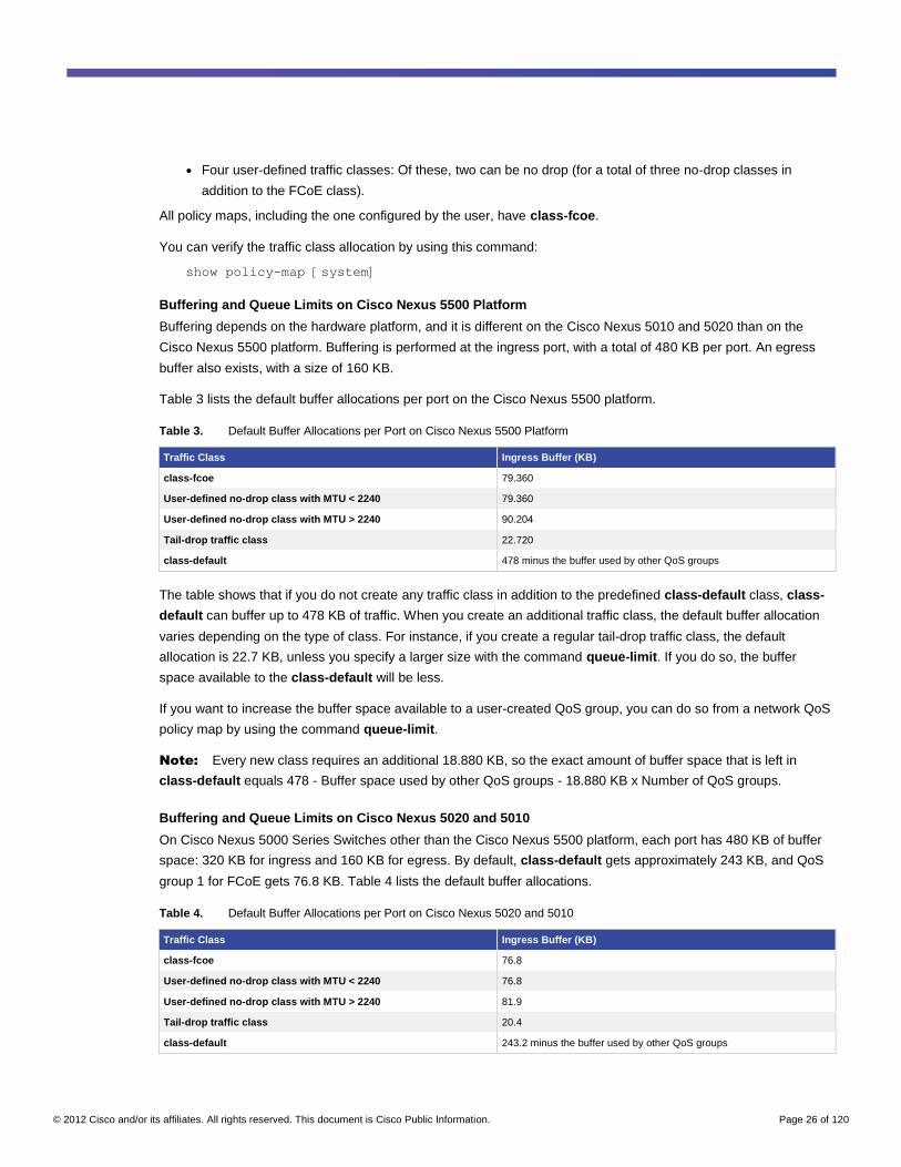
Buffering and Queue Limits on Cisco Nexus 5500 Platform
Buffering depends on the hardware platform, and it is different on the Cisco Nexus 5010 and 5020 than on the
Cisco Nexus 5500 platform. Buffering is performed at the ingress port, with a total of 480 KB per port. An egress
buffer also exists, with a size of 160 KB.
Table 3 lists the default buffer allocations per port on the Cisco Nexus 5500 platform.
Table 3. Default Buffer Allocations per Port on Cisco Nexus 5500 Platform
Traffic Class Ingress Buffer (KB)
class-fcoe 79.360
User-defined no-drop class with MTU < 2240 79.360
User-defined no-drop class with MTU > 2240 90.204
Tail-drop traffic class 22.720
class-default 478 minus the buffer used by other QoS groups
The table shows that if you do not create any traffic class in addition to the predefined class-default class, class-
default can buffer up to 478 KB of traffic. When you create an additional traffic class, the default buffer allocation
varies depending on the type of class. For instance, if you create a regular tail-drop traffic class, the default
allocation is 22.7 KB, unless you specify a larger size with the command queue-limit. If you do so, the buffer
space available to the class-default will be less.
If you want to increase the buffer space available to a user-created QoS group, you can do so from a network QoS
policy map by using the command queue-limit.
Note: Every new class requires an additional 18.880 KB, so the exact amount of buffer space that is left in
class-default equals 478 - Buffer space used by other QoS groups - 18.880 KB x Number of QoS groups.
Buffering and Queue Limits on Cisco Nexus 5020 and 5010
On Cisco Nexus 5000 Series Switches other than the Cisco Nexus 5500 platform, each port has 480 KB of buffer
space: 320 KB for ingress and 160 KB for egress. By default, class-default gets approximately 243 KB, and QoS
group 1 for FCoE gets 76.8 KB. Table 4 lists the default buffer allocations.
Table 4. Default Buffer Allocations per Port on Cisco Nexus 5020 and 5010
Traffic Class Ingress Buffer (KB)
class-fcoe 76.8
User-defined no-drop class with MTU < 2240 76.8
User-defined no-drop class with MTU > 2240 81.9
Tail-drop traffic class 20.4
class-default 243.2 minus the buffer used by other QoS groups
© 2012 Cisco and/or its affiliates. All rights reserved. This document is Cisco Public Information. Page 27 of 120
If you want to increase the buffer space available to a user-created QoS group, you can do so from a network QoS
policy map by using the command queue-limit.
Note: Every new class requires an additional 18.880 KB, so the exact amount of buffer space that is left in
class-default equals 243.2 KB - Buffer space used by other QoS groups - 18.880 KB x Number of QoS groups.
Classification
You need to classify the traffic to perform any QoS operation on it. To do so, you need to put each traffic type in a
QoS group.
You can configure the classification in two ways:
● At the global level
● At the per-interface level
You can match several fields in the incoming frame to decide how to classify the traffic; for instance:
● You can match the CoS
● You can match the IP precedence or DSCP field
● You can match the packet with an access control list (ACL)
Note: For releases prior to Cisco NX-OS 5.0(2)N1(1), the default matching criterion was the equivalent of
“match any.” Starting from Cisco NX-OS 5.0(2)N1(1), this criterion is user configurable as either match-any or
match-all; the default is match-all.
You can assign traffic to a QoS group as follows:
● You can assign traffic to any QoS group, from QoS group 2 through QoS group 5.
● Starting from Cisco NX-OS 5.0(2)N1(1), you can assign traffic to QoS group 1.
● Although you can use and modify class-default (QoS group 0), you cannot explicitly assign a traffic class to
Qos group 0. QoS group 0 is a catch-all for whatever does not match any of the other traffic classes.
● The classification entries are looked up in the order that they appear in the configuration. Rules are
evaluated in the order of definition, and traffic is classified based on the first rule that matches.
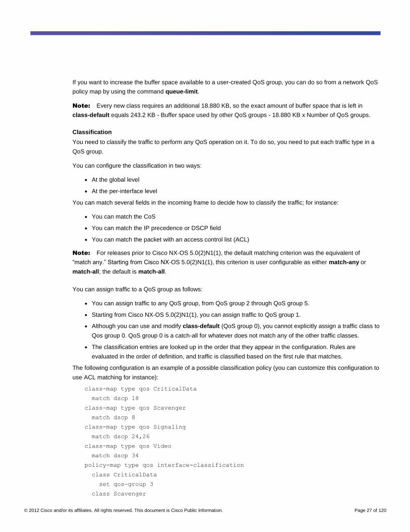
The following configuration is an example of a possible classification policy (you can customize this configuration to
use ACL matching for instance):
class-map type qos CriticalData
match dscp 18
class-map type qos Scavenger
match dscp 8
class-map type qos Signaling
match dscp 24,26
class-map type qos Video
match dscp 34
policy-map type qos interface-classification
class CriticalData
set qos-group 3
class Scavenger
© 2012 Cisco and/or its affiliates. All rights reserved. This document is Cisco Public Information. Page 28 of 120
set qos-group 2
class Signaling
set qos-group 4
class Video
set qos-group 4
You can then apply the policy map on a per-interface basis as follows:
interface eth1/1 - 32
service-policy type qos input interface-classification
You can also map the classification configuration globally as follows:
system qos
service-policy type qos input interface-classification
The two configurations may seem equivalent to each other, but depending on the hardware configuration, they may
not be.
For instance, if a fabric extender is attached to the Cisco Nexus 5000 Series Switch, a DSCP-based classification
will not be applied. Although the Cisco Nexus 2200 platform hardware can classify traffic based on ACLs, the
software does not allow this yet. As a result, a systemwide classification policy with classification based on ACLs or
DSCP would be rejected by the fabric extender but still applied on the Cisco Nexus 5000 Series ports.
So if you are using a Cisco Nexus 5000 Series Switch with a fabric extender, the following approach is currently
recommended:
● If you define a CoS-based classification policy, you can define it systemwide.
● If you define an ACL-based or DSCP-based classification policy, you should define it per interface.
● You can also have a global classification policy based on CoS, and a more specific classification policy
based on the ACL or DSCP and applied per interface (the more specific classification policy will override the
global one).
Another way to classify traffic is to define untagged cos on a per interface basis. This classification still requires a
mapping from the CoS to the QoS group.
The untagged cos classification does not override the CoS of a packet; it uniquely applies to untagged traffic. If
you need to assign traffic from a given interface to a different CoS than the one with which it is tagged, you need to
use an ACL in the classification policy.
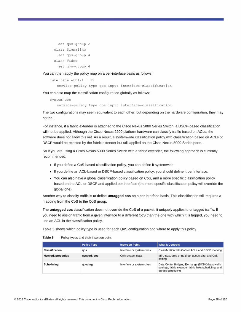
Table 5 shows which policy type is used for each QoS configuration and where to apply this policy.
Table 5. Policy types and their insertion point
Policy Type Insertion Point What It Controls
Classification qos Interface or system class Classification with CoS or ACLs and DSCP marking
Network properties network-qos Only system class MTU size, drop or no drop, queue size, and CoS setting
Scheduling queuing Interface or system class Data Center Bridging Exchange (DCBX) bandwidth settings, fabric extender fabric links scheduling, and egress scheduling
© 2012 Cisco and/or its affiliates. All rights reserved. This document is Cisco Public Information. Page 29 of 120
Marking
With the Cisco Nexus 5500 platform, you can mark traffic with both a CoS and a DSCP value. With the other Cisco
Nexus 5000 Series Switches, you can mark traffic only with CoS. Marking is performed as follows:
● For DSCP marking, you need to use policy-map type qos.
● For CoS marking, you need to use policy-map type network-qos.
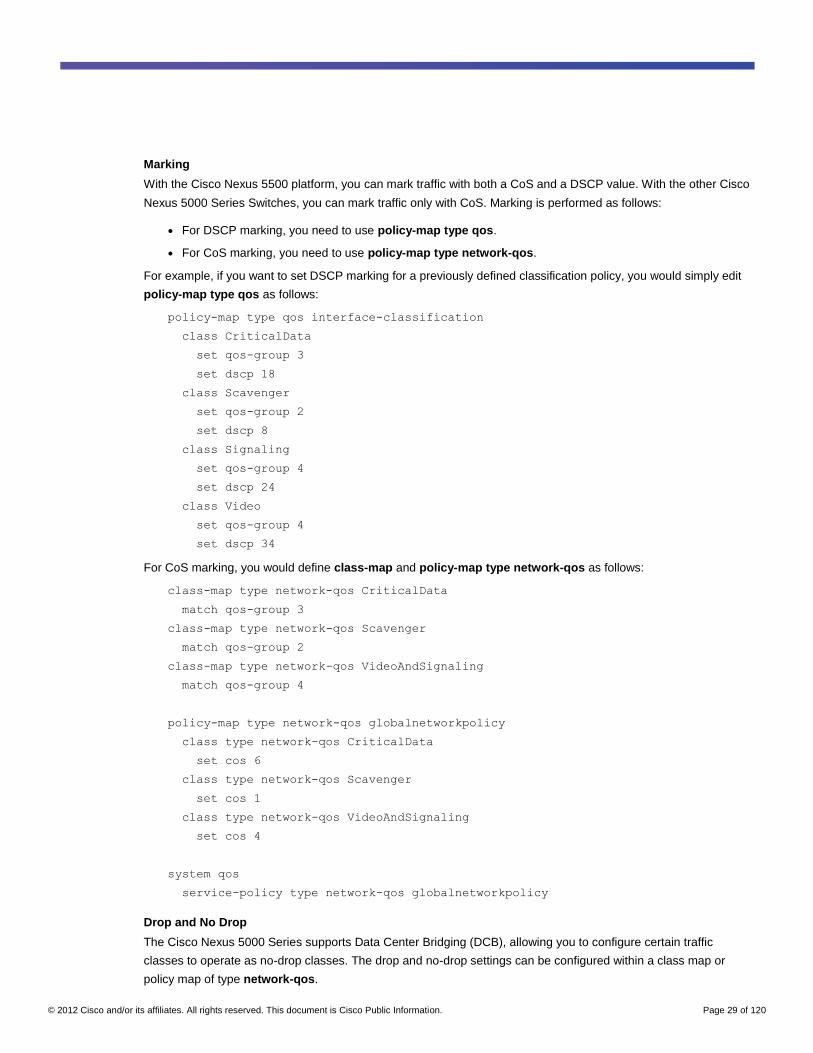
For example, if you want to set DSCP marking for a previously defined classification policy, you would simply edit
policy-map type qos as follows:
policy-map type qos interface-classification
class CriticalData
set qos-group 3
set dscp 18
class Scavenger
set qos-group 2
set dscp 8
class Signaling
set qos-group 4
set dscp 24
class Video
set qos-group 4
set dscp 34
For CoS marking, you would define class-map and policy-map type network-qos as follows:
class-map type network-qos CriticalData
match qos-group 3
class-map type network-qos Scavenger
match qos-group 2
class-map type network-qos VideoAndSignaling
match qos-group 4
policy-map type network-qos globalnetworkpolicy
class type network-qos CriticalData
set cos 6
class type network-qos Scavenger
set cos 1
class type network-qos VideoAndSignaling
set cos 4
system qos
service-policy type network-qos globalnetworkpolicy
Drop and No Drop
The Cisco Nexus 5000 Series supports Data Center Bridging (DCB), allowing you to configure certain traffic
classes to operate as no-drop classes. The drop and no-drop settings can be configured within a class map or
policy map of type network-qos.
© 2012 Cisco and/or its affiliates. All rights reserved. This document is Cisco Public Information. Page 30 of 120
For instance, if you want to make the class VideoAndSignaling a no-drop class, you can configure it as follows:
class-map type network-qos CriticalData
match qos-group 3
class-map type network-qos Scavenger
match qos-group 2
class-map type network-qos VideoAndSignaling
match qos-group 4
policy-map type network-qos globalnetworkpolicy
class type network-qos VideoAndSignaling
pause no-drop
The number of no-drop classes that can be configured depends on whether you are using the Cisco Nexus 5010 or
5020 or the Cisco Nexus 5500 platform.
On the Cisco Nexus 5500 platform, the hardware supports up to four no-drop traffic classes; the exact number of
configurable ones varies by release.
On the Cisco Nexus 5010 and 5020, the following rules apply:
● If the total number of QoS groups is less than or equal to four (including QoS group 0 and QoS group 1 if
defined), then the user can configure three total no-drop classes (of which one is used by QoS group 1 for
FCoE if QoS group 1 is defined).
● If the total number of QoS groups is more than four, a total of two no-drop classes can be defined, of which
one is used by QoS group 1 for FCoE if QoS group 1 is defined).
More About type network-qos Policies
You can use type network-qos polices for the following configurations:
● Setting up the MTU for a traffic class
● Setting up drop or no-drop behavior
● Setting the queue limit for a traffic class
The network QoS policy can be applied only under system qos; it cannot be configured under an individual
interface.
Egress Scheduling and Priority Queuing
To determine the bandwidth allocation for the traffic from the Cisco Nexus 5000 Series to the wire, you need to use
policy-map type queuing, which allows you to define the bandwidth percentage used by each traffic class.
This policy map is applied in the egress direction.
The ingress policy map is applied for two main purposes:
● For DCBX, to set up the proper bandwidth allocation on the CNA
● To program the bandwidth allocation on the fabric extender for traffic from the host ports to the network
ports (often referred to as H2N traffic)
The following is a sample configuration for the egress queuing policy:
class-map type queuing CriticalData
match qos-group 3
© 2012 Cisco and/or its affiliates. All rights reserved. This document is Cisco Public Information. Page 31 of 120
class-map type queuing Scavenger
match qos-group 2
class-map type queuing VideoAndSignaling
match qos-group 4
policy-map type queuing globalqueuingpolicy
class type queuing CriticalData
bandwidth percent 6
class type queuing Scavenger
bandwidth percent 1
class type queuing VideoAndSignaling
bandwidth percent 20
system qos
service-policy type queuing output globalqueuingpolicy
Something is missing from the preceding configuration. If you apply it on a Cisco Nexus 5010 or 5020, the
configuration is rejected. The reason for the rejection is that the default allocation for class-default is 50 percent of
the bandwidth, and the default allocation for class-fcoe is also 50 percent of the bandwidth.
You can fix the configuration by adding the class-default settings (class-default exists by default):
policy-map type queuing globalqueuingpolicy
class type queuing CriticalData
bandwidth percent 6
class type queuing Scavenger
bandwidth percent 1
class type queuing VideoAndSignaling
bandwidth percent 20
class type queuing class-default
bandwidth percent 10
Jumbo Frames
Jumbo frames are an important feature in 10 Gigabit Ethernet data centers because they allow servers to fully use
the available bandwidth with less CPU utilization than with regular Ethernet frames.
The jumbo frames implementation on the Cisco Nexus 5000 Series is designed to allow multiple MTUs for different
traffic classes on the same link.
Global Jumbo Frames Configuration
Jumbo frames on the Cisco Nexus 5000 Series are configured as part of the QoS configuration for system classes.
Jumbo frames configuration is performed as follows:
policy-map type network-qos jumbo
class type network-qos class-default
mtu 9000
system qos
© 2012 Cisco and/or its affiliates. All rights reserved. This document is Cisco Public Information. Page 32 of 120
service-policy type network-qos jumbo
Starting from Cisco NX-OS 4.2(1)N1(1), the semantics of the MTU configuration have changed. Prior to this
release, the MTU specified the full frame size (the maximum payload size plus Ethernet headers). Starting from
Cisco NX-OS 4.2(1)N1(1), the MTU size specified in the configuration refers to the Ethernet payload only. The
release notes state the following:
“The meaning of MTU configuration has changed from pre-4.2(1)N1(1) releases to 4.2(1)N1(1) release. In pre-
4.2(1)N1(1) releases, the configured MTU included the Ethernet payload and Ethernet headers. In 4.2(1)N1(1)
release, the configured MTU includes only the Ethernet payload and not the Ethernet headers. When
upgrading/downgrading between pre-4.2(1)N1(1) and 4.2(1)N1(1) releases, NX-OS will automatically convert the
configuration to address this semantic change by adding/subtracting 38 to the MTU to address the Ethernet header
size.”
For the full release notes, see the following link:
http://www.cisco.com/en/US/docs/switches/datacenter/nexus5000/sw/release/notes/Rel_4_2_1_N1_1/Nexus5000_
Release_Notes_4_2_1_N1_1.html
The show queuing interface command displays the frame size that is allowed on a given interface as a result of
the MTU configuration command.
Per-Interface Jumbo Frames Configuration on Cisco Nexus 5000 Series Interfaces
Besides defining jumbo frames globally, you may need to define jumbo frames for specific interfaces. The policy
map type network cannot be mapped for an interface; it can be applied only systemwide. To work around this
restriction, you can define the type network policy map at the system level and then apply the policy map type qos
at the interface level. By using this approach, you can make sure that only selected interfaces are associated with
the QoS group that is used for jumbo frames.
Here is an example of how to implement this configuration. This example shows how to enable jumbo frames on
interfaces eth1/1 and 1/2.
IP access-list IP_traffic
Permit ip any any
Class-map type qos Class_jumbo
Match ip access-group name IP_traffic
Policy-map type qos Policy_Jumbo
Class type qos Class_jumbo
Set qos-group 5
Class-map type network-qos Class_jumbo
Match qos-group 5
Policy-map type network Policy_NQ_Jumbo
Class type network-qos Class_jumbo
Mtu 9000
System qos
Service-policy type network-qos Policy_NQ_Jumbo
Interface eth1/1-2
Service-policy type qos input Policy_Jumbo
© 2012 Cisco and/or its affiliates. All rights reserved. This document is Cisco Public Information. Page 33 of 120
If you need to restore the default MTU, just restore the default QoS policy (cut and paste the following):
system qos
service-policy type qos input default-in-policy
service-policy type network-qos default-nq-policy
service-policy type queuing output default-out-policy
service-policy type queuing input default-in-policy
Note: When using vPC, make sure to configure jumbo frames on both Cisco Nexus 5000 Series Switches to
avoid global inconsistencies.
Per-Interface Jumbo Frames Configuration on Fabric Extender Interfaces
At the time of this writing, fabric extenders do not have software support to program the hardware to perform ACL-
based classification on the fabric extender itself (ACL classification is performed after the traffic reaches the Cisco
Nexus 5000 Series Switch).
Because of this lack of support, you need to use a CoS-based configuration to apply a jumbo frame configuration
to specific interfaces on the fabric extender.
For instance, if you specify that QoS group 5 uses a jumbo MTU, you may want to use a particular CoS (for
simplicity, this chapter uses CoS 5) that is mapped to that QoS group.
To implement this configuration, you need to do the following:
● Define untagged cos 5 under the fabric extender interface configuration to make sure that a given fabric
extender interface is mapped to the particular QoS group that enables jumbo frames.
● Globally configure a policy map of type qos to match CoS 5 and assign it to QoS group 5.
● Apply the policy map type qos globally (you cannot apply it under the fabric extender interface).
● Make sure that the network QoS policy that matches the QoS group (for instance, qos-group 5) is also
applied systemwide.
An example of this configuration is shown here:
class-map type qos match-all jumbo-per-port
match cos 5
policy-map type qos jumbo-per-port
class jumbo-per-port
set qos-group 5
class-map type network-qos cos-to-jumbo
match qos-group 5
policy-map type network-qos mp-nq-jumbo-per-port
class type network-qos cos-to-jumbo
mtu 9000
class type network-qos class-default
multicast-optimize
system qos
service-policy type queuing input fcoe-default-in-policy
service-policy type queuing output fcoe-default-out-policy
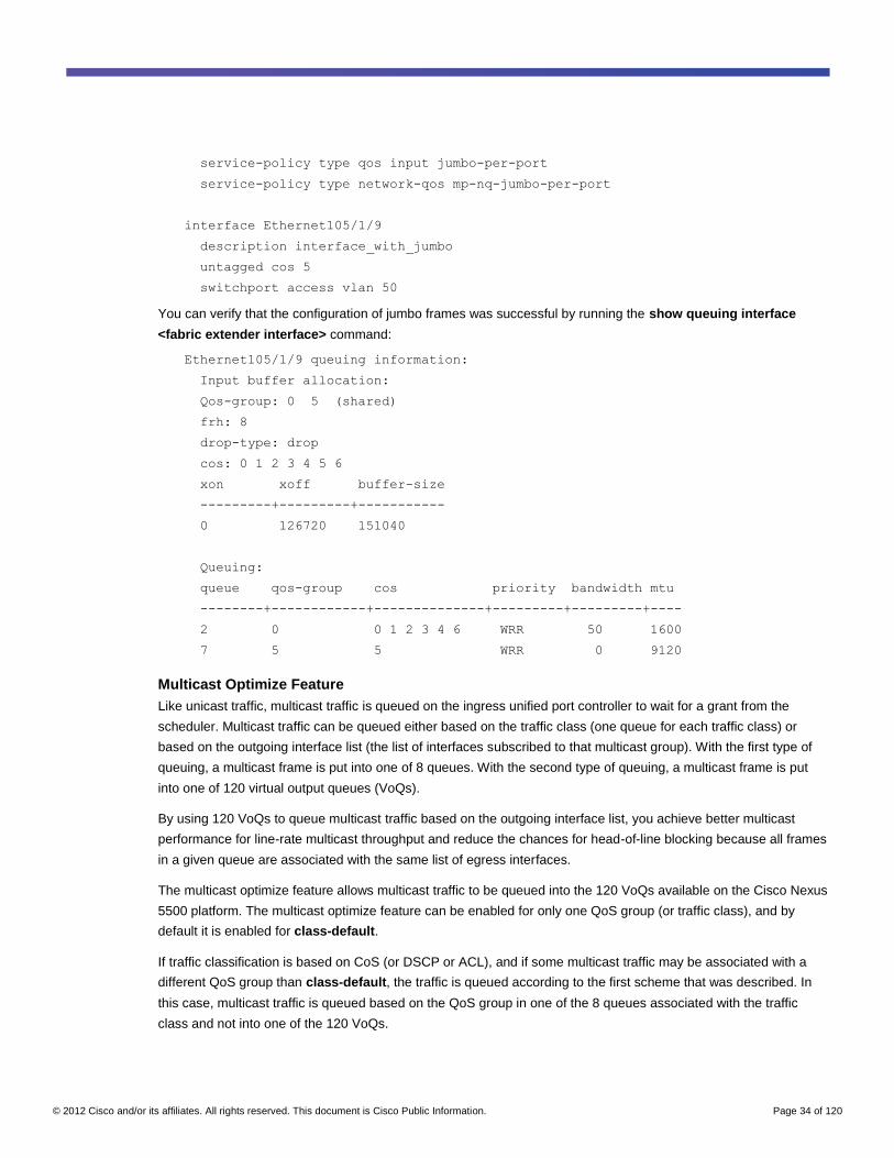
© 2012 Cisco and/or its affiliates. All rights reserved. This document is Cisco Public Information. Page 34 of 120
service-policy type qos input jumbo-per-port
service-policy type network-qos mp-nq-jumbo-per-port
interface Ethernet105/1/9
description interface_with_jumbo
untagged cos 5
switchport access vlan 50
You can verify that the configuration of jumbo frames was successful by running the show queuing interface
<fabric extender interface> command:
Ethernet105/1/9 queuing information:
Input buffer allocation:
Qos-group: 0 5 (shared)
frh: 8
drop-type: drop
cos: 0 1 2 3 4 5 6
xon xoff buffer-size
---------+---------+-----------
0 126720 151040
Queuing:
queue qos-group cos priority bandwidth mtu
--------+------------+--------------+---------+---------+----
2 0 0 1 2 3 4 6 WRR 50 1600
7 5 5 WRR 0 9120
Multicast Optimize Feature
Like unicast traffic, multicast traffic is queued on the ingress unified port controller to wait for a grant from the
scheduler. Multicast traffic can be queued either based on the traffic class (one queue for each traffic class) or
based on the outgoing interface list (the list of interfaces subscribed to that multicast group). With the first type of
queuing, a multicast frame is put into one of 8 queues. With the second type of queuing, a multicast frame is put
into one of 120 virtual output queues (VoQs).
By using 120 VoQs to queue multicast traffic based on the outgoing interface list, you achieve better multicast
performance for line-rate multicast throughput and reduce the chances for head-of-line blocking because all frames
in a given queue are associated with the same list of egress interfaces.
The multicast optimize feature allows multicast traffic to be queued into the 120 VoQs available on the Cisco Nexus
5500 platform. The multicast optimize feature can be enabled for only one QoS group (or traffic class), and by
default it is enabled for class-default.
If traffic classification is based on CoS (or DSCP or ACL), and if some multicast traffic may be associated with a
different QoS group than class-default, the traffic is queued according to the first scheme that was described. In
this case, multicast traffic is queued based on the QoS group in one of the 8 queues associated with the traffic
class and not into one of the 120 VoQs.
© 2012 Cisco and/or its affiliates. All rights reserved. This document is Cisco Public Information. Page 35 of 120
If you want to change this behavior and help ensure that all multicast traffic is queued based on the outgoing
interface list and not based on the traffic class, you can define a new traffic classification criteria that matches
multicast traffic only and define multicast optimize on this traffic class.
The multicast optimize feature can be enabled on only one class, so if you want to enable it for a class other than
class-default, you have to disable it on that class.
For instance, you can define the following classification and network QoS policy:
policy-map type qos new-classification-policy
class-map type qos class-ip-multicast
set qos-group 2
class type qos class-default
set qos-group 0
policy-map type network-qos new-nq-policy
class type network-qos class-ip-multicast
multicast-optimize
class type network-qos class-default
no multicast-optimize
By defining this classification and network policy, you can help ensure that all multicast traffic is queued based on
the outgoing interface list instead of the traffic class (for example, CoS). With the configuration shown here, one of
the six QoS groups is used for the multicast classification, and one is used by class-default, thus leaving four QoS
groups for further classification.
Multicast on Cisco Nexus 5000 Series
The Cisco Nexus 5000 Series are Layer 2 switches, and consequently Internet Group Management Protocol
(IGMP) snooping governs the multicast forwarding behavior of these switches. Well-known multicast best practices
apply in the case of the Cisco Nexus 5000 Series, summarized at the following link:
http://www.cisco.com/en/US/prod/collateral/iosswrel/ps6537/ps6552/ps6592/whitepaper_c11-474791.html.
IGMP Snooping Theory of Operations
Without IGMP snooping, Layer 2 forwarding of multicast frames would result in the flooding of every multicast
frame. This flooding then would degrade the network performance by turning a switch into the equivalent of a hub,
consuming bandwidth on network links, and degrading server performance.
IGMP snooping is the feature that allows Layer 2 frames to be forwarded only to the switch ports on which
receivers are subscribed to a given multicast group. By constraining the forwarding of multicast frames to only the
hosts that need to receive them, the link bandwidth on the other hosts is not unnecessarily consumed, and the
CPU of the hosts that did not subscribe does not have to drop unneeded frames.
Basic IGMP Operations
If no host sent any IGMP report, a multicast frame sent to a Layer 2 switch (configured for IGMP snooping) would
just be dropped (this is true for all multicast frames except the link-local frames). For a multicast frame to be
forwarded, either IGMP snooping must be disabled, and as a result the frame is flooded, or IGMP must be enabled,
and hosts have to explicitly join multicast groups if they expect to receive traffic.
© 2012 Cisco and/or its affiliates. All rights reserved. This document is Cisco Public Information. Page 36 of 120
Note: Never disable IGMP snooping. If you need to manually configure entries for multicast group subscribers
that cannot send IGMP messages, use the CLI command switch(config-vlan)# ip igmp snooping static-group
group-ip-addr [source source-ip-addr] interface 1 interface 2 etc… under the VLAN configuration mode.
Hosts join multicast groups either by sending an unsolicited IGMP report message or sending an IGMP report
message in response to a general query from a multicast router. These join messages from the potential receivers
are intercepted by the switch CPU and used to populate the Layer 2 forwarding table associated with the port from
which the join message arrived.
For example, if a host sends an IGMP join message (an unsolicited membership report) for the multicast group
239.1.0.1, the switch programs the equivalent Layer 2 MAC address (which is the rightmost 23 bits of the IP
address concatenated with the multicast organizationally unique identifier [OUI] 01.00.5) 01.00.5e.01.00.01 to be
associated with the port from which the frame came.
If multiple hosts join the multicast group, the MAC address is associated with multiple ports. The list of ports with
which the multicast MAC address is associated is referred to as the outgoing interface list or fanout.
When looking at the Layer 2 forwarding table of a network that has multicast traffic, you would find several MAC
addresses of type 01.00.5e.x.x.x associated with various outgoing interface lists.
Router Multicast Addresses Flooding
IGMP snooping does not constrain Layer 2 multicasts generated by routing protocols.
In general, multicast addresses in the 224.0.0.x range are considered link-local multicast addresses. They are used
for protocol discovery and are flooded to every port.
If multicast frames are flooded to all ports despite the presence of IGMP snooping, this is because these frames
are:
● Link-local frames (224.0.0.x range)
● Multicast IP frames whose MAC addresses are overloaded with the MAC addresses of the link-local
multicast addresses (frames with IP x.0.0.x or x.128.0.x)
Because of the overloading of multiple IP multicast addresses to the same MAC address, if you use a x.0.0.x or
x.128.0.x multicast IP address, it will not be constrained by IGMP snooping.
IGMP Querier
A switched network configured for IGMP snooping does not forward a multicast frame unless an explicit IGMP
report for that group came from a Layer 2 port (with the exception explained in the previous section).
For IGMP snooping to operate correctly, an IGMP querier needs to send periodic IGMP queries, so that the
receivers will respond and send IGMP membership reports. These reports determine which switch ports receive
the multicast traffic for a particular group.
If Protocol-Independent Multicast (PIM) is not enabled on at least one router in the switch environment, then one
router or switch needs to be configured as the IGMP querier. This configuration is accomplished with the ip igmp
snooping querier command. To configure this command, under the VLAN configuration (not the interface VLAN),
specify an IP address and then specify the querier configuration as follows:
nexus5500-1(config-vlan)# ip igmp snooping querier A.B.C.D
Note: The IGMP querier does not require configuration of a switch virtual interface (SVI).
© 2012 Cisco and/or its affiliates. All rights reserved. This document is Cisco Public Information. Page 37 of 120
Note: For more information about IGMP scalability, please refer to the “Multicast Scalability” section later in this
chapter.
In some deployments, server pairs or other similar devices need to see the same copy of the traffic. If these
devices do not respond to IGMP queries, instead of disabling IGMP, which is strongly discouraged because it
causes flooding and consumes bandwidth, you can configure static IGMP entries with the following command:
ip igmp snooping static-group <multicast IP address> interface ethernet 1/1
ethernet 1/2
Multicast Routers
Multicast routers (mrouters) actively query VLANs for potential receivers. To do this, they send IGMP queries, and
a Layer 2 switch forwards general queries from mrouters to all ports on the VLAN.
A Layer 2 switch intercepts the IGMP reports from the hosts and sends them (in an aggregated fashion) to the
multicast router.
Also when a host originates a multicast frame, the switch must send it to all the hosts that subscribed to the
multicast group as well as to the multicast router. Unknown IP multicast traffic is sent to mrouter ports, and if there
are no mrouter ports, the traffic is dropped.
The switch knows where the multicast router is located (that is, to which ports it must forward multicast frames and
IGMP reports) by snooping the following traffic:
● IGMP membership query sent to 01-00-5e-00-00-01
● PIMv1 hello sent to 01-00-5e-00-00-02
● PIMv2 hello sent to 01-00-5e-00-00-0d
● Distance Vector Multicast Routing Protocol (DVMRP) probes sent to 01-00-5e-00-04
● Multicast Open Shortest Path First (MOSPF) message sent to 01-00-5e-00-05 or 06
If a switch does not receive any of these messages, no mrouter ports get programmed in the layer 2 forwarding
table, and as a result a multicast stream is only forwarded to the layer 2 ports which subscribed to the multicast
group. If no IGMP report was previously received by the switch or no PIM, query packet, the multicast frame is
simply not forwarded to any port.
If you need to configure the mrouter port manually, you can use the following command:
ip igmp snooping mrouter interface <interface> vlan <vlan-id>
IGMP versions
Several versions of IGMP exist: versions1, 2, and 3. All versions support PIM Sparse Mode (PIM-SM) and
bidirectional PIM (BiDir PIM). IGMPv3 also supports Source-Specific Multicast (SSM), allowing a host to join a
group for a specific source only (S,G).
The destination IP address for the multicast reports and queries varies depending on the IGMP version. With
IGMPv3, hosts send the reports to the specific multicast address 224.0.0.22. IMGPv1 and v2 send the report to the
same IP address as for the group to which the report refers (for example, for a join message to 239.1.0.1, the
report is sent to 239.1.0.1).
IGMP queries from the router are addressed to 224.0.0.1 in IGMPv3, or in the case of group-specific queries, to the
group IP address.
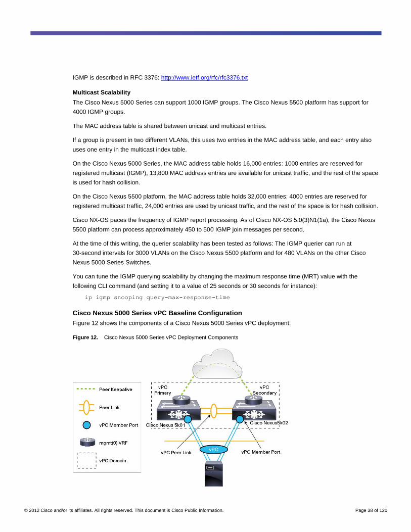
© 2012 Cisco and/or its affiliates. All rights reserved. This document is Cisco Public Information. Page 38 of 120
IGMP is described in RFC 3376: http://www.ietf.org/rfc/rfc3376.txt
Multicast Scalability
The Cisco Nexus 5000 Series can support 1000 IGMP groups. The Cisco Nexus 5500 platform has support for
4000 IGMP groups.
The MAC address table is shared between unicast and multicast entries.
If a group is present in two different VLANs, this uses two entries in the MAC address table, and each entry also
uses one entry in the multicast index table.
On the Cisco Nexus 5000 Series, the MAC address table holds 16,000 entries: 1000 entries are reserved for
registered multicast (IGMP), 13,800 MAC address entries are available for unicast traffic, and the rest of the space
is used for hash collision.
On the Cisco Nexus 5500 platform, the MAC address table holds 32,000 entries: 4000 entries are reserved for
registered multicast traffic, 24,000 entries are used by unicast traffic, and the rest of the space is for hash collision.
Cisco NX-OS paces the frequency of IGMP report processing. As of Cisco NX-OS 5.0(3)N1(1a), the Cisco Nexus
5500 platform can process approximately 450 to 500 IGMP join messages per second.
At the time of this writing, the querier scalability has been tested as follows: The IGMP querier can run at
30-second intervals for 3000 VLANs on the Cisco Nexus 5500 platform and for 480 VLANs on the other Cisco
Nexus 5000 Series Switches.
You can tune the IGMP querying scalability by changing the maximum response time (MRT) value with the
following CLI command (and setting it to a value of 25 seconds or 30 seconds for instance):
ip igmp snooping query-max-response-time
Cisco Nexus 5000 Series vPC Baseline Configuration
Figure 12 shows the components of a Cisco Nexus 5000 Series vPC deployment.
Figure 12. Cisco Nexus 5000 Series vPC Deployment Components
© 2012 Cisco and/or its affiliates. All rights reserved. This document is Cisco Public Information. Page 39 of 120
The following list provides a summary of vPC configuration best practices:
● Connect the two Cisco Nexus 5000 Series Switches through redundant 10 Gigabit Ethernet links to form the
peer link between vPC peers. No specific benefit is gained by separating vPC and non-vPC VLANs. This
link carries both vPC VLANs and non-vPC VLANs. When the peer link is configured, Bridge Assurance is
automatically enabled on this link. The peer link is not used as a health verification mechanism on its own;
another link is necessary for the vPC to converge and to be initiated: the peer keepalive link. The vPC peer
link alone does not replace the peer keepalive link.
● The peer keepalive is an out-of-band monitoring mechanism that is used for vPC peers to arbitrate roles
and to resolve peer link failures. You should configure the peer keepalive connectivity either through the
mgmt0 interface or a SVI and a separate port. For example, each Cisco Nexus 5000 Series mgmt0
interface may already be connected to the management network, in which case the vPC configuration can
simply use the existing connectivity for peer keepalive purposes.
● Unlike on the Cisco Nexus 7000 Series, on the Cisco Nexus 5000 Series direct connectivity of the peer
keepalive through mgmt0 from one vPC peer is an acceptable practice for testing, although routing over the
management network (or any out-of-band network) is still preferred for deployment.
● The peer keepalive traffic should never be carried on a VLAN over the peer link; such a configuration would
make the peer keepalive useless.
● The default configuration on the Cisco Nexus 7000 Series makes ports go into the suspended state if they
cannot negotiate LACP. The default configuration on the Cisco Nexus 5000 Series makes port go into the
individual state if they cannot negotiate LACP, which provides better connectivity at the cost of greater load
on spanning tree. Because of this trade-off, you may want to configure PortChannels on the Cisco Nexus
5000 Series that connect to the upstream switch with lacp suspend individual to suspend ports that are
connected to a non-LACP port.
● In a double-sided vPC configuration (Design 2 in Figure 1), make sure that the vPC domain ID differs from
that of the upstream vPC or VSS device.
● If the Cisco Nexus 5000 Series Switch connects to a Cisco Catalyst platform, you may have to disable the
EtherChannel misconfiguration guard on the Cisco Catalyst switch unless you are using Cisco NX-OS
4.2(0) or higher. With earlier Cisco NX-OS releases, EtherChannel misconfiguration guard would disable
the Cisco Catalyst links upon a dual active failure on the Cisco Nexus 5000 Series Switch (that is, a failure
of both the peer link and the peer keepalive connections).
● Bridge Assurance (spanning-tree port type network) should not be enabled on the vPC member ports, as
illustrated in Figure 13. Bridge Assurance can be used on the peer link (which is the default).
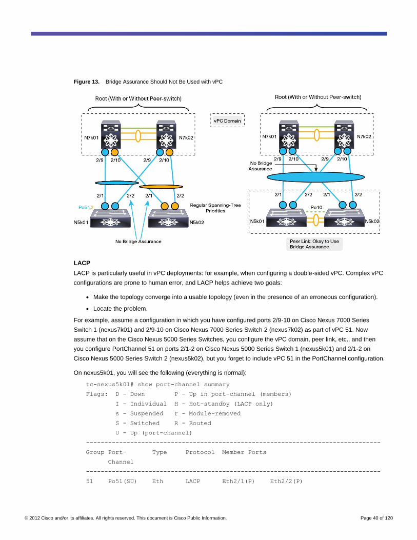
© 2012 Cisco and/or its affiliates. All rights reserved. This document is Cisco Public Information. Page 40 of 120
Figure 13. Bridge Assurance Should Not Be Used with vPC
LACP
LACP is particularly useful in vPC deployments: for example, when configuring a double-sided vPC. Complex vPC
configurations are prone to human error, and LACP helps achieve two goals:
● Make the topology converge into a usable topology (even in the presence of an erroneous configuration).
● Locate the problem.
For example, assume a configuration in which you have configured ports 2/9-10 on Cisco Nexus 7000 Series
Switch 1 (nexus7k01) and 2/9-10 on Cisco Nexus 7000 Series Switch 2 (nexus7k02) as part of vPC 51. Now
assume that on the Cisco Nexus 5000 Series Switches, you configure the vPC domain, peer link, etc., and then
you configure PortChannel 51 on ports 2/1-2 on Cisco Nexus 5000 Series Switch 1 (nexus5k01) and 2/1-2 on
Cisco Nexus 5000 Series Switch 2 (nexus5k02), but you forget to include vPC 51 in the PortChannel configuration.
On nexus5k01, you will see the following (everything is normal):
tc-nexus5k01# show port-channel summary
Flags: D - Down P - Up in port-channel (members)
I - Individual H - Hot-standby (LACP only)
s - Suspended r - Module-removed
S - Switched R - Routed
U - Up (port-channel)
--------------------------------------------------------------------------------
Group Port- Type Protocol Member Ports
Channel
--------------------------------------------------------------------------------
51 Po51(SU) Eth LACP Eth2/1(P) Eth2/2(P)
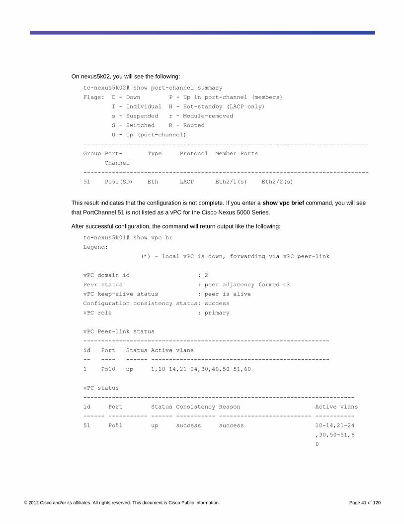
© 2012 Cisco and/or its affiliates. All rights reserved. This document is Cisco Public Information. Page 41 of 120
On nexus5k02, you will see the following:
tc-nexus5k02# show port-channel summary
Flags: D - Down P - Up in port-channel (members)
I - Individual H - Hot-standby (LACP only)
s - Suspended r - Module-removed
S - Switched R - Routed
U - Up (port-channel)
--------------------------------------------------------------------------------
Group Port- Type Protocol Member Ports
Channel
--------------------------------------------------------------------------------
51 Po51(SD) Eth LACP Eth2/1(s) Eth2/2(s)
This result indicates that the configuration is not complete. If you enter a show vpc brief command, you will see
that PortChannel 51 is not listed as a vPC for the Cisco Nexus 5000 Series.
After successful configuration, the command will return output like the following:
tc-nexus5k01# show vpc br
Legend:
(*) - local vPC is down, forwarding via vPC peer-link
vPC domain id : 2
Peer status : peer adjacency formed ok
vPC keep-alive status : peer is alive
Configuration consistency status: success
vPC role : primary
vPC Peer-link status
---------------------------------------------------------------------
id Port Status Active vlans
-- ---- ------ --------------------------------------------------
1 Po10 up 1,10-14,21-24,30,40,50-51,60
vPC status
----------------------------------------------------------------------------
id Port Status Consistency Reason Active vlans
------ ----------- ------ ----------- -------------------------- -----------
51 Po51 up success success 10-14,21-24
,30,50-51,6
0
© 2012 Cisco and/or its affiliates. All rights reserved. This document is Cisco Public Information. Page 42 of 120
vPC Domain ID
When configuring the vPC domain ID in double-sided vPC deployments, you should make sure that this ID differs
from the one used by a neighboring vPC pair. The reason for this distinction is that the system ID is derived from
the MAC address of the switch, and for vPC this MAC address is derived from the domain ID. As a result, in a
back-to-back vPC configuration, if the neighboring switches use the same domain ID, a system ID conflict may
arise in the LACP negotiation, leading to an unsuccessful LACP negotiation.
Autorecovery and vPC Reload Restore
Prior to a reload restore or autorecovery operation, if a functioning vPC switch that was part of a vPC domain was
reloaded, and if after the reload operation the vPC peer was missing, vPC ports would not become active.
The vPC reload restore feature was introduced in Cisco NX-OS 5.0(2). With the vPC reload restore feature, when
the peer keepalive is down, or when both the peer and peer keepalive links are lost, the vPC primary can activate
new vPCs ports.
In addition, with the reload restore feature, a vPC peer can reload, and after the reload operation, if no vPC peer
exists (a condition that is detected by a timer), the user can create vPCs on the standalone vPC peer.
Upon reload, Cisco NX-OS starts a user-configurable timer (with a default setting of 240 seconds). If the peer link
port comes up physically, or if the peer keepalive is functional, the timer is stopped, and the device waits for the
peer adjacency to form. If at timer expiration no peer keepalive or peer link packets have been received, Cisco NX-
OS assumes the primary role. The software reinitializes the vPCs, activating the local ports. Because there are no
peers, the consistency check for the local vPC ports is bypassed.
The timer is user configurable and defines the length of time that the standalone vPC device waits to detect a vPC
peer. If at the timer expiration no peer keepalive or peer link packets have been received, the software reinitializes
the vPCs, activating the local ports. Because there are no peers, the consistency check for the local vPC ports is
bypassed.
The autorecovery feature in Cisco NX-OS 5.0(2)N2(1) was introduced to address the same scenario as just
described as well as the following scenario: In the event of peer link failure, the vPC secondary switch checks
whether the primary switch is still alive. The vPC secondary switch suspends its vPC member ports after it confirms
that the primary switch is alive. If the primary switch fails afterward, this failure leads to a peer keepalive failure,
and without autorecovery, the vPC secondary switch would keep the vPC member ports in the suspended state.
Starting from Cisco NX-OS 5.0(2)N2(1), if the user configures autorecovery the secondary switch will assume vPC
primary role and bring up a vPC member port after it misses three keepalive message from the vPC primary
switch.
Autorecovery is strongly recommended in all configurations, and it supersedes the reload restore feature.
To configure autorecovery, you need to enter the vPC domain configuration mode:
vpc domain 10
peer-keepalive destination <Peer IP>
auto-recovery reload-delay <value>
© 2012 Cisco and/or its affiliates. All rights reserved. This document is Cisco Public Information. Page 43 of 120
Peer Link
Because of its importance, the peer link should always be configured in a redundant manner. The loss of the peer
link is recovered in a way that does not cause split subnets or continuous flooding.
The peer link carries the control traffic used to synchronize MAC address tables and IGMP entries. In a dual-active
scenario traffic for existing MAC entries and existing multicast groups, members would continue flowing correctly. If
a new unicast MAC address was learned after the loss of the peer link, traffic destined to this MAC address would
cause flooding. If a new IGMP report was generated after the loss of the peer link, proper IGMP snooping
processing would be triggered on one vPC peer only. As a result, multicast traffic arriving on the other vPC peer
would be dropped.
For these reasons, when the peer link is lost, vPC shuts down vPC member ports on the operational secondary
switch to avoid a dual-active scenario, as illustrated in Figure 14.
In Figure 14, Host1, Host2, and Host 3 are connected to the Cisco Nexus 5000 and 2000 Series devices,
respectively, with a PortChannel in a vPC configuration.
Upon failure of the peer link, the vPC secondary switch checks whether the vPC primary switch is still alive (by
using the heartbeat verification mechanism of the peer keepalive link) and correctly shuts down the vPC member
port on the secondary Cisco Nexus 5000 Series Switch and associated Cisco Nexus 2000 Series Fabric
Extenders.
Note: The vPC secondary device shuts down the vPC ports when the peer link fails. Before performing this
action, the vPC secondary device needs to make sure that the vPC primary device is still alive. This verification is
based on the reception of peer keepalive messages. If these are not received, the vPC ports on the secondary
device are not shut down.
Because of this behavior, unicast and multicast traffic continue flowing correctly through the vPC primary device.
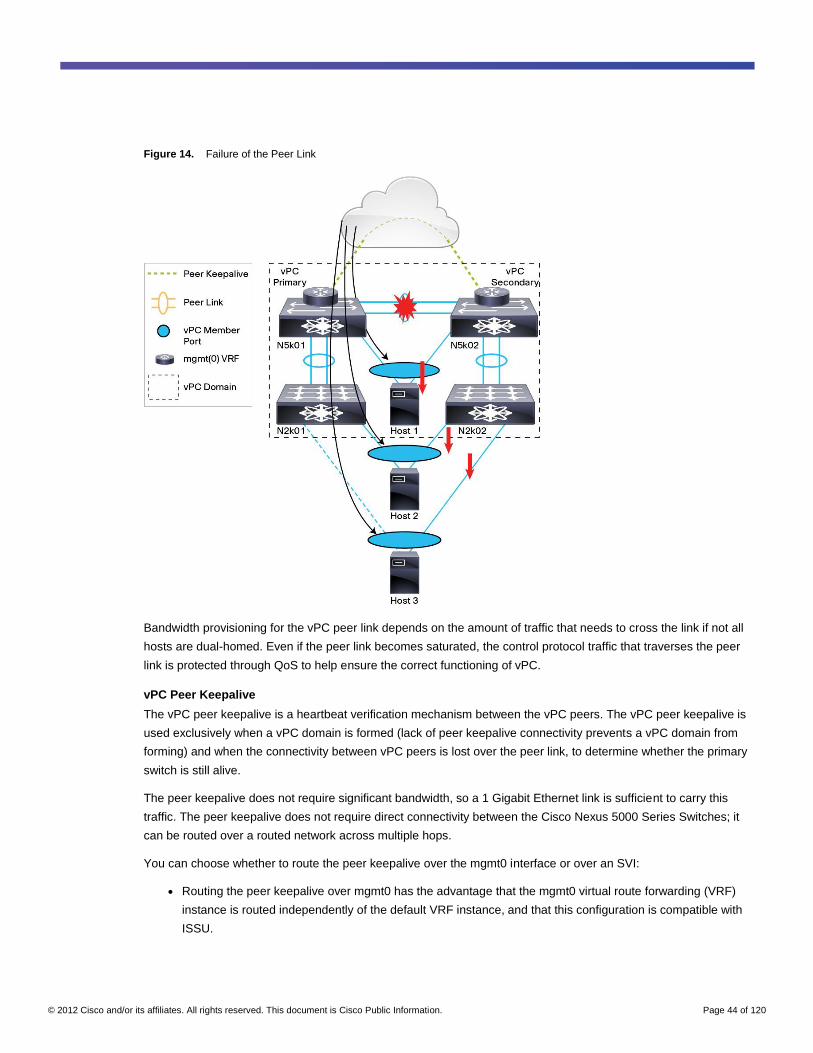
© 2012 Cisco and/or its affiliates. All rights reserved. This document is Cisco Public Information. Page 44 of 120
Figure 14. Failure of the Peer Link
Bandwidth provisioning for the vPC peer link depends on the amount of traffic that needs to cross the link if not all
hosts are dual-homed. Even if the peer link becomes saturated, the control protocol traffic that traverses the peer
link is protected through QoS to help ensure the correct functioning of vPC.
vPC Peer Keepalive
The vPC peer keepalive is a heartbeat verification mechanism between the vPC peers. The vPC peer keepalive is
used exclusively when a vPC domain is formed (lack of peer keepalive connectivity prevents a vPC domain from
forming) and when the connectivity between vPC peers is lost over the peer link, to determine whether the primary
switch is still alive.
The peer keepalive does not require significant bandwidth, so a 1 Gigabit Ethernet link is sufficient to carry this
traffic. The peer keepalive does not require direct connectivity between the Cisco Nexus 5000 Series Switches; it
can be routed over a routed network across multiple hops.
You can choose whether to route the peer keepalive over the mgmt0 interface or over an SVI:
● Routing the peer keepalive over mgmt0 has the advantage that the mgmt0 virtual route forwarding (VRF)
instance is routed independently of the default VRF instance, and that this configuration is compatible with
ISSU.
© 2012 Cisco and/or its affiliates. All rights reserved. This document is Cisco Public Information. Page 45 of 120
● Routing the peer keepalive from an SVI over a regular front-panel port provides the advantage that you can
connect Cisco Nexus 5000 Series Switches back to back if you want to do so; it also provides additional
verification of the health of the ASICs through which the peer keepalive flows. It provides the disadvantage
that the peer keepalive is routed according to the information contained in the default VRF instance (which
may cause the traffic to use the peer link instead of a different path); in addition, ISSU is not compatible with
this configuration.
When using a Layer 3 card for routing on the Cisco Nexus 5500 platform, you can allocate a VRF instance just for
this purpose and associate the SVI or a Layer 3 interface for the purpose of carrying the peer keepalive.
In most deployments, routing the peer keepalive over mgmt0 is the best option. With a Layer 3 card, routing the
peer keepalive over an SVI with a dedicated VRF instance is the next best option.
The configuration of the peer keepalive using mgmt0 is as follows:
interface mgmt0
ip address 10.51.35.18/27
vpc domain 2
peer-keepalive destination 10.51.35.17 source 10.51.35.18
The following is a sample configuration of the peer keepalive using an SVI:
! Port connecting Nexus5k01 to Nexus 5k02 directly
interface Ethernet1/31
description direct-peer-keepalive
switchport access vlan 3
spanning-tree port type edge
! Clearing the peer-link from the VLAN that is used for the peer-keepalive
! If using MST you need to configure BPDU filtering to prevent this port from
blocking
interface Po10
switchport trunk allowed vlan remove 3
! Defining the SVI that is used by the peer keepalive, in this case this SVI
! is defined within the VRF default
interface Vlan3
no ip redirects
ip address 10.50.3.10/31
no shutdown
! configuration of the peer-keepalive information with the associated vrf
vpc domain 2
peer-keepalive destination 10.50.3.11 source 10.50.3.10 vrf default
Note: When using a Layer 3 card on the Cisco Nexus 5500 platform, you can create a dedicated VRF instance
for the peer keepalive and hence specify this newly created VRF instance in the peer keepalive configuration.
Most failures in the vPC topology are recovered within 1 or 2 seconds. Peer link failure and recovery is the most
disruptive type of failure, in part because the vPC secondary device needs to determine whether or not to shut
down vPC ports on the basis of whether or not keepalive messages are received from the vPC primary switch.
© 2012 Cisco and/or its affiliates. All rights reserved. This document is Cisco Public Information. Page 46 of 120
To reduce the traffic loss for single-attached devices (which may be attached to the vPC primary device), you may
want to tune the peer keepalive timer as follows:
nexus5500-1(config-vpc-domain)# peer-keepalive destination <destination IP>
interval <ms>
Split-Brain Scenarios
When two vPC peers become completely disconnected, they cannot synchronize either unicast or multicast MAC
address entries. This lack of synchronization can cause flooding for unicast traffic and traffic drops for multicast
traffic.
To reduce traffic loss when two vPC peers are disconnected, the peer keepalive connection is used by the vPC
peers. If the peer link is missing and the peer keepalive connectivity is still present, the vPC primary switch keeps
the vPCs active, while the vPC secondary switch shuts down the vPC member ports. This approach helps ensure
uninterrupted traffic connectivity across the vPC primary switch path.
If both the vPC peer link and peer keepalive become disconnected, all vPCs are kept active because this failure is
undistinguishable from the loss of a vPC peer.
This scenario works fine in double-sided vPC topologies, but it can introduce loops in designs like the one shown in
Figure 2.In addition, spanning-tree disputes can occur in this particular design when both the peer link and the peer
keepalive are absent.
Split-Brain Scenarios After a Reload Operation
A particular case of a split-brain scenario occurs when the peer keepalive connectivity disappears, and afterwards
the vPC peers are reloaded.
Initially when peer keepalive connectivity disappears, vPC keeps functioning, because the keepalive is not strictly
necessary for the correct forwarding of frames in a vPC topology.
If the vPCs peers then subsequently reload, when they become active, the lack of peer keepalive connectivity
prevents the vPC domain from forming. This scenario would keep the vPC ports down, unless autorecovery is
configured.
In this particular case, if autorecovery is configured, the vPC peers bring up their vPC ports, without bringing up the
vPC peer link. The result is a split-brain scenario, which can cause loops and spanning-tree disputes as described
in the previous section.
Cisco Nexus 5000 Series vPC Advanced Considerations
Configuration Consistency for PortChannels
The Ethernet PortChannel capability allows links to be bundled to form a single entity if certain compatibility
conditions are met. The following is a list of conditions that are verified before ports can form a regular PortChannel
(this list refers to regular PortChannels, not vPCs). Members must:
● Have the same port mode configured
● Have the same speed configured; if they are configured with speed set to automatic, they have to negotiate
the same speed when they become active, and if a member negotiates a different speed, it will be
suspended
● Have the same MTU value configured
© 2012 Cisco and/or its affiliates. All rights reserved. This document is Cisco Public Information. Page 47 of 120
● Have the same duplex mode configured
● Have the same Ethernet layer (switch port or no switch port) configured
● Not be Switched Port Analyzer (SPAN) ports
● Have the same storm control configured
● Have the same flow control configured
● Have common capabilities
● Be switching ports (Layer 2)
● Have the same port access VLAN
● Have the same port native VLAN
● Have the same port-allowed VLAN list
vPC Consistency Checks
Like regular PortChannels, vPCs are subject to consistency checks and compatibility checks. During a compatibility
check, one vPC peer conveys configuration information to the other vPC peer to verify that vPC member ports can
actually form a PortChannel. For example, if two ports that are going to join the channel carry a different set of
VLANs, a misconfiguration occurs.
Depending on the severity of the misconfiguration, vPC may either warn the user (Type 2 misconfiguration) or
suspend the PortChannel (Type 1 misconfiguration). In the specific case of a VLAN mismatch, only the VLAN that
differs between the vPC member ports will be suspended on all the vPCs.
You can verify the consistency between vPC peers by using the command show vpc consistency-parameter:
tc-nexus5k02# show vpc consistency-parameter
Inconsistencies can be global or interface specific:
● Global inconsistencies: Type 1 global inconsistencies affect all vPC member ports (but do not affect non-
vPC ports).
● Interface-specific inconsistencies: Type 1 interface-specific inconsistencies affect only the interface itself.
Examples of areas where Type 1 inconsistencies may occur include:
● MST region definition (VLAN-to-instance mapping)
● MTU value
● Spanning-tree global settings (Bridge Assurance, loop guard, and root guard)
● Configuration changes to the following (these affect only individual vPCs for all VLANs on the vPC):
◦ PortChannel mode
◦ Trunk mode
◦ Spanning-tree interface settings
Note: Mismatched QoS definitions were originally Type 1 inconsistencies, but in newer releases they are Type 2
inconsistencies. For the Cisco Nexus 5000 Series, starting from Cisco NX-OS 5.0(2)N1(1), QoS inconsistencies
are categorized as Type 2, and so they do not bring down vPC member ports if the configurations differ between
vPC peers.
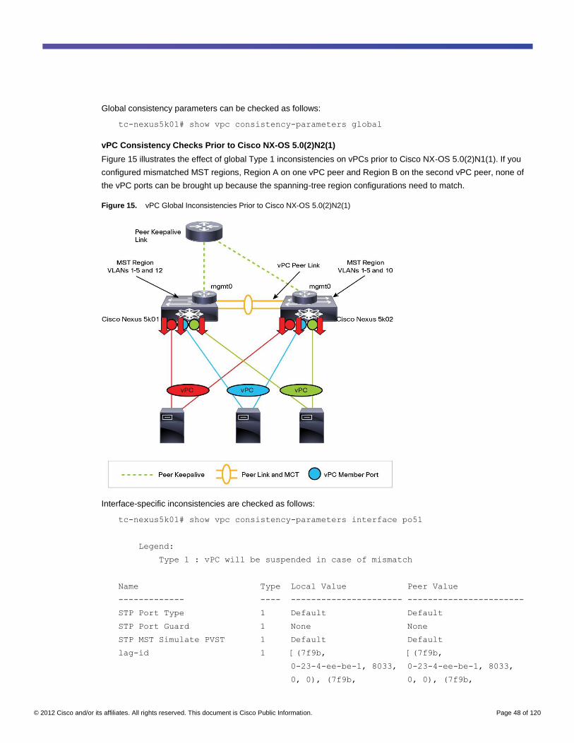
© 2012 Cisco and/or its affiliates. All rights reserved. This document is Cisco Public Information. Page 48 of 120
Global consistency parameters can be checked as follows:
tc-nexus5k01# show vpc consistency-parameters global
vPC Consistency Checks Prior to Cisco NX-OS 5.0(2)N2(1)
Figure 15 illustrates the effect of global Type 1 inconsistencies on vPCs prior to Cisco NX-OS 5.0(2)N1(1). If you
configured mismatched MST regions, Region A on one vPC peer and Region B on the second vPC peer, none of
the vPC ports can be brought up because the spanning-tree region configurations need to match.
Figure 15. vPC Global Inconsistencies Prior to Cisco NX-OS 5.0(2)N2(1)
Interface-specific inconsistencies are checked as follows:
tc-nexus5k01# show vpc consistency-parameters interface po51
Legend:
Type 1 : vPC will be suspended in case of mismatch
Name Type Local Value Peer Value
------------- ---- ---------------------- -----------------------
STP Port Type 1 Default Default
STP Port Guard 1 None None
STP MST Simulate PVST 1 Default Default
lag-id 1 [(7f9b, [(7f9b,
0-23-4-ee-be-1, 8033, 0-23-4-ee-be-1, 8033,
0, 0), (7f9b, 0, 0), (7f9b,
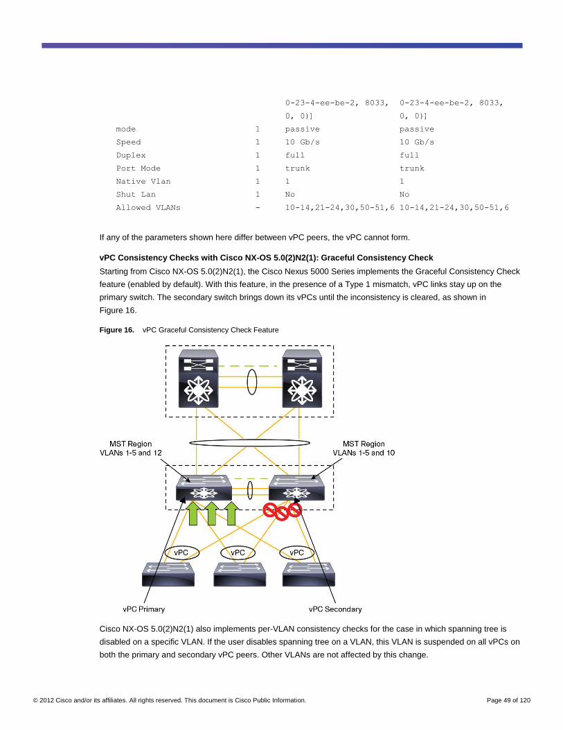
© 2012 Cisco and/or its affiliates. All rights reserved. This document is Cisco Public Information. Page 49 of 120
0-23-4-ee-be-2, 8033, 0-23-4-ee-be-2, 8033,
0, 0)] 0, 0)]
mode 1 passive passive
Speed 1 10 Gb/s 10 Gb/s
Duplex 1 full full
Port Mode 1 trunk trunk
Native Vlan 1 1 1
Shut Lan 1 No No
Allowed VLANs - 10-14,21-24,30,50-51,6 10-14,21-24,30,50-51,6
If any of the parameters shown here differ between vPC peers, the vPC cannot form.
vPC Consistency Checks with Cisco NX-OS 5.0(2)N2(1): Graceful Consistency Check
Starting from Cisco NX-OS 5.0(2)N2(1), the Cisco Nexus 5000 Series implements the Graceful Consistency Check
feature (enabled by default). With this feature, in the presence of a Type 1 mismatch, vPC links stay up on the
primary switch. The secondary switch brings down its vPCs until the inconsistency is cleared, as shown in
Figure 16.
Figure 16. vPC Graceful Consistency Check Feature
Cisco NX-OS 5.0(2)N2(1) also implements per-VLAN consistency checks for the case in which spanning tree is
disabled on a specific VLAN. If the user disables spanning tree on a VLAN, this VLAN is suspended on all vPCs on
both the primary and secondary vPC peers. Other VLANs are not affected by this change.
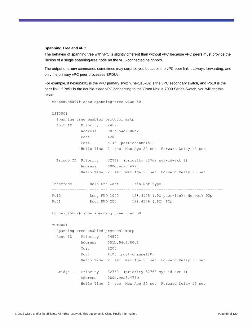
© 2012 Cisco and/or its affiliates. All rights reserved. This document is Cisco Public Information. Page 50 of 120
Spanning Tree and vPC
The behavior of spanning tree with vPC is slightly different than without vPC because vPC peers must provide the
illusion of a single spanning-tree node on the vPC-connected neighbors.
The output of show commands sometimes may surprise you because the vPC peer link is always forwarding, and
only the primary vPC peer processes BPDUs.
For example, if nexus5k01 is the vPC primary switch, nexus5k02 is the vPC secondary switch, and Po10 is the
peer link, if Po51 is the double-sided vPC connecting to the Cisco Nexus 7000 Series Switch, you will get this
result:
tc-nexus5k01# show spanning-tree vlan 50
MST0001
Spanning tree enabled protocol mstp
Root ID Priority 24577
Address 001b.54c2.80c2
Cost 1200
Port 4146 (port-channel51)
Hello Time 2 sec Max Age 20 sec Forward Delay 15 sec
Bridge ID Priority 32769 (priority 32768 sys-id-ext 1)
Address 000d.eca3.477c
Hello Time 2 sec Max Age 20 sec Forward Delay 15 sec
Interface Role Sts Cost Prio.Nbr Type
---------------- ---- --- --------- -------- --------------------------------
Po10 Desg FWD 1000 128.4105 (vPC peer-link) Network P2p
Po51 Root FWD 200 128.4146 (vPC) P2p
tc-nexus5k02# show spanning-tree vlan 50
MST0001
Spanning tree enabled protocol mstp
Root ID Priority 24577
Address 001b.54c2.80c2
Cost 2200
Port 4105 (port-channel10)
Hello Time 2 sec Max Age 20 sec Forward Delay 15 sec
Bridge ID Priority 32769 (priority 32768 sys-id-ext 1)
Address 000d.eca3.47fc
Hello Time 2 sec Max Age 20 sec Forward Delay 15 sec
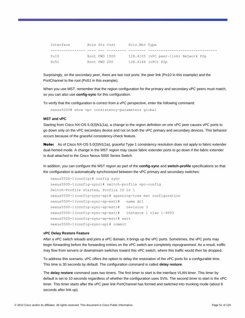
© 2012 Cisco and/or its affiliates. All rights reserved. This document is Cisco Public Information. Page 51 of 120
Interface Role Sts Cost Prio.Nbr Type
---------------- ---- --- --------- -------- --------------------------------
Po10 Root FWD 1000 128.4105 (vPC peer-link) Network P2p
Po51 Root FWD 200 128.4146 (vPC) P2p
Surprisingly, on the secondary peer, there are two root ports: the peer link (Po10 in this example) and the
PortChannel to the root (Po51 in this example).
When you use MST, remember that the region configuration for the primary and secondary vPC peers must match,
so you can also use config-sync for this configuration.
To verify that the configuration is correct from a vPC perspective, enter the following command:
nexus5000# show vpc consistency-parameters global
MST and vPC
Starting from Cisco NX-OS 5.0(3)N1(1a), a change to the region definition on one vPC peer causes vPC ports to
go down only on the vPC secondary device and not on both the vPC primary and secondary devices. This behavior
occurs because of the graceful consistency-check feature.
Note: As of Cisco NX-OS 5.0(3)N1(1a), graceful Type 1 consistency resolution does not apply to fabric extender
dual-homed mode. A change in the MST region may cause fabric extender ports to go down if the fabric extender
is dual-attached to the Cisco Nexus 5000 Series Switch.
In addition, you can configure the MST region as part of the config-sync and switch-profile specifications so that
the configuration is automatically synchronized between the vPC primary and secondary switches:
nexus5500-1(config)# config sync
nexus5500-1(config-sync)# switch-profile vpc-config
Switch-Profile started, Profile ID is 1
nexus5500-1(config-sync-sp)# spanning-tree mst configuration
nexus5500-1(config-sync-sp-mst)# name dc1
nexus5500-1(config-sync-sp-mst)# revision 3
nexus5500-1(config-sync-sp-mst)# instance 1 vlan 1-4093
nexus5500-1(config-sync-sp-mst)# exit
nexus5500-1(config-sync-sp)# commit
vPC Delay Restore Feature
After a vPC switch reloads and joins a vPC domain, it brings up the vPC ports. Sometimes, the vPC ports may
begin forwarding before the forwarding entries on the vPC switch are completely reprogrammed. As a result, traffic
may flow from servers or downstream switches toward this vPC switch, where this traffic would then be dropped.
To address this scenario, vPC offers the option to delay the restoration of the vPC ports for a configurable time.
This time is 30 seconds by default. The configuration command is called delay restore.
The delay restore command uses two timers. The first timer to start is the interface VLAN timer. This timer by
default is set to 10 seconds regardless of whether the configuration uses SVIs. The second timer to start is the vPC
timer. This timer starts after the vPC peer link PortChannel has formed and switched into trunking mode (about 8
seconds after link up).
© 2012 Cisco and/or its affiliates. All rights reserved. This document is Cisco Public Information. Page 52 of 120
nexus5500-1(config-vpc-domain)# delay restore ?
<1-3600> Delay in bringing up the vPC links (in seconds)
interface-vlan Delay in bringing-up interface-vlan
If there are no SVIs configured because you are using the Cisco Nexus 5000 Series in Layer 2 mode, you may
want to lower the delay restore interface VLAN timer value to 1 second.
Multicast Traffic
Under normal conditions, the peer link does not carry a significant amount of traffic because unicast traffic enters
and exits the Cisco Nexus 5000 Series Switch from one of the vPC member ports. Other traffic types use the peer
link:
● Traffic destined for orphan ports
● Multicast traffic and broadcast traffic
Figure 17 shows how multicast works with vPC. When a server joins a multicast group, it sends an IGMP report,
which is synchronized between the vPC peers (N5k01 and N5k02). This synchronization is performed to associate
the multicast MAC addresses of that given multicast group with the vPC member port on the peer Cisco Nexus
5000 Series Switch.
Note: Prior to Cisco NX-OS 5.0(3)N1(1a), when a vPC switch was reloaded, or when the peer link flapped,
IGMP entries that had been learned by a vPC peer would not be automatically synchronized with the other peer,
resulting in slower convergence times. Starting from Cisco NX-OS 5.0(3)N1(1a), the restoration of the peer link
triggers a bulk synchronization of the IGMP entries from one vPC peer to the other, to reduce traffic loss.
When a multicast stream arrives from the aggregation layer, it can be hashed to either Cisco Nexus 5000 Series
Switch (N5k01 or N5k02; in Figure 17, it is N5k02). Both vPC peers have the multicast entry already associated
with the receiver (server 1 in the figure). This multicast stream not only is sent to the receiver but also over the vPC
peer link, in case there are other single-attached subscribers on N5k01. Server 1 on N5k01 does not receive a
duplicate copy because the vPC duplicate prevention mechanism intervenes and prevents the frames from
reaching vPC member ports.
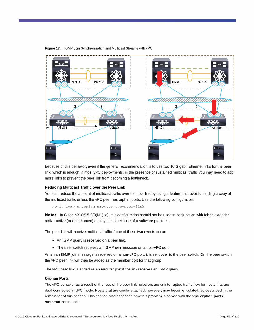
© 2012 Cisco and/or its affiliates. All rights reserved. This document is Cisco Public Information. Page 53 of 120
Figure 17. IGMP Join Synchronization and Multicast Streams with vPC
Because of this behavior, even if the general recommendation is to use two 10 Gigabit Ethernet links for the peer
link, which is enough in most vPC deployments, in the presence of sustained multicast traffic you may need to add
more links to prevent the peer link from becoming a bottleneck.
Reducing Multicast Traffic over the Peer Link
You can reduce the amount of multicast traffic over the peer link by using a feature that avoids sending a copy of
the multicast traffic unless the vPC peer has orphan ports. Use the following configuration:
no ip igmp snooping mrouter vpc-peer-link
Note: In Cisco NX-OS 5.0(3)N1(1a), this configuration should not be used in conjunction with fabric extender
active-active (or dual-homed) deployments because of a software problem.
The peer link will receive multicast traffic if one of these two events occurs:
● An IGMP query is received on a peer link.
● The peer switch receives an IGMP join message on a non-vPC port.
When an IGMP join message is received on a non-vPC port, it is sent over to the peer switch. On the peer switch
the vPC peer link will then be added as the member port for that group.
The vPC peer link is added as an mrouter port if the link receives an IGMP query.
Orphan Ports
The vPC behavior as a result of the loss of the peer link helps ensure uninterrupted traffic flow for hosts that are
dual-connected in vPC mode. Hosts that are single-attached, however, may become isolated, as described in the
remainder of this section. This section also describes how this problem is solved with the vpc orphan ports
suspend command.
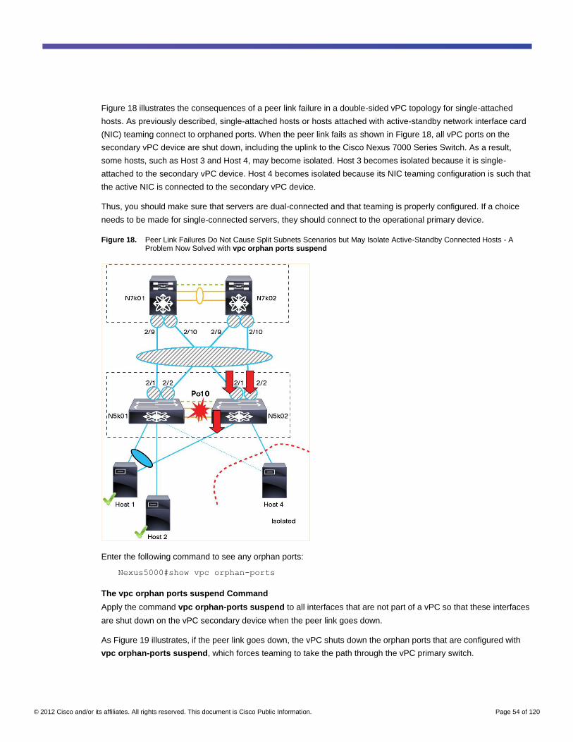
© 2012 Cisco and/or its affiliates. All rights reserved. This document is Cisco Public Information. Page 54 of 120
Figure 18 illustrates the consequences of a peer link failure in a double-sided vPC topology for single-attached
hosts. As previously described, single-attached hosts or hosts attached with active-standby network interface card
(NIC) teaming connect to orphaned ports. When the peer link fails as shown in Figure 18, all vPC ports on the
secondary vPC device are shut down, including the uplink to the Cisco Nexus 7000 Series Switch. As a result,
some hosts, such as Host 3 and Host 4, may become isolated. Host 3 becomes isolated because it is single-
attached to the secondary vPC device. Host 4 becomes isolated because its NIC teaming configuration is such that
the active NIC is connected to the secondary vPC device.
Thus, you should make sure that servers are dual-connected and that teaming is properly configured. If a choice
needs to be made for single-connected servers, they should connect to the operational primary device.
Figure 18. Peer Link Failures Do Not Cause Split Subnets Scenarios but May Isolate Active-Standby Connected Hosts - A Problem Now Solved with vpc orphan ports suspend
Enter the following command to see any orphan ports:
Nexus5000#show vpc orphan-ports
The vpc orphan ports suspend Command
Apply the command vpc orphan-ports suspend to all interfaces that are not part of a vPC so that these interfaces
are shut down on the vPC secondary device when the peer link goes down.
As Figure 19 illustrates, if the peer link goes down, the vPC shuts down the orphan ports that are configured with
vpc orphan-ports suspend, which forces teaming to take the path through the vPC primary switch.
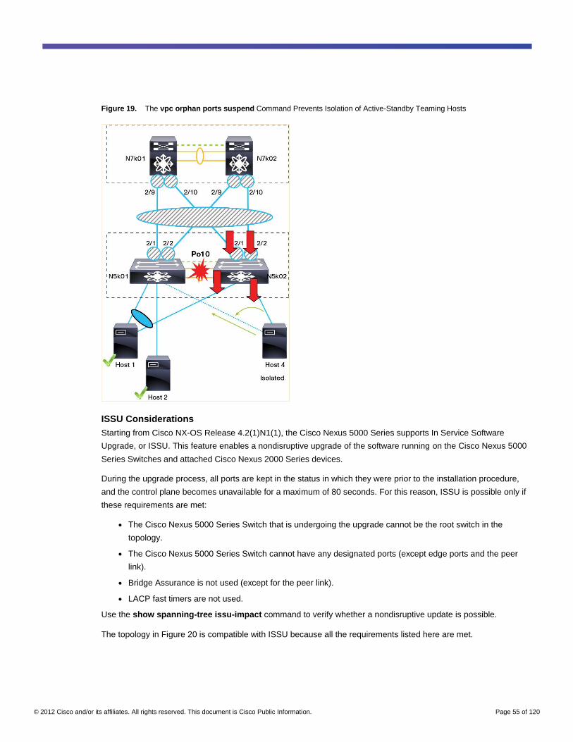
© 2012 Cisco and/or its affiliates. All rights reserved. This document is Cisco Public Information. Page 55 of 120
Figure 19. The vpc orphan ports suspend Command Prevents Isolation of Active-Standby Teaming Hosts
ISSU Considerations
Starting from Cisco NX-OS Release 4.2(1)N1(1), the Cisco Nexus 5000 Series supports In Service Software
Upgrade, or ISSU. This feature enables a nondisruptive upgrade of the software running on the Cisco Nexus 5000
Series Switches and attached Cisco Nexus 2000 Series devices.
During the upgrade process, all ports are kept in the status in which they were prior to the installation procedure,
and the control plane becomes unavailable for a maximum of 80 seconds. For this reason, ISSU is possible only if
these requirements are met:
● The Cisco Nexus 5000 Series Switch that is undergoing the upgrade cannot be the root switch in the
topology.
● The Cisco Nexus 5000 Series Switch cannot have any designated ports (except edge ports and the peer
link).
● Bridge Assurance is not used (except for the peer link).
● LACP fast timers are not used.
Use the show spanning-tree issu-impact command to verify whether a nondisruptive update is possible.
The topology in Figure 20 is compatible with ISSU because all the requirements listed here are met.
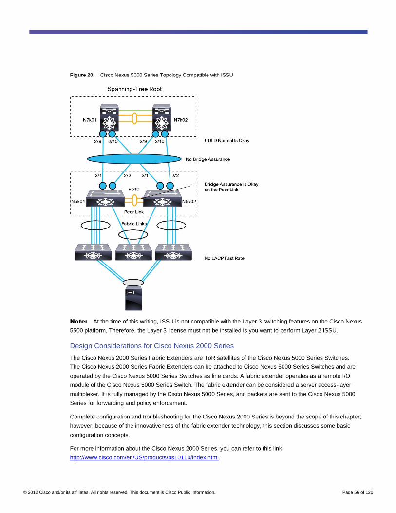
© 2012 Cisco and/or its affiliates. All rights reserved. This document is Cisco Public Information. Page 56 of 120
Figure 20. Cisco Nexus 5000 Series Topology Compatible with ISSU
Note: At the time of this writing, ISSU is not compatible with the Layer 3 switching features on the Cisco Nexus
5500 platform. Therefore, the Layer 3 license must not be installed is you want to perform Layer 2 ISSU.
Design Considerations for Cisco Nexus 2000 Series
The Cisco Nexus 2000 Series Fabric Extenders are ToR satellites of the Cisco Nexus 5000 Series Switches.
The Cisco Nexus 2000 Series Fabric Extenders can be attached to Cisco Nexus 5000 Series Switches and are
operated by the Cisco Nexus 5000 Series Switches as line cards. A fabric extender operates as a remote I/O
module of the Cisco Nexus 5000 Series Switch. The fabric extender can be considered a server access-layer
multiplexer. It is fully managed by the Cisco Nexus 5000 Series, and packets are sent to the Cisco Nexus 5000
Series for forwarding and policy enforcement.
Complete configuration and troubleshooting for the Cisco Nexus 2000 Series is beyond the scope of this chapter;
however, because of the innovativeness of the fabric extender technology, this section discusses some basic
configuration concepts.
For more information about the Cisco Nexus 2000 Series, you can refer to this link:
http://www.cisco.com/en/US/products/ps10110/index.html.
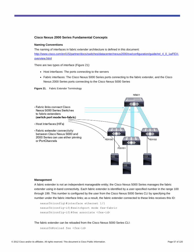
© 2012 Cisco and/or its affiliates. All rights reserved. This document is Cisco Public Information. Page 57 of 120
Cisco Nexus 2000 Series Fundamental Concepts
Naming Conventions
The naming of interfaces in fabric extender architecture is defined in this document:
http://www.cisco.com/en/US/partner/docs/switches/datacenter/nexus2000/sw/configuration/guide/rel_4_0_1a/FEX-
overview.html
There are two types of interface (Figure 21):
● Host interfaces: The ports connecting to the servers
● Fabric interfaces: The Cisco Nexus 5000 Series ports connecting to the fabric extender, and the Cisco
Nexus 2000 Series ports connecting to the Cisco Nexus 5000 Series
Figure 21. Fabric Extender Terminology
Management
A fabric extender is not an independent manageable entity; the Cisco Nexus 5000 Series manages the fabric
extender using in-band connectivity. Each fabric extender is identified by a user-specified number in the range 100
through 199. This number is configured by the user from the Cisco Nexus 5000 Series CLI by specifying the
number under the fabric interface links; as a result, the fabric extender connected to these links receives this ID:
nexus5k(config)#interface ethernet 1/1
nexus5k(config-if)#switchport mode fex-fabric
nexus5k(config-if)#fex associate <fex-id>
The fabric extender can be reloaded from the Cisco Nexus 5000 Series CLI:
nexus5k#reload fex <fex-id>
© 2012 Cisco and/or its affiliates. All rights reserved. This document is Cisco Public Information. Page 58 of 120
Useful commands include the following:
nexus5k# show inventory fex <fex-id>
nexus5k# show logging onboard fex <fex-id>
nexus5k# show environment fex <fex-id>
Software Installation
A bootloader resides on the fabric extender device and is write protected. The fabric extender contains two copies
of the system image: the primary system image, which is stored in flash memory and can be upgraded only by the
Cisco Nexus 5000 Series Switch, and a backup system image stored in bootflash memory and write protected.
This backup image is used only if the primary image is corrupted. When a fabric extender is connected to a Cisco
Nexus 5000 Series Switch, a handshake verifies the image version on the fabric extender, and the switch
determines whether the fabric extender needs to be updated. If an upgrade is necessary, the Cisco Nexus 5000
Series Switch loads the code onto the fabric extender and reboots the fabric extender with the new image. The
update takes approximately 8 minutes.
The installation procedure does not differ from the regular Cisco Nexus 5000 Series upgrade procedure. While the
Cisco Nexus 5000 Series is being upgraded, the fabric extender is still online.
The version of the code running on the fabric extender can be retrieved with this command:
nexus5k#show version fex <fex-id>
Alternatively, you can connect to the fabric extender and then enter a show version command:
nexus5k#attach fex <fex-id>
fex-id#show version
You can observe the effect of an install all command by entering this command without performing the installation:
nexus5k#show install all impact kickstart <path> system <path>
Cisco Nexus 2000 Series Preprovisioning
The fabric extender preprovisioning feature was introduced in Cisco NX-OS 5.0(2)N1(1). To understand
preprovisioning, you first must be familiar with the way fabric extender modules are programmed by the Cisco
Nexus 5000 Series.
The first part of the configuration in the Cisco Nexus 5000 Series is used to assign the fabric extender a number,
the fabric extender ID (fex-id). After the fabric extender is discovered, the Cisco Nexus 5000 Series Switch can
program its interfaces.
The configuration shown here triggers the discovery of the fabric extender and the correct programming of the
fabric extender:
interface Ethernet <a/b>
switchport mode fex-fabric
fex associate 198
After the fabric extender is recognized and programmed, you can configure fabric extender ports with commands
such as interface ethernet198/1/1, interface ethernet198/1/2, etc.
© 2012 Cisco and/or its affiliates. All rights reserved. This document is Cisco Public Information. Page 59 of 120
Under certain conditions, you may want to apply the interface configurations before the fabric extender has been
fully discovered or before the fabric extender has been attached to the Cisco Nexus 5000 Series Switch. To do so,
you can use the preprovisioning feature:
slot 198
provision model N2K-C2232P
With the preceding configuration in place, you can configure the ports on the fabric extender even before the fabric
extender is connected to the Cisco Nexus 5000 Series Switch.
Number of Fabric Extenders per Cisco Nexus 5000 Series Switch
The number of fabric extenders that can be attached to a Cisco Nexus 5000 Series Switch varies with the Cisco
Nexus 5000 Series model and with the software release.
With the Cisco Nexus 5500 platform, the number of fabric extenders supported is as follows:
● Cisco NX-OS 5.0(3)N1(1a) supports up to 24 fabric extenders for each Cisco Nexus 5500 platform switch,
and up to 8 fabric extenders for each Cisco Nexus 5500 platform switch if the Layer license is used.
● Cisco NX-OS 5.0(2)N1(1) supports up to 16 fabric extenders for each Cisco Nexus 5500 platform switch
(Layer 3 functions cannot be used with this software release).
With the other Cisco Nexus 5000 Series Switches, the number of fabric extenders supported is as follows:
● Starting from Cisco NX-OS 4.2(1)N1(1), the Cisco Nexus 5020 and 501 support up to 12 fabric extenders.
Connectivity Between Cisco Nexus 2000 and 5000 Series
Cisco Nexus 2000 Series Fabric Extenders are not independently manageable entities; the Cisco Nexus 5000
Series Switch manages the fabric extenders through in-band connectivity. The Cisco Nexus 2000 Series can be
attached to the Cisco Nexus 5000 Series in two configurations:
● Static pinning: The front host ports on the module are divided across the fabric ports (that is, the uplinks
connecting to the Cisco Nexus 5000 Series Switch).
● PortChannel: The fabric ports form a PortChannel to the Cisco Nexus 5000 Series Switch.
The main advantage of static pinning over a PortChannel is that there is little chance for oversubscription (as long
as all four uplinks are used). With a PortChannel, many flows may end up hashing to the same uplink, thus causing
flow control to occur on more ports than just the ports responsible for the congestion.
However, static pinning does not offer automatic reassignment of the host ports to the remaining uplinks when an
uplink fails. Behavior is similar to uplink tracking on other Cisco platforms, in which uplink failure is tracked and
shuts down the associated host ports.
Static Pinning
The ports connecting the Cisco Nexus 5000 Series Switch to a Cisco Nexus 2000 Series Fabric Extender are
referred to as fabric ports. The ports to which servers connect are referred to as host ports.
Simply connecting fabric ports between the Cisco Nexus 5000 Series Switch and Cisco Nexus 2000 Series Fabric
Extender is not enough for the two devices to start forwarding traffic. All host interfaces on the fabric extender are
assigned to one of the uplinks. The command pinning max-links defines the way the ports are divided across the
uplinks.
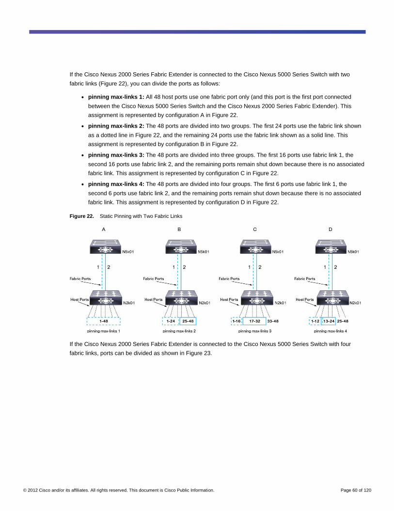
© 2012 Cisco and/or its affiliates. All rights reserved. This document is Cisco Public Information. Page 60 of 120
If the Cisco Nexus 2000 Series Fabric Extender is connected to the Cisco Nexus 5000 Series Switch with two
fabric links (Figure 22), you can divide the ports as follows:
● pinning max-links 1: All 48 host ports use one fabric port only (and this port is the first port connected
between the Cisco Nexus 5000 Series Switch and the Cisco Nexus 2000 Series Fabric Extender). This
assignment is represented by configuration A in Figure 22.
● pinning max-links 2: The 48 ports are divided into two groups. The first 24 ports use the fabric link shown
as a dotted line in Figure 22, and the remaining 24 ports use the fabric link shown as a solid line. This
assignment is represented by configuration B in Figure 22.
● pinning max-links 3: The 48 ports are divided into three groups. The first 16 ports use fabric link 1, the
second 16 ports use fabric link 2, and the remaining ports remain shut down because there is no associated
fabric link. This assignment is represented by configuration C in Figure 22.
● pinning max-links 4: The 48 ports are divided into four groups. The first 6 ports use fabric link 1, the
second 6 ports use fabric link 2, and the remaining ports remain shut down because there is no associated
fabric link. This assignment is represented by configuration D in Figure 22.
Figure 22. Static Pinning with Two Fabric Links
If the Cisco Nexus 2000 Series Fabric Extender is connected to the Cisco Nexus 5000 Series Switch with four
fabric links, ports can be divided as shown in Figure 23.
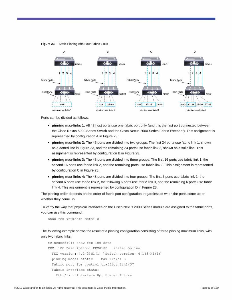
© 2012 Cisco and/or its affiliates. All rights reserved. This document is Cisco Public Information. Page 61 of 120
Figure 23. Static Pinning with Four Fabric Links
Ports can be divided as follows:
● pinning max-links 1: All 48 host ports use one fabric port only (and this the first port connected between
the Cisco Nexus 5000 Series Switch and the Cisco Nexus 2000 Series Fabric Extender). This assignment is
represented by configuration A in Figure 23.
● pinning max-links 2: The 48 ports are divided into two groups. The first 24 ports use fabric link 1, shown
as a dotted line in Figure 23, and the remaining 24 ports use fabric link 2, shown as a solid line. This
assignment is represented by configuration B in Figure 23.
● pinning max-links 3: The 48 ports are divided into three groups. The first 16 ports use fabric link 1, the
second 16 ports use fabric link 2, and the remaining ports use fabric link 3. This assignment is represented
by configuration C in Figure 23.
● pinning max-links 4: The 48 ports are divided into four groups. The first 6 ports use fabric link 1, the
second 6 ports use fabric link 2, the following 6 ports use fabric link 3, and the remaining 6 ports use fabric
link 4. This assignment is represented by configuration D in Figure 23.
The pinning order depends on the order of fabric port configuration, regardless of when the ports come up or
whether they come up.
To verify the way that physical interfaces on the Cisco Nexus 2000 Series module are assigned to the fabric ports,
you can use this command:
show fex <number> details
The following example shows the result of a pinning configuration consisting of three pinning maximum links, with
only two fabric links:
tc-nexus5k01# show fex 100 deta
FEX: 100 Description: FEX0100 state: Online
FEX version: 4.1(3)N1(1) [Switch version: 4.1(3)N1(1)]
pinning-mode: static Max-links: 3
Fabric port for control traffic: Eth1/37
Fabric interface state:
Eth1/37 - Interface Up. State: Active
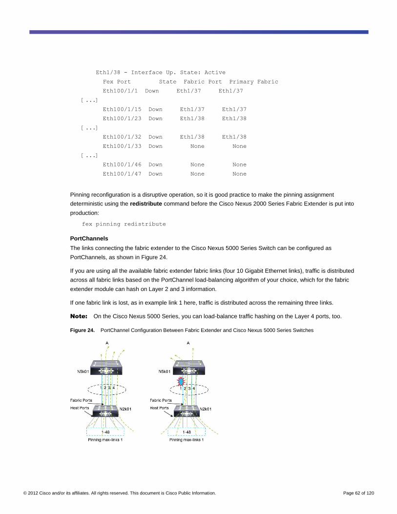
© 2012 Cisco and/or its affiliates. All rights reserved. This document is Cisco Public Information. Page 62 of 120
Eth1/38 - Interface Up. State: Active
Fex Port State Fabric Port Primary Fabric
Eth100/1/1 Down Eth1/37 Eth1/37
[...]
Eth100/1/15 Down Eth1/37 Eth1/37
Eth100/1/23 Down Eth1/38 Eth1/38
[...]
Eth100/1/32 Down Eth1/38 Eth1/38
Eth100/1/33 Down None None
[...]
Eth100/1/46 Down None None
Eth100/1/47 Down None None
Pinning reconfiguration is a disruptive operation, so it is good practice to make the pinning assignment
deterministic using the redistribute command before the Cisco Nexus 2000 Series Fabric Extender is put into
production:
fex pinning redistribute
PortChannels
The links connecting the fabric extender to the Cisco Nexus 5000 Series Switch can be configured as
PortChannels, as shown in Figure 24.
If you are using all the available fabric extender fabric links (four 10 Gigabit Ethernet links), traffic is distributed
across all fabric links based on the PortChannel load-balancing algorithm of your choice, which for the fabric
extender module can hash on Layer 2 and 3 information.
If one fabric link is lost, as in example link 1 here, traffic is distributed across the remaining three links.
Note: On the Cisco Nexus 5000 Series, you can load-balance traffic hashing on the Layer 4 ports, too.
Figure 24. PortChannel Configuration Between Fabric Extender and Cisco Nexus 5000 Series Switches
© 2012 Cisco and/or its affiliates. All rights reserved. This document is Cisco Public Information. Page 63 of 120
Static Pinning Compared to PortChannels
To understand the difference between static pinning and PortChannels, you need to understand the architectural
foundation of the fabric extender concept:
● A fabric extender is in some ways similar to a line card connected to a central supervisor (the Cisco Nexus
5000 Series Switch).
● A fabric extender does not perform any local switching; all switching happens on the supervisor.
● If congestion occurs (as a result of an oversubscribed fabric extender deployment), the congestion is
pushed to the edge ports.
With static pinning, you have more control over which server ports are affected by congestion. With PortChannels,
you cannot control to which uplink the traffic is hashed, so it is hard to predict which host ports will be affected by
congestion.
With four 10 Gigabit Ethernet uplinks, on the 48-port fabric extender oversubscription is limited to 1.2:1 which
makes congestion an unlikely occurrence. Even with higher oversubscription ratios, congestion should be
evaluated case by case, because data centers today run with varying levels of oversubscription, and for example,
10:1 or even higher oversubscription is not uncommon.
Using static pinning requires proper NIC teaming configuration on the server side to accommodate the loss of one
of the fabric links. With PortChannels, the loss of a single fabric link does not require server teaming intervention.
The rest of this chapter focuses on designs based on PortChannels and not on static pinning.
Distance Between Cisco Nexus 2000 Series Fabric Extender and 5000 Series Switch
With Cisco NX-OS 5.0(2)N1(1) and later, the maximum distance between the fabric extender and the Cisco Nexus
5000 Series Switch has been increased to 3 km (from 300m). For more information, see the following link:
http://www.cisco.com/en/US/docs/switches/datacenter/nexus5000/sw/release/notes/Rel_5_0_2_N1_1/Nexus5000_
Release_Notes_5_0_2_N1_1.html#wp240540
Depending on the optics that are used for connectivity, the distances between the fabric extender and the Cisco
Nexus 5000 Series Switch can now be as follows:
● SFP-10G-LR: Up to 3 km (single-mode fiber [SMF])
● SFP-10G-SR: Up to 300m (OM3; 2000 MHz *km MBW at 850 nm)
● FET-10G: Up to 100m (OM3; 2000 MHz * km MBWat 850 nm)
Note: When the Cisco Nexus 2232PP is used to carry FCoE traffic too, the maximum distance between the
Cisco Nexus 2232PP and the Cisco Nexus 5000 Series Switch is 300m.
You can change the distance configuration for a given fabric extender using the following command (this example
extends the distance between the Cisco Nexus 2248TP-E and the Cisco Nexus 5000 Series Switch to 2.5 km):
switch(config-fex)# hardware N2248TP-E uplink-pause-no-drop distance 2500
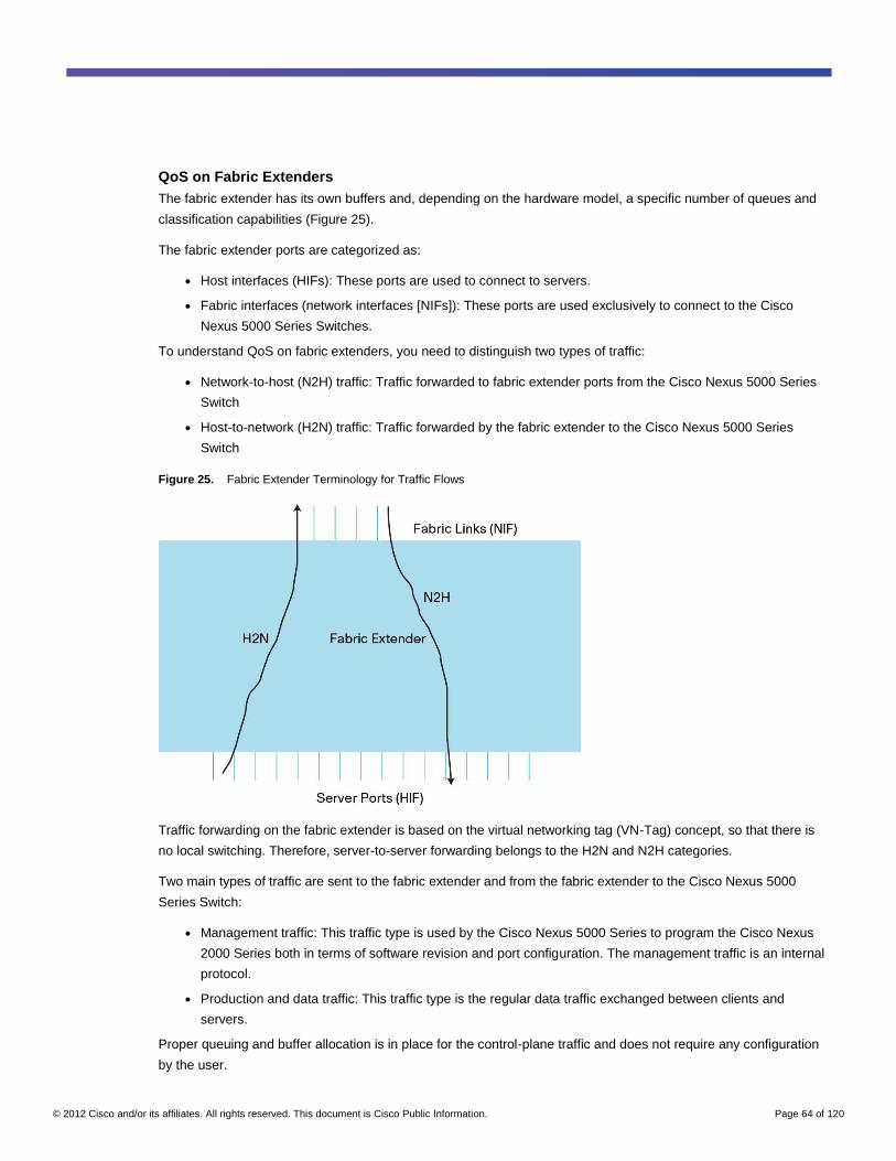
© 2012 Cisco and/or its affiliates. All rights reserved. This document is Cisco Public Information. Page 64 of 120
QoS on Fabric Extenders
The fabric extender has its own buffers and, depending on the hardware model, a specific number of queues and
classification capabilities (Figure 25).
The fabric extender ports are categorized as:
● Host interfaces (HIFs): These ports are used to connect to servers.
● Fabric interfaces (network interfaces [NIFs]): These ports are used exclusively to connect to the Cisco
Nexus 5000 Series Switches.
To understand QoS on fabric extenders, you need to distinguish two types of traffic:
● Network-to-host (N2H) traffic: Traffic forwarded to fabric extender ports from the Cisco Nexus 5000 Series
Switch
● Host-to-network (H2N) traffic: Traffic forwarded by the fabric extender to the Cisco Nexus 5000 Series
Switch
Figure 25. Fabric Extender Terminology for Traffic Flows
Traffic forwarding on the fabric extender is based on the virtual networking tag (VN-Tag) concept, so that there is
no local switching. Therefore, server-to-server forwarding belongs to the H2N and N2H categories.
Two main types of traffic are sent to the fabric extender and from the fabric extender to the Cisco Nexus 5000
Series Switch:
● Management traffic: This traffic type is used by the Cisco Nexus 5000 Series to program the Cisco Nexus
2000 Series both in terms of software revision and port configuration. The management traffic is an internal
protocol.
● Production and data traffic: This traffic type is the regular data traffic exchanged between clients and
servers.
Proper queuing and buffer allocation is in place for the control-plane traffic and does not require any configuration
by the user.
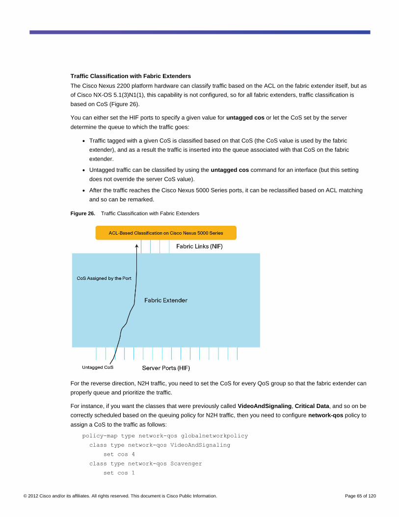
© 2012 Cisco and/or its affiliates. All rights reserved. This document is Cisco Public Information. Page 65 of 120
Traffic Classification with Fabric Extenders
The Cisco Nexus 2200 platform hardware can classify traffic based on the ACL on the fabric extender itself, but as
of Cisco NX-OS 5.1(3)N1(1), this capability is not configured, so for all fabric extenders, traffic classification is
based on CoS (Figure 26).
You can either set the HIF ports to specify a given value for untagged cos or let the CoS set by the server
determine the queue to which the traffic goes:
● Traffic tagged with a given CoS is classified based on that CoS (the CoS value is used by the fabric
extender), and as a result the traffic is inserted into the queue associated with that CoS on the fabric
extender.
● Untagged traffic can be classified by using the untagged cos command for an interface (but this setting
does not override the server CoS value).
● After the traffic reaches the Cisco Nexus 5000 Series ports, it can be reclassified based on ACL matching
and so can be remarked.
Figure 26. Traffic Classification with Fabric Extenders
For the reverse direction, N2H traffic, you need to set the CoS for every QoS group so that the fabric extender can
properly queue and prioritize the traffic.
For instance, if you want the classes that were previously called VideoAndSignaling, Critical Data, and so on be
correctly scheduled based on the queuing policy for N2H traffic, then you need to configure network-qos policy to
assign a CoS to the traffic as follows:
policy-map type network-qos globalnetworkpolicy
class type network-qos VideoAndSignaling
set cos 4
class type network-qos Scavenger
set cos 1
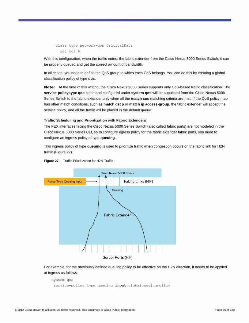
© 2012 Cisco and/or its affiliates. All rights reserved. This document is Cisco Public Information. Page 66 of 120
class type network-qos CriticalData
set cos 6
With this configuration, when the traffic enters the fabric extender from the Cisco Nexus 5000 Series Switch, it can
be properly queued and get the correct amount of bandwidth.
In all cases, you need to define the QoS group to which each CoS belongs. You can do this by creating a global
classification policy of type qos.
Note: At the time of this writing, the Cisco Nexus 2000 Series supports only CoS-based traffic classification. The
service-policy type qos command configured under system qos will be populated from the Cisco Nexus 5000
Series Switch to the fabric extender only when all the match cos matching criteria are met. If the QoS policy map
has other match conditions, such as match dscp or match ip access-group, the fabric extender will accept the
service policy, and all the traffic will be placed in the default queue.
Traffic Scheduling and Prioritization with Fabric Extenders
The FEX interfaces facing the Cisco Nexus 5000 Series Switch (also called fabric ports) are not modeled in the
Cisco Nexus 5000 Series CLI, so to configure egress policy for the fabric extender fabric ports, you need to
configure an ingress policy of type queuing.
This ingress policy of type queuing is used to prioritize traffic when congestion occurs on the fabric link for H2N
traffic (Figure 27).
Figure 27. Traffic Prioritization for H2N Traffic
For example, for the previously defined queuing policy to be effective on the H2N direction, it needs to be applied
at ingress as follows:
system qos
service-policy type queuing input globalqueuingpolicy
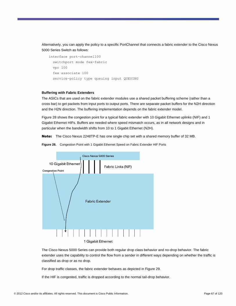
© 2012 Cisco and/or its affiliates. All rights reserved. This document is Cisco Public Information. Page 67 of 120
Alternatively, you can apply the policy to a specific PortChannel that connects a fabric extender to the Cisco Nexus
5000 Series Switch as follows:
interface port-channel100
switchport mode fex-fabric
vpc 100
fex associate 100
service-policy type queuing input QUEUING
Buffering with Fabric Extenders
The ASICs that are used on the fabric extender modules use a shared packet buffering scheme (rather than a
cross bar) to get packets from input ports to output ports. There are separate packet buffers for the N2H direction
and the H2N direction. The buffering implementation depends on the fabric extender model.
Figure 28 shows the congestion point for a typical fabric extender with 10 Gigabit Ethernet uplinks (NIF) and 1
Gigabit Ethernet HIFs. Buffers are needed where speed mismatch occurs, as in all network designs and in
particular when the bandwidth shifts from 10 to 1 Gigabit Ethernet (N2H).
Note: The Cisco Nexus 2248TP-E has one single chip set with a shared memory buffer of 32 MB.
Figure 28. Congestion Point with 1 Gigabit Ethernet Speed on Fabric Extender HIF Ports
The Cisco Nexus 5000 Series can provide both regular drop class behavior and no-drop behavior. The fabric
extender uses the capability to control the flow from a sender in different ways depending on whether the traffic is
classified as drop or as no drop.
For drop traffic classes, the fabric extender behaves as depicted in Figure 29.
If the HIF is congested, traffic is dropped according to the normal tail-drop behavior.
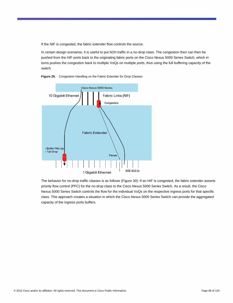
© 2012 Cisco and/or its affiliates. All rights reserved. This document is Cisco Public Information. Page 68 of 120
If the NIF is congested, the fabric extender flow controls the source.
In certain design scenarios, it is useful to put N2H traffic in a no-drop class. The congestion then can then be
pushed from the HIF ports back to the originating fabric ports on the Cisco Nexus 5000 Series Switch, which in
turns pushes the congestion back to multiple VoQs on multiple ports, thus using the full buffering capacity of the
switch.
Figure 29. Congestion Handling on the Fabric Extender for Drop Classes
The behavior for no-drop traffic classes is as follows (Figure 30): If an HIF is congested, the fabric extender asserts
priority flow control (PFC) for the no-drop class to the Cisco Nexus 5000 Series Switch. As a result, the Cisco
Nexus 5000 Series Switch controls the flow for the individual VoQs on the respective ingress ports for that specific
class. This approach creates a situation in which the Cisco Nexus 5000 Series Switch can provide the aggregated
capacity of the ingress ports buffers.
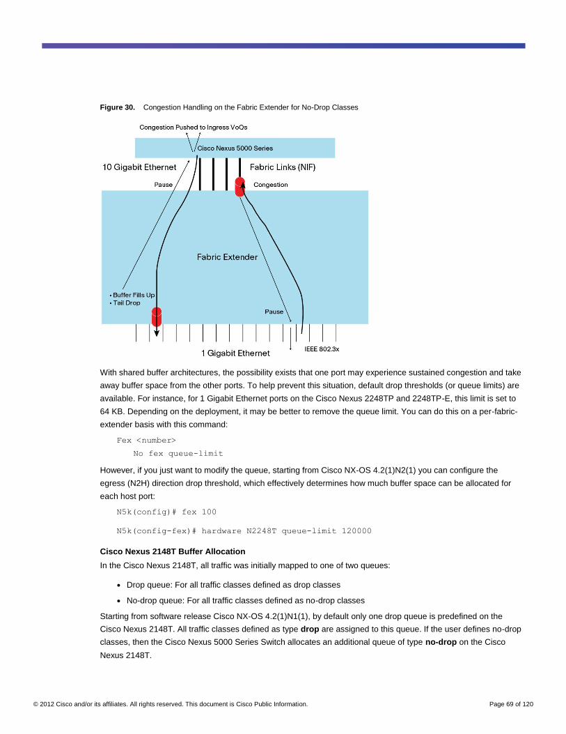
© 2012 Cisco and/or its affiliates. All rights reserved. This document is Cisco Public Information. Page 69 of 120
Figure 30. Congestion Handling on the Fabric Extender for No-Drop Classes
With shared buffer architectures, the possibility exists that one port may experience sustained congestion and take
away buffer space from the other ports. To help prevent this situation, default drop thresholds (or queue limits) are
available. For instance, for 1 Gigabit Ethernet ports on the Cisco Nexus 2248TP and 2248TP-E, this limit is set to
64 KB. Depending on the deployment, it may be better to remove the queue limit. You can do this on a per-fabric-
extender basis with this command:
Fex <number>
No fex queue-limit
However, if you just want to modify the queue, starting from Cisco NX-OS 4.2(1)N2(1) you can configure the
egress (N2H) direction drop threshold, which effectively determines how much buffer space can be allocated for
each host port:
N5k(config)# fex 100
N5k(config-fex)# hardware N2248T queue-limit 120000
Cisco Nexus 2148T Buffer Allocation
In the Cisco Nexus 2148T, all traffic was initially mapped to one of two queues:
● Drop queue: For all traffic classes defined as drop classes
● No-drop queue: For all traffic classes defined as no-drop classes
Starting from software release Cisco NX-OS 4.2(1)N1(1), by default only one drop queue is predefined on the
Cisco Nexus 2148T. All traffic classes defined as type drop are assigned to this queue. If the user defines no-drop
classes, then the Cisco Nexus 5000 Series Switch allocates an additional queue of type no-drop on the Cisco
Nexus 2148T.
© 2012 Cisco and/or its affiliates. All rights reserved. This document is Cisco Public Information. Page 70 of 120
In most deployments, the most important aspects of QoS on the Cisco Nexus 2148T apply to the N2H direction
because of the disparity in speed toward the 1 Gigabit Ethernet interfaces from, potentially, a multiple-Gigabit
source.
The ASIC of interest for this design has a 384-KB buffer for the N2H direction. This buffer is shared by four HIFs.
Every four front-panel ports on the Cisco Nexus 2148T share one buffer pool, so if you want to increase the buffer
space available to host ports, you can spread them over as many ASICs as possible.
Some buffer space is allocated for control-plane traffic. Therefore, a single server receiving traffic from the fabric
links could use all 320 KB. If four servers are connected per memory pool, then the maximum buffer space that
each server could potentially use (assuming that they are receiving traffic) is 80 KB.
If you define at least one no-drop traffic class, the available amount of shared buffer space becomes 160 KB for
every four ports.
For the H2N direction, the ASIC of interest is the one connecting the lower ASICs (that are shared by four ports)
with the fabric links. Just as for the N2H traffic, you have 320 KB of usable buffer space shared by 24 front-panel
ports. All traffic shares the same drop queue, and if the queue fills up, the fabric extender asserts a Pause (IEEE
802.3X) toward the server ports as previously described.
Cisco Nexus 2248TP Buffer Allocation
The Cisco Nexus 2248TP provides 800 KB of buffer space per ASIC. This ASIC is shared by eight HIF ports. Each
NIF port can access each one of these ASICs, and can use a maximum of 320 KB. Thus, for the Cisco Nexus
2248TP (in contrast to the Cisco Nexus 2148T), the more fabric links there are, the more buffer space is available.
With four NIF uplinks, the traffic can write to the full 800 KB of buffer space, which is shared by eight HIFs.
Note: Adding more fabric links to the connection between the Cisco Nexus 2000 Series and the upstream Cisco
Nexus 5000 Series is often useful to gain more buffering capacity. You gain capacity because even if buffers are
shared, there is a maximum limit on the amount of buffer space that a given NIF can use in case of congestion. For
instance, in the case of the Cisco Nexus 2248TP, a single NIF cannot use more than 320 KB out of the 800 KB
shared among the eight HIFs. If you connect all four NIFs, all 800 KB shared among all eight HIFs become
available.
Note: This discussion does not apply to the Cisco Nexus 2248TP-E; on the Cisco Nexus 2248TP-E, a single
fabric link can access the full shared memory buffer.
By default, there is a queue tail-drop threshold of 64 KB for the N2H direction, which can be removed with the no
fex queue-limit command. Figure 31 illustrates the architecture of a Cisco Nexus 2248TP with particular focus on
one of the six ASICs (each ASIC handles eight ports).
For the H2N direction, each group of eight ports shares a 480-KB buffer.
The Cisco Nexus 2248TP provides six different queues for the data traffic (two queues are used by control-plane
traffic just as on the Cisco Nexus 5000 Series Switches).
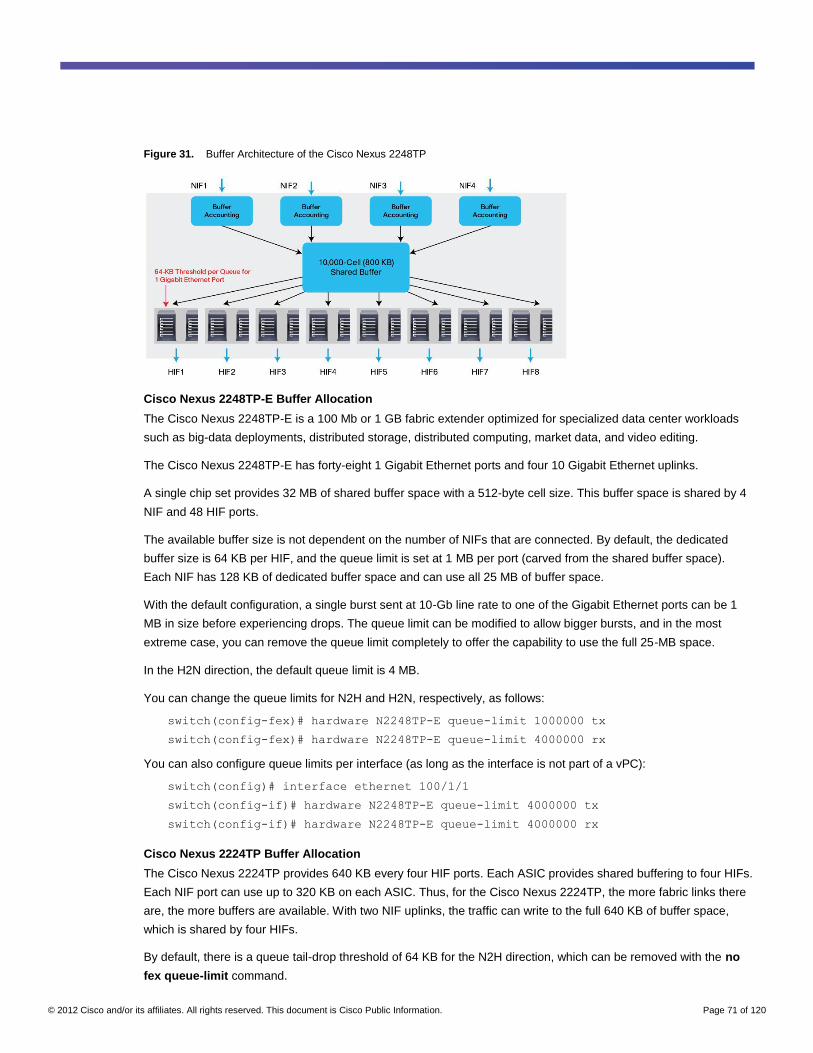
© 2012 Cisco and/or its affiliates. All rights reserved. This document is Cisco Public Information. Page 71 of 120
Figure 31. Buffer Architecture of the Cisco Nexus 2248TP
Cisco Nexus 2248TP-E Buffer Allocation
The Cisco Nexus 2248TP-E is a 100 Mb or 1 GB fabric extender optimized for specialized data center workloads
such as big-data deployments, distributed storage, distributed computing, market data, and video editing.
The Cisco Nexus 2248TP-E has forty-eight 1 Gigabit Ethernet ports and four 10 Gigabit Ethernet uplinks.
A single chip set provides 32 MB of shared buffer space with a 512-byte cell size. This buffer space is shared by 4
NIF and 48 HIF ports.
The available buffer size is not dependent on the number of NIFs that are connected. By default, the dedicated
buffer size is 64 KB per HIF, and the queue limit is set at 1 MB per port (carved from the shared buffer space).
Each NIF has 128 KB of dedicated buffer space and can use all 25 MB of buffer space.
With the default configuration, a single burst sent at 10-Gb line rate to one of the Gigabit Ethernet ports can be 1
MB in size before experiencing drops. The queue limit can be modified to allow bigger bursts, and in the most
extreme case, you can remove the queue limit completely to offer the capability to use the full 25-MB space.
In the H2N direction, the default queue limit is 4 MB.
You can change the queue limits for N2H and H2N, respectively, as follows:
switch(config-fex)# hardware N2248TP-E queue-limit 1000000 tx
switch(config-fex)# hardware N2248TP-E queue-limit 4000000 rx
You can also configure queue limits per interface (as long as the interface is not part of a vPC):
switch(config)# interface ethernet 100/1/1
switch(config-if)# hardware N2248TP-E queue-limit 4000000 tx
switch(config-if)# hardware N2248TP-E queue-limit 4000000 rx
Cisco Nexus 2224TP Buffer Allocation
The Cisco Nexus 2224TP provides 640 KB every four HIF ports. Each ASIC provides shared buffering to four HIFs.
Each NIF port can use up to 320 KB on each ASIC. Thus, for the Cisco Nexus 2224TP, the more fabric links there
are, the more buffers are available. With two NIF uplinks, the traffic can write to the full 640 KB of buffer space,
which is shared by four HIFs.
By default, there is a queue tail-drop threshold of 64 KB for the N2H direction, which can be removed with the no
fex queue-limit command.
© 2012 Cisco and/or its affiliates. All rights reserved. This document is Cisco Public Information. Page 72 of 120
For the H2N direction, each group of four ports shares a 480-KB buffer.
The Cisco Nexus 2224TP provides six different queues for the data traffic (two queues are used by control-plane
traffic just as on the Cisco Nexus 5000 Series Switches).
Cisco Nexus 2232PP and 2232TM Buffer Allocation
The Cisco Nexus 2232PP and 2232TM provide 1280 KB for each ASIC. Each ASIC is shared by eight HIF ports.
Each NIF port can access each ASIC and can use a maximum of 320 KB. Thus, for the Cisco Nexus 2232PP and
2232TM, the more fabric links there are, the more buffer space is available, up to the maximum of 1280 KB shared
by eight ports.
By default, there is a queue tail-drop threshold of 64 KB for the N2H direction, which can be removed with the no
fex queue-limit command.
For the H2N direction, each group of eight ports shares a 1280-KB buffer.
The Cisco Nexus 2232PP and 2232TM provide six different queues for the data traffic (two queues are used by
control-plane traffic just as on the Cisco Nexus 5000 Series Switches).
QoS Summary for Cisco Nexus 5000 Series with Fabric Extenders
Following is a short summary of QoS best practices for configuring QoS on Cisco Nexus fabric extenders. This
summary is equally applicable to all fabric extender models. Specific buffer sizes and considerations follow.
● Define an untagged cos configuration for fabric extender ports to assign server traffic to a proper class of
service for the H2N direction. You can further reclassify traffic with an ACL classification policy after the
traffic reaches the Cisco Nexus 5000 Series Switch.
● Be sure to configure a global network-qos policy (network-qos policies are always global) to map each
QoS group to a CoS. This configuration helps ensure that the egress scheduling policies (queuing polices)
operate on the N2H traffic.
● To configure H2N traffic prioritization and scheduling correctly, you need to define an ingress queuing
policy. When applied globally (that is, when applied to the system QoS), this policy automatically applies to
the H2N traffic when it is contending for the fabric ports.
● Identify your buffering requirements. For maximum shared buffer availability, connect all NIFs and make
sure to spread server ports over all available port ASICs.
● For bursty applications such as big-data applications and video editing, consider using the Cisco Nexus
2248TP-E, which offers 32 MB of shared buffer space.
● If you are using applications that generate single bursts that are bigger than the TCP receive window size,
you may want to disable the queue tail-drop threshold to allow the ports that are on the same ASIC to share
all the buffer space available.
To come up with a single QoS converged configuration for servers connected to both the Cisco Nexus 5000 Series
Switches and the fabric extenders, remember that fabric extenders work with CoS only, so a global classification
policy based on ACLs cannot be applied to the fabric extender ports, and as a result the prioritization and
scheduling defined in a queuing policy may not be applied.
© 2012 Cisco and/or its affiliates. All rights reserved. This document is Cisco Public Information. Page 73 of 120
Therefore, the correct way to define the QoS classification policy in the presence of fabric extenders is as follows:
● Define a global classification policy based on CoS. This policy is applied globally and associates CoS with
QoS groups, so that traffic coming from a fabric extender port and tagged using the untagged cos
command is assigned to a QoS group. If you did not configure the untagged CoS command, untagged
traffic is assigned to the class-default queue. If the classification policy includes other matching statements
such as match dscp or match ip access-group, it is rejected by the fabric extender, and classification
does not occur.
● You can define a Cisco Nexus 5000 Series interface classification policy for individual switches based on
ACLs. This policy is defined to classify traffic based on IP information, Layer 4 ports, and so on and to
associate this traffic with a QoS group. This policy is applied on a per-interface basis.
● A Cisco Nexus 2000 Series interface classification policy for individual fabric extenders is based on CoS
(untagged CoS) and can be complemented by an ACL-based classification, which is applied after traffic
reaches the Cisco Nexus 5000 Series Switch.
For example, if you need to provide classification for three classes plus class-default, you define a global
classification policy that applies to both Cisco Nexus 5000 Series ports and fabric extender ports as follows:
class-map type qos voice-global
match cos 5
class-map type qos critical-global
match cos 6
class-map type qos scavenger-global
match cos 1
You assign each CoS to a specific QoS group:
policy-map type qos classify-5020-global
class type qos voice-global
set qos-group 5
class type qos critical-global
set qos-group 3
class type qos scavenger-global
set qos-group 2
For the Cisco Nexus 5000 Series ports, since you can classify with ACL, you define the equivalent policy, which
matches on DSCP or ACLs, as follows:
class-map type qos match-any Voice
match dscp 40,46
class-map type qos Scavenger
match dscp 8
class-map type qos CriticalData
match dscp 18
policy-map type qos Classify-5020
class type qos Voice
set qos-group 5
class type qos CriticalData
set qos-group 3
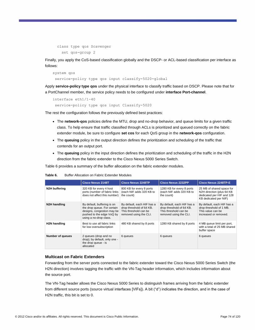
© 2012 Cisco and/or its affiliates. All rights reserved. This document is Cisco Public Information. Page 74 of 120
class type qos Scavenger
set qos-group 2
Finally, you apply the CoS-based classification globally and the DSCP- or ACL-based classification per interface as
follows:
system qos
service-policy type qos input classify-5020-global
Apply service-policy type qos under the physical interface to classify traffic based on DSCP. Please note that for
a PortChannel member, the service policy needs to be configured under interface Port-channel.
interface eth1/1-40
service-policy type qos input Classify-5020
The rest the configuration follows the previously defined best practices:
● The network-qos policies define the MTU, drop and no-drop behavior, and queue limits for a given traffic
class. To help ensure that traffic classified through ACLs is prioritized and queued correctly on the fabric
extender module, be sure to configure set cos for each QoS group in the network-qos configuration.
● The queuing policy in the output direction defines the prioritization and scheduling of the traffic that
contends for an output port.
● The queuing policy in the input direction defines the prioritization and scheduling of the traffic in the H2N
direction from the fabric extender to the Cisco Nexus 5000 Series Switch.
Table 6 provides a summary of the buffer allocation on the fabric extender modules.
Table 6. Buffer Allocation on Fabric Extender Modules
Cisco Nexus 2148T Cisco Nexus 2248TP Cisco Nexus 2232PP Cisco Nexus 2248TP-E
N2H buffering 320 KB for every 4 host ports (number of fabric links does not affect this number)
800 KB for every 8 ports (each NIF adds 320 KB to the count)
1280 KB for every 8 ports (each NIF adds 320 KB to the count)
25 MB of shared space for N2H direction (plus 64 KB dedicated per HIF and 128 KB dedicated per NIF)
N2H handling By default, buffering is on the drop queue. For certain designs, congestion may be pushed to the edge VoQ by using a no-drop class.
By default, each HIF has a drop threshold of 64 KB. This threshold can be removed using the CLI.
By default, each HIF has a drop threshold of 64 KB. This threshold can be removed using the CLI.
By default, each HIF has a drop threshold of 1 MB. This value can be increased or removed.
H2N handling Best to use all fabric links for low oversubscription
480 KB shared by 8 ports 1280 KB shared by 8 ports 4 MB queue limit per port, with a total of 25 MB shared buffer space
Number of queues 2 queues (drop and no drop); by default, only one - the drop queue - is allocated
6 queues 6 queues 6 queues
Multicast on Fabric Extenders
Forwarding from the server ports connected to the fabric extender toward the Cisco Nexus 5000 Series Switch (the
H2N direction) involves tagging the traffic with the VN-Tag header information, which includes information about
the source port.
The VN-Tag header allows the Cisco Nexus 5000 Series to distinguish frames arriving from the fabric extender
from different source ports (source virtual interfaces [VIFs]). A bit (“d”) indicates the direction, and in the case of
H2N traffic, this bit is set to 0.
© 2012 Cisco and/or its affiliates. All rights reserved. This document is Cisco Public Information. Page 75 of 120
The Cisco Nexus 5000 Series performs a Layer 2 MAC address table lookup based on the destination MAC
address of the frame, and it performs learning based on the source VIF and populates the destination VIF in case
the destination is attached to a fabric extender (a different fabric extender or the same one).
The traffic sent to a fabric extender (N2H) includes a VN-Tag, with the destination VIF information populated to
indicate the port on the fabric extender for which the traffic is destined, and with the “d” bit set to 1 to indicate the
N2H direction.
In case the traffic is multicast, the VN-Tag is configured with the “p” bit set to 1 to indicate that the content of the
destination VIF is not a destination port, but a pointer to a list of ports.
In the case of multicast traffic on the fabric extender, the replication occurs on the fabric extender itself for the ports
connected to the fabric extender, and not on the Cisco Nexus 5000 Series Switch.
Different multicast groups with fanouts (outgoing interface lists) that differ only based on fabric extender ports will
appear within a Cisco Nexus 5000 Series Switch as if they had the same fanout. In other words, what matters to
the Cisco Nexus 5000 Series in terms of fanout is the fabric interface to which the traffic goes, and not the HIF to
which it goes.
If a Cisco Nexus 5000 Series Switch sends a packet out the same physical port through which the packet entered
(for example, if the source and destination interfaces reside on the same physical interface), the Cisco Nexus 5000
Series Switch sets the L bit (loop bit) in the VN-Tag packet and copies the source VIF of the original packet in its
VN-Tag packet to the fabric extender. This process allows the source VIF interface to recognize its packet and
drop it.
Note that when the L bit is not set, the VN-Tag packet from the Cisco Nexus 5000 Series Switch carries zero in the
source VIF of the VN-Tag.
Given that the multicast indexes are based on the destinations that need to receive the frame (VLAN flood or
multicast group), when the source is part of the group, the looped check prevents the frame from returning to the
sender.
Topology Choices for Connecting Cisco Nexus 5000 and 2000 Series
A fabric extender can connect to the Cisco Nexus 5000 Series Switch with a single-homed topology, often referred
to as a straight-through connection without vPC, shown in Figure 32. With the single-homed topology, each fabric
extender is attached to a single Cisco Nexus 5000 Series Switch.
As of Cisco NX-OS 5.1(3)N1(1) up to 24 fabric extenders can be attached to a single Cisco Nexus 5500 platform
switch, for a total of up to 1152 host ports for each Cisco Nexus 5500 platform switch.
As of Cisco NX-OS 5.1(3)N1(1) up to 12 fabric extenders can be attached to a single Cisco Nexus 5020 or 5010
Switch, for a total of up to 576 host ports for each Cisco Nexus 5020 or 5010 Switch.
In a typical deployment, you would use two Cisco Nexus 5000 Series Switches for redundancy, and servers would
connect redundantly to a fabric extender that depends on n5k01 and another fabric extender that depends on
n5k02.
NIC teaming options supported in this topology are:
● Active-standby mode
● Active-active transmit load-balancing mode
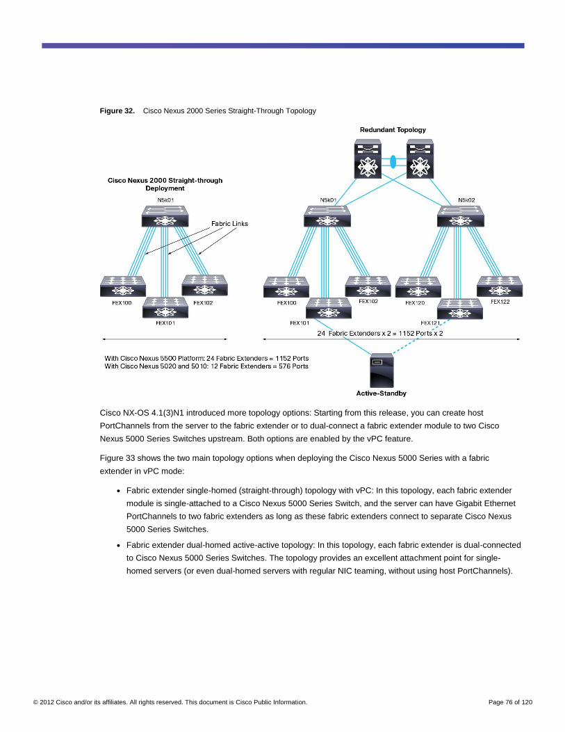
© 2012 Cisco and/or its affiliates. All rights reserved. This document is Cisco Public Information. Page 76 of 120
Figure 32. Cisco Nexus 2000 Series Straight-Through Topology
Cisco NX-OS 4.1(3)N1 introduced more topology options: Starting from this release, you can create host
PortChannels from the server to the fabric extender or to dual-connect a fabric extender module to two Cisco
Nexus 5000 Series Switches upstream. Both options are enabled by the vPC feature.
Figure 33 shows the two main topology options when deploying the Cisco Nexus 5000 Series with a fabric
extender in vPC mode:
● Fabric extender single-homed (straight-through) topology with vPC: In this topology, each fabric extender
module is single-attached to a Cisco Nexus 5000 Series Switch, and the server can have Gigabit Ethernet
PortChannels to two fabric extenders as long as these fabric extenders connect to separate Cisco Nexus
5000 Series Switches.
● Fabric extender dual-homed active-active topology: In this topology, each fabric extender is dual-connected
to Cisco Nexus 5000 Series Switches. The topology provides an excellent attachment point for single-
homed servers (or even dual-homed servers with regular NIC teaming, without using host PortChannels).
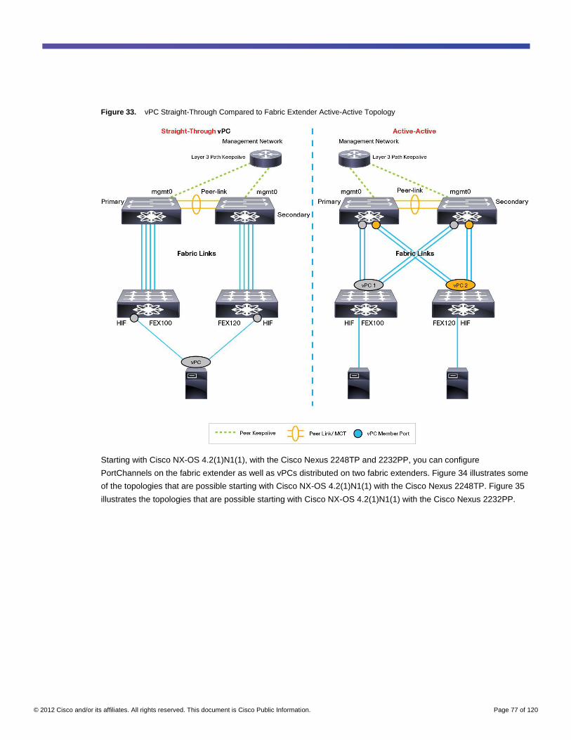
© 2012 Cisco and/or its affiliates. All rights reserved. This document is Cisco Public Information. Page 77 of 120
Figure 33. vPC Straight-Through Compared to Fabric Extender Active-Active Topology
Starting with Cisco NX-OS 4.2(1)N1(1), with the Cisco Nexus 2248TP and 2232PP, you can configure
PortChannels on the fabric extender as well as vPCs distributed on two fabric extenders. Figure 34 illustrates some
of the topologies that are possible starting with Cisco NX-OS 4.2(1)N1(1) with the Cisco Nexus 2248TP. Figure 35
illustrates the topologies that are possible starting with Cisco NX-OS 4.2(1)N1(1) with the Cisco Nexus 2232PP.
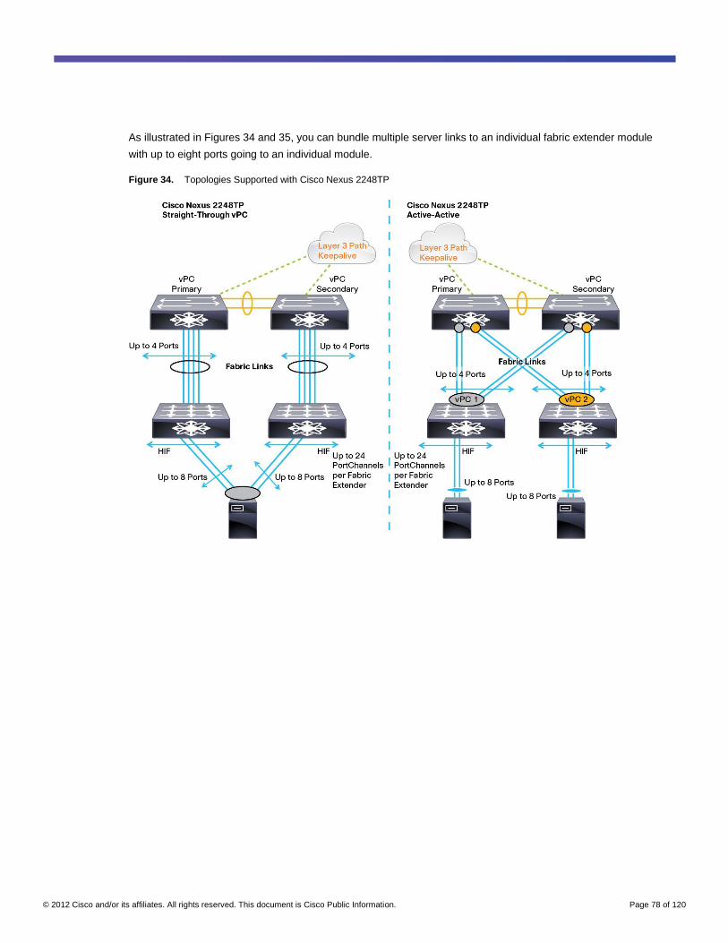
© 2012 Cisco and/or its affiliates. All rights reserved. This document is Cisco Public Information. Page 78 of 120
As illustrated in Figures 34 and 35, you can bundle multiple server links to an individual fabric extender module
with up to eight ports going to an individual module.
Figure 34. Topologies Supported with Cisco Nexus 2248TP
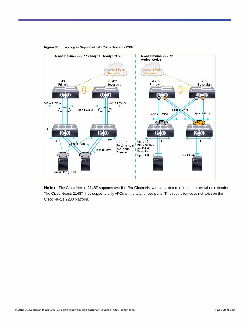
© 2012 Cisco and/or its affiliates. All rights reserved. This document is Cisco Public Information. Page 79 of 120
Figure 35. Topologies Supported with Cisco Nexus 2232PP
Note: The Cisco Nexus 2148T supports two-link PortChannels, with a maximum of one port per fabric extender.
The Cisco Nexus 2148T thus supports only vPCs with a total of two ports. This restriction does not exist on the
Cisco Nexus 2200 platform.
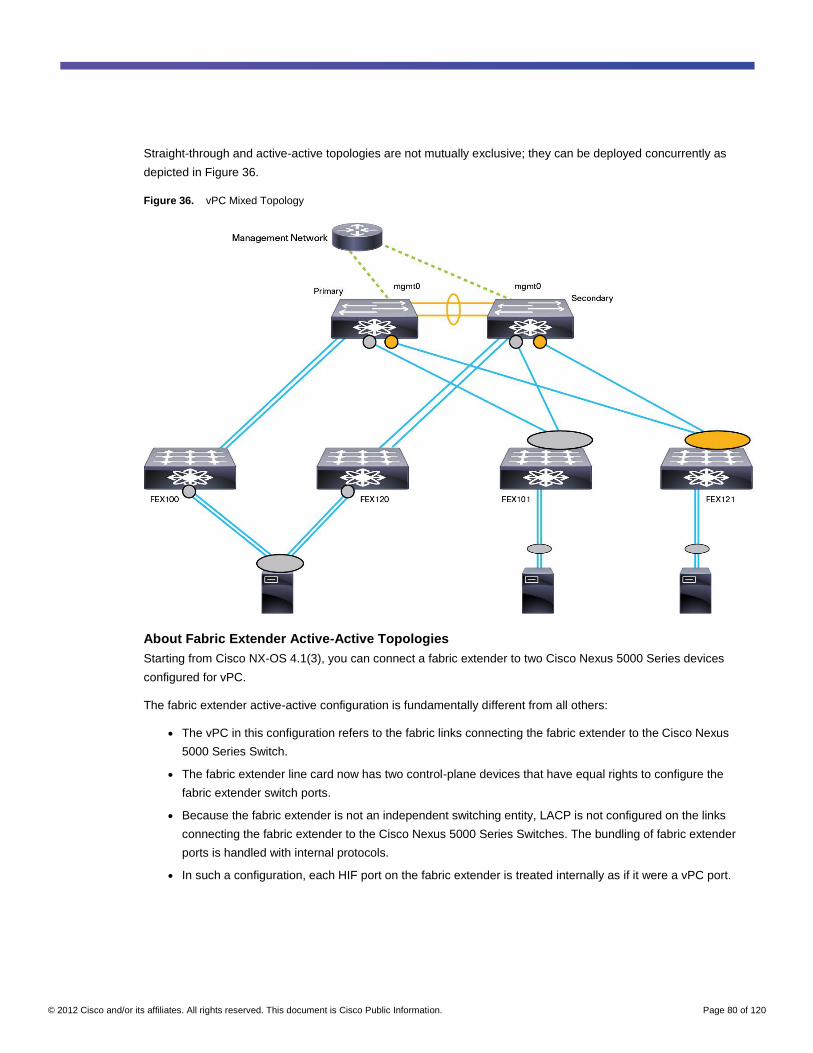
© 2012 Cisco and/or its affiliates. All rights reserved. This document is Cisco Public Information. Page 80 of 120
Straight-through and active-active topologies are not mutually exclusive; they can be deployed concurrently as
depicted in Figure 36.
Figure 36. vPC Mixed Topology
About Fabric Extender Active-Active Topologies
Starting from Cisco NX-OS 4.1(3), you can connect a fabric extender to two Cisco Nexus 5000 Series devices
configured for vPC.
The fabric extender active-active configuration is fundamentally different from all others:
● The vPC in this configuration refers to the fabric links connecting the fabric extender to the Cisco Nexus
5000 Series Switch.
● The fabric extender line card now has two control-plane devices that have equal rights to configure the
fabric extender switch ports.
● Because the fabric extender is not an independent switching entity, LACP is not configured on the links
connecting the fabric extender to the Cisco Nexus 5000 Series Switches. The bundling of fabric extender
ports is handled with internal protocols.
● In such a configuration, each HIF port on the fabric extender is treated internally as if it were a vPC port.
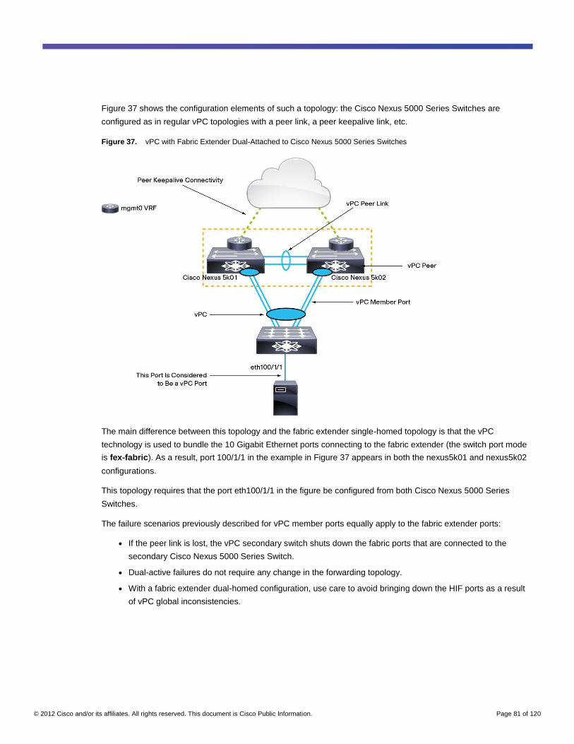
© 2012 Cisco and/or its affiliates. All rights reserved. This document is Cisco Public Information. Page 81 of 120
Figure 37 shows the configuration elements of such a topology: the Cisco Nexus 5000 Series Switches are
configured as in regular vPC topologies with a peer link, a peer keepalive link, etc.
Figure 37. vPC with Fabric Extender Dual-Attached to Cisco Nexus 5000 Series Switches
The main difference between this topology and the fabric extender single-homed topology is that the vPC
technology is used to bundle the 10 Gigabit Ethernet ports connecting to the fabric extender (the switch port mode
is fex-fabric). As a result, port 100/1/1 in the example in Figure 37 appears in both the nexus5k01 and nexus5k02
configurations.
This topology requires that the port eth100/1/1 in the figure be configured from both Cisco Nexus 5000 Series
Switches.
The failure scenarios previously described for vPC member ports equally apply to the fabric extender ports:
● If the peer link is lost, the vPC secondary switch shuts down the fabric ports that are connected to the
secondary Cisco Nexus 5000 Series Switch.
● Dual-active failures do not require any change in the forwarding topology.
● With a fabric extender dual-homed configuration, use care to avoid bringing down the HIF ports as a result
of vPC global inconsistencies.
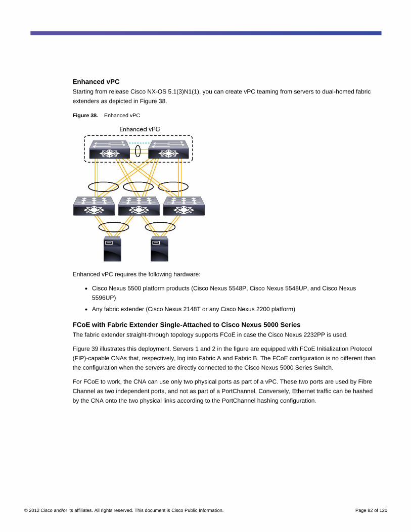
© 2012 Cisco and/or its affiliates. All rights reserved. This document is Cisco Public Information. Page 82 of 120
Enhanced vPC
Starting from release Cisco NX-OS 5.1(3)N1(1), you can create vPC teaming from servers to dual-homed fabric
extenders as depicted in Figure 38.
Figure 38. Enhanced vPC
Enhanced vPC requires the following hardware:
● Cisco Nexus 5500 platform products (Cisco Nexus 5548P, Cisco Nexus 5548UP, and Cisco Nexus
5596UP)
● Any fabric extender (Cisco Nexus 2148T or any Cisco Nexus 2200 platform)
FCoE with Fabric Extender Single-Attached to Cisco Nexus 5000 Series
The fabric extender straight-through topology supports FCoE in case the Cisco Nexus 2232PP is used.
Figure 39 illustrates this deployment. Servers 1 and 2 in the figure are equipped with FCoE Initialization Protocol
(FIP)-capable CNAs that, respectively, log into Fabric A and Fabric B. The FCoE configuration is no different than
the configuration when the servers are directly connected to the Cisco Nexus 5000 Series Switch.
For FCoE to work, the CNA can use only two physical ports as part of a vPC. These two ports are used by Fibre
Channel as two independent ports, and not as part of a PortChannel. Conversely, Ethernet traffic can be hashed
by the CNA onto the two physical links according to the PortChannel hashing configuration.
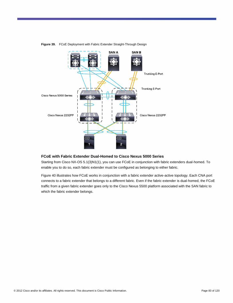
© 2012 Cisco and/or its affiliates. All rights reserved. This document is Cisco Public Information. Page 83 of 120
Figure 39. FCoE Deployment with Fabric Extender Straight-Through Design
FCoE with Fabric Extender Dual-Homed to Cisco Nexus 5000 Series
Starting from Cisco NX-OS 5.1(3)N1(1), you can use FCoE in conjunction with fabric extenders dual-homed. To
enable you to do so, each fabric extender must be configured as belonging to either fabric.
Figure 40 illustrates how FCoE works in conjunction with a fabric extender active-active topology. Each CNA port
connects to a fabric extender that belongs to a different fabric. Even if the fabric extender is dual-homed, the FCoE
traffic from a given fabric extender goes only to the Cisco Nexus 5500 platform associated with the SAN fabric to
which the fabric extender belongs.
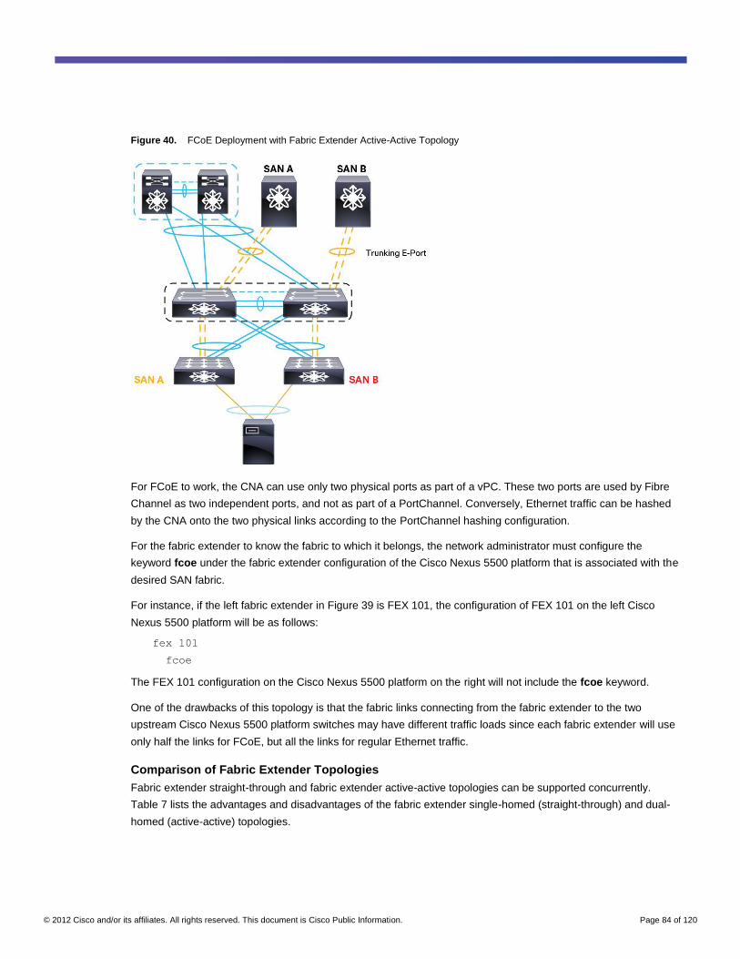
© 2012 Cisco and/or its affiliates. All rights reserved. This document is Cisco Public Information. Page 84 of 120
Figure 40. FCoE Deployment with Fabric Extender Active-Active Topology
For FCoE to work, the CNA can use only two physical ports as part of a vPC. These two ports are used by Fibre
Channel as two independent ports, and not as part of a PortChannel. Conversely, Ethernet traffic can be hashed
by the CNA onto the two physical links according to the PortChannel hashing configuration.
For the fabric extender to know the fabric to which it belongs, the network administrator must configure the
keyword fcoe under the fabric extender configuration of the Cisco Nexus 5500 platform that is associated with the
desired SAN fabric.
For instance, if the left fabric extender in Figure 39 is FEX 101, the configuration of FEX 101 on the left Cisco
Nexus 5500 platform will be as follows:
fex 101
fcoe
The FEX 101 configuration on the Cisco Nexus 5500 platform on the right will not include the fcoe keyword.
One of the drawbacks of this topology is that the fabric links connecting from the fabric extender to the two
upstream Cisco Nexus 5500 platform switches may have different traffic loads since each fabric extender will use
only half the links for FCoE, but all the links for regular Ethernet traffic.
Comparison of Fabric Extender Topologies
Fabric extender straight-through and fabric extender active-active topologies can be supported concurrently.
Table 7 lists the advantages and disadvantages of the fabric extender single-homed (straight-through) and dual-
homed (active-active) topologies.
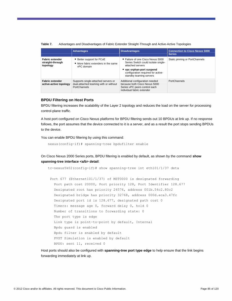
© 2012 Cisco and/or its affiliates. All rights reserved. This document is Cisco Public Information. Page 85 of 120
Table 7. Advantages and Disadvantages of Fabric Extender Straight-Through and Active-Active Topologies
Advantages Disadvantages Connection to Cisco Nexus 5000 Series
Fabric extender straight-through topology
● Better support for FCoE
● More fabric extenders in the same vPC domain
● Failure of one Cisco Nexus 5000 Series Switch could isolate single-attached servers
● vpc orphan-port suspend configuration required for active-standby teaming servers
Static pinning or PortChannels
Fabric extender active-active topology
Supports single-attached servers or dual-attached teaming with or without PortChannels
Additional configuration needed because both Cisco Nexus 5000 Series vPC peers control each individual fabric extender
PortChannels
BPDU Filtering on Host Ports
BPDU filtering increases the scalability of the Layer 2 topology and reduces the load on the server for processing
control-plane traffic.
A host port configured on Cisco Nexus platforms for BPDU filtering sends out 10 BPDUs at link up. If no response
follows, the port assumes that the device connected to it is a server, and as a result the port stops sending BPDUs
to the device.
You can enable BPDU filtering by using this command:
nexus(config-if)# spanning-tree bpdufilter enable
On Cisco Nexus 2000 Series ports, BPDU filtering is enabled by default, as shown by the command show
spanning-tree interface <a/b> detail:
tc-nexus5k02(config-if)# show spanning-tree int eth101/1/37 deta
Port 677 (Ethernet101/1/37) of MST0000 is designated forwarding
Port path cost 20000, Port priority 128, Port Identifier 128.677
Designated root has priority 24576, address 001b.54c2.80c2
Designated bridge has priority 32768, address 000d.eca3.47fc
Designated port id is 128.677, designated path cost 0
Timers: message age 0, forward delay 0, hold 0
Number of transitions to forwarding state: 0
The port type is edge
Link type is point-to-point by default, Internal
Bpdu guard is enabled
Bpdu filter is enabled by default
PVST Simulation is enabled by default
BPDU: sent 11, received 0
Host ports should also be configured with spanning-tree port type edge to help ensure that the link begins
forwarding immediately at link up.
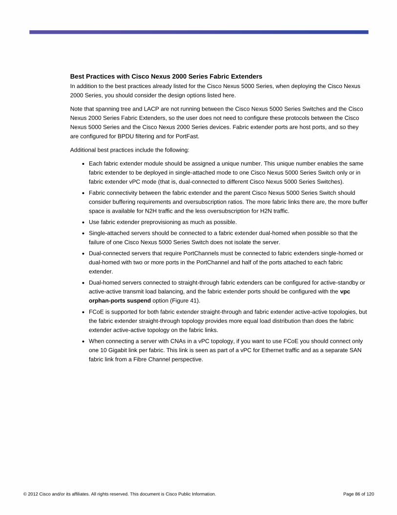
© 2012 Cisco and/or its affiliates. All rights reserved. This document is Cisco Public Information. Page 86 of 120
Best Practices with Cisco Nexus 2000 Series Fabric Extenders
In addition to the best practices already listed for the Cisco Nexus 5000 Series, when deploying the Cisco Nexus
2000 Series, you should consider the design options listed here.
Note that spanning tree and LACP are not running between the Cisco Nexus 5000 Series Switches and the Cisco
Nexus 2000 Series Fabric Extenders, so the user does not need to configure these protocols between the Cisco
Nexus 5000 Series and the Cisco Nexus 2000 Series devices. Fabric extender ports are host ports, and so they
are configured for BPDU filtering and for PortFast.
Additional best practices include the following:
● Each fabric extender module should be assigned a unique number. This unique number enables the same
fabric extender to be deployed in single-attached mode to one Cisco Nexus 5000 Series Switch only or in
fabric extender vPC mode (that is, dual-connected to different Cisco Nexus 5000 Series Switches).
● Fabric connectivity between the fabric extender and the parent Cisco Nexus 5000 Series Switch should
consider buffering requirements and oversubscription ratios. The more fabric links there are, the more buffer
space is available for N2H traffic and the less oversubscription for H2N traffic.
● Use fabric extender preprovisioning as much as possible.
● Single-attached servers should be connected to a fabric extender dual-homed when possible so that the
failure of one Cisco Nexus 5000 Series Switch does not isolate the server.
● Dual-connected servers that require PortChannels must be connected to fabric extenders single-homed or
dual-homed with two or more ports in the PortChannel and half of the ports attached to each fabric
extender.
● Dual-homed servers connected to straight-through fabric extenders can be configured for active-standby or
active-active transmit load balancing, and the fabric extender ports should be configured with the vpc
orphan-ports suspend option (Figure 41).
● FCoE is supported for both fabric extender straight-through and fabric extender active-active topologies, but
the fabric extender straight-through topology provides more equal load distribution than does the fabric
extender active-active topology on the fabric links.
● When connecting a server with CNAs in a vPC topology, if you want to use FCoE you should connect only
one 10 Gigabit link per fabric. This link is seen as part of a vPC for Ethernet traffic and as a separate SAN
fabric link from a Fibre Channel perspective.
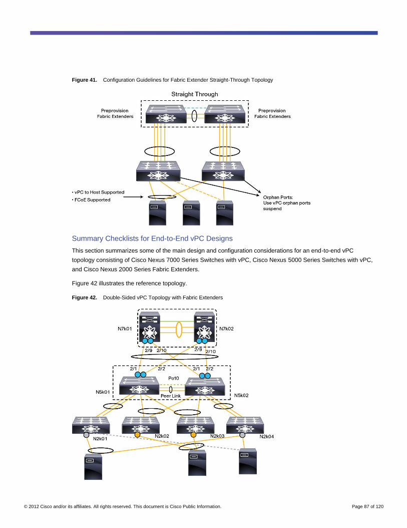
© 2012 Cisco and/or its affiliates. All rights reserved. This document is Cisco Public Information. Page 87 of 120
Figure 41. Configuration Guidelines for Fabric Extender Straight-Through Topology
Summary Checklists for End-to-End vPC Designs
This section summarizes some of the main design and configuration considerations for an end-to-end vPC
topology consisting of Cisco Nexus 7000 Series Switches with vPC, Cisco Nexus 5000 Series Switches with vPC,
and Cisco Nexus 2000 Series Fabric Extenders.
Figure 42 illustrates the reference topology.
Figure 42. Double-Sided vPC Topology with Fabric Extenders
© 2012 Cisco and/or its affiliates. All rights reserved. This document is Cisco Public Information. Page 88 of 120
vPC Domain Checklist
vPC configuration best practices include the following steps:
● Define domains.
◦ Make sure the domain ID differs between vPC domains.
● Establish peer keepalive connectivity.
◦ Be sure to use an out-of-band keepalive path such as mgmt0 over a management network.
● Create a peer link.
◦ Use two or more 10 Gigabit Ethernet ports.
● Do not forget that putting a VLAN on a vPC requires that the VLAN be on the peer link, too.
● Create vPCs.
● Monitor the status of consistency checks.
● Enable autorecovery.
● Make sure that the Graceful Consistency Check feature is enabled.
● Configure vpc delay restore.
● Configure vpc orphan-ports suspend on orphan ports that connect to NIC teaming in active-standby
mode.
● Consider the use of enhanced vPC for setting up PortChannels for servers to fabric extenders in an active-
active configuration.
LACP Checklist
LACP best practices include the following steps:
● Create a single PortChannel using LACP between the aggregation and access layers.
● Use lacp suspend-individual for switch links.
● Disable lacp suspend-individual for ports that require Preboot Execution Environment (PXE) booting and
for server ports in general.
● Evaluate the use of LACP fast rate (for HP servers, for instance) and consider the effect on ISSU.
Spanning-Tree Checklist
Spanning-tree best practices include the following steps:
● If you use the peer switch function, then define identical priorities on the aggregation layer switches, to
make those switches the root.
● Do not use Bridge Assurance (that is, do not use spanning-tree port type network; use spanning-tree
port type normal instead).
● Keep the default spanning-tree priorities on the access layer switches.
● Use UDLD normal mode.
● Enable errdisable recovery.
● If you are using MST, make sure that VLAN range configurations are consistent.
● When using MST, be aware of the Cisco NX-OS VLAN range and of the global Type 1 inconsistencies;
hence, configure VLAN-to-region mappings from day 1.
© 2012 Cisco and/or its affiliates. All rights reserved. This document is Cisco Public Information. Page 89 of 120
● Use pathcost method long.
● Configure the spanning-tree port type edge or port type edge trunk.
QoS Checklist
QoS best practices include the following steps:
● If you are using FCoE at the access layer, be sure to map FCoE service policies with the no-drop class.
● Add fabric extender uplinks to achieve the greatest buffer size and lower oversubscription.
● Spread server ports over different port ASICs on the fabric extender if you want more buffer space.
● Tune the queue limits for fabric extender ports.
● Consider using the Cisco Nexus 2248TP-E for particular applications such as video editing and Panasas
storage.
Multicast Checklist
Multicast best practices include the following steps:
● Do not disable IGMP snooping.
● If necessary, you can configure multicast ports manually, or you can define a querier.
● Prune multicast traffic from the peer link (configure no ip igmp snooping mrouter vpc-peer-link).
Manageability Considerations
Using Port Profiles
Port profiles provide a template configuration that can then be applied identically to multiple interfaces. The
Ethernet port profile by default is Layer 2 on the Cisco Nexus 5000 Series.
This sample configuration illustrates the configuration template provided by port profiles:
port-profile type ethernet accessvlan
switchport access vlan 50
spanning-tree port type edge
state enabled
Whenever you configure shut or no shut from the port profile, this setting is propagated to the port. Also, state
enabled must be configured for the port profile configuration to take effect.
Note: For more information about port profiles, please refer to the following link:
http://www.cisco.com/en/US/docs/switches/datacenter/nexus5000/sw/layer2/502_n1_1/Cisco_n5k_layer2_config_g
d_rel_502_N1_1_chapter3.html#topic_41F03388132246CA993975F8EAD731DC.
Using Configuration Synchronization
Starting from Cisco NX-OS 5.0(2)N1(1), vPC-based configurations can be replicated among Cisco Nexus 5000
Series vPC peers by using the configuration synchronization (config-sync) feature. Config-sync provides a
mechanism for synchronizing configurations. It does so by using the concept of a switch profile; the switch profile is
used to create the configuration file that is then applied to the local vPC peer and the remote vPC peer.
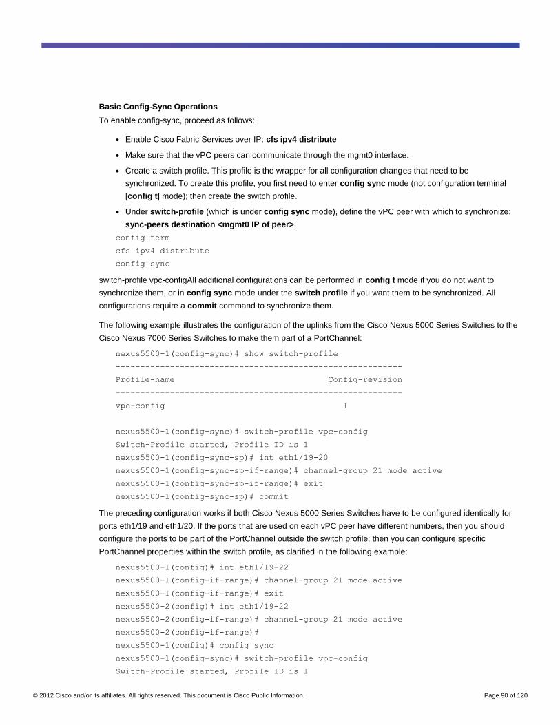
© 2012 Cisco and/or its affiliates. All rights reserved. This document is Cisco Public Information. Page 90 of 120
Basic Config-Sync Operations
To enable config-sync, proceed as follows:
● Enable Cisco Fabric Services over IP: cfs ipv4 distribute
● Make sure that the vPC peers can communicate through the mgmt0 interface.
● Create a switch profile. This profile is the wrapper for all configuration changes that need to be
synchronized. To create this profile, you first need to enter config sync mode (not configuration terminal
[config t] mode); then create the switch profile.
● Under switch-profile (which is under config sync mode), define the vPC peer with which to synchronize:
sync-peers destination <mgmt0 IP of peer>.
config term
cfs ipv4 distribute
config sync
switch-profile vpc-configAll additional configurations can be performed in config t mode if you do not want to
synchronize them, or in config sync mode under the switch profile if you want them to be synchronized. All
configurations require a commit command to synchronize them.
The following example illustrates the configuration of the uplinks from the Cisco Nexus 5000 Series Switches to the
Cisco Nexus 7000 Series Switches to make them part of a PortChannel:
nexus5500-1(config-sync)# show switch-profile
----------------------------------------------------------
Profile-name Config-revision
----------------------------------------------------------
vpc-config 1
nexus5500-1(config-sync)# switch-profile vpc-config
Switch-Profile started, Profile ID is 1
nexus5500-1(config-sync-sp)# int eth1/19-20
nexus5500-1(config-sync-sp-if-range)# channel-group 21 mode active
nexus5500-1(config-sync-sp-if-range)# exit
nexus5500-1(config-sync-sp)# commit
The preceding configuration works if both Cisco Nexus 5000 Series Switches have to be configured identically for
ports eth1/19 and eth1/20. If the ports that are used on each vPC peer have different numbers, then you should
configure the ports to be part of the PortChannel outside the switch profile; then you can configure specific
PortChannel properties within the switch profile, as clarified in the following example:
nexus5500-1(config)# int eth1/19-22
nexus5500-1(config-if-range)# channel-group 21 mode active
nexus5500-1(config-if-range)# exit
nexus5500-2(config)# int eth1/19-22
nexus5500-2(config-if-range)# channel-group 21 mode active
nexus5500-2(config-if-range)#
nexus5500-1(config)# config sync
nexus5500-1(config-sync)# switch-profile vpc-config
Switch-Profile started, Profile ID is 1
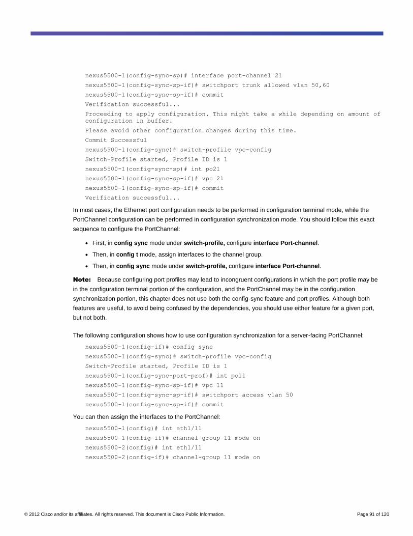
© 2012 Cisco and/or its affiliates. All rights reserved. This document is Cisco Public Information. Page 91 of 120
nexus5500-1(config-sync-sp)# interface port-channel 21
nexus5500-1(config-sync-sp-if)# switchport trunk allowed vlan 50,60
nexus5500-1(config-sync-sp-if)# commit
Verification successful...
Proceeding to apply configuration. This might take a while depending on amount of
configuration in buffer.
Please avoid other configuration changes during this time.
Commit Successful
nexus5500-1(config-sync)# switch-profile vpc-config
Switch-Profile started, Profile ID is 1
nexus5500-1(config-sync-sp)# int po21
nexus5500-1(config-sync-sp-if)# vpc 21
nexus5500-1(config-sync-sp-if)# commit
Verification successful...
In most cases, the Ethernet port configuration needs to be performed in configuration terminal mode, while the
PortChannel configuration can be performed in configuration synchronization mode. You should follow this exact
sequence to configure the PortChannel:
● First, in config sync mode under switch-profile, configure interface Port-channel.
● Then, in config t mode, assign interfaces to the channel group.
● Then, in config sync mode under switch-profile, configure interface Port-channel.
Note: Because configuring port profiles may lead to incongruent configurations in which the port profile may be
in the configuration terminal portion of the configuration, and the PortChannel may be in the configuration
synchronization portion, this chapter does not use both the config-sync feature and port profiles. Although both
features are useful, to avoid being confused by the dependencies, you should use either feature for a given port,
but not both.
The following configuration shows how to use configuration synchronization for a server-facing PortChannel:
nexus5500-1(config-if)# config sync
nexus5500-1(config-sync)# switch-profile vpc-config
Switch-Profile started, Profile ID is 1
nexus5500-1(config-sync-port-prof)# int po11
nexus5500-1(config-sync-sp-if)# vpc 11
nexus5500-1(config-sync-sp-if)# switchport access vlan 50
nexus5500-1(config-sync-sp-if)# commit
You can then assign the interfaces to the PortChannel:
nexus5500-1(config)# int eth1/11
nexus5500-1(config-if)# channel-group 11 mode on
nexus5500-2(config)# int eth1/11
nexus5500-2(config-if)# channel-group 11 mode on
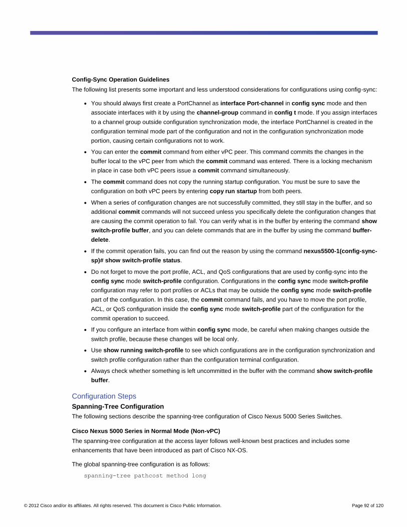
© 2012 Cisco and/or its affiliates. All rights reserved. This document is Cisco Public Information. Page 92 of 120
Config-Sync Operation Guidelines
The following list presents some important and less understood considerations for configurations using config-sync:
● You should always first create a PortChannel as interface Port-channel in config sync mode and then
associate interfaces with it by using the channel-group command in config t mode. If you assign interfaces
to a channel group outside configuration synchronization mode, the interface PortChannel is created in the
configuration terminal mode part of the configuration and not in the configuration synchronization mode
portion, causing certain configurations not to work.
● You can enter the commit command from either vPC peer. This command commits the changes in the
buffer local to the vPC peer from which the commit command was entered. There is a locking mechanism
in place in case both vPC peers issue a commit command simultaneously.
● The commit command does not copy the running startup configuration. You must be sure to save the
configuration on both vPC peers by entering copy run startup from both peers.
● When a series of configuration changes are not successfully committed, they still stay in the buffer, and so
additional commit commands will not succeed unless you specifically delete the configuration changes that
are causing the commit operation to fail. You can verify what is in the buffer by entering the command show
switch-profile buffer, and you can delete commands that are in the buffer by using the command buffer-
delete.
● If the commit operation fails, you can find out the reason by using the command nexus5500-1(config-sync-
sp)# show switch-profile status.
● Do not forget to move the port profile, ACL, and QoS configurations that are used by config-sync into the
config sync mode switch-profile configuration. Configurations in the config sync mode switch-profile
configuration may refer to port profiles or ACLs that may be outside the config sync mode switch-profile
part of the configuration. In this case, the commit command fails, and you have to move the port profile,
ACL, or QoS configuration inside the config sync mode switch-profile part of the configuration for the
commit operation to succeed.
● If you configure an interface from within config sync mode, be careful when making changes outside the
switch profile, because these changes will be local only.
● Use show running switch-profile to see which configurations are in the configuration synchronization and
switch profile configuration rather than the configuration terminal configuration.
● Always check whether something is left uncommitted in the buffer with the command show switch-profile
buffer.
Configuration Steps
Spanning-Tree Configuration
The following sections describe the spanning-tree configuration of Cisco Nexus 5000 Series Switches.
Cisco Nexus 5000 Series in Normal Mode (Non-vPC)
The spanning-tree configuration at the access layer follows well-known best practices and includes some
enhancements that have been introduced as part of Cisco NX-OS.
The global spanning-tree configuration is as follows:
spanning-tree pathcost method long
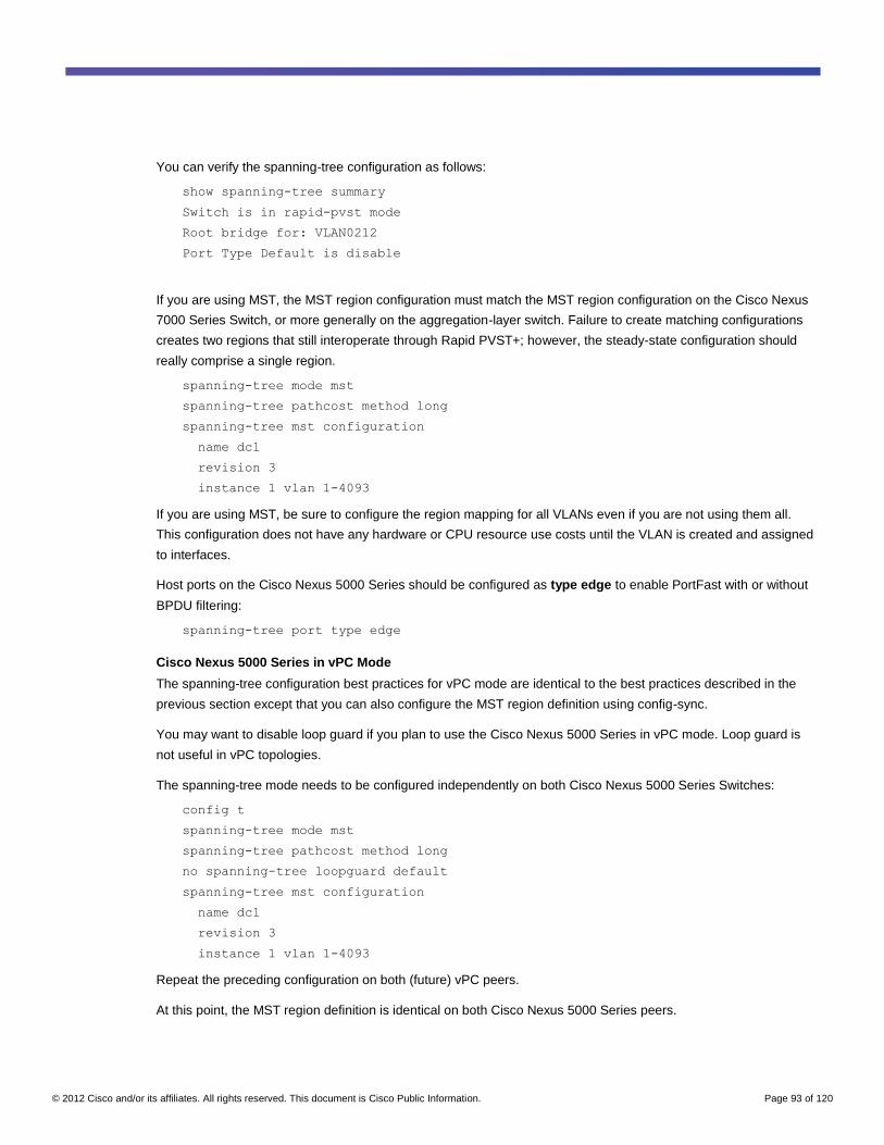
© 2012 Cisco and/or its affiliates. All rights reserved. This document is Cisco Public Information. Page 93 of 120
You can verify the spanning-tree configuration as follows:
show spanning-tree summary
Switch is in rapid-pvst mode
Root bridge for: VLAN0212
Port Type Default is disable
If you are using MST, the MST region configuration must match the MST region configuration on the Cisco Nexus
7000 Series Switch, or more generally on the aggregation-layer switch. Failure to create matching configurations
creates two regions that still interoperate through Rapid PVST+; however, the steady-state configuration should
really comprise a single region.
spanning-tree mode mst
spanning-tree pathcost method long
spanning-tree mst configuration
name dc1
revision 3
instance 1 vlan 1-4093
If you are using MST, be sure to configure the region mapping for all VLANs even if you are not using them all.
This configuration does not have any hardware or CPU resource use costs until the VLAN is created and assigned
to interfaces.
Host ports on the Cisco Nexus 5000 Series should be configured as type edge to enable PortFast with or without
BPDU filtering:
spanning-tree port type edge
Cisco Nexus 5000 Series in vPC Mode
The spanning-tree configuration best practices for vPC mode are identical to the best practices described in the
previous section except that you can also configure the MST region definition using config-sync.
You may want to disable loop guard if you plan to use the Cisco Nexus 5000 Series in vPC mode. Loop guard is
not useful in vPC topologies.
The spanning-tree mode needs to be configured independently on both Cisco Nexus 5000 Series Switches:
config t
spanning-tree mode mst
spanning-tree pathcost method long
no spanning-tree loopguard default
spanning-tree mst configuration
name dc1
revision 3
instance 1 vlan 1-4093
Repeat the preceding configuration on both (future) vPC peers.
At this point, the MST region definition is identical on both Cisco Nexus 5000 Series peers.
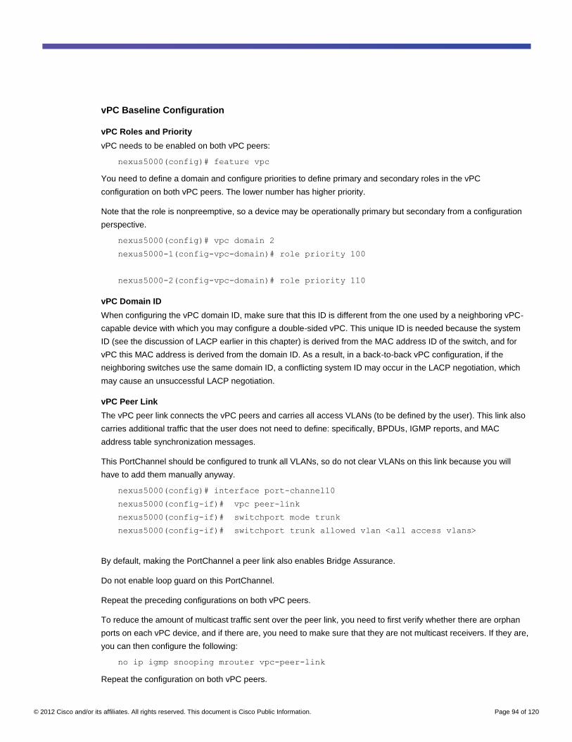
© 2012 Cisco and/or its affiliates. All rights reserved. This document is Cisco Public Information. Page 94 of 120
vPC Baseline Configuration
vPC Roles and Priority
vPC needs to be enabled on both vPC peers:
nexus5000(config)# feature vpc
You need to define a domain and configure priorities to define primary and secondary roles in the vPC
configuration on both vPC peers. The lower number has higher priority.
Note that the role is nonpreemptive, so a device may be operationally primary but secondary from a configuration
perspective.
nexus5000(config)# vpc domain 2
nexus5000-1(config-vpc-domain)# role priority 100
nexus5000-2(config-vpc-domain)# role priority 110
vPC Domain ID
When configuring the vPC domain ID, make sure that this ID is different from the one used by a neighboring vPC-
capable device with which you may configure a double-sided vPC. This unique ID is needed because the system
ID (see the discussion of LACP earlier in this chapter) is derived from the MAC address ID of the switch, and for
vPC this MAC address is derived from the domain ID. As a result, in a back-to-back vPC configuration, if the
neighboring switches use the same domain ID, a conflicting system ID may occur in the LACP negotiation, which
may cause an unsuccessful LACP negotiation.
vPC Peer Link
The vPC peer link connects the vPC peers and carries all access VLANs (to be defined by the user). This link also
carries additional traffic that the user does not need to define: specifically, BPDUs, IGMP reports, and MAC
address table synchronization messages.
This PortChannel should be configured to trunk all VLANs, so do not clear VLANs on this link because you will
have to add them manually anyway.
nexus5000(config)# interface port-channel10
nexus5000(config-if)# vpc peer-link
nexus5000(config-if)# switchport mode trunk
nexus5000(config-if)# switchport trunk allowed vlan <all access vlans>
By default, making the PortChannel a peer link also enables Bridge Assurance.
Do not enable loop guard on this PortChannel.
Repeat the preceding configurations on both vPC peers.
To reduce the amount of multicast traffic sent over the peer link, you need to first verify whether there are orphan
ports on each vPC device, and if there are, you need to make sure that they are not multicast receivers. If they are,
you can then configure the following:
no ip igmp snooping mrouter vpc-peer-link
Repeat the configuration on both vPC peers.
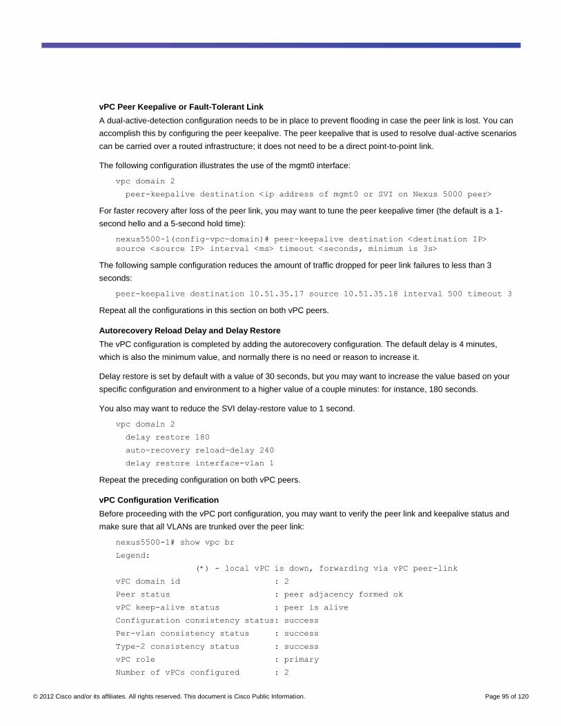
© 2012 Cisco and/or its affiliates. All rights reserved. This document is Cisco Public Information. Page 95 of 120
vPC Peer Keepalive or Fault-Tolerant Link
A dual-active-detection configuration needs to be in place to prevent flooding in case the peer link is lost. You can
accomplish this by configuring the peer keepalive. The peer keepalive that is used to resolve dual-active scenarios
can be carried over a routed infrastructure; it does not need to be a direct point-to-point link.
The following configuration illustrates the use of the mgmt0 interface:
vpc domain 2
peer-keepalive destination <ip address of mgmt0 or SVI on Nexus 5000 peer>
For faster recovery after loss of the peer link, you may want to tune the peer keepalive timer (the default is a 1-
second hello and a 5-second hold time):
nexus5500-1(config-vpc-domain)# peer-keepalive destination <destination IP>
source <source IP> interval <ms> timeout <seconds, minimum is 3s>
The following sample configuration reduces the amount of traffic dropped for peer link failures to less than 3
seconds:
peer-keepalive destination 10.51.35.17 source 10.51.35.18 interval 500 timeout 3
Repeat all the configurations in this section on both vPC peers.
Autorecovery Reload Delay and Delay Restore
The vPC configuration is completed by adding the autorecovery configuration. The default delay is 4 minutes,
which is also the minimum value, and normally there is no need or reason to increase it.
Delay restore is set by default with a value of 30 seconds, but you may want to increase the value based on your
specific configuration and environment to a higher value of a couple minutes: for instance, 180 seconds.
You also may want to reduce the SVI delay-restore value to 1 second.
vpc domain 2
delay restore 180
auto-recovery reload-delay 240
delay restore interface-vlan 1
Repeat the preceding configuration on both vPC peers.
vPC Configuration Verification
Before proceeding with the vPC port configuration, you may want to verify the peer link and keepalive status and
make sure that all VLANs are trunked over the peer link:
nexus5500-1# show vpc br
Legend:
(*) - local vPC is down, forwarding via vPC peer-link
vPC domain id : 2
Peer status : peer adjacency formed ok
vPC keep-alive status : peer is alive
Configuration consistency status: success
Per-vlan consistency status : success
Type-2 consistency status : success
vPC role : primary
Number of vPCs configured : 2
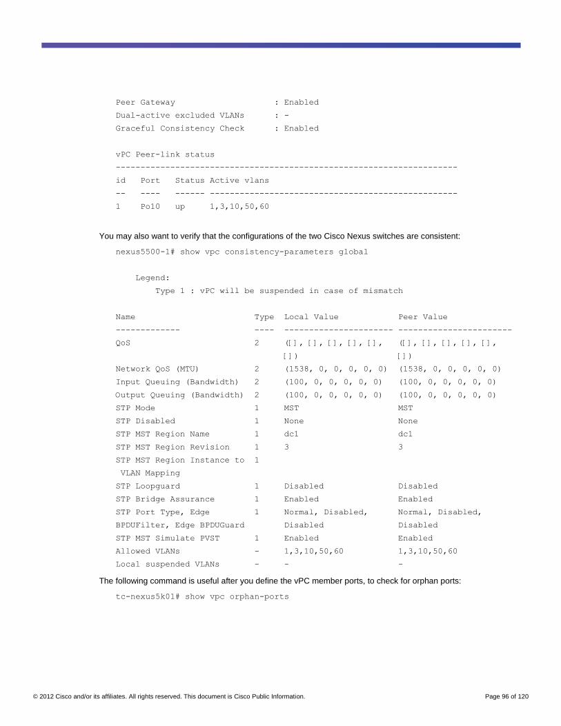
© 2012 Cisco and/or its affiliates. All rights reserved. This document is Cisco Public Information. Page 96 of 120
Peer Gateway : Enabled
Dual-active excluded VLANs : -
Graceful Consistency Check : Enabled
vPC Peer-link status
---------------------------------------------------------------------
id Port Status Active vlans
-- ---- ------ --------------------------------------------------
1 Po10 up 1,3,10,50,60
You may also want to verify that the configurations of the two Cisco Nexus switches are consistent:
nexus5500-1# show vpc consistency-parameters global
Legend:
Type 1 : vPC will be suspended in case of mismatch
Name Type Local Value Peer Value
------------- ---- ---------------------- -----------------------
QoS 2 ([], [], [], [], [], ([], [], [], [], [],
[]) [])
Network QoS (MTU) 2 (1538, 0, 0, 0, 0, 0) (1538, 0, 0, 0, 0, 0)
Input Queuing (Bandwidth) 2 (100, 0, 0, 0, 0, 0) (100, 0, 0, 0, 0, 0)
Output Queuing (Bandwidth) 2 (100, 0, 0, 0, 0, 0) (100, 0, 0, 0, 0, 0)
STP Mode 1 MST MST
STP Disabled 1 None None
STP MST Region Name 1 dc1 dc1
STP MST Region Revision 1 3 3
STP MST Region Instance to 1
VLAN Mapping
STP Loopguard 1 Disabled Disabled
STP Bridge Assurance 1 Enabled Enabled
STP Port Type, Edge 1 Normal, Disabled, Normal, Disabled,
BPDUFilter, Edge BPDUGuard Disabled Disabled
STP MST Simulate PVST 1 Enabled Enabled
Allowed VLANs - 1,3,10,50,60 1,3,10,50,60
Local suspended VLANs - - -
The following command is useful after you define the vPC member ports, to check for orphan ports:
tc-nexus5k01# show vpc orphan-ports
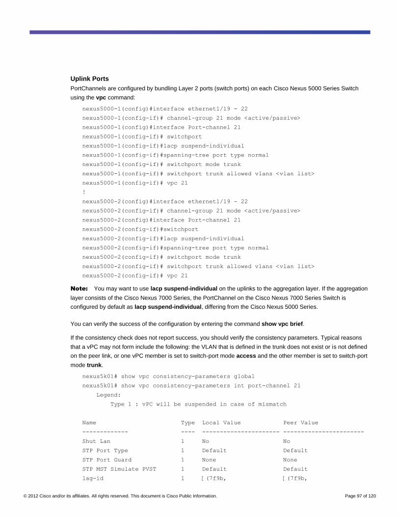
© 2012 Cisco and/or its affiliates. All rights reserved. This document is Cisco Public Information. Page 97 of 120
Uplink Ports
PortChannels are configured by bundling Layer 2 ports (switch ports) on each Cisco Nexus 5000 Series Switch
using the vpc command:
nexus5000-1(config)#interface ethernet1/19 - 22
nexus5000-1(config-if)# channel-group 21 mode <active/passive>
nexus5000-1(config)#interface Port-channel 21
nexus5000-1(config-if)# switchport
nexus5000-1(config-if)#lacp suspend-individual
nexus5000-1(config-if)#spanning-tree port type normal
nexus5000-1(config-if)# switchport mode trunk
nexus5000-1(config-if)# switchport trunk allowed vlans <vlan list>
nexus5000-1(config-if)# vpc 21
!
nexus5000-2(config)#interface ethernet1/19 - 22
nexus5000-2(config-if)# channel-group 21 mode <active/passive>
nexus5000-2(config)#interface Port-channel 21
nexus5000-2(config-if)#switchport
nexus5000-2(config-if)#lacp suspend-individual
nexus5000-2(config-if)#spanning-tree port type normal
nexus5000-2(config-if)# switchport mode trunk
nexus5000-2(config-if)# switchport trunk allowed vlans <vlan list>
nexus5000-2(config-if)# vpc 21
Note: You may want to use lacp suspend-individual on the uplinks to the aggregation layer. If the aggregation
layer consists of the Cisco Nexus 7000 Series, the PortChannel on the Cisco Nexus 7000 Series Switch is
configured by default as lacp suspend-individual, differing from the Cisco Nexus 5000 Series.
You can verify the success of the configuration by entering the command show vpc brief.
If the consistency check does not report success, you should verify the consistency parameters. Typical reasons
that a vPC may not form include the following: the VLAN that is defined in the trunk does not exist or is not defined
on the peer link, or one vPC member is set to switch-port mode access and the other member is set to switch-port
mode trunk.
nexus5k01# show vpc consistency-parameters global
nexus5k01# show vpc consistency-parameters int port-channel 21
Legend:
Type 1 : vPC will be suspended in case of mismatch
Name Type Local Value Peer Value
------------- ---- ---------------------- -----------------------
Shut Lan 1 No No
STP Port Type 1 Default Default
STP Port Guard 1 None None
STP MST Simulate PVST 1 Default Default
lag-id 1 [(7f9b, [(7f9b,
© 2012 Cisco and/or its affiliates. All rights reserved. This document is Cisco Public Information. Page 98 of 120
0-23-4-ee-be-1, 8015, 0-23-4-ee-be-1, 8015,
0, 0), (7f9b, 0, 0), (7f9b,
0-23-4-ee-be-2, 8015, 0-23-4-ee-be-2, 8015,
0, 0)] 0, 0)]
mode 1 active active
Speed 1 10 Gb/s 10 Gb/s
Duplex 1 full full
Port Mode 1 access access
MTU 1 1500 1500
Admin port mode 1
Allowed VLANs - 1 1
Local suspended VLANs - - -
After a port is defined as part of a vPC, any additional configuration such as activation or disabling of Bridge
Assurance, trunking mode, etc. is performed in interface Port-channel mode, and trying to configure spanning-
tree properties for the physical interface instead of the PortChannel will result in an error message.
Fabric Extender Straight-Through Configuration
To configure connectivity between the Cisco Nexus 2000 Series Fabric Extenders and the Cisco Nexus 5000
Series Switches, you can configure either a PortChannel or static pinning. Configuration of static pinning compared
to configuration of PortChannels was discussed earlier in this chapter.
Preprovisioning
All fabric extender configurations should include preprovisioning. For each fabric extender, you define the model
and the ID as shown in this example:
nexus5k01#
slot 103
provision model N2K-C2148T
slot 105
provision model N2K-C2232P
nexus5k02#
slot 104
provision model N2K-C2148T
slot 106
provision model N2K-C2232P
Configure fabric extenders with preprovisioning on both vPC peers as needed.
Cisco Nexus 2000 Series Connection to Cisco Nexus 5000 Series Through PortChannel
If you configure connectivity between the Cisco Nexus 5000 Series Switches and the Cisco Nexus 2000 Series
Fabric Extenders with a PortChannel, you just need to define pinning max-links and create a PortChannel with
the fabric ports: that is, the ports connecting the Cisco Nexus 5000 Series with the Cisco Nexus 2000 Series
devices. Under the PortChannel configuration, you can define fex associate and the fabric extender ID that you
want to push to the fabric extender.
nexus5500-1#
feature fex
© 2012 Cisco and/or its affiliates. All rights reserved. This document is Cisco Public Information. Page 99 of 120
fex 103
pinning max-links 1
description "FEX0103"
type N2148T
fex 105
pinning max-links 1
description "FEX0105"
type N2232P
interface port-channel103
switchport mode fex-fabric
fex associate 103
interface Ethernet1/3
switchport mode fex-fabric
channel-group 103
fex associate 103
interface port-channel105
switchport mode fex-fabric
fex associate 105
interface Ethernet1/5
switchport mode fex-fabric
channel-group 105
fex associate 105
nexus5500-2#
feature fex
fex 104
pinning max-links 1
description "FEX0104"
type N2148T
fex 106
pinning max-links 1
description "FEX0106"
type N2232P
interface Ethernet1/4
description to_fex_104
switchport mode fex-fabric
fex associate 104
channel-group 104
© 2012 Cisco and/or its affiliates. All rights reserved. This document is Cisco Public Information. Page 100 of 120
interface port-channel104
switchport mode fex-fabric
fex associate 104
interface Ethernet1/6
description to_fex_106
switchport mode fex-fabric
fex associate 106
channel-group 106
interface port-channel106
switchport mode fex-fabric
fex associate 106
Host PortChannels with Fabric Extender Straight-Through Topology
Suppose that you want to configure a 2-Gbps PortChannel between the server and the fabric extender. The
configuration prior to vPC would look like this:
nexus5500-1#
interface Ethernet103/1/22
switchport access vlan 50
channel-group 8
interface port-channel8
switchport access vlan 50
vpc 8
nexus5500-2#
interface Ethernet104/1/22
switchport access vlan 50
channel-group 8
interface port-channel8
switchport access vlan 50
vpc 8
Orphan Ports with Fabric Extender Straight-Through Topology
Imagine the servers connect with active/standby teaming to Eth103/1/21 and 104/1/21: you should configure vpc
orphan-ports suspend to avoid isolating the server if the peer-link goes down.
nexus5500-1#
interface Ethernet103/1/21
switchport access vlan 50
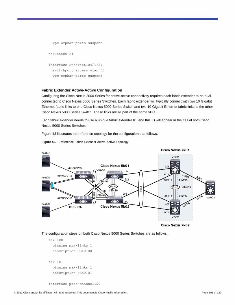
© 2012 Cisco and/or its affiliates. All rights reserved. This document is Cisco Public Information. Page 101 of 120
vpc orphan-ports suspend
nexus5500-2#
interface Ethernet104/1/21
switchport access vlan 50
vpc orphan-ports suspend
Fabric Extender Active-Active Configuration
Configuring the Cisco Nexus 2000 Series for active-active connectivity requires each fabric extender to be dual-
connected to Cisco Nexus 5000 Series Switches. Each fabric extender will typically connect with two 10 Gigabit
Ethernet fabric links to one Cisco Nexus 5000 Series Switch and two 10 Gigabit Ethernet fabric links to the other
Cisco Nexus 5000 Series Switch. These links are all part of the same vPC.
Each fabric extender needs to use a unique fabric extender ID, and this ID will appear in the CLI of both Cisco
Nexus 5000 Series Switches.
Figure 43 illustrates the reference topology for the configuration that follows.
Figure 43. Reference Fabric Extender Active-Active Topology
The configuration steps on both Cisco Nexus 5000 Series Switches are as follows:
fex 100
pinning max-links 1
description FEX0100
fex 101
pinning max-links 1
description FEX0101
interface port-channel100
© 2012 Cisco and/or its affiliates. All rights reserved. This document is Cisco Public Information. Page 102 of 120
switchport mode fex-fabric
vpc 100
fex associate 100
interface port-channel101
switchport mode fex-fabric
vpc 101
fex associate 101
The fabric links connecting to fabric extender 100 would be configured as follows on both Cisco Nexus 5000 Series
Switches:
interface Ethernet1/37
description to_n2k01
switchport mode fex-fabric
fex associate 100
channel-group 100
interface Ethernet1/38
description to_n2k01
switchport mode fex-fabric
fex associate 100
channel-group 100
The fabric links connecting to fabric extender 101 would be configured as follows on both Cisco Nexus 5000 Series
Switches:
interface Ethernet1/39
description to_n2k02
switchport mode fex-fabric
fex associate 101
channel-group 101
interface Ethernet1/40
description to_n2k02
switchport mode fex-fabric
fex associate 101
channel-group 101
The host interfaces must be configured identically on both Cisco Nexus 5000 Series Switches, as in this example:
interface Ethernet101/1/35
switchport mode access
spanning-tree port type edge
© 2012 Cisco and/or its affiliates. All rights reserved. This document is Cisco Public Information. Page 103 of 120
Note that both Cisco Nexus 5000 Series Switches can see every host interface on any fabric extender, and that
they view these single HIFs as if they belonged to a PortChannel; in fact, the configuration on both Cisco Nexus
5000 Series Switches must match. Configurations that do not match for the same host port result in a vPC
inconsistency.
If an interface is not active, the configurations may not be matched, as in this example:
tc-nexus5k01# show int eth100/1/35
Ethernet100/1/35 is down (inactive)
tc-nexus5k01# show vpc consistency-parameters int eth100/1/35
Legend:
Type 1 : vPC will be suspended in case of mismatch
Name Type Local Value Peer Value
------------- ---- ---------------------- -----------------------
Speed 1 1000 Mb/s 1000 Mb/s
Duplex 1 full full
Port Mode 1 access trunk
Shut Lan 1 No No
Allowed VLANs - 50 23-24,30,50,60
If you are using the Cisco Nexus 2248TP or 2232PP, you can also configure fabric extender active-active HIF ports
in PortChannel mode as follows:
interface Ethernet101/1/35 - 36
description tc-esx07
switchport mode access
spanning-tree port type edge
channel-group 7 mode active
vPC Host PortChannels with Fabric Extender Active-Active Topology
On both Cisco Nexus 5000 Series Switches, you need to configure the same PortChannel, but you do not need to
define this as a vPC, as shown in Figure 44:
Nexus 5k01:
interface eth100/1/1-2
channel-group 1001
interface eth101/1/1-2
channel-group 1001
interface port-channel 1001
<other po configs>
Nexus 5k02:
interface eth100/1/1-2
channel-group 1001
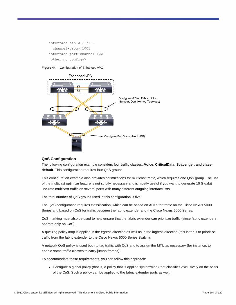
© 2012 Cisco and/or its affiliates. All rights reserved. This document is Cisco Public Information. Page 104 of 120
interface eth101/1/1-2
channel-group 1001
interface port-channel 1001
<other po configs>
Figure 44. Configuration of Enhanced vPC
QoS Configuration
The following configuration example considers four traffic classes: Voice, CriticalData, Scavenger, and class-
default. This configuration requires four QoS groups.
This configuration example also provides optimizations for multicast traffic, which requires one QoS group. The use
of the multicast optimize feature is not strictly necessary and is mostly useful if you want to generate 10 Gigabit
line-rate multicast traffic on several ports with many different outgoing interface lists.
The total number of QoS groups used in this configuration is five.
The QoS configuration requires classification, which can be based on ACLs for traffic on the Cisco Nexus 5000
Series and based on CoS for traffic between the fabric extender and the Cisco Nexus 5000 Series.
CoS marking must also be used to help ensure that the fabric extender can prioritize traffic (since fabric extenders
operate only on CoS).
A queuing policy map is applied in the egress direction as well as in the ingress direction (this latter is to prioritize
traffic from the fabric extender to the Cisco Nexus 5000 Series Switch).
A network QoS policy is used both to tag traffic with CoS and to assign the MTU as necessary (for instance, to
enable some traffic classes to carry jumbo frames).
To accommodate these requirements, you can follow this approach:
● Configure a global policy (that is, a policy that is applied systemwide) that classifies exclusively on the basis
of the CoS. Such a policy can be applied to the fabric extender ports as well.
© 2012 Cisco and/or its affiliates. All rights reserved. This document is Cisco Public Information. Page 105 of 120
● Configure a per-interface policy that classifies on the basis of ACLs. This policy can be applied to Cisco
Nexus 5000 Series ports, including the fabric extender fabric ports, so that traffic can be reclassified based
on ACLs when it reaches the Cisco Nexus 5000 Series Switch.
class-map type qos voice-global
match cos 5
class-map type qos critical-global
match cos 6
class-map type qos scavenger-global
match cos 1
policy-map type qos classify-5000-global
class voice-global
set qos-group 5
class critical-global
set qos-group 3
class scavenger-global
set qos-group 4
You cannot configure class-default, but you should know that the policy map is completed by this default
statement:
class type qos class-default
set qos-group 0
Configure fabric extender ports with the default CoS based on the traffic that the server sends untagged. The traffic
that the server sends tagged with CoS is matched by the classify-5000-global policy applied at the system level.
interface eth103/1/21
untagged cos 6
Repeat the preceding configuration for all the fabric extender ports that require it.
For the Cisco Nexus 5000 Series ports, since you can classify with ACL, you define the equivalent policy that
matches on DSCPs or ACLs as follows:
class-map type qos match-any Voice
match dscp 40,46
class-map type qos Scavenger
match dscp 8
class-map type qos CriticalData
match dscp 18
policy-map type qos classify-per-port
class type qos class-ip-multicast
set qos-group 2
class type qos Voice
set qos-group 5
class type qos CriticalData
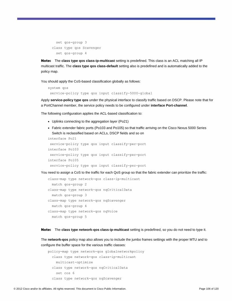
© 2012 Cisco and/or its affiliates. All rights reserved. This document is Cisco Public Information. Page 106 of 120
set qos-group 3
class type qos Scavenger
set qos-group 4
Note: The class type qos class-ip-multicast setting is predefined. This class is an ACL matching all IP
multicast traffic. The class type qos class-default setting also is predefined and is automatically added to the
policy map.
You should apply the CoS-based classification globally as follows:
system qos
service-policy type qos input classify-5000-global
Apply service-policy type qos under the physical interface to classify traffic based on DSCP. Please note that for
a PortChannel member, the service policy needs to be configured under interface Port-channel.
The following configuration applies the ACL-based classification to:
● Uplinks connecting to the aggregation layer (Po21)
● Fabric extender fabric ports (Po103 and Po105) so that traffic arriving on the Cisco Nexus 5000 Series
Switch is reclassified based on ACLs, DSCP fields and so on
interface Po21
service-policy type qos input classify-per-port
interface Po103
service-policy type qos input classify-per-port
interface Po105
service-policy type qos input classify-per-port
You need to assign a CoS to the traffic for each QoS group so that the fabric extender can prioritize the traffic:
class-map type network-qos class-ip-multicast
match qos-group 2
class-map type network-qos nqCriticalData
match qos-group 3
class-map type network-qos nqScavenger
match qos-group 4
class-map type network-qos nqVoice
match qos-group 5
Note: The class type network-qos class-ip-multicast setting is predefined, so you do not need to type it.
The network-qos policy map also allows you to include the jumbo frames settings with the proper MTU and to
configure the buffer space for the various traffic classes:
policy-map type network-qos globalnetworkpolicy
class type network-qos class-ip-multicast
multicast-optimize
class type network-qos nqCriticalData
set cos 6
class type network-qos nqScavenger
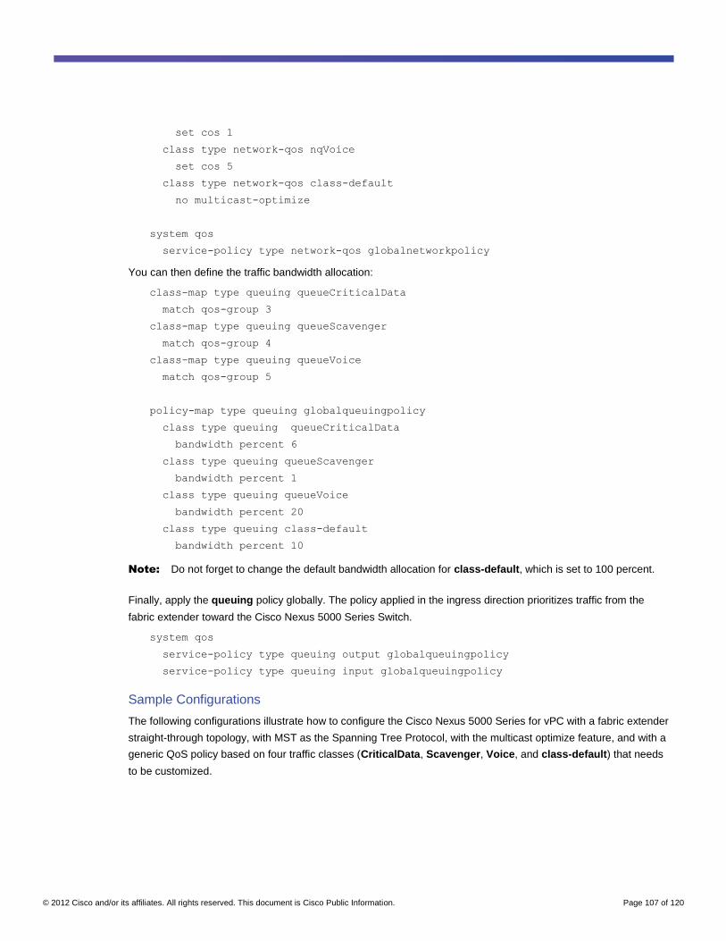
© 2012 Cisco and/or its affiliates. All rights reserved. This document is Cisco Public Information. Page 107 of 120
set cos 1
class type network-qos nqVoice
set cos 5
class type network-qos class-default
no multicast-optimize
system qos
service-policy type network-qos globalnetworkpolicy
You can then define the traffic bandwidth allocation:
class-map type queuing queueCriticalData
match qos-group 3
class-map type queuing queueScavenger
match qos-group 4
class-map type queuing queueVoice
match qos-group 5
policy-map type queuing globalqueuingpolicy
class type queuing queueCriticalData
bandwidth percent 6
class type queuing queueScavenger
bandwidth percent 1
class type queuing queueVoice
bandwidth percent 20
class type queuing class-default
bandwidth percent 10
Note: Do not forget to change the default bandwidth allocation for class-default, which is set to 100 percent.
Finally, apply the queuing policy globally. The policy applied in the ingress direction prioritizes traffic from the
fabric extender toward the Cisco Nexus 5000 Series Switch.
system qos
service-policy type queuing output globalqueuingpolicy
service-policy type queuing input globalqueuingpolicy
Sample Configurations
The following configurations illustrate how to configure the Cisco Nexus 5000 Series for vPC with a fabric extender
straight-through topology, with MST as the Spanning Tree Protocol, with the multicast optimize feature, and with a
generic QoS policy based on four traffic classes (CriticalData, Scavenger, Voice, and class-default) that needs
to be customized.
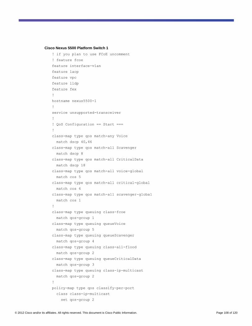
© 2012 Cisco and/or its affiliates. All rights reserved. This document is Cisco Public Information. Page 108 of 120
Cisco Nexus 5500 Platform Switch 1
! if you plan to use FCoE uncomment
! feature fcoe
feature interface-vlan
feature lacp
feature vpc
feature lldp
feature fex
!
hostname nexus5500-1
!
service unsupported-transceiver
!
! QoS Configuration == Start ===
!
class-map type qos match-any Voice
match dscp 40,46
class-map type qos match-all Scavenger
match dscp 8
class-map type qos match-all CriticalData
match dscp 18
class-map type qos match-all voice-global
match cos 5
class-map type qos match-all critical-global
match cos 6
class-map type qos match-all scavenger-global
match cos 1
!
class-map type queuing class-fcoe
match qos-group 1
class-map type queuing queueVoice
match qos-group 5
class-map type queuing queueScavenger
match qos-group 4
class-map type queuing class-all-flood
match qos-group 2
class-map type queuing queueCriticalData
match qos-group 3
class-map type queuing class-ip-multicast
match qos-group 2
!
policy-map type qos classify-per-port
class class-ip-multicast
set qos-group 2
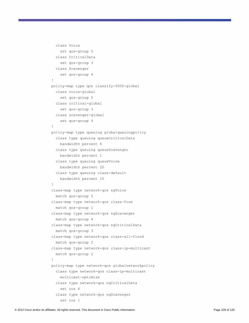
© 2012 Cisco and/or its affiliates. All rights reserved. This document is Cisco Public Information. Page 109 of 120
class Voice
set qos-group 5
class CriticalData
set qos-group 3
class Scavenger
set qos-group 4
!
policy-map type qos classify-5000-global
class voice-global
set qos-group 5
class critical-global
set qos-group 3
class scavenger-global
set qos-group 4
!
policy-map type queuing globalqueuingpolicy
class type queuing queueCriticalData
bandwidth percent 6
class type queuing queueScavenger
bandwidth percent 1
class type queuing queueVoice
bandwidth percent 20
class type queuing class-default
bandwidth percent 10
!
class-map type network-qos nqVoice
match qos-group 5
class-map type network-qos class-fcoe
match qos-group 1
class-map type network-qos nqScavenger
match qos-group 4
class-map type network-qos nqCriticalData
match qos-group 3
class-map type network-qos class-all-flood
match qos-group 2
class-map type network-qos class-ip-multicast
match qos-group 2
!
policy-map type network-qos globalnetworkpolicy
class type network-qos class-ip-multicast
multicast-optimize
class type network-qos nqCriticalData
set cos 6
class type network-qos nqScavenger
set cos 1
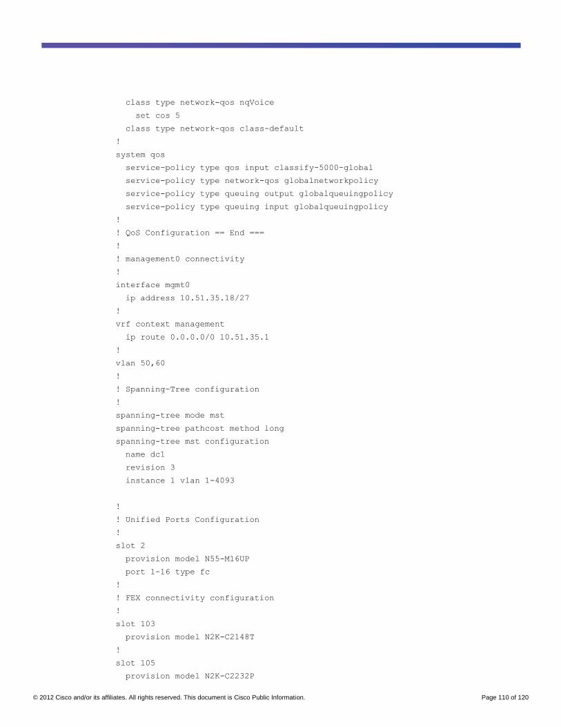
© 2012 Cisco and/or its affiliates. All rights reserved. This document is Cisco Public Information. Page 110 of 120
class type network-qos nqVoice
set cos 5
class type network-qos class-default
!
system qos
service-policy type qos input classify-5000-global
service-policy type network-qos globalnetworkpolicy
service-policy type queuing output globalqueuingpolicy
service-policy type queuing input globalqueuingpolicy
!
! QoS Configuration == End ===
!
! management0 connectivity
!
interface mgmt0
ip address 10.51.35.18/27
!
vrf context management
ip route 0.0.0.0/0 10.51.35.1
!
vlan 50,60
!
! Spanning-Tree configuration
!
spanning-tree mode mst
spanning-tree pathcost method long
spanning-tree mst configuration
name dc1
revision 3
instance 1 vlan 1-4093
!
! Unified Ports Configuration
!
slot 2
provision model N55-M16UP
port 1-16 type fc
!
! FEX connectivity configuration
!
slot 103
provision model N2K-C2148T
!
slot 105
provision model N2K-C2232P
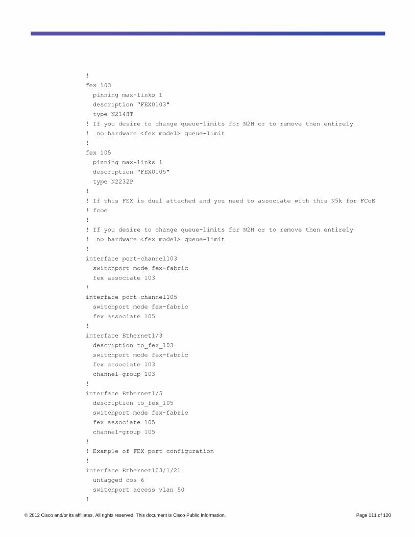
© 2012 Cisco and/or its affiliates. All rights reserved. This document is Cisco Public Information. Page 111 of 120
!
fex 103
pinning max-links 1
description "FEX0103"
type N2148T
! If you desire to change queue-limits for N2H or to remove then entirely
! no hardware <fex model> queue-limit
!
fex 105
pinning max-links 1
description "FEX0105"
type N2232P
!
! If this FEX is dual attached and you need to associate with this N5k for FCoE
! fcoe
!
! If you desire to change queue-limits for N2H or to remove then entirely
! no hardware <fex model> queue-limit
!
interface port-channel103
switchport mode fex-fabric
fex associate 103
!
interface port-channel105
switchport mode fex-fabric
fex associate 105
!
interface Ethernet1/3
description to_fex_103
switchport mode fex-fabric
fex associate 103
channel-group 103
!
interface Ethernet1/5
description to_fex_105
switchport mode fex-fabric
fex associate 105
channel-group 105
!
! Example of FEX port configuration
!
interface Ethernet103/1/21
untagged cos 6
switchport access vlan 50
!
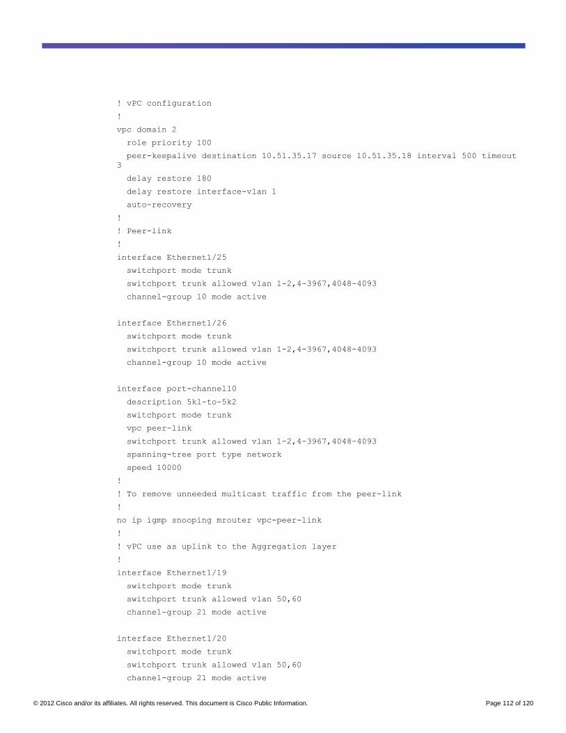
© 2012 Cisco and/or its affiliates. All rights reserved. This document is Cisco Public Information. Page 112 of 120
! vPC configuration
!
vpc domain 2
role priority 100
peer-keepalive destination 10.51.35.17 source 10.51.35.18 interval 500 timeout
3
delay restore 180
delay restore interface-vlan 1
auto-recovery
!
! Peer-link
!
interface Ethernet1/25
switchport mode trunk
switchport trunk allowed vlan 1-2,4-3967,4048-4093
channel-group 10 mode active
interface Ethernet1/26
switchport mode trunk
switchport trunk allowed vlan 1-2,4-3967,4048-4093
channel-group 10 mode active
interface port-channel10
description 5k1-to-5k2
switchport mode trunk
vpc peer-link
switchport trunk allowed vlan 1-2,4-3967,4048-4093
spanning-tree port type network
speed 10000
!
! To remove unneeded multicast traffic from the peer-link
!
no ip igmp snooping mrouter vpc-peer-link
!
! vPC use as uplink to the Aggregation layer
!
interface Ethernet1/19
switchport mode trunk
switchport trunk allowed vlan 50,60
channel-group 21 mode active
interface Ethernet1/20
switchport mode trunk
switchport trunk allowed vlan 50,60
channel-group 21 mode active
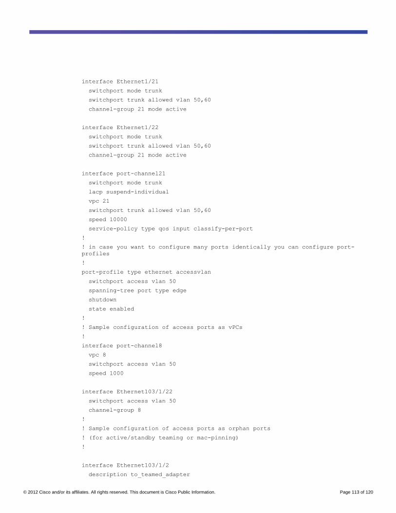
© 2012 Cisco and/or its affiliates. All rights reserved. This document is Cisco Public Information. Page 113 of 120
interface Ethernet1/21
switchport mode trunk
switchport trunk allowed vlan 50,60
channel-group 21 mode active
interface Ethernet1/22
switchport mode trunk
switchport trunk allowed vlan 50,60
channel-group 21 mode active
interface port-channel21
switchport mode trunk
lacp suspend-individual
vpc 21
switchport trunk allowed vlan 50,60
speed 10000
service-policy type qos input classify-per-port
!
! in case you want to configure many ports identically you can configure port-
profiles
!
port-profile type ethernet accessvlan
switchport access vlan 50
spanning-tree port type edge
shutdown
state enabled
!
! Sample configuration of access ports as vPCs
!
interface port-channel8
vpc 8
switchport access vlan 50
speed 1000
interface Ethernet103/1/22
switchport access vlan 50
channel-group 8
!
! Sample configuration of access ports as orphan ports
! (for active/standby teaming or mac-pinning)
!
interface Ethernet103/1/2
description to_teamed_adapter
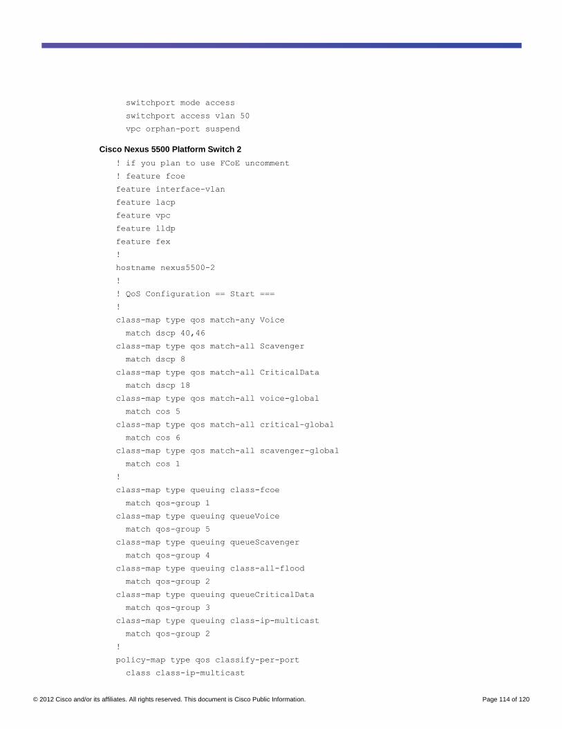
© 2012 Cisco and/or its affiliates. All rights reserved. This document is Cisco Public Information. Page 114 of 120
switchport mode access
switchport access vlan 50
vpc orphan-port suspend
Cisco Nexus 5500 Platform Switch 2
! if you plan to use FCoE uncomment
! feature fcoe
feature interface-vlan
feature lacp
feature vpc
feature lldp
feature fex
!
hostname nexus5500-2
!
! QoS Configuration == Start ===
!
class-map type qos match-any Voice
match dscp 40,46
class-map type qos match-all Scavenger
match dscp 8
class-map type qos match-all CriticalData
match dscp 18
class-map type qos match-all voice-global
match cos 5
class-map type qos match-all critical-global
match cos 6
class-map type qos match-all scavenger-global
match cos 1
!
class-map type queuing class-fcoe
match qos-group 1
class-map type queuing queueVoice
match qos-group 5
class-map type queuing queueScavenger
match qos-group 4
class-map type queuing class-all-flood
match qos-group 2
class-map type queuing queueCriticalData
match qos-group 3
class-map type queuing class-ip-multicast
match qos-group 2
!
policy-map type qos classify-per-port
class class-ip-multicast
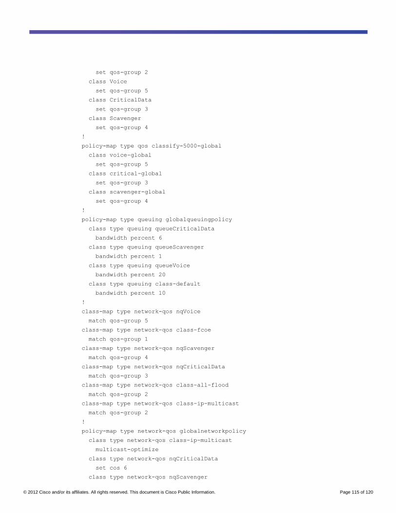
© 2012 Cisco and/or its affiliates. All rights reserved. This document is Cisco Public Information. Page 115 of 120
set qos-group 2
class Voice
set qos-group 5
class CriticalData
set qos-group 3
class Scavenger
set qos-group 4
!
policy-map type qos classify-5000-global
class voice-global
set qos-group 5
class critical-global
set qos-group 3
class scavenger-global
set qos-group 4
!
policy-map type queuing globalqueuingpolicy
class type queuing queueCriticalData
bandwidth percent 6
class type queuing queueScavenger
bandwidth percent 1
class type queuing queueVoice
bandwidth percent 20
class type queuing class-default
bandwidth percent 10
!
class-map type network-qos nqVoice
match qos-group 5
class-map type network-qos class-fcoe
match qos-group 1
class-map type network-qos nqScavenger
match qos-group 4
class-map type network-qos nqCriticalData
match qos-group 3
class-map type network-qos class-all-flood
match qos-group 2
class-map type network-qos class-ip-multicast
match qos-group 2
!
policy-map type network-qos globalnetworkpolicy
class type network-qos class-ip-multicast
multicast-optimize
class type network-qos nqCriticalData
set cos 6
class type network-qos nqScavenger
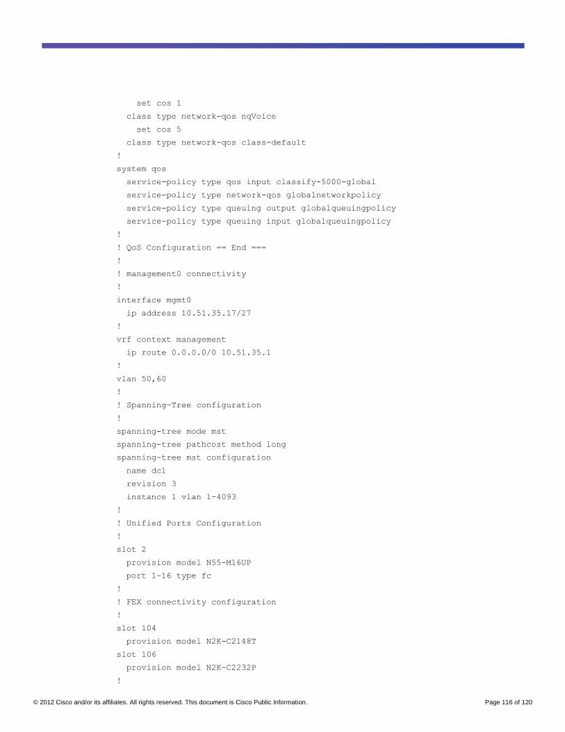
© 2012 Cisco and/or its affiliates. All rights reserved. This document is Cisco Public Information. Page 116 of 120
set cos 1
class type network-qos nqVoice
set cos 5
class type network-qos class-default
!
system qos
service-policy type qos input classify-5000-global
service-policy type network-qos globalnetworkpolicy
service-policy type queuing output globalqueuingpolicy
service-policy type queuing input globalqueuingpolicy
!
! QoS Configuration == End ===
!
! management0 connectivity
!
interface mgmt0
ip address 10.51.35.17/27
!
vrf context management
ip route 0.0.0.0/0 10.51.35.1
!
vlan 50,60
!
! Spanning-Tree configuration
!
spanning-tree mode mst
spanning-tree pathcost method long
spanning-tree mst configuration
name dc1
revision 3
instance 1 vlan 1-4093
!
! Unified Ports Configuration
!
slot 2
provision model N55-M16UP
port 1-16 type fc
!
! FEX connectivity configuration
!
slot 104
provision model N2K-C2148T
slot 106
provision model N2K-C2232P
!
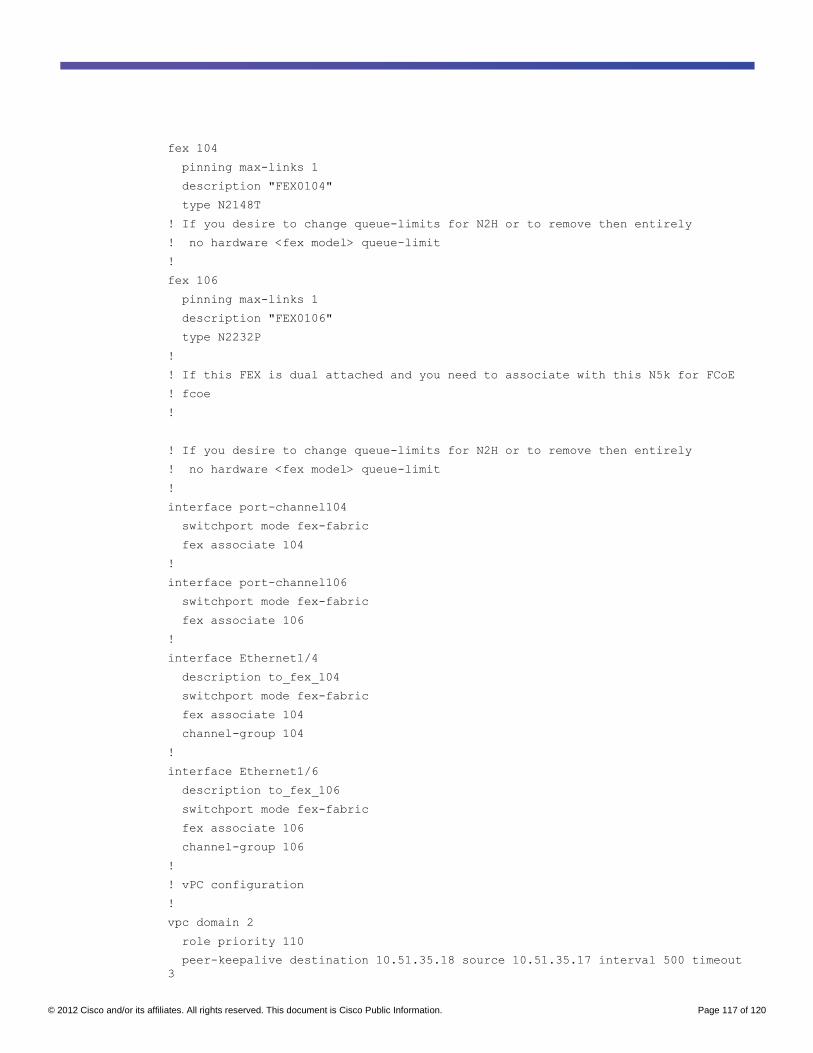
© 2012 Cisco and/or its affiliates. All rights reserved. This document is Cisco Public Information. Page 117 of 120
fex 104
pinning max-links 1
description "FEX0104"
type N2148T
! If you desire to change queue-limits for N2H or to remove then entirely
! no hardware <fex model> queue-limit
!
fex 106
pinning max-links 1
description "FEX0106"
type N2232P
!
! If this FEX is dual attached and you need to associate with this N5k for FCoE
! fcoe
!
! If you desire to change queue-limits for N2H or to remove then entirely
! no hardware <fex model> queue-limit
!
interface port-channel104
switchport mode fex-fabric
fex associate 104
!
interface port-channel106
switchport mode fex-fabric
fex associate 106
!
interface Ethernet1/4
description to_fex_104
switchport mode fex-fabric
fex associate 104
channel-group 104
!
interface Ethernet1/6
description to_fex_106
switchport mode fex-fabric
fex associate 106
channel-group 106
!
! vPC configuration
!
vpc domain 2
role priority 110
peer-keepalive destination 10.51.35.18 source 10.51.35.17 interval 500 timeout
3
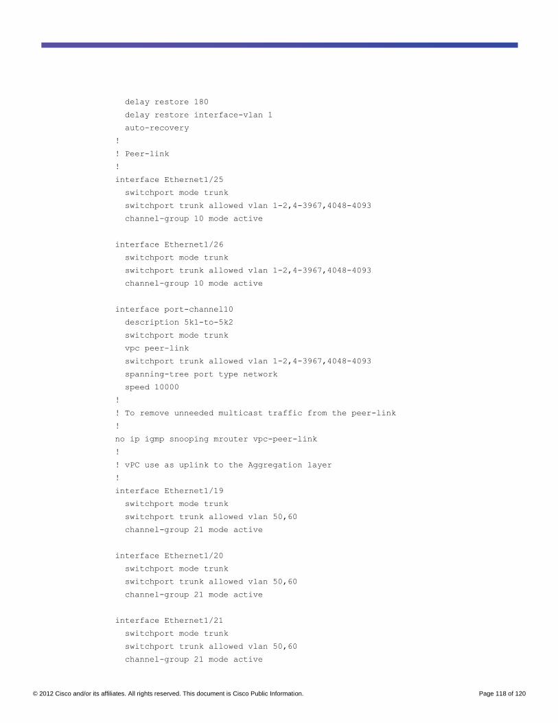
© 2012 Cisco and/or its affiliates. All rights reserved. This document is Cisco Public Information. Page 118 of 120
delay restore 180
delay restore interface-vlan 1
auto-recovery
!
! Peer-link
!
interface Ethernet1/25
switchport mode trunk
switchport trunk allowed vlan 1-2,4-3967,4048-4093
channel-group 10 mode active
interface Ethernet1/26
switchport mode trunk
switchport trunk allowed vlan 1-2,4-3967,4048-4093
channel-group 10 mode active
interface port-channel10
description 5k1-to-5k2
switchport mode trunk
vpc peer-link
switchport trunk allowed vlan 1-2,4-3967,4048-4093
spanning-tree port type network
speed 10000
!
! To remove unneeded multicast traffic from the peer-link
!
no ip igmp snooping mrouter vpc-peer-link
!
! vPC use as uplink to the Aggregation layer
!
interface Ethernet1/19
switchport mode trunk
switchport trunk allowed vlan 50,60
channel-group 21 mode active
interface Ethernet1/20
switchport mode trunk
switchport trunk allowed vlan 50,60
channel-group 21 mode active
interface Ethernet1/21
switchport mode trunk
switchport trunk allowed vlan 50,60
channel-group 21 mode active
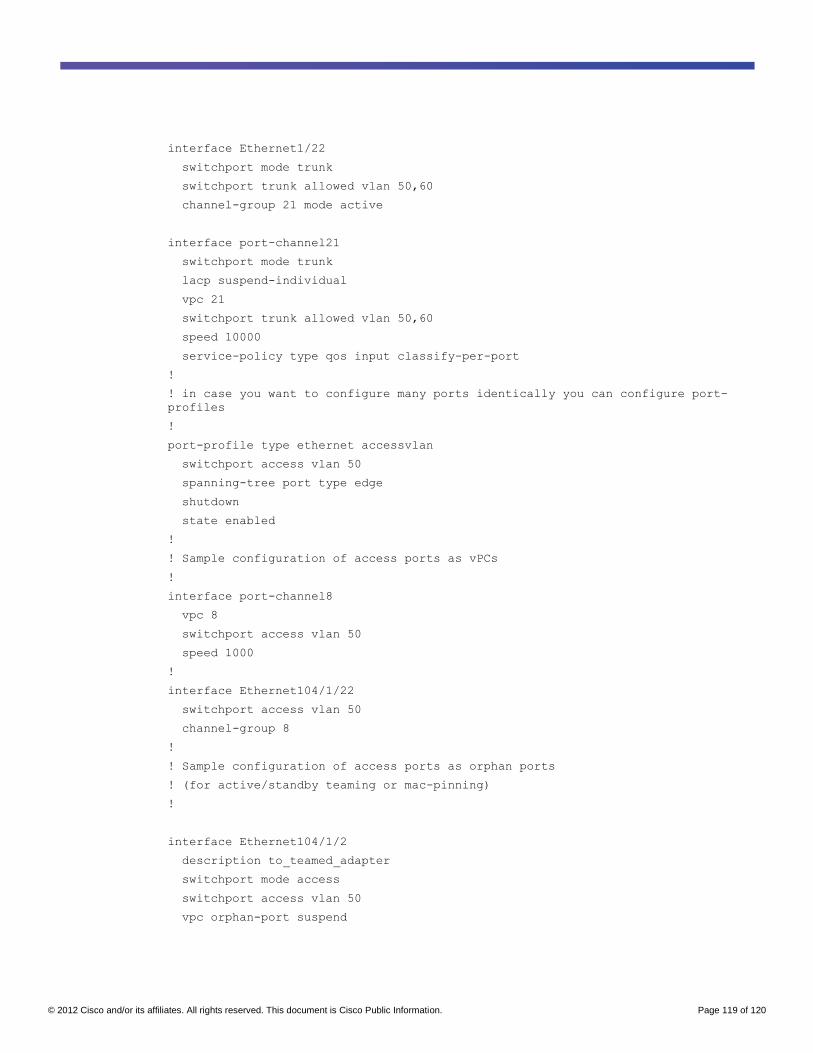
© 2012 Cisco and/or its affiliates. All rights reserved. This document is Cisco Public Information. Page 119 of 120
interface Ethernet1/22
switchport mode trunk
switchport trunk allowed vlan 50,60
channel-group 21 mode active
interface port-channel21
switchport mode trunk
lacp suspend-individual
vpc 21
switchport trunk allowed vlan 50,60
speed 10000
service-policy type qos input classify-per-port
!
! in case you want to configure many ports identically you can configure port-
profiles
!
port-profile type ethernet accessvlan
switchport access vlan 50
spanning-tree port type edge
shutdown
state enabled
!
! Sample configuration of access ports as vPCs
!
interface port-channel8
vpc 8
switchport access vlan 50
speed 1000
!
interface Ethernet104/1/22
switchport access vlan 50
channel-group 8
!
! Sample configuration of access ports as orphan ports
! (for active/standby teaming or mac-pinning)
!
interface Ethernet104/1/2
description to_teamed_adapter
switchport mode access
switchport access vlan 50
vpc orphan-port suspend

© 2012 Cisco and/or its affiliates. All rights reserved. This document is Cisco Public Information. Page 120 of 120
Printed in USA C07-572829-05 10/12