Embed Size (px)
Citation preview
Data Center Network Topologies II
Hakim WeatherspoonAssociate Professor, Dept of Computer Science
CS 5413: High Performance Systems and NetworkingApril 10, 2017 March 31, 2017
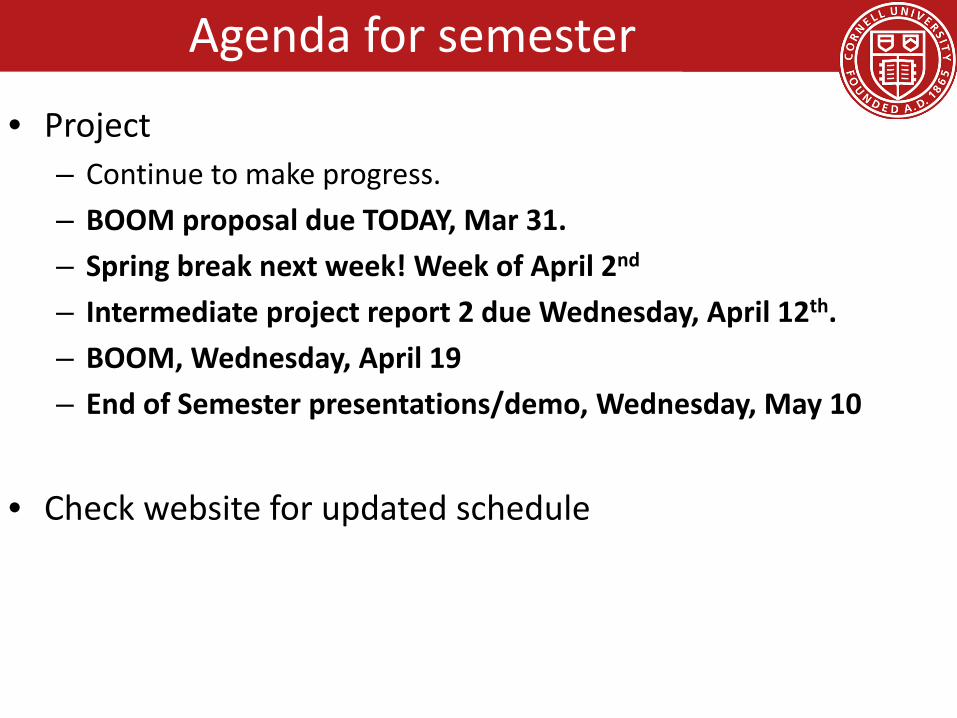
Agenda for semester
• Project– Continue to make progress.– BOOM proposal due TODAY, Mar 31.– Spring break next week! Week of April 2nd
– Intermediate project report 2 due Wednesday, April 12th.– BOOM, Wednesday, April 19– End of Semester presentations/demo, Wednesday, May 10
• Check website for updated schedule
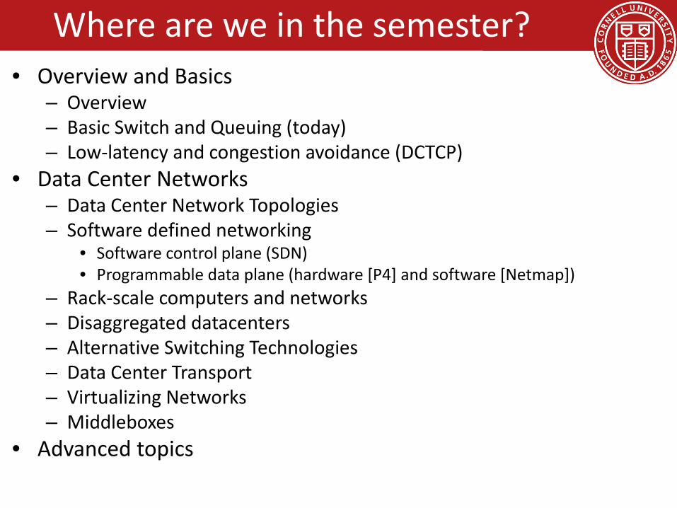
• Overview and Basics– Overview– Basic Switch and Queuing (today)– Low-latency and congestion avoidance (DCTCP)
• Data Center Networks– Data Center Network Topologies– Software defined networking
• Software control plane (SDN)• Programmable data plane (hardware [P4] and software [Netmap])
– Rack-scale computers and networks– Disaggregated datacenters– Alternative Switching Technologies– Data Center Transport– Virtualizing Networks– Middleboxes
• Advanced topics
Where are we in the semester?

• Interested Topics:– SDN and programmable data planes– Disaggregated datacenters and rack-scale
computers– Alternative switch technologies– Datacenter topologies– Datacenter transports– Advanced topics
4
Where are we in the semester?

Architecture of Data Center Networks (DCN)
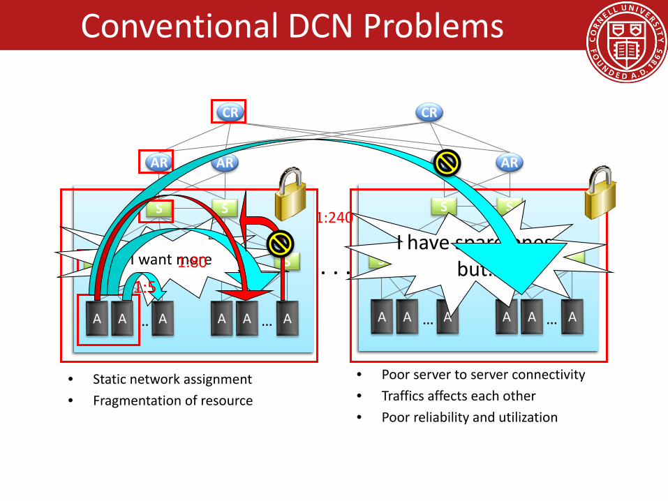
Conventional DCN Problems
• Static network assignment• Fragmentation of resource
• Poor server to server connectivity• Traffics affects each other• Poor reliability and utilization
CR CR
AR AR AR AR
SS
SS
…
SS
…
. . .
SS
SS
…
SS
…
I want moreI have spare ones,
but…1:5
1:80
1:240

Objectives:• Uniform high capacity:
– Maximum rate of server to server traffic flow should be limited only by capacity on network cards
– Assigning servers to service should be independent of network topology
• Performance isolation:– Traffic of one service should not be affected by traffic of other
services
• Layer-2 semantics:– Easily assign any server to any service– Configure server with whatever IP address the service expects– VM keeps the same IP address even after migration
Discuss Today

8
1. L2 semantics
2. Uniform high capacity
3. Performance isolation
… …
. . .
… …
CR CR
AR AR AR AR
SS
SS SS
SS
SS SS
. . .
Virtual Layer 2 Switch (VL2)
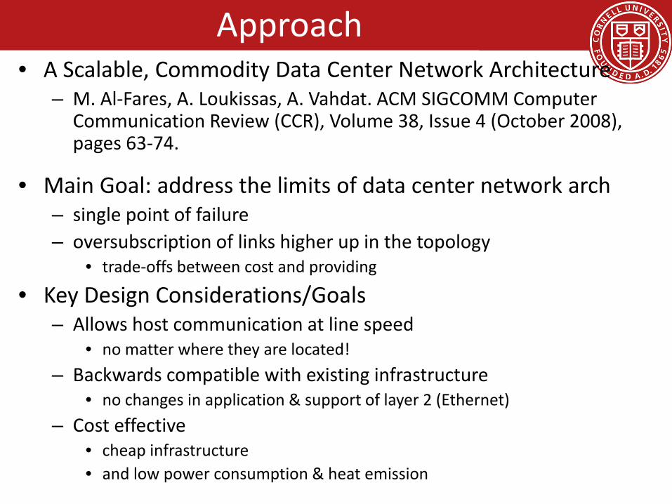
Approach• A Scalable, Commodity Data Center Network Architecture
– M. Al-Fares, A. Loukissas, A. Vahdat. ACM SIGCOMM Computer Communication Review (CCR), Volume 38, Issue 4 (October 2008), pages 63-74.
• Main Goal: address the limits of data center network arch– single point of failure– oversubscription of links higher up in the topology
• trade-offs between cost and providing
• Key Design Considerations/Goals– Allows host communication at line speed
• no matter where they are located!– Backwards compatible with existing infrastructure
• no changes in application & support of layer 2 (Ethernet)– Cost effective
• cheap infrastructure • and low power consumption & heat emission
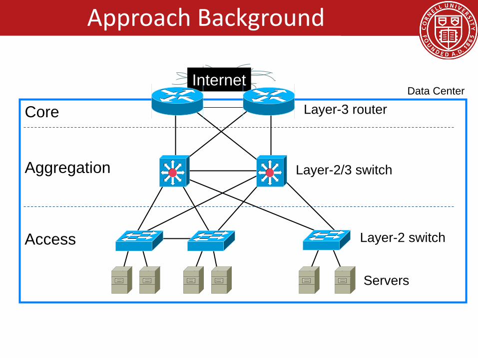
Internet
Servers
Layer-2 switchAccess
Data Center
Layer-2/3 switchAggregation
Layer-3 routerCore
Approach Background

Approach BackgroundOversubscription: Ratio of the worst-case achievable aggregate bandwidth
among the end hosts to the total bisection bandwidth of a particular communication topology
Lower the total cost of the design Typical designs: factor of 2:5:1 (4 Gbps) to 8:1(1.25 Gbps)
Cost: Edge: $7,000 for each 48-port 10 GigE switch Aggregation and core: $700,000 for 64-port 100GigE
switches Cabling costs are not considered!

Properties of the solution• Backwards compatible with existing infrastructure
– No changes in application– Support of layer 2 (Ethernet)
• Cost effective– Low power consumption & heat emission– Cheap infrastructure
• Allows host communication at line speed
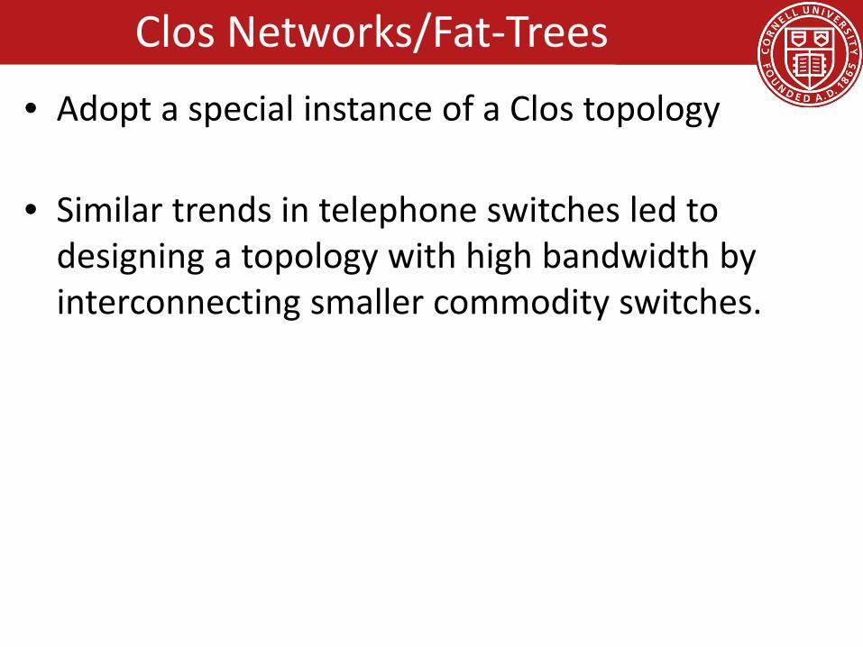
Clos Networks/Fat-Trees• Adopt a special instance of a Clos topology
• Similar trends in telephone switches led to designing a topology with high bandwidth by interconnecting smaller commodity switches.

• Inter-connect racks (of servers) using a fat-tree topologyK-ary fat tree: three-layer topology (edge, aggregation and core)– each pod consists of (k/2)2 servers & 2 layers of k/2 k-port switches– each edge switch connects to k/2 servers & k/2 aggr. switches – each aggr. switch connects to k/2 edge & k/2 core switches– (k/2)2 core switches: each connects to k pods
Fat-tree with K=4
FatTree-based DC Architecture
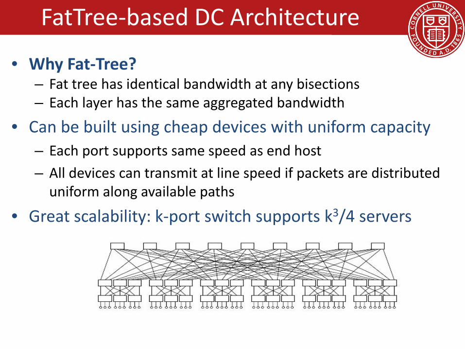
• Why Fat-Tree?– Fat tree has identical bandwidth at any bisections– Each layer has the same aggregated bandwidth
• Can be built using cheap devices with uniform capacity– Each port supports same speed as end host– All devices can transmit at line speed if packets are distributed
uniform along available paths
• Great scalability: k-port switch supports k3/4 servers
Fat tree network with K = 6 supporting 54 hosts
FatTree-based DC Architecture

Clos Network Topology
17
. . .
. . .
TOR
20 Servers
Int
. . . . . . . . .
Aggr
K aggr switches with D ports
20*(DK/4) Servers. . . . . . . . . . .
Offer huge aggr capacity & multi paths at modest cost
D (# of 10G ports)
Max DC size(# of Servers)
48 11,52096 46,080144 103,680

Does using fat-tree topology to inter-connect racks of servers in itself sufficient?
• What routing protocols should we run on these switches?
• Layer 2 switch algorithm: data plane flooding!• Layer 3 IP routing:
– shortest path IP routing will typically use only one path despite the path diversity in the topology
– if using equal-cost multi-path routing at each switch independently and blindly, packet re-ordering may occur; further load may not necessarily be well-balanced
– Aside: control plane flooding!
18
FatTree Topology is great, But…
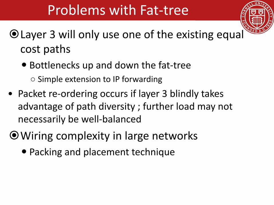
Problems with Fat-treeLayer 3 will only use one of the existing equal
cost paths Bottlenecks up and down the fat-tree○ Simple extension to IP forwarding
• Packet re-ordering occurs if layer 3 blindly takes advantage of path diversity ; further load may not necessarily be well-balanced
Wiring complexity in large networks Packing and placement technique

Enforce a special (IP) addressing scheme in DC unused.PodNumber.switchnumber.Endhost Allows host attached to same switch to route only
through switch Allows inter-pod traffic to stay within pod
FatTree Modified

Diffusion Optimizations (routing options)
1. Flow classification, Denote a flow as a sequence of packets; pod switches forward subsequent packets of the same flow to same outgoing port. And periodically reassign a minimal number of output ports
Eliminates local congestion Assign traffic to ports on a per-flow basis
instead of a per-host basis, Ensure fair distribution on flows
FatTree Modified

2. Flow scheduling, Pay attention to routing large flows, edge switches detect any outgoing flow whose size grows above a predefined threshold, and then send notification to a central scheduler. The central scheduler tries to assign non-conflicting paths for these large flows.
– Eliminates global congestion– Prevent long lived flows from sharing the same links– Assign long lived flows to different links
FatTree Modified
• In this scheme, each switch in the network maintains a BFD (Bidirectional Forwarding Detection) session with each of its neighbors to determine when a link or neighboring switch fails
Failure between upper layer and core switches Outgoing inter-pod traffic, local routing table marks the
affected link as unavailable and chooses another core switch
Incoming inter-pod traffic, core switch broadcasts a tag to upper switches directly connected signifying its inability to carry traffic to that entire pod, then upper switches avoid that core switch when assigning flows destined to that pod
Fault Tolerance
• Failure between lower and upper layer switches– Outgoing inter- and intra pod traffic from lower-layer,
– the local flow classifier sets the cost to infinity and does not assign it any new flows, chooses another upper layer switch
– Intra-pod traffic using upper layer switch as intermediary– Switch broadcasts a tag notifying all lower level
switches, these would check when assigning new flows and avoid it
– Inter-pod traffic coming into upper layer switch– Tag to all its core switches signifying its ability to carry
traffic, core switches mirror this tag to all upper layer switches, then upper switches avoid affected core switch when assigning new flaws
Fault Tolerance

Packing Increased wiring overhead is inherent to the fat-tree
topologyEach pod consists of 12 racks with 48 machines each,
and 48 individual 48-port GigE switchesPlace the 48 switches in a centralized rackCables moves in sets of 12 from pod to pod and in
sets of 48 from racks to pod switches opens additional opportunities for packing to reduce wiring complexity
Minimize total cable length by placing racks around the pod switch in two dimensions
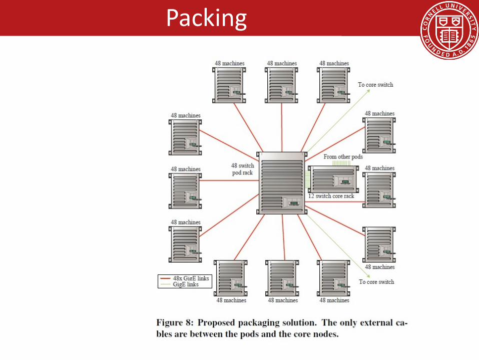
Packing
PerspectiveBandwidth is the scalability bottleneck in large
scale clustersExisting solutions are expensive and limit cluster
sizeFat-tree topology with scalable routing and
backward compatibility with TCP/IP and EthernetLarge number of commodity switches have the
potential of displacing high end switches in DC the same way clusters of commodity PCs have displaced supercomputers for high end computing environments

• A Scalable, Commodity Data Center Network Architecture– a new Fat-tree “inter-connection” structure (topology) to
increases “bi-section” bandwidth • needs “new” addressing, forwarding/routing
• VL2: A Scalable and Flexible Data Center Network– consolidate layer-2/layer-3 into a “virtual layer 2”– separating “naming” and “addressing”, also deal with dynamic
load-balancing issues
Other Approaches:• PortLand: A Scalable Fault-Tolerant Layer 2 Data Center Network
Fabric• BCube: A High-Performance, Server-centric Network Architecture for
Modular Data Centers28
Other Data Center Architectures
Agenda for semester
• Project– Continue to make progress.– BOOM proposal due TODAY, Mar 31.– Spring break next week! Week of April 2nd
– Intermediate project report 2 due Wednesday, April 12th.– BOOM, Wednesday, April 19– End of Semester presentations/demo, Wednesday, May 10
• Check website for updated schedule