Embed Size (px)
Citation preview

Data Center Service Integration: Service Chassis Design Guide
Cisco Validated Design
September 5, 2008
IntroductionThis document provides reference architectures and configuration guidance for the integrating intelligent networking services such as server load balancing and firewall into an enterprise data center. Dedicated Catalyst 6500 Services Chassis housing Firewall Services Modules (FWSM) and Application Control Engine (ACE) service modules are leveraged in the example architecture.
AudienceThis document is intended for network engineers and architects who need to understand the design options and configurations necessary for advanced networking services placed in a dedicated region of the data center network.
Document Objectives
The objective of this document is to provide customers guidance on how to deploy network services in a Cisco data center leveraging a dedicated network services layer. This document is not intended to introduce the reader to basic Cisco data center design best practices, but to build upon these well-documented concepts. The prerequisite Cisco data center design knowledge can be found at the following locations:
• Cisco.com—Data Center:
http://www.cisco.com/go/dc
• Cisco Validated Design (CVD) Program:
http://www.cisco.com/en/US/netsol/ns741/networking_solutions_program_home.html
Americas Headquarters:
© 2008 Cisco Systems, Inc. All rights reserved.
Cisco Systems, Inc., 170 West Tasman Drive, San Jose, CA 95134-1706 USA

OL-17051-01 Overview
Document Format and Naming ConventionsUser-defined properties such as access control list names and policy definitions are shown in ALL CAPS to assist the reader in understanding what is user-definable versus command specific. All commands are shown in Courier font. All commands that are applicable to the section covered will be in BOLD.
OverviewThe data center is a critical portion of the Enterprise network. The data center network design must address the high availability requirements of any device or link failure. It is also an area where more intelligence is required from the network, to perform services such as firewall and the load balancing of servers and the applications they host. This document examines two architecture models for integrating these services into a dedicated pair of Catalyst 6500 Services Chassis within the data center topology.
Service Integration Approaches
Integrated Services Physical Model
The Cisco Catalyst 6500 platform offers the option of integrating service modules directly into card slots within the chassis, conserving valuable rack space, power, and cabling in the data center network. One common design model is to integrate these modules directly into the Aggregation layer switches within the hierarchical network design, as shown in Figure 1. This approach is commonly taken when there are available slots within existing Aggregation layer switches, or chassis slot capacity is planned and allocated to the service modules in the initial design.
2Data Center Service Integration: Service Chassis Design Guide
OL-17051-01

OL-17051-01 Overview
Figure 1 Integrated Services Physical Model
Services Chassis Physical Model
As the data center network grows and needs to scale larger over time, there can be a demand to recover the slots that are being consumed by the service modules to accommodate greater port density in the Aggregation layer. This would allow aggregation of a greater number of Access layer switches without needing to move to a second aggregation block. Other factors may drive the migration away from an integrated services approach, such as the desire to deploy new hardware in the Aggregation layer that may not support the Cisco Catalyst 6500 service modules. For example, the Cisco Nexus 7000 Series switches have a different linecard form factor and do not support Cisco Catalyst 6500 service modules. The initial release of the Cisco Catalyst 6500 Virtual Switching System 1440 does not support installation of service modules in the chassis, this support requires new software that is planned for Cisco IOS Release 12.2(33)SXI .
Since these modules require a Cisco Catalyst 6500 chassis for power and network connectivity, another approach for integrating these devices into the data center network may be considered. One approach is the implementation of an additional pair of Cisco 6500 chassis, adjacent to the Aggregation layer of the data center network. These switches are commonly referred to as Services Chassis.
Data CenterServer Farm
EnterpriseNetwork
Core
Aggregation
Access
2245
95
IntegratedServicesModules
3Data Center Service Integration: Service Chassis Design Guide
OL-17051-01

OL-17051-01 Overview
Figure 2 Services Chassis Physical Model
The Services Chassis Physical model, as shown in Figure 2, uses a dual-homed approach for data path connectivity of the Services Chassis into both of the Aggregation layer switches. This approach decouples the service modules from dependence on a specific aggregation switch. This provides operational flexibility for system maintenance that may be required to the aggregation switches or the services switches. From a high availability perspective, if one of the aggregation switches fails, traffic can continue to flow through the other aggregation switch to the active service modules without any failover event needing to occur with the service modules themselves.
802.1q trunking is used on the dual-homed links to allow common physical links to carry ingress and egress traffic VLANs, as well as VLANs that reside between the layers of service modules which must be extended to provide high availability in the event of device or link failure. A separate physical link is recommended directly between the two Services Chassis to carry fault-tolerance traffic and replicate state information between the active and standby modules. Provisioning this separate link ensures that the fault-tolerance control traffic will not be overrun by user data traffic, removing the need for the use of quality-of-service (QoS) class definitions to protect the fault-tolerance traffic across the Aggregation layer.
Core
Aggregation
Data CenterServer Farm
EnterpriseNetwork
Access
Services
2245
96
ExternalServicesChassis
4Data Center Service Integration: Service Chassis Design Guide
OL-17051-01

OL-17051-01 Overview
Logical Design Options
Once the physical layer connectivity of the Services Chassis is decided, there are still many options to choose from to design the logical topology. Some of these options include:
• Service modules inline or one-armed with traffic redirection?
• Service modules deployed in a routed (Layer 3) or transparent (Layer 2) mode? If routed, use a dynamic routing protocol or static routes?
• Employing non-virtualized or single-context service modules or multiple virtual contexts for services?
• Server farm subnets default gateway placement on a service module or on a router?
• Use global MSFC routing only or include Virtual Routing Forwarding-lite? (VRF-lite)?
Add to these questions the application-specific requirements and addressing constraints of a particular customer’s existing network design. Designing services into the data center network may become a complex project to undertake for the network architect. In order to simplify this process, Cisco Enterprise Solutions Engineering (ESE) has validated two reference architectures for the integration of Services Chassis into the Enterprise data center network.
Logical Design Goals
Network design can often include tradeoffs when choosing between design options, there are always pros and cons involved. Cisco ESE pursued the following goals in the development of Services Chassis reference architectures for validation:
Seamless Service Integration
Provide for the insertion or removal of services into a chain for a specific class of server with the least amount of reconfiguration required.
Architecture Flexibility
Design models that can remain consistent in terms of connectivity requirements and flows, even if a specific module is run in a different mode, or a newer product is inserted into the same role at a future time.
Predictable Traffic Patterns
The design should optimize traffic paths first for the normal running state with all devices in place. Failover patterns should be optimized if possible but not at the expense of the normal state.
Consistent Network Reconvergence Times
A full high availability analysis was conducted on the reference models as part of the design validation process. This included simulated failure of each link or device in the primary traffic path, with an analysis of reconvergence times and failover traffic paths.
5Data Center Service Integration: Service Chassis Design Guide
OL-17051-01

OL-17051-01 Overview
Focus on Frontend Services Between Client and Server
Customer data centers may contain multi-tier applications and specific requirements such as servers that require Layer 2 adjacency with services between the servers. These requirements can significantly impact design decisions. The validation of these reference models for Services Chassis integration was focused primarily at client to server interaction.
Focus on the Most Common Data Center Services Being Deployed in the Enterprise
In surveys of Enterprise customers, Firewall and Server Load Balancing were the most common services being deployed in the data center. The Cisco Firewall Services Module (FWSM) and Application Control Engine Module (ACE) were chosen to represent these classes of services.
As a product of these design options and goals, two primary data center Services Chassis logical reference architectures have been validated. The first model is a simple Active-Standby architecture with no virtualization of services. The second model is a full Active-Active, virtualized architecture with multiple FWSM and ACE contexts, and VRF instances controlling the routing functions for these contexts. The standard physical Services Chassis model shown in Figure 2 above was used for all validation.
Service Chassis Logical Topologies
Active-Standby Service Chassis
The first reference design model discussed is referred to as the Active-Standby Services Chassis model. This model focuses on simplicity of implementation, and builds an intentionally one-sided flow of traffic through the primary active Services Chassis. The secondary Services Chassis and its associated modules act purely as hot standby devices, present for fault tolerance in case the primary chassis or one of the modules fails. An illustration of the traffic flow for the Active-Standby model is provided in Figure 3.
Figure 3 Active-Standby Traffic Flow
Active Chassis 1
Data Center Core
Agg 1
Server Side
Client Side
Active Chassis 2Agg 2
Access/Server Farm
2245
97
6Data Center Service Integration: Service Chassis Design Guide
OL-17051-01

OL-17051-01 Overview
Architecture Attributes
This design model was validated with the following characteristics:
Routed FWSM
A routed service device is conceptually easier to implement and troubleshoot, since there is a one-to-one correlation between VLANs and subnets, and a simplified Spanning Tree structure since the device is not forwarding BPDUs between VLANs.
One-Armed ACE
The one-armed ACE can be introduced seamlessly into the network, and will not be in the path of other traffic that does not need to hit the virtual IP (VIP) addresses. ACE failure or failover only impacts traffic that is being load-balanced or leveraging other ACE application services such as SSL acceleration. A traffic-diversion mechanism is required to ensure both sides of a protocol exchange pass through the ACE, either Policy-Based Routing (PBR) or Source-Address Network Address Translation (Source-NAT) may be used. Source-NAT was chosen for the validation of this design due to ease of configuration and support relative to PBR.
Services Chassis Global MSFC as IP Default Gateway for Server Farm Subnets
Using the MSFC as default gateway for servers provides for the insertion or removal of services above the MSFC without altering the basic IP configuration of devices in the server farm. It also prevents the need to enable ICMP redirects or have load-balanced traffic traverse the FWSM twice during a flow.
Traffic Flow Between Service Modules and Clients
For client/server traffic, ingress and egress traffic on the client side is balanced across both aggregation 6500’s global MSFC’s.
Traffic Flow Between Service Modules and Server Farm
For client/server traffic, ingress and egress traffic on the server (Access layer) side is concentrated in one of the Aggregation layer switches that is configured as the IP default gateway for the server farm subnets.
Note For server-to-server traffic, the traffic would be contained to a given access switch or be forwarded through the Aggregation layer if the servers are Layer 2 adjacent and on the same IP subnet. If the servers are on different subnets, the traffic needs to traverse the Services Chassis to forward between subnets. This model may not be optimal for server-to-server traffic flow between subnets. Consider the Active-Active Services Chassis model, which leverages VRFs in the Aggregation layer to streamline the flow of server-to-server traffic.
A full description of the VLANs, IP Subnets, and features used in the configuration of the Active-Standby design follows in the Active/Standby Service Chassis Design, page 11.
Active-Active Service Chassis
The second reference design model discussed is referred to as the Active-Active Services Chassis model. This model leverages the virtualization capabilities of the FWSM and ACE Modules to distribute a portion of the traffic across both Services Chassis. The traffic is not automatically equally balanced across the devices, but the network administrator has the ability to assign different server farm subnets to specific contexts, which may be done based on expected load or based on other organizational factors. Routing virtualization is also used in the active-active model through the implementation of VRF instances in the aggregation switches. In the validated active-active model, all Layer 3 processing takes
7Data Center Service Integration: Service Chassis Design Guide
OL-17051-01

OL-17051-01 Overview
place in the Aggregation layer, and simplifies the implementation of the Services Chassis by keeping them as pure Layer 2 connected adjunct switches. However, the model is flexible enough to support the implementation of a routed FWSM or ACE if it better supports specific customer requirements. An illustration of the traffic flow for the Active-Standby model as validated is provided in Figure 4.
Figure 4 Active-Active Traffic Flow
Architecture Attributes
This design model was validated with the following characteristics:
Transparent FWSM
A transparent firewall requires less configuration than a routed firewall, since there is no routing protocol to configure or list of static routes to maintain. It requires only a single IP subnet on the bridge-group interface, and forwards BPDUs between bridging devices that live on attached segments, in that way it is truly transparent, and not a bridge itself. The VLANs on the different interfaces of the transparent FWSM will carry different VLAN numbers, so a transparent device is often said to be "stitching" or "chaining" VLANs together.
Note The FWSM supports a maximum of eight bridge-group interfaces (BVI) per context.
Transparent ACE
The transparent ACE implementation works similarly to the FWSM, where multiple VLANs are stitched together to transport one IP subnet, and BPDUs are forwarded to allow adjacent switches to perform Spanning Tree calculations. Unlike the One-Armed ACE approach, a transparent ACE sits inline with traffic, and requires no traffic diversion mechanism to ensure that both sides of a protocol exchange pass through the device. The ACE supports a maximum of two Layer 2 interface VLANs per bridge-group and a maximum of two thousand BVIs per system.
Active Chassis 1Context 1
Data Center Core
Agg 1
Server Side
Client Side
Active Chassis 2Context 2Agg 2
Access/Server Farm
2245
98
VRFVRF
VRFVRF
8Data Center Service Integration: Service Chassis Design Guide
OL-17051-01

OL-17051-01 Overview
Dual Active Contexts on the Services Modules
With the virtualization capabilities of the Cisco Catalyst 6500 Services Modules, two separate contexts have been created which behave as separate virtual devices. The first FWSM and ACE are primary for the first context, and standby for the second context. The second FWSM and ACE are primary for the second context, and secondary for the first context. This allows modules in both sides of the design to be primary for a portion of the traffic, and allows the network administrator to distribute load across the topology instead of having one set of modules nearly idle in a pure-standby role.
Note It is important to note that in an Active-Active design, network administrators must properly plan for failure events where one service module supports all of the active contexts. If the total traffic exceeds the capacity of the remaining service module, the potential to lose connections exists.
Aggregation Layer VRF instances as IP default gateway for server farm subnets
Using VRF instances for the default gateway for servers provides for the insertion or removal of services above the VRF without altering the basic IP configuration of devices in the server farm. It also provides for direct routing between server farm subnets through the Aggregation layer, without a requirement to drive traffic out to the Services Chassis for first-hop IP default gateway services. For the Active-Active design, a separate set of VRF instances was created for each of the two Services Modules contexts, to keep traffic flows segregated to the proper side of the design.
Traffic flow between Service Modules and Clients
For client/server traffic, ingress and egress traffic on the client side is balanced across both aggregation 6500’s global MSFC’s.
Traffic flow between Service Modules and Server Farm
For client/server traffic, ingress and egress traffic on the server (Access layer) side is concentrated to one of the two Aggregation layer switches VRF instances which is configured as the IP default gateway for the server farm subnets. The Hot Standby Router Protocol (HSRP) gateway configuration was validated using Aggregation Switch 1 as primary for context 1, and Aggregation Switch 2 as primary for context 2.
Note For server-to-server traffic, the traffic would be contained to a given Aggregation layer switch if the administrator has assigned the servers that needed to communicate to the same services context. If the servers have been assigned to different contexts, the server-to-server traffic flow would be forced through the services chain that is assigned to each context. This approach could be used to insert services between layers of a multi-tier application; however, special attention must be paid to the bandwidth required to ensure that the inter-switch links between the Aggregation layer and Services Chassis do not become saturated.
A full description of the VLANs, IP Subnets, and features used in the configuration of the Active-Standby design follows in Active/Standby Service Chassis Design, page 11 .
9Data Center Service Integration: Service Chassis Design Guide
OL-17051-01

OL-17051-01 Overview
Required ComponentsThe hardware and software components listed in Table 1 were used in the construction of these validated design models.
Table 1 Hardware and Software Components
Platforms, Line Cards, End PointsServices within Role Releases
Core Router / Switch Catalyst 6500 Series
WS-X6724-SFP
WS-X6704-10GE
VS-S720-10G
12.2(33)SXH1
Aggregation Router / Switch Catalyst 6500 Series
VS-S720-10G
WS-X6748-GE-TX
WS-X6704-10GE
WS-X6708-10GE
WS-SVC-NAM-2
WS-SVC-FWM-1
ACE10-6500-K9
12.2(33)SXH1
3.5(1)
3.2(4)
ACE A2(1.0)
Services Layer Switch Catalyst 6500 Series
VS-S720-10G
WS-X6704-10GE
WS-SVC-NAM-2
WS-SVC-FWM-1
ACE10-6500-K9
12.2(33)SXH1
3.5(1)
3.2(4)
ACE A2(1.0)
Access Layer Switch Catalyst 6500 Series
VS-S720-10G
WS-X6704-10GE
WS-X6748-GE-TX
Catalyst 4948
- WS-C4948-10GE
12.2(33)SXH1
12.2(37)SG
10Data Center Service Integration: Service Chassis Design Guide
OL-17051-01

OL-17051-01 Active/Standby Service Chassis Design
Active/Standby Service Chassis Design
Infrastructure DescriptionThe Active-Standby Services Chassis model is a relatively simple model designed for ease of implementation, support, and troubleshooting. It is based on the dual-homed physical Services Chassis model discussed in Service Integration Approaches, page 2, which is illustrated in Figure 2. The implementation of services in the data center requires careful planning of traffic flows and logical constructs such as VLANs and IP subnets in order to control the flow of traffic through the service modules. The illustration in Figure 5 provides a view of the logical architecture of the Active-Standby model, overlaid on the physical infrastructure.
11Data Center Service Integration: Service Chassis Design Guide
OL-17051-01

OL-17051-01 Active/Standby Service Chassis Design
Figure 5 Active-Standby Combined Physical and Logical View
To analyze the flow of traffic through this topology, we can simplify the discussion by focusing initially on a purely logical diagram of the same topology, which is shown in Figure 6.
All of the data-path VLANs that are extended between the two Services Chassis must traverse the dual-homed links through the Aggregation layer. Ingress and egress VLANs that are the path to client and server connections must pass through the Aggregation layer to connect to the Core and Access layers of the network. Intermediate VLANs between layers of the services chain, such as VLANs 163 and 162 in are also extended to prevent any blackholing of traffic in failover situations. These intermediate VLANs are also extended across the Aggregation layer to keep the direct link between Services Chassis dedicated to failover and module state traffic. The Fault Tolerance VLANs that run directly between the pairs of Services Modules are the only VLANs that are extended across the physical link that runs directly between the two Services Chassis.
2245
99
Data Center Core
Aggregation
ServicesChassis
Access
Routed Point-to-Point LinksNon-Serviced DC Traffic/Servers161 - Firewall to Agg MSFC162 - ACE VIP VLAN (one-armed)163 - Firewall to Service MSFC170 - 172 ACE/FWSM FT Sync164-167, 180-183 - Real Servers,Primary Services Traffic Path
12Data Center Service Integration: Service Chassis Design Guide
OL-17051-01
OL-17051-01 Active/Standby Service Chassis Design
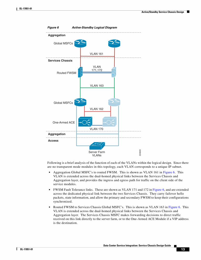
Figure 6 Active-Standby Logical Diagram
Following is a brief analysis of the function of each of the VLANs within the logical design. Since there are no transparent mode modules in this topology, each VLAN corresponds to a unique IP subnet.
• Aggregation Global MSFC’s to routed FWSM. This is shown as VLAN 161 in Figure 6. This VLAN is extended across the dual-homed physical links between the Services Chassis and Aggregation layer, and provides the ingress and egress path for traffic on the client side of the service modules.
• FWSM Fault Tolerance links. These are shown as VLAN 171 and 172 in Figure 6, and are extended across the dedicated physical link between the two Services Chassis. They carry failover hello packets, state information, and allow the primary and secondary FWSM to keep their configurations synchronized.
• Routed FWSM to Services Chassis Global MSFC’s. This is shown as VLAN 163 in Figure 6. This VLAN is extended across the dual-homed physical links between the Services Chassis and Aggregation layer. The Services Chassis MSFC makes forwarding decisions to direct traffic received on this link directly to the server farm, or to the One-Armed ACE Module if a VIP address is the destination.
Services Chassis
Access
Aggregation
Aggregation
VLAN 161
Global MSFCs
Global MSFCs
Server FarmVLANs
Routed FWSM
One-Armed ACE
VLAN171,172
VLAN 163
VLAN 170
VLAN 162
2246
00
13Data Center Service Integration: Service Chassis Design Guide
OL-17051-01

OL-17051-01 Active/Standby Service Chassis Design
• Services Chassis Global MSFC’s to One-Armed ACE. This is shown as VLAN 162 in Figure 6. This is both the ingress and egress interface for traffic being serviced by the ACE Module. The ACE performs Source NAT, which changes the source address of packets that it is forwarding to the server farm. In this way, the return packets must also pass through the ACE to have their destination addresses translated back to that of the original requesting client node. This VLAN is extended across the dual-homed physical links between the Services Chassis and Aggregation layer.
• ACE Module Fault Tolerance link. This link is shown as VLAN 170 in Figure 6, and is extended across the dedicated physical link between the two Services Chassis. This link carries hello traffic and allows configuration synchronization between the two ACE Modules.
• Services Chassis Global MSFC’s to Server Farm VLANs. These VLANs are referenced as the “Server Farm VLANs”, and are shown Figure 6. These VLANs are extended across the dual-homed links to the Aggregation layer, and also extend down into the Access layer to support server connectivity. In the reference topology, eight different VLANs carrying different types of serviced traffic (voice, firewalled-only data, SLB data) were configured; the actual number and purpose of VLANs deployed will be specific to a customer requirement.
Note Not illustrated in Figure 6 is the possibility of having VLANs that carry non-serviced traffic. For server farm subnets that do not require FWSM or ACE services, a traditional hierarchical design data path may be used with these VLANs terminating on the Aggregation layer, with their IP default gateway services provided by the Aggregation layer global MSFC’s.
The next section of this document discusses the physical layers of this model step-by-step and describes the features that are required to build this topology.
Core Layer
Overview
The Core layer of the Active-Standby Services Chassis model is primarily focused on stability and high-performance Layer 3 IP-packet forwarding. It provides a layer of insulation between the Spanning Tree domains at the data center Aggregation layer, and other places in the network. It is typically constructed of two Cisco Catalyst 6500 switches, with purely 10 Gigabit Ethernet or Gigabit EtherChannel interfaces, all configured in a routed mode. Depending on the scale or specific requirements of the Enterprise, this may represent a dedicated data center Core layer, or may actually be a shared Core where other Distribution or aggregation blocks connect, such as campus, WAN/branch, or Internet edge. The two switches in the Core layer of the Active-Standby Services Chassis model are highlighted in Figure 7.
14Data Center Service Integration: Service Chassis Design Guide
OL-17051-01

OL-17051-01 Active/Standby Service Chassis Design
Figure 7 Data Center Core Layer
Scaling the Data Center
A dedicated data center Core layer also provides the capability to deploy multiple Aggregation layer blocks. This will allow the data center to scale to support larger numbers of Access layer switches due to greater Aggregation layer port count, which in turn translates to a greater number of servers that may be supported. There may also be operational factors that cause a network architect to deploy multiple aggregation blocks, such as after a merger of two companies or in a larger organization with multiple distinct business units that demand some physical separation of equipment for security or maintenance window purposes. An example of a data center network topology with multiple aggregation blocks is shown in Figure 8.
Core
Aggregation
Data CenterServer Farm
EnterpriseNetwork
Access
Services
2246
01
15Data Center Service Integration: Service Chassis Design Guide
OL-17051-01

OL-17051-01 Active/Standby Service Chassis Design
Figure 8 Data Center Core with Multiple Aggregation Blocks
If multiple aggregation blocks are connected to the data center Core, the best practice is to maintain the boundary between Layer 2 and Layer 3 within each distinct pair of aggregation switches, so that only routed links are extended to the core. Maintaining this boundary provides the ability to extend VLANs to multiple Access layer switches, but only within the confines of a given Aggregation layer block. This approach provides for greater stability, since a failure within a given Layer 2 Broadcast and Spanning Tree domain will be constrained to that aggregation block.
Services Chassis deployment in a data center with multiple aggregation blocks should be constrained to a separate pair of Services Chassis for each Aggregation layer switch pair. If greater services capacity is required, multiple pairs of Services Chassis may be used with a single aggregation block. It is a best practice not to attach a single pair of Services Chassis to multiple aggregation blocks, which could potentially result in joining two Layer 2 domains by inadvertent misconfiguration. In general, the total bandwidth capacity of an aggregation block is much greater than that of a given set of services, so when scaling a data center to multiple aggregation blocks multiple sets of Services Modules are typically required.
Core
EnterpriseNetwork
2246
02
16Data Center Service Integration: Service Chassis Design Guide
OL-17051-01
OL-17051-01 Active/Standby Service Chassis Design
Features
IP Route Summarization
Routing protocol summarization is a common IP networking practice to keep routing tables small for faster reconvergence and greater stability. In the data center hierarchical network, summarization may be performed at the data center Core or the Aggregation layer. Summarization is recommended at the data center Core if it is a dedicated layer that is separate from the Enterprise core. The idea is to keep the Enterprise Core routing table as concise and stable as possible, to limit the impact of routing changes happening in other places in the network from impacting the data center, and vice versa. If a shared Enterprise Core is used, summarization is recommended at the Aggregation layer. In order to enable summarization, proper IP address allocation must have been used in the assignment of subnets to allow them to be summarized into a single route. Example configurations in this document will show route summarization enabled only at the Aggregation layer.
OSPF Configuration
The Open Shortest Path First (OSPF) protocol is a popular IP Interior Gateway Protocol (IGP), which is often used to provide dynamic routing in Enterprise networks. OSPF Version 2 is standardized in RFC 2328. Common best practices features recommended for configuration of OSPF in the data center model with a Services Chassis include:
• Hello and Dead timer adjustment. The hello and dead timers in OSPF control how often adjacent neighbors transmit hello packets to maintain the adjacent, and how long a neighbor can miss hello packets before considering a neighbor to be dead and tearing down the adjacency. Cisco IOS offers OSPF timers down to millisecond values, but in interest of stability in the data center environment a hello timer of 1 second and dead timer of 3 seconds are recommended. The control plane protocol load on the Aggregation layer switches can be higher in the data center than some other places in the network. The use of millisecond timers can potentially cause undesirable routing protocol peering flaps when other failover events occur in the network, which will in turn increase reconvergence times.
• OSPF Authentication. Authenticating OSPF neighbor routers with a pre-shared message digest key is the preferred way to mitigate the threat of unauthorized devices attempting to form routing adjacencies with data center infrastructure equipment. OSPF Authentication must be mutually configured on both routing neighbors to form an adjacency, with a matching key phrase.
• Passive Interface Default. When configuring the OSPF router in Cisco IOS, change the default behavior for IP routed interfaces to passive. Then, turn off the passive function only on interfaces where an OSPF neighbor is expected in the design. In the Core layer, an OSPF neighbor should really be on all interfaces, other than possibly a management interface that is not participating in routing. The passive default has more bearing in the Aggregation layer, where there are many routed interfaces facing the Access that should not be enabled as active OSPF interfaces. However, it is cleaner to use passive default as a consistent best practice across all of the routing nodes in the network.
• Hard-coded Router ID. By default, OSPF will choose the highest Loopback interface IP address in the router as the Router ID, if there are no loopbacks then it chooses the highest physical interface address. It is desirable to have OSPF router id’s remain consistent and not change, both for routing stability and for troubleshooting purposes. Best practice is to be sure to create a loopback interface on the router to maintain a consistent router id, or use the router-id command in IOS to hardset this value.
17Data Center Service Integration: Service Chassis Design Guide
OL-17051-01

OL-17051-01 Active/Standby Service Chassis Design
• Auto-cost reference bandwidth adjustment. The default reference bandwidth of 100 Mbps results in 10 Gigabit, 1 Gigabit, and 100 Mbps interfaces all to have the same cost. By raising the reference bandwidth to 10,000 Mbps, it is the equivalent of 10 Gigabits, so a 10 Gigabit Ethernet interface will have a cost of 1, and a 1-Gigabit interface will have a cost of 10.
• Throttle timers for SPF and LSA processing. These timer optimizations improve the response time for initial SPF calculation and LSA generation, while maintaining a dampening factor to reduce control plane load in a situation where an interface is flapping.
The following are examples of interface and router OSPF configurations in Cisco IOS with these best practices optimizations applied:
interface TenGigabitEthernet4/1ip address 10.7.2.1 255.255.255.0 ip pim sparse-mode ip ospf authentication message-digest ip ospf message-digest-key 1 md5 c1sc0 ip ospf hello-interval 1 ip ospf dead-interval 3 ip igmp version 3
router ospf 7 router-id 2.2.2.1 log-adjacency-changes auto-cost reference-bandwidth 10000 area 0 authentication message-digest timers throttle spf 10 100 5000 timers throttle lsa all 10 100 5000 passive-interface default no passive-interface TenGigabitEthernet4/1 no passive-interface TenGigabitEthernet4/2 network 10.7.0.0 0.0.63.255 area 0
EIGRP Configuration
Enhanced Interior Gateway Routing Protocol (EIGRP) is a Cisco-specific routing protocol that is commonly used as an IGP in the Enterprise environment. EIGRP does not require the area constructs that OSPF uses, and permits summarization to be configured on a per-interface basis that provides greater flexibility. Best practices for IP subnetting and address allocation should still be followed if summarization is desired. EIGRP provides convergence times that are equal to or slightly faster than OSPF in the validated topologies. Features to enable when leveraging EIGRP in the Active-Standby Services Chassis model include:
• Hello Interval and Hold Time adjustment. The hello interval and hold time in EIGRP control how often neighbors transmit hello packets to maintain the adjacency, and how long a neighbor can miss hello packets before considering a neighbor to be dead and tearing down the adjacency. An EIGRP hello interval setting of one second, and a hold time setting of 3 seconds are recommended for fast reconvergence.
• EIGRP Authentication. Authenticating EIGRP neighbor routers with a pre-shared message digest key is the preferred way to mitigate the threat of unauthorized devices attempting to form routing adjacencies with data center infrastructure equipment. OSPF authentication must be mutually configured on both routing neighbors to form an adjacency, with a matching key phrase.
• Passive Interface Default. When configuring the EIGRP router in Cisco IOS, change the default behavior for IP routed interfaces to passive. Then, turn off the passive function only on interfaces where an EIGRP neighbor is expected in the design. In the Core layer, an EIGRP neighbor should really be on all interfaces, other than possibly a management interface that is not participating in
18Data Center Service Integration: Service Chassis Design Guide
OL-17051-01

OL-17051-01 Active/Standby Service Chassis Design
routing. The passive interface default has more bearing in the Aggregation layer, where there are many routed interfaces facing the access that should not be enabled as active EIGRP interfaces. However, it is cleaner to use passive default as a consistent best practice across all of the routing nodes in the network.
• Disable Auto-Summary. EIGRP has the capability to automatically summarize routes at classful network boundaries. When a network administrator is configuring IP route summarization at the Core or Aggregation layer of a data center topology, this will often not coincide with a transition of classful network space. This is an optional setting, but it is a cleaner configuration to disable the automatic summarization and summarize at the interface level only where dictated by the logical design.
The following are examples of interface and router OSPF configurations in Cisco IOS with these best practices optimizations applied:
interface TenGigabitEthernet13/5ip address 10.7.1.2 255.255.255.0 ip pim sparse-mode ip hello-interval eigrp 7 1 ip hold-time eigrp 7 3 ip authentication mode eigrp 7 md5 ip authentication key-chain eigrp 7 eigrp ip igmp version 3
router eigrp 7 passive-interface default no passive-interface TenGigabitEthernet13/5 no passive-interface TenGigabitEthernet13/6 network 10.0.0.0no auto-summary
Multicast Configuration
IP multicast is commonly leveraged by multi-media applications such as voice conferencing, video broadcasts, and video surveillance. Regardless of the specific applications requirements, at a minimum a basic multicast configuration should be applied to all internetworking devices in the enterprise to ensure that any multicast streams that are introduced to a given IP subnet are not treated as broadcast due to lack of configuration. Depending on application specifics, devices in the data center server farm could be either sources or receivers of multicast streams. A basic multicast configuration requires the following steps:
Step 1 Enable IP multicast routing on all routers in the network.
Step 2 Enable IGMP version 3 on all routed interfaces on the network. Ensure that any required multicast peers are IGMP version 3 capable, if necessary down-rev to IGMP version 2 on specific interfaces. For example, the FWSM supports only IGMP version 2.
Step 3 Enable PIM sparse-mode on all routed interfaces on the network. PIM dense mode should be avoided due to its periodic flooding of multicast traffic. PIM sparse-dense mode may be used if using Auto-RP to facilitate Rendezvous Point discovery. On a routed FWSM, enabling PIM turns on sparse-mode behavior by default.
Step 4 Configure one or more routers in the network to act as a multicast Rendezvous Point. The RP allows multicast routers to discover the availability of sources on specific group addresses. An RP-to-group mapping agent is also required if using a dynamic mechanism for RP discovery.
19Data Center Service Integration: Service Chassis Design Guide
OL-17051-01
OL-17051-01 Active/Standby Service Chassis Design
Step 5 Configure an RP discovery mechanism for multicast routers. The RP address for the multicast group addresses required must be known to all multicast capable routers in the path of a multicast stream. This address may be hard-coded in the routers if necessary. Several dynamic mechanisms also exist, such as Cisco Auto-RP, Auto-RP listener, and Boot Strap Router (BSR). BSR was used between the Core and Aggregation layers in the validation of the Services Chassis models, also static RP addressing was used on the FWSM and Services Chassis routers since the FWSM could not participate in any dynamic RP discovery mechanism.
If hard-coded RP addresses are required in the network , use Anycast RP to provide for RP redundancy. The dynamic RP discovery mechanisms allow for redundant RPs to be configured with different IP addresses. In a network with hard-coded RP addresses another mechanism must be used to allow for redundancy of the RP services. Anycast RP allows two different routers to carry the same IP address on a loopback interface, which provides for a redundant physical set of RPs available at a single IP. Another set of loopback interfaces and a Multicast Source Discovery Protocol (MSDP) peering relationship is used to allow the redundant RP’s to replicate source information.
Aggregation Layer
Overview
The Aggregation layer of the data center provides connectivity for the Access layer switches in the server farm, an aggregates them into a smaller number of interfaces to be connected into the Core layer. In most data center environments, the Aggregation layer is the transition point between the purely Layer 3 routed Core layer, and the Layer 2-switched Access layer. 802.1Q trunks extend the server farm VLANs between Access and Aggregation layers.
The Aggregation layer also provides a common connection point to insert services into the data flows between clients and servers, or between tiers of servers in a multi-tier application. In the Active-Standby Services Chassis model, the Services Chassis are dual-homed into the Aggregation layer with 802.1Q trunks similar to the way that Access layer switches are connected. An illustration highlighting the data center Aggregation layer is shown in Figure 9.
20Data Center Service Integration: Service Chassis Design Guide
OL-17051-01

OL-17051-01 Active/Standby Service Chassis Design
Figure 9 Data Center Aggregation Layer
Features
Layer 2
Port Channel Configuration
Port-Channel interfaces are configured in Cisco IOS to facilitate the bonding of multiple physical ports into a single logical interface; this is also referred to as an EtherChannel. Link Aggregation Control Protocol (LACP) is part of the IEEE 802.3ad specification and is a standards-based mechanism for two switches to negotiate the building of these bundled links. Cisco also supports Port Aggregation Protocol (PAgP), but LACP is the recommended for standards compliance. LACP is configured using the keywords “active” and “passive” in the interface configuration. At least one end of the port-channel connection must be placed in “active” mode for channel negotiation to occur.
Cisco devices allocate traffic across members of an EtherChannel bundle using a hash distribution mechanism. Cisco IOS 12.2(33)SXH and later for the Catalyst 6500 supports an alternative hash-distribution algorithm called the adaptive algorithm. Use of the adaptive algorithm eliminates the reset of the port ASIC on each port in the channel when a single physical port is added to or deleted from the channel. The adaptive algorithm was shown to slightly improve network convergence times during
Core
Aggregation
Data CenterServer Farm
EnterpriseNetwork
Access
Services
2246
03
ExternalServicesChassis
21Data Center Service Integration: Service Chassis Design Guide
OL-17051-01

OL-17051-01 Active/Standby Service Chassis Design
single-port EtherChannel failovers during design validation. The adaptive algorithm may be enabled globally, or on a per-interface basis. If using a global configuration, ensure that all connected endpoints support the use of the adaptive algorithm. An example of port-channel configuration is shown below.
port-channel hash-distribution adaptive
interface Port-channel99 switchport switchport trunk encapsulation dot1q switchport trunk allowed vlan 128-133,161-167,180-183,300-399,999 switchport mode trunk spanning-tree guard loop
interface TenGigabitEthernet13/3 switchport switchport trunk encapsulation dot1q switchport trunk allowed vlan 128-133,161-167,180-183,300-399,999 switchport mode trunk channel-protocol lacp channel-group 99 mode active spanning-tree guard loop
Spanning Tree Configuration
The Active-Standby Services Chassis model was validated using a looped configuration with Access layer switches dual-homed into the Aggregation layer. The looped topology is required in order to facilitate extension of the server farm VLANs into the two redundant Services Chassis. When redundant connections are introduced into the network to provide Layer 2 redundancy, a loop-prevention mechanism is required to prevent broadcast and unknown destination packets from endlessly circling the network. Traditionally, Spanning Tree Protocol (STP), standardized in 802.1D, has provided this function.
Rapid Spanning Tree, (RSTP)
RSTP, which is standardized in IEEE 802.1w, provides faster reconvergence than traditional STP and replaces the need to run the Cisco proprietary extensions of Uplink Fast and Backbone Fast to improve convergence times. Cisco’s implementation of RSTP is known as Rapid Per-VLAN Spanning Tree, (RPVST+, also known as PVRST+) which uses the features of 802.1w and implements a separate Spanning Tree instance for each active VLAN. RPVST+ is the recommended Spanning Tree implementation for the Active-Standby Services Chassis model to provide rapid re-convergence in the event of link or device failure.
Multiple Spanning Tree (MST)
MST, which is standardized in IEEE 802.1s, provides for the consolidation of multiple STP instances that all follow the same topology into a reduced number of STP instances. MST may be used in conjunction with 802.1w to support networks with very large numbers of VLANs, but was not implemented in the validation of this Services Chassis model.
Loop Guard
Loop Guard is a Cisco-specific feature that provides additional protection against Layer 2 forwarding loops. Loop Guard should be enabled on Root and Alternate ports in the Spanning Tree topology. When Loop Guard detects that BPDUs are no longer being received on a non-designated port, the port is moved into a loop-inconsistent state instead of transitioning to the listening/learning/forwarding state. This prevents a Layer 2 loop from occurring in the event that a link becomes unidirectional or a node stops transmitting BPDUs for some reason. Loop Guard may also be configured globally, but port-specific
22Data Center Service Integration: Service Chassis Design Guide
OL-17051-01
OL-17051-01 Active/Standby Service Chassis Design
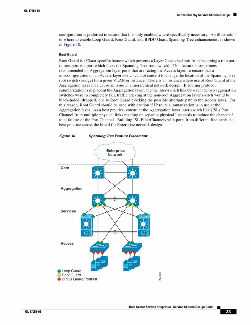
configuration is preferred to ensure that it is only enabled where specifically necessary. An illustration of where to enable Loop Guard, Root Guard, and BPDU Guard Spanning Tree enhancements is shown in Figure 10.
Root Guard
Root Guard is a Cisco-specific feature which prevents a Layer 2 switched port from becoming a root port (a root port is a port which faces the Spanning Tree root switch). This feature is sometimes recommended on Aggregation layer ports that are facing the Access layer, to ensure that a misconfiguration on an Access layer switch cannot cause it to change the location of the Spanning Tree root switch (bridge) for a given VLAN or instance. There is an instance where use of Root Guard at the Aggregation layer may cause an issue in a hierarchical network design. If routing protocol summarization is in place at the Aggregation layer, and the inter-switch link between the two aggregation switches were to completely fail, traffic arriving at the non-root Aggregation layer switch would be black-holed (dropped) due to Root Guard blocking the possible alternate path to the Access layer. For this reason, Root Guard should be used with caution if IP route summarization is in use at the Aggregation layer. As a best practice, construct the Aggregation layer inter-switch link (ISL) Port Channel from multiple physical links residing on separate physical line cards to reduce the chance of total failure of the Port Channel. Building ISL EtherChannels with ports from different line cards is a best practice across the board for Enterprise network design.
Figure 10 Spanning Tree Feature Placement
Core
Aggregation
Loop GuardRoot GuardBPDU Guard/Portfast
EnterpriseNetwork
Access
Services
2246
23
23Data Center Service Integration: Service Chassis Design Guide
OL-17051-01
OL-17051-01 Active/Standby Service Chassis Design
Spanning Tree primary and secondary root assignments should be performed on the Aggregation layer switches for all server farm VLANs. This assignment is according to the principals of classic hierarchical network design. Layer 2 STP root should be assigned to the same switch to which Layer 3 primary default gateway is assigned using HSRP or another First Hop Redundancy Protocol (FHRP). This aligns Layer 2 and Layer 3 paths in the network to eliminate any unnecessary hops. In the Active-Standby design, the topology is intentionally one-sided for simplicity of implementation and troubleshooting, so all server farm STP roots and HSRP primary routers should be configured on Aggregation 1, indicated on the left side of the topology.
Layer 3
IP Routing Best Practices
In general, the configuration of OSPF and EIGRP routing protocols in the Aggregation layer to peer with the Core layer follows the same best practices as the Core. Hello and dead timers, neighbor authentication, and passive interface default are all best practices common to both OSPF and EIGRP routing protocols. For OSPF specifically, hard-set Router ID, auto-cost reference bandwidth adjustment, and throttle timer adjustment are also recommended. Refer to the “Core Layer” section on page 14, for specifics on these recommendations.
IP Route Summarization
As mentioned in the “Core Layer” section on page 14, IP route summarization may be performed at the data center Aggregation or Core layer. Core layer IP route summarization is more appropriate when there is a dedicated data center Core which is separate from the Enterprise Core, typically when multiple Aggregation blocks exist in the data center. Aggregation layer IP route summarization is more appropriate when there is a shared Enterprise Core, and the data center contains only one Aggregation block with the switches performing a dual role as a collapsed Core and Aggregation layer for the data center.
IP route summarization is configured differently between the OSPF and EIGRP Routing protocols. EIGRP allows summarization anywhere in the topology that the IP addressing will allow. This is configured at the interface level, on every interface that advertises the route to the portion of the network being summarized. The following IOS configuration example illustrates EIGRP route summarization:
interface TenGigabitEthernet1/1 ip address 10.7.3.2 255.255.255.0 ip summary-address eigrp 10.7.128.0 255.255.192.0 5
OSPF requires an area structure, which is often mapped to chunks of IP address space that can be summarized at a bit boundary. The Area Border Router (ABR) defines the border between OSPF areas and is the logical point for IP route summarization. OSPF syntax in Cisco IOS allows route summarization to be performed directly in the router ospf portion of the configuration:
router ospf 7router-id 3.3.3.1 area 71 range 10.7.128.0 255.255.192.0
When configuring an Area Border Router for OSPF in the data center, the interfaces facing the data center should be placed in a numbered, non-zero assigned OSPF area. This area identifier is used during route summarization. The interfaces pointing towards the Enterprise Core should be in Area 0, which defines the “backbone area” of the OSPF Autonomous System.
24Data Center Service Integration: Service Chassis Design Guide
OL-17051-01
OL-17051-01 Active/Standby Service Chassis Design
Static Routing Requirements
The validated architecture for the Active-Standby Services Chassis model uses statically configured IP routes between the Aggregation layer and the routed-mode Firewall Services Module (FWSM.) The FWSM is optimized as a security device, and while it does support OSPF, there are design advantages to the use of static IP routing at this layer. Details of this architecture decision are discussed in the Services Chassis portion of the Active-Standby model. Static IP routes are required for each of the server farm VLANs that have default gateway services on the Services Chassis MSFC’s. When using static routes to the FWSM, the Aggregation layer MSFC’s only use a dynamic routing protocol to peer with the Core layer.
Non-Serviced Traffic Option
In many data centers, not all traffic destined to the server farm may be required to transit the services modules. The Active-Standby Services Chassis model supports the capability of configuring non-serviced server farm VLANs and IP subnets, which terminate directly on the Aggregation layer. This is a similar approach to the basic hierarchical network design without services. The Aggregation layer MSFC's provide IP default gateway for these subnets, and the VLANs are not extended across the trunks to the Services Chassis. A given server farm VLAN and IP subnet should not be extended between the non-serviced and Services Chassis domains.
Default Gateway Redundancy
Redundant IP default gateway services may be provided using several available First Hop Redundancy Protocols (FHRPs). These protocols include Hot Standby Router Protocol (HSRP), Gateway Load Balancing Protocol (GLBP), and Virtual Router Redundancy Protocol (VRRP). For validation of the Active-Standby Services Chassis model, HSRP was chosen since it is widely deployed and stable. A single gateway address is desirable per subnet to support better control of traffic paths through the network when implementing services.
HSRP hello and dead timers should be configured to match the routing protocol timers being used in the network; a one-second hello and three-second dead timer are recommended. HSRP supports authentication of peers, which is desirable to prevent an unintended device from participating in the negotiation of active gateway. The priority needs to be set higher on the HSRP peer router that will act as the primary default gateway when all components in the design are up and running normally.
HSRP preemption is a feature that allows an HSRP peer with a higher priority to regain control of the shared IP and mac address for gateway services. Preemption is desirable during the restoration of a device that was previously failed. However, it is possible when re-inserting a previously failed switch into the network that it may attempt to preempt HSRP active status before all interfaces are ready to forward traffic during a boot process. For that reason, a damping timer of 180 seconds is recommended on HSRP preemption, to ensure that a switch is fully booted and all interfaces are functioning normally before HSRP active status is resumed. An example of HSRP interface configuration is shown below:
interface Vlan128 ip address 10.7.128.3 255.255.255.0 ip pim sparse-mode ip igmp version 3 standby 1 ip 10.7.128.1standby 1 timers 1 3 standby 1 priority 20 standby 1 preempt delay minimum 180 standby 1 authentication c1sc0
Multicast
See Core Layer, page 14 for best practices on multicast configuration.
25Data Center Service Integration: Service Chassis Design Guide
OL-17051-01

OL-17051-01 Active/Standby Service Chassis Design
Services ChassisThe following section describes the physical and logical design of the Services Chassis in the Cisco data center architecture.
Overview
Physical Topology
High availability requirements in the data center demand that network services and service paths are deployed redundantly removing any one single point of failure. As a result, the service chassis switches are deployed in pairs dual-homed to the Aggregation layer switches and directly attached to one another. Figure 11 illustrates the physical layout of the Services Chassis design. In this example, each of the services switches is hosting a single FWSM and ACE service module.
The direct connection between the services switches is an 802.1q trunk providing a direct and dedicated path for service module fault tolerant traffic including:
• Service device heartbeats and probes
• Configuration synchronization
• Replicated connection state information
Figure 11 Service Chassis Physical Connectivity
The Service Chassis Inter-Switch Link (ISL) does not support user data traffic; it is dedicated to fault tolerant control traffic between service modules. To improve resiliency, the Services Chassis ISL is configured as an EtherChannel, removing a single point of failure.
Note It is recommended to distribute the connections between aggregation and services switches across physical linecards to improve infrastructure availability.
In this model, the Services Chassis’s employs 10 Gigabit Ethernet links to the Aggregation layer and in the fault tolerant ISL configuration. The introduction of 10 Gigabit Ethernet to the service chassis is not a strict requirement. However, given the current industry trends of data center and server consolidation, increasing server density and load within a single Aggregation layer block of the data center is expected; therefore, applications and network services should be sized appropriately.
Aggregation
Services
2246
77Fault Tolerant ISL
26Data Center Service Integration: Service Chassis Design Guide
OL-17051-01
OL-17051-01 Active/Standby Service Chassis Design
The fault tolerant ISL bandwidth requirement is dependent on the number of service modules within the services switches and the amount of fault tolerant traffic generated by these devices on the link. The FWSM and the ACE do not require the bandwidth of 10 Gigabit Ethernet connections for fault tolerant traffic; in fact, a single Gigabit Ethernet connection would suffice for each. During testing, the available 10 Gigabit Ethernet ports on the Supervisor 720 were leveraged as the ISL between Services Chassis's.
Figure 11 shows the physical connectivity between the Services Chassis’s and the Aggregation layer switches. There are redundant physical paths present in this design. The following section details the logical topology under the covers and the steps necessary to deploy a stable service chassis environment.
Note Although not tested for this document, it is feasible to deploy a single service chassis switch leveraging redundant supervisors supporting a multitude of redundantly deployed network service devices for a single aggregation block in the data center.
Logical Topology
Figure 12 illustrates the logical topology of the Active-Standby Services Chassis design. As shown in this drawing, the Services Chassis switches employ the following components and features:
• Layer 2 switching
• Layer 3 routing
• The FWSM (routed mode)
• The ACE (one-arm mode)
27Data Center Service Integration: Service Chassis Design Guide
OL-17051-01

OL-17051-01 Active/Standby Service Chassis Design
Figure 12 Active-Standby Logical Design
Layer 2
From a Layer 2 perspective the Services Chassis is supporting multiple VLANs created either for user data or fault tolerant traffic support. In Figure 12, VLANs 171 and 172 provide fault tolerant connectivity between the active and standby FWSM, while VLAN 170 provides a similar service for the virtual Active-Standby ACE contexts. These VLANs reside on the ISL between Services Chassis.
VLANs 161, 162 and 163 in Figure 12 support user data traffic between the FWSM, the MSFC and the ACE context. These VLANs span the services switches via the Aggregation layer. This is required to meet the Layer 2 adjacency requirements of a redundant service module deployment.
Services Chassis
Access
Aggregation
Aggregation
VLAN 161
Global MSFCs
Global MSFCs
Server FarmVLANs
Routed FWSM
One-Armed ACE
VLAN171,172
VLAN 163
VLAN 170
VLAN 162
2246
00
28Data Center Service Integration: Service Chassis Design Guide
OL-17051-01

OL-17051-01 Active/Standby Service Chassis Design
Figure 13 Active-Standby Traffic Flow
Features
Physical Connectivity
The Active-Standby Services Chassis model is based on a physical architecture with dual-homed trunks into the Aggregation layer, and a dedicated ISL between the Services Chassis for fault tolerance traffic. Multiple combinations of physical ports could be used to set up this connectivity. The types of ports that are used can affect the configuration requirements for the modules and Layer 2 switching features to ensure high availability. The Services Chassis models may often be used in migration scenarios where modules previously lived directly in the Aggregation layer switches, so spare equipment on hand may be what is being employed to build out the necessary connections. However, several factors should be considered carefully in establishing this connectivity.
• Physical Throughput. The total maximum bandwidth capacity of the modules being deployed should be considered when planning the physical connectivity. The maximum throughput of the ACE Modules is on the order of 16 Gbps. The FWSM with software version 3.2 supports a maximum throughput of 5.5 Gbps. The physical bandwidth capacity of each of the dual-homed links should well exceed the capacity of the modules, or at least the expected capacity of the aggregate end servers that are passing their traffic through the modules.
• Planned and Failover traffic paths. The Services Chassis model is inherently more complex at Layer 2 and Layer 3 than an Integrated Services model with services directly in the Aggregation layer, since there are four physical switches in the service topology instead of only two. Plan for the possibility that in certain failover scenarios if dynamic routing protocols are used, a portion of the traffic may need in ingress and egress a given Services Chassis more than once. This is due to ECMP and should affect only a portion of the traffic; the use of static routes provides more granular path control and can help eliminate these scenarios. If the Services Chassis model is being adapted to serve in a multi-tier application environment, you may consider services both in front of a Web/Application server and also between the Web/Application server and a Database server. These additional traffic flows should be taken into account in bandwidth allocation.
Active Chassis 1
Data Center Core
Agg 1
Server Side
Client Side
Active Chassis 2Agg 2
Access/Server Farm
2245
97
29Data Center Service Integration: Service Chassis Design Guide
OL-17051-01

OL-17051-01 Active/Standby Service Chassis Design
• Use of EtherChannel. The use of 10 Gigabit EtherChannel is recommended for the construction of the dual-homed links to the Aggregation layer, 1 Gigabit-based EtherChannel may suffice depending on customer bandwidth requirements and failover paths. The most robust configuration will include ports from two different line cards in the EtherChannel, so that an individual linecard failure cannot take down the entire Port Channel interface.
• Line Card Combinations. High availability should be considered and the potential link or device failures in the active path before completing Layer 2 and service module configuration. Following are some examples of combinations of line cards and considerations for their deployment.
– Two 8 or 4-port 10-Gigabit cards per chassis. This is the most robust combination. Two or more ports of 10 Gigabit Ethernet should be used to form each EtherChannel connection into each Aggregation layer switch. Each EtherChannel should use ports that are spread across the two different line cards for high availability. Two additional ports of 10 Gigabit Ethernet should be used to build the fault tolerance ISL between Services Chassis.
– One 8-port 10 Gigabit card per chassis. In this model, EtherChannel connections may still be used from each Services Chassis to each Aggregation layer switch. The dedicated fault tolerance EtherChannel should also be built from ports on the same 8-port 10 Gigabit linecard. An important aspect of this approach to consider is that if the linecard itself fails, it will bring down both data path EtherChannels as well as the fault tolerance link.
– One 4-port 10 Gigabit card per chassis. In this model, one could choose to build the two dual-homed links each out of single 10-Gigabit ports as opposed to EtherChannel. This would leave two ports open to build the Fault Tolerance ISL. Another possible approach would be to use EtherChannel for the data path links, which would consume all of the 10-Gigabit ports on each line card to connect to both Aggregation layer switches. If two 1-Gigabit ports are available from each of the supervisors, these could then be used to build the fault tolerance Link.
Note If the data path connections are being deployed using a single linecard that is separate from the fault tolerance links, one must consider and plan for an additional possible failure mode. If the linecard carrying the data path links were to fail, but the separately configured fault tolerance ISL remains up, the standby modules may not realize that the primary modules now have no data path connectivity. Interface monitoring on the service modules may be used to ensure that the primary modules relinquish their active status if this occurs. The fastest failover occurs with the use of interface monitoring in conjunction with firewall and Service Line Card (SVCLC) autostate. The implementation of interface monitoring with autostate also has some side effects which are discussed in the following section.
Interface Monitoring and Autostate
Standard autostate is a mechanism which is enabled by default in the Cisco Catalyst 6500 for the integrated Layer 3 routing engine, the Multilayer Switch Feature Card (MSFC). Autostate is used to notify the MSFC when there are no longer any active physical ports in a given VLAN. If a routed VLAN interface for this VLAN has been defined on the MSFC, the routed interface is moved to a “down” state if no physical ports in the switch are forwarding traffic for the VLAN. This mechanism allows the IP route for this VLAN to be removed from the routing table, and no longer advertised to IGP peers, until once again physical ports in the switch become active for that VLAN.
The services modules in the Cisco Catalyst 6500 support similar autostate mechanisms. These mechanisms are not enabled by default. For the FWSM, the keyword firewall is used when enabling autostate, for the ACE, the keyword svclc is used. Examples of the Cisco IOS configuration used to enable these capabilities is shown below.
firewall autostatefirewall multiple-vlan-interfacesfirewall module 4 vlan-group 1,2,3,
30Data Center Service Integration: Service Chassis Design Guide
OL-17051-01

OL-17051-01 Active/Standby Service Chassis Design
firewall vlan-group 1 146firewall vlan-group 2 171,172firewall vlan-group 3 161,163analysis module 2 management-port access-vlan 146svclc autostatesvclc multiple-vlan-interfacessvclc module 5 vlan-group 1,52,162,999,svclc vlan-group 52 170svclc vlan-group 162 162svclc vlan-group 999 999
Similar to standard MSFC autostate, firewall and svclc autostate will notify the FWSM and ACE respectively, if all of the physical interfaces carrying a specific VLAN address are down. If the module is using interface monitoring as a criterion for failover of the active status, the autostate will provide much faster failover of the modules than the standard mechanisms integrated into the modules.
The decision to run autostate is tightly tied to the Spanning Tree design of the services region of the network. The number of active interfaces in the Spanning Tree table for a given VLAN is used as the criteria for when the switch sends and autostate up or down notification to a service module. If standard hierarchical network design practices are followed, the Aggregation layer switches are set to be primary and secondary STP root. In this way, the path to to STP root for the primary services switch in the model is the link to Aggregation 1. If this link experiences a failure, one would expect traffic to reroute to Services Chassis 1 through Aggregation 2. However, if Services Chassis 1 sees its path to STP root change, then all ports on the VLAN briefly stop forwarding traffic while the Spanning Tree is recalculated. This brief outage also triggers an Autostate Down message from the Services Switch 1 Layer 2 engine to the FWSM, causing the active status to transition to the secondary FWSM, and then back. This flapping of active status on the FWSM can significantly increase the reconvergence time for the failure cases of the Aggregation 1 to Service Chassis 1 link failure, or the case of the failure of Aggregation 1 itself.
To work around this issue, one may consider configuring the STP root of only the service-specific VLANS onto the Services Chassis instead of the Aggregation. This step should not be taken for the server farm VLANs themselves. Specific benefits and implications of this design decision are discussed in the “Services Chassis Spanning Tree Specifics” section on page 31.
Layer 2
The Services Chassis leverage common networking features providing Layer 2 connectivity to the services modules allowing traffic to flow through the active modules. Best practices for configuration of these features have already been covered under the core and Aggregation sections of the Active-Standby Services Chassis model description. These features include:
• PortChannel/EtherChannel with LACP and adaptive hash algorithm
• Spanning Tree Loop Guard (enabled on dual-homed links of Services Chassis)
• Rapid Per-VLAN Spanning Tree (RPVST)
Services Chassis Spanning Tree Specifics
The classical hierarchical network design model with the Layer 2 / Layer 3 boundary at the Aggregation layer dictates STP priority be manipulated on the aggregation switches to force the location of a primary and secondary STP root switch. This creates a consistent, deterministic Spanning Tree root bridge location for each of the access switches in the Looped Triangle and Looped Square topologies that are discussed in “Access Layer” section on page 60. When analyzing STP configuration for the services region, consider again the logical layout of the Active-Standby Services Chassis model as shown in Figure 14.
31Data Center Service Integration: Service Chassis Design Guide
OL-17051-01

OL-17051-01 Active/Standby Service Chassis Design
Figure 14 Active-Standby Services Chassis Logical Model
The VLANs between the service modules and the Aggregation layer as well as the VLANs between layers of services, must all be extended between the two Services Chassis across the dual-homed physical links to the Aggregation. The set of VLANs defining the services region as shown in Figure 14 include VLAN 161,162, and 163. This VLAN extension provides contiguous IP subnetting, and failover paths required for high availability of the solution. If the classical hierarchical network design approach is taken when connecting the Active-Standby Services Chassis model, the resulting Spanning Trees for each of the VLANs in question will be similar to the illustration in Figure 15
Services Chassis
Access
Aggregation
Aggregation
VLAN 161
Global MSFCs
Global MSFCs
Server FarmVLANs
Routed FWSM
One-Armed ACE
VLAN171,172
VLAN 163
VLAN 170
VLAN 162
2246
00
32Data Center Service Integration: Service Chassis Design Guide
OL-17051-01
OL-17051-01 Active/Standby Service Chassis Design
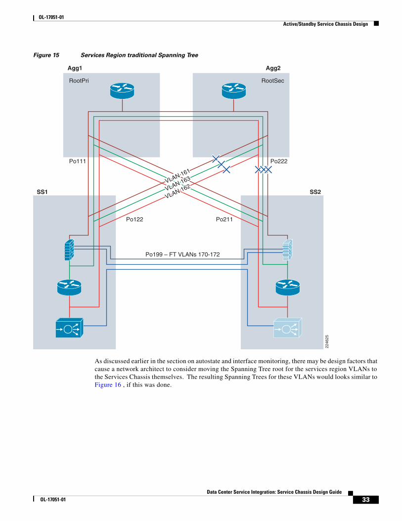
Figure 15 Services Region traditional Spanning Tree
As discussed earlier in the section on autostate and interface monitoring, there may be design factors that cause a network architect to consider moving the Spanning Tree root for the services region VLANs to the Services Chassis themselves. The resulting Spanning Trees for these VLANs would looks similar to Figure 16 , if this was done.
Po111 Po222
Po122
Po199 – FT VLANs 170-172
VLAN 161
VLAN 163
VLAN 162
Po211
RootPri RootSec
Agg1 Agg2
SS1 SS2
2246
25
33Data Center Service Integration: Service Chassis Design Guide
OL-17051-01

OL-17051-01 Active/Standby Service Chassis Design
Figure 16 Services Region Altered STP Root
There are pros and cons to this design decision. Moving the Spanning Tree root for the services region VLANs will work around the issue of path to STP root changing and causing Autostate notification and Services module flapping if interface monitoring is in use. As shown in Figure 16, the movement of the Spanning Tree root also opens up the direct Layer 2 forwarding path between Agg2 and SS1. This provides for a cleaner flow of traffic through the network in an “all normal” state with all modules, switches and links in the topology up and running.
Note SS 2 in Figure 16 effectively has two equal cost paths to reach the STP root switch in SS1. These are the paths through Agg1 and Agg2. When equal cost paths exist in STP, the tie is broken based on the bridge ID which is the MAC address of the switch. Ideally, the path to Agg1 should be open and the path through Agg2 should be blocked when using static routes, since the HSRP primary address that the static route points to will reside on Agg1. If STP does not converge that way due to the MAC address
Po111 Po222
Po122
Po199 – FT VLANs 170-172
VLAN 161
VLAN 163
VLAN 162
Po211
RootPri RootSec
Agg1 Agg2
SS1 SS2
2246
26
34Data Center Service Integration: Service Chassis Design Guide
OL-17051-01

OL-17051-01 Active/Standby Service Chassis Design
of Agg2 being lower, then increase the STP cost on the PortChannel connection to Agg 2, to force the Spanning Tree to converge as shown in Figure 16. Use the spanning-tree cost command and increment the cost from the default cost of 1 to the value of 2.
The downside of moving the Spanning Tree root to the Services Chassis is that it can cause suboptimal failover paths for a portion of the traffic in certain failure cases if OSPF is being used on the FWSM, causing traffic to need to ingress and egress the primary Services Chassis twice. If Services Chassis physical connectivity has been provisioned with adequate capacity as recommended, this may not be an issue for a backup path. One of the initial goals of this Services Chassis architecture analysis was to optimize traffic paths for the normal state of the network first, before focusing on failover cases. Also, if static routes are in use on a routed FWSM, such as the approach that was used in validation of this model, these suboptimal paths will not occur. Static routes eliminate the FWSM attempting to use OSPF Equal Cost Multi Path (ECMP) to balance traffic to both peering routers, and instead direct the traffic only to the active HSRP default gateway.
Note Using static routes pointing to an HSRP default gateway address is not supported for multicast traffic through the FWSM in software version 3.2 as used for validating this architecture. If IP multicast is a requirement, running OSPF on the FWSM may be used as an alternate approach.
Layer 3
The Services Chassis also leverage common networking features providing Layer 3 routed connectivity to the services modules allowing traffic to flow through the Active modules. Best practices for configuration of these features have already been covered under the Core and Aggregation sections of the Active-Standby Services Chassis model description. These features include:
• Hello and dead/hold timer adjustments
• Neighbor authentication
• Passive interface default
• Hardset router ID
• No Auto-Summary (EIGRP)
• Auto-Cost Reference Bandwidth (OSPF)
• Throttle Timer adjustment (OSPF)
• Multicast best practices
• HSRP Optimization
Note The Layer 3 configurations in the Services Chassis exist primarily to provide a segmentation of the ACE VIP VLAN away from the true server farm VLANs. This also provides for local Route Health Injection of VIP host routes from the ACE to control SLB traffic flows, if dynamic routing on the FWSM is used. This approach provides additional security since the application clients need not know the true address space of the real servers. The non-SLB server farm subnets also leverage the Services Chassis MSFC as default gateway for consistency, and to provide flexibility to insert additional services into the service chain at a later time without requiring server farm default gateway changes. If ACE services are not required in the Services Chassis, the MSFC Layer 3 configuration may optionally be eliminated, and server farm VLANS may be terminated with their default gateway directly on the FWSM.
35Data Center Service Integration: Service Chassis Design Guide
OL-17051-01

OL-17051-01 Active/Standby Service Chassis Design
Specific Layer 3 optimizations are required for use of OSPF or static routing to be compatible with configuration on the FWSM . Additional HSRP tracking features are required for aligning default gateway services with the active ACE modules in failover scenarios. Detailed configuration information for these requirements is provided in the discussions of the FWSM- and ACE-specific sections that follow. Below is an example configuration of the Services Chassis MSFC with an OSPF configuration in place for peering with the FWSM, and the necessary redistribution statements and route-maps to support the server VLANs and RHI injected statics.
router ospf 7 router-id 4.4.4.1 log-adjacency-changes auto-cost reference-bandwidth 10000 area 71 authentication message-digest area 71 nssa timers throttle spf 10 100 5000 timers throttle lsa all 10 100 5000 redistribute connected metric 10 metric-type 1 subnets route-map OSPF redistribute static subnets route-map RHI-MAP passive-interface default no passive-interface Vlan163 network 10.7.163.0 0.0.0.255 area 71!access-list 10 permit 10.7.162.100access-list 100 deny ip 10.7.162.0 0.0.0.255 anyaccess-list 100 deny ip 172.0.0.0 0.255.255.255 anyaccess-list 100 permit ip any anyroute-map OSPF permit 10 match ip address 100!route-map RHI-MAP permit 10 match ip address 10 set metric-type type-1!
FWSM
Overview
In the Active-Standby Services Chassis model, the FWSM is configured as a single-context in routed mode employing an active/standby fault tolerant configuration. In an active/standby configuration, only one of the firewall modules will pass traffic and the other will be in a STANDBY READY state. As shown in Figure 17, the FWSM is a routed hop in the data center’s logical topology. The firewall is positioned between the MSFCs at the Aggregation layer and the MSFCs on the local Services Chassis switches. The FWSM employs two VLAN interfaces for user traffic, the “north” public interface (VLAN 161) and the “south” private interface (VLAN163). Secure access to the data center server farm is controlled via the FWSM policies associated with these interfaces, allowing network administrators to reliably apply firewall-based security via IP routing.
Note Although not validated in this model, the FWSM may be also positioned as the default gateway for the servers in the server farm. If the FWSM is leveraged as the default gateway for a server subnet, any server-to-server traffic between subnets would be firewalled as well. For example, n-tier applications using application-to-database server connectivity could be secured.
36Data Center Service Integration: Service Chassis Design Guide
OL-17051-01

OL-17051-01 Active/Standby Service Chassis Design
Note The introduction of additional service requirement may require traversing the FWSM or other service modules such as the ACE, multiple times that may impact the overall capacity of the solution.
Figure 17 Active-Standby Combined Layer 2 and Layer 3 Topology
From its earliest release, the FWSM has supported static routes and dynamic routing protocols such as OSPF and RIP. In the FWSM 4.0 Release, EIGRP has been added to the list of routing features supported on the platform. The use of dynamic routing can simplify configuration complexity. However, this dynamic intelligence requires the consumption of resources by requiring the firewall to act as a router.
During testing, convergence times were decreased by removing the OSPF process and making use of static routes to direct traffic across the firewall context. Removing the delay of neighbor establishment and routing table loads from the failover process expedited convergence. Although static routes may add some management overhead, faster network convergence and the inherent security of predefined routes within the data center may outweigh that burden. Use of static routing also eliminates the Equal Cost Multi Path (ECMP) feature of dynamic routing. The elimination of ECMP for subnets carrying service traffic can help provide more granular control over traffic paths between the Aggregation and Services Chassis.
Note FWSM does not support dynamic routing in multiple context mode.
VLAN 163
10.7.163.x/24 HSRP .1
VLAN 16110.7.161.x/24 HSRP .1
.3 .2
.3 .2
.3 .2
.5 .4
.1
.1 .2
.2
.5
.1 .2
.6
.5 .6VLAN
171,172
10.7.171.x/2410.7.172.x/24
VLAN 170
10.7.170.x/24
VLAN 999
10.7.99.x/24
VLAN 162
10.7.162.x/24 HSRP .1
Services Chassis
Aggregation
Global MSFCs
Global MSFCs
Routed FWSM
One-Armed ACE22
4678
37Data Center Service Integration: Service Chassis Design Guide
OL-17051-01

OL-17051-01 Active/Standby Service Chassis Design
Note As stated in the FWSM 3.2 configuration guide, Cisco recommends using the advanced routing capabilities of the upstream and downstream routers instead of relying on the FWSM for extensive routing needs.
As previously mentioned, the FWSM is in an active/standby configuration using two fault tolerant VLAN interfaces. The failover interface, in this example VLAN 172, is mandatory to provide a redundant stateless firewall deployment. For stateful failover, dedicate a VLAN interface to replicate state information to the standby unit, in this example VLAN 171. Each of these VLANs resides on the ISL between services switches and is not present at the Aggregation layer.
Catalyst 6500 IOS Implementation
The FWSM physically resides in the Cisco Catalyst 6500 switching platform. To leverage this integrated service the following tasks must be completed:
• Create the VLANs to support traffic ingress and egress from the FWSM, and fault tolerance communication between the modules.
• Allow the FWSM to leverage the autostate messaging capabilities of the 6500-supervisor engine. Autostate reporting by the supervisor indicates the status of the physical interfaces of the VLANs associated with the FWSM on the switch, permitting Rapid Link Failure Detection by the FWSM. Rapid Link Failure Detection bypasses a number of interface monitoring tests, which expedites the failover process.
Note The use of autostate and interface monitoring is optional if data and fault tolerant VLANs share the same physical interfaces. See the “Physical Connectivity” section on page 29.
• Allow multiple VLAN interfaces (SVI) to be connected with the FWSM if there are more than one VLAN with an SVI leveraged by the FWSM. In this example, VLAN 146 (the management VLAN) and VLAN 163 each have a SVI on the Catalyst 6500, therefore the multiple VLAN interface configuration is necessary for the firewall module.
• Assign the VLANs to firewall VLAN groups
• Assign the VLAN groups to the associated firewall module
The following example highlights the tasks defined above:
vlan 146vlan 161vlan 163vlan 171vlan 172firewall autostatefirewall multiple-vlan-interfacesfirewall module 4 vlan-group 1,2,3,firewall vlan-group 1 146firewall vlan-group 2 171,172firewall vlan-group 3 161,163
To verify the configuration of the FWSM from the perspective of the Catalyst switch, issue the following commands: show firewall module and show firewall vlan-group. In our example, the FWSM in slot 4 of the Services Chassis has three VLAN group assignments that are defined as follows:
dca-ss1#show firewall module Module Vlan-groups------ -----------
38Data Center Service Integration: Service Chassis Design Guide
OL-17051-01

OL-17051-01 Active/Standby Service Chassis Design
04 1,2,3
dca-ss1#show firewall vlan-group Display vlan-groups created by both ACE module and FWSM
Group Created by vlans----- ---------- ----- 1 FWSM 1462 FWSM 171-172 3 FWSM 161,163 52 ACE 170 162 ACE 162 999 ACE 999
Note The show firewall vlan-group command is the equivalent to the show svclc vlan-group command that details the VLAN assignment of the ACE and FWSM service modules present in the chassis.
Fault Tolerant Implementation
The following section details the fault tolerant configuration of an active/standby pair of redundant stateful firewall modules.
• Define the role of the primary FWSM unit and the corresponding secondary unit. This must be done on each FWSM in prior to enabling failover
• Enable preemption to allow the primary unit to become the active firewall after recovering from a failure event or system restart. In this example, the configured delay is 30 seconds, which is ample time for convergence at Layer 2 and 3 to occur before resuming the active role. Preemption was enabled to provide a predictable traffic pattern in the data center when under normal operating conditions.
• Define the FWSM failover interface including the IP addressing of the primary and standby units. VLAN 172 carries the hello messages between FWSM peers. To secure the communications across this link leverage a “shared” failover key.
• Define the FWSM state replication interface. The replication of HTTP traffic allows for stateful failover of this protocol and will increase the bandwidth requirements of the Services Chassis ISL. In the example below, VLAN 171 supports fault tolerant state information defining a primary and standby host IP address.
• Characterize the polling timers for the failover pair. The unit poll time refers to the frequency of the polling Hello’s across the fault tolerant Services Chassis ISL. In testing, this was set to a 1-second interval. The hold time is the period of time a given unit must receive a hello from its peer. If hellos are not received within the delineated timeframe the peer unit will begin failover unit testing. As a rule, the hold time cannot be less than 3 times the poll time.
• Configure the interface poll time to 3 seconds. This is the poll time for monitored interfaces and is set to the minimum.
• Provision an interface policy. The interface policy defines the criteria for failover based on the status of the FWSM interfaces. This rule is applicable as a percentage of interfaces assigned to the context or a maximum number of interfaces that must fail to force a FWSM failover. As shown below, the FWSM has a limit of one interface failure to initiate a failover. This is the logical approach as the loss of one interface, the “north” or “south” VLAN interface, will result in the black holing of traffic.
The following output is the final configuration for our primary FWSM unit:
failover
39Data Center Service Integration: Service Chassis Design Guide
OL-17051-01

OL-17051-01 Active/Standby Service Chassis Design
failover lan unit primary *See Note Belowfailover preempt 30failover lan interface failover Vlan172failover polltime unit 1 holdtime 3failover polltime interface 3failover interface-policy 1failover key *****failover replication httpfailover link state Vlan171failover interface ip failover 10.7.172.1 255.255.255.0 standby 10.7.172.2failover interface ip state 10.7.171.1 255.255.255.0 standby 10.7.171.2
Note The unit failover poll times can be configured in the millisecond range.
Note The secondary FWSM unit will have the same fault tolerant configuration, except the failover lan unit is defined as secondary.
The FWSM is capable of monitoring interfaces via probes or hello messages. In this design, the health of the “north” and “south” VLAN interfaces are scrutinized. When autostate messages are enabled on the Catalyst supervisor engine (see IOS configuration section above), the traditional monitor interface tests are bypassed and the autostate status from the supervisor is honored.
monitor-interface in161monitor-interface in163
To verify the fault tolerant configuration of the FWSM and the status of its corresponding peer , use the show failover command for a comprehensive view of the environment. Below is an example of the show failover command output:
# show failoverFailover On Failover unit PrimaryFailover LAN Interface: failover Vlan 172 (up)Unit Poll frequency 1 seconds, holdtime 3 secondsInterface Poll frequency 3 secondsInterface Policy 1Monitored Interfaces 2 of 250 maximumfailover replication httpConfig sync: activeVersion: Ours 3.2(4), Mate 3.2(4)Last Failover at: 14:20:34 EST Jun 4 2008 This host: Primary - Active Active time: 517573 (sec) Interface mgmt (172.26.146.104): Normal (Not-Monitored) Interface in161 (10.7.161.5): Normal Interface in163 (10.7.163.5): Normal Other host: Secondary - Standby Ready Active time: 615563 (sec) Interface mgmt (172.26.146.106): Normal (Not-Monitored) Interface in161 (10.7.161.6): Normal Interface in163 (10.7.163.4): Normal
Stateful Failover Logical Update Statistics Link : state Vlan 171 (up) Stateful Obj xmit xerr rcv rerr General 198338 0 72772 0 sys cmd 69255 0 69253 0
40Data Center Service Integration: Service Chassis Design Guide
OL-17051-01

OL-17051-01 Active/Standby Service Chassis Design
up time 0 0 0 0 RPC services 0 0 0 0 TCP conn 0 0 0 0 UDP conn 0 0 0 0 ARP tbl 129083 0 3519 0 Xlate_Timeout 0 0 0 0 AAA tbl 0 0 0 0 DACL 0 0 0 0
Logical Update Queue Information Cur Max Total Recv Q: 0 2 601202 Xmit Q: 0 0 198338
Refer to http://www.cisco.com/en/US/docs/security/fwsm/fwsm32/configuration/guide/fail_f.html for more information regarding the configuration of failover on the FWSM.
Interface Configuration
The active/standby single context routed mode configuration uses four interfaces as defined previously in the FWSM Overview, page 36 . The fault tolerant VLAN interfaces are defined as such:
interface Vlan171 description STATE Failover Interface!interface Vlan172 description LAN Failover Interface
This is the only interface configuration required as the fault tolerant Layer 3 IP information is defined by the failover configuration of the primary and secondary firewalls. To verify the configuration use the show failover interface command. For example:
show failover interface interface failover Vlan172 System IP Address: 10.7.172.1 255.255.255.0 My IP Address : 10.7.172.1 Other IP Address : 10.7.172.2 interface state Vlan171 System IP Address: 10.7.171.1 255.255.255.0 My IP Address : 10.7.171.1 Other IP Address : 10.7.171.2
The FWSM VLAN interfaces “north” and “south” exist on different subnets. Each interface has it own IP address and security level. The following illustrates the interface configuration of the “north” and “south” VLAN interfaces without OSPF enabled. See Routing (OSPF), page 43 for OSPF specific configuration.
interface Vlan161 description <to aggregation layer> nameif in161 security-level 0 ip address 10.7.161.5 255.255.255.0 standby 10.7.161.6 !interface Vlan163 description <to local service switch msfc> nameif in163 security-level 100 ip address 10.7.163.5 255.255.255.0 standby 10.7.163.4 !
41Data Center Service Integration: Service Chassis Design Guide
OL-17051-01
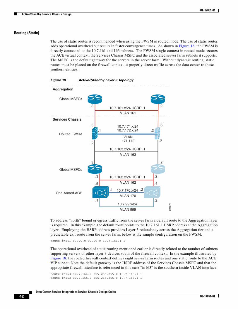
OL-17051-01 Active/Standby Service Chassis Design
Routing (Static)
The use of static routes is recommended when using the FWSM in routed mode. The use of static routes adds operational overhead but results in faster convergence times. As shown in Figure 18, the FWSM is directly connected to the 10.7.161 and 163 subnets. The FWSM single-context in routed mode secures the ACE virtual context, the Services Chassis MSFC and the associated server farm subnets it supports. The MSFC is the default gateway for the servers in the server farm. Without dynamic routing, static routes must be placed on the firewall context to properly direct traffic across the data center to these southern entities.
Figure 18 Active/Standby Layer 3 Topology
To address “north” bound or egress traffic from the server farm a default route to the Aggregation layer is required. In this example, the default route points to the 10.7.161.1 HSRP address at the Aggregation layer. Employing the HSRP address provides Layer 3 redundancy across the Aggregation tier and a predictable exit route from the server farm, below is the sample configuration on the FWSM.
route in161 0.0.0.0 0.0.0.0 10.7.161.1 1
The operational overhead of static routing mentioned earlier is directly related to the number of subnets supporting servers or other layer 3 devices south of the firewall context. In the example illustrated by Figure 18, the routed firewall context defines eight server farm routes and one static route to the ACE VIP subnet. Note the default gateway is the HSRP address of the Services Chassis MSFC and that the appropriate firewall interface is referenced in this case “in163” is the southern inside VLAN interface.
route in163 10.7.164.0 255.255.255.0 10.7.163.1 1route in163 10.7.165.0 255.255.255.0 10.7.163.1 1
VLAN 163
10.7.163.x/24 HSRP .1
VLAN 16110.7.161.x/24 HSRP .1
.3 .2
.3 .2
.3 .2
.5 .4
.1
.1 .2
.2
.5
.1 .2
.6
.5 .6VLAN
171,172
10.7.171.x/2410.7.172.x/24
VLAN 170
10.7.170.x/24
VLAN 999
10.7.99.x/24
VLAN 162
10.7.162.x/24 HSRP .1
Services Chassis
Aggregation
Global MSFCs
Global MSFCs
Routed FWSM
One-Armed ACE
2246
78
42Data Center Service Integration: Service Chassis Design Guide
OL-17051-01

OL-17051-01 Active/Standby Service Chassis Design
route in163 10.7.166.0 255.255.255.0 10.7.163.1 1route in163 10.7.167.0 255.255.255.0 10.7.163.1 1route in163 10.7.180.0 255.255.255.0 10.7.163.1 1route in163 10.7.181.0 255.255.255.0 10.7.163.1 1route in163 10.7.182.0 255.255.255.0 10.7.163.1 1route in163 10.7.183.0 255.255.255.0 10.7.163.1 1route in163 10.7.162.0 255.255.255.0 10.7.163.1 1
Note Use the show route command on the firewall context to verify its configuration and routing table.
Static routing on the firewall requires the use of static routes on the Aggregation and service chassis MSFCs. At the Aggregation layer, define the same set of routes to the firewall protected subnets with the next hop address being the northern interface address of the firewall.
ip route 10.7.162.0 255.255.255.0 10.7.161.5ip route 10.7.164.0 255.255.255.0 10.7.161.5ip route 10.7.165.0 255.255.255.0 10.7.161.5ip route 10.7.166.0 255.255.255.0 10.7.161.5ip route 10.7.167.0 255.255.255.0 10.7.161.5ip route 10.7.180.0 255.255.255.0 10.7.161.5ip route 10.7.181.0 255.255.255.0 10.7.161.5ip route 10.7.182.0 255.255.255.0 10.7.161.5ip route 10.7.183.0 255.255.255.0 10.7.161.5
The service chassis MSFC requires a single default route to the southern interface of the firewall context.
ip route 0.0.0.0 0.0.0.0 10.7.163.5
Note The use of static routes on the firewall allows the FWSM to use multiple virtual contexts, removing the single-context restriction of dynamic routing.
Routing (OSPF)
OSPF creates a very flexible and responsive Layer 3 environment but can place a high demand on the CPU and memory resources of a device. The FWSM supports OSPF routing only when configured in single-context mode. A maximum of two OSPF process maybe enabled using distinct sets of firewall interfaces.
In this design, a single OSPF firewall process establishes a neighbor relationship with the routing instances at the Aggregation layer and in the Services Chassis'. The firewall route process advertises via the north and south bound interfaces propagating the routes between the Aggregation and services chassis routing entities. The SPF timers are complementary to its neighbors and authentication is required to prevent route poisoning.
router ospf 7 network 10.7.161.0 255.255.255.0 area 71 network 10.7.163.0 255.255.255.0 area 71 area 71 authentication message-digest area 71 nssa default-information-originate router-id 9.9.9.1 timers spf 1 3 log-adj-changes redistribute connected metric 100 subnets default-information originate metric 1!
43Data Center Service Integration: Service Chassis Design Guide
OL-17051-01

OL-17051-01 Active/Standby Service Chassis Design
Note Use router IDs to simplify logging and troubleshooting.
The use of OSPF on the firewall requires that each VLAN interface participating in the dynamic routing protocol have parameters consistent with other routers in the network. As a result of testing, it was determined that OSPF hello and dead intervals be set to 1 and 3 seconds. These should match the Aggregation layer and local service switch neighbor timing parameters. In addition, it is a best practice to provide route authentication security. Below find the “north” and “south” FWSM interfaces with OSPF enabled:
interface Vlan161 description <to aggregation layer> nameif in161 security-level 0 ip address 10.7.161.5 255.255.255.0 standby 10.7.161.6 ospf cost 10 ospf hello-interval 1 ospf dead-interval 3 ospf message-digest-key 1 md5 <removed> ospf authentication message-digest!interface Vlan163 description <to ss1 msfc> nameif in163 security-level 100 ip address 10.7.163.5 255.255.255.0 standby 10.7.163.4 ospf cost 10 ospf hello-interval 1 ospf dead-interval 3 ospf message-digest-key 1 md5 <removed> ospf authentication message-digest
Note Remove the ospf commands from the VLAN interfaces when leveraging static routing on the firewall.
Multicast
The FWSM supports multicast routing up to a maximum of eight interfaces. In this design, the firewall context has multicast routing enabled which automatically enables PIM sparse mode and IGMP on both the north and south interfaces. To enable multicast routing support on the firewall context issue the following command:
multicast-routing
The Rendezvous Point (RP) address must be statically configured on the firewall context. The FWSM does not support Auto-RP or PIM BSR for RP discovery. In this topology, the RP is a located at the core and is defined as a Loopback address. Create a static mapping to the RP as follows:
pim rp-address 10.7.23.1
Note If multicast routing is required through the FWSM in a routed mode, OSPF should be used for dynamic routing. Static routing pointing to an HSRP address is not a supported configuration with FWSM version 3.2. Alternatively, a transparent-mode FWSM configuration could be considered for service deployment.
44Data Center Service Integration: Service Chassis Design Guide
OL-17051-01
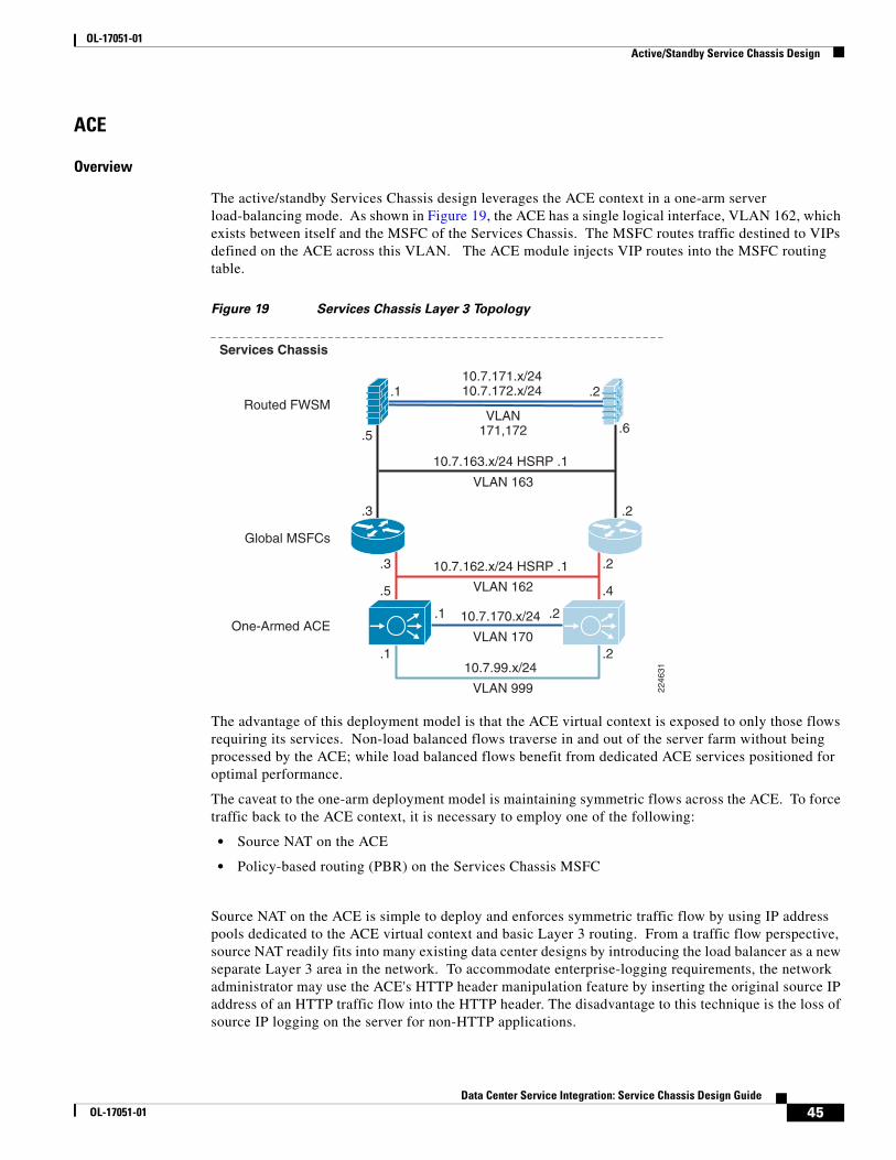
OL-17051-01 Active/Standby Service Chassis Design
ACE
Overview
The active/standby Services Chassis design leverages the ACE context in a one-arm server load-balancing mode. As shown in Figure 19, the ACE has a single logical interface, VLAN 162, which exists between itself and the MSFC of the Services Chassis. The MSFC routes traffic destined to VIPs defined on the ACE across this VLAN. The ACE module injects VIP routes into the MSFC routing table.
Figure 19 Services Chassis Layer 3 Topology
The advantage of this deployment model is that the ACE virtual context is exposed to only those flows requiring its services. Non-load balanced flows traverse in and out of the server farm without being processed by the ACE; while load balanced flows benefit from dedicated ACE services positioned for optimal performance.
The caveat to the one-arm deployment model is maintaining symmetric flows across the ACE. To force traffic back to the ACE context, it is necessary to employ one of the following:
• Source NAT on the ACE
• Policy-based routing (PBR) on the Services Chassis MSFC
Source NAT on the ACE is simple to deploy and enforces symmetric traffic flow by using IP address pools dedicated to the ACE virtual context and basic Layer 3 routing. From a traffic flow perspective, source NAT readily fits into many existing data center designs by introducing the load balancer as a new separate Layer 3 area in the network. To accommodate enterprise-logging requirements, the network administrator may use the ACE's HTTP header manipulation feature by inserting the original source IP address of an HTTP traffic flow into the HTTP header. The disadvantage to this technique is the loss of source IP logging on the server for non-HTTP applications.
VLAN 163
10.7.163.x/24 HSRP .1
.3 .2
.3 .2
.5 .4
.1
.1 .2
.2
.1 .2
.5 .6VLAN
171,172
10.7.171.x/2410.7.172.x/24
VLAN 170
10.7.170.x/24
VLAN 999
10.7.99.x/24
VLAN 162
10.7.162.x/24 HSRP .1
Services Chassis
Global MSFCs
Routed FWSM
One-Armed ACE
2246
31
45Data Center Service Integration: Service Chassis Design Guide
OL-17051-01

OL-17051-01 Active/Standby Service Chassis Design
PBR) leverages advanced routing rules to direct traffic back to the ACE virtual context. PBR requires that the network administrator define route-maps and apply them to the appropriate server facing interfaces on the Services Chassis. These route maps create symmetric traffic patterns by redirecting returning flows from the server farm back to the ACE context.
The remainder of this section details the ACE active/standby one-arm design using source NAT.
Catalyst 6500 IOS Configuration
The ACE service module physically resides in the Cisco Catalyst 6500 switching platform. To leverage this integrated service the following tasks must be completed:
Step 1 Create the VLANs to support traffic ingress and egress from the ACE, and fault tolerance traffic between modules.
Step 2 Allow the ACE to leverage the autostate messaging capabilities of the 6500-supervisor engine. Autostate reporting by the supervisor indicates the status of the physical interfaces of the VLANs associated with the ACE module in the switch, expediting the failover process.
Step 3 Allow multiple VLAN interfaces (SVI) to be associated with the ACE module. In this example, VLAN 146 the management VLAN and VLAN 162 each have a SVI and as such it is required.
Step 4 Assign the VLANs to the SVCLC VLAN groups. This includes production and fault tolerant VLANs.
Step 5 Assign the VLAN groups to the associated ACE service module.
The following example highlights the tasks defined above:
vlan 146vlan 162vlan 170vlan 999firewall vlan group 1 146svclc autostatesvclc multiple-vlan-interfacessvclc module 5 vlan-group 1,52,162,999,svclc vlan-group 52 170svclc vlan-group 162 162svclc vlan-group 999 999
Beyond basic communication between the ACE and the Catalyst switching fabric, the active/standby Services Chassis design will leverage the Cisco IP Service Level Agreements (SLAs) monitoring features. Using IP SLAs provides more predictable and deterministic traffic patterns, aligning ingress and egress traffic to the data center with available network services. In this scenario, the IP SLA functionality will allow network administrators to migrate the HSRP active interface for the ACE and load-balance server farm VLANs between Services Chassis' MSFCs based on the health of the ACE module, specifically, the availability of the IP address associated with the local VLAN interface of the one-arm ACE virtual context. If the local ACE virtual context VLAN interface is "down" or "unavailable", the default gateway for the ACE one-arm contexts and the server farms it supports will move to the standby Services Chassis MSFC which preempts the currently active HSRP groups. This network operation optimizes traffic flow in and out of the data center.
To configure IP SLA, perform the following configurations on the “active” or primary Services Chassis::
Step 1 Define the SLA.
Step 2 Create a track object.
Step 3 Enable HSRP tracking.
46Data Center Service Integration: Service Chassis Design Guide
OL-17051-01

OL-17051-01 Active/Standby Service Chassis Design
The network administrator will define the IP SLA to probe the ACE VLAN interface. In this example, the IP SLA uses an ICMP probe. The SLA probe interval and dead timer are set, the timeout uses milliseconds and the frequency is in seconds. With this configuration, the network SLA status will adjust within one second. Verify the configuration with the show ip sla monitor configuration command:
• ip sla monitor 1
• type echo protocol ipIcmpEcho 10.7.162.5 source-ipaddr 10.7.162.3
• timeout 1000
• frequency 3
• ip sla monitor schedule 1 life forever start-time now
To enable or start the SLA, it must be scheduled. The final command in the above example initializes the probe immediately and it will execute indefinitely, barring any supervisor failure.
Note The configuration of IP SLA is suitable for the Services Chassis deployment , but note that there are many advanced parameters not addressed in this document. For more information on IP SLA, refer to http://www.cisco.com/en/US/tech/tk920/tsd_technology_support_sub-protocol_home.html.
A tracked object is a software construct directly coupled to the state of the IP SLA monitor. Using the show ip sla monitor statistics command, the network administrator may verify the state of the SLA. In this example, ACE VLAN interface is available, responding to the ICMP probe.
show ip sla monitor statistics Round trip time (RTT) Index 1 Latest RTT: 1 msLatest operation start time: 14:48:34.201 EST Tue Jun 17 2008Latest operation return code: OKNumber of successes: 478Number of failures: 0Operation time to live: Forever
The track object references the SLA probe. The configuration below state that track object “1” will reflect the return code from the SLA operation. The delay down and up allows for 10 seconds of convergence prior to the HSRP group being notified of a state change. This up and down delay can be set as low as one second, but in an effort to create a more stable data center, it is best to allow some delay to dampen a flapping condition.
track 1 rtr 1 delay down 10 up 10
The tracking object is associated to all HSRP groups that rely on the ACE virtual context for services. In this design, there are two server farm VLANs and the one-arm interface VLAN of the ACE. Moving the default gateway of each of these devices to the secondary Services Chassis when the primary ACE fails optimizes traffic flow into and out of the Services Chassis layer. Below is the HSRP configuration for the one-arm ACE VLAN interface. Note the tracked object upon failure will reduce the HSRP priority by 15, allowing the standby HSRP device to preempt the active HSRP peer.
interface Vlan162 ip address 10.7.162.3 255.255.255.0 ip pim sparse-mode ip igmp version 3 standby 1 ip 10.7.162.1 standby 1 timers 1 3 standby 1 priority 20 standby 1 preempt delay minimum 180 standby 1 authentication c1sc0
47Data Center Service Integration: Service Chassis Design Guide
OL-17051-01

OL-17051-01 Active/Standby Service Chassis Design
standby 1 name hsrp162 standby 1 track 1 decrement 15end
The show track and show standby vlan commands can confirm the proper configuration of this availability feature. Below is an example of the show track output.
show track 1 Track 1 Response Time Reporter 1 state State is Down 11 changes, last change 00:05:29 Delay up 10 secs, down 10 secs Latest operation return code: Timeout Tracked by: HSRP Vlan162 1 HSRP Vlan180 1 HSRP Vlan181 1
The failure of the tracked ACE interface forces an HSRP convergence aligning the server farm default gateways to the active ACE virtual context and its default gateway the Services Chassis HSRP address on the MSFC. Creating further service alignment via dynamic routing and ACE RHI is discussed in the “Route Health Injection (RHI)” section on page 54.
Fault Tolerance Implementation
To maintain a highly available network service, the ACE is configured in an active/standby model. There are actually two fundamental approaches to achieve this end goal:
1. Create active/standby physical ACE devices.
2. Virtualize the active/standby physical pairs to support multiple virtual ACE contexts.
The first method is the traditional network services deployment model. A pair of redundant network service devices is deployed into the data center fabric. Physical redundancy addresses the enterprise high availability requirements but does not address the need for enterprise service flexibility.
Enterprise service flexibility is the ability to quickly address new applications or application requirements within the data center. Physical redundancy in and of itself does not provide service flexibility. Physical service device redundancy is restrictive, forcing future application deployments to adhere to the original deployment model that may or may not meet the future needs of the enterprise.
Virtualized active/standby ACE contexts address both high availability and service flexibility in the data center. Physically redundant devices can be provisioned with multiple virtual contexts. The deployment of these virtual contexts can vary from routed, bridged or one-arm modes. This allows for future growth and changing application requirements while simultaneously meeting the enterprise high availability needs.
Note The base ACE service module supports five virtualized contexts and can be licensed to support up to 250 contexts.
As stated earlier, the ACE supports both approaches. In this design, the redundant pair of ACE modules are virtualized. ACE virtualization means that there will be an Admin context and one or more virtual ACE contexts. The Admin context defines the fundamental fault tolerant configuration of the ACE and is the primary management construct of the module.
48Data Center Service Integration: Service Chassis Design Guide
OL-17051-01

OL-17051-01 Active/Standby Service Chassis Design
Fault Tolerance Configuration (Admin Context)
The following section details the Admin context configuration used in the active/standby Services Chassis design. As shown in Figure 19, the ACE modules housed in the Services Chassis have a single logical connection via VLAN 170. From a physical perspective, VLAN 170 is configured on an EtherChannel ISL dedicated to fault tolerant traffic that directly connects the two Services Chassis. The fault tolerant interface configuration defines the local and peer ACE interface parameters.
ft interface vlan 170 ip address 10.7.170.1 255.255.255.0 peer ip address 10.7.170.2 255.255.255.0 no shutdown
It is necessary to define the fault tolerant peer and the associated parameters for peer communications. In this design, the fault tolerant interface is VLAN 170 and the unit heartbeat details are set to 100 milliseconds with a failure count of 10 to consider the peer inactive. This effectively means there will be a one second delay in failure detection. It should be noted these heartbeat values are set to their lowest configurable value.
ft peer 1 heartbeat interval 100 heartbeat count 10 ft-interface vlan 170 query-interface vlan 999
Figure 20 below is sniffers capture of the ACE fault tolerant VLAN and the UDP heartbeats occurring between ACE peers.
Figure 20 Capture of ACE Heartbeats
In addition to the fault tolerant interface, the design employs a query interface. The query interface is a redundant failure detection mechanism employed by the standby peer. The query interface allows the standby peer to test the status of the primary ACE via ICMP if the fault tolerant link is lost. This allows the standby peer to more accurately assess the state of the primary ACE module and avoid creating an active/active virtual context condition.
Note The query VLAN is not present on the ISL between Services Chassis. Sharing the fault tolerant link physical path would defeat the purpose of this backup high availability feature.
Note Query interface tests will delay failover until their completion; if it is determined failover is necessary.
49Data Center Service Integration: Service Chassis Design Guide
OL-17051-01
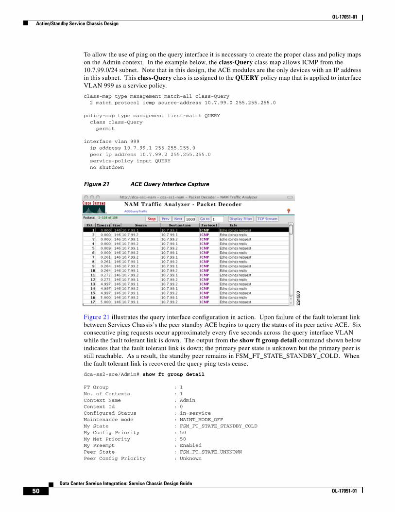
OL-17051-01 Active/Standby Service Chassis Design
To allow the use of ping on the query interface it is necessary to create the proper class and policy maps on the Admin context. In the example below, the class-Query class map allows ICMP from the 10.7.99.0/24 subnet. Note that in this design, the ACE modules are the only devices with an IP address in this subnet. This class-Query class is assigned to the QUERY policy map that is applied to interface VLAN 999 as a service policy.
class-map type management match-all class-Query 2 match protocol icmp source-address 10.7.99.0 255.255.255.0
policy-map type management first-match QUERY class class-Query permit
interface vlan 999 ip address 10.7.99.1 255.255.255.0 peer ip address 10.7.99.2 255.255.255.0 service-policy input QUERY no shutdown
Figure 21 ACE Query Interface Capture
Figure 21 illustrates the query interface configuration in action. Upon failure of the fault tolerant link between Services Chassis’s the peer standby ACE begins to query the status of its peer active ACE. Six consecutive ping requests occur approximately every five seconds across the query interface VLAN while the fault tolerant link is down. The output from the show ft group detail command shown below indicates that the fault tolerant link is down; the primary peer state is unknown but the primary peer is still reachable. As a result, the standby peer remains in FSM_FT_STATE_STANDBY_COLD. When the fault tolerant link is recovered the query ping tests cease.
dca-ss2-ace/Admin# show ft group detail
FT Group : 1No. of Contexts : 1Context Name : AdminContext Id : 0Configured Status : in-serviceMaintenance mode : MAINT_MODE_OFFMy State : FSM_FT_STATE_STANDBY_COLDMy Config Priority : 50My Net Priority : 50My Preempt : EnabledPeer State : FSM_FT_STATE_UNKNOWNPeer Config Priority : Unknown
50Data Center Service Integration: Service Chassis Design Guide
OL-17051-01
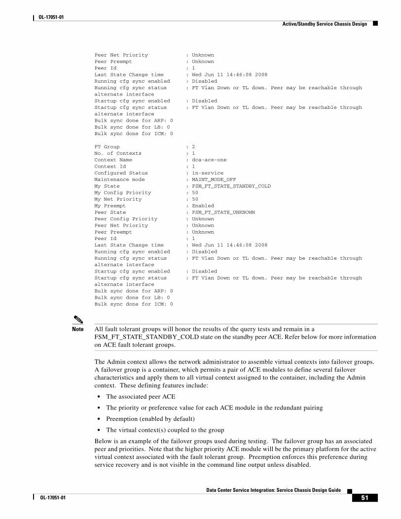
OL-17051-01 Active/Standby Service Chassis Design
Peer Net Priority : UnknownPeer Preempt : UnknownPeer Id : 1Last State Change time : Wed Jun 11 14:46:08 2008Running cfg sync enabled : DisabledRunning cfg sync status : FT Vlan Down or TL down. Peer may be reachable through alternate interfaceStartup cfg sync enabled : DisabledStartup cfg sync status : FT Vlan Down or TL down. Peer may be reachable through alternate interfaceBulk sync done for ARP: 0Bulk sync done for LB: 0Bulk sync done for ICM: 0
FT Group : 2No. of Contexts : 1Context Name : dca-ace-oneContext Id : 1Configured Status : in-serviceMaintenance mode : MAINT_MODE_OFFMy State : FSM_FT_STATE_STANDBY_COLDMy Config Priority : 50My Net Priority : 50My Preempt : EnabledPeer State : FSM_FT_STATE_UNKNOWNPeer Config Priority : UnknownPeer Net Priority : UnknownPeer Preempt : UnknownPeer Id : 1Last State Change time : Wed Jun 11 14:46:08 2008Running cfg sync enabled : DisabledRunning cfg sync status : FT Vlan Down or TL down. Peer may be reachable through alternate interfaceStartup cfg sync enabled : DisabledStartup cfg sync status : FT Vlan Down or TL down. Peer may be reachable through alternate interfaceBulk sync done for ARP: 0Bulk sync done for LB: 0Bulk sync done for ICM: 0
Note All fault tolerant groups will honor the results of the query tests and remain in a FSM_FT_STATE_STANDBY_COLD state on the standby peer ACE. Refer below for more information on ACE fault tolerant groups.
The Admin context allows the network administrator to assemble virtual contexts into failover groups. A failover group is a container, which permits a pair of ACE modules to define several failover characteristics and apply them to all virtual context assigned to the container, including the Admin context. These defining features include:
• The associated peer ACE
• The priority or preference value for each ACE module in the redundant pairing
• Preemption (enabled by default)
• The virtual context(s) coupled to the group
Below is an example of the failover groups used during testing. The failover group has an associated peer and priorities. Note that the higher priority ACE module will be the primary platform for the active virtual context associated with the fault tolerant group. Preemption enforces this preference during service recovery and is not visible in the command line output unless disabled.
51Data Center Service Integration: Service Chassis Design Guide
OL-17051-01

OL-17051-01 Active/Standby Service Chassis Design
ft group 1 peer 1 priority 150 peer priority 50 associate-context Admin inservice
The creation of the one-arm ACE virtual context assigns the appropriate VLAN interfaces to the virtual device. This is a sample of the configuration. Interface VLAN 162 is the “stick” VLAN and directly connects the ACE to the Services Chassis MSFC.
context dca-ace-one description ** ACE one-arm mode ** allocate-interface vlan 162
ft group 2 peer 1 priority 150 peer priority 50 associate-context dca-ace-one inservice
The tracking features of the ACE can decrement the failover group priority value allowing intelligent and conditional graceful failover between modules. The fault tracking features in this design will be documented under the ACE Virtual Context Configuration section, but it is important to understand that the priority or module preference definition is found under the failover group construct.
Note ACE features configuration synchronization between peers. This means only a limited set of interface and fault tolerant configuration is necessary on the peer ACE to match the primary ACE configuration through this automated feature. Configuration synchronization applies to all contexts including the Admin context.
Context Configuration
The one-arm deployment model optimizes traffic flow across the server farm by selectively directing traffic requiring ACE services; be they load balancing, security, or application specific. To create an efficient and highly available ACE service, the one-arm virtual context will employ the following key features:
• Source NAT
• Route Health Injection (RHI)
• Object Tracking
This portion of the document will explore the use of these elements in the active/standby one-arm ACE context to provide a highly available service. The configuration are synchronized between the active and standby ACE modules.
Note This document does not describe the ACE configuration basics. For more information on the ACE go to the following URLhttp://www.cisco.com/en/US/docs/interfaces_modules/services_modules/ace/v3.00_A2/configuration/quick/guide/getstart.html
52Data Center Service Integration: Service Chassis Design Guide
OL-17051-01

OL-17051-01 Active/Standby Service Chassis Design
Source NAT
In this design, the virtual context leverages a single VLAN interface namely VLAN 162. The active ACE context interface is given an IP address, as is the peer interface. In addition, the interface has an alias IP address defined that is “shared” between the active and standby virtual contexts. The alias IP address provides a consistent Layer 3 identity for the active virtual context. The alias IP address will migrate across physical modules when a failover event occurs. The example below highlights the Layer 3 interface configuration:
interface vlan 162 ip address 10.7.162.5 255.255.255.0 alias 10.7.162.6 255.255.255.0 peer ip address 10.7.162.4 255.255.255.0
The ACE implicitly denies all incoming traffic. The network administrator must define the applications and or traffic flows permitted to cross the ACE interface. Access control lists (ACLs) enforce the security policy. Refining these permissions optimizes the resources of the ACE and provides a more secure environment. The following is a sample access list:
access-list ALLOW_TRAFFIC line 16 extended permit ip any any
Note The ACLs in this example are not recommended as a best practice but are simply in place to illustrate the process. ACLs must be tailored to meet the application and security requirements of each data center environment.
The access-list is “grouped “ and may be applied individually to all relevant interfaces or it may be applied globally. In a one-arm design, production traffic in and out of the ACE leverages a single interface. In this example, the access group is applied to the VLAN 162 interface. Note that this requires the network administrator to define an ingress and egress security policy.
interface vlan 162access-group input ALLOW_TRAFFICaccess-group output ALLOW_TRAFFIC
Source NAT allows the symmetric flow of traffic across the virtual one-arm context. On the VLAN interface, it is necessary to define a NAT pool. In the example below, interface VLAN 162 contains NAT pool “1”. NAT pool “1” employs dynamic Port Address Translation (PAT) to provide greater NAT address scale.
interface vlan 162 nat-pool 1 10.7.162.150 10.7.162.160 netmask 255.255.255.0 pat service-policy input aggregate-slb-policy
To use the interface NAT pool configuration, the network administrator must associate the pool with a service policy. As shown above, the aggregate-slb-policy is the only policy assigned to the interface. The following commands define the aggregate-slb-policy service policy:
policy-map multi-match aggregate-slb-policy class VIP_180 loadbalance vip inservice loadbalance policy pm-slb loadbalance vip icmp-reply loadbalance vip advertise active nat dynamic 1 vlan 162
class-map match-all VIP_180 description *VIP for VLAN 180* 2 match virtual-address 10.7.162.100 any
53Data Center Service Integration: Service Chassis Design Guide
OL-17051-01

OL-17051-01 Active/Standby Service Chassis Design
policy-map type loadbalance first-match pm-slb class class-default serverfarm sf_180
The aggregate-slb-policy service policy has a single class that defines the virtual IP address (VIP) of the server farm. Traffic destined to this VIP will be load-balanced according to the policy described by the pm-slb configuration. The VIP will respond to ICMP requests and leverage NAT pool “1” delineated under the 162 VLAN interface.
Route Health Injection (RHI)
RHI allows the active ACE context to advertise the VIP as a host route (/32 netmask). RHI injects the host route into the local Services Chassis MSFC. The metric associated with this route is adjustable via the ACE. The VIP route can then be redistributed into the IGP via a route map on the Services Chassis. In the active/standby Services Chassis design, OSPF will redistribute the route. An RHI implementation requires the network administrator to make the necessary configurations on the ACE virtual context and the local Services Chassis MSFC.
Note RHI is relevant when combined with a dynamic routing protocol which redistributes the static ACE VIP host routes. In this design, the FWSM and MSFC each employ OSPF and therefore advertise the RHI route.
On the virtual ACE context, enable the VIP route advertisement under the service policy map. In the following example, the aggregate-slb-policy implements RHI. Note that the optional keyword “active” is present. The active command only advertises the VIP if the ACE detects a healthy server farm state. This creates a direct connection between the Layer 3 routing in the network and the health of the application.
policy-map multi-match aggregate-slb-policy class VIP_180 loadbalance vip inservice loadbalance policy pm-slb loadbalance vip icmp-replyloadbalance vip advertise active nat dynamic 1 vlan 162
On the Services Chassis MSFC, the ACE injected route appears as a static. The following is an output from the show ip route | include 10.7.162.100 command . Note that 10.7.162.100 is the VIP address being advertised.
show ip route | include 10.7.162.100S 10.7.162.100/32 [77/0] via 10.7.162.6, Vlan162
One of the goals of this architecture validation is to create predictable traffic patterns within a data center leveraging Services Chassis. This Active-Standby design optimizes traffic flow through one “active” Services Chassis. To accomplish this goal, use OSPF route costs as described earlier to prefer one services switch over the other, or use a combination or RHI and OSPF metric variation. RHI will remove the equal cost paths to the VIP via the Services Chassis MSFC. Simplifying the data center traffic patterns. Without RHI or OSPF route costs, the active FWSM context will distribute incoming data center load across the two Services Chassis MSFCs destined to the VIP. This can be seen in the following show route command on the FWSM.
O 10.7.162.0 255.255.255.0 [110/20] via 10.7.163.3, 0:00:07, in163 [110/20] via 10.7.163.2, 0:00:07, in163
54Data Center Service Integration: Service Chassis Design Guide
OL-17051-01

OL-17051-01 Active/Standby Service Chassis Design
With RHI, the FWSM will have a single path to the ACE VIP via the MSFC on the active Services Chassis. Below is the output of the FWSM show route command, with ACE RHI and route-map redistribution into OSPF. The route indicates a single Layer 3 forwarding path employing the active Services Chassis interface to the FWSM.
O N1 10.7.162.100 255.255.255.255 [110/40] via 10.7.163.3, 0:00:04, in163
The active service switch has the following routing table configuration for the 10.7.162.x subnet.
C 10.7.162.0/24 is directly connected, Vlan162S 10.7.162.100/32 [77/0] via 10.7.162.6, Vlan162
The secondary services switch does not have a host route to the VIP as the local ACE is not active. The following show ip route command sample confirms this detail.
C 10.7.162.0/24 is directly connected, Vlan162
In order to redistribute the RHI route throughout the OSPF area, the network administrator should perform the following configurations on each of the Services Chassis MSFCs:
Step 1 Create an access list referencing the VIP address on the ACE (see access list 10 below).
Step 2 Create an access list defining the redistributable connected subnets (see access list 100) Notice that the VLAN 162, the one-arm VLAN, is not advertised nor the 172.x.x.x management subnet.
Step 3 Create a route-map that uses the VIP access list to match the proper static routes. It is recommended to use the metric-type of 1 (see RHI-MAP).
Step 4 Create a route-map that defines the connected subnets to be advertised (see OSPF route map).
Step 5 Redistribute the static and connected routes into OSPF via the associated route-maps.
Caution Do not redistribute the next hop subnet to reach the ACE VIP subnet; otherwise, OSPF will use ECMP to reach the next hop to the VIP.
The following example was taken from the Services Chassis configuration:
router ospf 7 router-id 4.4.4.1 log-adjacency-changes auto-cost reference-bandwidth 10000 area 71 authentication message-digest area 71 nssa timers throttle spf 10 100 5000 timers throttle lsa all 10 100 5000 redistribute connected metric 10 metric-type 1 subnets route-map OSPF redistribute static subnets route-map RHI-MAP passive-interface default no passive-interface Vlan163 network 10.7.163.0 0.0.0.255 area 71!access-list 10 permit 10.7.162.100access-list 100 deny ip 10.7.162.0 0.0.0.255 anyaccess-list 100 deny ip 172.0.0.0 0.255.255.255 anyaccess-list 100 permit ip any anyroute-map OSPF permit 10 match ip address 100!route-map RHI-MAP permit 10
55Data Center Service Integration: Service Chassis Design Guide
OL-17051-01

OL-17051-01 Active/Standby Service Chassis Design
match ip address 10 set metric-type type-1!
Note The route map construct allows the network administrator to modify the characteristics of the redistributed routes such as the metric and metric-type.
A failure event where the secondary ACE becomes active will result in the advertising of the RHI route from the secondary Services Chassis. Allowing traffic from the active FWSM context to forward directly to the Services Chassis hosting the active ACE context. This sample output taken from the standby services switch after an ACE failure, shows the newly injected RHI static route and the FWSM route via the secondary Services Chassis with the active ACE.
C 10.7.162.0/24 is directly connected, Vlan162S 10.7.162.100/32 [77/0] via 10.7.162.6, Vlan162
The FWSM references this new path, confirming the efficient coupling of a dynamic routing protocol and RHI.
O N1 10.7.162.100 255.255.255.255 [110/30] via 10.7.163.2, 0:00:04, in163
Object Tracking
Object tracking is a high availability feature on the ACE to implement or influence ACE failover when the status of other hosts, interfaces, or gateways change. The active/standby service chassis design employs interface and host tracking. HSRP tracking was deemed inappropriate for this design for several reasons that are outlined below.
Tracking the local HSRP group does not account for a specific failure scenario, Services Chassis isolation. Figure 22 illustrates the isolation of the Services Chassis. In this example, the links to the Aggregation layer have failed. The only remaining external physical interface is the EtherChannel dedicated to fault tolerant service module traffic. As a result, all of the HSRP groups defined in each of the Services Chassis become active.
56Data Center Service Integration: Service Chassis Design Guide
OL-17051-01

OL-17051-01 Active/Standby Service Chassis Design
Figure 22 Services Chassis Isolation Example
Enabling HSRP tracking does not remedy this situation as HSRP tracking only reduces the priority of the HSRP group. Without communication between the HSRP peering routers, the standby cannot preempt the primary “isolated” member. The following HSRP output summarizes this event.
show standby vlan 162 all Vlan162 - Group 1 State is Active 8 state changes, last state change 1w1d Virtual IP address is 10.7.162.1 Active virtual MAC address is 0000.0c07.ac01 Local virtual MAC address is 0000.0c07.ac01 (v1 default) Hello time 1 sec, hold time 3 sec Next hello sent in 0.320 secs Authentication text "c1sc0" Preemption enabled, delay min 180 secs Active router is localStandby router is unknownPriority 0 (configured 20) Track interface Port-channel111 state Down decrement 10 Track interface Port-channel122 state Down decrement 10 IP redundancy name is "hsrp162" (cfgd)
Fault tolerant HSRP tracking on the ACE would not detect this failure, as the local HSRP GROUP is considered active by the MSFC. The ACE virtual context view shown below of the failure event confirms that the current active ACE context will not converge, resulting in the blackholing of traffic. The secondary ACE, which has active egress traffic paths, will not preempt the active ACE.
VLAN 163
10.7.163.x/24 HSRP .1
VLAN 16110.7.161.x/24 HSRP .1
.3 .2
.3 .2
.3 .2
.5 .4
.1
.1 .2
.2
.5
.1 .2
.6
.5 .6VLAN
171,172
10.7.171.x/2410.7.172.x/24
VLAN 170
10.7.170.x/24
VLAN 999
10.7.99.x/24
VLAN 162
10.7.162.x/24 HSRP .1
Services Chassis
Aggregation
Global MSFCs
Global MSFCs
Routed FWSM
One-Armed ACE
2246
32
57Data Center Service Integration: Service Chassis Design Guide
OL-17051-01
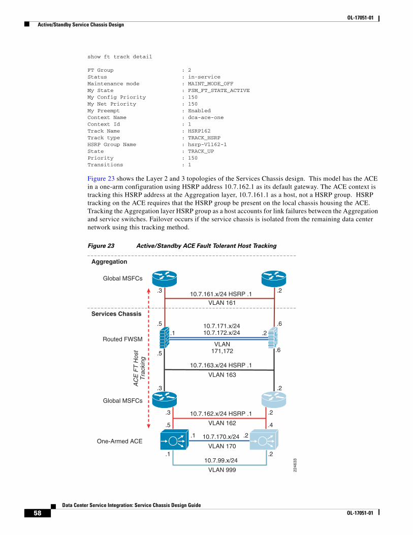
OL-17051-01 Active/Standby Service Chassis Design
show ft track detail
FT Group : 2Status : in-serviceMaintenance mode : MAINT_MODE_OFFMy State : FSM_FT_STATE_ACTIVEMy Config Priority : 150My Net Priority : 150My Preempt : EnabledContext Name : dca-ace-oneContext Id : 1Track Name : HSRP162Track type : TRACK_HSRPHSRP Group Name : hsrp-Vl162-1State : TRACK_UP Priority : 150Transitions : 1
Figure 23 shows the Layer 2 and 3 topologies of the Services Chassis design. This model has the ACE in a one-arm configuration using HSRP address 10.7.162.1 as its default gateway. The ACE context is tracking this HSRP address at the Aggregation layer, 10.7.161.1 as a host, not a HSRP group. HSRP tracking on the ACE requires that the HSRP group be present on the local chassis housing the ACE. Tracking the Aggregation layer HSRP group as a host accounts for link failures between the Aggregation and service switches. Failover occurs if the service chassis is isolated from the remaining data center network using this tracking method.
Figure 23 Active/Standby ACE Fault Tolerant Host Tracking
VLAN 163
10.7.163.x/24 HSRP .1
VLAN 16110.7.161.x/24 HSRP .1
.3 .2
.3 .2
.3 .2
.5 .4
.1
.1 .2
.2
.5
.1 .2
.6
.5
AC
E F
T H
ost
Tra
ckin
g
.6VLAN
171,172
10.7.171.x/2410.7.172.x/24
VLAN 170
10.7.170.x/24
VLAN 999
10.7.99.x/24
VLAN 162
10.7.162.x/24 HSRP .1
Services Chassis
Aggregation
Global MSFCs
Global MSFCs
Routed FWSM
One-Armed ACE
2246
33
58Data Center Service Integration: Service Chassis Design Guide
OL-17051-01

OL-17051-01 Active/Standby Service Chassis Design
Below is a snippet of the fault tolerant host-tracking configuration on the virtual one-arm ACE context. This configuration uses a ping probe, namely TrackHostProbe, to monitor the Aggregation layer HSRP address. The fault tolerant priority settings decrement when a failure condition is met. The total context priority is set in the failover group configuration of the Admin context. In this example, the priority for the primary active context is 150; failure of the host-tracking probe reduces the priority by 150 allowing the secondary to preempt the primary. See previous section for more configuration information.
ft track host HSRP161 track-host 10.7.161.1 probe TrackHostProbe priority 150 peer priority 50
probe icmp TrackHostProbe description this is a ping probe interval 2 faildetect 1 passdetect interval 2 passdetect count 1 receive 1
The network capture in Figure 24 verifies that the ping probe is working as scheduled and is leveraging the local IP address of the virtual context not the “share” alias IP address.
Figure 24 ACE Fault Tolerant Probe Capture
To verify the state of the tracking, use the show ft track detail command. In this scenario with the Aggregation links broken, the primary ACE is in a standby state due to the “down” state of the host being tracked.
show ft track detail
FT Group : 2Status : in-serviceMaintenance mode : MAINT_MODE_OFFMy State : FSM_FT_STATE_STANDBY_HOTMy Config Priority : 150My Net Priority : 0My Preempt : EnabledContext Name : dca-ace-oneContext Id : 1Track Name : HSRP161Track type : TRACK_HOSTHost IP Address : 10.7.161.1State : TRACK_DOWNPriority : 150Transitions : 1Probe count : 1Probes down : 1Probe name : TrackHostProbe
59Data Center Service Integration: Service Chassis Design Guide
OL-17051-01
OL-17051-01 Active/Standby Service Chassis Design
State : TRACK_DOWNPriority : 0Transitions : 1
Access Layer
Overview
The data center Access layer design can vary depending on the type of servers in use and the access switch placement in the row or rack. End-of-row (EoR) and middle-of-row (MoR) designs are common when using a larger switch such as a Cisco Catalyst 6500 to provide access ports for several racks full of servers. Also popular are top-of-rack (ToR) designs, where each server rack (or sometimes pair of server racks) has a smaller 1 or 2 Rack Unit (RU) switch installed to terminate server connections at the edge. In addition, blade server chassis are sometimes used, which can have integrated switches, or pass-through modules that allow them to leverage a ToR or EoR/MoR access switch.
The Active-Standby Services Chassis model was validated using two of the more common network topologies for the Access layer. The topologies are referred to as the looped triangle and looped square . “Looped” refers to the fact that with a Layer 2 access design, the server VLANs each form a Spanning Tree loop with the access switch uplinks in conjunction with the Aggregation layer. The looped triangle design is the most common, and is often used in EoR or MoR configurations. The looped square sacrifices some stability and has a slightly higher convergence time due to the additional switch hop in the STP loop. However, the looped square design reduces Aggregation port count requirements by 50%; therefore, it is popular in ToR environments where there is typically a greater number of smaller Access layer switches. Figure 25 illustrates the looped triangle and looped square designs.
60Data Center Service Integration: Service Chassis Design Guide
OL-17051-01

OL-17051-01 Active/Standby Service Chassis Design
Figure 25 Figure 26 Looped Triangle and Looped Square
The Active-Standby Services Chassis model was validated exclusively with the use of Layer 2 looped access topologies. In order to span the server farm VLANs from the Access layer over into the Services Chassis, a looped design must be used to prevent traffic from using the Services Chassis as a backup transit path in the event of an Access-to-Aggregation link failure. Looped designs are also becoming more prevalent in the data center due to the requirement of supporting physical and virtual movement of servers between racks and pods, which may be hosted by different Access switches.
Features
Portfast
Spanning Tree Portfast is a Cisco Spanning Tree enhancement that allows end nodes to become active on a switched port and begin sending and receiving traffic without waiting for the switch to run a Spanning Tree calculation. Portfast should be used strictly on Access layer ports providing server connectivity, not the uplink connections to the Aggregation.
BPDU Guard
Spanning Tree BPDU Guard works in conjunction with Portfast, and should be enabled on the same ports. The ports facing servers or other end nodes that are not bridges or switches should not be producing any BPDUs. If a BPDU is received on a port with BPDU Guard enabled, the switch will move
Core
Aggregation
EnterpriseNetwork
Access
Services
2246
27LoopedTriangle
LoopedSquare
61Data Center Service Integration: Service Chassis Design Guide
OL-17051-01

OL-17051-01 Active/Active Service Chassis Design
the port into an error-disabled state and will not forward traffic. This state must me manually resolved by a system administrator. BPDU Guard prevents against inadvertent connection of a rogue switch to a data center Access layer port, or accidental cross-connection between switches.
Unidirectional Link Detection (UDLD)
The Cisco-proprietary UDLD protocol allows devices connected through fiber-optic or copper (for example, Category 5 cabling) Ethernet cables connected to LAN ports to monitor the physical configuration of the cables and detect when a unidirectional link exists. When a unidirectional link is detected, UDLD shuts down the affected LAN port and alerts the user. Unidirectional links can cause a variety of problems, including spanning tree topology loops. UDLD should be enabled globally on all switches in the data center topology. Global UDLD only enables the protocol on fiber optic interfaces, since it is common for end node connections to be copper, while inter-switch links are more often fiber. There is no reason to send UDLD on server ports, since it is a peer-to-peer protocol that must operate at both ends to be functional.
Loop Guard
Loop Guard is a Cisco-specific feature that provides additional protection against Layer 2 forwarding loops. Loop Guard should be enabled on Root and Alternate ports in the Spanning Tree topology. When Loop Guard detects that BPDUs are no longer being received on a non-designated port, the port is moved into a loop-inconsistent state instead of transitioning to the listening/learning/forwarding state. This prevents a Layer 2 loop from occurring in the event that a link becomes unidirectional or a node stops transmitting BPDUs for some reason. Loop Guard may also be configured globally, but port-specific configuration is preferred to ensure that it is only enabled where specifically necessary. Access layer switches only require Loop Guard configuration on the uplink ports facing the Aggregation.
An illustration of where to enable Loop Guard, Root Guard, and BPDU Guard Spanning Tree enhancements is shown in Figure 10, in the “Aggregation Layer” section on page 20. The Access layer switches only require Loop Guard configuration on the uplink ports facing the Aggregation.
Active/Active Service Chassis Design
Infrastructure DescriptionThe Active-Active Services Chassis model is an advanced Services Chassis design which leverages data center virtualization features such as Virtual Routing Forwarding Lite (VRF-Lite) and virtual contexts on the services modules. These features allow the network architect to share traffic load across both sets of Services Modules, instead of dedicating one set to a pure standby role. Since traffic is distributed to both sides of the topology, any single device or link failure is likely to affect a smaller percentage of traffic than in the Active-Standby model. The use of virtual contexts also provides more granular control of features and rule-sets that may be applied to subsets of the server farm.
The Active-Active Services Chassis model is based on the dual-homed physical Services Chassis model discussed in the “Service Integration Approaches” section on page 2, which is illustrated in Figure 2. The illustration in Figure 26 provides a view of the logical architecture of the Active-Standby model, overlaid on the physical infrastructure. The illustration shows only a single-context view of the topology. A separate group of VLANs and VRF instances is used in conjunction with each set of service module virtual contexts, to build an independent “services region.” Servers within a single services region can route to one another without transiting the Services Chassis through the common VRF that
62Data Center Service Integration: Service Chassis Design Guide
OL-17051-01

OL-17051-01 Active/Active Service Chassis Design
serves as their default gateway. Traffic would need to transit both sets of service module contexts and pass through the Aggregation layer Global MSFC instances to be routed between servers that belong to different regions.
Figure 26 Active-Active Services Region 1
To analyze the flow of traffic through this topology, we can simplify the discussion by focusing initially on a purely logical diagram of the same topology, which is shown in Figure 27.
All of the data-path VLANs that are extended between the two Services Chassis must traverse the dual-homed links through the Aggregation. Ingress and egress VLANs that are the path to client and server connections must pass through the Aggregation to connect to the core and Access layers of the network. Intermediate VLANs between layers of the services chain, such as VLANs 163 and 162 in are also extended to prevent any blackholing of traffic in failover situations. These intermediate VLANs are
2246
06
Data Center Core
Aggregation
ServicesChassis
Access
Routed Point-to-Point LinksNon-Serviced DC Traffic/Servers161 - Firewall to Agg MSFC162 - ACE VIP VLAN (one-armed)163 - Firewall to Service MSFC170 - 172 ACE/FWSM FT Sync164-167, 180-183 - Real Servers,Primary Services Traffic Path
VRF VRF
63Data Center Service Integration: Service Chassis Design Guide
OL-17051-01

OL-17051-01 Active/Active Service Chassis Design
extended across the Aggregation layer to keep the direct link between Services Chassis dedicated to failover and module state traffic. The Fault tolerance VLANs that run directly between the pairs of Services Modules are the only VLANs that are extended across the physical link that runs directly between the two Services Chassis.
Figure 27 Active-Active Services Chassis Logical Model
Following is a brief analysis of the function of each of the VLANs within the logical design. Since the primary design that was validated for this architecture used transparent mode on both FWSM and ACE contexts, VLANs 161, 162, and 163 represent a single IP subnet.
• Aggregation Global MSFC’s to Transparent FWSM. This is shown as VLAN 161 in Figure 27. This VLAN is extended across the dual-homed physical links between the Services Chassis and Aggregation layer, and provides the ingress and egress path for traffic on the client side of the service modules.
• FWSM Fault Tolerance links. These are shown as VLAN 171 and 172 in Figure 27 and are extended across the dedicated physical link between the two Services Chassis. They carry failover hello packets, and also state information, and allow the Primary and Secondary FWSM contexts to keep their configurations synchronized.
Services Chassis
Access
Aggregation
Aggregation
VLAN 161
Global MSFCs
TransparentACE Context
Server FarmVLANs
TransparentFWSM
Context
VRF Instances
VLAN 163
VLAN171,172
VLAN 162
VLAN 170
2246
07
VRFVRF
64Data Center Service Integration: Service Chassis Design Guide
OL-17051-01
OL-17051-01 Active/Active Service Chassis Design
• Transparent FWSM to Transparent ACE context. This is shown as VLAN 162 in Figure 27, and is extended across the dual-homed physical links between the Services Chassis and Aggregation layer. The Transparent ACE intercepts traffic that is destined for a VIP address, and passes other traffic through without altering packets.
• Transparent ACE context to Aggregation VRF instance. This is shown as VLAN 163 in Figure 27, and is extended across the dual-homed physical links to the Aggregation layer. This VLAN carries traffic from the server side of the Services Modules to and from the server farm VLANs by being routed by the Aggregation layer VRF instances.
• ACE Module Fault Tolerance link. This link is shown as VLAN 170 in Figure 27 and is extended across the dedicated physical link between the two Services Chassis. This link carries hello traffic and allows config synchronization between the two ACE modules.
• Aggregation layer VRF instances to Server Farm VLANS. These VLANs are labeled as Server Farm VLANs in Figure 27. In the Active-Active Services Chassis model with VRFs, the Server Farm VLANs are contained between the Aggregation and Access layers, and do not need to be extended directly into the Services Chassis. In the reference topology, eight different VLANs carrying different types of serviced traffic (voice, firewalled-only data, SLB data) were configured; the actual number and purpose of VLANs deployed will be specific to a customer requirement.
Note Not illustrated in Figure 27 is the possibility of having VLANs that carry non-serviced traffic. For server farm subnets that do not require FWSM or ACE services, a traditional hierarchical design data path may be used with these VLANs terminating on the Aggregation layer, with their IP default gateway services provided by the Aggregation layer Global MSFC’s.
Aggregation LayerThis section walks through the configuration requirements of the Active-Active Services Chassis model that differentiate it from the Active-Standby model. Core and Access layer configurations between the two models do not change, so the discussion will focus on the Aggregation layer, the Services Chassis switches, and the Services Modules themselves.
The subsections will cover configuration differences required to enable the Active-Active Services Chassis model. For basic Layer 2/3 feature configurations and best practices, refer to the corresponding Active-Standby Aggregation Layer “Features” section on page 21.
Overview
The Aggregation layer of the Services Chassis Active-Active model as validated is performing all Layer 3 functions for the Services Region, since both of the Services Modules are in a transparent mode, and the Services Chassis MSFC is not being enabled for routing. The Active-Active model has a more complex routing configuration, since VRF-lite is required to provide virtualized routing instances in the Aggregation layer that function as if they were separate physical routers. The Layer 2 configuration is more complex for the Services Region VLANs, since the dual-context configuration of the Services Modules requires an additional set of services VLANs to pass traffic to the second set of contexts. The Layer 2 configuration of the server farm VLANs is simplified however, since they are terminated on Aggregation layer VRFs for their IP default gateway services, it is not necessary to extend the server farm VLANS out to the Services Chassis at Layer 2.
65Data Center Service Integration: Service Chassis Design Guide
OL-17051-01

OL-17051-01 Active/Active Service Chassis Design
Features
Layer 2
The Layer 2 switched configuration of the Active-Active Services Chassis model is very similar to the Active-Standby model. 802.1Q trunks running over LACP PortChannels connect to the dual-homed Services Chassis. Standard Layer 2 best practices such as use of RPVST+ and Cisco Spanning Tree enhancements such as Loop Guard, Port Fast, and BPDU Guard which were covered in the Active-Standby Aggregation Layer “Features” section on page 21.
Since the Active-Active model is designed to split traffic across both sides of the topology, the role Spanning Tree root for server farm VLANs is also split across the topology. For Services Region 1, the server farm VLANs will have their STP root bridge in Aggregation 1. For Services Region 2, the server farm VLANs that are serviced by those service module contexts will have their STP root bridge in Aggregation 2.
Layer 3
Virtual Routing Forwarding Lite (VRF-Lite.)
A significant difference in the configuration of the Active-Active Services Chassis model is that the Aggregation Layer leverages VRF-lite to provide multiple independent routing and forwarding instances. VRF-Lite allows multiple routing configurations in a single Catalyst 6500 MSFC, with separate virtual routing tables. Each physical or logical layer 3 interface within the device can belong only to one of the routing functions, either the Global MSFC routing process or one of the VRFs. Review the traffic flow in Figure 28 to see how the traffic is split into “red” and “green” paths. The red path is steered to Services Chassis 1, which holds the primary active contexts for the associated VLANs of Services Region 1. The green path is similarly steered to Services Chassis 2. Each of the Aggregation layer switches contains three logical routing instances. One is the Global MSFC, the other two are the red and green VRF instances. These VRF-Lite virtual routers behave as separate routers for the logical VLAN interfaces they support. Interfaces on the red VRF cannot communicate directly with interfaces on the green VRF, without passing up through the Services Region to the Global MSFCs.
Figure 28 Active-Active Traffic Flow
Active Chassis 1Context 1
Data Center Core
Agg 1
Server Side
Client Side
Active Chassis 2Context 2Agg 2
Access/Server Farm
2245
98
VRFVRF
VRFVRF
66Data Center Service Integration: Service Chassis Design Guide
OL-17051-01

OL-17051-01 Active/Active Service Chassis Design
OSPF VRF Configuration
When using OSPF, VRF-Lite requires the creation of multiple router OSPF sections within the Cisco IOS configuration on the Catalyst 6500 switch. Once these separate router definitions have been created, each of the routed interfaces in the device can be assigned to one of the VRFs, or by default be left in the Global MSFC routing instance. An example of the required global commands for configuration of OSPF VRF-Lite and some sample interface configurations are shown below:
ipvrf servers1rd 20:20route-targetexport20:20route-targetimport20:20!ipvrf servers2rd 22:22route-targetexport22:22route-targetimport22:22!interface TenGigabitEthernet13/5description<to core1>ip address 10.7.1.2 255.255.255.0ippim sparse-modeipospf authentication message-digestipospf message-digest-key 1 md5 c1sc0ipospf dead-interval minimal hello-multiplier 4ipigmp version 3load-interval30!interface Vlan164ipvrf forwarding servers1ip address 10.7.164.3 255.255.255.0ippim sparse-modeipigmp version 3standby 1 ip 10.7.164.1standby 1 timers msec 250 msec 800standby 1 priority 20standby 1 preempt delay minimum 180standby 1 authentication c1sc0!interface Vlan165ipvrf forwarding servers2ip address 10.7.165.3 255.255.255.0ippim sparse-modeipigmp version 3standby 1 ip 10.7.165.1standby 1 timers msec 250 msec 800standby 1 priority 10standby 1 preempt delay minimum 180standby 1 authentication c1sc0!router ospf 70 vrf servers1 router-id 5.5.5.1 log-adjacency-changes auto-cost reference-bandwidth 10000 capability vrf-lite area 71 authentication message-digest area 71 nssa timers throttle spf 10 100 5000 timers throttle lsa all 10 100 5000 passive-interface default no passive-interface Vlan163 network 10.7.128.0 0.0.63.255 area 71!
67Data Center Service Integration: Service Chassis Design Guide
OL-17051-01

OL-17051-01 Active/Active Service Chassis Design
router ospf 71 vrf servers2 router-id 7.7.7.1 log-adjacency-changes auto-cost reference-bandwidth 10000 capability vrf-lite area 71 authentication message-digest area 71 nssa timers throttle spf 10 100 5000 timers throttle lsa all 10 100 5000 passive-interface default no passive-interface Vlan153 network 10.7.128.0 0.0.63.255 area 71!router ospf 7 router-id 3.3.3.1 log-adjacency-changes auto-cost reference-bandwidth 10000 area 0 authentication message-digest area 71 authentication message-digest area 71 nssa default-information-originate area 71 range 10.7.128.0 255.255.192.0 timers throttle spf 10 100 5000 timers throttle lsa all 10 100 5000 redistribute static subnets route-map TrackOspf passive-interface default no passive-interface TenGigabitEthernet13/5 no passive-interface TenGigabitEthernet13/6 no passive-interface Vlan151 no passive-interface Vlan161 network 10.7.0.0 0.0.63.255 area 0 network 10.7.128.0 0.0.63.255 area 71!
EIGRP VRF-Lite Configuration
EIGRP has a slightly different way of configuring VRF-Lite. A single router definition is used, with separate “address family” subsections beneath it that provide the configuration specifics of each of the VRF instances. The global FRV definition and interface configurations are similar to OSPF. An example of EIGRP VRF-Lite global configurations, router configurations and sample interfaces is shown below:
ip vrf servers1 rd 20:20 route-target export 20:20 route-target import 20:20!ip vrf servers2 rd 22:22 route-target export 22:22 route-target import 22:22!interface TenGigabitEthernet13/5 description <to core1> ip address 10.7.1.2 255.255.255.0 ip pim sparse-mode ip hello-interval eigrp 7 1 ip hold-time eigrp 7 3 ip authentication mode eigrp 7 md5 ip authentication key-chain eigrp 7 eigrp ip summary-address eigrp 7 10.7.128.0 255.255.192.0 5 ip igmp version 3 logging event trunk-status
68Data Center Service Integration: Service Chassis Design Guide
OL-17051-01

OL-17051-01 Active/Active Service Chassis Design
logging event spanning-tree status load-interval 30!interface Vlan164ipvrf forwarding servers1 ip address 10.7.164.3 255.255.255.0 ip pim sparse-mode ip igmp version 3 standby 1 ip 10.7.164.1 standby 1 timers 1 3 standby 1 priority 20 standby 1 preempt delay minimum 180 standby 1 authentication c1sc0!interface Vlan165ipvrf forwarding servers2 ip address 10.7.165.3 255.255.255.0 ip pim sparse-mode ip igmp version 3 standby 1 ip 10.7.165.1 standby 1 timers 1 3 standby 1 priority 10 standby 1 preempt delay minimum 180 standby 1 authentication c1sc0!router eigrp 7 passive-interface default no passive-interface TenGigabitEthernet13/5 no passive-interface TenGigabitEthernet13/6 no passive-interface Vlan151 no passive-interface Vlan153 no passive-interface Vlan161 no passive-interface Vlan163 network 10.0.0.0 no auto-summary !address-family ipv4 vrf servers2 network 10.0.0.0 no auto-summary autonomous-system 7 eigrp router-id 7.7.7.1 exit-address-family !address-family ipv4 vrf servers1 network 10.0.0.0 no auto-summary autonomous-system 7 eigrp router-id 5.5.5.1 exit-address-family eigrp router-id 3.3.3.1
Note The eigrp router-id 3.3.3.1 statement shown above applies to the global EIGRP router definition. Its placement in the configuration may be misleading, since it appears as if it is underneath the address-family definition of the VRF “servers1”. Router IDs (RIDs) may be omitted from the configuration if desired since they provide less value in EIGRP than they do OSPF; many of the Cisco IOS show commands display neighbor addresses for EIGRP instead of using RIDs.
69Data Center Service Integration: Service Chassis Design Guide
OL-17051-01

OL-17051-01 Active/Active Service Chassis Design
HSRP Configuration
The server farm VLANs terminate on the Aggregation layer and have their HSRP IP default gateway services provided by the VRF instances that correspond to the Services Region and set of contexts to which they belong. Server farm VLANs that belong to Services Region 1, should have HSRP primary on Aggregation Switch 1, which also corresponds to the location of the STP root bridge definition for those VLANs. The same relationship should be followed for Services Region 2 and Aggregation 2. Other than the distribution of VLANs, the same HSRP best practices should be followed as outlined for the Active-Standby configuration. Examples of the HSRP configurations are included in the interface configurations provided in the VRF section above.
Note It is important to note that the VRF instances described earlier in this section are the default gateways for the servers in the farm.
Services Chassis
Overview
The Active-Active Services Chassis model as validated for this reference architecture leverages transparent mode configuration in both the FWSM and ACE modules. This keeps the configuration of the Services Chassis itself to a pure Layer 2 model. All Layer 3 services are provided by the Aggregation layer, which effectively provides a “VRF Sandwich” configuration for the service modules, with the Aggregation Global MSFC’s on top and VRF instances underneath. This approach provides flexibility for the Services Region, so that modules may be inserted or removed from the services chain, and no reconfiguration of server farm subnet IP default gateway addresses is required. Within a Services Region, traffic may be routed between servers through the Aggregation VRF instances without needing to transit the Services Chassis itself. Server load-balancing using a virtual IP (VIP) address may be used between servers within a Services Region, sending traffic out to the ACE module in the Services Chassis, but not transiting the FWSM. If a full services chain is desired between tiers of servers including firewall, then locating the server tiers in different Services Regions would force the traffic back up through both services chains to be routed by the Aggregation layer Global MSFCs.
Features
Layer 2
Physical Connectivity and Autostate
The choice of physical line card combinations that is used to build the Active-Active Services Chassis topology can impact the features required to ensure high availability in certain failover configurations. Specifically, if the dual-homed physical links carrying the data path are carried on a separate physical card from the fault tolerance path links, then autostate and interface monitoring should be used to ensure that the modules failover properly in the event of data path line card failure. Refer to Physical Connectivity, page 29 and Interface Monitoring and Autostate, page 30 for a full discussion of this recommendation.
Services Chassis Spanning Tree Specifics
The Active-Active Services Chassis model has similar Spanning Tree configuration requirements for Services Region VLANs as the Active-Standby model. The VLANs that connect the service modules to the Aggregation Global MSFCs and the VLANs between the various layers of services are considered
70Data Center Service Integration: Service Chassis Design Guide
OL-17051-01

OL-17051-01 Active/Active Service Chassis Design
to be part of the Services Region. Considering only one Services Region that encompasses one set of active contexts in the Services Modules and VRFs on the aggregation switches; a traditional Spanning Tree model with the Root Bridge configuration on the Aggregation layer would look similar to Figure 29.
Figure 29 Active-Active with Aggregation STP Root
If interface monitoring and Autostate are being used on the Services Modules and Chassis, an alternative STP root bridge location for the Services Region VLANs is on the Services Chassis themselves. This approach works around the potential issues with FWSM state flapping unnecessarily due to a change in the path to STP root. For a detailed discussion of this issue, see the “Active/Standby Service Chassis Design” section on page 11 on Services Chassis Autostate.
If the Services Chassis are being configured as the STP root bridge and backup root bridge, one added benefit of this approach is that it opens up direct forwarding paths from both of the Aggregation layer switches into the Services Chassis. This provides for a clean traffic flow in a normal running state with all devices and links up and functioning. Considering only one Services Region that encompasses one set of active contexts in the Services Modules and VRFs on the aggregation switches; a STP model with the root bridge set on the Services Chassis would look similar to Figure 30.
Po111
(To Core)
Po222
Po122
Po199 – FT VLANs 170-172
VLAN 161
VLAN 163VLAN 162
Po211
RootPri RootSec
Agg1 Agg2
SS1 SS2
2246
28
VRF VRF
(To Access)
71Data Center Service Integration: Service Chassis Design Guide
OL-17051-01

OL-17051-01 Active/Active Service Chassis Design
Figure 30 Active-Active with Services Chassis STP Root, Region 1
The Active-Active Services Chassis model is design to leverage dual service module contexts and sets of VRF instances to allow both “sides” of the topology to be Active for a portion of the data center traffic. This configuration also requires a separate set of VLANs to carry traffic between the second set of contexts, VRFs, and server farm VLANs. Spanning Tree configuration for this second Services Region is effectively a mirror-image of the first Services Region, with the STP root bridge set on Aggregation 2 or Services Chassis 2 depending on the specifics of the design. An illustration of the VLANs and STP configuration of the second active Services Region is shown in Figure 31.
Po111
(To Core)
Po222
Po122
Po199 – FT VLANs 170-172
VLAN 161
VLAN 163VLAN 162
Po211
RootPri RootSec
Agg1 Agg2
SS1 SS2
2246
29
VRF VRF
(To Access)
72Data Center Service Integration: Service Chassis Design Guide
OL-17051-01

OL-17051-01 Active/Active Service Chassis Design
Figure 31 Active-Active with Services Chassis STP Root, Region 2
Layer 3
The Active-Active Services Chassis model was validated in the lab using transparent mode configuration on both the FWSM and ACE modules, and no Layer 3 configuration on the Services Chassis themselves. All routing functionality is provided by the Global MSFC and VRF instances located on the Services Chassis switches. Transparent mode implementation of the modules keeps their configurations focused on service features and rule sets, as opposed to requiring static or dynamic routing configuration. It also allows transparent peering of the VRF instances and Aggregation Global MSFCs for support of unicast routing protocols, and PIM for multicast support.
Note The ACE software used in lab validation did not support multicast traffic due to CSCsm52480, so multicast traffic was not part of the validated traffic profile. This issue will be corrected with ACE software version A2(1.1).
Po111
(To Core)
Po222
Po122
Po199 – FT VLANs 170-172
VLAN 161
VLAN 163VLAN 162
Po211
RootPri RootSec
Agg1 Agg2
SS1 SS2
2246
30
VRF VRF
(To Access)
73Data Center Service Integration: Service Chassis Design Guide
OL-17051-01

OL-17051-01 Active/Active Service Chassis Design
The “VRF Sandwich” architecture of the service insertion model provides flexibility of how the modules are implemented within the Services Region. The Active-Active model could be adapted to support a routed implementation on the FWSM or ACE modules as desired. Implementation of necessary static IP routes to control traffic forwarding would be required.
FWSM
Overview
In the Active-Active Services Chassis model (see Figure 26), the FWSM is configured in multi-context mode which allows this single physical device to be partitioned into multiple virtual FWSM context. The FWSM supports up to 100 virtual contexts. The active-active design model means that each of the FWSM in the Services Chassis will support active context, optimizing resources in each services switch through load distribution across chassis’s.
As shown in Figure 26, the FWSM virtual context is in transparent mode, bridging traffic between VLANs 161 and 162. The context protects the data center resources positioned behind it. Layer 2 forwarding ensures that the firewall context is in the path of traffic and therefore capable of applying the security policies defined by the enterprise upon it.
FWSMs are deployed in pairs providing redundancy between the two Services Chassis switches. To enable an active-active FWSM design the network administrator defines failover groups. Failover groups contain virtual contexts and determine which of the physical FWSM will be active for a particular group. Assigning a primary and secondary priority status to each module for a particular failover group. The fault tolerant interfaces between the FWSM modules in the Services Chassis leverage a separate physical connection between chassis. In Figure 26, these are marked as VLANs 171 and 172 on the Services Chassis ISL.
Note A virtual FWSM context does not support dynamic routing protocols.
Catalyst 6500 IOS Implementation
The FWSM is an integrated module present in the Catalyst 6500 Services Chassis. In order to allow traffic to pass in and out of the FWSM module, the switch configuration must be modified. The following IOS commands were necessary to define the VLANs into groups which are extended to the FWSM and ACE.
firewall autostatefirewall multiple-vlan-interfacesfirewall module 4 vlan-group 1,3,151,152,161,162,firewall vlan-group 3 171,172firewall vlan-group 151 151firewall vlan-group 152 152firewall vlan-group 161 161firewall vlan-group 162 162
Note For more detail refer to the “Catalyst 6500 IOS Implementation” portion of the “Active/Standby Service Chassis Design” section on page 11.
74Data Center Service Integration: Service Chassis Design Guide
OL-17051-01

OL-17051-01 Active/Active Service Chassis Design
Interface Configuration
The FWSM in multi-context mode uses a “System” context to coordinate virtual resources, fault tolerance and other system level parameters. In an active-active design it is necessary to define all of the VLAN interfaces within the system context so they are available in a failover event. Below is the sample interface configuration for the active-active design tested.
interface Vlan151 description <to msfc cx2>!interface Vlan152 description <to ACE VIP cx2>!interface Vlan161 description <to ss msfc>!interface Vlan162 description <to ACE VIP>!interface Vlan171 description STATE Failover Interface!interface Vlan172 description LAN Failover Interface!
In Figure 26, VLANs 161 and 162 are stitched together via the FWSM in transparent mode within one services switch, while VLANs 151 and 152 are bridged on the other. However, both must have the VLANs defined for high availability.
Note To enable multiple contexts on the FWSM use the mode multiple command. This command will require a system reboot. To confirm the successful configuration of multimode use the show mode command.
Fault Tolerant Implementation
The failover configuration between the two active-active FWSMs located in the Services Chassis requires the configuration of a failover interface. It is recommended to use a dedicated ISL between the two services switches to support this functionality. This ISL should also be an aggregate channel to further enhance the availability of the solution. In addition to the failover communications, this ISL may also share stateful traffic information.
In the following example, the failover and state interfaces are configured on VLANs 172 and 171 respectively. This configuration mirrors the one detailed in the “Fault Tolerant Implementation” portion of the “Active/Standby Service Chassis Design” section on page 11 that can be referenced for more detail.
failoverfailover lan unit primary (NOTE: defined as secondary on the redundant FWSM)failover lan interface failover Vlan172failover polltime unit msec 500 holdtime 3failover polltime interface 3failover interface-policy 2failover key *****failover replication httpfailover link state Vlan171failover interface ip failover 10.7.172.1 255.255.255.0 standby 10.7.172.2failover interface ip state 10.7.171.1 255.255.255.0 standby 10.7.171.2
75Data Center Service Integration: Service Chassis Design Guide
OL-17051-01

OL-17051-01 Active/Active Service Chassis Design
Note During testing the interface-policy was set higher then necessary in this case “2” to account for CSCso17150 - FWSM failover interface-policy impact on transparent A/A configuration. This is resolved in version 3.2(6) of the FWSM code and this workaround is unnecessary.
The multi-context configuration requires the network administrator at the system level to define failover groups. Failover groups are containers, which delineate the fault tolerant behavior of virtual contexts assigned to them. Below there are two failover groups defined. Each group has failover parameters defined, the most important definition being that of “primary” or “secondary”. As seen earlier each FWSM is defines itself as either primary or secondary in their relationship to one another. The failover group definition assigns each to their respective physical device.
failover group 1 primary preempt replication http polltime interface 3 interface-policy 100%!failover group 2 secondary preempt replication http polltime interface 3 interface-policy 100%!
Note Failover group parameters will override any global fault tolerant definitions.
The virtual context configuration allocates the VLAN interfaces entering the FWSM to each virtual context. As shown below, there are two virtual context, dca-vc1 and dca-vc2, each of these is assigned to a distinct failover group. Referencing the above configuration, dca-vc1 will be active on the FWSM unit labeled as “primary” and dca-vc2 will be active on the “secondary” FWSM unit. The pair of FWSMs provide redundancy for one another during a failover situation. In this case, the configuration of the context is saved to the local disk on the FWSM.
context dca-vc1 allocate-interface Vlan161 allocate-interface Vlan162 config-url disk:/dca-vc1 join-failover-group 1!context dca-vc2 allocate-interface Vlan151 allocate-interface Vlan152 config-url disk:/dca-vc2 join-failover-group 2
To verify the configuration use the show failover command. The following is sample output from the primary FWSM unit in the test environment. Note that all of the failover parameters are available to review. It is especially important to review the failover group assignment, its state and the state of the associated FWSM primary or secondary units.
#show failoverFailover On Failover unit PrimaryFailover LAN Interface: failover Vlan 172 (up)Unit Poll frequency 500 milliseconds, holdtime 3 secondsInterface Poll frequency 3 seconds
76Data Center Service Integration: Service Chassis Design Guide
OL-17051-01
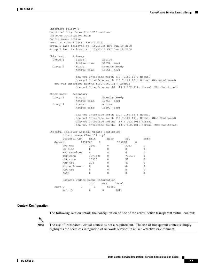
OL-17051-01 Active/Active Service Chassis Design
Interface Policy 2Monitored Interfaces 2 of 250 maximumfailover replication httpConfig sync: activeVersion: Ours 3.2(4), Mate 3.2(4)Group 1 last failover at: 10:19:34 EST Jun 19 2008Group 2 last failover at: 13:32:10 EST Jun 19 2008
This host: Primary Group 1 State: Active Active time: 36694 (sec) Group 2 State: Standby Ready Active time: 11551 (sec)
dca-vc1 Interface north (10.7.162.10): Normal dca-vc1 Interface south (10.7.162.10): Normal (Not-Monitored) dca-vc2 Interface north2 (10.7.152.11): Normal dca-vc2 Interface south2 (10.7.152.11): Normal (Not-Monitored)
Other host: Secondary Group 1 State: Standby Ready Active time: 10763 (sec) Group 2 State: Active Active time: 35890 (sec)
dca-vc1 Interface north (10.7.162.11): Normal dca-vc1 Interface south (10.7.162.11): Normal (Not-Monitored) dca-vc2 Interface north2 (10.7.152.10): Normal dca-vc2 Interface south2 (10.7.152.10): Normal (Not-Monitored)
Stateful Failover Logical Update Statistics Link : state Vlan 171 (up) Stateful Obj xmit xerr rcv rerr General 1094268 0 736028 0 sys cmd 3263 0 3263 0 up time 0 0 0 0 RPC services 0 0 0 0 TCP conn 1077406 0 732670 0 UDP conn 13395 0 52 0 ARP tbl 204 0 43 0 Xlate_Timeout 0 0 0 0 AAA tbl 0 0 0 0 DACL 0 0 0 0
Logical Update Queue Information Cur Max Total Recv Q: 0 1 53682 Xmit Q: 0 0 3641
Context Configuration
The following section details the configuration of one of the active-active transparent virtual contexts.
Note The use of transparent virtual context is not a requirement. The use of transparent contexts simply highlights the seamless integration of network services in an active/active environment.
77Data Center Service Integration: Service Chassis Design Guide
OL-17051-01

OL-17051-01 Active/Active Service Chassis Design
The FWSM system context defines the virtual contexts and associates specific VLAN interfaces with those contexts. The network administrator may choose to use these interfaces in routed or bridged mode. It is dependent on the firewall mode. To configure the virtual context as transparent use the following command within the virtual context:
firewall transparent
The show firewall command verifies the proper mode is enabled.
show firewall Firewall mode: Transparent
The network administrator uses the context’s VLAN interfaces to create a firewall bridge. Each interface associates itself with a bridge-group, two interfaces in the same bridge group comprise a Bridged Virtual Interface or BVI. The BVI is assigned an IP address that is accessible by both the “north” and “south” VLANs of the firewall. These two distinct VLANs become “stitched” together by the virtual context.
In the example below, VLANs 161 and 162 are members of bridge group 10. The BVI 10 interface further defines this coupling by defining an IP address that is accessible on both VLAN 161 and 162. The secure zone is “south” of the 162 VLAN interface. Layer 2 forwarding ensures that the firewall security policies are applied to all inbound and outbound traffic.
interface Vlan161 nameif north bridge-group 10 security-level 0!interface Vlan162 nameif south bridge-group 10 security-level 100!interface BVI10 ip address 10.7.162.10 255.255.255.0 standby 10.7.162.11
In this design, monitoring the "north" VLAN interface allows the FWSM and its associated contexts to take advantage of the autostate messages sent from the Catalyst supervisor engine. In a transparent deployment, where two VLANs are bridged via the FWSM virtual context, monitoring a single interface is sufficient. The service chassis aggregation links support both the north and south interface VLANs on the FWSM virtual context. Monitoring either of the two allows one to recognize a failure condition and expedite the failover process. The following is an example of the interface monitoring configuration:
monitor-interface north
Note The show failover command example output above indicates the interfaces being monitored for each virtual context.
Note The use of autostate and interface monitoring is optional if data and fault tolerant VLANs share the same physical interfaces. See the “Physical Connectivity” section on page 29 for more details.
The firewall implicitly denies all traffic on its interfaces, therefore the network administrator must define what traffic types are permissible. One such Ethernet traffic type that must be allowed are BPDUs. As discussed earlier in this document, the Services Chassis layer is a layer 2 domain contained by layer 3 devices located in the Aggregation layer of the data center. It is strongly recommended to enable RPVST+ to account for the redundant traffic paths this design introduces. In this design, the firewall is
78Data Center Service Integration: Service Chassis Design Guide
OL-17051-01

OL-17051-01 Active/Active Service Chassis Design
part of the loop, positioned as “bump on the wire”, which requires spanning tree’s services. The FWSM is able to process these BPDUs, modifying the trunked VLAN information in the frame between the ingress and egress interfaces.
To allow BPDUs across the FWSM transparent virtual context, the network administrator must define an access-list such as the one below. This access list must then be applied to each of the interfaces in the bridge group.
access-list BPDU ethertype permit bpdu!access-group BPDU in interface northaccess-group BPDU in interface south
In addition to BPDUs, the transparent virtual context must allow neighbor adjacencies to form between the routing devices located at the Aggregation layer. This requires extended access lists to permit these special traffic types. Table 2 highlights the protocols that require additional configuration on the FWSM.
The following is an example access list to permit EIGRP across the transparent virtual firewall.
access-list EIGRP extended permit 88 any any
Note The network administrator must define all acceptable application traffic and apply these access lists to the interfaces.
Multicast
The transparent firewall context supports multicast traffic to the extent that it allows it through the firewall. To do so it is necessary to create an extended access list to permit the flows, see Table 2 above. In the Active-Active design model, the Aggregation layer PIM routers create peer relationships through the FWSM. The firewall context does not actively participate in the PIM relationships but it simply forwards for the multicast related messaging and streams.
Table 2 Transparent Firewall Special Traffic Types
Traffic Type Protocol or Port Notes
DHCP UDP ports 67 and 68 If you enable the DHCP server, then the FWSM does not pass DHCP packets.
EIGRP Protocol 88 —
OSPF Protocol 89 —
Multicast streams
The UDP ports vary depending on the application
Multicast streams are always destined to a Class D address (224.0.0.0 to 239.x.x.x).
PIM Protocol 103
RIP (v1 or v2) UDP port 520 —
79Data Center Service Integration: Service Chassis Design Guide
OL-17051-01
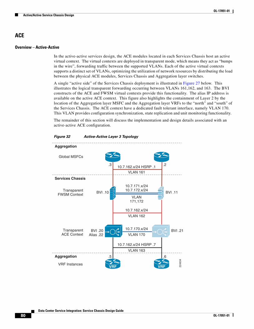
OL-17051-01 Active/Active Service Chassis Design
ACE
Overview – Active-Active
In the active-active services design, the ACE modules located in each Services Chassis host an active virtual context. The virtual contexts are deployed in transparent mode, which means they act as “bumps in the wire”, forwarding traffic between the supported VLANs. Each of the active virtual contexts supports a distinct set of VLANs, optimizing the utilization of network resources by distributing the load between the physical ACE modules, Services Chassis and Aggregation layer switches.
A single “active side” of the Services Chassis deployment is illustrated in Figure 27 below. This illustrates the logical transparent forwarding occurring between VLANs 161,162, and 163. The BVI constructs of the ACE and FWSM virtual contexts provide this functionality. The alias IP address is available on the active ACE context. This figure also highlights the containment of Layer 2 by the location of the Aggregation layer MSFC and the Aggregation layer VRFs to the “north” and “south” of the Services Chassis. The ACE context have a dedicated fault tolerant interface, namely VLAN 170. This VLAN provides configuration synchronization, state replication and unit monitoring functionality.
The remainder of this section will discuss the implementation and design details associated with an active-active ACE configuration.
Figure 32 Active-Active Layer 3 Topology
Services Chassis
Aggregation
Aggregation
VLAN 16110.7.162.x/24 HSRP .1
Global MSFCs
TransparentACE Context
TransparentFWSM Context
VRF Instances
VLAN 163
10.7.162.x/24 HSRP .7
.5 .6
.3
BVI .11
BVI .21
BVI .10
BVI .20Alias .22
.2
VLAN171,172
10.7.171.x/2410.7.172.x/24
VLAN 162
VLAN 170
10.7.170.x/24
10.7.162.x/24
2246
34
VRF VRF
80Data Center Service Integration: Service Chassis Design Guide
OL-17051-01

OL-17051-01 Active/Active Service Chassis Design
Catalyst 6500 IOS Implementation
The ACE service module resides within the Catalyst 6500 Services Chassis. In order to allow traffic to flow through the ACE module it is necessary to assign VLANs to the module. The example below highlights the Services Chassis configuration to support the ACE module. In addition, autostate messaging is enabled for fast convergence.
svclc autostatesvclc multiple-vlan-interfacessvclc module 5 vlan-group 1,2,152,153,162,163,999,svclc vlan-group 1 146svclc vlan-group 2 170svclc vlan-group 153 153svclc vlan-group 163 163svclc vlan-group 999 999
Note The details of the Catalyst 6500 configuration are available in the “Catalyst 6500 IOS Implementation” “Active/Standby Service Chassis Design” section on page 11.
Note The use of autostate and interface monitoring is optional if data and fault tolerant VLANs share the same physical interfaces. See the“Physical Connectivity” section on page 29.
Fault Tolerance Configuration
Each Services Chassis houses an ACE module, this physical redundancy is enhanced further through the use of fault tolerant groups between modules defined under the Admin context. Fault tolerant groups allow the network administrator to achieve a higher level of availability and load distribution in the data center by allowing the distribution of active virtual contexts between two peering ACE modules. This active-active design requires the network administrator to define at least two fault tolerant groups. To distribute the workload between the ACE modules and Services Chassis, set the primary and secondary priority for each fault tolerant group on alternating peers.
The following sample configuration details the active-active fault tolerant group settings. Notice that each fault tolerant group supports a different context. The higher “priority” setting determines the active peer in the ACE pairing. For example, the ACE module below is active for fault tolerant group “2” but is in HOT-STANDBY mode for fault tolerant group “3”. This means that each virtual context referenced under each fault tolerant group will inherit this high availability posture. All fault tolerant messaging including configuration synchronization, replicated traffic and ACE peering messages occur across the fault tolerant interface, in this case VLAN 170.
ft interface vlan 170 ip address 10.7.170.1 255.255.255.0 peer ip address 10.7.170.2 255.255.255.0 no shutdown
ft peer 1 heartbeat interval 100 heartbeat count 10 ft-interface vlan 170 query-interface vlan 999
ft group 1 peer 1 priority 150 peer priority 50 associate-context Admin
81Data Center Service Integration: Service Chassis Design Guide
OL-17051-01
OL-17051-01 Active/Active Service Chassis Design
inservice
ft group 2 peer 1 priority 150 peer priority 50 associate-context dca-ace-one inserviceft group 3 peer 1 priority 50 peer priority 150 associate-context dca-ace-two inservice
Note NoteThe fault tolerant parameters referenced above are fully explained under “Fault Tolerant Implementation” section on page 39.
The Admin ACE context defines the virtual contexts on the module. The network administrator names the context container and associates VLAN interfaces made accessible via the Catalyst 6500. In the example below, dca-ace-one and dca-ace-two are defined with two VLAN interfaces. These interfaces will be leveraged to provide transparent services.
context dca-ace-one description ** ACE Transparent Mode - ** allocate-interface vlan 162-163context dca-ace-two description ** 2nd ACE Transp. context ** allocate-interface vlan 152-153
Context Configuration
The transparent deployment model creates a Layer 2 forwarding path across the virtual ACE context to communicate with all servers “south” of the context. The virtual context is inline and must be able to support the various application needs and high availability requirements of the data center. This section of the document focuses on the ACE virtual context elements that address these goals including:
• Interface configuration
• Route Health Injection
• Object Tracking
• Multicast support
Note This document does not describe the ACE configuration basics. For more information on the ACE go to http://www.cisco.com/en/US/docs/interfaces_modules/services_modules/ace/v3.00_A2/configuration/quick/guide/getstart.html
Interface Configuration
The transparent ACE context leverages two VLAN interfaces, a “northern” interface facing the “southern” FWSM virtual context and a “southern” interface adjacent to a VRF located in the Aggregation layer. A transparent virtual context bridges these two VLANs, stitching them into a single
82Data Center Service Integration: Service Chassis Design Guide
OL-17051-01

OL-17051-01 Active/Active Service Chassis Design
layer 2 domain. To accomplish this task it is necessary to define a Bridged Virtual Interface (BVI). Defining a bridge group on each VLAN interface and assigning relevant layer 3 parameters for the local context and its remote peer construct the BVI.
As shown below, VLANs 162 and 163 comprise the bridge group. The 161 BVI has a local and remote peer address as well as the shared “alias” IP address that operates only on the active virtual context.
interface vlan 162 description ** North Side facing FWSM ** bridge-group 161no shutdowninterface vlan 163 description ** South Side facing Servers ** bridge-group 161no shutdown
interface bvi 161 ip address 10.7.162.20 255.255.255.0 alias 10.7.162.22 255.255.255.0 peer ip address 10.7.162.21 255.255.255.0 no shutdown
The ACE has an implicit deny on all interfaces, therefore it is necessary to define the permissible traffic types for each interface. This typically is limited to application traffic such as HTTP, HTTPs, and FTP. However the deployment of a transparent virtual context in this design introduces layer 2 loops in the data center. As discussed earlier, spanning tree is recommended to contend with the loops introduced in this design. For that reason, BPDUs must be allowed to traverse the device. The following Ethernet type access list must be enabled on both the “north” and “south” interfaces.
access-list BPDU ethertype permit bpdu
Route Health Injection (RHI)
RHI advertises the availability of a VIP across the network. The ACE supports RHI when there is a local routing instance configured on the MSFC, without a local routing presence the ACE cannot inject a route. In the active-active design, the Services Chassis's do not have a routing instance, however, this does not preclude the use of RHI with this design.
In testing, one of the active transparent virtual ACE contexts defines a VIP, 10.7.162.100, as shown below. The ACE does not advertise this host route.
class-map match-all VIP_180 description *VIP for VLAN 180* 2 match virtual-address 10.7.162.100 any
To monitor the state of the VIP and reflect this status in the routing table, the network administrator should employ IP SLA-based RHI. In the following example, IP SLA is enabled on the Aggregation layer switches. The IP SLA “monitor” configuration defines the type of SLA probe to assess VIP state, in this case TCP. In addition, the interval and dead-timer for this monitor are set. The IP SLA monitor is made operation by the schedule command that runs to infinity.
ip sla monitor 1 type tcpConnect dest-ipaddr 10.7.162.100 dest-port 80 source-ipaddr 10.7.162.3 control disable timeout 3000 frequency 5ip sla monitor schedule 1 life forever start-time now
83Data Center Service Integration: Service Chassis Design Guide
OL-17051-01

OL-17051-01 Active/Active Service Chassis Design
Since this is an active-active design, a similar probe determines the state of another VIP (10.7.152.100) housed on another Services Chassis.
ip sla monitor 2 type tcpConnect dest-ipaddr 10.7.152.100 dest-port 80 source-ipaddr 10.7.152.3 control disable timeout 3000 frequency 5ip sla monitor schedule 2 life forever start-time now
The track object monitors the status or returned value from the IP SLA probe. For each SLA the network administrator will have an associated tracked object configured. Below, the tracked objects “1” and “2” are associated with the similarly named SLAs.
track 1 rtr 1 delay down 5 up 5!track 2 rtr 2 delay down 5 up 5
Note The “down” and “up” delay defined in the tracked object will prevent route flapping.
The tracked object is then associated with a static route for the VIP with next hop being the alias IP address of the ACE virtual context. By adjusting the metric of the static route the preferred path through the Aggregation layer is set. In this case, there is a higher cost associated with the 10.7.152.100 route on this aggregation switch, the other aggregation switch the route cost would favor 10.7.152.100 and penalize the 10.7.162.100 VIP. In this manner the active-active design can distribute incoming VIP load between the core and Aggregation layers.
ip route 10.7.162.100 255.255.255.255 10.7.162.22 track 1ip route 10.7.152.100 255.255.255.255 10.7.152.22 50 track 2
The show track command confirms that the VIPs are available. While the “show ip route” command confirms the metrics are properly implemented. It is important to redistribute these static routes into the Core to achieve the desired results.
show track Track 1 Response Time Reporter 1 state State is Up 10 changes, last change 00:02:49 Delay up 5 secs, down 5 secs Latest operation return code: OK Latest RTT (millisecs) 4 Tracked by: STATIC-IP-ROUTINGTrack-list 0Track 2 Response Time Reporter 2 state State is Up 10 changes, last change 00:02:49 Delay up 5 secs, down 5 secs Latest operation return code: OK Latest RTT (millisecs) 4 Tracked by: STATIC-IP-ROUTINGTrack-list 0
show ip routeS 10.7.162.100/32 [1/0] via 10.7.162.22
84Data Center Service Integration: Service Chassis Design Guide
OL-17051-01

OL-17051-01 Conclusion
S 10.7.152.100/32 [50/0] via 10.7.152.22
Object Tracking
Object tracking allows the ACE virtual context to determine its status based on the status of objects external to the ACE. The active-active Services Chassis design tracked the bridge group VLAN interfaces. In the example below, VLAN 162 is the “northern” interface, which exists between the transparent ACE virtual context and the transparent FWSM virtual context. VLAN 163 is the server facing or “southern” interface on the ACE context. As shown by the priority setting, the failure of either VLAN on the Services Chassis would result in this ACE context failing over to its peer device.
ft track interface TrackVlan162 track-interface vlan 162 peer track-interface vlan 162 priority 150 peer priority 50ft track interface TrackVlan163 track-interface vlan 163 peer track-interface vlan 163 priority 150 peer priority 50
Note Interface tracking permits the ACE context to act on autostate messages received from the Services Chassis supervisor engine.
Multicast
The ACE transparent virtual context supports multicast traffic. In this deployment model packets received are forwarded to the other interface in the bridge group. To enable multicast across the transparent ACE it is necessary to configure an extended ACL to permit the protocol type. In this manner, the ACE does not actively participate with multicast at Layer 3.
access-list MCAST line 16 extended permit pim any any
Note CSCsm52480 - All IPv6 multicast packets are dropped by the ACE even though the module is properly configured. This behavior is observed only with IPv6 multicast packets and does not occur with IPv6 unicast packets. Workaround: None. http://www.cisco.com/en/US/docs/interfaces_modules/services_modules/ace/v3.00_A2/release/note/RACEA2X.html#wp370577
ConclusionThis Cisco Validated Services Chassis design provides two sample logical models built off of a common dual-homed physical architecture. The Active-Standby model provides a simple, one-sided traffic flow that is optimized for ease of implementation and troubleshooting. The Active-Active model provides a more advanced example of leveraging the virtualization capabilities of Cisco data center products, and allows the network designer to distribute traffic across both sides of a redundant physical architecture. Both of these models were validated from a primarily client/server perspective, with a traffic profile representative of HTTP-based frontend applications.
85Data Center Service Integration: Service Chassis Design Guide
OL-17051-01

OL-17051-01 Cisco Validated Design
Implementation models for services in the data center may be significantly affected by specific applications in use, traffic volume, access requirements, existing network architectures and other customer-specific constraints. The Cisco Validated Design models discussed in this document provide a starting point upon which customer-specific network designs may be based. The included discussion of the pros and cons of some of the relevant design alternatives also provides context for how these designs may be extended and adapted into live customer network environments.
Cisco Validated DesignThe Cisco Validated Design Program consists of systems and solutions designed, tested, and documented to facilitate faster, more reliable, and more predictable customer deployments. For more information visit http://www.cisco.com/en/US/netsol/ns741/networking_solutions_program_home.html.
ALL DESIGNS, SPECIFICATIONS, STATEMENTS, INFORMATION, AND RECOMMENDATIONS (COLLECTIVELY, "DESIGNS") IN THIS MANUAL ARE PRESENTED "AS IS," WITH ALL FAULTS. CISCO AND ITS SUPPLIERS DISCLAIM ALL WARRANTIES, INCLUDING, WITHOUT LIMITATION, THE WARRANTY OF MERCHANTABILITY, FITNESS FOR A PARTICULAR PURPOSE AND NONINFRINGEMENT OR ARISING FROM A COURSE OF DEALING, USAGE, OR TRADE PRACTICE. IN NO EVENT SHALL CISCO OR ITS SUPPLIERS BE LIABLE FOR ANY INDIRECT, SPECIAL, CONSEQUENTIAL, OR INCIDENTAL DAMAGES, INCLUDING, WITHOUT LIMITATION, LOST PROFITS OR LOSS OR DAMAGE TO DATA ARISING OUT OF THE USE OR INABILITY TO USE THE DESIGNS, EVEN IF CISCO OR ITS SUPPLIERS HAVE BEEN ADVISED OF THE POSSIBILITY OF SUCH DAMAGES.
THE DESIGNS ARE SUBJECT TO CHANGE WITHOUT NOTICE. USERS ARE SOLELY RESPONSIBLE FOR THEIR APPLICATION OF THE DESIGNS. THE DESIGNS DO NOT CONSTITUTE THE TECHNICAL OR OTHER PROFESSIONAL ADVICE OF CISCO, ITS SUPPLIERS OR PARTNERS. USERS SHOULD CONSULT THEIR OWN TECHNICAL ADVISORS BEFORE IMPLEMENTING THE DESIGNS. RESULTS MAY VARY DEPENDING ON FACTORS NOT TESTED BY CISCO.
CCDE, CCENT, Cisco Eos, Cisco Lumin, Cisco Nexus, Cisco StadiumVision, Cisco TelePresence, the Cisco logo, DCE, and Welcome to theHuman Network are trademarks; Changing the Way We Work, Live, Play, and Learn and Cisco Store are service marks; and Access Registrar,Aironet, AsyncOS, Bringing the Meeting To You, Catalyst, CCDA, CCDP, CCIE, CCIP, CCNA, CCNP, CCSP, CCVP, Cisco, the Cisco CertifiedInternetwork Expert logo, Cisco IOS, Cisco Press, Cisco Systems, Cisco Systems Capital, the Cisco Systems logo, Cisco Unity, CollaborationWithout Limitation, EtherFast, EtherSwitch, Event Center, Fast Step, Follow Me Browsing, FormShare, GigaDrive, HomeLink, Internet Quotient,IOS, iPhone, iQ Expertise, the iQ logo, iQ Net Readiness Scorecard, iQuick Study, IronPort, the IronPort logo, LightStream, Linksys, MediaTone,MeetingPlace, MeetingPlace Chime Sound, MGX, Networkers, Networking Academy, Network Registrar, PCNow, PIX, PowerPanels, ProConnect,ScriptShare, SenderBase, SMARTnet, Spectrum Expert, StackWise, The Fastest Way to Increase Your Internet Quotient, TransPath, WebEx, andthe WebEx logo are registered trademarks of Cisco Systems, Inc. and/or its affiliates in the United States and certain other countries.
All other trademarks mentioned in this document or Website are the property of their respective owners. The use of the word partner does not implya partnership relationship between Cisco and any other company. (0807R)
86Data Center Service Integration: Service Chassis Design Guide
OL-17051-01