Embed Size (px)
Citation preview
Data-Driven Synthesis for Object-Oriented Frameworks
Kuat Yessenov Zhilei Xu Armando Solar-Lezama ∗
Massachusetts Institute of Technology{kuat,timxu,asolar}@csail.mit.edu
AbstractSoftware construction today often involves the useof large frameworks. The challenge in this type ofprogramming is that object-oriented frameworks tendto grow exceedingly intricate; they spread functionalityamong numerous classes, and any use of the frameworkrequires knowledge of many interacting components.We present a system named MatchMaker that froma simple query synthesizes code that interacts with theframework. The query consists of names of two frame-work classes, and our system produces code enablinginteraction between them. MatchMaker relies on adatabase of dynamic program traces called DeLightthat uses novel abstraction-based indexing techniques toanswer queries about the evolution of heap connectivityin a matter of seconds.The paper evaluates the performance and effectivenessof MatchMaker on a number of benchmarks from theEclipse framework. The paper also presents the resultsof a user study that showed a 49% average productivityimprovement from the use of our tool.
Categories and Subject Descriptors D.2.2 [DesignTools and Techniques]: Computer-aided software engi-neering; I.2.2 [Automatic Programming]: Program syn-thesis
General Terms Human Factors
Keywords Program Synthesis, Dynamic Instrumenta-tion, Thin Slicing, Software Engineering
1. IntroductionModern programming relies heavily on extensible frame-works that pack large amounts of functionality. These∗ All authors are primary authors, listed in reverse alphabetical order.
Permission to make digital or hard copies of all or part of this work forpersonal or classroom use is granted without fee provided that copiesare not made or distributed for profit or commercial advantage andthat copies bear this notice and the full citation on the first page. Tocopy otherwise, to republish, to post on servers or to redistribute tolists, requires prior specific permission and/or a fee.OOPSLA’11, October 22–27, 2011, Portland, Oregon, USA.Copyright c© 2011 ACM 978-1-4503-0940-0/11/10. . . $10.00
frameworks make it possible to write rich applicationsby piecing together pre-existing components, but theproductivity benefits come at a price: a significant learn-ing curve as programmers master a complex frameworkwith thousands of components. Synthesis [14, 16, 18] canalleviate this problem by leveraging the novice program-mer’s limited understanding of the system to generatecode that uses the framework. Specifically, this paperdemonstrates the potential impact of synthesis through anew tool, MatchMaker, that addresses a concrete pro-gramming challenge: establishing an interaction betweentwo framework classes.
The problem arises from the way object-oriented frame-works factor functionality into a multitude of compo-nents. This factoring makes the framework flexible, butit also implies that interactions that look simple at ahigh level require collaboration of a number of auxil-iary objects. As a consequence, the user must write gluecode whose sole purpose is to coordinate these auxiliaryobjects.
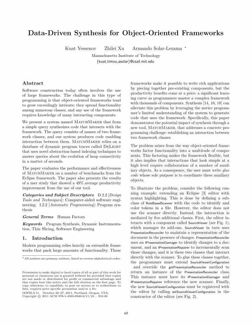
To illustrate the problem, consider the following run-ning example: extending an Eclipse [3] editor withsyntax highlighting. This is done by defining a sub-class of RuleBasedScanner with the code to identify andcolor tokens in a file. However, the editor does notuse the scanner directly. Instead, the interaction ismediated by five additional classes. First, the editor in-teracts with a component called SourceViewer (see Fig. 1),which manages its add-ons. SourceViewer in turn usesPresentationReconciler to maintain a representation of thedocument in the presence of changes. PresentationReconcileruses an IPresentationDamager to identify changes to a doc-ument, and an IPresentationRepairer to incrementally scanthose changes, and it is these two classes that interactdirectly with the scanner. To glue these classes together,the programmer must extend SourceViewerConfigurationand override the getPresentationReconciler method to
return an instance of the PresentationReconciler class.This instance must have its IPresentationDamager andIPresentationRepairer reference the new scanner. Finally,the new SourceViewerConfiguration must be registered withthe editor by calling setSourceViewerConfiguration in theconstructor of the editor (see Fig. 2).
65
class AbstractTextEditor {SourceViewerConfiguration fConfiguration;ISourceViewer fSourceViewer;createPartControl() {fSourceViewer = createSourceViewer();fSourceViewer.configure(fConfiguration);
}setSourceViewerConfiguration(config) {fConfiguration = config;
}}
class SourceViewer {IPresentationReconciler fPresentationReconciler;configure(SourceViewerConfiguration config) {fPresentationReconciler = config.getPresentationReconciler();
}}
Figure 1. Eclipse code in AbstractTextEditor (2950 LOC)and SourceViewer (537 LOC) relevant to interaction witha scanner.
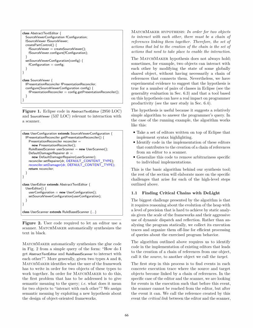
class UserConfiguration extends SourceViewerConfiguration {IPresentationReconciler getPresentationReconciler() {PresentationReconciler reconciler =
new PresentationReconciler();RuleBasedScanner userScanner = new UserScanner();DefaultDamagerRepairer dr =
new DefaultDamagerRepairer(userScanner);reconciler.setRepairer(dr, DEFAULT_CONTENT_TYPE);reconciler.setDamager(dr, DEFAULT_CONTENT_TYPE);return reconciler;
}}
class UserEditor extends AbstractTextEditor {UserEditor() {userConfiguration = new UserConfiguration();setSourceViewerConfiguration(userConfiguration);
}}
class UserScanner extends RuleBasedScanner {...}
Figure 2. User code required to let an editor use ascanner. MatchMaker automatically synthesizes thetext in black.
MatchMaker automatically synthesizes the glue codein Fig. 2 from a simple query of the form: “How do Iget AbstractTextEditor and RuleBasedScanner to interact witheach other?”. More generally, given two types A and B,MatchMaker identifies what the user of the frameworkhas to write in order for two objects of these types towork together. In order for MatchMaker to do this,the first problem that has to be addressed is to givesemantic meaning to the query; i.e. what does it meanfor two objects to “interact with each other”? We assignsemantic meaning by exploiting a new hypothesis aboutthe design of object-oriented frameworks.
MatchMaker hypothesis: In order for two objectsto interact with each other, there must be a chain ofreferences linking them together. Therefore, the set ofactions that led to the creation of the chain is the set ofactions that need to take place to enable the interaction.The MatchMaker hypothesis does not always hold;sometimes, for example, two objects can interact witheach other by modifying the state of some globallyshared object, without having necessarily a chain ofreferences that connects them. Nevertheless, we haveexperimental evidence to suggest that the hypothesis istrue for a number of pairs of classes in Eclipse (see thegenerality evaluation in Sec. 6.3) and that a tool basedon this hypothesis can have a real impact on programmerproductivity (see the user study in Sec. 6.4).The hypothesis is useful because it suggests a relativelysimple algorithm to answer the programmer’s query. Inthe case of the running example, the algorithm workslike this:• Take a set of editors written on top of Eclipse thatimplement syntax highlighting.
• Identify code in the implementation of these editorsthat contributes to the creation of a chain of referencesfrom an editor to a scanner.
• Generalize this code to remove arbitrariness specificto individual implementations.
This is the basic algorithm behind our synthesis tool;the rest of the section will elaborate more on the specificchallenges that arise for each of the high-level stepsoutlined above.
1.1 Finding Critical Chains with DeLight
The biggest challenge presented by the algorithm is thatit requires reasoning about the evolution of the heap witha level of precision that is hard to achieve by static analy-sis given the scale of the frameworks and their aggressiveuse of dynamic dispatch and reflection. Rather than an-alyzing the program statically, we collect its executiontraces and organize them off-line for efficient processingof queries about the exercised program behavior.The algorithm outlined above requires us to identifycode in the implementation of existing editors that leadsto the creation of a chain of references from one object,call it the source, to another object we call the target.The first step in this process is to find events in eachconcrete execution trace where the source and targetobjects become linked by a chain of references. In thespecific case of the editor and the scanner, we are lookingfor events in the execution such that before this event,the scanner cannot be reached from the editor, but afterthe event it can. We call the reference created by thisevent the critical link between the editor and the scanner,
66
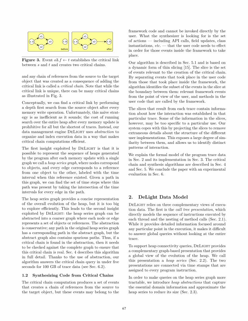
Figure 3. Event o3.f ← t establishes the critical linkbetween s and t and creates two critical chains.
and any chain of references from the source to the targetobject that was created as a consequence of adding thecritical link is called a critical chain. Note that while thecritical link is unique, there can be many critical chainsas illustrated in Fig. 3.Conceptually, we can find a critical link by performinga depth first search from the source object after everymemory write operation. Unfortunately, this naïve strat-egy is as inefficient as it sounds; the cost of runningsearch over the entire heap after every memory update isprohibitive for all but the shortest of traces. Instead, ourdata management engine DeLight uses abstraction toorganize and index execution data in a way that makescritical chain computations efficient.The first insight exploited by DeLight is that it ispossible to represent the sequence of heaps generatedby the program after each memory update with a singlegraph we call a heap series graph, where nodes correspondto objects, and every edge corresponds to a referencefrom one object to the other, labeled with the timeinterval when this reference existed. Given a path inthis graph, we can find the set of time steps where thispath was present by taking the intersection of the timeintervals for every edge in the path.The heap series graph provides a concise representationof the overall evolution of the heap, but it is too bigto explore efficiently. This leads to the second insightexploited by DeLight: the heap series graph can beabstracted into a coarser graph where each node or edgerepresents a set of objects or references. The abstractionis conservative; any path in the original heap series graphhas a corresponding path in the abstract graph, but theabstract graph also contains spurious paths. Thus, if acritical chain is found in the abstraction, then it needsto be checked against the complete graph to ensure thatthis critical chain is real. Sec. 4 describes this algorithmin full detail. Thanks to the use of abstraction, ouralgorithm answers the critical chain query in under fiveseconds for 100 GB of trace data (see Sec. 6.2).
1.2 Synthesizing Code from Critical Chains
The critical chain computation produces a set of eventsthat creates a chain of references from the source tothe target object, but these events may belong to the
framework code and cannot be invoked directly by theuser. What the synthesizer is looking for is the setof actions — including API calls, field updates, classinstantiations, etc. — that the user code needs to effectin order for those events inside the framework to takeplace.
Our algorithm is described in Sec. 5.1 and is based ona dynamic form of thin slicing [15]. The slice is the setof events relevant to the creation of the critical chain.By separating events that took place in the user codefrom those that took place inside the framework, thealgorithm identifies the subset of the events in the slice atthe boundary between them: relevant framework eventsfrom the point of view of the user, and methods in theuser code that are called by the framework.
The slices that result from each trace contain informa-tion about how the interaction was established in thatparticular trace. Some of the information in the slices,however, may be too specific to a particular use. Oursystem copes with this by projecting the slices to removeextraneous details about the structure of the differentuser implementations. This exposes a large degree of sim-ilarity between them, and allows us to identify distinctpatterns of interaction.
We explain the formal model of the program trace datain Sec. 2 and its implementation in Sec. 3. The criticalchain and synthesis algorithms are described in Sec. 4and Sec. 5. We conclude the paper with an experimentalevaluation in Sec. 6.
2. DeLight Data ModelDeLight relies on three complementary views of execu-tion data. The first is the call tree presentation, whichdirectly models the sequence of instructions executed byeach thread and the nesting of method calls (Sec. 2.1).While it provides detailed information focused aroundany particular point in the execution, it makes it difficultto answer global queries without looking at the entiretrace.
To support heap connectivity queries, DeLight providesa complementary graph-based presentation that providesa global view of the evolution of the heap. We callthis presentation a heap series (Sec. 2.2). The twopresentations are connected via time stamps that areassigned to every program instruction.
In order to make queries on the heap series graph moretractable, we introduce heap abstractions that capturethe essential domain information and approximate theheap series to reduce its size (Sec. 2.3).
67
2.1 Call Tree PresentationThis presentation is essentially a sequence of events.An event is triggered for every state update and everytransition across method boundaries:Type Descriptiona← b.f Read of value a from field f of object b.a← f Read from a static field f .a← b[i] Read of value a from array b.b.f ← a Write of value a into field f of object b.f ← a Write to a static field f .b[i]← a Write of value a into array b.call m(p) Method enter.return a Normal exit of a method.throw e Exceptional exit of a method.
The sequence p in method enter events is the sequenceof parameters to the method call, starting with this fornon-static methods. Values V in our model consist ofobject instances, the special value null, and primitivevalues (integer, void, etc.) type(a) denotes Java type ofvalue a. Each event is assigned a unique timestamp (oras we call it later, its time), which among other thingsallows us to assign a total order to events executed bydifferent threads. Conceptually, method enter and exitevents for a single thread form a call tree where the leafnodes are the state reads and writes. This presentationprovides a pre-order traversal of the call tree, allowingus to query information in the dynamic call scope of anygiven event as used, for example, in computing slices.
2.2 Heap Series PresentationThe call tree presentation is useful for analyzing callpatterns, but when reasoning about the evolution ofheap connectivity, a graph-based view is more desirable.A heap H in our model is a directed multi-graph on theset of values V and edges labeled by fields F . An edgea
f−→ b denotes the fact that the value of non-static fieldf of an object instance a is b. We use set algebra on theset of edges to describe updates to a multi-graph.The effect of an event on the heap is the addition andremoval of edges. Starting from the empty heap H0, webuild a sequence of heaps {Ht} by applying t-th eventto Ht−1. The rule for the field write event is:
[[b.f ← a]]H =(H \ (b f−→ V)
)∪ (b f−→ a)
(all f edges coming out from b are removed and an fedge from b to a is added.) We do not store static fieldwrites in the heap model, and the remaining events haveno heap side-effects.The sequence of heaps {Ht} is compacted into a heapseries presentation H, which is a directed multi-graphon the set of values V and edges labelled by pairs offields F and non-empty time intervals: F × 2Z. Here
an edge records all indexes t for which Ht has an edgelabelled by f between the nodes:
a(f,T )−−−→ b ∈ H
whenever there was an edge in one of the heaps:
T = {t | a f−→ b ∈ Ht} ∧ |T | > 0
The heap series model and the call tree model areconnected by the times of the events. This allows usto quickly jump from a time on some edge in H to thecall stack for the corresponding event and vice versa.Time intervals are represented either as decision treesor as unions of disjoint segments. The motivation forusing time intervals instead of multiple heaps and thereal gain in compacting heap series come from a simpleobservation: most fields are not updated frequently.
Abstract fields Containers are pervasive in Java code,and their simple interfaces encapsulate complex heaprepresentations. DeLight approximates the internal be-havior of container objects via abstract fields. For exam-ple, we model lists with the binary relation content ∈ F ,where a
content−−−−→ b if a is an instance of java.util.ArrayListand b is an element of the list a. Similarly, the abstractfield values ∈ F matches a map to its values: a
values−−−→ bif a is an instance of java.util.HashMap and b is a value forsome key in the map a. Finally, the abstract field arrayrelates an array object to its elements.Figure 4 describes how DeLight computes heap seriesH by observing only the method enter and exit eventsfor collection classes. For example, List.remove takes aposition as an input and returns the removed list elementat that position, allowing us to deduce the effect onthe heap without knowing the list content ahead oftime. Note that unlike concrete fields, abstract fieldsmay have multiple edges between two instances (e.g.if a list contains duplicates) or many outgoing edgesfrom an instance (since containers usually have manyelements.) Using only method events does not let usbuild an absolutely precise model; DeLight does not,for example, handle element position in a list, removalvia an iterator, or null value in a map.
2.3 Heap Abstractions
The heap series graph H is quite large: the numberof nodes and edges easily reaches millions. To supportefficient computation on H, DeLight provides severalheap abstractions aimed to further reduce the size of thegraph using semantic domain knowledge while preservingproperties of interest. We use heap abstractions to deriveapproximate answers to queries which we then refineby selectively querying H. The critical property is the
68
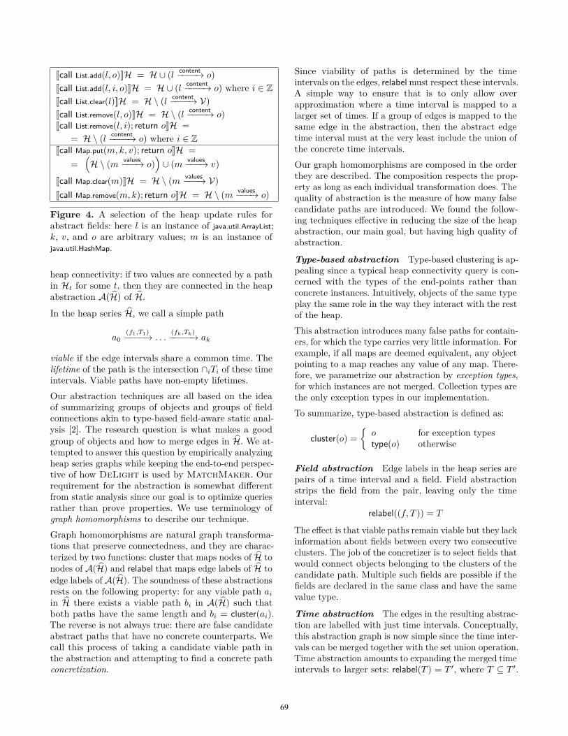
[[call List.add(l, o)]]H = H ∪ (l content−−−−→ o)[[call List.add(l, i, o)]]H = H ∪ (l content−−−−→ o) where i ∈ Z[[call List.clear(l)]]H = H \ (l content−−−−→ V)[[call List.remove(l, o)]]H = H \ (l content−−−−→ o)[[call List.remove(l, i); return o]]H =
= H \ (l content−−−−→ o) where i ∈ Z[[call Map.put(m, k, v); return o]]H =
=(H \ (m values−−−→ o)
)∪ (m values−−−→ v)
[[call Map.clear(m)]]H = H \ (m values−−−→ V)[[call Map.remove(m, k); return o]]H = H \ (m values−−−→ o)
Figure 4. A selection of the heap update rules forabstract fields: here l is an instance of java.util.ArrayList;k, v, and o are arbitrary values; m is an instance ofjava.util.HashMap.
heap connectivity: if two values are connected by a pathin Ht for some t, then they are connected in the heapabstraction A(H) of H.
In the heap series H, we call a simple path
a0(f1,T1)−−−−→ . . .
(fk,Tk)−−−−−→ ak
viable if the edge intervals share a common time. Thelifetime of the path is the intersection ∩iTi of these timeintervals. Viable paths have non-empty lifetimes.Our abstraction techniques are all based on the ideaof summarizing groups of objects and groups of fieldconnections akin to type-based field-aware static anal-ysis [2]. The research question is what makes a goodgroup of objects and how to merge edges in H. We at-tempted to answer this question by empirically analyzingheap series graphs while keeping the end-to-end perspec-tive of how DeLight is used by MatchMaker. Ourrequirement for the abstraction is somewhat differentfrom static analysis since our goal is to optimize queriesrather than prove properties. We use terminology ofgraph homomorphisms to describe our technique.Graph homomorphisms are natural graph transforma-tions that preserve connectedness, and they are charac-terized by two functions: cluster that maps nodes of H tonodes of A(H) and relabel that maps edge labels of H toedge labels of A(H). The soundness of these abstractionsrests on the following property: for any viable path ai
in H there exists a viable path bi in A(H) such thatboth paths have the same length and bi = cluster(ai).The reverse is not always true: there are false candidateabstract paths that have no concrete counterparts. Wecall this process of taking a candidate viable path inthe abstraction and attempting to find a concrete pathconcretization.
Since viability of paths is determined by the timeintervals on the edges, relabel must respect these intervals.A simple way to ensure that is to only allow overapproximation where a time interval is mapped to alarger set of times. If a group of edges is mapped to thesame edge in the abstraction, then the abstract edgetime interval must at the very least include the union ofthe concrete time intervals.Our graph homomorphisms are composed in the orderthey are described. The composition respects the prop-erty as long as each individual transformation does. Thequality of abstraction is the measure of how many falsecandidate paths are introduced. We found the follow-ing techniques effective in reducing the size of the heapabstraction, our main goal, but having high quality ofabstraction.
Type-based abstraction Type-based clustering is ap-pealing since a typical heap connectivity query is con-cerned with the types of the end-points rather thanconcrete instances. Intuitively, objects of the same typeplay the same role in the way they interact with the restof the heap.This abstraction introduces many false paths for contain-ers, for which the type carries very little information. Forexample, if all maps are deemed equivalent, any objectpointing to a map reaches any value of any map. There-fore, we parametrize our abstraction by exception types,for which instances are not merged. Collection types arethe only exception types in our implementation.To summarize, type-based abstraction is defined as:
cluster(o) ={
o for exception typestype(o) otherwise
Field abstraction Edge labels in the heap series arepairs of a time interval and a field. Field abstractionstrips the field from the pair, leaving only the timeinterval:
relabel((f, T )) = T
The effect is that viable paths remain viable but they lackinformation about fields between every two consecutiveclusters. The job of the concretizer is to select fields thatwould connect objects belonging to the clusters of thecandidate path. Multiple such fields are possible if thefields are declared in the same class and have the samevalue type.
Time abstraction The edges in the resulting abstrac-tion are labelled with just time intervals. Conceptually,this abstraction graph is now simple since the time inter-vals can be merged together with the set union operation.Time abstraction amounts to expanding the merged timeintervals to larger sets: relabel(T ) = T ′, where T ⊆ T ′.
69
47600
47700
47800
47900
48000
48100
48200
1 4 16 64 256 1024N =47600
47700
47800
47900
48000
48100
48200
1 4 16 64 256 1024N =
Original graph
Abstraction
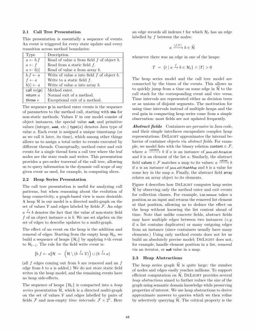
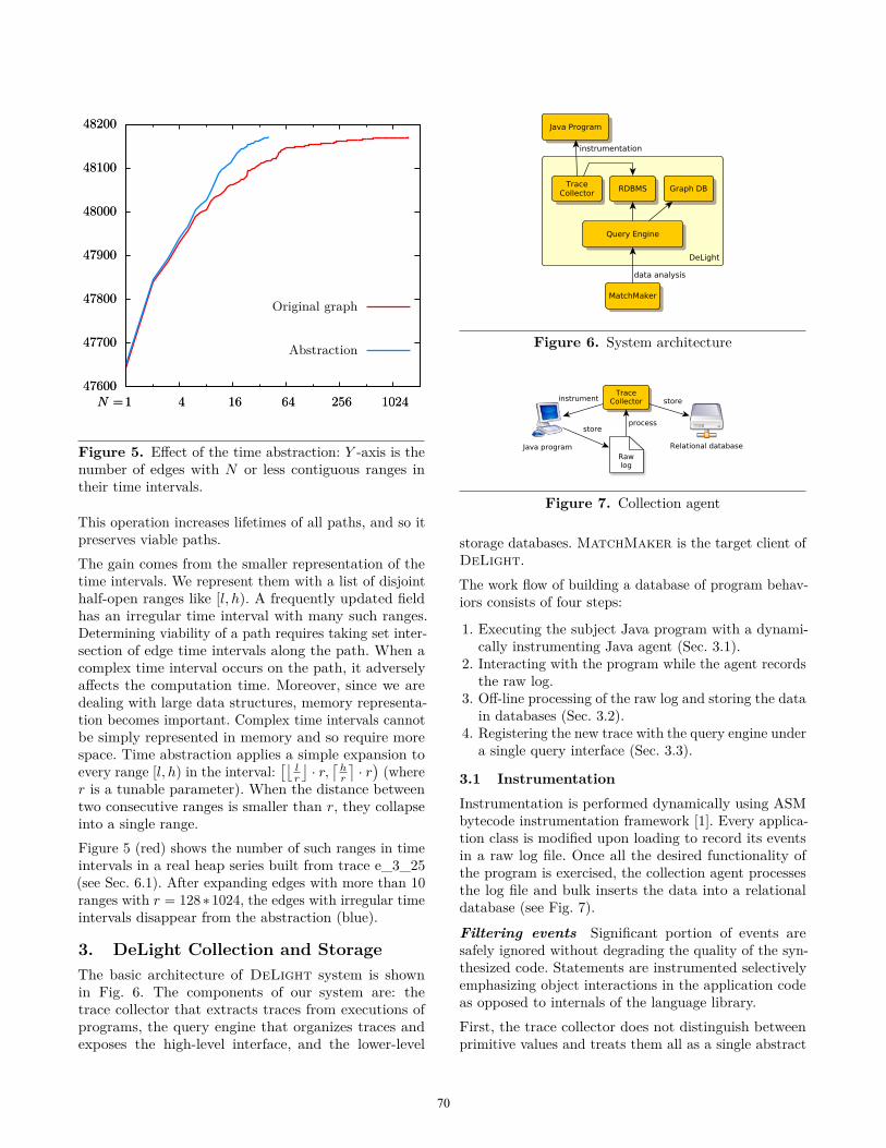
Figure 5. Effect of the time abstraction: Y -axis is thenumber of edges with N or less contiguous ranges intheir time intervals.
This operation increases lifetimes of all paths, and so itpreserves viable paths.The gain comes from the smaller representation of thetime intervals. We represent them with a list of disjointhalf-open ranges like [l, h). A frequently updated fieldhas an irregular time interval with many such ranges.Determining viability of a path requires taking set inter-section of edge time intervals along the path. When acomplex time interval occurs on the path, it adverselyaffects the computation time. Moreover, since we aredealing with large data structures, memory representa-tion becomes important. Complex time intervals cannotbe simply represented in memory and so require morespace. Time abstraction applies a simple expansion toevery range [l, h) in the interval:
[⌊lr
⌋· r,⌈
hr
⌉· r)(where
r is a tunable parameter). When the distance betweentwo consecutive ranges is smaller than r, they collapseinto a single range.Figure 5 (red) shows the number of such ranges in timeintervals in a real heap series built from trace e_3_25(see Sec. 6.1). After expanding edges with more than 10ranges with r = 128∗1024, the edges with irregular timeintervals disappear from the abstraction (blue).
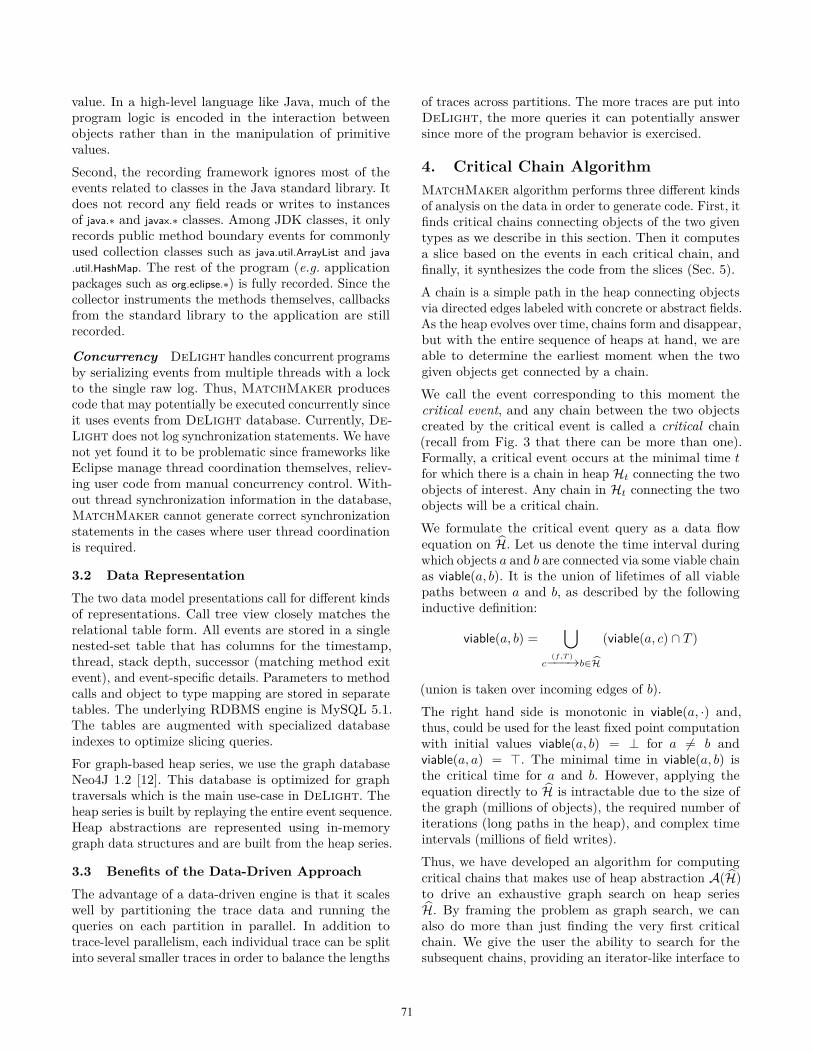
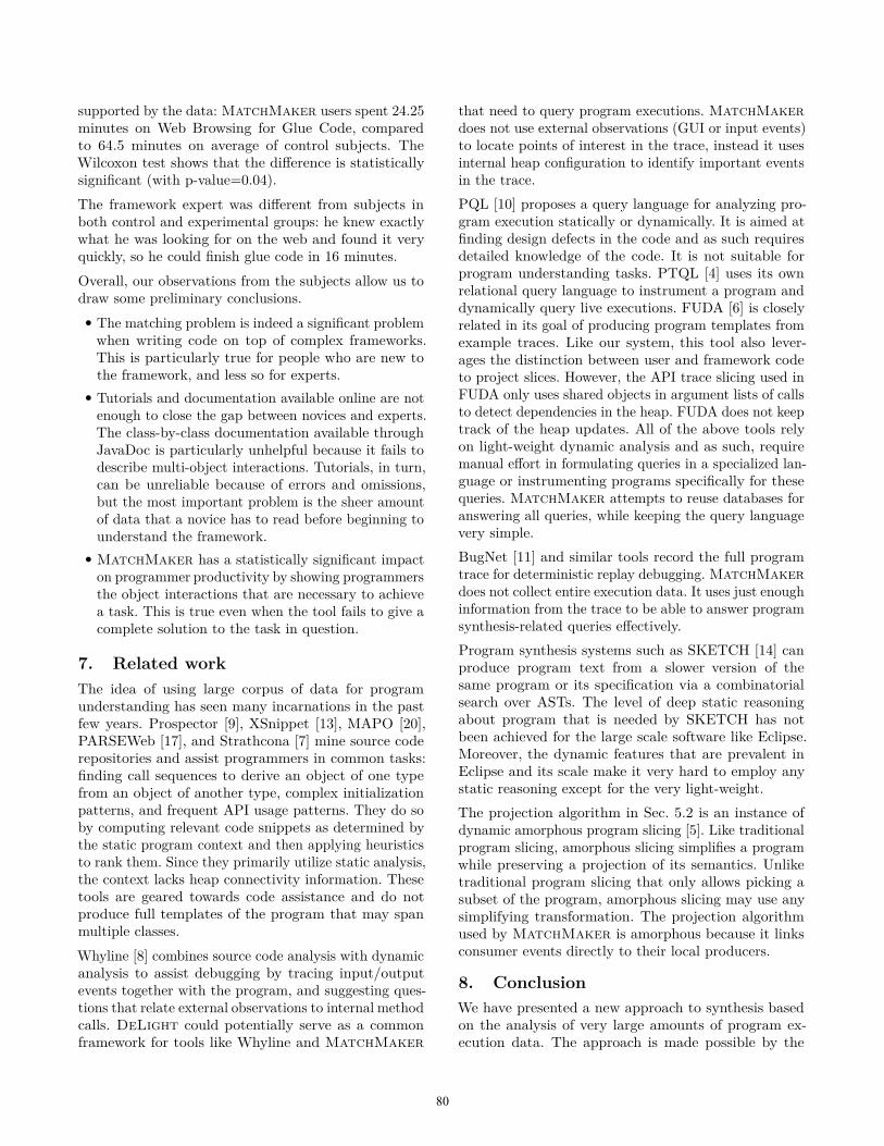
3. DeLight Collection and StorageThe basic architecture of DeLight system is shownin Fig. 6. The components of our system are: thetrace collector that extracts traces from executions ofprograms, the query engine that organizes traces andexposes the high-level interface, and the lower-level
Figure 6. System architecture
Figure 7. Collection agent
storage databases. MatchMaker is the target client ofDeLight.The work flow of building a database of program behav-iors consists of four steps:
1. Executing the subject Java program with a dynami-cally instrumenting Java agent (Sec. 3.1).
2. Interacting with the program while the agent recordsthe raw log.
3. Off-line processing of the raw log and storing the datain databases (Sec. 3.2).
4. Registering the new trace with the query engine undera single query interface (Sec. 3.3).
3.1 InstrumentationInstrumentation is performed dynamically using ASMbytecode instrumentation framework [1]. Every applica-tion class is modified upon loading to record its eventsin a raw log file. Once all the desired functionality ofthe program is exercised, the collection agent processesthe log file and bulk inserts the data into a relationaldatabase (see Fig. 7).
Filtering events Significant portion of events aresafely ignored without degrading the quality of the syn-thesized code. Statements are instrumented selectivelyemphasizing object interactions in the application codeas opposed to internals of the language library.First, the trace collector does not distinguish betweenprimitive values and treats them all as a single abstract
70
value. In a high-level language like Java, much of theprogram logic is encoded in the interaction betweenobjects rather than in the manipulation of primitivevalues.Second, the recording framework ignores most of theevents related to classes in the Java standard library. Itdoes not record any field reads or writes to instancesof java.∗ and javax.∗ classes. Among JDK classes, it onlyrecords public method boundary events for commonlyused collection classes such as java.util.ArrayList and java.util.HashMap. The rest of the program (e.g. applicationpackages such as org.eclipse.∗) is fully recorded. Since thecollector instruments the methods themselves, callbacksfrom the standard library to the application are stillrecorded.
Concurrency DeLight handles concurrent programsby serializing events from multiple threads with a lockto the single raw log. Thus, MatchMaker producescode that may potentially be executed concurrently sinceit uses events from DeLight database. Currently, De-Light does not log synchronization statements. We havenot yet found it to be problematic since frameworks likeEclipse manage thread coordination themselves, reliev-ing user code from manual concurrency control. With-out thread synchronization information in the database,MatchMaker cannot generate correct synchronizationstatements in the cases where user thread coordinationis required.
3.2 Data Representation
The two data model presentations call for different kindsof representations. Call tree view closely matches therelational table form. All events are stored in a singlenested-set table that has columns for the timestamp,thread, stack depth, successor (matching method exitevent), and event-specific details. Parameters to methodcalls and object to type mapping are stored in separatetables. The underlying RDBMS engine is MySQL 5.1.The tables are augmented with specialized databaseindexes to optimize slicing queries.For graph-based heap series, we use the graph databaseNeo4J 1.2 [12]. This database is optimized for graphtraversals which is the main use-case in DeLight. Theheap series is built by replaying the entire event sequence.Heap abstractions are represented using in-memorygraph data structures and are built from the heap series.
3.3 Benefits of the Data-Driven Approach
The advantage of a data-driven engine is that it scaleswell by partitioning the trace data and running thequeries on each partition in parallel. In addition totrace-level parallelism, each individual trace can be splitinto several smaller traces in order to balance the lengths
of traces across partitions. The more traces are put intoDeLight, the more queries it can potentially answersince more of the program behavior is exercised.
4. Critical Chain AlgorithmMatchMaker algorithm performs three different kindsof analysis on the data in order to generate code. First, itfinds critical chains connecting objects of the two giventypes as we describe in this section. Then it computesa slice based on the events in each critical chain, andfinally, it synthesizes the code from the slices (Sec. 5).A chain is a simple path in the heap connecting objectsvia directed edges labeled with concrete or abstract fields.As the heap evolves over time, chains form and disappear,but with the entire sequence of heaps at hand, we areable to determine the earliest moment when the twogiven objects get connected by a chain.We call the event corresponding to this moment thecritical event, and any chain between the two objectscreated by the critical event is called a critical chain(recall from Fig. 3 that there can be more than one).Formally, a critical event occurs at the minimal time tfor which there is a chain in heap Ht connecting the twoobjects of interest. Any chain in Ht connecting the twoobjects will be a critical chain.We formulate the critical event query as a data flowequation on H. Let us denote the time interval duringwhich objects a and b are connected via some viable chainas viable(a, b). It is the union of lifetimes of all viablepaths between a and b, as described by the followinginductive definition:
viable(a, b) =⋃
c(f,T )−−−→b∈H
(viable(a, c) ∩ T )
(union is taken over incoming edges of b).The right hand side is monotonic in viable(a, ·) and,thus, could be used for the least fixed point computationwith initial values viable(a, b) = ⊥ for a 6= b andviable(a, a) = >. The minimal time in viable(a, b) isthe critical time for a and b. However, applying theequation directly to H is intractable due to the size ofthe graph (millions of objects), the required number ofiterations (long paths in the heap), and complex timeintervals (millions of field writes).Thus, we have developed an algorithm for computingcritical chains that makes use of heap abstraction A(H)to drive an exhaustive graph search on heap seriesH. By framing the problem as graph search, we canalso do more than just finding the very first criticalchain. We give the user the ability to search for thesubsequent chains, providing an iterator-like interface to
71
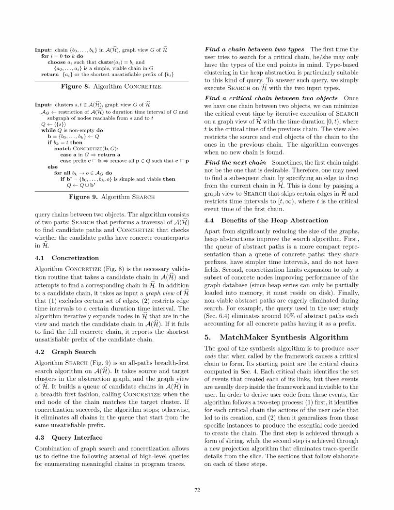
Input: chain {b0, . . . , bk} in A(H), graph view G of Hfor i = 0 to k do
choose ai such that cluster(ai) = bi and{a0, . . . , ai} is a simple, viable chain in G
return {ai} or the shortest unsatisfiable prefix of {bi}
Figure 8. Algorithm Concretize.
Input: clusters s, t ∈ A(H), graph view G of HAG ← restriction of A(H) to duration time interval of G and
subgraph of nodes reachable from s and to tQ← 〈{s}〉while Q is non-empty do
b = {b0, . . . , bk} ← Qif bk = t then
match Concretize(b, G):case a in G ⇒ return acase prefix c v b ⇒ remove all p ∈ Q such that c v p
elsefor all bk → o ∈ AG do
if b’ = {b0, . . . , bk, o} is simple and viable thenQ← Q ∪ b’
Figure 9. Algorithm Search
query chains between two objects. The algorithm consistsof two parts: Search that performs a traversal of A(H)to find candidate paths and Concretize that checkswhether the candidate paths have concrete counterpartsin H.
4.1 ConcretizationAlgorithm Concretize (Fig. 8) is the necessary valida-tion routine that takes a candidate chain in A(H) andattempts to find a corresponding chain in H. In additionto a candidate chain, it takes as input a graph view of Hthat (1) excludes certain set of edges, (2) restricts edgetime intervals to a certain duration time interval. Thealgorithm iteratively expands nodes in H that are in theview and match the candidate chain in A(H). If it failsto find the full concrete chain, it reports the shortestunsatisfiable prefix of the candidate chain.
4.2 Graph SearchAlgorithm Search (Fig. 9) is an all-paths breadth-firstsearch algorithm on A(H). It takes source and targetclusters in the abstraction graph, and the graph viewof H. It builds a queue of candidate chains in A(H) ina breadth-first fashion, calling Concretize when theend node of the chain matches the target cluster. Ifconcretization succeeds, the algorithm stops; otherwise,it eliminates all chains in the queue that start from thesame unsatisfiable prefix.
4.3 Query InterfaceCombination of graph search and concretization allowsus to define the following arsenal of high-level queriesfor enumerating meaningful chains in program traces.
Find a chain between two types The first time theuser tries to search for a critical chain, he/she may onlyhave the types of the end points in mind. Type-basedclustering in the heap abstraction is particularly suitableto this kind of query. To answer such query, we simplyexecute Search on H with the two input types.Find a critical chain between two objects Oncewe have one chain between two objects, we can minimizethe critical event time by iterative execution of Searchon a graph view of H with the time duration [0, t), wheret is the critical time of the previous chain. The view alsorestricts the source and end objects of the chain to theones in the previous chain. The algorithm convergeswhen no new chain is found.Find the next chain Sometimes, the first chain mightnot be the one that is desirable. Therefore, one may needto find a subsequent chain by specifying an edge to dropfrom the current chain in H. This is done by passing agraph view to Search that skips certain edges in H andrestricts time intervals to [t,∞), where t is the criticalevent time of the first chain.
4.4 Benefits of the Heap AbstractionApart from significantly reducing the size of the graphs,heap abstractions improve the search algorithm. First,the queue of abstract paths is a more compact repre-sentation than a queue of concrete paths: they shareprefixes, have simpler time intervals, and do not havefields. Second, concretization limits expansion to only asubset of concrete nodes improving performance of thegraph database (since heap series can only be partiallyloaded into memory, it must reside on disk). Finally,non-viable abstract paths are eagerly eliminated duringsearch. For example, the query used in the user study(Sec. 6.4) eliminates around 10% of abstract paths eachaccounting for all concrete paths having it as a prefix.
5. MatchMaker Synthesis AlgorithmThe goal of the synthesis algorithm is to produce usercode that when called by the framework causes a criticalchain to form. Its starting point are the critical chainscomputed in Sec. 4. Each critical chain identifies the setof events that created each of its links, but these eventsare usually deep inside the framework and invisible to theuser. In order to derive user code from these events, thealgorithm follows a two-step process: (1) first, it identifiesfor each critical chain the actions of the user code thatled to its creation, and (2) then it generalizes from thosespecific instances to produce the essential code neededto create the chain. The first step is achieved through aform of slicing, while the second step is achieved througha new projection algorithm that eliminates trace-specificdetails from the slice. The sections that follow elaborateon each of these steps.
72
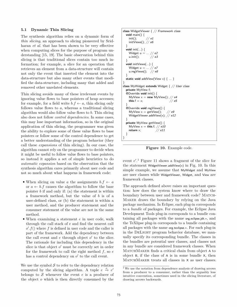
5.1 Dynamic Thin Slicing
The synthesis algorithm relies on a dynamic form ofthin slicing, an approach to slicing pioneered by Srid-haran et al. that has been shown to be very effectivewhen computing slices for the purpose of program un-derstanding [15, 19]. The basic observation behind thinslicing is that traditional slices contain too much in-formation; for example, a slice for an operation thatretrieves an element from a data-structure will containnot only the event that inserted the element into thedata-structure but also many other events that modi-fied the data-structure, including many that added andremoved other unrelated elements.Thin slicing avoids many of these irrelevant events byignoring value flows to base pointers of heap accesses;for example, for a field write b.f ← a, thin slicing onlyfollows value flows to a, whereas a traditional slicingalgorithm would also follow value flows to b. Thin slicingalso does not follow control dependencies. In some cases,this may lose important information, so in the originalapplication of thin slicing, the programmer was giventhe ability to explore some of these value flows to basepointers or follow some of the control dependence to geta better understanding of the program behavior (theycall these expansions of thin slicing). In our case, thealgorithm cannot rely on the programmer to decide whenit might be useful to follow value flows to base pointers,so instead it applies a set of simple heuristics to doautomatic expansion based on the observation that thesynthesis algorithm cares primarily about user code andnot so much about what happens in framework code:
• When slicing on value a the assignments b.f ← aor a ← b.f causes the algorithm to follow the basepointer b if and only if: (a) the statement is withina framework method, but the value of b is of auser-defined class, or (b) the statement is within auser method, and the producer statement and theconsumer statement of the value are not in the samemethod.
• When examining a statement e in user code, walkthrough the call stack of e and find the nearest callo′.f() where f is defined in user code and the caller ispart of the framework. Add the dependency betweenthe call event and e through object o′ to the slice.The rationale for including this dependency in theslice is that object o′ must be correctly set in orderfor the framework to call the right method f , so ehas a control dependency on o′ to the call event.
We use the symbol S to refer to the dependency relationcomputed by the slicing algorithm. A tuple e
o−→ e′
belongs to S whenever the event e is a producer ofthe object o which is then directly consumed by the
class WidgetViewer { // Framework classvoid main() {init(); // e1initViews(); // e6
}void init(...) {Widget u = ... // e2u.init(); // e3
}void initViews(...) {Widget u = ... // e7u.regViews(); // e8
}static void addView(View x) { ... }
}class MyWidget extends Widget { // User class
private MyView f;@Override void init() {MyView x = new MyView(); // e4this.f = x; // e5
}@Override void regViews() {MyView x = getView(); // e9WidgetViewer.addView(x); // e12
}private MyView getView() {MyView x = this.f; // e10return x; // e11
}}
Figure 10. Example code.
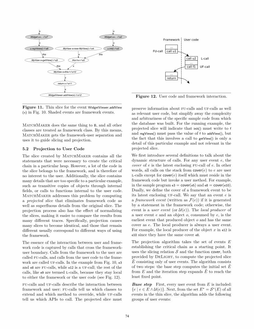
event e′.1 Figure 11 shows a fragment of the slice forthe statement WidgetViewer.addView(x) in Fig. 10. In thissimple example, we assume that MyWidget and MyVieware user classes while WidgetViewer, Widget, and View areframework classes.The approach defined above raises an important ques-tion: how does the system know where to draw theboundary between user and framework code? Match-Maker draws the boundary by relying on the Javapackage mechanism. In Eclipse, each plug-in correspondsto a bundle of packages. For example, the Eclipse JavaDevelopment Tools plug-in corresponds to a bundle con-taining all packages with the name org.eclipse.jdt.∗, andthe TeXlipse plug-in corresponds to a bundle containingall packages with the name org.texlipse.∗. For each plug-inin the DeLight program behavior database, we man-ually specify its corresponding bundle. The classes inthe bundles are potential user classes, and classes notin any bundle are considered framework classes. WhenMatchMaker finds a critical chain from object A toobject B, if the class of A is in some bundle X, thenMatchMaker treats all classes in X as user classes.
1 We use the notation from dependence analysis of drawing arrowsfrom a producer to a consumer, rather than the arguably lessintuitive convention, sometimes used in the slicing literature, ofdrawing arrows backwards.
73
Widget u=... // e2
u.init() // e3
u
this.f=x // e5
this
MyView x=new MyView() // e4
x
MyView x=this.f // e10
x
Widget u=... // e7
u.regViews() // e8
u
MyView x=getView() // e9
this
this
return x // e11
x
WidgetViewer.addView(x) // e12
x
u u
Figure 11. Thin slice for the event WidgetViewer.addView(x) in Fig. 10. Shaded events are framework events.
MatchMaker does the same thing to B, and all otherclasses are treated as framework class. By this means,MatchMaker gets the framework-user separation anduses it to guide slicing and projection.
5.2 Projection to User Code
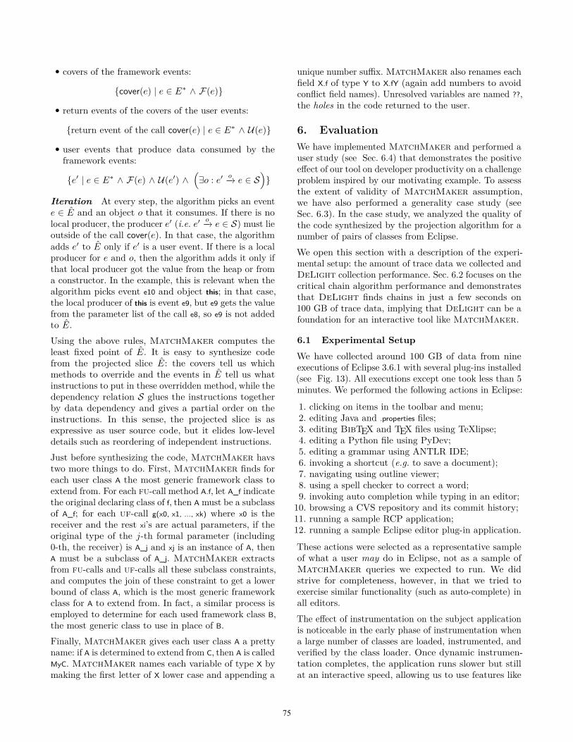
The slice created by MatchMaker contains all thestatements that were necessary to create the criticalchain in a particular heap. However, a lot of the code inthe slice belongs to the framework, and is therefore ofno interest to the user. Additionally, the slice containsmany details that are too specific to a particular example,such as transitive copies of objects through internalfields, or calls to functions internal to the user code.MatchMaker addresses this problem by computinga projected slice that eliminates framework code aswell as superfluous details from the original slice. Theprojection process also has the effect of normalizingthe slices, making it easier to compare the results frommany different traces. Specifically, projection causesmany slices to become identical, and those that remaindifferent usually correspond to different ways of usingthe framework.The essence of the interaction between user and frame-work code is captured by calls that cross the framework-user boundary. Calls from the framework to the user arecalled fu-calls, and calls from the user code to the frame-work are called uf-calls. In the example from Fig. 10, e3and e8 are fu-calls, while e12 is a uf-call; the rest of thecalls, like e9 are termed l-calls, because they stay localto either the framework or the user code (see Fig. 12).fu-calls and uf-calls describe the interaction betweenframework and user: fu-calls tell us which classes toextend and which method to override, while uf-callstell us which APIs to call. The projected slice must
Figure 12. User code and framework interaction.
preserve information about fu-calls and uf-calls as wellas relevant user code, but simplify away the complexityand arbitrariness of the specific sample code from whichthe database was built. For the running example, theprojected slice will indicate that init() must write to fand regViews() must pass the value of f to addView(), butthe fact that this involves a call to getView() is only adetail of this particular example and not relevant in theprojected slice.We first introduce several definitions to talk about thedynamic structure of calls. For any user event e, thecover of e is the latest enclosing fu-call of e. In otherwords, all calls on the stack from cover(e) to e are userl-calls except for cover(e) itself which must reside in theframework code but invoke a user method. For example,in the sample program e3 = cover(e5) and e8 = cover(e10).Dually, we define the cover of a framework event to beits latest enclosing uf-call. We say that an event e isa framework event (written as F(e)) if it is generatedby a statement in the framework code; otherwise, theevent is a user event (or U(e)). The local producer ofa user event e and an object o, consumed by e, is theearliest event that produced object o and has the samecover as e. The local producer is always a user event.For example, the local producer of the object x in e12 ise10 since they have the same cover e8.The projection algorithm takes the set of events Eestablishing the critical chain as a starting point. Ituses the slicing relation S and the function cover, bothprovided by DeLight, to compute the projected sliceE consisting only of user events. The algorithm consistsof two steps: the base step computes the initial set Efrom E and the iteration step expands E to reach theleast fixed point.
Base step First, every user event from E is included:{e | e ∈ E ∧ U(e)}. Next, from the set E∗ = S∗(E) of allevents in the thin slice, the algorithm adds the followinggroups of user events:
74
• covers of the framework events:
{cover(e) | e ∈ E∗ ∧ F(e)}
• return events of the covers of the user events:
{return event of the call cover(e) | e ∈ E∗ ∧ U(e)}
• user events that produce data consumed by theframework events:
{e′ | e ∈ E∗ ∧ F(e) ∧ U(e′) ∧(∃o : e′
o−→ e ∈ S)}
Iteration At every step, the algorithm picks an evente ∈ E and an object o that it consumes. If there is nolocal producer, the producer e′ (i.e. e′
o−→ e ∈ S) must lieoutside of the call cover(e). In that case, the algorithmadds e′ to E only if e′ is a user event. If there is a localproducer for e and o, then the algorithm adds it only ifthat local producer got the value from the heap or froma constructor. In the example, this is relevant when thealgorithm picks event e10 and object this; in that case,the local producer of this is event e9, but e9 gets the valuefrom the parameter list of the call e8, so e9 is not addedto E.Using the above rules, MatchMaker computes theleast fixed point of E. It is easy to synthesize codefrom the projected slice E: the covers tell us whichmethods to override and the events in E tell us whatinstructions to put in these overridden method, while thedependency relation S glues the instructions togetherby data dependency and gives a partial order on theinstructions. In this sense, the projected slice is asexpressive as user source code, but it elides low-leveldetails such as reordering of independent instructions.Just before synthesizing the code, MatchMaker havstwo more things to do. First, MatchMaker finds foreach user class A the most generic framework class toextend from. For each fu-call method A.f, let A_f indicatethe original declaring class of f, then A must be a subclassof A_f; for each uf-call g(x0, x1, ..., xk) where x0 is thereceiver and the rest xi’s are actual parameters, if theoriginal type of the j-th formal parameter (including0-th, the receiver) is A_j and xj is an instance of A, thenA must be a subclass of A_j. MatchMaker extractsfrom fu-calls and uf-calls all these subclass constraints,and computes the join of these constraint to get a lowerbound of class A, which is the most generic frameworkclass for A to extend from. In fact, a similar process isemployed to determine for each used framework class B,the most generic class to use in place of B.Finally, MatchMaker gives each user class A a prettyname: if A is determined to extend from C, then A is calledMyC. MatchMaker names each variable of type X bymaking the first letter of X lower case and appending a
unique number suffix. MatchMaker also renames eachfield X.f of type Y to X.fY (again add numbers to avoidconflict field names). Unresolved variables are named ??,the holes in the code returned to the user.
6. EvaluationWe have implemented MatchMaker and performed auser study (see Sec. 6.4) that demonstrates the positiveeffect of our tool on developer productivity on a challengeproblem inspired by our motivating example. To assessthe extent of validity of MatchMaker assumption,we have also performed a generality case study (seeSec. 6.3). In the case study, we analyzed the quality ofthe code synthesized by the projection algorithm for anumber of pairs of classes from Eclipse.We open this section with a description of the experi-mental setup: the amount of trace data we collected andDeLight collection performance. Sec. 6.2 focuses on thecritical chain algorithm performance and demonstratesthat DeLight finds chains in just a few seconds on100 GB of trace data, implying that DeLight can be afoundation for an interactive tool like MatchMaker.
6.1 Experimental Setup
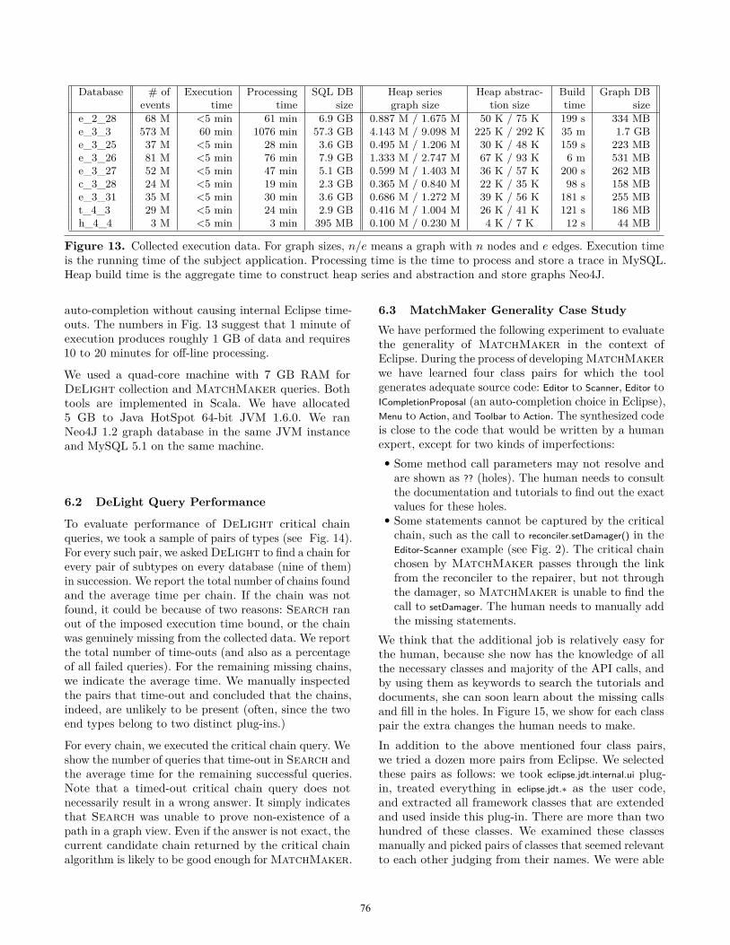
We have collected around 100 GB of data from nineexecutions of Eclipse 3.6.1 with several plug-ins installed(see Fig. 13). All executions except one took less than 5minutes. We performed the following actions in Eclipse:
1. clicking on items in the toolbar and menu;2. editing Java and .properties files;3. editing BibTEX and TEX files using TeXlipse;4. editing a Python file using PyDev;5. editing a grammar using ANTLR IDE;6. invoking a shortcut (e.g. to save a document);7. navigating using outline viewer;8. using a spell checker to correct a word;9. invoking auto completion while typing in an editor;
10. browsing a CVS repository and its commit history;11. running a sample RCP application;12. running a sample Eclipse editor plug-in application.
These actions were selected as a representative sampleof what a user may do in Eclipse, not as a sample ofMatchMaker queries we expected to run. We didstrive for completeness, however, in that we tried toexercise similar functionality (such as auto-complete) inall editors.The effect of instrumentation on the subject applicationis noticeable in the early phase of instrumentation whena large number of classes are loaded, instrumented, andverified by the class loader. Once dynamic instrumen-tation completes, the application runs slower but stillat an interactive speed, allowing us to use features like
75
Database # of Execution Processing SQL DB Heap series Heap abstrac- Build Graph DBevents time time size graph size tion size time size
e_2_28 68 M <5 min 61 min 6.9 GB 0.887 M / 1.675 M 50 K / 75 K 199 s 334 MBe_3_3 573 M 60 min 1076 min 57.3 GB 4.143 M / 9.098 M 225 K / 292 K 35 m 1.7 GBe_3_25 37 M <5 min 28 min 3.6 GB 0.495 M / 1.206 M 30 K / 48 K 159 s 223 MBe_3_26 81 M <5 min 76 min 7.9 GB 1.333 M / 2.747 M 67 K / 93 K 6 m 531 MBe_3_27 52 M <5 min 47 min 5.1 GB 0.599 M / 1.403 M 36 K / 57 K 200 s 262 MBc_3_28 24 M <5 min 19 min 2.3 GB 0.365 M / 0.840 M 22 K / 35 K 98 s 158 MBe_3_31 35 M <5 min 30 min 3.6 GB 0.686 M / 1.272 M 39 K / 56 K 181 s 255 MBt_4_3 29 M <5 min 24 min 2.9 GB 0.416 M / 1.004 M 26 K / 41 K 121 s 186 MBh_4_4 3 M <5 min 3 min 395 MB 0.100 M / 0.230 M 4 K / 7 K 12 s 44 MB
Figure 13. Collected execution data. For graph sizes, n/e means a graph with n nodes and e edges. Execution timeis the running time of the subject application. Processing time is the time to process and store a trace in MySQL.Heap build time is the aggregate time to construct heap series and abstraction and store graphs Neo4J.
auto-completion without causing internal Eclipse time-outs. The numbers in Fig. 13 suggest that 1 minute ofexecution produces roughly 1 GB of data and requires10 to 20 minutes for off-line processing.
We used a quad-core machine with 7 GB RAM forDeLight collection and MatchMaker queries. Bothtools are implemented in Scala. We have allocated5 GB to Java HotSpot 64-bit JVM 1.6.0. We ranNeo4J 1.2 graph database in the same JVM instanceand MySQL 5.1 on the same machine.
6.2 DeLight Query Performance
To evaluate performance of DeLight critical chainqueries, we took a sample of pairs of types (see Fig. 14).For every such pair, we asked DeLight to find a chain forevery pair of subtypes on every database (nine of them)in succession. We report the total number of chains foundand the average time per chain. If the chain was notfound, it could be because of two reasons: Search ranout of the imposed execution time bound, or the chainwas genuinely missing from the collected data. We reportthe total number of time-outs (and also as a percentageof all failed queries). For the remaining missing chains,we indicate the average time. We manually inspectedthe pairs that time-out and concluded that the chains,indeed, are unlikely to be present (often, since the twoend types belong to two distinct plug-ins.)
For every chain, we executed the critical chain query. Weshow the number of queries that time-out in Search andthe average time for the remaining successful queries.Note that a timed-out critical chain query does notnecessarily result in a wrong answer. It simply indicatesthat Search was unable to prove non-existence of apath in a graph view. Even if the answer is not exact, thecurrent candidate chain returned by the critical chainalgorithm is likely to be good enough for MatchMaker.
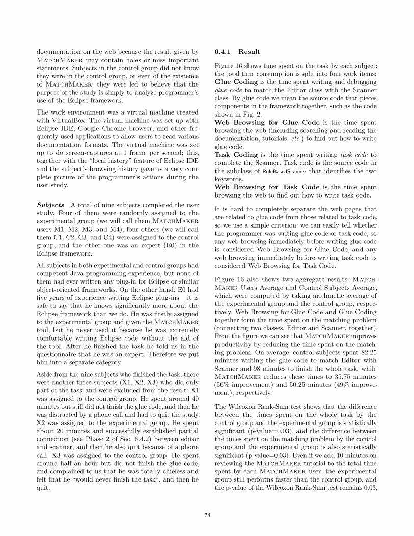
6.3 MatchMaker Generality Case StudyWe have performed the following experiment to evaluatethe generality of MatchMaker in the context ofEclipse. During the process of developing MatchMakerwe have learned four class pairs for which the toolgenerates adequate source code: Editor to Scanner, Editor toICompletionProposal (an auto-completion choice in Eclipse),Menu to Action, and Toolbar to Action. The synthesized codeis close to the code that would be written by a humanexpert, except for two kinds of imperfections:• Some method call parameters may not resolve andare shown as ?? (holes). The human needs to consultthe documentation and tutorials to find out the exactvalues for these holes.
• Some statements cannot be captured by the criticalchain, such as the call to reconciler.setDamager() in theEditor-Scanner example (see Fig. 2). The critical chainchosen by MatchMaker passes through the linkfrom the reconciler to the repairer, but not throughthe damager, so MatchMaker is unable to find thecall to setDamager. The human needs to manually addthe missing statements.
We think that the additional job is relatively easy forthe human, because she now has the knowledge of allthe necessary classes and majority of the API calls, andby using them as keywords to search the tutorials anddocuments, she can soon learn about the missing callsand fill in the holes. In Figure 15, we show for each classpair the extra changes the human needs to make.In addition to the above mentioned four class pairs,we tried a dozen more pairs from Eclipse. We selectedthese pairs as follows: we took eclipse.jdt.internal.ui plug-in, treated everything in eclipse.jdt.∗ as the user code,and extracted all framework classes that are extendedand used inside this plug-in. There are more than twohundred of these classes. We examined these classesmanually and picked pairs of classes that seemed relevantto each other judging from their names. We were able
76
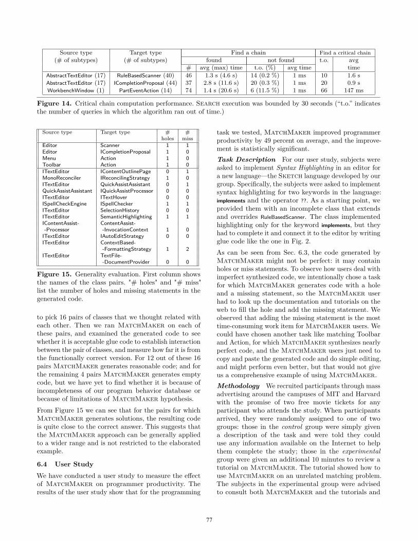
Source type Target type Find a chain Find a critical chain(# of subtypes) (# of subtypes) found not found t.o. avg
# avg (max) time t.o. (%) avg time timeAbstractTextEditor (17) RuleBasedScanner (40) 46 1.3 s (4.6 s) 14 (0.2 %) 1 ms 10 1.6 sAbstractTextEditor (17) ICompletionProposal (44) 37 2.8 s (11.6 s) 20 (0.3 %) 1 ms 20 0.9 sWorkbenchWindow (1) PartEventAction (14) 74 1.4 s (20.6 s) 6 (11.5 %) 1 ms 66 147 ms
Figure 14. Critical chain computation performance. Search execution was bounded by 30 seconds (“t.o.” indicatesthe number of queries in which the algorithm ran out of time.)
Source type Target type # #holes miss
Editor Scanner 1 1Editor ICompletionProposal 1 0Menu Action 1 0Toolbar Action 1 0ITextEditor IContentOutlinePage 0 1MonoReconciler IReconcilingStrategy 1 0ITextEditor QuickAssistAssistant 0 1QuickAssistAssistant IQuickAssistProcessor 0 0ITextEditor ITextHover 0 0ISpellCheckEngine ISpellChecker 1 1ITextEditor SelectionHistory 0 0ITextEditor SemanticHighlighting 1 1IContentAssist- ContentAssist--Processor -InvocationContext 1 0ITextEditor IAutoEditStrategy 0 0ITextEditor ContextBased-
-FormattingStrategy 1 2ITextEditor TextFile-
-DocumentProvider 0 0
Figure 15. Generality evaluation. First column showsthe names of the class pairs. "# holes" and "# miss"list the number of holes and missing statements in thegenerated code.
to pick 16 pairs of classes that we thought related witheach other. Then we ran MatchMaker on each ofthese pairs, and examined the generated code to seewhether it is acceptable glue code to establish interactionbetween the pair of classes, and measure how far it is fromthe functionally correct version. For 12 out of these 16pairs MatchMaker generates reasonable code; and forthe remaining 4 pairs MatchMaker generates emptycode, but we have yet to find whether it is because ofincompleteness of our program behavior database orbecause of limitations of MatchMaker hypothesis.From Figure 15 we can see that for the pairs for whichMatchMaker generates solutions, the resulting codeis quite close to the correct answer. This suggests thatthe MatchMaker approach can be generally appliedto a wider range and is not restricted to the elaboratedexample.
6.4 User StudyWe have conducted a user study to measure the effectof MatchMaker on programmer productivity. Theresults of the user study show that for the programming
task we tested, MatchMaker improved programmerproductivity by 49 percent on average, and the improve-ment is statistically significant.Task Description For our user study, subjects wereasked to implement Syntax Highlighting in an editor fora new language—the Sketch language developed by ourgroup. Specifically, the subjects were asked to implementsyntax highlighting for two keywords in the language:implements and the operator ??. As a starting point, weprovided them with an incomplete class that extendsand overrides RuleBasedScanner. The class implementedhighlighting only for the keyword implements, but theyhad to complete it and connect it to the editor by writingglue code like the one in Fig. 2.As can be seen from Sec. 6.3, the code generated byMatchMaker might not be perfect: it may containholes or miss statements. To observe how users deal withimperfect synthesized code, we intentionally chose a taskfor which MatchMaker generates code with a holeand a missing statement, so the MatchMaker userhad to look up the documentation and tutorials on theweb to fill the hole and add the missing statement. Weobserved that adding the missing statement is the mosttime-consuming work item for MatchMaker users. Wecould have chosen another task like matching Toolbarand Action, for which MatchMaker synthesizes nearlyperfect code, and the MatchMaker users just need tocopy and paste the generated code and do simple editing,and might perform even better, but that would not giveus a comprehensive example of using MatchMaker.Methodology We recruited participants through massadvertising around the campuses of MIT and Harvardwith the promise of two free movie tickets for anyparticipant who attends the study. When participantsarrived, they were randomly assigned to one of twogroups: those in the control group were simply givena description of the task and were told they coulduse any information available on the Internet to helpthem complete the study; those in the experimentalgroup were given an additional 10 minutes to review atutorial on MatchMaker. The tutorial showed how touse MatchMaker on an unrelated matching problem.The subjects in the experimental group were advisedto consult both MatchMaker and the tutorials and
77
documentation on the web because the result given byMatchMaker may contain holes or miss importantstatements. Subjects in the control group did not knowthey were in the control group, or even of the existenceof MatchMaker; they were led to believe that thepurpose of the study is simply to analyze programmer’suse of the Eclipse framework.
The work environment was a virtual machine createdwith VirtualBox. The virtual machine was set up withEclipse IDE, Google Chrome browser, and other fre-quently used applications to allow users to read variousdocumentation formats. The virtual machine was setup to do screen-captures at 1 frame per second; this,together with the “local history” feature of Eclipse IDEand the subject’s browsing history gave us a very com-plete picture of the programmer’s actions during theuser study.
Subjects A total of nine subjects completed the userstudy. Four of them were randomly assigned to theexperimental group (we will call them MatchMakerusers M1, M2, M3, and M4), four others (we will callthem C1, C2, C3, and C4) were assigned to the controlgroup, and the other one was an expert (E0) in theEclipse framework.
All subjects in both experimental and control groups hadcompetent Java programming experience, but none ofthem had ever written any plug-in for Eclipse or similarobject-oriented frameworks. On the other hand, E0 hadfive years of experience writing Eclipse plug-ins – it issafe to say that he knows significantly more about theEclipse framework than we do. He was firstly assignedto the experimental group and given the MatchMakertool, but he never used it because he was extremelycomfortable writing Eclipse code without the aid ofthe tool. After he finished the task he told us in thequestionnaire that he was an expert. Therefore we puthim into a separate category.
Aside from the nine subjects who finished the task, therewere another three subjects (X1, X2, X3) who did onlypart of the task and were excluded from the result: X1was assigned to the control group. He spent around 40minutes but still did not finish the glue code, and then hewas distracted by a phone call and had to quit the study.X2 was assigned to the experimental group. He spentabout 20 minutes and successfully established partialconnection (see Phase 2 of Sec. 6.4.2) between editorand scanner, and then he also quit because of a phonecall. X3 was assigned to the control group. He spentaround half an hour but did not finish the glue code,and complained to us that he was totally clueless andfelt that he “would never finish the task”, and then hequit.
6.4.1 Result
Figure 16 shows time spent on the task by each subject;the total time consumption is split into four work items:Glue Coding is the time spent writing and debuggingglue code to match the Editor class with the Scannerclass. By glue code we mean the source code that piecescomponents in the framework together, such as the codeshown in Fig. 2.Web Browsing for Glue Code is the time spentbrowsing the web (including searching and reading thedocumentation, tutorials, etc.) to find out how to writeglue code.Task Coding is the time spent writing task code tocomplete the Scanner. Task code is the source code inthe subclass of RuleBasedScanner that identifies the twokeywords.Web Browsing for Task Code is the time spentbrowsing the web to find out how to write task code.
It is hard to completely separate the web pages thatare related to glue code from those related to task code,so we use a simple criterion: we can easily tell whetherthe programmer was writing glue code or task code, soany web browsing immediately before writing glue codeis considered Web Browsing for Glue Code, and anyweb browsing immediately before writing task code isconsidered Web Browsing for Task Code.
Figure 16 also shows two aggregate results: Match-Maker Users Average and Control Subjects Average,which were computed by taking arithmetic average ofthe experimental group and the control group, respec-tively. Web Browsing for Glue Code and Glue Codingtogether form the time spent on the matching problem(connecting two classes, Editor and Scanner, together).From the figure we can see that MatchMaker improvesproductivity by reducing the time spent on the match-ing problem. On average, control subjects spent 82.25minutes writing the glue code to match Editor withScanner and 98 minutes to finish the whole task, whileMatchMaker reduces these times to 35.75 minutes(56% improvement) and 50.25 minutes (49% improve-ment), respectively.
The Wilcoxon Rank-Sum test shows that the differencebetween the times spent on the whole task by thecontrol group and the experimental group is statisticallysignificant (p-value=0.03), and the difference betweenthe times spent on the matching problem by the controlgroup and the experimental group is also statisticallysignificant (p-value=0.03). Even if we add 10 minutes onreviewing the MatchMaker tutorial to the total timespent by each MatchMaker user, the experimentalgroup still performs faster than the control group, andthe p-value of the Wilcoxon Rank-Sum test remains 0.03,
78
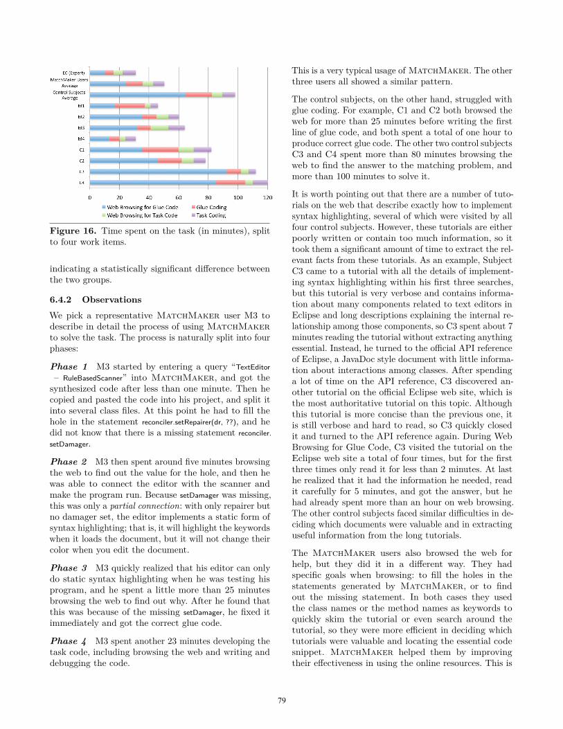
Figure 16. Time spent on the task (in minutes), splitto four work items.
indicating a statistically significant difference betweenthe two groups.
6.4.2 Observations
We pick a representative MatchMaker user M3 todescribe in detail the process of using MatchMakerto solve the task. The process is naturally split into fourphases:
Phase 1 M3 started by entering a query “TextEditor– RuleBasedScanner” into MatchMaker, and got thesynthesized code after less than one minute. Then hecopied and pasted the code into his project, and split itinto several class files. At this point he had to fill thehole in the statement reconciler.setRepairer(dr, ??), and hedid not know that there is a missing statement reconciler.setDamager.
Phase 2 M3 then spent around five minutes browsingthe web to find out the value for the hole, and then hewas able to connect the editor with the scanner andmake the program run. Because setDamager was missing,this was only a partial connection: with only repairer butno damager set, the editor implements a static form ofsyntax highlighting; that is, it will highlight the keywordswhen it loads the document, but it will not change theircolor when you edit the document.
Phase 3 M3 quickly realized that his editor can onlydo static syntax highlighting when he was testing hisprogram, and he spent a little more than 25 minutesbrowsing the web to find out why. After he found thatthis was because of the missing setDamager, he fixed itimmediately and got the correct glue code.
Phase 4 M3 spent another 23 minutes developing thetask code, including browsing the web and writing anddebugging the code.
This is a very typical usage of MatchMaker. The otherthree users all showed a similar pattern.
The control subjects, on the other hand, struggled withglue coding. For example, C1 and C2 both browsed theweb for more than 25 minutes before writing the firstline of glue code, and both spent a total of one hour toproduce correct glue code. The other two control subjectsC3 and C4 spent more than 80 minutes browsing theweb to find the answer to the matching problem, andmore than 100 minutes to solve it.
It is worth pointing out that there are a number of tuto-rials on the web that describe exactly how to implementsyntax highlighting, several of which were visited by allfour control subjects. However, these tutorials are eitherpoorly written or contain too much information, so ittook them a significant amount of time to extract the rel-evant facts from these tutorials. As an example, SubjectC3 came to a tutorial with all the details of implement-ing syntax highlighting within his first three searches,but this tutorial is very verbose and contains informa-tion about many components related to text editors inEclipse and long descriptions explaining the internal re-lationship among those components, so C3 spent about 7minutes reading the tutorial without extracting anythingessential. Instead, he turned to the official API referenceof Eclipse, a JavaDoc style document with little informa-tion about interactions among classes. After spendinga lot of time on the API reference, C3 discovered an-other tutorial on the official Eclipse web site, which isthe most authoritative tutorial on this topic. Althoughthis tutorial is more concise than the previous one, itis still verbose and hard to read, so C3 quickly closedit and turned to the API reference again. During WebBrowsing for Glue Code, C3 visited the tutorial on theEclipse web site a total of four times, but for the firstthree times only read it for less than 2 minutes. At lasthe realized that it had the information he needed, readit carefully for 5 minutes, and got the answer, but hehad already spent more than an hour on web browsing.The other control subjects faced similar difficulties in de-ciding which documents were valuable and in extractinguseful information from the long tutorials.
The MatchMaker users also browsed the web forhelp, but they did it in a different way. They hadspecific goals when browsing: to fill the holes in thestatements generated by MatchMaker, or to findout the missing statement. In both cases they usedthe class names or the method names as keywords toquickly skim the tutorial or even search around thetutorial, so they were more efficient in deciding whichtutorials were valuable and locating the essential codesnippet. MatchMaker helped them by improvingtheir effectiveness in using the online resources. This is
79
supported by the data: MatchMaker users spent 24.25minutes on Web Browsing for Glue Code, comparedto 64.5 minutes on average of control subjects. TheWilcoxon test shows that the difference is statisticallysignificant (with p-value=0.04).The framework expert was different from subjects inboth control and experimental groups: he knew exactlywhat he was looking for on the web and found it veryquickly, so he could finish glue code in 16 minutes.Overall, our observations from the subjects allow us todraw some preliminary conclusions.• The matching problem is indeed a significant problemwhen writing code on top of complex frameworks.This is particularly true for people who are new tothe framework, and less so for experts.
• Tutorials and documentation available online are notenough to close the gap between novices and experts.The class-by-class documentation available throughJavaDoc is particularly unhelpful because it fails todescribe multi-object interactions. Tutorials, in turn,can be unreliable because of errors and omissions,but the most important problem is the sheer amountof data that a novice has to read before beginning tounderstand the framework.
• MatchMaker has a statistically significant impacton programmer productivity by showing programmersthe object interactions that are necessary to achievea task. This is true even when the tool fails to give acomplete solution to the task in question.
7. Related workThe idea of using large corpus of data for programunderstanding has seen many incarnations in the pastfew years. Prospector [9], XSnippet [13], MAPO [20],PARSEWeb [17], and Strathcona [7] mine source coderepositories and assist programmers in common tasks:finding call sequences to derive an object of one typefrom an object of another type, complex initializationpatterns, and frequent API usage patterns. They do soby computing relevant code snippets as determined bythe static program context and then applying heuristicsto rank them. Since they primarily utilize static analysis,the context lacks heap connectivity information. Thesetools are geared towards code assistance and do notproduce full templates of the program that may spanmultiple classes.Whyline [8] combines source code analysis with dynamicanalysis to assist debugging by tracing input/outputevents together with the program, and suggesting ques-tions that relate external observations to internal methodcalls. DeLight could potentially serve as a commonframework for tools like Whyline and MatchMaker
that need to query program executions. MatchMakerdoes not use external observations (GUI or input events)to locate points of interest in the trace, instead it usesinternal heap configuration to identify important eventsin the trace.PQL [10] proposes a query language for analyzing pro-gram execution statically or dynamically. It is aimed atfinding design defects in the code and as such requiresdetailed knowledge of the code. It is not suitable forprogram understanding tasks. PTQL [4] uses its ownrelational query language to instrument a program anddynamically query live executions. FUDA [6] is closelyrelated in its goal of producing program templates fromexample traces. Like our system, this tool also lever-ages the distinction between user and framework codeto project slices. However, the API trace slicing used inFUDA only uses shared objects in argument lists of callsto detect dependencies in the heap. FUDA does not keeptrack of the heap updates. All of the above tools relyon light-weight dynamic analysis and as such, requiremanual effort in formulating queries in a specialized lan-guage or instrumenting programs specifically for thesequeries. MatchMaker attempts to reuse databases foranswering all queries, while keeping the query languagevery simple.BugNet [11] and similar tools record the full programtrace for deterministic replay debugging. MatchMakerdoes not collect entire execution data. It uses just enoughinformation from the trace to be able to answer programsynthesis-related queries effectively.Program synthesis systems such as SKETCH [14] canproduce program text from a slower version of thesame program or its specification via a combinatorialsearch over ASTs. The level of deep static reasoningabout program that is needed by SKETCH has notbeen achieved for the large scale software like Eclipse.Moreover, the dynamic features that are prevalent inEclipse and its scale make it very hard to employ anystatic reasoning except for the very light-weight.The projection algorithm in Sec. 5.2 is an instance ofdynamic amorphous program slicing [5]. Like traditionalprogram slicing, amorphous slicing simplifies a programwhile preserving a projection of its semantics. Unliketraditional program slicing that only allows picking asubset of the program, amorphous slicing may use anysimplifying transformation. The projection algorithmused by MatchMaker is amorphous because it linksconsumer events directly to their local producers.
8. ConclusionWe have presented a new approach to synthesis basedon the analysis of very large amounts of program ex-ecution data. The approach is made possible by the
80
DeLight system, which allows for the efficient collec-tion, management and analysis of this data. DeLightuses abstraction to support detailed queries about howthe heap evolves as the program executes, which arenecessary to support our synthesis algorithm.Our synthesis algorithm focuses on the problem ofgenerating the glue code necessary for two classes tointeract with each other. This glue code often involvesinstantiating new classes, making API calls, and evenoverriding methods in specific classes, and our toolMatchMaker can support all of these actions.Our empirical evaluation shows that writing this gluecode is especially time consuming for novice program-mers, and that MatchMaker can significantly improvetheir productivity. It also shows that MatchMaker isgeneral enough to handle many interesting queries, andproduces code that can be used by programmers withvery few changes.
Acknowledgement We would like to give specialthanks to Professor Greg Morrisett for helping us con-duct part of the user study at Harvard University. Wewould also like to thank the participants in our user study.This research was supported by the National ScienceFoundation grant CCF-1049406 and by MIT’s ComputerScience and Artificial Intelligence Lab (CSAIL).
References[1] E. Bruneton, R. Lenglet, and T. Coupaye. ASM: acode manipulation tool to implement adaptable systems.Adaptable and extensible component systems, 2002.
[2] A. Diwan, K. S. McKinley, and J. E. B. Moss. Type-basedalias analysis. PLDI ’98, pages 106–117, New York, NY,USA, 1998. ACM.
[3] Eclipse. Helios release notes, 2010.[4] S. F. Goldsmith, R. O’Callahan, and A. Aiken. Relationalqueries over program traces. OOPSLA ’05, pages 385–402,New York, NY, USA, 2005. ACM.
[5] M. Harman, D. Binkley, and S. Danicic. Amorphousprogram slicing. J. Syst. Softw., 68:45–64, October 2003.
[6] A. Heydarnoori, K. Czarnecki, and T. T. Bartolomei.Supporting framework use via automatically extractedconcept-implementation templates. In Proceedings of the23rd European Conference on ECOOP 2009 — Object-Oriented Programming, Genoa, pages 344–368, Berlin,Heidelberg, 2009. Springer-Verlag.
[7] R. Holmes and G. C. Murphy. Using structural contextto recommend source code examples. ICSE ’05, pages117–125, New York, NY, USA, 2005. ACM.
[8] A. J. Ko and B. A. Myers. Debugging reinvented: askingand answering why and why not questions about programbehavior. ICSE ’08, pages 301–310, New York, NY, USA,2008. ACM.
[9] D. Mandelin, L. Xu, R. Bodík, and D. Kimelman. Jungloidmining: helping to navigate the api jungle. PLDI ’05,pages 48–61, New York, NY, USA, 2005. ACM.
[10] M. Martin, B. Livshits, and M. S. Lam. Findingapplication errors and security flaws using pql: a programquery language. OOPSLA ’05, pages 365–383, New York,NY, USA, 2005. ACM.
[11] S. Narayanasamy, G. Pokam, and B. Calder. Bugnet:Continuously recording program execution for determinis-tic replay debugging. ISCA ’05, pages 284–295,Washington,DC, USA, 2005. IEEE Computer Society.
[12] Neo4J. Home page, 2011.[13] N. Sahavechaphan and K. Claypool. Xsnippet: miningfor sample code. OOPSLA ’06, pages 413–430, New York,NY, USA, 2006. ACM.
[14] A. Solar-Lezama, L. Tancau, R. Bodik, S. Seshia, andV. Saraswat. Combinatorial sketching for finite programs.ASPLOS-XII, pages 404–415, New York, NY, USA, 2006.ACM.
[15] M. Sridharan, S. J. Fink, and R. Bodik. Thin slicing.PLDI ’07, pages 112–122, New York, NY, USA, 2007.ACM.
[16] S. Srivastava, S. Gulwani, and J. S. Foster. Fromprogram verification to program synthesis. POPL ’10,pages 313–326, New York, NY, USA, 2010. ACM.
[17] S. Thummalapenta and T. Xie. Parseweb: a programmerassistant for reusing open source code on the web. ASE’07, pages 204–213, New York, NY, USA, 2007. ACM.
[18] M. Vechev and E. Yahav. Deriving linearizable fine-grained concurrent objects. PLDI ’08, pages 125–135, NewYork, NY, USA, 2008. ACM.
[19] G. Xu, N. Mitchell, M. Arnold, A. Rountev, E. Schonberg,and G. Sevitsky. Finding low-utility data structures. PLDI’10, pages 174–186, New York, NY, USA, 2010. ACM.
[20] H. Zhong, T. Xie, L. Zhang, J. Pei, and H. Mei. MAPO:Mining and recommending API usage patterns. ECOOP2009–Object-Oriented Programming, pages 318–343, 2009.
81