Embed Size (px)
Citation preview

Product Brochure
Data Quality AnalyzerMD1230B

2 Product Brochure l MD1230B
The MD1230B Data Quality Analyzer is a group of IP/Ethernet measuring instruments covering the increasingly active field of next-generation networks. The family supports the full range of access and metro network applications, including PON system verification, IP network equipment evaluation, network QoS verification, and IPTV streaming service verification. In addition, the products combine all the functions required for performance evaluation of IP network equipment and network systems in all-in-one platform, offering a high-efficiency measurement environment with integrated operations. The MD1230B is the Anritsu solution of choice for all your next-generation network measurement needs.
1. IP Network Equipment Evaluation
(1) High-density Switch Performance Evaluation(2) Automated Switch Performance Measurement(3) Interoperability Verification(4) Physical Layer Measurement
2. Network System Verification
(1) PON System Verification(2) IPTV Streaming Service Verification(3) Carrier Class Network Service Verification
Versatile Applications
MD1230BData Quality Analyzer

Product Brochure l MD1230B 3
Application Examples
High-Density Switch Performance MeasurementsOne MD1230B unit supports control and measurement of up to 60 ports, respectively. Therefore, all 48 ports of the highest-density 1U switch can be load-tested simultaneously, providing a small footprint, cost savings, and effective return on investment.
1. IP Network Equipment Evaluation
Automatic Switch Performance MeasurementOne-button, IETF RFC 2544 and RFC 2889-compliant automatic performance testing [Option 10] supports automatic display of measurement results, shortening evaluation times and improving work efficiency.
Connection VerificationThe following functions make network configuration pre-verification interoperability checks and fault troubleshooting easier, while elimination of link faults improves network connection reliability.
<Link Test>Repeatedly forcing the link on and off permits verification of equipment operation during a Link Flap situation.
<Auto Negotiation Analysis> [Option 15]The auto negotiation connection status is easily analyzed using the Sequence Capture and Decode functions to improve the validity of interoperability test verification.
Physical Layer MeasurementsVerification of signal transmission quality is key to improving network reliability. The variable measurement clock (±100 ppm) and clock monitoring functions of the Clock Measurement Option [MU120131A/ 132A/138A-01], as well as the error insertion and error measurement functions of the BER Measurement Option [Option 11], support this verification to assure high-reliability operation at the equipment physical layer.
Error Insertion
VLAN networks are supported as well.
RFC 2544 Throughput Result
RFC 2889 Result
MD1230B
MD1230B
MD1230B
MD1230B
4 Product Brochure l MD1230B
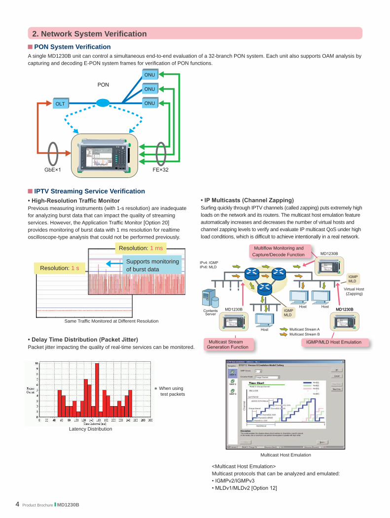
PON System VerificationA single MD1230B unit can control a simultaneous end-to-end evaluation of a 32-branch PON system. Each unit also supports OAM analysis by capturing and decoding E-PON system frames for verification of PON functions.
2. Network System Verification
IPTV Streaming Service Verification• High-Resolution Traffic MonitorPrevious measuring instruments (with 1-s resolution) are inadequate for analyzing burst data that can impact the quality of streaming services. However, the Application Traffic Monitor [Option 20] provides monitoring of burst data with 1 ms resolution for realtime oscilloscope-type analysis that could not be performed previously.
• IP Multicasts (Channel Zapping) Surfing quickly through IPTV channels (called zapping) puts extremely high loads on the network and its routers. The multicast host emulation feature automatically increases and decreases the number of virtual hosts and channel zapping levels to verify and evaluate IP multicast QoS under high load conditions, which is difficult to achieve intentionally in a real network.
<Multicast Host Emulation>Multicast protocols that can be analyzed and emulated:• IGMPv2/IGMPv3• MLDv1/MLDv2 [Option 12]
Multicast Host Emulation
• Delay Time Distribution (Packet Jitter) Packet jitter impacting the quality of real-time services can be monitored.
Latency Distribution
* When using test packets
Resolution: 1 s
Resolution: 1 ms
Supports monitoring of burst data
Virtual Host (Zapping)
Multicast Stream Generation Function
IGMP/MLD Host Emulation
Multiflow Monitoring and Capture/Decode Function
Same Traffic Monitored at Different Resolution

Product Brochure l MD1230B 5
Carrier Class Network Service Verification• Multiflow Counter QoS Priority Control VerificationEmulating high-load conditions and monitoring individual traffic flows under these conditions enables pre-commissioning QoS evaluation and verification.
<Stream Generation>Full-wire-rate, high-load traffic can be generated easily, something that is difficult to do intentionally on a real network. Using the stream editing functions supports flexible setting of QoS-related parameters.
<Multiflow Counter>Simultaneous monitoring of every traffic condition (throughout/delay/frame loss) enables verification of QoS controls and measurement of QoS efficiency. Templates with various priority parameters, including MAC, VLAN, IP, and TCP/UDP port number, are provided.
Stream Generation
Flow Definitions (Priority Parameters)
• Ethernet OAM Function VerificationThe Ethernet OAM Protocol Emulation Function [Option 28] imitates equipment supporting Ethernet OAM (MEP) for evaluation and verification of networks and network equipment.
*: Enabled with MU120131A 10/100/1000M Ethernet Module,MU120132A Gigabit Ethernet Module and MU120138A 10 Gigabit Ethernet Module
• Protocol AnalysisIn addition to the standard protocol decoding functions, installing the Ethereal®/Wireshark® supports more detailed analysis of captured data.
* Ethereal® is registered trademarks of Ethereal, Inc.* Wireshark® is registered trademarks of Gerald Combs.
<Ethernet OAM Protocol Emulation>Supports ITU-T Y.1731 and IEEE 802.1agCCM periodic send*; LBM/LTM response*; RDI addition*; LOC/AIS/RDI detection*; and OAM frame send and protocol analysis of captured frame
Congestion
Multiflow Counter
6 Product Brochure l MD1230B
Useful Functions
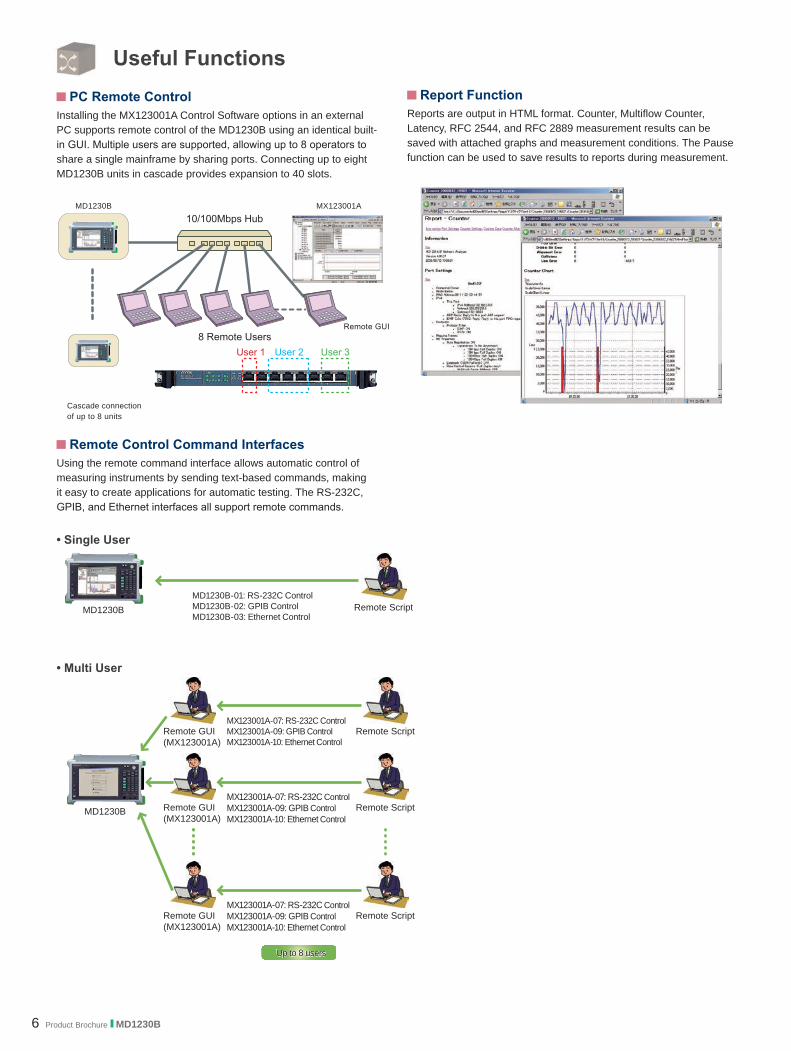
Remote Control Command InterfacesUsing the remote command interface allows automatic control of measuring instruments by sending text-based commands, making it easy to create applications for automatic testing. The RS-232C, GPIB, and Ethernet interfaces all support remote commands.
Report FunctionReports are output in HTML format. Counter, Multiflow Counter, Latency, RFC 2544, and RFC 2889 measurement results can be saved with attached graphs and measurement conditions. The Pause function can be used to save results to reports during measurement.
Cascade connection of up to 8 units
PC Remote ControlInstalling the MX123001A Control Software options in an external PC supports remote control of the MD1230B using an identical built-in GUI. Multiple users are supported, allowing up to 8 operators to share a single mainframe by sharing ports. Connecting up to eight MD1230B units in cascade provides expansion to 40 slots.
Remote GUI
MX123001AMD1230B
• Single User
Remote ScriptMD1230BMD1230B-01: RS-232C ControlMD1230B-02: GPIB ControlMD1230B-03: Ethernet Control
MD1230B Remote GUI(MX123001A)
Remote Script
Remote GUI(MX123001A)
Remote Script
Remote GUI(MX123001A)
Remote Script
Up to 8 usersUp to 8 users
MX123001A-07: RS-232C ControlMX123001A-09: GPIB ControlMX123001A-10: Ethernet Control
MX123001A-07: RS-232C ControlMX123001A-09: GPIB ControlMX123001A-10: Ethernet Control
MX123001A-07: RS-232C ControlMX123001A-09: GPIB ControlMX123001A-10: Ethernet Control
• Multi User

Product Brochure l MD1230B 7
FunctionsModel MU120131A MU120132A MU120138AInterface 10/100/1000BASE-T 1000BASE-X 10GBASE-RPorts (Connector) 12 (RJ-45) 8 (SFP) 4 (SFP+)Clock Variation *1
*1*1
Link Flap *2
Auto MDI/MDI-X Frame GenerationStream Generation (Tx Stream) Multi-Layer VLAN MAC Address Increment IP Address Increment TCP/UDP Port Number Increment Spanning Tree/Link Aggregation Frame (Option 23) Test Frame Addition Hardware Random Pattern MeasurementCounter Multi-Flow Counter Capture Decode Latency Ping Ping6 (Option 12) Arrival Time Variation/Latency Variation Through Mode Monitor Mode Address Swap Mode Unframe BER Test Packet BER Test (Option 11) Auto Negotiation Analysis (Option 15)*3 Application Traffic Monitor (Option 20) Link Fault Signalling (Module Option 03) *4
Clock Measurement *1*1
*1
PoE (Module Option 02) Ethernet OAM (Option 28) Automatic Test RFC 2544 with VLAN RFC 2889 with VLAN (Option 10) Protocol EmulationARP ICMP ICMPv6 (Option 12) IGMPv2/IGMPv3 IGAP (Option 14) MLD/MLDv2 (Option 12) MLDA (Option 22)*5
*1: Requires MU120131A/32A-01 Clock Measurement option*2: Excludes No/Go Check*3: Supports SX/LX/LE/LR for SFP*4: Requires MU120138A-03 Link Fault Signalling option*5: Requires IPv6 Expansion (Option 12)

8 Product Brochure l MD1230B
Selection Guide Module Slots
Installed Module CombinationsModel/Order No. Name No. of Slots Required No. of Ports Max. No. Modules Supported SlotsMU120131A 10/100/1000M Ethernet Module 1 12 5 1 to 5MU120132A Gigabit Ethernet Module 1 8 5 1 to 5MU120138A 10 Gigabit Ethernet Module 1 4 5 1 to 5
Mainframe OptionsModel/Order No. Name
MD1230B-01 RS-232C ControlMD1230B-02 GPIB ControlMD1230B-03 Ethernet ControlMD1230B-10 RFC 2889 Benchmarking TestMD1230B-11 Packet BER TestMD1230B-12 IPv6 ExpansionMD1230B-14 IGAP ProtocolMD1230B-15 Auto Negotiation AnalysisMD1230B-20 Application Traffic MonitorMD1230B-22 MLDA Protocol*MD1230B-23 Spanning Tree/Link AggregationMD1230B-28 Ethernet OAM
*: Requires Option 12 IPv6 Expansion
Module OptionsModel/Order No. Name
MU120131A-01, MU120132A-01, MU120138A-01
Clock Measurement
MU120131A-02 PoEMU120138A-03 Link Fault Signalling
Slot 1Slot 2Slot 3Slot 4Slot 5
* The MD1230B is a 5-slot model accepting up to five measurement modules.MD1230B
Product Brochure l MD1230B 9
Specifications
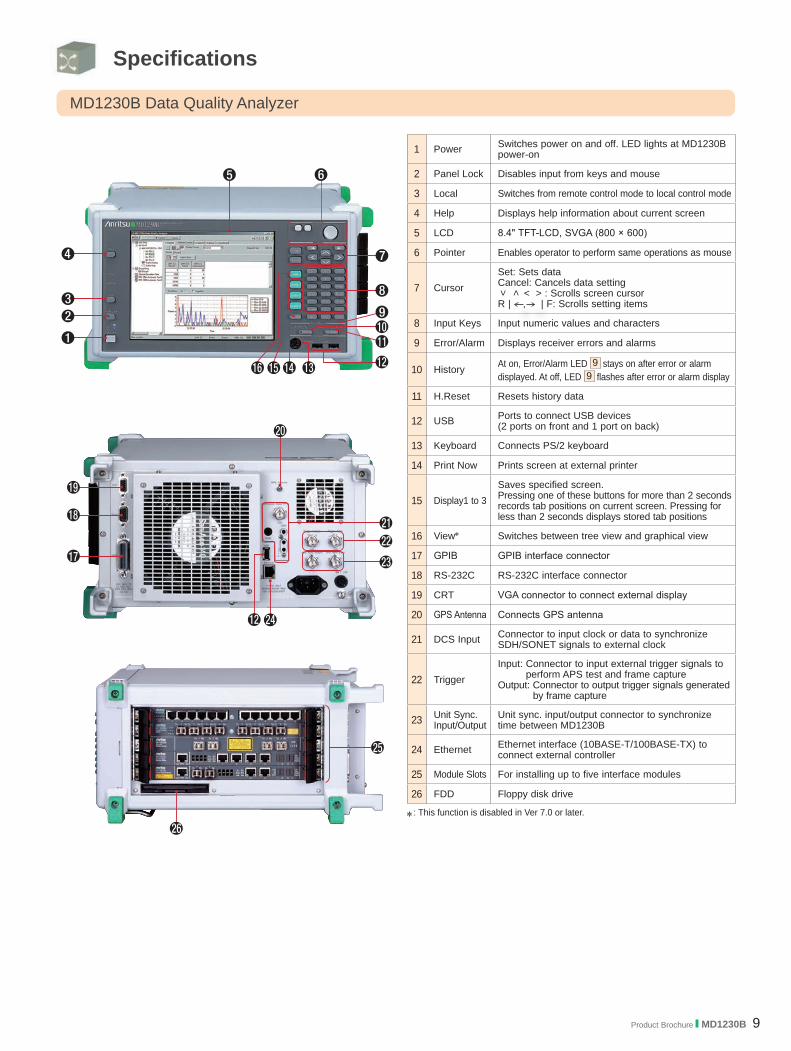
MD1230B Data Quality Analyzer
1 Power Switches power on and off. LED lights at MD1230B power-on
2 Panel Lock Disables input from keys and mouse
3 Local Switches from remote control mode to local control mode
4 Help Displays help information about current screen
5 LCD 8.4" TFT-LCD, SVGA (800 × 600)
6 Pointer Enables operator to perform same operations as mouse
7 CursorSet: Sets dataCancel: Cancels data setting
< > < > : Scrolls screen cursorR | , | F: Scrolls setting items
8 Input Keys Input numeric values and characters
9 Error/Alarm Displays receiver errors and alarms
10 History At on, Error/Alarm LED 9 stays on after error or alarmdisplayed. At off, LED 9 flashes after error or alarm display
11 H.Reset Resets history data
12 USB Ports to connect USB devices (2 ports on front and 1 port on back)
13 Keyboard Connects PS/2 keyboard
14 Print Now Prints screen at external printer
15 Display1 to 3Saves specified screen. Pressing one of these buttons for more than 2 seconds records tab positions on current screen. Pressing for less than 2 seconds displays stored tab positions
16 View* Switches between tree view and graphical view
17 GPIB GPIB interface connector
18 RS-232C RS-232C interface connector
19 CRT VGA connector to connect external display
20 GPS Antenna Connects GPS antenna
21 DCS Input Connector to input clock or data to synchronize SDH/SONET signals to external clock
22 TriggerInput: Connector to input external trigger signals to
perform APS test and frame captureOutput: Connector to output trigger signals generated
by frame capture
23 Unit Sync. Input/Output
Unit sync. input/output connector to synchronize time between MD1230B
24 Ethernet Ethernet interface (10BASE-T/100BASE-TX) to connect external controller
25 Module Slots For installing up to five interface modules
26 FDD Floppy disk drive
*: This function is disabled in Ver 7.0 or later.

10 Product Brochure l MD1230B
MD1230B Mainframe SpecificationsModel MD1230B Data Quality Analyzer
IndicatorLCD 8.4", Color TFT, SVGA (800 × 600) LED Power, HDD, Remote, Panel Lock, Power Fail, Error, Alarm, History
OS Windows® XP ProfessionalStorage Unit HDD and 3.5" FDD
Interface
RS-232C, GPIB, Ethernet (RJ-45), USB1.1 × 3 ports, Keyboard (PS/2), GPS antenna, CRT (15-pin mini D-sub)
Trigger
Trigger Input: For APS test and frame captureTrigger Output: Capture triggerLevel: TTL (Active High) Connector: BNC (75 Ω)
Unit Sync.Input/Output
Time Synchronization for MD1230BLevel: TTLConnector: BNC (75 Ω)
DCS Input
FrequencyClock: 1.544 MHz, 2.048 MHz, 64 kHz + 8 kHzData: 1.544 Mbit/s, 2.048 Mbit/sInput Range: ±50 ppm
Level/Code1.544 M: ANSI T1.403 (B8ZS) 2.048 M: ITU-T G.703 Table 10 (HDB3) 64 kHz + 8 kHz: 0.63 to 1.1 Vo-p (AMI, 8 kHz violation)
Connector2.048 MHz, 2.048 Mbit/s: BNC (75 Ω) 2.048 MHz, 2.048 Mbit/s, 64 kHz + 8 kHz: Siemens (120 Ω balanced) 1.544 MHz, 1.544 Mbit/s: BANTAM (100 Ω balanced)
Remote Control Remote control using LAN (10BASE-T/100BASE-TX) with MX123001ARemote command control with RS-232C (Option 01) or GPIB (Option 02) or LAN (10BASE-T/100BASE-Tx, Option 03)
Input Device Pointing device, front keysPower 100 to 120/200 to 240 Vac (autoswitching), 50 Hz to 60 HzPower Consumption ≤650 VAOperational Temperature and Humidity +5° to +40˚C, +20 to +80%
Dimensions and Mass 320 (W) × 177 (H) × 350 (D) mm, ≤15 kg (excluding options and plug-in modules) EMC EN 61326-1, EN 61000-3-2LVD EN 61010-1Laser Safety Depends on installed module. Refer to the safety standards for each module.Number of Slots 5
*: See the selection guide and ordering information for supported modules and options.*: Windows® is a registered trademark of Microsoft Corporation in the USA and other countries.
Product Brochure l MD1230B 11
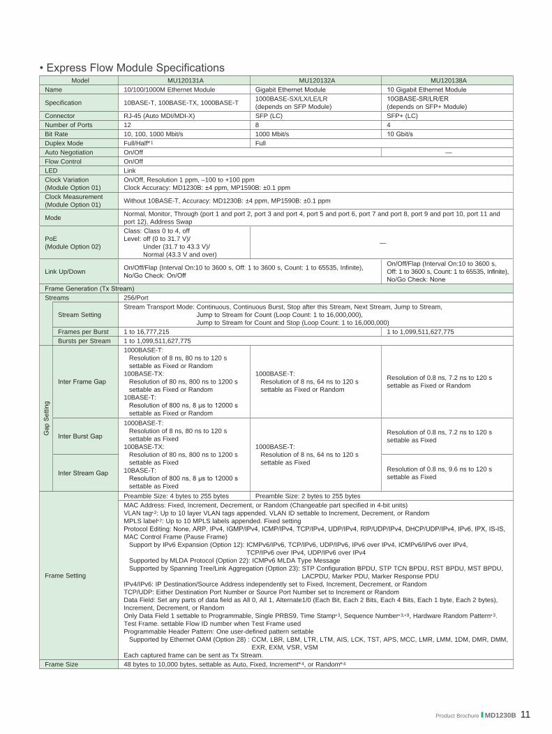
• Express Flow Module SpecificationsModel MU120131A MU120132A MU120138A
Name 10/100/1000M Ethernet Module Gigabit Ethernet Module 10 Gigabit Ethernet Module
Specification 10BASE-T, 100BASE-TX, 1000BASE-T 1000BASE-SX/LX/LE/LR (depends on SFP Module)
10GBASE-SR/LR/ER (depends on SFP+ Module)
Connector RJ-45 (Auto MDI/MDI-X) SFP (LC) SFP+ (LC) Number of Ports 12 8 4Bit Rate 10, 100, 1000 Mbit/s 1000 Mbit/s 10 Gbit/sDuplex Mode Full/Half*1 FullAuto Negotiation On/Off —Flow Control On/OffLED LinkClock Variation(Module Option 01)
On/Off, Resolution 1 ppm, –100 to +100 ppmClock Accuracy: MD1230B: ±4 ppm, MP1590B: ±0.1 ppm
Clock Measurement (Module Option 01) Without 10BASE-T, Accuracy: MD1230B: ±4 ppm, MP1590B: ±0.1 ppm
Mode Normal, Monitor, Through (port 1 and port 2, port 3 and port 4, port 5 and port 6, port 7 and port 8, port 9 and port 10, port 11 and port 12), Address Swap
PoE (Module Option 02)
Class: Class 0 to 4, off Level: off (0 to 31.7 V)/
Under (31.7 to 43.3 V)/ Normal (43.3 V and over)
—
Link Up/Down On/Off/Flap (Interval On:10 to 3600 s, Off: 1 to 3600 s, Count: 1 to 65535, Infinite), No/Go Check: On/Off
On/Off/Flap (Interval On:10 to 3600 s, Off: 1 to 3600 s, Count: 1 to 65535, Infinite), No/Go Check: None
Frame Generation (Tx Stream) Streams 256/Port
Stream SettingStream Transport Mode: Continuous, Continuous Burst, Stop after this Stream, Next Stream, Jump to Stream,
Jump to Stream for Count (Loop Count: 1 to 16,000,000), Jump to Stream for Count and Stop (Loop Count: 1 to 16,000,000)
Frames per Burst 1 to 16,777,215 1 to 1,099,511,627,775Bursts per Stream 1 to 1,099,511,627,775
Gap
Set
ting
Inter Frame Gap
1000BASE-T: Resolution of 8 ns, 80 ns to 120 s settable as Fixed or Random
100BASE-TX: Resolution of 80 ns, 800 ns to 1200 s settable as Fixed or Random
10BASE-T: Resolution of 800 ns, 8 μs to 12000 s settable as Fixed or Random
1000BASE-T: Resolution of 8 ns, 64 ns to 120 s settable as Fixed or Random
Resolution of 0.8 ns, 7.2 ns to 120 s settable as Fixed or Random
Inter Burst Gap
1000BASE-T: Resolution of 8 ns, 80 ns to 120 s settable as Fixed
100BASE-TX: Resolution of 80 ns, 800 ns to 1200 s settable as Fixed
10BASE-T: Resolution of 800 ns, 8 μs to 12000 s settable as Fixed
1000BASE-T:Resolution of 8 ns, 64 ns to 120 s settable as Fixed
Resolution of 0.8 ns, 7.2 ns to 120 s settable as Fixed
Inter Stream Gap Resolution of 0.8 ns, 9.6 ns to 120 s settable as Fixed
Frame Setting
Preamble Size: 4 bytes to 255 bytes Preamble Size: 2 bytes to 255 bytesMAC Address: Fixed, Increment, Decrement, or Random (Changeable part specified in 4-bit units) VLAN tag*2: Up to 10 layer VLAN tags appended. VLAN ID settable to Increment, Decrement, or RandomMPLS label*2: Up to 10 MPLS labels appended. Fixed settingProtocol Editing: None, ARP, IPv4, IGMP/IPv4, ICMP/IPv4, TCP/IPv4, UDP/IPv4, RIP/UDP/IPv4, DHCP/UDP/IPv4, IPv6, IPX, IS-IS, MAC Control Frame (Pause Frame)
Support by IPv6 Expansion (Option 12): ICMPv6/IPv6, TCP/IPv6, UDP/IPv6, IPv6 over IPv4, ICMPv6/IPv6 over IPv4, TCP/IPv6 over IPv4, UDP/IPv6 over IPv4
Supported by MLDA Protocol (Option 22): ICMPv6 MLDA Type MessageSupported by Spanning Tree/Link Aggregation (Option 23): STP Configuration BPDU, STP TCN BPDU, RST BPDU, MST BPDU,
LACPDU, Marker PDU, Marker Response PDUIPv4/IPv6: IP Destination/Source Address independently set to Fixed, Increment, Decrement, or RandomTCP/UDP: Either Destination Port Number or Source Port Number set to Increment or RandomData Field: Set any parts of data field as All 0, All 1, Alternate1/0 (Each Bit, Each 2 Bits, Each 4 Bits, Each 1 byte, Each 2 bytes), Increment, Decrement, or RandomOnly Data Field 1 settable to Programmable, Single PRBS9, Time Stamp*3, Sequence Number*3,*9, Hardware Random Pattern*3. Test Frame. settable Flow ID number when Test Frame usedProgrammable Header Pattern: One user-defined pattern settable
Supported by Ethernet OAM (Option 28) : CCM, LBR, LBM, LTR, LTM, AIS, LCK, TST, APS, MCC, LMR, LMM, 1DM, DMR, DMM, EXR, EXM, VSR, VSM
Each captured frame can be sent as Tx Stream.Frame Size 48 bytes to 10,000 bytes, settable as Auto, Fixed, Increment*4, or Random*4

12 Product Brochure l MD1230B
Model MU120131A MU120132A MU120138A
Err
or In
serti
on EthernetFCS Error, Undersize, Oversize, Fragment, Oversize & FCS Error
Dribble Bit Error, Alignment Error, Collision Line Error (8B/10B Code Error, Running Disparity Error) Line Error (XGMII)
IP IPv4 Header Checksum ErrorTCP/UDP TCP/UDP Checksum ErrorData (Option 11) PRBS Error: Single PRBS9, PRBS23 (Cross), PRBS31 (Cross)
Unframe BER Setting
Test Pattern: All 0, All 1, User 16, PRBS23, PRBS31 Test Pattern: All 0, All 1, User 16, PRBS23, PRBS31, CJPAT, CRPAT
Error Insertion: Bit All
Insertion Timing: Single, Rate (1.0E-9, 1.0E-8, 1.0E-7, 1.0E-6, 1.0E-5, 1.0E-4, 1.0E-3), Programmable Rate (1.0E-10 to 9.9E-3)
Insertion Timing: Single, Rate (1.0E-9, 1.0E-8, 1.0E-7, 1.0E-6, 1.0E-5, 1.0E-4, 1.0E-3), Programmable Rate (1.0E-10 to 2.0E-3)
Cross PRBS Error Setting
Test Pattern: Single, PRBS23, PRBS31Error Insertion: Cross PRBS Error
Insertion Timing: Single, Rate (1.0E-9, 1.0E-8, 1.0E-7, 1.0E-6, 1.0E-5, 1.0E-4, 1.0E-3), Programmable Rate (1.0E-10 to 9.9E-3)
Insertion Timing: Single, Rate (1.0E-9, 1.0E-8, 1.0E-7, 1.0E-6, 1.0E-5, 1.0E-4, 1.0E-3), Programmable Rate (1.0E-10 to 2.0E-3)
Fragment Tool
Stream ID: 1 to 255, All, MTU: 1 byte to 9936 bytesNumber of datagrams: 1 to 127Initial Identification: 0x0000 to 0xffff (IPv4), 0x00000000 to 0xffffffff (IPv6), Increment Identification: On/Off
Measurement Function
Cou
nter
Ethernet
Transmitted/Received Frame Count, Transmitted/Received Frame Rate, Transmitted/Received Bit Rate, Transmitted/Received Byte Count, Transmitted/Received Rate, FCS Error, Undersize, Fragment, Oversize, Oversize & FCS Error, Line Error, MAC Control Frame, Transmitted/Received ARP Request, Transmitted/Received ARP Reply, Frequency, Frequency Difference, Link FailedDribble Bit Error, Alignment Error, Collision, PoE Alarm (Module Option 02) Byte Alignment Error, Preamble CRC Error —
Ethernet OAM (Option 28) LOC, AIS, RDI (shared resolution: 0.1 ms)
IPv4 Transmitted/Received IPv4 Packet Count, Transmitted/Received IPv4 Packet Rate, Transmitted/Received Ping Request, Transmitted/Received Ping Reply, IP Header Checksum Error
IPv6 (Option 12) Transmitted/Received IPv6 Packet Count, Transmitted/ Received IPv6 Packet Rate, Transmitted/Received ICMPv6 (NS) Count, Transmitted/Received ICMPv6 (NA) Count, Transmitted/Received ICMPv6 (Echo Request) Count, Transmitted/Received ICMPv6 (Echo Reply) Count
TCP/UDP Received TCP Packet Count, Received TCP Packet Rate, Received UDP Packet Count, Received UDP Packet Rate, TCP Checksum Error*5, UDP Checksum Error*5
Data Capture Trigger, Capture Filter, User-Defined 1 Count/Rate, User-Defined 2 Count/Rate, QoS 0 to 7 Frame Count/Rate QoS Counter Setting: QoS target is IPv4 (ToS) or VLAN tag (Priority) .
Packet BER Test (Option 11)
Transmitted/Received Test Frame Count, Sequence Error, Received PRBS Error Frame Count/Rate, Received PRBS Error Bit Count/Rate
Unframed BER Test Bit Error Count/Rate, Pattern Sync. Loss Count/SecondLFS (Module Option 03) — Transmitted/Received RF Signal
Transmitted/Received LF Signal
Multi-flow Counter
(All Ports) settable as up to 16 bits 4 filters to count each value at a special bit in frames. (Max 255 values) 255 flow/unit counters are supported for real time count.Flow count item: Transmitted/Received Frame Count, Transmitted/Received Frame Rate, Transmitted/Received Bit Rate,
Transmitted/Received Byte Count, Transmitted/Received Rate, Latency, Sequence ErrorLatency Displayed when Test Frames received. Result includes 1s sampling value, max, min, avg. and number of samples
Frame Arrival Time/Latency Distribution
32 counters display result. Resolution: Frame Arrival Time: 1 µs, 10 µs, 100 µs, 1 ms, 10 ms, 100 ms, 1 s
Latency Distribution: 50 ns, 100 ns, 1 µs, 10 µs, 100 µs, 1 ms, 10 ms, 100 msCustom Counter Frame Loss, Frame Loss Rate, Received bit Rate, Received Average Frame Size (byte), Service Disruption Time
Cap
ture
Capture Buffer*6 16 Mbytes/port 256 Mbytes/portPreamble Capture On/Off
CaptureFilter/Trigger*6
At following conditions for each port, Capture Filter/Trigger condition settings:Condition: 128-bit pattern 1 to 4, ErrorOnly capture trigger set to following: Traffic Over, Latency Over, External Trigger, Manual Trigger
Decode Protocol
Ethernet (Type II, IEEE802.3, Mac Control), VLAN, MPLS, LLC, LACP, BPDU (STP, RST, MST), ARP, Ethernet OAM, IP, IPv6 (include Extended Header), IPX, OSINL, IS-IS, IGMP (include IGAP), ICMP, ICMPv6 (include NDP, MLD, MLDA) TCP, UDP, OSPF, OSPFv3,DVMRP, LDP (CR-LDP), BGP4, RIP, DHCP, RSVP (RSVP-TE), BGP4+, PIM-SMv2, PPP (include LCP, IPCP, IPV6CP, OSINLCP, MPLSCP), CiscoHDLC, MAPOS, NSP, SSP, Test Frame, Preamble (include E-PON frame), OAM (IEEE802.3), MPCP, EoPMLS
ExtendedDecode Protocol MD1230B includes Ethereal®/Wireshark® Convert Function
Protocol Emulation Ethernet OAM (Option 28)*7, ARP, ICMP, ICMPv6 (Option 12), IGMPv2, IGMPv3, IGAP (Option 14), MLD (Option 12), MLDv2 (Option 12), MLDA (Option 22)*8
Product Brochure l MD1230B 13
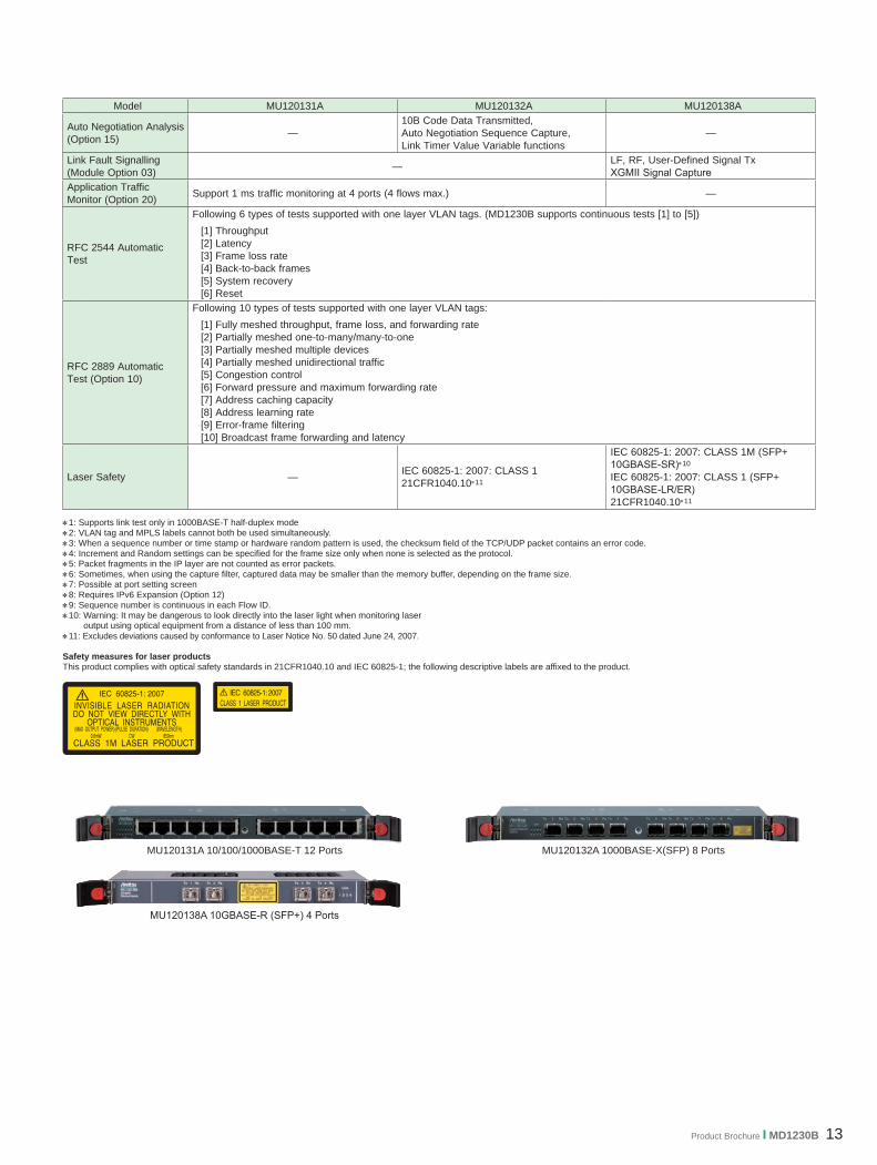
MU120131A 10/100/1000BASE-T 12 Ports MU120132A 1000BASE-X(SFP) 8 Ports
Model MU120131A MU120132A MU120138A
Auto Negotiation Analysis (Option 15) —
10B Code Data Transmitted, Auto Negotiation Sequence Capture, Link Timer Value Variable functions
—
Link Fault Signalling (Module Option 03) — LF, RF, User-Defined Signal Tx
XGMII Signal CaptureApplication Traffic Monitor (Option 20) Support 1 ms traffic monitoring at 4 ports (4 flows max.) —
RFC 2544 Automatic Test
Following 6 types of tests supported with one layer VLAN tags. (MD1230B supports continuous tests [1] to [5]) [1] Throughput[2] Latency[3] Frame loss rate[4] Back-to-back frames[5] System recovery[6] Reset
RFC 2889 Automatic Test (Option 10)
Following 10 types of tests supported with one layer VLAN tags:[1] Fully meshed throughput, frame loss, and forwarding rate[2] Partially meshed one-to-many/many-to-one[3] Partially meshed multiple devices[4] Partially meshed unidirectional traffic[5] Congestion control[6] Forward pressure and maximum forwarding rate[7] Address caching capacity [8] Address learning rate[9] Error-frame filtering[10] Broadcast frame forwarding and latency
Laser Safety — IEC 60825-1: 2007: CLASS 121CFR1040.10*11
IEC 60825-1: 2007: CLASS 1M (SFP+ 10GBASE-SR)*10
IEC 60825-1: 2007: CLASS 1 (SFP+ 10GBASE-LR/ER) 21CFR1040.10*11
*1: Supports link test only in 1000BASE-T half-duplex mode*2: VLAN tag and MPLS labels cannot both be used simultaneously.*3: When a sequence number or time stamp or hardware random pattern is used, the checksum field of the TCP/UDP packet contains an error code.*4: Increment and Random settings can be specified for the frame size only when none is selected as the protocol.*5: Packet fragments in the IP layer are not counted as error packets.*6: Sometimes, when using the capture filter, captured data may be smaller than the memory buffer, depending on the frame size.*7: Possible at port setting screen*8: Requires IPv6 Expansion (Option 12) *9: Sequence number is continuous in each Flow ID.*10: Warning: It may be dangerous to look directly into the laser light when monitoring laser
output using optical equipment from a distance of less than 100 mm. *11: Excludes deviations caused by conformance to Laser Notice No. 50 dated June 24, 2007.
Safety measures for laser productsThis product complies with optical safety standards in 21CFR1040.10 and IEC 60825-1; the following descriptive labels are affixed to the product.
MU120138A 10GBASE-R (SFP+) 4 Ports
14 Product Brochure l MD1230B
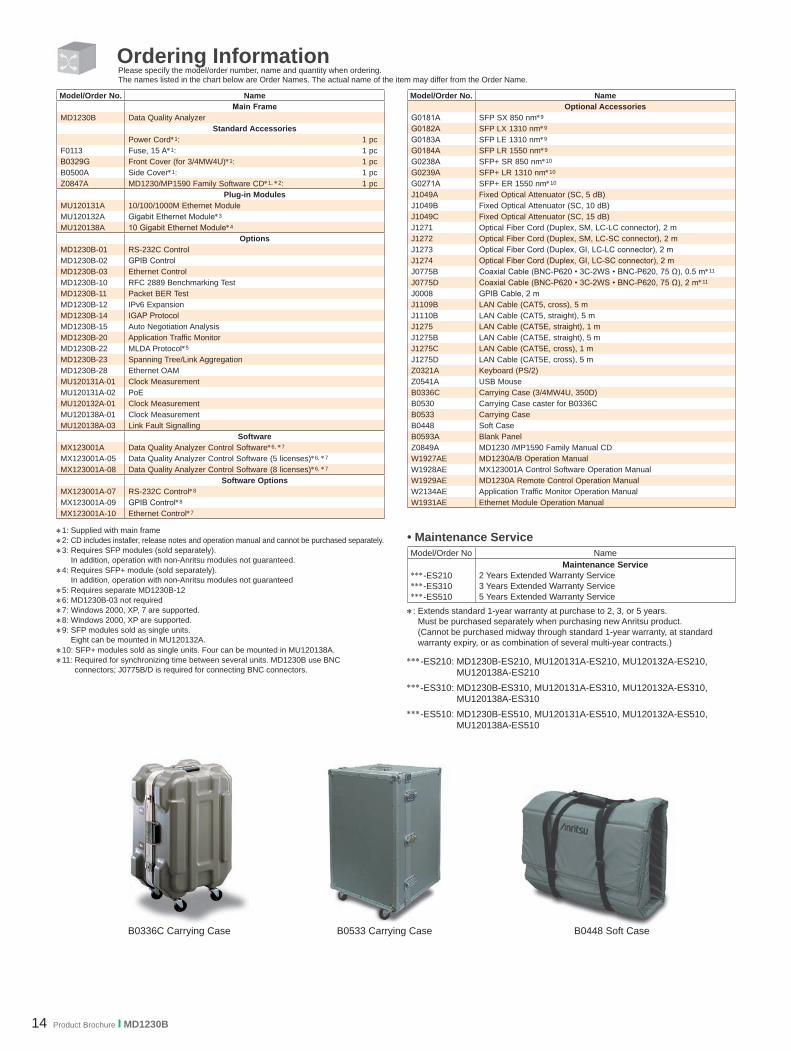
Ordering InformationPlease specify the model/order number, name and quantity when ordering.The names listed in the chart below are Order Names. The actual name of the item may differ from the Order Name.
*1: Supplied with main frame*2: CD includes installer, release notes and operation manual and cannot be purchased separately.*3: Requires SFP modules (sold separately).
In addition, operation with non-Anritsu modules not guaranteed.*4: Requires SFP+ module (sold separately).
In addition, operation with non-Anritsu modules not guaranteed *5: Requires separate MD1230B-12*6: MD1230B-03 not required*7: Windows 2000, XP, 7 are supported.*8: Windows 2000, XP are supported.*9: SFP modules sold as single units.
Eight can be mounted in MU120132A.*10: SFP+ modules sold as single units. Four can be mounted in MU120138A.*11: Required for synchronizing time between several units. MD1230B use BNC
connectors; J0775B/D is required for connecting BNC connectors.
Model/Order No. NameMain Frame
MD1230B Data Quality AnalyzerStandard Accessories
Power Cord*1: 1 pcF0113 Fuse, 15 A*1: 1 pcB0329G Front Cover (for 3/4MW4U)*1: 1 pcB0500A Side Cover*1: 1 pcZ0847A MD1230/MP1590 Family Software CD*1, *2: 1 pc
Plug-in ModulesMU120131A 10/100/1000M Ethernet ModuleMU120132A Gigabit Ethernet Module*3
MU120138A 10 Gigabit Ethernet Module*4
OptionsMD1230B-01 RS-232C ControlMD1230B-02 GPIB ControlMD1230B-03 Ethernet ControlMD1230B-10 RFC 2889 Benchmarking TestMD1230B-11 Packet BER TestMD1230B-12 IPv6 ExpansionMD1230B-14 IGAP ProtocolMD1230B-15 Auto Negotiation AnalysisMD1230B-20 Application Traffic MonitorMD1230B-22 MLDA Protocol*5
MD1230B-23 Spanning Tree/Link AggregationMD1230B-28 Ethernet OAMMU120131A-01 Clock MeasurementMU120131A-02 PoEMU120132A-01 Clock MeasurementMU120138A-01 Clock MeasurementMU120138A-03 Link Fault Signalling
SoftwareMX123001A Data Quality Analyzer Control Software*6, *7
MX123001A-05 Data Quality Analyzer Control Software (5 licenses)*6, *7
MX123001A-08 Data Quality Analyzer Control Software (8 licenses)*6, *7
Software OptionsMX123001A-07 RS-232C Control*8
MX123001A-09 GPIB Control*8
MX123001A-10 Ethernet Control*7
Model/Order No. NameOptional Accessories
G0181A SFP SX 850 nm*9
G0182A SFP LX 1310 nm*9
G0183A SFP LE 1310 nm*9
G0184A SFP LR 1550 nm*9
G0238A SFP+ SR 850 nm*10
G0239A SFP+ LR 1310 nm*10
G0271A SFP+ ER 1550 nm*10
J1049A Fixed Optical Attenuator (SC, 5 dB) J1049B Fixed Optical Attenuator (SC, 10 dB) J1049C Fixed Optical Attenuator (SC, 15 dB) J1271 Optical Fiber Cord (Duplex, SM, LC-LC connector), 2 mJ1272 Optical Fiber Cord (Duplex, SM, LC-SC connector), 2 mJ1273 Optical Fiber Cord (Duplex, GI, LC-LC connector), 2 mJ1274 Optical Fiber Cord (Duplex, GI, LC-SC connector), 2 mJ0775B Coaxial Cable (BNC-P620 • 3C-2WS • BNC-P620, 75 Ω), 0.5 m*11
J0775D Coaxial Cable (BNC-P620 • 3C-2WS • BNC-P620, 75 Ω), 2 m*11
J0008 GPIB Cable, 2 mJ1109B LAN Cable (CAT5, cross), 5 mJ1110B LAN Cable (CAT5, straight), 5 mJ1275 LAN Cable (CAT5E, straight), 1 mJ1275B LAN Cable (CAT5E, straight), 5 mJ1275C LAN Cable (CAT5E, cross), 1 mJ1275D LAN Cable (CAT5E, cross), 5 mZ0321A Keyboard (PS/2) Z0541A USB MouseB0336C Carrying Case (3/4MW4U, 350D) B0530 Carrying Case caster for B0336CB0533 Carrying CaseB0448 Soft CaseB0593A Blank PanelZ0849A MD1230 /MP1590 Family Manual CDW1927AE MD1230A/B Operation ManualW1928AE MX123001A Control Software Operation ManualW1929AE MD1230A Remote Control Operation ManualW2134AE Application Traffic Monitor Operation ManualW1931AE Ethernet Module Operation Manual
• Maintenance ServiceModel/Order No Name
***-ES210***-ES310***-ES510
Maintenance Service2 Years Extended Warranty Service3 Years Extended Warranty Service5 Years Extended Warranty Service
*: Extends standard 1-year warranty at purchase to 2, 3, or 5 years. Must be purchased separately when purchasing new Anritsu product. (Cannot be purchased midway through standard 1-year warranty, at standard warranty expiry, or as combination of several multi-year contracts.)
***-ES210: MD1230B-ES210, MU120131A-ES210, MU120132A-ES210, MU120138A-ES210
***-ES310: MD1230B-ES310, MU120131A-ES310, MU120132A-ES310, MU120138A-ES310
***-ES510: MD1230B-ES510, MU120131A-ES510, MU120132A-ES510, MU120138A-ES510
B0336C Carrying Case B0448 Soft CaseB0533 Carrying Case

Product Brochure l MD1230B 15
Note:
Catalog No. MD1230B-E-A-1-(10.00) Printed in Japan 24/MAR/2016 ddcm/CDT