Embed Size (px)
Citation preview

Data Sheet DS/267CS/269CS-MOD
Model 267CS MModel 269CS Mwith MODBUS p
Selectable maximum working pre— Up to 41 MPa, 5945 psi
Base accuracy— ± 0.075 %/± 0.04 %
Corrected mass flow measuremensteam and fluids— Dynamic correction of pressure and
changes
One transmitter replaces three se— Saving initial purchase costs
2600T Series PresEngineered solutioapplications
BUS-EN Rev. 01
ultivariableultivariablerotocol for mass flow
ssure
t for gases,
temperature
parate transmitters
Reduced process penetrations— Saves money and reduces the chance of leaks
Fewer transmitters, less wiring and fewer shut-off valves— Reduce installation costs
Greater reliability— Due to fewer devices and less wiring
sure Transmittersns for all
Series 2600T Pressure Transmitters DS/267CS/269CS/MODBUS-EN_01Model 267CS/269CS Multivariable
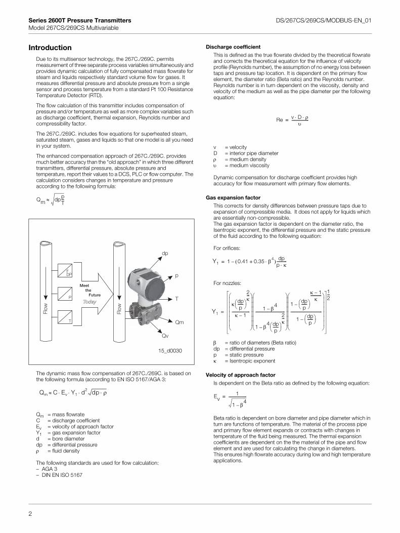
IntroductionDue to its multisensor technology, the 267C./269C. permits measurement of three separate process variables simultaneously and provides dynamic calculation of fully compensated mass flowrate for steam and liquids respectively standard volume flow for gases. It measures differential pressure and absolute pressure from a single sensor and process temperature from a standard Pt 100 Resistance Temperature Detector (RTD).
The flow calculation of this transmitter includes compensation of pressure and/or temperature as well as more complex variables such as discharge coefficient, thermal expansion, Reynolds number and compressibility factor.
The 267C./269C. includes flow equations for superheated steam, saturated steam, gases and liquids so that one model is all you need in your system.
The enhanced compensation approach of 267C./269C. provides much better accuracy than the “old approach” in which three different transmitters, differential pressure, absolute pressure and temperature, report their values to a DCS, PLC or flow computer. The calculation considers changes in temperature and pressure according to the following formula:
The dynamic mass flow compensation of 267C./269C. is based on the following formula (according to EN ISO 5167/AGA 3:
Qm = mass flowrate C = discharge coefficientEv = velocity of approach factorY1 = gas expansion factord = bore diameterdp = differential pressureρ = fluid density
Discharge coefficient
This is defined as the true flowrate divided by the theoretical flowrate and corrects the theoretical equation for the influence of velocity profile (Reynolds number), the assumption of no energy loss between taps and pressure tap location. It is dependent on the primary flow element, the diameter ratio (Beta ratio) and the Reynolds number. Reynolds number is in turn dependent on the viscosity, density and velocity of the medium as well as the pipe diameter per the following equation:
v = velocityD = interior pipe diameterρ = medium densityυ = medium viscosity
Dynamic compensation for discharge coefficient provides high accuracy for flow measurement with primary flow elements.
Gas expansion factor
This corrects for density differences between pressure taps due to expansion of compressible media. It does not apply for liquids which are essentially non-compressible.The gas expansion factor is dependent on the diameter ratio, the Isentropic exponent, the differential pressure and the static pressure of the fluid according to the following equation:
For orifices:
For nozzles:
β = ratio of diameters (Beta ratio)dp = differential pressurep = static pressure κ = Isentropic exponent
Velocity of approach factor
Is dependent on the Beta ratio as defined by the following equation:
Beta ratio is dependent on bore diameter and pipe diameter which in turn are functions of temperature. The material of the process pipe and primary flow element expands or contracts with changes in temperature of the fluid being measured. The thermal expansion coefficients are dependent on the the material of the pipe and flow element and are used for calculating the change in diameters.
Qm dppT---≈
15_d0030
Flow
Flow
FDP
P
T
dp
p
T
Qm
Qv
Meetthe
Future
Qm C Ev Y1 d2 dp ρ⋅⋅ ⋅ ⋅≈
Re v D ρ⋅ ⋅υ
-------------------=
Y1 1 0.41 0.35 β4⋅+( ) dpp κ⋅-----------–=
Y1
κ dpp
------⎝ ⎠⎛ ⎞
2κ---
κ 1–--------------------
⎝ ⎠⎜ ⎟⎜ ⎟⎜ ⎟⎜ ⎟⎜ ⎟⎜ ⎟⎛ ⎞
1 β4
–
1 β4 dp
p------⎝ ⎠
⎛ ⎞
2κ---
–
---------------------------------
⎝ ⎠⎜ ⎟⎜ ⎟⎜ ⎟⎜ ⎟⎜ ⎟⎜ ⎟⎛ ⎞
1 dpp
------⎝ ⎠⎛ ⎞
κ 1–κ
------------
–
1 dpp
------⎝ ⎠⎛ ⎞–
-----------------------------------
⎝ ⎠⎜ ⎟⎜ ⎟⎜ ⎟⎜ ⎟⎜ ⎟⎜ ⎟⎛ ⎞
12---
=
Ev1
1 β4
–
--------------------=
2
The following standards are used for flow calculation:– AGA 3– DIN EN ISO 5167
This ensures high flowrate accuracy during low and high temperature applications.
Series 2600T Pressure Transmitters DS/267CS/269CS/MODBUS-EN_01Model 267CS/269CS Multivariable
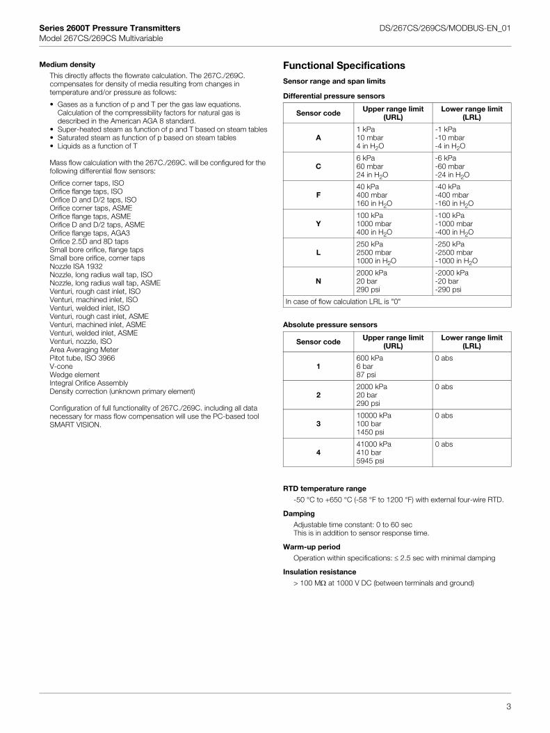
Medium density
This directly affects the flowrate calculation. The 267C./269C. compensates for density of media resulting from changes in temperature and/or pressure as follows:
• Gases as a function of p and T per the gas law equations. Calculation of the compressibility factors for natural gas is described in the American AGA 8 standard.
• Super-heated steam as function of p and T based on steam tables• Saturated steam as function of p based on steam tables• Liquids as a function of T
Mass flow calculation with the 267C./269C. will be configured for the following differential flow sensors:
Orifice corner taps, ISOOrifice flange taps, ISOOrifice D and D/2 taps, ISOOrifice corner taps, ASMEOrifice flange taps, ASMEOrifice D and D/2 taps, ASMEOrifice flange taps, AGA3Orifice 2.5D and 8D tapsSmall bore orifice, flange tapsSmall bore orifice, corner tapsNozzle ISA 1932Nozzle, long radius wall tap, ISONozzle, long radius wall tap, ASMEVenturi, rough cast inlet, ISOVenturi, machined inlet, ISOVenturi, welded inlet, ISOVenturi, rough cast inlet, ASMEVenturi, machined inlet, ASMEVenturi, welded inlet, ASMEVenturi, nozzle, ISOArea Averaging MeterPitot tube, ISO 3966V-coneWedge elementIntegral Orifice AssemblyDensity correction (unknown primary element)
Configuration of full functionality of 267C./269C. including all data necessary for mass flow compensation will use the PC-based tool SMART VISION.
Functional SpecificationsSensor range and span limits
Differential pressure sensors
Absolute pressure sensors
RTD temperature range
-50 °C to +650 °C (-58 °F to 1200 °F) with external four-wire RTD.
Damping
Adjustable time constant: 0 to 60 secThis is in addition to sensor response time.
Warm-up period
Operation within specifications: ≤ 2.5 sec with minimal damping
Insulation resistance
> 100 MΩ at 1000 V DC (between terminals and ground)
Sensor code Upper range limit (URL)
Lower range limit (LRL)
A1 kPa10 mbar4 in H2O
-1 kPa-10 mbar-4 in H2O
C6 kPa60 mbar24 in H2O
-6 kPa-60 mbar-24 in H2O
F40 kPa400 mbar160 in H2O
-40 kPa-400 mbar-160 in H2O
Y100 kPa1000 mbar400 in H2O
-100 kPa-1000 mbar-400 in H2O
L250 kPa2500 mbar1000 in H2O
-250 kPa-2500 mbar-1000 in H2O
N2000 kPa20 bar290 psi
-2000 kPa-20 bar-290 psi
In case of flow calculation LRL is "0"
Sensor code Upper range limit (URL)
Lower range limit (LRL)
1600 kPa6 bar87 psi
0 abs
22000 kPa20 bar290 psi
0 abs
310000 kPa100 bar1450 psi
0 abs
441000 kPa410 bar5945 psi
0 abs
3
Series 2600T Pressure Transmitters DS/267CS/269CS/MODBUS-EN_01Model 267CS/269CS Multivariable
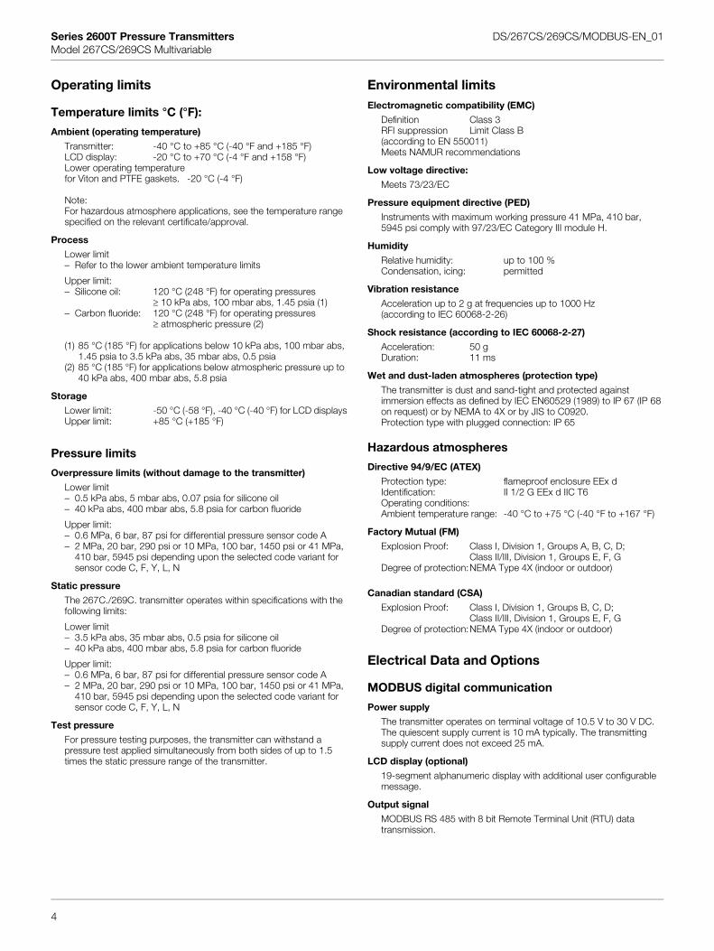
Operating limits
Temperature limits °C (°F):
Ambient (operating temperature)
Transmitter: -40 °C to +85 °C (-40 °F and +185 °F)LCD display: -20 °C to +70 °C (-4 °F and +158 °F)Lower operating temperature for Viton and PTFE gaskets. -20 °C (-4 °F)
Note:For hazardous atmosphere applications, see the temperature range specified on the relevant certificate/approval.
Process
Lower limit– Refer to the lower ambient temperature limits
Upper limit:– Silicone oil: 120 °C (248 °F) for operating pressures
≥ 10 kPa abs, 100 mbar abs, 1.45 psia (1)– Carbon fluoride: 120 °C (248 °F) for operating pressures
≥ atmospheric pressure (2)
(1) 85 °C (185 °F) for applications below 10 kPa abs, 100 mbar abs, 1.45 psia to 3.5 kPa abs, 35 mbar abs, 0.5 psia
(2) 85 °C (185 °F) for applications below atmospheric pressure up to 40 kPa abs, 400 mbar abs, 5.8 psia
Storage
Lower limit: -50 °C (-58 °F), -40 °C (-40 °F) for LCD displaysUpper limit: +85 °C (+185 °F)
Pressure limits
Overpressure limits (without damage to the transmitter)
Lower limit– 0.5 kPa abs, 5 mbar abs, 0.07 psia for silicone oil– 40 kPa abs, 400 mbar abs, 5.8 psia for carbon fluoride
Upper limit:– 0.6 MPa, 6 bar, 87 psi for differential pressure sensor code A– 2 MPa, 20 bar, 290 psi or 10 MPa, 100 bar, 1450 psi or 41 MPa,
410 bar, 5945 psi depending upon the selected code variant for sensor code C, F, Y, L, N
Static pressure
The 267C./269C. transmitter operates within specifications with the following limits:
Lower limit– 3.5 kPa abs, 35 mbar abs, 0.5 psia for silicone oil– 40 kPa abs, 400 mbar abs, 5.8 psia for carbon fluoride
Upper limit:– 0.6 MPa, 6 bar, 87 psi for differential pressure sensor code A– 2 MPa, 20 bar, 290 psi or 10 MPa, 100 bar, 1450 psi or 41 MPa,
410 bar, 5945 psi depending upon the selected code variant for sensor code C, F, Y, L, N
Test pressure
For pressure testing purposes, the transmitter can withstand a pressure test applied simultaneously from both sides of up to 1.5 times the static pressure range of the transmitter.
Environmental limitsElectromagnetic compatibility (EMC)
Definition Class 3RFI suppression Limit Class B(according to EN 550011)Meets NAMUR recommendations
Low voltage directive:
Meets 73/23/EC
Pressure equipment directive (PED)
Instruments with maximum working pressure 41 MPa, 410 bar, 5945 psi comply with 97/23/EC Category III module H.
Humidity
Relative humidity: up to 100 %Condensation, icing: permitted
Vibration resistance
Acceleration up to 2 g at frequencies up to 1000 Hz (according to IEC 60068-2-26)
Shock resistance (according to IEC 60068-2-27)
Acceleration: 50 gDuration: 11 ms
Wet and dust-laden atmospheres (protection type)
The transmitter is dust and sand-tight and protected against immersion effects as defined by IEC EN60529 (1989) to IP 67 (IP 68 on request) or by NEMA to 4X or by JIS to C0920.Protection type with plugged connection: IP 65
Hazardous atmospheres
Directive 94/9/EC (ATEX)
Protection type: flameproof enclosure EEx dIdentification: II 1/2 G EEx d IIC T6Operating conditions:Ambient temperature range: -40 °C to +75 °C (-40 °F to +167 °F)
Factory Mutual (FM)
Explosion Proof: Class I, Division 1, Groups A, B, C, D;Class II/III, Division 1, Groups E, F, G
Degree of protection:NEMA Type 4X (indoor or outdoor)
Canadian standard (CSA)
Explosion Proof: Class I, Division 1, Groups B, C, D;Class II/III, Division 1, Groups E, F, G
Degree of protection:NEMA Type 4X (indoor or outdoor)
Electrical Data and Options
MODBUS digital communication
Power supply
The transmitter operates on terminal voltage of 10.5 V to 30 V DC.The quiescent supply current is 10 mA typically. The transmitting supply current does not exceed 25 mA.
LCD display (optional)
19-segment alphanumeric display with additional user configurable message.
Output signal
4
MODBUS RS 485 with 8 bit Remote Terminal Unit (RTU) data transmission.
Series 2600T Pressure Transmitters DS/267CS/269CS/MODBUS-EN_01Model 267CS/269CS Multivariable
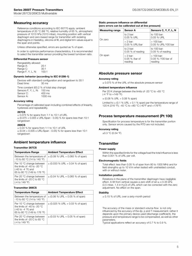
Measuring accuracyReference conditions according to IEC 60770 apply: ambienttemperature of 20 °C (68 °F), relative humidity of 65 %, atmospheric pressure of 1013 hPa (1013 mbar), mounting position with vertical diaphragm and zero-based range for transmitter with isolating diaphragms in Hastelloy, silicone oil fill, and digital trim values equal to the span end points.
Unless otherwise specified, errors are quoted as % of span.
In order to optimize performance characteristics, it is recommended to select the transmitter sensor providing the lowest turndown ratio.
Differential Pressure sensor
Rangeability allowed:Range A: 20:1Range C: 30:1Range F, Y, L, N: 100:1
Dynamic behavior (according to IEC 61298-1)
Devices with standard configuration and rangedown to 30:1Dead time: 30 ms
Time constant (63.2 % of total step change)Sensors F, Y, L, N: 150 msSensor C: 400 msSensor A: 1000 ms
Accuracy rating
Percentage of calibrated span including combined effects of linearity, hysteresis and repeatability.
267CS± 0.075 % for spans from 1:1 to 10:1 of URL± (0.075 + 0.005 x URL/Span - 0.05) % for spans less than 10:1 rangedown
269CS± 0.04 % for spans from 1:1 to 10:1 of URL± (0.04 + 0.005 x URL/Span - 0.05) % for spans less than 10:1 rangedown
Ambient temperature influenceTransmitter 267CS
Transmitter 269CS
Static pressure influence on differential(zero errors can be calibrated out at line pressure)
Absolute pressure sensorAccuracy rating
± 0.075 % of the URL of the absolute pressure sensor
Ambient temperature influence
Per 20 K change between the limits of -20 °C to +65 °C (-4 °F to +149 °F):
± (0.08 % URL + 0.08 % span)
Limited to ± (0.1 % URL + 0.1 % span) per the temperature range of 120 K (216 °F); -40 °C to +80 °C (-40°F and +176°F)
Process temperature measurement (Pt 100)Specification for process temperature is for the transmitter portion only. Sensor errors caused by the RTD are not included.
Accuracy rating
±0.3 °C (0.54 °F)
TransmitterPower supply
Within the specified limits for the voltage/load the total influence is less than 0.001 % of URL per volt.
Electromagnetic fields
Total effect: less than 0.05 % of span from 80 to 1000 MHz and for field strengths up to 10 V/m when tested with unshielded conduit, with or without meter.
Installation position
Rotations in the plane of the transmitter diaphragm have negligible effect. A tilt from vertical causes a zero shift of sin α x 0.35 kPa (3.5 mbar, 1.4 in H2O) of URL which can be corrected with the zero adjustment. No effect on the span.
Stability
± 0.15 % of URL over a sixty-month period
The accuracy of the mass or standard volume flow is not only influenced by the accuracy of the dp, p and T measurement; rather it depends upon the primary device used (discharge coefficient), the pressure and temperature range to be compensated, as well as other
Temperature Range Ambient Temperature Effect
Between the temperature of-10 to 60 °C (14 to 140 °F)
± (0.08 % URL + 0.065 % of span)
Per 10 °C change between the limits of -40 to -20 °C (-40 to -4 °F) and65 to 80 °C (149 to 176 °F)
± (0.033 % URL + 0.04 % of span)
Per 20 °C change between the limits of -20 C to 65 °C (-4 to 149 °F)
± (0.04 % URL + 0.065 % of span)
Temperature Range Ambient Temperature Effect
Between the temperature of-10 to 60 °C (14 to 140 °F)
± (0.06 % URL + 0.05 % of span)
Per 10 °C change between the limits of -40 to -20 °C (-40 to -4 °F) and65 to 80 °C (149 to 176 °F)
± (0.025 % URL + 0.03 % of span)
Per 20 °C change between ± (0.03 % URL + 0.05 % of span)
Measuring range Sensor A Sensors C, Y, F, L, N
On zero
to 2 bar:0.05 % URL
to 100 bar:0.05 % URL
> 2 bar:0.05 % URL/bar
> 100 bar:0.05 % URL/100 bar
On span
to 2 bar:0.05 % of reading
to 100 bar:0.05 % of reading
> 2 bar:0.05 % /bar of reading
> 100 bar:0.05 % /100 bar ofreading
5
parameters.Typical applications reflect an accuracy of 0.7 % to 0.9 %.
the limits of -20 C to 65 °C (-4 to 149 °F)
Series 2600T Pressure Transmitters DS/267CS/269CS/MODBUS-EN_01Model 267CS/269CS Multivariable
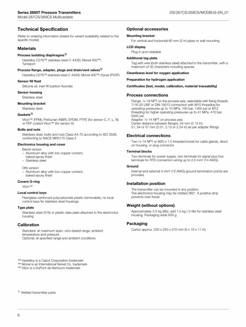
Technical Specification(Refer to ordering information sheets for variant availability related to the specific model)
Materials
Process isolating diaphragms1)
Hastelloy C276™ stainless steel (1.4435); Monel 400™,Tantalum
Process flange, adapter, plugs and drain/vent valves1)
Hastelloy C276™ stainless steel (1.4404); Monel 400™; Kynar (PVDF)
Sensor fill fluid
Silicone oil, inert fill (carbon fluoride)
Sensor housing
Stainless steel
Mounting bracket
Stainless steel
Gaskets1)
Viton™ (FPM), Perbunan (NBR), EPDM, PTFE (for sensor C, F, L, N) or FEP coated Viton™ (for sensor A)
Bolts and nuts
Stainless steel, bolts and nuts Class A4-70 according to ISO 3506, conforming to NACE MR0175 Class II
Electronics housing and cover
Barrel version– Aluminum alloy with low copper content,
baked epoxy finish– Stainless steel
DIN version– Aluminum alloy with low copper content,
baked epoxy finish
Covers O-ring
Viton™
Local control keys
Fiberglass-reinforced polycarbonate plastic (removable), no local control keys for stainless steel housings.
Type plate
Stainless steel (316) or plastic data plate attached to the electronics housing
CalibrationStandard: at maximum span, zero-based range, ambient temperature and pressureOptional: at specified range and ambient conditions
™ Hastelloy is a Cabot Corporation trademark™ Monel is an International Nickel Co. trademark™ Viton is a DuPont de Nemours trademark
Optional accessories
Mounting bracket
For vertical and horizontal 60 mm (2 in) pipes or wall mounting
LCD display
Plug-in and rotatable
Additional tag plate
Tag with wire (both stainless steel) attached to the transmitter, with a maximum of 30 characters including spaces.
Cleanliness level for oxygen application
Preparation for hydrogen application
Certificates (test, model, calibration, material traceability)
Process connectionsFlange: ¼-18 NPT on the process axis, selectable with fixing threads 7/16-20 UNF or DIN 19213 connection with M10 threading for operating pressures up to 10 MPa, 100 bar, 1450 psi or M12 threading for higher operating pressures up to 41 MPa, 410 bar, 5945 psiAdapter: ½-14 NPT on process axisCenter distance between flanges: 54 mm (2.13 in);51, 54 or 57 mm (2.01, 2.13 or 2.24 in) as per adapter fittings
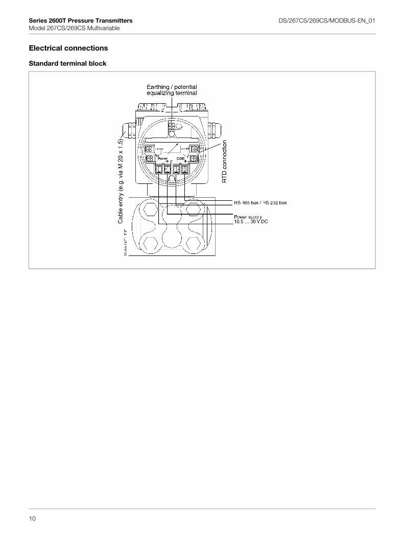
Electrical connectionsTwo ½-14 NPT or M20 x 1.5 threaded bores for cable glands, direct on housing, or plug connector
Terminal blocks
Two terminals for power supply, two terminals for signal plus four terminals for RTD connection wiring up to 2.5 mm² (14 AWG).
Ground
Internal and external 4 mm² (12 AWG) ground termination points are provided.
Installation positionThe transmitter can be mounted in any position. The electronics housing may be rotated 360°. A positive stop prevents over-travel.
Weight (without options)Approximately 3.5 kg (8lb), add 1.5 kg ( 3.4lb) for stainless steel housing. Packaging adds 650 g
PackagingCarton approx. 230 x 250 x 270 mm (9 x 10 x 11 in)
6
1) Wetted transmitter parts
Series 2600T Pressure Transmitters DS/267CS/269CS/MODBUS-EN_01Model 267CS/269CS Multivariable
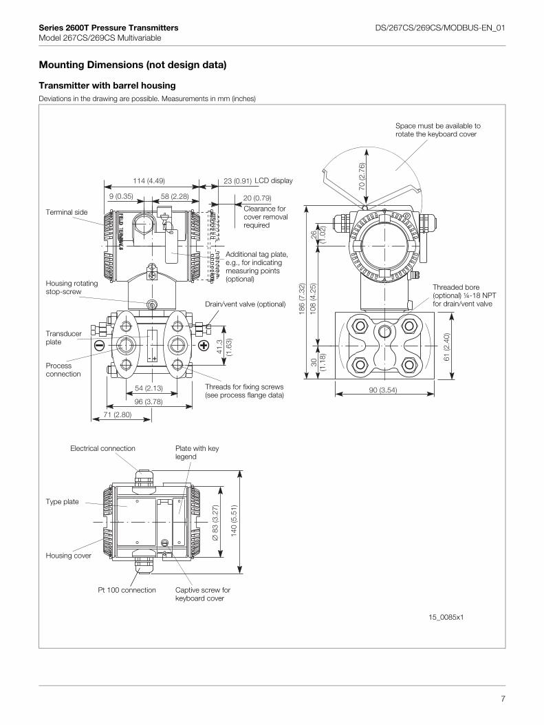
Mounting Dimensions (not design data)
Transmitter with barrel housingDeviations in the drawing are possible. Measurements in mm (inches)
140
(5.5
1)
∅83
(3.2
7)
54 (2.13)
96 (3.78)
41.3
(1.6
3)
9 (0.35) 58 (2.28)
114 (4.49) 23 (0.91)
20 (0.79)
71 (2.80)
70 (2
.76)
26(1
.02)
186
(7.3
2)
108
(4.2
5)30
(1.1
8)
90 (3.54)
61 (2
.40)
+-
Terminal side
Space must be available to rotate the keyboard cover
Threaded bore (optional) ¼-18 NPTfor drain/vent valve
Additional tag plate, e.g., for indicating measuring points (optional)
LCD display
Clearance for cover removal required
Housing rotatingstop-screw
Transducer plate
Process connection
Threads for fixing screws (see process flange data)
Electrical connection
Type plate
Housing cover
Captive screw for keyboard cover
Plate with key legend
Pt 100 connection
Drain/vent valve (optional)
7
15_0085x1
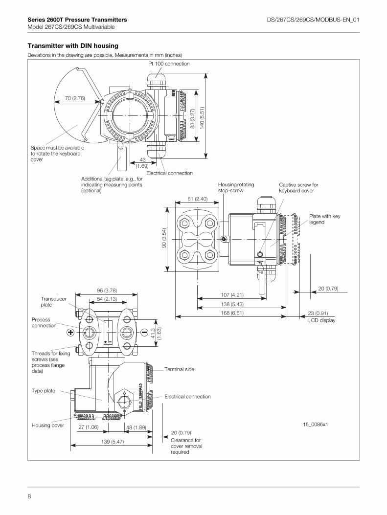
Series 2600T Pressure Transmitters DS/267CS/269CS/MODBUS-EN_01Model 267CS/269CS Multivariable
Transmitter with DIN housingDeviations in the drawing are possible. Measurements in mm (inches)
43(1.69)
140
(5.5
1)
70 (2.76)
83 (3
.27)
61 (2.40)
107 (4.21)
138 (5.43)
168 (6.61)
20 (0.79)
23 (0.91)
90 (3
.54)
54 (2.13)
96 (3.78)
41.3
(1.6
3)
48 (1.89)27 (1.06)20 (0.79)
Terminal side
Space must be available to rotate the keyboard cover
Additional tag plate, e.g., for indicating measuring points (optional)
Housing rotating stop-screw
Transducer plate
Process connection
Threads for fixing screws (see process flange data)
Electrical connectionType plate
Housing cover
Captive screw for keyboard cover
Plate with key legend
Electrical connection
LCD display
15_0086x1
Pt 100 connection
8
139 (5.47) Clearance for cover removal required
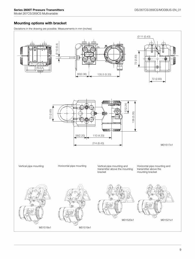
Series 2600T Pressure Transmitters DS/267CS/269CS/MODBUS-EN_01Model 267CS/269CS Multivariable
Mounting options with bracketDeviations in the drawing are possible. Measurements in mm (inches)
∅10
(0.4
)
60(2.36) 135.5 (5.33)
72 (2.83)
72 (2
.83)
∅ 11 (0.43)
214 (8.43)
56(2.20)
72 (2
.83)
136
(5.3
5)57(2
.24)
110 (4.33)
Vertical pipe mounting Horizontal pipe mounting Vertical pipe mounting and transmitter above the mounting bracket
Horizontal pipe mounting and transmitter above the mounting bracket
M01517x1
9
M01521x1M01520x1
M01519x1M01518x1
Series 2600T Pressure Transmitters DS/267CS/269CS/MODBUS-EN_01Model 267CS/269CS Multivariable
Electrical connections
Standard terminal block
10
Series 2600T Pressure Transmitters DS/267CS/269CS/MODBUS-EN_01Model 267CS/269CS Multivariable
Ordering information
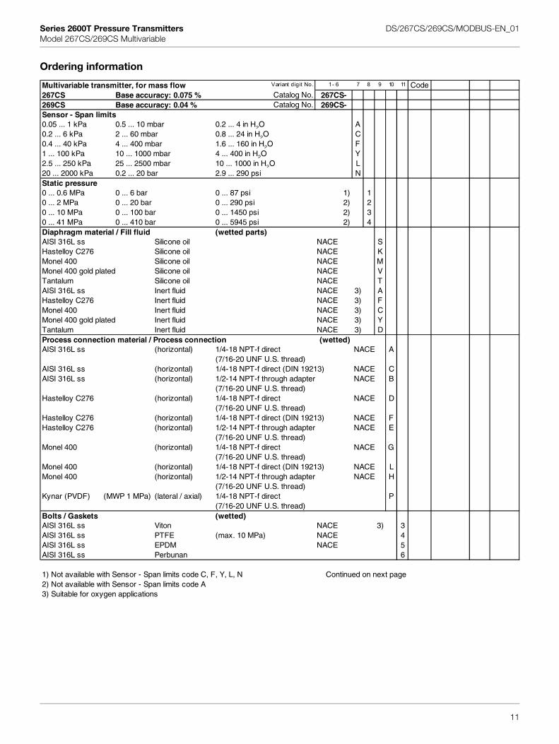
Multivariable transmitter, for mass flow Variant digit No. 1 - 6 7 8 9 10 11 Code267CS Base accuracy: 0.075 % Catalog No. 267CS-269CS Base accuracy: 0.04 % Catalog No. 269CS-Sensor - Span limits0.05 ... 1 kPa 0.5 ... 10 mbar 0.2 ... 4 in H2O A0.2 ... 6 kPa 2 ... 60 mbar 0.8 ... 24 in H2O C0.4 ... 40 kPa 4 ... 400 mbar 1.6 ... 160 in H2O F1 ... 100 kPa 10 ... 1000 mbar 4 ... 400 in H2O Y2.5 ... 250 kPa 25 ... 2500 mbar 10 ... 1000 in H2O L20 ... 2000 kPa 0.2 ... 20 bar 2.9 ... 290 psi NStatic pressure0 ... 0.6 MPa 0 ... 6 bar 0 ... 87 psi 1) 10 ... 2 MPa 0 ... 20 bar 0 ... 290 psi 2) 20 ... 10 MPa 0 ... 100 bar 0 ... 1450 psi 2) 30 ... 41 MPa 0 ... 410 bar 0 ... 5945 psi 2) 4Diaphragm material / Fill fluid (wetted parts)AISI 316L ss Silicone oil NACE SHastelloy C276 Silicone oil NACE KMonel 400 Silicone oil NACE MMonel 400 gold plated Silicone oil NACE VTantalum Silicone oil NACE TAISI 316L ss Inert fluid NACE 3) AHastelloy C276 Inert fluid NACE 3) FMonel 400 Inert fluid NACE 3) CMonel 400 gold plated Inert fluid NACE 3) YTantalum Inert fluid NACE 3) DProcess connection material / Process connection (wetted)AISI 316L ss (horizontal) 1/4-18 NPT-f direct NACE A
(7/16-20 UNF U.S. thread)AISI 316L ss (horizontal) 1/4-18 NPT-f direct (DIN 19213) NACE CAISI 316L ss (horizontal) 1/2-14 NPT-f through adapter NACE B
(7/16-20 UNF U.S. thread)Hastelloy C276 (horizontal) 1/4-18 NPT-f direct NACE D
(7/16-20 UNF U.S. thread)Hastelloy C276 (horizontal) 1/4-18 NPT-f direct (DIN 19213) NACE FHastelloy C276 (horizontal) 1/2-14 NPT-f through adapter NACE E
(7/16-20 UNF U.S. thread)Monel 400 (horizontal) 1/4-18 NPT-f direct NACE G
(7/16-20 UNF U.S. thread)Monel 400 (horizontal) 1/4-18 NPT-f direct (DIN 19213) NACE LMonel 400 (horizontal) 1/2-14 NPT-f through adapter NACE H
(7/16-20 UNF U.S. thread)Kynar (PVDF) (MWP 1 MPa) (lateral / axial) 1/4-18 NPT-f direct P
(7/16-20 UNF U.S. thread)Bolts / Gaskets (wetted)AISI 316L ss Viton NACE 3) 3AISI 316L ss PTFE (max. 10 MPa) NACE 4AISI 316L ss EPDM NACE 5AISI 316L ss Perbunan 6
1) Not available with Sensor - Span limits code C, F, Y, L, N Continued on next page2) Not available with Sensor - Span limits code A3) Suitable for oxygen applications
11
Series 2600T Pressure Transmitters DS/267CS/269CS/MODBUS-EN_01Model 267CS/269CS Multivariable
Ordering Information, continued
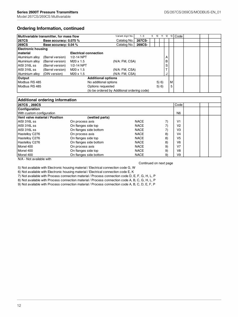
Multivariable transmitter, for mass flow Variant digit No. 1 - 6 9 10 11 12 13 Code267CS Base accuracy: 0.075 % Catalog No. 267CS-269CS Base accuracy: 0.04 % Catalog No. 269CS-Electronic housingmaterial Electrical connectionAluminium alloy (Barrel version) 1/2-14 NPT AAluminium alloy (Barrel version) M20 x 1.5 (N/A: FM, CSA) BAISI 316L ss (Barrel version) 1/2-14 NPT SAISI 316L ss (Barrel version) M20 x 1.5 (N/A: FM, CSA) TAluminium alloy (DIN version) M20 x 1.5 (N/A: FM, CSA) JOutput Additional optionsModbus RS 485 No additional options 5) 6) MModbus RS 485 Options requested 5) 6) 5
(to be ordered by Additional ordering code)
Additional ordering information267CS , 269CS CodeConfigurationWith custom configuration N6Vent valve material / Position (wetted parts)AISI 316L ss On process axis NACE 7) V1AISI 316L ss On flanges side top NACE 7) V2AISI 316L ss On flanges side bottom NACE 7) V3Hastelloy C276 On process axis NACE 8) V4Hastelloy C276 On flanges side top NACE 8) V5Hastelloy C276 On flanges side bottom NACE 8) V6Monel 400 On process axis NACE 9) V7Monel 400 On flanges side top NACE 9) V8Monel 400 On flanges side bottom NACE 9) V9N/A - Not available with
Continued on next page5) Not available with Electronic housing material / Electrical connection code G, W6) Not available with Electronic housing material / Electrical connection code E, K7) Not available with Process connection material / Process connection code D, E, F, G, H, L, P8) Not available with Process connection material / Process connection code A, B, C, G, H, L, P9) Not available with Process connection material / Process connection code A, B, C, D, E, F, P
12
Series 2600T Pressure Transmitters DS/267CS/269CS/MODBUS-EN_01Model 267CS/269CS Multivariable
Additional ordering information
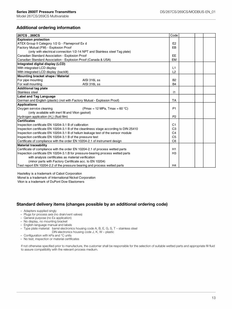
Standard delivery items (changes possible by an additional ordering code)– Adapters supplied singly– Plugs for process axis (no drain/vent valves)– General purpose (no Ex application)– No display, no mounting bracket– English-language manual and labels– Type plate material: barrel electronics housing code A, B, E, G, S, T – stainless steel
DIN electronics housing code J, K, W – plastic– Configuration with kPa and °C units– No test, inspection or material certificates
If not otherwise specified prior to manufacture, the customer shall be responsible for the selection of suitable wetted parts and appropriate fill fluid to assure compatibility with the relevant process medium.
267CS , 269CS CodeExplosion protectionATEX Group II Category 1/2 G - Flameproof Ex d E2Factory Mutual (FM) - Explosion Proof EB
(only with electrical connection 1/2-14 NPT and Stainless steel Tag plate)Canadian Standard Association - Explosion Proof EECanadian Standard Association - Explosion Proof (Canada & USA) EMIntegrated digital display (LCD)With integrated LCD display L1With integrated LCD display (backlit) L2Mounting bracket shape / MaterialFor pipe mounting AISI 316L ss B2For wall mounting AISI 316L ss B4Additional tag plateStainless steel I1Label and Tag LanguageGerman and English (plastic) (not with Factory Mutual - Explosion Proof) TAApplicationsOxygen service cleaning (Pmax = 12 MPa, Tmax = 60 °C) P1
(only available with inert fill and Viton gasket)Hydrogen application (H2) (fluid film) P2CertificatesInspection certificate EN 10204-3.1 B of calibration C1Inspection certificate EN 10204-3.1 B of the cleanliness stage according to DIN 25410 C3Inspection certificate EN 10204-3.1 B of helium leakage test of the sensor module C4Inspection certificate EN 10204-3.1 B of the pressure test C5Certificate of compliance with the order EN 10204-2.1 of instrument design C6Material traceabilityCertificate of compliance with the order EN 10204-2.1 of process wetted parts H1Inspection certificate EN 10204-3.1.B for pressure-bearing process wetted parts H3
with analysis certificates as material verification (minor parts with Factory Certificate acc. to EN 10204)
Test report EN 10204-2.2 of the pressure bearing and process wetted parts H4
Hastelloy is a trademark of Cabot CorporationMonel is a trademark of International Nickel CorporationViton is a trademark of DuPont Dow Elastomers
13
DS
/267
CS
/269
CS
_MO
DB
US
-EN
Rev
. 01
01.2
011
C
APHCUPF
AP1WUPF
APS3GPF
w
ontact us
NoteWe reserve the right to make technical changes or modify the contents of this document without prior notice. With regard to purchase orders, the agreed particulars shall prevail. ABB does not accept any responsibility whatsoever for potential errors or possible lack of information in this document.
We reserve all rights in this document and in the subject matter and illustrations contained therein. Any reproduction, disclosure to third parties or utilization of its contents – in whole or in parts – is forbidden without prior written consent of ABB.
Copyright© 2011 ABBAll rights reserved
3KXO400002R1001
BB Ltd.rocess Automationoward Road, St. Neotsambridgeshire, PE19 8EUKhone: +44 (0)1480 475321ax: +44 (0)1480 217948
BB Inc.rocess Automation25 E. County Line Roadarminster PA 18974SAhone: +1 215 674 6000ax: +1 215 674 7183
BB Automation Products GmbHrocess Automationchillerstr. 722425 Mindenermanyhone: +49 551 905-534ax: +49 551 905-555
ww.abb.com