Embed Size (px)
Citation preview
© Danfoss | 2017.05 ED.LF.Y5.02 | 1
Modulating controlled actuatorsAME 10, AME 20, AME 30AME 13, AME 23, AME 33 - with DIN EN 14597 certified safety function (spring down)
Data sheet
Description
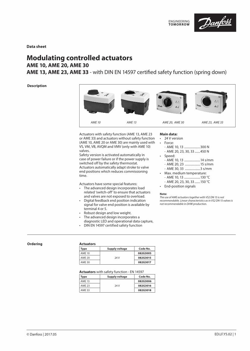
Actuators with safety function (AME 13, AME 23 or AME 33) and actuators without safety function (AME 10, AME 20 or AME 30) are mainly used with VS, VM, VB, AVQM and VMV (only with AME 10) valves. Safety version is activated automatically in case of power failure or if the power supply is switched off by the safety thermostat. Actuators automatically adapt stroke to valve end positions which reduces commissioning time.
Actuators have some special features: • The advanced design incorporates load
related ‘switch-off’ to ensure that actuators and valves are not exposed to overload.
• Digital feedback end position indication signal for valve end position is available by terminal 4 or 5.
• Robust design and low weight. • The advanced design incorporates a
diagnostic LED and operational data capture,• DIN EN 14597 certified safety function
Main data:• 24 V version• Force:
- AME 10, 13 .....................300 N- AME 20, 23, 30, 33 .......450 N
• Speed:- AME 10, 13 .....................14 s/mm- AME 20, 23 ....................15 s/mm- AME 30, 33 ....................3 s/mm
• Max. medium temperature:- AME 10, 13 .....................130 °C- AME 20, 23, 30, 33 .......150 °C
• End-position signals
Note:The use of AME actuators together with VS2 DN 15 is not recommendable. Linear characteristics as in VS2 DN 15 valves is not recommendable in DHW production.
AME 10 AME 13 AME 20, AME 30 AME 23, AME 33
Ordering ActuatorsType Supply voltage Code No.
AME 10
24 V
082G3005
AME 20 082G3015
AME 30 082G3017
Actuators with safety function - EN 14597Type Supply voltage Code No.
AME 13
24 V
082G3006
AME 23 082G3016
AME 33 082G3018
Data sheet AME 10/20/30/13/23/33
2 | © Danfoss | 2017.05 ED.LF.Y5.02
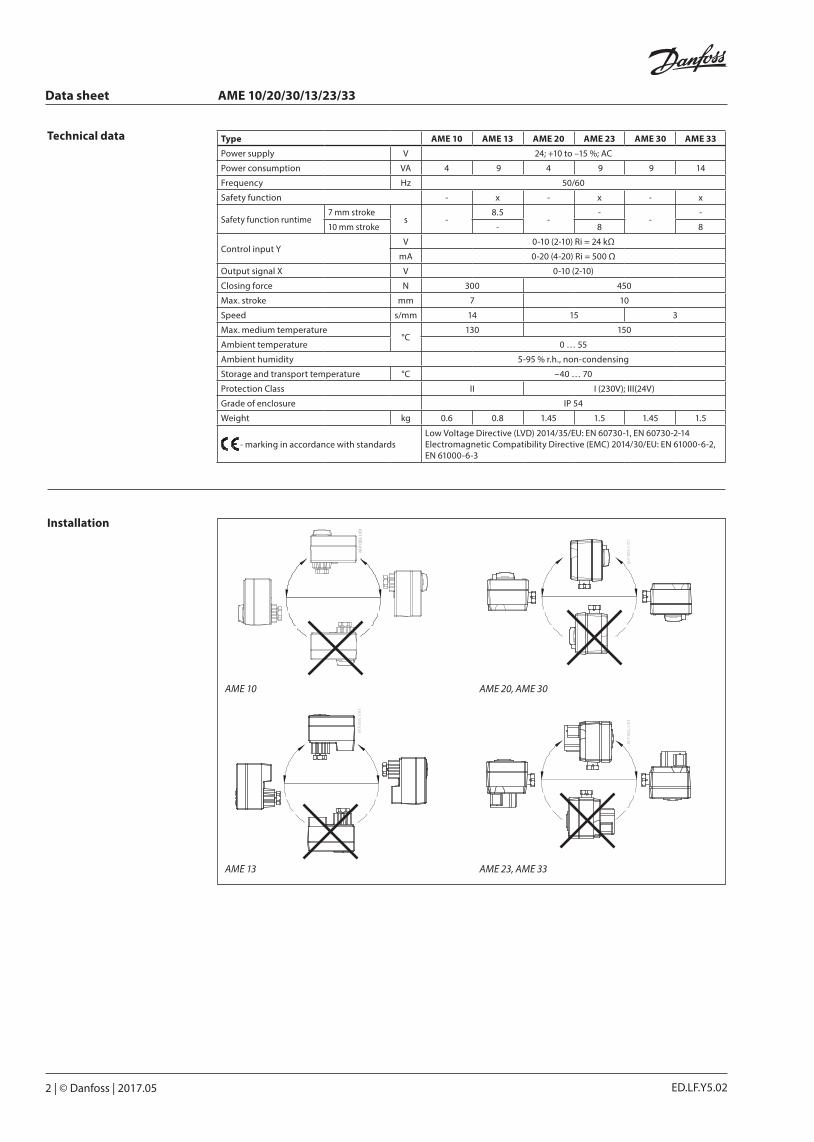
AME 13 AME 23, AME 33
AME 10 AME 20, AME 30
Installation
Technical data Type AME 10 AME 13 AME 20 AME 23 AME 30 AME 33
Power supply V 24; +10 to –15 %; AC
Power consumption VA 4 9 4 9 9 14
Frequency Hz 50/60
Safety function - x - x - x
Safety function runtime7 mm stroke
s -8.5
--
--
10 mm stroke - 8 8
Control input YV 0-10 (2-10) Ri = 24 kΩ
mA 0-20 (4-20) Ri = 500 Ω
Output signal X V 0-10 (2-10)
Closing force N 300 450
Max. stroke mm 7 10
Speed s/mm 14 15 3
Max. medium temperature°C
130 150
Ambient temperature 0 … 55
Ambient humidity 5-95 % r.h., non-condensing
Storage and transport temperature °C –40 … 70
Protection Class II I (230V); III(24V)
Grade of enclosure IP 54
Weight kg 0.6 0.8 1.45 1.5 1.45 1.5
- marking in accordance with standardsLow Voltage Directive (LVD) 2014/35/EU: EN 60730-1, EN 60730-2-14 Electromagnetic Compatibility Directive (EMC) 2014/30/EU: EN 61000-6-2, EN 61000-6-3
Data sheet AME 10/20/30/13/23/33
© Danfoss | 2017.05 | 3ED.LF.Y5.02
VS, VM, VB, AVQM
SD
VMV
SD
=
SD
or
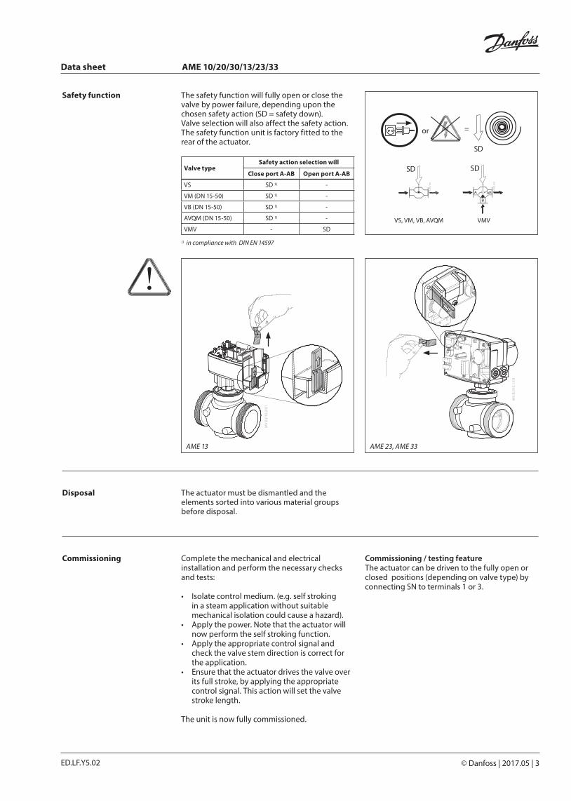
The safety function will fully open or close the valve by power failure, depending upon the chosen safety action (SD = safety down).Valve selection will also affect the safety action. The safety function unit is factory fitted to the rear of the actuator.
Valve typeSafety action selection will
Close port A-AB Open port A-AB
VS SD 1) -
VM (DN 15-50) SD 1) -
VB (DN 15-50) SD 1) -
AVQM (DN 15-50) SD 1) -
VMV - SD
1) in compliance with DIN EN 14597
Safety function
Disposal The actuator must be dismantled and the elements sorted into various material groups before disposal.
AME 13 AME 23, AME 33
Complete the mechanical and electrical installation and perform the necessary checks and tests:
• Isolate control medium. (e.g. self stroking in a steam application without suitable mechanical isolation could cause a hazard).
• Apply the power. Note that the actuator will now perform the self stroking function.
• Apply the appropriate control signal and check the valve stem direction is correct for the application.
• Ensure that the actuator drives the valve over its full stroke, by applying the appropriate control signal. This action will set the valve stroke length.
The unit is now fully commissioned.
Commissioning Commissioning / testing feature The actuator can be driven to the fully open or closed positions (depending on valve type) by connecting SN to terminals 1 or 3.
Data sheet AME 10/20/30/13/23/33
4 | © Danfoss | 2017.05 ED.LF.Y5.02
B
B
OPEN
B
B
OPEN
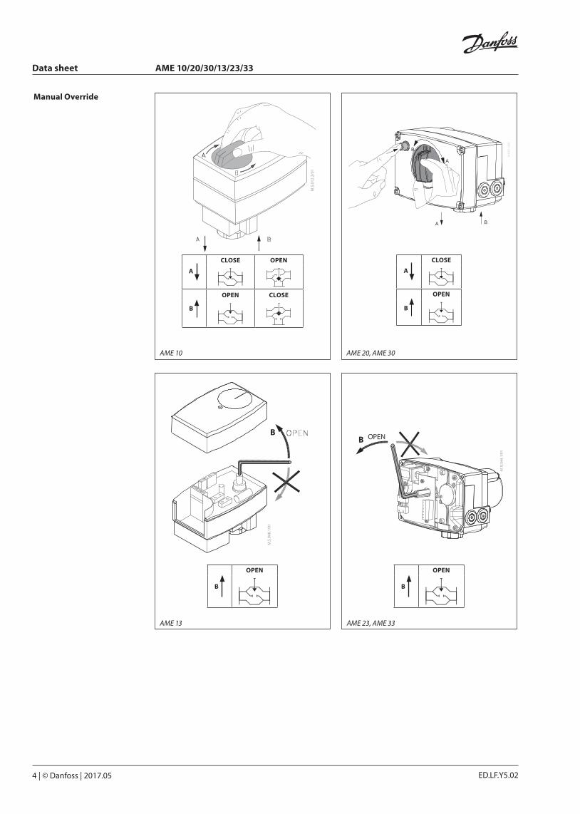
A
CLOSE
B
OPEN
A
CLOSE OPEN
B
OPEN CLOSE
Manual Override
AME 10 AME 20, AME 30
AME 23, AME 33AME 13
Data sheet AME 10/20/30/13/23/33
© Danfoss | 2017.05 | 5ED.LF.Y5.02
UI
2 V_
--- V
0 V_
--- V
Dire
ctIn
vers
e--
-Se
quen
tial
0(2)
_5(6
) V5(
6)_1
0 V
Prop
ortio
nal
3 po
int/
RLLO
G. f
low
LIN
. flo
w10
0 %
kVS
RED
. kVS
Rese
tRe
set
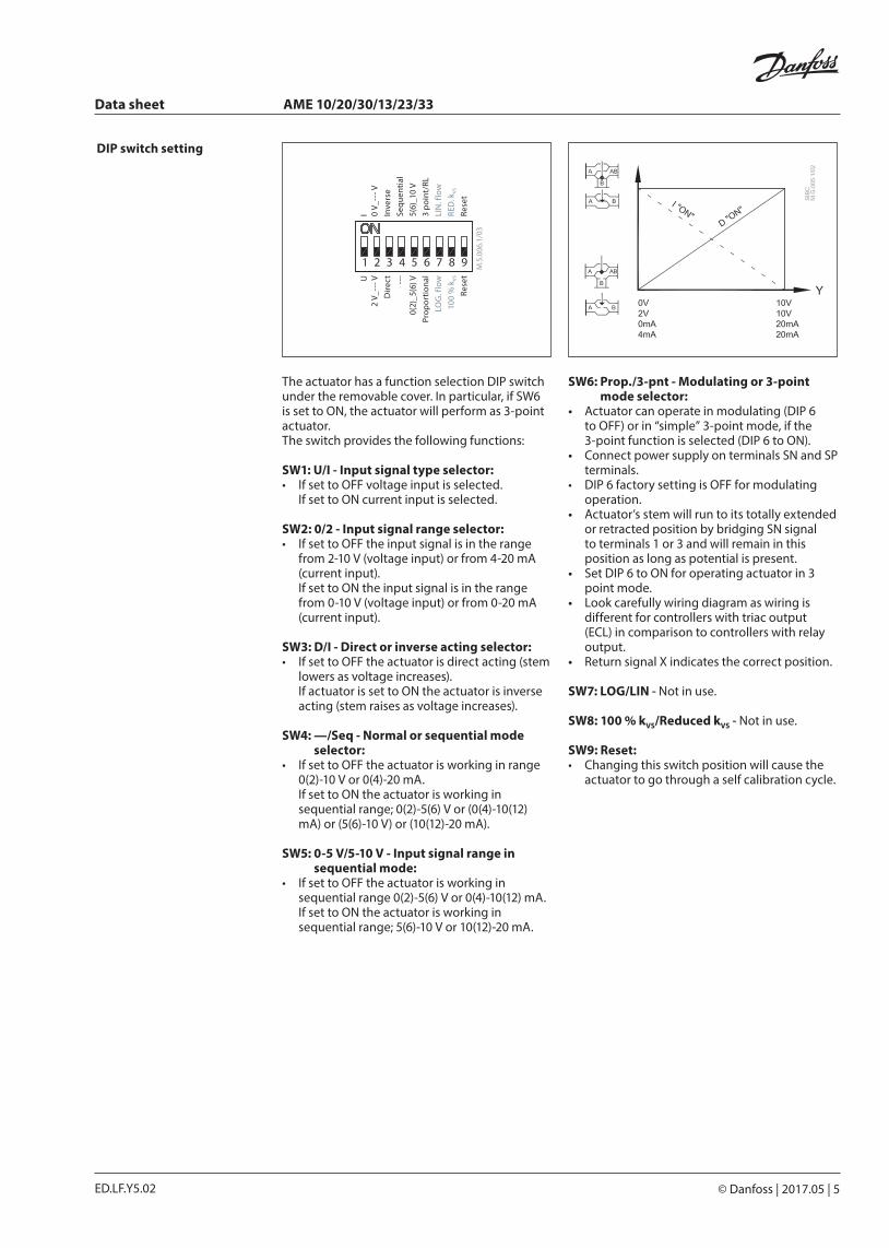
DIP switch setting
The actuator has a function selection DIP switch under the removable cover. In particular, if SW6 is set to ON, the actuator will perform as 3-point actuator. The switch provides the following functions:
SW1: U/I - Input signal type selector: • If set to OFF voltage input is selected.
If set to ON current input is selected.
SW2: 0/2 - Input signal range selector: • If set to OFF the input signal is in the range
from 2-10 V (voltage input) or from 4-20 mA (current input). If set to ON the input signal is in the range from 0-10 V (voltage input) or from 0-20 mA (current input).
SW3: D/I - Direct or inverse acting selector: • If set to OFF the actuator is direct acting (stem
lowers as voltage increases). If actuator is set to ON the actuator is inverse acting (stem raises as voltage increases).
SW4: —/Seq - Normal or sequential mode selector:
• If set to OFF the actuator is working in range 0(2)-10 V or 0(4)-20 mA. If set to ON the actuator is working in sequential range; 0(2)-5(6) V or (0(4)-10(12) mA) or (5(6)-10 V) or (10(12)-20 mA).
SW5: 0-5 V/5-10 V - Input signal range in sequential mode:
• If set to OFF the actuator is working in sequential range 0(2)-5(6) V or 0(4)-10(12) mA. If set to ON the actuator is working in sequential range; 5(6)-10 V or 10(12)-20 mA.
SW6: Prop./3-pnt - Modulating or 3-point mode selector:
• Actuator can operate in modulating (DIP 6 to OFF) or in “simple” 3-point mode, if the 3-point function is selected (DIP 6 to ON).
• Connect power supply on terminals SN and SP terminals.
• DIP 6 factory setting is OFF for modulating operation.
• Actuator’s stem will run to its totally extended or retracted position by bridging SN signal to terminals 1 or 3 and will remain in this position as long as potential is present.
• Set DIP 6 to ON for operating actuator in 3 point mode.
• Look carefully wiring diagram as wiring is different for controllers with triac output (ECL) in comparison to controllers with relay output.
• Return signal X indicates the correct position.
SW7: LOG/LIN - Not in use.
SW8: 100 % kVS/Reduced kVS - Not in use.
SW9: Reset: • Changing this switch position will cause the
actuator to go through a self calibration cycle.
Data sheet AME 10/20/30/13/23/33
6 | © Danfoss | 2017.05 ED.LF.Y5.02
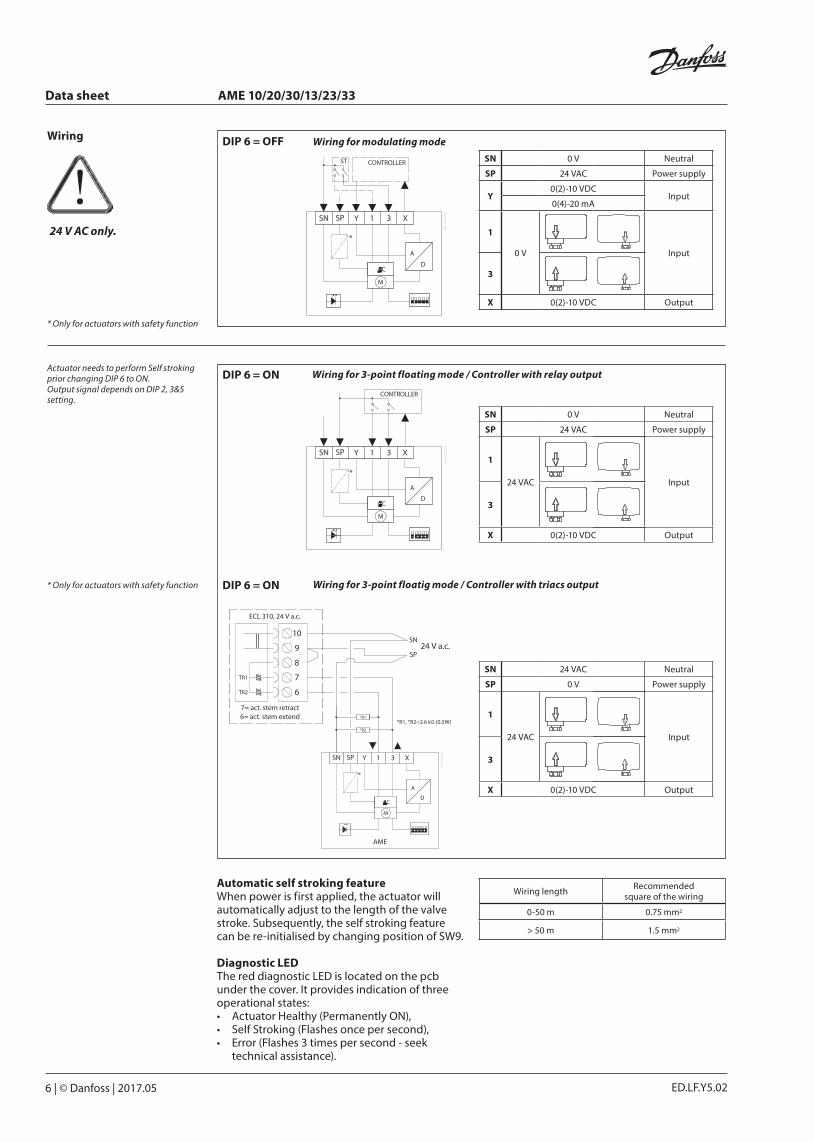
* Only for actuators with safety function
* Only for actuators with safety function
Automatic self stroking featureWhen power is first applied, the actuator will automatically adjust to the length of the valve stroke. Subsequently, the self stroking feature can be re-initialised by changing position of SW9.
Diagnostic LEDThe red diagnostic LED is located on the pcb under the cover. It provides indication of three operational states: • Actuator Healthy (Permanently ON), • Self Stroking (Flashes once per second), • Error (Flashes 3 times per second - seek
technical assistance).
Wiring
24 V AC only.
DIP 6 = OFF
SN 0 V Neutral
SP 24 VAC Power supply
1
24 VAC Input
3
X 0(2)-10 VDC Output
SN 24 VAC Neutral
SP 0 V Power supply
1
24 VAC Input
3
X 0(2)-10 VDC Output
Wiring for 3-point floating mode / Controller with relay output
Wiring for 3-point floatig mode / Controller with triacs output
DIP 6 = ON
DIP 6 = ON
Wiring length Recommendedsquare of the wiring
0-50 m 0.75 mm2
> 50 m 1.5 mm2
SN 0 V Neutral
SP 24 VAC Power supply
Y0(2)-10 VDC
Input0(4)-20 mA
1
0 V Input
3
X 0(2)-10 VDC Output
Wiring for modulating mode
Actuator needs to perform Self stroking prior changing DIP 6 to ON.Output signal depends on DIP 2, 3&5 setting.

Data sheet AME 10/20/30/13/23/33
© Danfoss | 2017.05 | 7ED.LF.Y5.02
121 83
107 min
. 200
121 83
110 m
in. 2
00
155
83
min. 160
47.5
120
120
min. 100
155
83
min. 160
47.5
16
120
min. 100
Dimensions AME 10
AME 13
AME 20, AME 30
AME 23, AME 33

ED.LF.Y5.028 | © Danfoss | DHS-SRMT/SI | 2017.05
Danfoss can accept no responsibility for possible errors in catalogues, brochures and other printed material. Danfoss reserves the right to alter its products without notice. This also applies to products already on order provided that such alterations can be made without subsequential changes being necessary eady agreed.All trademarks in this material are property of the respective companies. Danfoss and the Danfoss logotype are trademarks of Danfoss A/S. All rights reserved.
Data sheet AME 10/20/30/13/23/33
AME 10, AME 13 + AVQM (see AVQM data sheet)
AME 10, AME 13 + VM2 (DN 15 - 32)VS2 (DN 20* - 25)
AME 10 + VMV (DN 15 - 40)
AME 10, AME 13 + VB2 (DN 15 - 25)
AME 20/30, AME 23/33 +VM2 (DN 15 - 50)VS2 (DN 20* - 25)
AME 20/30, AME 23/33 + VB2 (DN 15 - 50)
AME 20/30, AME 23/33 + AVQM (see AVQM data sheet)
Actuator - valve combinations
* The use of AME actuators together with VS2 DN 15 is not recommendable. Linear characteristics as in VS2 DN 15 valves is not recommendable in DHW production.