Embed Size (px)
Citation preview
Data Sheet
Network Node with Gateway of INDIV-5 AMR
Application
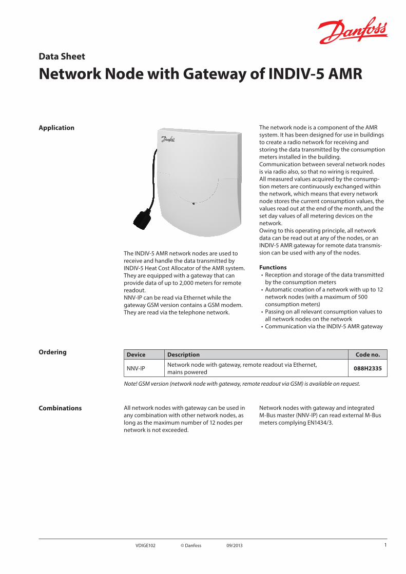
The INDIV-5 AMR network nodes are used to receive and handle the data transmitted by INDIV-5 Heat Cost Allocator of the AMR system. They are equipped with a gateway that can provide data of up to 2,000 meters for remote readout.NNV-IP can be read via Ethernet while the gateway GSM version contains a GSM modem. They are read via the telephone network.
The network node is a component of the AMR system. It has been designed for use in buildings to create a radio network for receiving and storing the data transmitted by the consumption meters installed in the building.Communication between several network nodes is via radio also, so that no wiring is required.All measured values acquired by the consump-tion meters are continuously exchanged within the network, which means that every network node stores the current consumption values, the values read out at the end of the month, and the set day values of all metering devices on the network.Owing to this operating principle, all network data can be read out at any of the nodes, or an INDIV-5 AMR gateway for remote data transmis-sion can be used with any of the nodes.
Functions• Reception and storage of the data transmitted
by the consumption meters• Automatic creation of a network with up to 12
network nodes (with a maximum of 500 consumption meters)
• Passing on all relevant consumption values to all network nodes on the network
• Communication via the INDIV-5 AMR gateway
Ordering Device Description Code no.
NNV-IP Network node with gateway, remote readout via Ethernet, mains powered 088H2335
Note! GSM version (network node with gateway, remote readout via GSM) is available on request.
Combinations All network nodes with gateway can be used in any combination with other network nodes, as long as the maximum number of 12 nodes per network is not exceeded.
Network nodes with gateway and integrated M-Bus master (NNV-IP) can read external M-Bus meters complying EN1434/3.
1VDIGE102 © Danfoss 09/2013

Data Sheet Network Node with Gateway of INDIV-5 AMR
Technical design The network node consists of the following blocks:
RS23
2
data base2000 meters
GSM1)
M-B
usM
aste
r5
unit
load
sTCP/IP2)
mains power supply
tran
scei
ver f
orA
MR
netw
ork
memory for500 meters
M-Bus(slave)
IrDA(optical)
Backup bt
1) GSM version only.2) NNV-IP only.
The transmitter and the receiver are used to collect data from the consumption meters and to forward these data to other nodes in the network. The memory stores the consumption data, and it is protected against temporary mains power failures by a backup battery.The network nodes are equipped with a gateway to store data of up to 2000 meters and to provide a possibility for remote readout via Ethernet or GSM. The gateway has an additional M-Bus master that can drive up to 5 additional external M-Bus unit loads (e.g. up to 5 additional M-Bus meters).Usually, however, the M-Bus master is used to connect nodes of different networks to be able to read more meters using only one gateway.For extension of M-Bus, is it possible to connect a repeater to the gateway. The gateway can be programmed using an additional RS232 interface.
Basic designThe network node consists of 2 major sections: the base and the housing with the electronics. It is thus possible to mount the base prior to commissioning, enabling the electrical installer to connect the network node with gateway to the mains network.At the time of commissioning, the electronics section is snapped on and the electrical connec-tions are made.
Electronics sectionThe electronics section is identical for all types of network nodes. It contains the network control elements:
RESET
MODE
DISPLAY
11
101 2 3 4 5
8
6
7
9
1. Connector for M-bus service connection2. Connector for RS232 module3. Plug terminal for the fixed M-bus connection4. Connector for power supply DC 3.6 V5. Connector for backup battery6. Operating mode button (MODE, red)7. Button for switching the display (DISPLAY, blue)8. Reset button (recessed)9. Display10. Connector (not for the user)11. Firmware memory (covered up)
Wall-mounted sectionThe wall-mounted section contains these components:
8
5
67 1
3
2 4
9
1. Connector for power supply DC 3.6 V2. Indication of mains supply (red LED)3. Permanently installed cable (no flexible cable!)4. SIM-card holder (GSM version only)5. RS232 interface for servicing6. Connector for M-bus service connection7. Screw terminal for the fixed M-bus connection8. Antenna (GSM version only)9. Indication of gateway status (green LED)
LED reaction
Blinking interval Explanation
≤ 1 sec. Gateway is booting / Error
> 1 sec. Gateway is ready for use
2 VDIGE102 © Danfoss 09/2013
Data Sheet Network Node with Gateway of INDIV-5 AMR
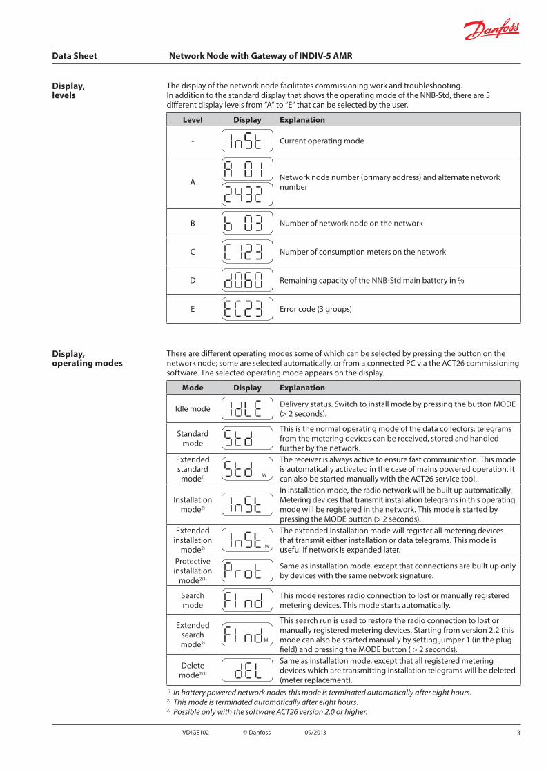
Display, levels
The display of the network node facilitates commissioning work and troubleshooting.In addition to the standard display that shows the operating mode of the NNB-Std, there are 5 different display levels from “A“ to “E“ that can be selected by the user.
Level Display Explanation
- Current operating mode
A Network node number (primary address) and alternate network number
B Number of network node on the network
C Number of consumption meters on the network
D Remaining capacity of the NNB-Std main battery in %
E Error code (3 groups)
Display, operating modes
There are different operating modes some of which can be selected by pressing the button on the network node; some are selected automatically, or from a connected PC via the ACT26 commissioning software. The selected operating mode appears on the display.
Mode Display Explanation
Idle mode Delivery status. Switch to install mode by pressing the button MODE (> 2 seconds).
Standard mode
This is the normal operating mode of the data collectors: telegrams from the metering devices can be received, stored and handled further by the network.
Extended standard
mode1)
M
The receiver is always active to ensure fast communication. This mode is automatically activated in the case of mains powered operation. It can also be started manually with the ACT26 service tool.
Installation mode2)
In installation mode, the radio network will be built up automatically. Metering devices that transmit installation telegrams in this operating mode will be registered in the network. This mode is started by pressing the MODE button (> 2 seconds).
Extended installation
mode2)
M
The extended Installation mode will register all metering devices that transmit either installation or data telegrams. This mode is useful if network is expanded later.
Protective installation
mode2)3)
Same as installation mode, except that connections are built up only by devices with the same network signature.
Search mode
This mode restores radio connection to lost or manually registered metering devices. This mode starts automatically.
Extended search mode2)
M
This search run is used to restore the radio connection to lost or manually registered metering devices. Starting from version 2.2 this mode can also be started manually by setting jumper 1 (in the plug field) and pressing the MODE button ( > 2 seconds).
Delete mode2)3)
Same as installation mode, except that all registered metering devices which are transmitting installation telegrams will be deleted (meter replacement).
1) In battery powered network nodes this mode is terminated automatically after eight hours.2) This mode is terminated automatically after eight hours.3) Possible only with the software ACT26 version 2.0 or higher.
3VDIGE102 © Danfoss 09/2013

Data Sheet Network Node with Gateway of INDIV-5 AMR
State Display Explanation
Remote access
C During remote access the symbol " C" will be displayed.
High speed mode
for example
M
When all network nodes have switched on their receivers for fast data exchange, this will be displayed as two dots in the upper part of the LCD.
Busconnection
(from version 2.2)
for example
If a connection to a bus is being built up, the number of the bus and the primary address of this bus will be briefly displayed .In the example, network node 03 is connected to M- Bus.
IrDA master mode (from version 2.2)
This mode is started by pressing the button MODE (< 0.5 seconds). It indicates readiness to connect additional IrDA devices (in IrDA Slave mode). This mode stops after 10 seconds.
Add (from version 2.2)
for example
If an unregistered IrDA-capable metering device is connected in IrDA master mode, it can be inserted into the network node by pressing the button DISPLAY while ADD is displayed. The last 4 digits of device number are indicated (e.g. 20000123).The registration of the device takes place and search mode starts.
Delete (from version 2.2)
for example
If an already registered IrDA-capable metering device is connected in IrDA-master mode it can be removed from the network node by pressing the button DISPLAY while DEL is displayed. The last 4 digits of device number are indicated (e.g. 20000123).The removal of the device takes place and if necessary search mode is stopped.
Copy (from version 2.2)
for example If a new network node (running in idle mode) is connected in IrDA-master mode, it is possible to make a copy of all network data into the new node by pressing the button DISPLAY while COPY is displayed.Copying lasts up to 20 minutes. At the end "StArt Prot" is displayed on LCD of the new network node for 1 hour. After mounting the new node the protected mode is also started by pressing the DISPLAY button. By this procedure the new network node is integrated in network and search mode is started automatically.
Display, state of the system
4 VDIGE102 © Danfoss 09/2013
Data Sheet Network Node with Gateway of INDIV-5 AMR
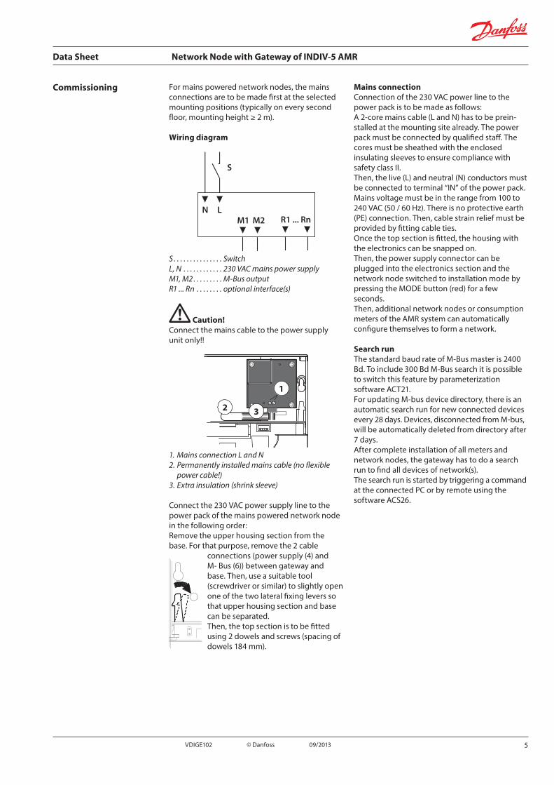
Commissioning For mains powered network nodes, the mains connections are to be made first at the selected mounting positions (typically on every second floor, mounting height ≥ 2 m).
Wiring diagram
S
N LR1 ... RnM1 M2
S . . . . . . . . . . . . . . . SwitchL, N . . . . . . . . . . . . 230 VAC mains power supplyM1, M2 . . . . . . . . . M-Bus outputR1 ... Rn . . . . . . . . optional interface(s)
Caution!Connect the mains cable to the power supply unit only!!
1
2 3
1. Mains connection L and N2. Permanently installed mains cable (no flexible
power cable!)3. Extra insulation (shrink sleeve)
Connect the 230 VAC power supply line to the power pack of the mains powered network node in the following order:Remove the upper housing section from the base. For that purpose, remove the 2 cable
connections (power supply (4) and M- Bus (6)) between gateway and base. Then, use a suitable tool (screwdriver or similar) to slightly open one of the two lateral fixing levers so that upper housing section and base can be separated.Then, the top section is to be fitted using 2 dowels and screws (spacing of dowels 184 mm).
Mains connectionConnection of the 230 VAC power line to the power pack is to be made as follows:A 2-core mains cable (L and N) has to be prein-stalled at the mounting site already. The power pack must be connected by qualified staff. The cores must be sheathed with the enclosed insulating sleeves to ensure compliance with safety class II.Then, the live (L) and neutral (N) conductors must be connected to terminal “IN” of the power pack. Mains voltage must be in the range from 100 to 240 VAC (50 / 60 Hz). There is no protective earth (PE) connection. Then, cable strain relief must be provided by fitting cable ties.Once the top section is fitted, the housing with the electronics can be snapped on.Then, the power supply connector can be plugged into the electronics section and the network node switched to installation mode by pressing the MODE button (red) for a few seconds.Then, additional network nodes or consumption meters of the AMR system can automatically configure themselves to form a network.
Search runThe standard baud rate of M-Bus master is 2400 Bd. To include 300 Bd M-Bus search it is possible to switch this feature by parameterization software ACT21.For updating M-bus device directory, there is an automatic search run for new connected devices every 28 days. Devices, disconnected from M-bus, will be automatically deleted from directory after 7 days.After complete installation of all meters and network nodes, the gateway has to do a search run to find all devices of network(s).The search run is started by triggering a command at the connected PC or by remote using the software ACS26.
5VDIGE102 © Danfoss 09/2013

Data Sheet Network Node with Gateway of INDIV-5 AMR
GSM version AntennaScrew tight the GSM antenna prior to commis-sioning.
SIM cardThe GSM version of network node with gateway requires a SIM card and GSM service contracts for voice- and data service. SIM cards, only sold for voice service or M2M service, cannot be used.
Remove the upper section of the GSM version from the base. Press the SIM card slightly in the slot at the bottom of the gateway. Ensure that the chamfered corner is in the correct position.
1 2
1. SIM card.2. Card ejector.
NNV-IP The NNV-IP network node features an Ethernet interface, which connects to the outside world via an RJ45 connector, where the network cable is to be connected.The distance to the network conduit box may not exceed 2 meters.It is possible, to choose fixed or dynamic (DHCP) IP addresses for WAN communication. The transmission in WAN can be done secured by SSL or unsecured.
Parameter settingThe network node with gateway is parameterized with the ACT21 software. The scope of delivery of the software includes an RS232 cable for connecting the PC to the gateway.
SealingOn completion of commissioning, secure the network node with the seal provided. Insert the seal in the opening to the right of the network node.
Safety notesAfter opening the housing, certain parts of the device / system that become accessible carry dangerous voltage. Only qualified staff may interfere with such devices / systems.• To ensure correct and safe operation, the
product must be adequately shipped, stored, installed, operated and maintained.
• Staff dealing with the product must be familiar with all potential hazards and maintenance measures in accordance with the instructions given in this document.
• It must be possible to disconnect the device from the power supply at an easily accessible point (e.g. a switch in the power cable).
• The connection cable has to be protected by an appropriate fuse. Whenever performing any work on the network node, disconnect the device from the mains supply.
Non-observance of these warning notes can lead to personal injury or damage to property!
Ensure that the local regulations for radio transmission installations and electrical installations are complied with.
6 VDIGE102 © Danfoss 09/2013

Data Sheet Network Node with Gateway of INDIV-5 AMR
M-Bus connection Each network node has a plug terminal for a permanently installed M-Bus connection.A fitting plug is included.
1. Permanently connected M-Bus, max. 5 unit loads.
2. Temporary M-Bus connection to gateway.
MODE2
1
Technical dataProtection class NNV-IP: IP21
GSM version: IP 32
Safety class 2
CE conformity to EMC directives
Electromagnetic immunity according to EN 55 024 / EN 301 489
Electromagnetic emissions according to EN 55 022 / EN 300 220-1
Operating voltage, mains powered version 100 - 240 VAC, 50/60 Hz
Rated frequency 868.95 MHz
Transmitter power < 14 dBm
Frequency of transmission < 1%
Transport / Storage temperature -20 to +60 °C (recommended < 30 °C)
Operation temperature 0 to 55 °C
Weight 0.3 kg
Dimensions20018455
250
150
100
R 15
0R
60
R 25
0
31.8
2.5
R 250
9.7
7VDIGE102 © Danfoss 09/2013

Data Sheet Network Node with Gateway of INDIV-5 AMR
8 VDIGE102 © Danfoss 09/2013