Embed Size (px)
Citation preview
© Danfoss | 2016.04 VD.CA.M4.02 | 1
Pressure relief controller AFA / VFG 2(1) (PN 16, 25, 40)
Data sheet
Description
VFG 2 Valves (metallic sealing cone)
PictureDN kVS Tmax Code No. Tmax Code No.
(mm) (m3 /h) (°C) PN 16 (°C) PN 25 PN 40
15 4,0
1501)
065B2388
2001)
065B2401 065B2411
20 6,3 065B2389 065B2402 065B2412
25 8,0 065B2390 065B2403 065B2413
32 16 065B2391 065B2404 065B2414
40 20 065B2392 065B2405 065B2415
50 32 065B2393 065B2406 065B2416
65 50 065B2394 065B2407 065B2417
80 80 065B2395 065B2408 065B2418
100 125 065B2396 065B2409 065B2419
125 160 065B2397 065B2410 065B2420
150 280
1401)
065B2398
1401)
– 065B2421
200 320 065B2399 – 065B2422
250 400 065B2400 – 065B2423
150 280
1501)
065B2424
2001)
– On request
200 320 065B2425 – On request
250 400 065B2426 – On request
1) at temperatures above 150 °C (DN 15-125)/140 °C (DN 150-250) only with seal pots (see Accessories)
Ordering
Example 1:Pressure relief controller; DN 15; kVS 4,0; metallic sealing; PN 16; setting range 0,15-1,2 bar; Tmax 150 °C; flange;
– 1× VFG 2 DN 15 valve Code no: 065B2388– 1× AFA actuator Code no: 003G1011– 1× Impulse tube set AF Code no: 003G1391
Impulse tube set AF
The controller is a self-acting pressure relief controller primarily for use in district heating systems. The controller is normally closed and opens on rising pressure.
The controller has a control valve, an actuator with one control diaphragm and a spring(s) for pressure setting.
Further on two valve versions are available:– VFG 2 with metallic sealing cone– VFG 21 with soft sealing cone
Main data:∙ DN 15-250∙ kVS 4,0-400 m3/h∙ PN 16, 25, 40∙ Setting range:
– 0,05-0,35 bar / 0,1-0,6 bar / 0,15-1,2 bar / 0,5-2,5 bar / 1-5 bar / 3-11 bar / 10-16 bar
∙ Temperature:– Circulation water / glycolic water up to 30 %:
2 … 140 / 150 / 200 °C∙ Connections:
– Flange
Data sheet Pressure relief controller AFA/VFG 2(1) (PN 16, 25, 40)
2 | © Danfoss | 2016.04 VD.CA.M4.02
VFG 21 Valves (soft sealing cone)
PictureDN kVS Tmax
ConnectionsCode No,
(mm) (m3/h) (°C) PN 16
15 4,0
150
Flanges acc, to EN 1092-1
065B2502
20 6,3 065B2503
25 8,0 065B2504
32 16 065B2505
40 20 065B2506
50 32 065B2507
65 50 065B2508
80 80 065B2509
100 125 065B2510
125 160 065B2511
150 280
140
065B2512
200 320 065B2513
250 400 065B2514
Note: other valves available on special request,
AFA ActuatorsPicture ∆p setting range (bar) for DN Code No,
10-16
15-125
003G1007
3-11 003G1008
1-5 003G1009
0,5-2,5 003G1010
0,15-1,2
15-250
003G1011
0,1-0,6 003G1012
0,05-0,35 003G1013
AccessoriesPicture Type designation Description Connections Code No,
Impulse tube set AF
– 1× Copper tube Ø10 × 1 × 1500 mm– 1 × compression fitting for imp, tube connection to pipe (G 1/4)
– 2 × socket
– 003G1391
Seal pot V1 1) Capacity 1 liter; with compression fittings for imp, tube Ø10
– 003G1392
Seal pot V2 1) Capacity 3 liter; with compression fittings for imp, tube Ø10, for actuator size 630 cm2 – 003G1403
Compression fitting 2) For impulse tube Ø10 connections to controller
G 1/4 003G1468
Shut off valveFor impulse tube Ø10 –
003G1401
Throttle valve 065B2909
1) Seal pot has to be used on impulse tubes always when Tmax ≥ 150 °C (DN 15-125) / 140 °C (DN 150 -250) 2) Consist of a nipple, compression ring and nut
Ordering (continuous)
Example 2:Pressure relief controller; DN 15; kVS 4,0; metallic sealing; PN 25; setting range 0,15-1,2 bar; Tmax 200 °C; flange;
– 1× VFG 2 DN 15 valve Code no: 065B2401– 1× AFA actuator Code no: 003G1011– 1× Impulse tube set AF Code no: 003G1391– 1× Seal pot V1 Code no: 003G1392
Products will be delivered separatly.
Impulse tube set AF
Seal pot V1
Data sheet Pressure relief controller AFA/VFG 2(1) (PN 16, 25, 40)
© Danfoss | 2016.04 | 3VD.CA.M4.02
Technical data ValveNominal diameter DN 15 20 25 32 40 50 65 80 100 125 150 200 250
kVS value m3/h 4,0 6,3 8,0 16 20 32 50 80 125 160 280 320 400
Cavitation factor z 0,6 0,6 0,6 0,55 0,55 0,5 0,5 0,45 0,4 0,35 0,3 0,2 0,2
Leakage acc. to standard IEC 534 (% of kVS)
VFG 2 ≤ 0,03 ≤ 0,05
VFG 21 ≤ 0,01
Nominal pressure PN 16, 25, 40
Max. differential pressure
PN 16 bar 1615 12 10
PN 25, 40 20
Media Circulation water / glycolic water up to 30 %
Media pH Min. 7, max. 10
Media temperature VFG 2 °C 2 … 150 / 2 … 200 1) 2 … 140 /2 … 150 (200 2))
VFG 21 2 … 150 2 … 140
Connections Flange
Materials
Valve body PN 16 Grey cast iron EN-GJL-250 (GG-25)
PN 25 Ductile iron EN-GJS-400(GGG-40.3)
PN 40 Cast steel GP240GH (GS-C 25)
Valve seat Stainless steel, mat. No. 1.4021 Stainless steel, mat. No. 1.4313
Valve coneStainless steel, mat. No. 1.4404 Stainless steel,
mat. No. 1.4021
Sealing VFG 2 Metal
VFG 21 EPDM
Pressure relieve system Bellows (Stainless steel, mat. No. 1.4571) Diaphragm (EPDM)
1) at temperatures above 150 °C (DN 15-125)/140 °C (DN150-250) only with seal pots (see Accessories)2) on request
ActuatorActuator size cm2 32 80 250 630
Max. operating pressure bar 25 16
Diff. pressure setting ranges and spring colours
barblack silver silver yellow silver yellow yellow
10 – 16 3 – 11 1 – 5 0,5-2,5 0,15-1,2 0,1 – 0,6 0,05 – 0,35
Materials
Actuator housing Stainless steel, mat. No. 1.0338, zinc plated and yellow chromate
Control diaphragm EPDM (Rolling; fibre enforced)
Service kits
Picture Type designationDN kVS Code No.
(mm) (m3/h) for VFG 2 for VFG 21
Valve insert
15 4,0 065B2796 065B2790
20 6,3 065B2797 065B2791
25 8065B2798 065B2792
32 16
40 20065B2799 065B2793
50 32
65 50065B2800 065B2894
80 80
100 125065B2801 065B2895
125 160
150 280 065B2964 065B2966
250 400 065B2965 –
Stuffing cone (with EPDM O-rings) 003G1464
Ordering (continuous)
Data sheet Pressure relief controller AFA/VFG 2(1) (PN 16, 25, 40)
4 | © Danfoss | 2016.04 VD.CA.M4.02
Installation position
DN 15-80 Tmax ≤ 120 °C DN 15-80 Tmax > 120 °C; DN 100-250
DN 15-80 Tmax ≤ 120 °C
The controllers can be installed in any position.
DN 15-80 Tmax > 120 °C; DN 100-250
The controllers can be installed in horizontal pipes only, with a pressure actuator oriented downwards.
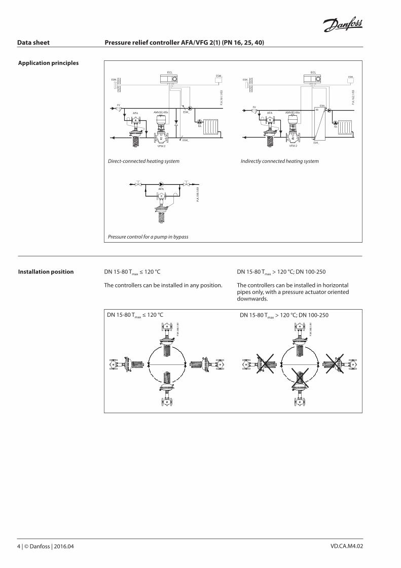
Application principles
Pressure control for a pump in bypass
Direct-connected heating system Indirectly connected heating system
Data sheet Pressure relief controller AFA/VFG 2(1) (PN 16, 25, 40)
© Danfoss | 2016.04 | 5VD.CA.M4.02
EN-GJL-250 (GG-25)
PN 16
PN 25
EN-GJS-400 (GGG-40.3)
PN 40
EN-GP-240-GH (GS-C 25)
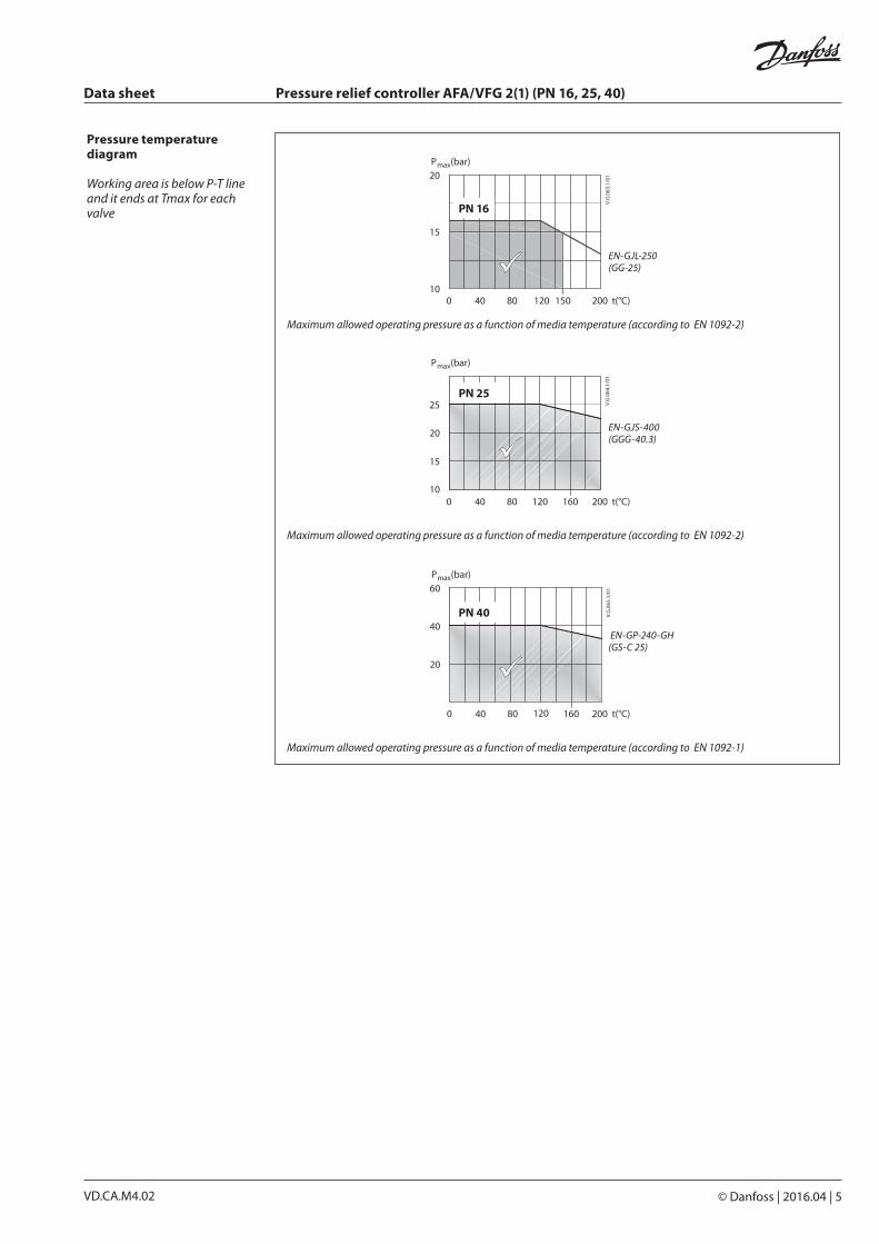
Pressure temperature diagram
Working area is below P-T line and it ends at Tmax for each valve
Maximum allowed operating pressure as a function of media temperature (according to EN 1092-2)
Maximum allowed operating pressure as a function of media temperature (according to EN 1092-1)
Maximum allowed operating pressure as a function of media temperature (according to EN 1092-2)
Data sheet Pressure relief controller AFA/VFG 2(1) (PN 16, 25, 40)
6 | © Danfoss | 2016.04 VD.CA.M4.02
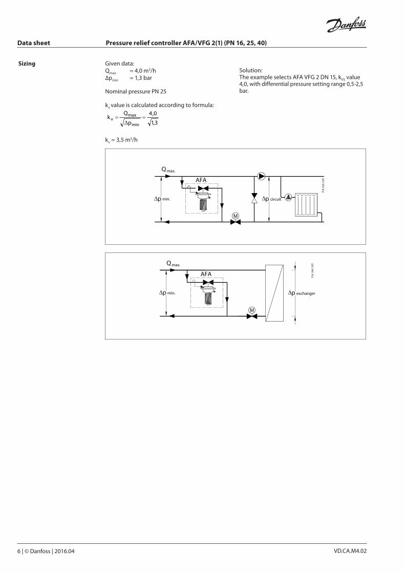
Sizing Given data: Qmax = 4,0 m3/h∆pmin = 1,3 bar
Nominal pressure PN 25
kv value is calculated according to formula:
3,1
0,4
p
Qk
min
maxv
kv = 3,5 m3/h
Solution: The example selects AFA VFG 2 DN 15, kVS value 4,0, with differential pressure setting range 0,5-2,5 bar.
Data sheet Pressure relief controller AFA/VFG 2(1) (PN 16, 25, 40)
© Danfoss | 2016.04 | 7VD.CA.M4.02
10
11
12
2
63
1
16
8
14
4
7
15
2117
13
5
19
9
2
182092
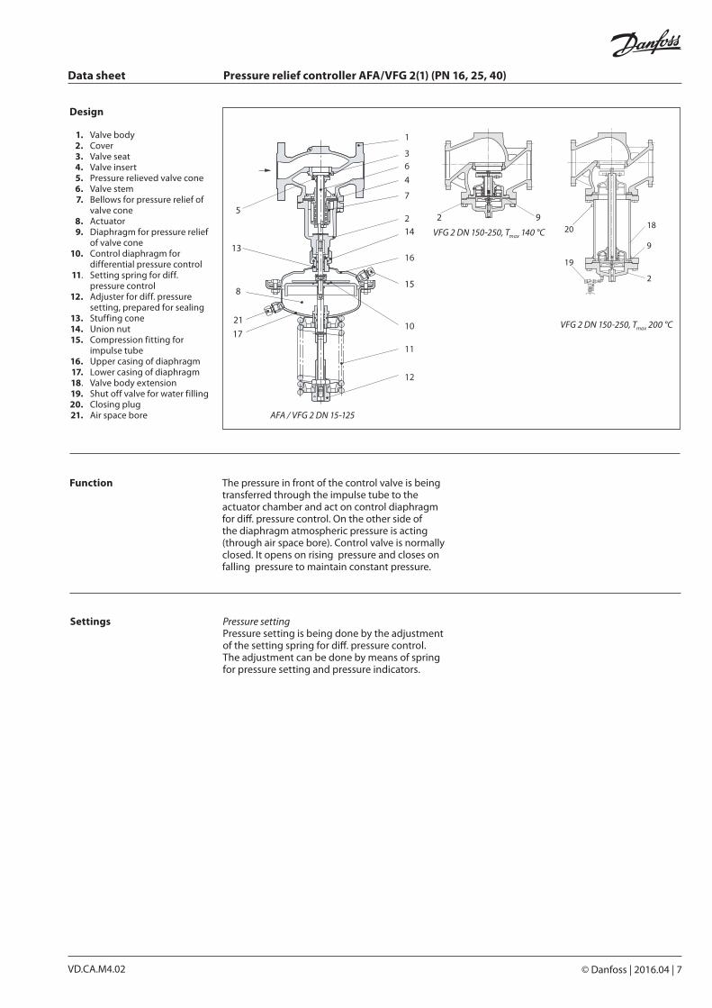
VFG 2 DN 150-250, Tmax 140 °C
VFG 2 DN 150-250, Tmax 200 °C
Design
1. Valve body 2. Cover 3. Valve seat 4. Valve insert 5. Pressure relieved valve cone 6. Valve stem 7. Bellows for pressure relief of
valve cone 8. Actuator 9. Diaphragm for pressure relief
of valve cone 10. Control diaphragm for
differential pressure control 11. Setting spring for diff.
pressure control 12. Adjuster for diff. pressure
setting, prepared for sealing 13. Stuffing cone 14. Union nut 15. Compression fitting for
impulse tube 16. Upper casing of diaphragm 17. Lower casing of diaphragm 18. Valve body extension 19. Shut off valve for water filling 20. Closing plug 21. Air space bore AFA / VFG 2 DN 15-125
The pressure in front of the control valve is being transferred through the impulse tube to the actuator chamber and act on control diaphragm for diff. pressure control. On the other side of the diaphragm atmospheric pressure is acting (through air space bore). Control valve is normally closed. It opens on rising pressure and closes on falling pressure to maintain constant pressure.
Function
Settings Pressure settingPressure setting is being done by the adjustment of the setting spring for diff. pressure control. The adjustment can be done by means of spring for pressure setting and pressure indicators.
VD.CA.M4.028 | © Danfoss | DHS-SRMT/SI | 2016.04
Danfoss can accept no responsibility for possible errors in catalogues, brochures and other printed material. Danfoss reserves the right to alter its products without notice. This also applies to products already on order provided that such alterations can be made without subsequential changes being necessary eady agreed.All trademarks in this material are property of the respective companies. Danfoss and the Danfoss logotype are trademarks of Danfoss A/S. All rights reserved.
Data sheet Pressure relief controller AFA/VFG 2(1) (PN 16, 25, 40)
L
H
B
L
B
H
L
B 1
H1
A
H
78
110
SW 2
2
ø60
Shut off valve
240
Ø 8
9
Seal pot V1
298
Ø 1
40
Seal pot V2
Compression fitting
SW19
40
Ø10
G1/4
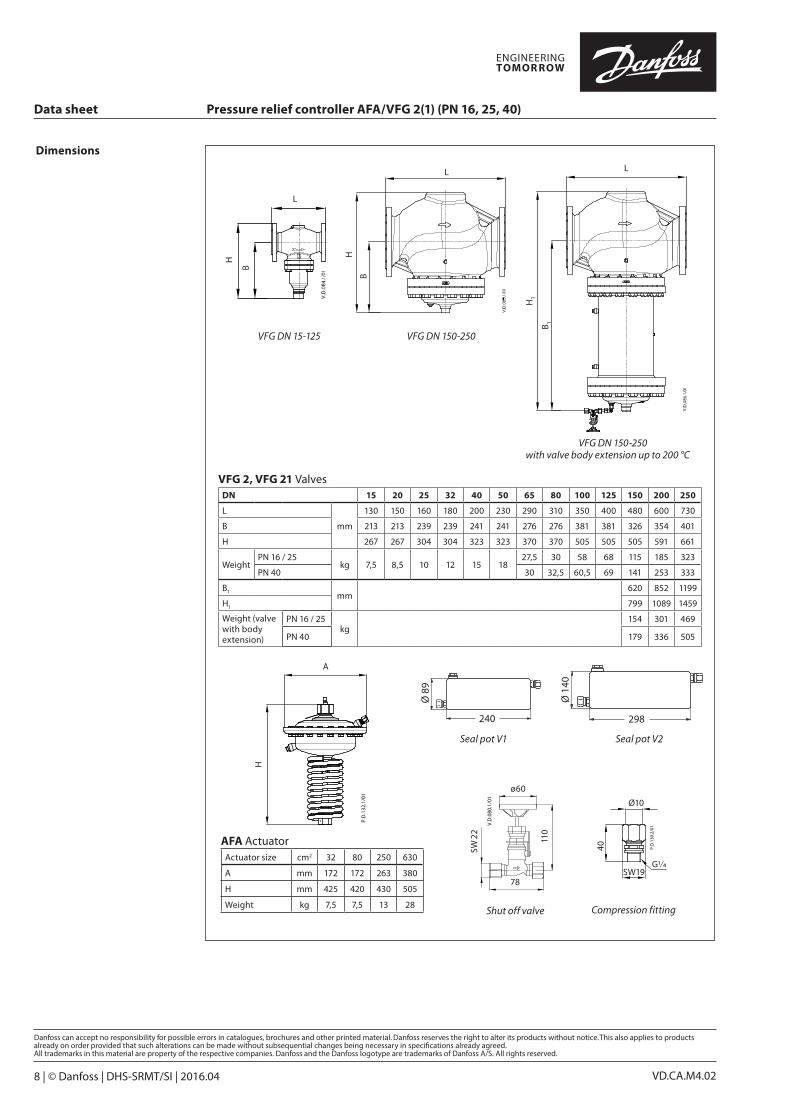
Dimensions
AFA ActuatorActuator size cm2 32 80 250 630
A mm 172 172 263 380
H mm 425 420 430 505
Weight kg 7,5 7,5 13 28
VFG DN 15-125 VFG DN 150-250
VFG DN 150-250 with valve body extension up to 200 °C
VFG 2, VFG 21 ValvesDN 15 20 25 32 40 50 65 80 100 125 150 200 250
L
mm
130 150 160 180 200 230 290 310 350 400 480 600 730
B 213 213 239 239 241 241 276 276 381 381 326 354 401
H 267 267 304 304 323 323 370 370 505 505 505 591 661
WeightPN 16 / 25
kg 7,5 8,5 10 12 15 1827,5 30 58 68 115 185 323
PN 40 30 32,5 60,5 69 141 253 333
B1mm
620 852 1199
H1 799 1089 1459
Weight (valve with body extension)
PN 16 / 25kg
154 301 469
PN 40 179 336 505


![ljBfno vfg]kfgL, ;/;kmfO tyf :jR5tf ;DjGwL sfo{ljlw, -bf ...doe.gov.np/assets/uploads/files/f86b568c... · s_ ljBfno vfg]kfgLM ljwfno vfg]kfgL eGgfn] 5fq, 5fqf, lzIfs, sd{rf/L nufotsf](https://img.pdfslide.net/doc/110x75/5f87f8e21fe3ba51c6560c10/ljbfno-vfgkfgl-kmfo-tyf-jr5tf-djgwl-sfoljlw-bf-doegovnpassetsuploadsfilesf86b568c.jpg)
![vfg]kfgL ;'/Iff of]hgf xft] k'l:tsf€¦ · vfg]kfgL ;'/Iff of]hgf xft] k'l:tsf g]kfn ;/sf/;x/L ljsf; dGqfno vfg]kfgL tyf 9n lgsf; ljefu @)&) g]kfn ;/sf/ vfg]kfgL tyf ;/;kmfO dGqfno](https://img.pdfslide.net/doc/110x75/5f87fa2a65e23b2a8528fc4e/vfgkfgl-iff-ofhgf-xft-kltsf-vfgkfgl-iff-ofhgf-xft-kltsf-gkfn-sfxl.jpg)