Embed Size (px)
Citation preview

DATA SHEET
MS1000_IT_EN_DS004REV08
MS 1000


MS1000_IT_EN_DS004REV08
INDEX
TECHNICAL DATA ____________________________________________________________________2
OVERALL FEATURES __________________________________________________________________2
STANDARD FEATURES ________________________________________________________________2
NOTES FOR PED DIRECTIVE FOR SENSOR ________________________________________________3
OVERALL DIMENSIONS _______________________________________________________________4
SENSOR VERSIONS/JUNTION BOX ______________________________________________________5
SEPARATE VERSION__________________________________________________________________6
INSTALLATION RECOMMENDATIONS ____________________________________________________7
RECOMMENDED INSTALLATION PROCEDURE ______________________________________________8
SENSOR GROUNDING ________________________________________________________________9
PRESSURE LOSS CALCULATION (CONES 8° ANGLES) _______________________________________10
HOW TO ORDER ____________________________________________________________________11

The
man
ufac
ture
r gu
aran
tees
onl
y En
glis
h te
xt a
vaila
ble
on o
ur w
eb s
ite w
ww
.isoi
l.com
MS1000_IT_EN_DS004REV081 di 13

The
man
ufac
ture
r gu
aran
tees
onl
y En
glis
h te
xt a
vaila
ble
on o
ur w
eb s
ite w
ww
.isoi
l.com
MS1000_IT_EN_DS004REV082 di 13
OVERALL FEATURESNominal diameter � DN 25 ÷ 400
Minimum conductivity � 5 mS/cm
Humidity Range � 0÷100% (IP 67)
Accuracy � See relevant converter data sheet
CE Certification � Yes
STANDARD FEATURESBody material � Carbon steel painted
Nominal pressure � 1600 kPa : all with PP and Ebonite lining � 4000 kPa : PTFE lining up to DN 150
Process connection � Wafer Type
Version – protection rating � Compact IP67
Body material � Carbon Steel
Lining material � Polypropylene (max PN 16) � Ebonite (DN 200 – 400) � PTFE (DN 25 – 150)
Gasket material (ONLY for lining in Polypropylene ) � FPM
Liquid temperature � 0°C ÷ 60°C with PP lining � -5°C ÷ 80°C with ebonite lining � -20°C ÷ 100°C with PTFE lining in compact version
Vacuum resistance � 20 Kpa (absolute) at 100 °C (60/80°C for PP/Ebonite)
Electrodes material
� Stainless steel AISI 316 � Hastelloy C � Platinum-rhodium � Titanium � Tantalum
OPTIONAL FEATURES (CHECK FOR MORE DETAILS ‘HOW TO ORDER’ ON LAST PAGE)
Body material � Stainless steel AISI 304 or 316
Gasket material (ONLY for lining in Polypropylene ) � EPDM
Liquid temperature � -20°C ÷ 110°C with PTFE lining in separate version* * Contattare il costruttore per temperature più alte
Lining material � On request
Electrodes material � On request
Version – protection rating � Separate version (max 20m) – IP 68 � Separate version (max 500 m), with preamplifier – IP 67 � Separate version (max 500 m), with preamplifier – IP 68
T E C H N I C A L D A T A

The
man
ufac
ture
r gu
aran
tees
onl
y En
glis
h te
xt a
vaila
ble
on o
ur w
eb s
ite w
ww
.isoi
l.com
MS1000_IT_EN_DS004REV083 di 13
N O T E S F O R P E D D I R E C T I V E F O R S E N S O R
Here below the tables of products subject to Directive Pressure Equipment Device 2014/68/UE (PED) implemented by legislative decree February 15, 2016, n. 26
The tables show which category of PED is applicable according to the water operating temperature (TAB A T <110 ° C TAB B T> = 110 ° C), sensor’s DN and its nominal pressure.
tab. aped directive for water with temperature <110°c
all lining : pp, ebonite,ptfe
DN NOMINAL PRESSURE (PN)16 40
25 E E32 E E40 E E50 E E65 E E80 E E
100 E E125 E E150 E E200 E E250 I E300 I E350 I E400 I E
tab. bped directive for water with temperature >=110°c
only ptfe lining
DN NOMINAL PRESSURE (PN)16 40
25 E E32 E E40 II II50 I II65 I II80 I II
100 I II125 I II150 I II200 I E250 II E300 II E350 III E400 III E
legendaE EXCEPT FROM DIRECTIVEI PED CAT. III PED CAT. IIIII PED CAT. III
For products that falls in category I, is valid the declaration of conformity available on the following page; the products in Category II and III are supplied with a specific declaration of conformity for each instrument

The
man
ufac
ture
r gu
aran
tees
onl
y En
glis
h te
xt a
vaila
ble
on o
ur w
eb s
ite w
ww
.isoi
l.com
MS1000_IT_EN_DS004REV084 di 13
O V E R A L L D I M E N S I O N S
DN
G
L
D
H
70
25
mm (inches)
DN
25(1”)
32(1” 1/4)
40(1” 1/2)
50(2”)
65(2” 1/2)
80(3”)
100(4”)
125(5”)
150(6”)
200 (8”)
250 (10”)
300 (12”)
350 (14”)
400 (16”)
L
+0 +0 +0 +0 +0 +0 +0 +0 +0 +0 +0 +0 +0 +0
-3 (-0.12)
-3 (-0.12)
-3 (-0.12)
-3 (-0.12)
-3 (-0.12)
-3 (-0.12)
-3 (-0.12)
-3 (-0.12)
-3 (-0.12)
-3 (-0.12)
-5(-0.20)
-5 (-0.20)
-5 (-0.20)
-5 (-0.20)
100(3.94)
100(3.94)
100(3.94)
100(3.94)
150(5.90)
150(5.90)
150(5.90)
180(7.09)
180(7.09)
200(7.87)
250(9.84)
300(11.81)
350(13.78)
400(15.75)
H 147(5.79)
153(6.02)
161(6.34)
177(6.97)
199(7.83)
209(8.23)
235(9.25)
263(10.35)
291(11.46)
362(14.25)
417(16.42)
467(18.39)
527(20.75)
579(22.80)
D 62(2.20)
67(2.44)
78(2.76)
92(3.39)
108(4.25)
118(4.65)
144(5.67)
172(6.77)
200(7.87)
271(10.67)
326(12.83)
376(14.80)
436(17.17)
488(19.21)
G - - - - - - - - - 144(5.67)
194(7.64)
244(9.60)
294(11.57)
344(13.54)
Weight kg (lbs)
1.2(2.64)
1.6(3.52)
1.8(3.96)
2(4.4)
3.6(7.92)
3.8(8.36)
5(11)
7.8(17.16)
8.2(18)
18.2(40)
24(53)
27(59)
32(70)
39(86)
Flanges available
PTFE-EBANITE: PN10, PN16, PN25, PN40, ANSI150, ANSI,300 PP: PN10, PN16, ANSI150 PTFE-EBANITE: PN10, PN16, ANSI150

The
man
ufac
ture
r gu
aran
tees
onl
y En
glis
h te
xt a
vaila
ble
on o
ur w
eb s
ite w
ww
.isoi
l.com
MS1000_IT_EN_DS004REV085 di 13
PRICE LIST OPTIONS JUNCTION BOX TYPE(surface finish)
A Without junction box, converter connected on the connections box
B A-1 A-2 only for ML110
G A-4
F A-3
N A-2 with preamplifer
Q A-4 with preamplifer
U B-1 (raw) B-2 only for ML110 (raw)
S B-4 (raw)
T B-3 (raw)
P B-2 with preamplifer (raw)
R B-4 with preamplifer (raw)
K B-1 (polished) B-2 only for ML110 (polished)
Y B-4 (polished)
W B-3 (polished)
V B-2 with preamplifer (polished)
J B-4 with preamplifer (polished)
1 2 3 4
APAINTED
ALUMINIUM
BAISI 304
S E N S O R V E R S I O N S / J U N T I O N B O X
The
man
ufac
ture
r gu
aran
tees
onl
y En
glis
h te
xt a
vaila
ble
on o
ur w
eb s
ite w
ww
.isoi
l.com
MS1000_IT_EN_DS004REV086 di 13
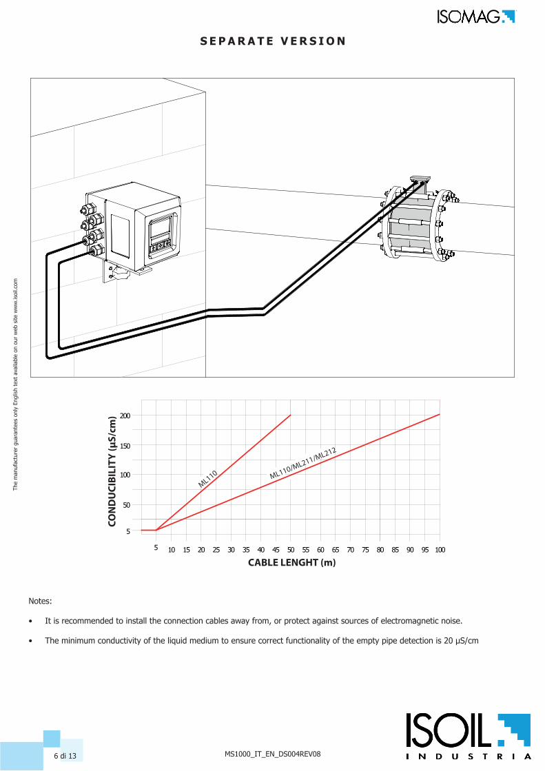
S E P A R A T E V E R S I O N
50
100
150
200
5 15 25 3010 20 35 40 45 50 55 60 65 70 75 80 85 90 95 100
5
ML110 ML1
10/ML211
/ML212
CABLE LENGHT (m)
CON
DU
CIBI
LITY
(µS/
cm)
Notes:
• It is recommended to install the connection cables away from, or protect against sources of electromagnetic noise. • The minimum conductivity of the liquid medium to ensure correct functionality of the empty pipe detection is 20 µS/cm

The
man
ufac
ture
r gu
aran
tees
onl
y En
glis
h te
xt a
vaila
ble
on o
ur w
eb s
ite w
ww
.isoi
l.com
MS1000_IT_EN_DS004REV087 di 13
LONG PIPEANTI VIBRATION JOINTS
3 X DN
2 X DN
2mm
2mm
Install the sensor away from bends and hydraulic accessories
Avoid positioning flanges by tigthening the nuts.
In vertical installations an ascending flow is preferable. For vertical installations with descending flowdirection contact the manufacturer
For installations in long pipe lines, please use anti vibration joints
Avoid a partially empty pipe, during operation the pipe must be either completely full of liquid or completelyempty
I N S T A L L A T I O N R E C O M M E N D A T I O N S
LONG PIPEANTI VIBRATION JOINTS
3 X DN
2 X DN
2mm
2mm
Install the sensor away from bends and hydraulic accessories
Avoid positioning flanges by tigthening the nuts.
In vertical installations an ascending flow is preferable. For vertical installations with descending flowdirection contact the manufacturer
For installations in long pipe lines, please use anti vibration joints
Avoid a partially empty pipe, during operation the pipe must be either completely full of liquid or completelyempty

The
man
ufac
ture
r gu
aran
tees
onl
y En
glis
h te
xt a
vaila
ble
on o
ur w
eb s
ite w
ww
.isoi
l.com
MS1000_IT_EN_DS004REV088 di 13
CENTERING CYLINDERS
Sensors weighing more than 20Kg are equipped of appropriate eyebolts to lift the sensor according to the drawing above.
The eyebolts support ONLY the weight of the meter.
R E C O M M E N D E D I N S T A L L A T I O N P R O C E D U R E

The
man
ufac
ture
r gu
aran
tees
onl
y En
glis
h te
xt a
vaila
ble
on o
ur w
eb s
ite w
ww
.isoi
l.com
MS1000_IT_EN_DS004REV089 di 13
SEALING GASKET
METALLIC PIPE
INSULATED PIPE
METALLIC RINGS
PIPE WITH CATHODIC PROTECTION
METALLIC RINGS
INSULATING BUSH
SEALING GASKET
If the sensor has to beinstalled in a pipe made of aninsulating material, thefollowing are neces-sary:
Inserting two metallic rings between the sensor flanges and the pipe line counter flanges
or:Using a sensor with the additional grounding electrode
If the sensor has to beinstalled in the pipe witha cathodic pro-tection,the following areneces-sary:
using insulating bushesto isolate the bolts
Metallic grounding rings should be provided to ground the liquid using insulating gasket between the rings
S E N S O R G R O U N D I N G
The
man
ufac
ture
r gu
aran
tees
onl
y En
glis
h te
xt a
vaila
ble
on o
ur w
eb s
ite w
ww
.isoi
l.com
MS1000_IT_EN_DS004REV0810 di 13
D
8°8°
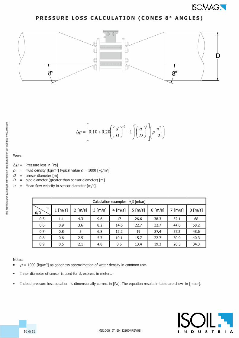
P R E S S U R E L O S S C A L C U L A T I O N ( C O N E S 8 ° A N G L E S )
−
+=D
−
2120.010.0
2422 uDd
Ddp r
Were:
Dp = Pressure loss in [Pa]r = Fluid density [kg/m3] typical value r= 1000 [kg/m3]d = sensor diameter [m]D = pipe diameter (greater than sensor diameter) [m]
u = Mean flow velocity in sensor diameter [m/s]
Calculation examples Dp [mbar]
u d/D
1 [m/s] 2 [m/s] 3 [m/s] 4 [m/s] 5 [m/s] 6 [m/s] 7 [m/s] 8 [m/s]
0.5 1.1 4.3 9.6 17 26.6 38.3 52.1 68
0.6 0.9 3.6 8.2 14.6 22.7 32.7 44.6 58.2
0.7 0.8 3 6.8 12.2 19 27.4 37.2 48.6
0.8 0.6 2.5 5.7 10.1 15.7 22.7 30.9 40.3
0.9 0.5 2.1 4.8 8.6 13.4 19.3 26.3 34.3
Notes: • r= 1000 [kg/m3] as goodness approximation of water density in common use.
• Inner diameter of sensor is used for d, express in meters.
• Indeed pressure loss equation is dimensionally correct in [Pa]. The equation results in table are show in [mbar].

The
man
ufac
ture
r gu
aran
tees
onl
y En
glis
h te
xt a
vaila
ble
on o
ur w
eb s
ite w
ww
.isoi
l.com
MS1000_IT_EN_DS004REV0811 di 13
MS 1000
codeT100
Nominal Diameter / Lining / Liquid temperature / Measuring range
P25 DN25 (PN16), Polypropilene lining Measuring range 0...0,72/0...18 m3/h
T25 DN25 (PN40), PTFE lining Measuring range 0...0,72/0...18 m3/h
P32 DN32 (PN16), Polypropilene lining Measuring range 0...1,16/0...29 m3/h
T32 DN32 (PN40), PTFE lining, Measuring range 0...1,16/0...29 m3/h
P40 DN40 (PN16), Polypropilene lining, liquid maximum temperature 60 °C Measuring range 0...1,8/0...45 m3/h
T40 DN40 (PN40), PTFE lining, liquid maximum temperature 150 °C Measuring range 0...1,8/0...45 m3/h
P50 DN50 (PN16), Polypropilene lining, liquid maximum temperature 60 °C Measuring range 0...2,88/0...72 m3/h
T50 DN50 (PN40), PTFE lining, liquid maximum temperature 150 °C Measuring range 0...2,88/0...72 m3/h
P65 DN65 (PN16), Polypropilene lining, liquid maximum temperature 60 °C Measuring range 0...4,8/0...120 m3/h
T65 DN65 (PN40), PTFE lining, liquid maximum temperature 150 °C Measuring range 0...4,8/0...120 m3/h
P80 DN80 (PN16), Polypropilene lining, liquid maximum temperature 60 °C Measuring range 0...7,2/0...180 m3/h
T80 DN80 (PN40), PTFE lining, liquid maximum temperature 150 °C Measuring range 0...7,2/0...180 m3/h
P100 DN100 (PN16), Polypropilene lining, liquid maximum temperature 60 °C Measuring range 0...11,2/0...280 m3/h
T100 DN100 (PN40), PTFE lining, liquid maximum temperature 150 °C Measuring range 0...11,2/0...280 m3/h
P125 DN125 (PN16), Polypropilene lining, liquid maximum temperature 60 °C Measuring range 0...18/0...450 m3/h
T125 DN125 (PN40), PTFE lining, liquid maximum temperature 150 °C Measuring range 0...18/0...450 m3/h
P150 DN150 (PN16), Polypropilene lining, liquid maximum temperature 60 °C Measuring range 0...25,6/0...640 m3/h
T150 DN150 (PN40), PTFE lining, liquid maximum temperature 150 °C Measuring range 0...25,6/0...640 m3/h
E200 DN200 (PN16), Ebanite lining, liquid maximum temperature 80 °C Measuring range 0…45,2/0…1130 m3/h
E250 DN250 (PN16), Ebanite lining, liquid maximum temperature 80 °C Measuring range 0…70,8 / 0…1770 m3/h
E300 DN300 (PN16), Ebanite lining, liquid maximum temperature 80 °C Measuring range 0…100,8 / 0…2520 m3/h
E350 DN350 (PN16), Ebanite lining, liquid maximum temperature 80 °C Measuring range 0…138 / 0…3450 m3/h
E400 DN400 (PN16),Ebanite lining, liquid maximum temperature 80 °C Measuring range 0…180 / 0…4500 m3/h
Gasket material ( internal tightness - only PP lining)
0
0 No O-Ring ( ONLY FOR PTFE/EBANITE LINING )
1 O-Ring : FKM
2 O-Ring : Epdm
9 Gasket material: to be specified
Body material
A
A Body in Carbon Steel painted
B Body in Stainless Steel (AISI304)
C Body in Stainless Steel (AISI316)
Z Body material: other
Number and electrodes material
2
2 n. 3 (2 measure + 1 for ground) electrodes in AISI316
4 n. 3 (2 measure + 1 for ground) electrodes in Hastelloy C
5 n. 3 (2 measure + 1 for ground) electrodes in Titanium
6 n. 3 (2 measure + 1 for ground) electrodes in Tantalum; not available with Polypropilene/Rilsan
7 n. 3 (2 measure + 1 for ground) electrodes in Platinum; not available with Polypropilene/Rilsan
0 Electrode material: to be specified
Version / Protection rate
H O W T O O R D E R

The
man
ufac
ture
r gu
aran
tees
onl
y En
glis
h te
xt a
vaila
ble
on o
ur w
eb s
ite w
ww
.isoi
l.com
MS1000_IT_EN_DS004REV0812 di 13
A
A Compact version , IP67 protection rate
B Separate version, Painted Aluminum JB, protection rate IP68, standing immersion with 1,5 m of head water - (DEFINE THE CABLE LENGHT - ADD THE COST )
G Separate version, Painted Aluminum JB, N° 1 connectors IP 68 suitable for fast cable connections - (DEFINE THE CABLE LENGHT - ADD THE COST )
F Separate version, Painted Aluminum JB, N° 2 connectors IP 68 suitable for fast cable connections - (DEFINE THE CABLE LENGHT - ADD THE COST )
N Separate version, Painted Aluminum JB , PREAMPLIFIRE*, protection rate IP67 - (DEFINE THE CABLE LENGHT MAX 500 m-ADD THE COST )
Q Separate version, Painted Aluminum JB, PREAMPLIFIRE*, N° 1 connectors IP 68 suitable for fast cable connection - (DEFINE THE CABLE LENGHT MAX 500 m-ADD THE COST )
U Separate version, AISI 304 JB RAW, protection rate IP68, standing immersion with 1,5 m of head water - (DEFINE THE CABLE LENGHT - ADD THE COST )
S Separate version, AISI 304 JB RAW, with N° 1 connectors IP 68 suitable for fast cable connections - (DEFINE THE CABLE LENGHT - ADD THE COST )
T Separate version, AISI 304 JB RAW, N° 2 connectors IP 68 suitable for fast cable connections - (DEFINE THE CABLE LENGHT - ADD THE COST )
P Separate version, AISI 304 JB RAW, PREAMPLIFIRE*, protection rate IP67 - (DEFINE THE CABLE LENGHT MAX 500 m-ADD THE COST )
R Separate version, AISI 304 JB RAW, PREAMPLIFIRE* N° 1 connectors IP 68 suitable for fast cable connections to - (DEFINE THE CABLE LENGHT MAX 500 m-ADD THE COST )
K Separate version, AISI 304 JB POLISCHED, protection rate IP68, standing immersion with 1,5 m of head water - (DEFINE THE CABLE LENGHT - ADD THE COST )
Y Separate version, AISI 304 JB POLISCHED, with N° 1 connectors IP 68 suitable for fast cable connections - (DEFINE THE CABLE LENGHT - ADD THE COST )
W Separate version, AISI 304 JB POLISCHED, N° 2 connectors IP 68 suitable for fast cable connections - (DEFINE THE CABLE LENGHT - ADD THE COST )
V Separate version, AISI 304 JB POLISCHED, PREAMPLIFIRE*, protection rate IP67 - (DEFINE THE CABLE LENGHT MAX 500 m-ADD THE COST )
J Separate version, AISI 304 JB POLISCHED, PREAMPLIFIRE* N° 1 connectors IP 68 suitable for fast cable connections to - (DEFINE THE CABLE LENGHT MAX 500 m-ADD THE COST )
MS1000-T100-0A2A (Example of Complete code for order)

ISOIL INDUSTRIA S.p.A.HEAD OFFICE SERVICE
Via Fratelli Gracchi, 2720092 Cinisello Balsamo (MI)Tel +39 02 66027.1Fax +39 02 [email protected]
If you want to find the complete list of our distributors access at the following link:http://www.isoil.com/u_vendita.asp
BEFORE returning any material, please contact our SERVICE at the e-mail adress:
Due to the constant technical development and improvement of its products, the manufacturer reserves the right to make changes and/or modify the information
contained in this document without notice.
AZIENDA CON SISTEMA DI GESTIONE QUALITA’
CERTIFICATO DA DNV GL
If you want to find the complete list of our distributors access at the following link:http://www.isoil.com/u_vendita.asp


![Angle Seat Globe Valve, Metal · 550 3 Kv values [m³/h] DN 6 DN 8 DN 10 DN 15 DN 20 DN 25 DN 32 DN 40 DN 50 DN 65 DN 80 Butt weld spigots, DIN 11850 1.6 1.8 2.4 2.4 - - - - - - -](https://img.pdfslide.net/doc/110x75/5f9509c77c6fed50eb12dcff/angle-seat-globe-valve-metal-550-3-kv-values-mh-dn-6-dn-8-dn-10-dn-15-dn-20.jpg)