Embed Size (px)
Citation preview

Data Sheet SS/S265-EN_04
S265 Remote seals with capillary tube
2600T Series Pressure Transmitters Engineered solutions for all applications
Wide range of remote seal types — Allows optimum design for each application without
compromising performance Large selection of options, materials and fill fluids — Meets nearly all process requirements
Designed for use with the 2600T pressure transmitter — Combines an economically feasible and technically sound
solution that ensures total reliability from line pressure to full vacuum
Special designed remote seals for individual process solutions — Added flexibility for the most demanding processes
Contents

2600T Series Pressure Transmitter S265 SS/S265-EN_04 Remote seals with capillary tube
2
Contents 1 Remote Seals Overview......................................................................................................................................3
1.1 Seal system selection criteria.........................................................................................................................3 1.2 Ordering information.......................................................................................................................................4 1.3 Fill fluid properties (Table A) ..........................................................................................................................4
2 S265W Model Wafer Remote Seal......................................................................................................................5 2.1 Mounting examples ........................................................................................................................................5 2.2 Seal dimensions .............................................................................................................................................6 2.3 Technical data ................................................................................................................................................8 2.4 Temperature effect .........................................................................................................................................8 2.5 Ordering information.......................................................................................................................................9 2.6 Ordering information (continued) .................................................................................................................10
3 S265F Model Flanged Flush and Extended Diaphragm Remote Seal..........................................................11 3.1 Seal dimensions ...........................................................................................................................................11 3.2 Technical data ..............................................................................................................................................13 3.3 Temperature effect .......................................................................................................................................13 3.4 Ordering information.....................................................................................................................................14 3.5 Ordering information (continued) .................................................................................................................15
4 S265M model off-line flanged connection remote seal .................................................................................16 4.1 Seal dimensions ...........................................................................................................................................16 4.2 Technical data ..............................................................................................................................................17 4.3 Temperature effect .......................................................................................................................................17 4.4 Ordering information.....................................................................................................................................18
5 S265J Model Inline Remote Seal (without flanges)........................................................................................19 5.1 Seal dimensions ...........................................................................................................................................19 5.2 Technical data ..............................................................................................................................................20 5.3 Temperature effect .......................................................................................................................................20 5.4 Ordering information.....................................................................................................................................21
Data Sheet 2600T Series Pressure Transmitter
S265
Remote seals with capillary tube

2600T Series Pressure Transmitter S265 SS/S265-EN_04 Remote seals with capillary tube
3
Approvals
1 Remote Seals Overview Change from one to two columns
The S265 seals are used in combination with 2600T transmitters for differential, gauge and absolute pressure measurements. Differential transmitters can be combined with one or two remote seals: • Two seals when using the same fill fluid, capillary tube length and
diaphragm material and size. • One seal, if the other side is equipped with a process flange. Transmitters for gauge and absolute pressure always have one remote seal. The S26 Series Seal System is a protective device used to isolate 2600T series transmitters from the process fluid. The seal system provides a flexible diaphragm between the process fluid and a liquid filled capillary tube connected to the body of the transmitter. The diaphragm isolates the process fluid while the filled capillary tube hydraulically transmits the process pressure to the transmitter sensor. The remote seal capillary is corrosion-resistant with robust construction in stainless steel with spiral armor protection, and an optional PVC jacket.
For certain applications, it is necessary to use a remote seal in order to suit specific process conditions, e.g.: • The process fluid has solids in suspension or is highly viscous
and can foul impulse lines. • The process fluid can solidify in impulse lines or the transmitter. • The transmitter must be located in a separate area from a
hazardous process fluid. • The process temperature exceeds the recommended limits for
the transmitter. • For interface level and density measurements. • The transmitter must be located in a separate area from the
process for easier maintenance. The S26 series is available with process connections for ASME or DIN pipe flanges. Extended diaphragm remote seals, suitable for connection to 2-, 3- or 4-inch resp. DN 50, DN 80 or DN 100 flanged tank nozzles or flanged tees, permit the seal diaphragm to be located flush with the inside of a tank or pipe. FDA approved fillings and compliance with 3-A Sanitary Standards are also available. Fill fluids with FDA approval are defined as food fills and are Generally Recognized As Safe (GRAS) by the US Food and Drug Administration (FDA).
Change from one to two columns
A
1.1 Seal system selection criteria Change from one to two columns
The application of an S26 system in direct mount or remote seal configuration to 2600T transmitters affects performance of the original device. These effects are shown in: • Accuracy • Temperature effect • Dynamic response Accuracy Accuracy is only marginally affected when seal diaphragm stiffness is relevant low compared with sensor stiffness. High stiffness of diaphragm associated with low URL might produce increased errors of linearity, hysteresis and long-term stability and has effect to the behavior of changing process- and environment conditions. Physically, the stiffness of the diaphragm is defined as the ratio of change in pressure to the corresponding volume displaced. Stiffness is not linear over the maximum permissible operating range of the diaphragm. For this reason, S26 seals are designed to ensure that only the linear range is used with the relevant sensor, if the transmitter is operated in the following limits. • Measuring range • Static pressure • Ambient and process temperature The stiffness of the diaphragm is a function of material & thickness (elastic coefficient), diameter (type), convolution shape and geometry (design defined). Temperature effect The S26 system has an effect on temperature performance of the complete transmitter. Errors primarily affect the zero position of units. They are caused by a temperature-dependent change in volume of the fill fluids in the seal system. The change in volume must be absorbed by the seal diaphragm. Depending on the stiffness of the diaphragm, additional pressure may form in the fill fluid, resulting in a zero error. The level of error depends on the stiffness of the seal diaphragm and the thermal expansion coefficient of the fill fluid.
Dynamic response Application of S26 seal to transmitters increases the original time response. The amount of the increase depends on the number of elements and condition of the instrument as follows: • Transmitter sensor range • Number of remote seals • Fill fluid viscosity of the S26 system applied • Ambient and process temperature • Capillary length The delay introduced by the seal may be added to the time constant of the associated transmitter. To obtain the best application solution: • Choose the sensor code with URL closest to the application
SPAN. • Select largest diameter diaphragm seal related to URL. • Keep the capillary length as short as possible • Use fluids with as low as possible viscosity and minimal thermal
expansion • In vacuum applications, mount the transmitter primary 30 cm / 12
inches or more below the lower seal connection. • When mounting two remote seals, use the identical size, capillary
tube length and fill fluid for both seals.
Change from one to two columns

2600T Series Pressure Transmitter S265 SS/S265-EN_04 Remote seals with capillary tube
4
1.2 Ordering information Change from one to two columns
The transmitter and each seal system are each identified by a product code number. The code numbers are listed on the type plate of the transmitter, and each character stands for a special product feature. Refer to ordering information for a detailed explanation of the product code numbers. A typical example of the product code is as follows: Transmitter product code: 265DRFSSA1AH-V1E1D3 Seal System Product Code: S265WHBCDFSBEH1
If remote seal applications not described in this data sheet are required, custom applications are available. Please allow ABB to check the existing options in this case by providing the application as well as process and ambient temperature. The following table shows the types of standard seals described in this data sheet. ABB can also work with you to develop a special remote seal for applications requiring individual solutions. Please contact your local ABB office or representative for additional information.
Change from one to two columns
A
1.3 Fill fluid properties (Table A)
Pressure in kPa abs
Fill fluids (applications) Id
Density at 20 °C in kg/m³
Thermal expansion (x10-4/K)
Process temperature 20 °C
(68 °F) 100 °C
(212 °F)150 °C
(302 °F) 200 °C
(392 °F) 250 °C
(482 °F)375 °C
(707 °F)Silicone oil IB 924 9.8 -30 … 250 °C
(-22 … 482 °F) > 50 > 50 > 50 > 75 > 100 -
Silicone oil IC 1055 8.1 -30 … 250 °C (-22 … 482 °F)
> 50 > 50 > 50 > 75 > 100 -
Carbon fluoride L 1860 11 -30 … 150 °C (-22 … 302 °F)
> 100 > 100 > 100 - - -
High temperature oil
SH 1070 7.7 -10 … 375 °C (14 … 707 °F)
> 50 > 50 > 50 > 75 > 100 > 100
White oil WB 849 7.9 -6 … 200 °C (21 … 392 °F)
> 50 > 100 > 100 > 100 > 100 -
Silicone oil for vacuum application
IC-V 1055 8.1 -30 … 200 °C (-22 … 392 °F)
> 0.5 > 2.5 > 3.8 > 5.0 - -
Important Seals with diaphragm made of Tantalum should not be used with temperatures more than 220°C. Seals dimensions on the following pages are in mm (inch).

2600T Series Pressure Transmitter S265 SS/S265-EN_04 Remote seals with capillary tube
5
2 S265W Model Wafer Remote Seal Change from one to two columns
The wafer remote seal is designed to be clamped between two ASME or DIN raised face flanges. The diaphragm side of the seal faces the process flange and a blind back-up flange is used on the other side of the seal.
Only gaskets manufactured from soft materials may be used with remote seals whose diaphragms and sealing surface is made of tantalum. Change from one to two columns
2.1 Mounting examples
Mounting examples and types of sealing surfaces for DN50 / DN80 or ASME 2 inch / 3 inch remote seals
Fig. 1
4 Blind flange 1 Form B2 acc. to EN 1092 (DIN 2526-E) Form RF (ASME B 16.5) 5 ASME application 2 Form E acc. to EN 1092 (DIN 2513 - V13) 6 DIN application 3 Form D acc. to EN 1092 (DIN 2512 - N) 7 DIN application with groove 8 DIN application with tongue
2600T Series Pressure Transmitter S265 SS/S265-EN_04 Remote seals with capillary tube
6
A
2.2 Seal dimensions
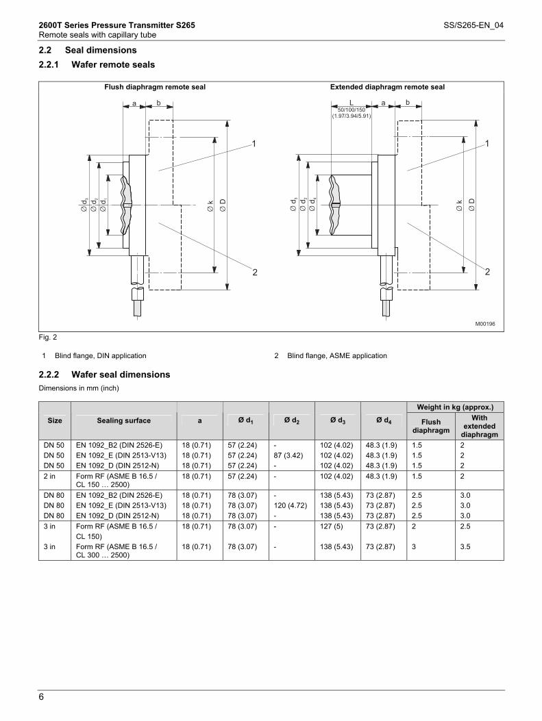
2.2.1 Wafer remote seals
Flush diaphragm remote seal Extended diaphragm remote seal
Fig. 2 1 Blind flange, DIN application 2 Blind flange, ASME application
2.2.2 Wafer seal dimensions
Dimensions in mm (inch)
Weight in kg (approx.) Size Sealing surface a Ø d1 Ø d2 Ø d3 Ø d4 Flush
diaphragm With
extended diaphragm
DN 50 DN 50 DN 50
EN 1092_B2 (DIN 2526-E) EN 1092_E (DIN 2513-V13) EN 1092_D (DIN 2512-N)
18 (0.71) 18 (0.71) 18 (0.71)
57 (2.24) 57 (2.24) 57 (2.24)
- 87 (3.42) -
102 (4.02) 102 (4.02) 102 (4.02)
48.3 (1.9) 48.3 (1.9) 48.3 (1.9)
1.5 1.5 1.5
2 2 2
2 in Form RF (ASME B 16.5 / CL 150 … 2500)
18 (0.71) 57 (2.24) - 102 (4.02) 48.3 (1.9) 1.5 2
DN 80 DN 80 DN 80
EN 1092_B2 (DIN 2526-E) EN 1092_E (DIN 2513-V13) EN 1092_D (DIN 2512-N)
18 (0.71) 18 (0.71) 18 (0.71)
78 (3.07) 78 (3.07) 78 (3.07)
- 120 (4.72) -
138 (5.43) 138 (5.43) 138 (5.43)
73 (2.87) 73 (2.87) 73 (2.87)
2.5 2.5 2.5
3.0 3.0 3.0
3 in 3 in
Form RF (ASME B 16.5 / CL 150) Form RF (ASME B 16.5 / CL 300 … 2500)
18 (0.71) 18 (0.71)
78 (3.07) 78 (3.07)
- -
127 (5) 138 (5.43)
73 (2.87) 73 (2.87)
2 3
2.5 3.5

2600T Series Pressure Transmitter S265 SS/S265-EN_04 Remote seals with capillary tube
7
2.2.3 Wafer connection dimensions, dimensions in mm (inch)
Information on flange design (not supplied) Screws required
Flange type Ø k Ø D Number Ø bore hole
b
DN 50 DN 50 DN 50
PN 16 / 40 PN 63 PN 100
125 (4.92) 135 (5.31) 145 (5.71)
165 (6.5) 180 (7.09) 195 (7.68)
4 4 4
18 (0.71) 22 (0.87) 26 (1.02)
18/20 (0.71/0.79) 26 (1.02) 28 (1.1)
2 in 2 in 2 in 2 in
150 psi 300 psi 600 psi 1500 psi
120.6 (4.75) 127 (5) 127 (5) 165.1 (6.5)
152.4 (6) 165.1 (6.5) 165.1 (6.5) 215.9 (8.5)
4 8 8 8
19.1 (0.75) 19.1 (0.75) 19.1 (0.75) 25.4 (1.00)
19 (0.75) 22.2 (0.87) 25.4 (1) 38.1 (1.5)
DN 80 DN 80 DN 80
PN 16 / 40 PN 63 PN 100
160 (6.3) 170 (6.69) 180 (7.09)
200 (7.87) 215 (8.46) 230 (9.06)
8 8 8
18 (0.71) 22 (0.87) 26 (1.02)
20/24 (0.79/0.94) 28 (1.1) 32 (1.26)
3 in 3 in 3 in 3 in
150 psi 300 psi 600 psi 1500 psi
152.4 (6) 168.3 (6.63) 168.3 (6.63) 203.3 (8)
190.5 (7.5) 209.5 (8.25) 209.5 (8.25) 266.7 (10.5)
4 8 8 8
19.1 (0.75) 22.4 (0.88) 22.4 (0.88) 31.8 (1.25)
23.8 (0.94) 28.6 (1.13) 31.8 (1.25) 47.6 (1.87)
Important Gasket and fixing accessories not supplied. Mounting with capillary tube.

2600T Series Pressure Transmitter S265 SS/S265-EN_04 Remote seals with capillary tube
8
Change from one to two columns
2.3 Technical data
Maximum Working Pressure Flush diaphragm wafer remote seals • Acc. to DIN from PN 10 bar to PN 400 bar • Acc. to ASME from 150 psi to 2500 psi Extended diaphragm remote seal • Acc. to DIN from PN 10 bar to PN 100 bar • Acc. to ASME from 150 psi to 600 psi but not higher than the load
capacity of the flange (not supplied) Vacuum Service Same as fill fluid limits. Refer to table A. Process Temperature Limits Same as fill fluid limits. Refer to table A. • 220 °C (428 °F) for tantalum diaphragm. • 150 °C (302 °F) for use with FEP anti-stick coating.
2.4 Temperature effect
The following table shows the temperature effect for a 20 K (36 °F) change, detailed separately for: a) the seal (one element) b) the capillary tube per meter c) the transmitter (in addition to the transmitter data sheet) when
filling IB silicone oil (for models 265Dx) or IC silicone oil (for models 265Gx/Ax) and stainless steel diaphragm materials.
When using a different filling than silicone oil, the errors can be multiplied by the quotient of thermal expansion coefficient of actual filling divided by the thermal expansion coefficient of silicone oil (filling X / silicone oil). (See table “Fill fluid properties”.)
Important The errors provided in the table can be divided by 4 when using the identical seal on both sides.
Change from one to two columns
S265W Wafer remote seal, connected to 265DR Additional effect for each 20 K (36 °F) temperature change
System (sensor) error Capillary error per meter Seal error Size kPa mbar in H2O kPa mbar in H2O kPa mbar in H2O
Flush diaphragm 2 in / DN 50 0.065 0.65 0.26 0.03 0.3 0.12 0.07 0.7 0.28 Flush diaphragm 3 in / DN 80 0.04 0.4 0.16 0.02 0.2 0.08 0.04 0.4 0.16 Extended diaphragm
2 in / DN 50 0.08 0.8 0.32 0.035 0.35 0.14 0.16 1.6 0.64
Extended diaphragm
3 in / DN 80 0.015 0.15 0.06 0.008 0.08 0.032 0.02 0.2 0.08
265W Wafer remote seal connected to 265GR/AR Additional effect for each 20 K (36 °F) temperature change
System (sensor) error Capillary error per meter Seal error Size kPa mbar in H2O kPa mbar in H2O kPa mbar in H2O
Flush diaphragm 2 in / DN 50 0.03 0.3 0.12 0.03 0.3 0.12 0.07 0.7 0.28 Flush diaphragm 3 in / DN 80 0.02 0.2 0.08 0.02 0.2 0.08 0.04 0.4 0.16 Extended diaphragm
2 in / DN 50 0.04 0.4 0.16 0.035 0.35 0.14 0.16 1.6 0.64
Extended diaphragm
3 in / DN 80 0.01 0.1 0.04 0.008 0.08 0.032 0.02 0.2 0.08

2600T Series Pressure Transmitter S265 SS/S265-EN_04 Remote seals with capillary tube
9
2.5 Ordering information
Wafer remote seal Variant digit No. 1 - 6 7 8 9 10 11 CodeS265W Catalog No. S265W-Transmitter side of connectionHigh side - bottom HLow side - bottom LSize Pressure rating, without ext. diaphr. Pressure rating, with ext. diaphr.2 in ASME CL 150 ... CL 2500 ASME CL 150 ... CL 600 B3 in ASME CL 150 ASME CL 150 N3 in ASME CL 300 ... CL 2500 ASME CL 300 ... CL 600 CDN 50 PN 10 ... PN 400 PN 10 ... PN 100 EDN 80 PN 10 ... PN 400 PN 10 ... PN 100 FSeat finish - DN 50 / 2 inForm RF - raised face (ASME B 16.5) 1) EEN 1092 - B2 (DIN 2526 - Form E) (PN 10 ... PN 400) 2) SEN 1092 - E (DIN 2513-V13) (PN 10 ... PN 100) 2) MEN 1092- D (DIN 2512-N) (PN 10 ... PN 160) 2) NSeat finish - DN 80 / 3 inForm RF - raised face (ASME B 16.5) 1) EEN 1092 - B2 (DIN 2526 - Form E) (PN 10 ... PN 400) 2) SEN 1092 - E (DIN 2513-V13) (PN 10 ... PN 100) 2) MEN 1092- D (DIN 2512-N) (PN 10 ... PN 160) 2) NExtensions length / Material - DN 50 / 2 inFlush F50 mm (2 in) AISI 316L ss 150 mm (2 in) Hastelloy C276 2100 mm (4 in) AISI 316L ss 3100 mm (4 in) Hastelloy C276 4150 mm (6 in) AISI 316L ss 5150 mm (6 in) Hastelloy C276 6Extensions length / Material - DN 80 / 3 inFlush F50 mm (2 in) AISI 316L ss 150 mm (2 in) Hastelloy C276 2100 mm (4 in) AISI 316L ss 3100 mm (4 in) Hastelloy C276 4150 mm (6 in) AISI 316L ss 5150 mm (6 in) Hastelloy C276 6Diaphragm material - DN 50 / 2 inAISI 316L ss NACE 3) SHastelloy C276 NACE 4) 6) HTantalum NACE 5) 6) TAISI 316L ss with FEP anti-stick coating NACE 5) 6) 1Hastelloy C276 with FEP anti-stick coating NACE 5) 6) 2Diaphragm material - DN 80 / 3 inAISI 316L ss NACE 3) SHastelloy C276 NACE 4) HTantalum NACE 5) 6) TAISI 316L ss with FEP anti-stick coating NACE 5) 6) 1Hastelloy C276 with FEP anti-stick coating NACE 5) 6) 2
1) Not available with Size code E, F Continued on next page2) Not available with Size code B, N, C3) Not available with Extensions length / Material code 2, 4, 64) Not available with Extensions length / Material code 1, 3, 55) Not available with Extensions length / Material code 1, 2, 3, 4, 5, 66) Not available with Seat finish code N

2600T Series Pressure Transmitter S265 SS/S265-EN_04 Remote seals with capillary tube
10
2.6 Ordering information (continued)
Wafer remote seal Variant digit No. 1 - 6 10 11 12 13 14 CodeS265W Catalog No. S265W-Capillary protectionAISI 316 ss armoured AAISI 316 ss armoured with PVC protective cover price per meter BCapillary length1 m (3 ft) A2 m (7 ft) C4 m (13 ft) G6 m (20 ft) L8 m (27 ft) Q11 m (37 ft) W16 m (53 ft) VSpecial length between 1 m and 16 m
basic price of the next longer standard length plus an extra fee ZFill FluidSilicone oil SCarbon fluoride 7) NSilicone oil for high temperature HWhite oil (FDA approved) 8) WSilicone oil for vacuum proof design L
7) Suitable for oxygen applications8) Suitable for food applications
Hastelloy is a trademark of Cabot CorporationMonel is a trademark of International Nickel Co.
2600T Series Pressure Transmitter S265 SS/S265-EN_04 Remote seals with capillary tube
11
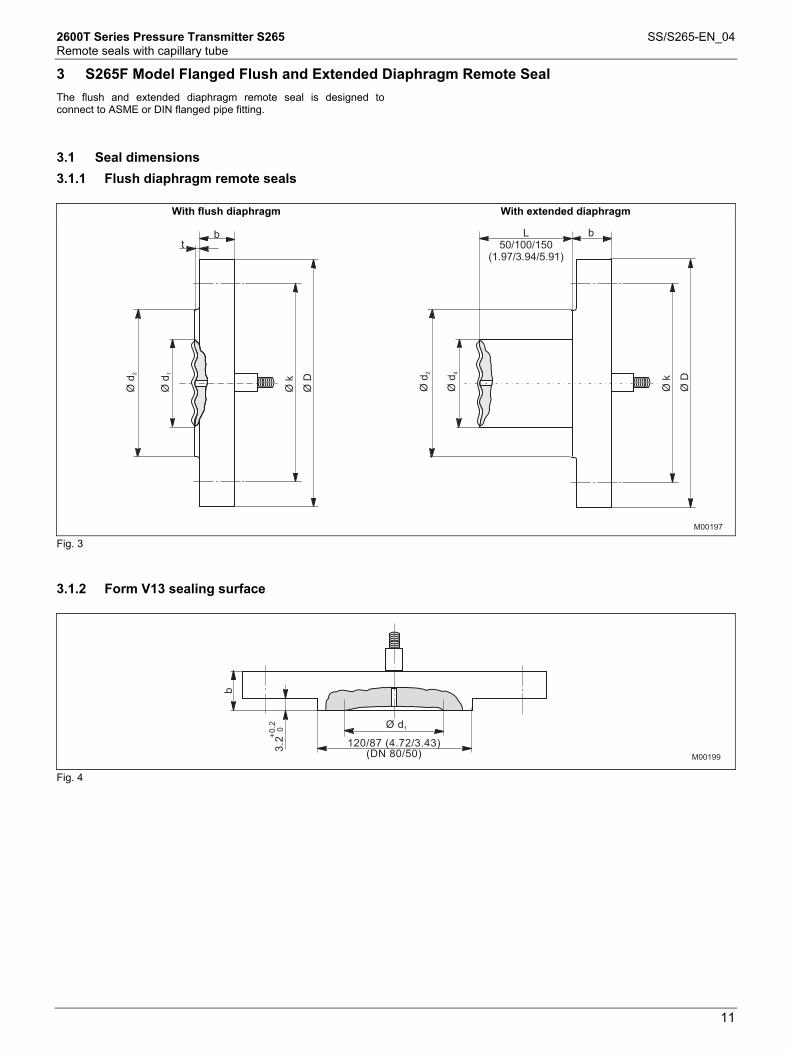
3 S265F Model Flanged Flush and Extended Diaphragm Remote Seal Change from one to two columns
The flush and extended diaphragm remote seal is designed to connect to ASME or DIN flanged pipe fitting.
Change from one to two columns
A
3.1 Seal dimensions
3.1.1 Flush diaphragm remote seals
With flush diaphragm With extended diaphragm
b
ØD
Øk
Ød
2
Ød
4
L
50/100/150
(1.97/3.94/5.91)
t
b
ØD
Øk
Ød
2
Ød
1
M00197 Fig. 3 3.1.2 Form V13 sealing surface
3.2
Ø d1
120/87 (4.72/3.43)
(DN 80/50)
b
+0
.2
0
M00199
Fig. 4

2600T Series Pressure Transmitter S265 SS/S265-EN_04 Remote seals with capillary tube
12
3.1.3 Sealing surface
Form RF (ASME B 16.5), EN 1092-B2 (DIN 2526-E), EN 1092-D (DIN 2512-N) Measurements in mm/inches
Size Pressure rating Ø D Ø k Extension
Ø d4 Ø d1 Ø d2
DN 50 DN 50 DN 50
PN 16 / 40 PN 63 PN 100
165 (6.50) 180 (7.09) 195 (7.68)
125 (4.92) 135 (5.31) 145(5.71)
48,3 (1.9) 48,3 (1.9) 48,3 (1.9)
57 (2.24) 57 (2.24) 57 (2.24)
102 (4.02) 102 (4.02) 102 (4.02)
DN 80 DN 80 DN 80
PN 16 / 40 PN 63 PN 100
200 (7.87) 215 (8.46) 230 (9.06)
160 (6.30) 170 (6.69) 180 (7.09)
73 (2.87) 73 (2.87) 73 (2.87)
75 (2.95) 75 (2.95) 75 (2.95)
138 (5.43) 138 (5.43) 138 (5.43)
DN 100 PN 16 220 (8.66) 210 (8.27 94 (3.70) 89 (3.50) 1) 188 (7.40) 2 in 2 in 2 in
Class 150 Class 300 Class 600
152.4 (6.00) 165.1 (6.50) 165.1 (6.50)
120.6 (4.75) 127 (5.00) 127 (5.00)
48,3 (1.9) 48,3 (1.9) 48,3 (1.9)
57 (2.24) 57 (2.24) 57 (2.24)
92.1 (3.63) 92.1 (3.63) 92.1 (3.63)
3 in 3 in 3 in
Class 150 Class 300 Class 600
190.5 (7.50) 209.5 (8.25) 209.5 (8.25)
152.4 (6.00) 168.3 (6.63) 168.3 (6.63)
73 (2.87) 73 (2.87) 73 (2.87)
75 (2.95) 75 (2.95) 75 (2.95)
127 (5.00) 127 (5.00) 127 (5.00)
4 in Class 150 230 (9.06) 190.5 (7.50) 94 (3.70) 89 (3.50) 158 (6.22)
Screws required Weight in kg Size Pressure rating t b
Number Ø bore hole Flush diaphragm
With extended diaphragm
DN 50 DN 50 DN 50
PN 16 / 40 PN 63 PN 100
2 (0.08) 2 (0.08) 2 (0.08)
20 (0.79) 26 (1.02) 28 (1.10)
4 4 4
18 (0.71) 22 (0.87) 26 (1.02)
3,3 4,5 5,8
4 5,2 6,5
DN 80 DN 80 DN 80
PN 16 / 40 PN 63 PN 100
2 (0.08) 2 (0.08) 2 (0.08)
24 (0.94) 28 (1.10) 32 (1.26)
8 8 8
18 (0.71) 22 (0.87) 26 (1.02)
5,8 6,9 9,4
7,5 8,6 11,1
DN 100 PN 16 2 (0.08) 22 (0.87) 8 18 (0.71) 5,9 6,8 2 in 2 in 2 in
Class 150 Class 300 Class 600
1.6 (0.06) 1.6 (0.06) 6.35 (0.25)
19,1 (0.75) 22,4 (0.88) 25,4 (1.0)
4 8 8
19.1 (0.75) 19.1 (0.75) 19.1 (0.75)
2,3 3,7 4,5
4 5,4 6,2
3 in 3 in 3 in
Class 150 Class 300 Class 600
1.6 (0.06) 1.6 (0.06) 6.35 (0.25)
22,2 (0.87) 28,4 (1.12) 31,8 (1.25)
4 8 8
19.1 (0.75) 22.4 (0.88) 22.4 (0.88)
5,3 7,3 9,1
7 9 10,8
4 in Class 150 1.6 (0.06) 24 (0.94) 8 19.1 (0.75) 7,7 8,6 1) not available for form V13 sealing surface
2600T Series Pressure Transmitter S265 SS/S265-EN_04 Remote seals with capillary tube
13
Change from one to two columns
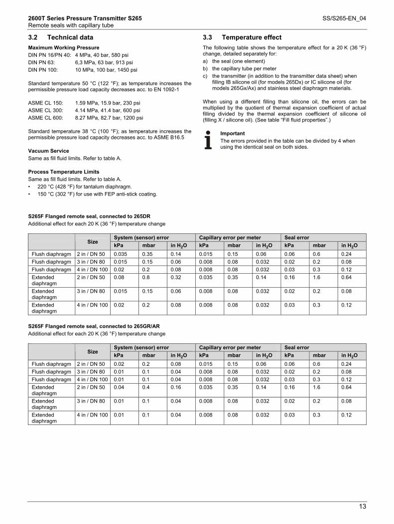
3.2 Technical data
Maximum Working Pressure DIN PN 16/PN 40: 4 MPa, 40 bar, 580 psi DIN PN 63: 6,3 MPa, 63 bar, 913 psi DIN PN 100: 10 MPa, 100 bar, 1450 psi Standard temperature 50 °C (122 °F); as temperature increases the permissible pressure load capacity decreases acc. to EN 1092-1 ASME CL 150: 1.59 MPa, 15.9 bar, 230 psi ASME CL 300: 4.14 MPa, 41.4 bar, 600 psi ASME CL 600: 8.27 MPa, 82.7 bar, 1200 psi Standard temperature 38 °C (100 °F); as temperature increases the permissible pressure load capacity decreases acc. to ASME B16.5 Vacuum Service Same as fill fluid limits. Refer to table A. Process Temperature Limits Same as fill fluid limits. Refer to table A. • 220 °C (428 °F) for tantalum diaphragm. • 150 °C (302 °F) for use with FEP anti-stick coating.
3.3 Temperature effect
The following table shows the temperature effect for a 20 K (36 °F) change, detailed separately for: a) the seal (one element) b) the capillary tube per meter c) the transmitter (in addition to the transmitter data sheet) when
filling IB silicone oil (for models 265Dx) or IC silicone oil (for models 265Gx/Ax) and stainless steel diaphragm materials.
When using a different filling than silicone oil, the errors can be multiplied by the quotient of thermal expansion coefficient of actual filling divided by the thermal expansion coefficient of silicone oil (filling X / silicone oil). (See table “Fill fluid properties”.)
Important The errors provided in the table can be divided by 4 when using the identical seal on both sides.
Change from one to two columns
S265F Flanged remote seal, connected to 265DR Additional effect for each 20 K (36 °F) temperature change
System (sensor) error Capillary error per meter Seal error Size kPa mbar in H2O kPa mbar in H2O kPa mbar in H2O
Flush diaphragm 2 in / DN 50 0.035 0.35 0.14 0.015 0.15 0.06 0.06 0.6 0.24 Flush diaphragm 3 in / DN 80 0.015 0.15 0.06 0.008 0.08 0.032 0.02 0.2 0.08 Flush diaphragm 4 in / DN 100 0.02 0.2 0.08 0.008 0.08 0.032 0.03 0.3 0.12 Extended diaphragm
2 in / DN 50 0.08 0.8 0.32 0.035 0.35 0.14 0.16 1.6 0.64
Extended diaphragm
3 in / DN 80 0.015 0.15 0.06 0.008 0.08 0.032 0.02 0.2 0.08
Extended diaphragm
4 in / DN 100 0.02 0.2 0.08 0.008 0.08 0.032 0.03 0.3 0.12
S265F Flanged remote seal, connected to 265GR/AR Additional effect for each 20 K (36 °F) temperature change
System (sensor) error Capillary error per meter Seal error Size kPa mbar in H2O kPa mbar in H2O kPa mbar in H2O
Flush diaphragm 2 in / DN 50 0.02 0.2 0.08 0.015 0.15 0.06 0.06 0.6 0.24 Flush diaphragm 3 in / DN 80 0.01 0.1 0.04 0.008 0.08 0.032 0.02 0.2 0.08 Flush diaphragm 4 in / DN 100 0.01 0.1 0.04 0.008 0.08 0.032 0.03 0.3 0.12 Extended diaphragm
2 in / DN 50 0.04 0.4 0.16 0.035 0.35 0.14 0.16 1.6 0.64
Extended diaphragm
3 in / DN 80 0.01 0.1 0.04 0.008 0.08 0.032 0.02 0.2 0.08
Extended diaphragm
4 in / DN 100 0.01 0.1 0.04 0.008 0.08 0.032 0.03 0.3 0.12
2600T Series Pressure Transmitter S265 SS/S265-EN_04 Remote seals with capillary tube
14
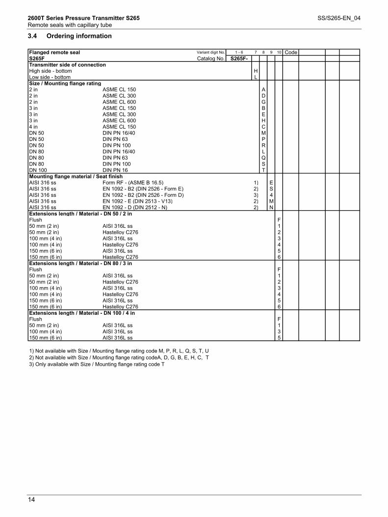
3.4 Ordering information
Flanged remote seal Variant digit No. 1 - 6 7 8 9 10 CodeS265F Catalog No. S265F-Transmitter side of connectionHigh side - bottom HLow side - bottom LSize / Mounting flange rating2 in ASME CL 150 A2 in ASME CL 300 D2 in ASME CL 600 G3 in ASME CL 150 B3 in ASME CL 300 E3 in ASME CL 600 H4 in ASME CL 150 CDN 50 DIN PN 16/40 MDN 50 DIN PN 63 PDN 50 DIN PN 100 RDN 80 DIN PN 16/40 LDN 80 DIN PN 63 QDN 80 DIN PN 100 SDN 100 DIN PN 16 TMounting flange material / Seat finishAISI 316 ss Form RF - (ASME B 16.5) 1) EAISI 316 ss EN 1092 - B2 (DIN 2526 - Form E) 2) SAISI 316 ss EN 1092 - B2 (DIN 2526 - Form D) 3) 4AISI 316 ss EN 1092 - E (DIN 2513 - V13) 2) MAISI 316 ss EN 1092 - D (DIN 2512 - N) 2) NExtensions length / Material - DN 50 / 2 inFlush F50 mm (2 in) AISI 316L ss 150 mm (2 in) Hastelloy C276 2100 mm (4 in) AISI 316L ss 3100 mm (4 in) Hastelloy C276 4150 mm (6 in) AISI 316L ss 5150 mm (6 in) Hastelloy C276 6Extensions length / Material - DN 80 / 3 inFlush F50 mm (2 in) AISI 316L ss 150 mm (2 in) Hastelloy C276 2100 mm (4 in) AISI 316L ss 3100 mm (4 in) Hastelloy C276 4150 mm (6 in) AISI 316L ss 5150 mm (6 in) Hastelloy C276 6Extensions length / Material - DN 100 / 4 inFlush F50 mm (2 in) AISI 316L ss 1100 mm (4 in) AISI 316L ss 3150 mm (6 in) AISI 316L ss 5
1) Not available with Size / Mounting flange rating code M, P, R, L, Q, S, T, U2) Not available with Size / Mounting flange rating codeA, D, G, B, E, H, C, T3) Only available with Size / Mounting flange rating code T

2600T Series Pressure Transmitter S265 SS/S265-EN_04 Remote seals with capillary tube
15
3.5 Ordering information (continued)
Flanged remote seal Variant digit No. 1 - 6 11 12 13 14 CodeS265F Catalog No. S265F-Diaphragm material - Form RF / EN 1092-B2 (DIN 2526-Form E)AISI 316L ss NACE 4) SHastelloy C276 NACE 5) HTantalum NACE 6) 7) TAISI 316L ss with FEP anti-stick coating NACE 6) 7) 1Hastelloy C276 with FEP anti-stick coating NACE 6) 7) 2Diaphragm material - EN 1092 - E (DIN 2513-V13)AISI 316L ss NACE 4) SHastelloy C276 NACE 5) HTantalum NACE 6) 7) TAISI 316L ss with FEP anti-stick coating NACE 6) 7) 1Hastelloy C276 with FEP anti-stick coating NACE 6) 7) 2Diaphragm material - EN 1092 - D (DIN 2512-N)AISI 316L ss NACE 4) SHastelloy C276 NACE 5) HCapillary protectionAISI 316 ss armoured AAISI 316 ss armoured with PVC protective cover price per meter BCapillary length1 m (3 ft) A2 m (7 ft) C4 m (13 ft) G6 m (20 ft) L8 m (27 ft) Q11 m (37 ft) W16 m (53 ft) VSpecial length between 1 m and 16 m
basic price of the next longer standard length plus an extra fee ZFill FluidSilicone oil SCarbon fluoride 8) NSilicone oil for high temperature HWhite oil (FDA approved) 9) WSilicone oil for vacuum proof design L
4) Not available with Extensions length / Material code 2, 4, 65) Not available with Extensions length / Material code 1, 3, 56) Not available with Extensions length / Material code 1, 2, 3, 4, 5, 67) Not available with Mounting flange material / Seat finish code N8) Suitable for oxygen applications9) Suitable for food applications
Hastelloy is a trademark of Cabot Corporation
2600T Series Pressure Transmitter S265 SS/S265-EN_04 Remote seals with capillary tube
16
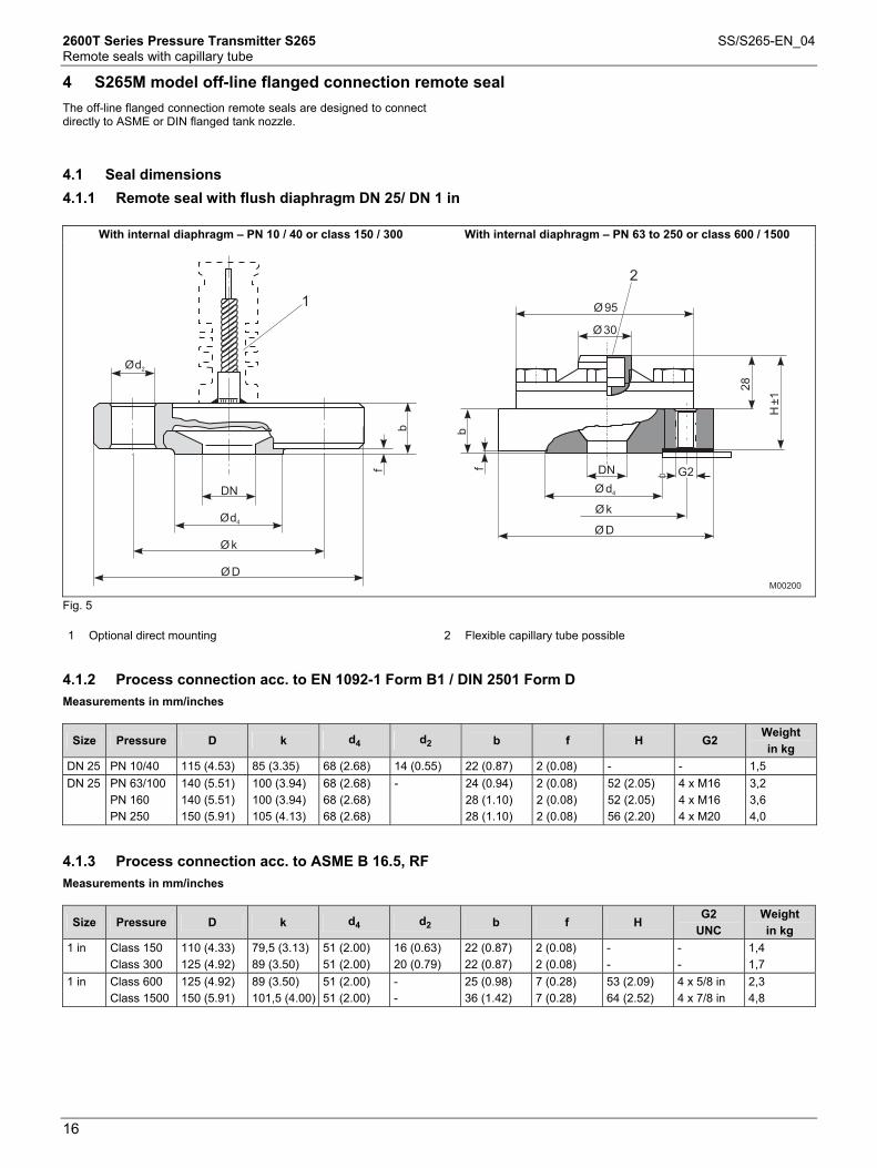
4 S265M model off-line flanged connection remote seal Change from one to two columns
The off-line flanged connection remote seals are designed to connect directly to ASME or DIN flanged tank nozzle.
Change from one to two columns
A
4.1 Seal dimensions
4.1.1 Remote seal with flush diaphragm DN 25/ DN 1 in
With internal diaphragm – PN 10 / 40 or class 150 / 300 With internal diaphragm – PN 63 to 250 or class 600 / 1500
1
2
DN
Øk
ØD
Ø2
d
Ø4
d
b
f
b
f
28
H±1
DN
Ød4
G2
Øk
ØD
Ø30
Ø95
M00200 Fig. 5 1 Optional direct mounting 2 Flexible capillary tube possible
4.1.2 Process connection acc. to EN 1092-1 Form B1 / DIN 2501 Form D
Measurements in mm/inches
Size Pressure D k d4 d2 b f H G2 Weight in kg
DN 25 PN 10/40 115 (4.53) 85 (3.35) 68 (2.68) 14 (0.55) 22 (0.87) 2 (0.08) - - 1,5 DN 25 PN 63/100
PN 160 PN 250
140 (5.51) 140 (5.51) 150 (5.91)
100 (3.94) 100 (3.94) 105 (4.13)
68 (2.68) 68 (2.68) 68 (2.68)
- 24 (0.94) 28 (1.10) 28 (1.10)
2 (0.08) 2 (0.08) 2 (0.08)
52 (2.05) 52 (2.05) 56 (2.20)
4 x M16 4 x M16 4 x M20
3,2 3,6 4,0
4.1.3 Process connection acc. to ASME B 16.5, RF
Measurements in mm/inches
Size Pressure D k d4 d2 b f H G2
UNC Weight in kg
1 in Class 150 Class 300
110 (4.33) 125 (4.92)
79,5 (3.13) 89 (3.50)
51 (2.00) 51 (2.00)
16 (0.63) 20 (0.79)
22 (0.87) 22 (0.87)
2 (0.08) 2 (0.08)
- -
- -
1,4 1,7
1 in Class 600 Class 1500
125 (4.92) 150 (5.91)
89 (3.50) 101,5 (4.00)
51 (2.00) 51 (2.00)
- -
25 (0.98) 36 (1.42)
7 (0.28) 7 (0.28)
53 (2.09) 64 (2.52)
4 x 5/8 in 4 x 7/8 in
2,3 4,8

2600T Series Pressure Transmitter S265 SS/S265-EN_04 Remote seals with capillary tube
17
Change from one to two columns
4.2 Technical data
Maximum Working Pressure DIN PN 10/PN 40: 4 MPa, 40 bar, 580 psi DIN PN 63/PN 100: 10 MPa, 100 bar, 1450 psi DIN PN 160: 16 MPa, 160 bar, 2320 psi DIN PN 250: 25 MPa, 250 bar, 3625 psi Standard temperature 50 °C (122 °F); as temperature increases the permissible pressure load capacity decreases acc. to EN 1092-1 ASME CL 150: 1.59 MPa, 15.9 bar, 230 psi ASME CL 300: 4.14 MPa, 41.4 bar, 600 psi ASME CL 600: 8.27 MPa, 82.7 bar, 1200 psi ASME CL 1500: 20.68 MPa, 206.8 bar, 3000 psi Standard temperature 38 °C (100 °F); as temperature increases the permissible pressure load capacity decreases acc. to ASME B16.5 Vacuum Service Same as fill fluid limits. Refer to table A. Process Temperature Limits Same as fill fluid limits. Refer to table A. Same as fill fluid limits but not greater than 250 °C (482 °F)
4.3 Temperature effect
The following table shows the temperature effect for a 20 K (36 °F) change, detailed separately for: a) the seal (one element) b) the capillary tube per meter c) the transmitter (in addition to the transmitter data sheet) when
filling IC silicone oil (for models 265Gx/Ax) and stainless steel diaphragm materials.
Change from one to two columns
S265M off-line remote seal, connected to 265GR/AR Additional effect for each 20 K (36 °F) temperature change
System (sensor) error Capillary error per meter Seal error Size
kPa mbar in H2O kPa mbar in H2O kPa mbar in H2O 1 in / DN 25 0.025 0.25 0.1 0.025 0.25 0.1 0.06 0.6 0.24

2600T Series Pressure Transmitter S265 SS/S265-EN_04 Remote seals with capillary tube
18
4.4 Ordering information
Mini-flanged remote seal Variant digit No. 1 - 6 7 8 9 10 11 12 13 CodeS265M Catalog No. S265M-Transmitter side of connectionHigh side - bottom HSize / Mounting flange rating1 in ASME CL 150 A1 in ASME CL 300 C1 in ASME CL 600 E1 in ASME CL 1500 KDN 25 DIN PN 10/40 HDN 25 DIN PN 63/100 LDN 25 DIN PN 160 TDN 25 DIN PN 250 VMounting flange material / Seat finishAISI 316 ss Form RF - raised face (ASME B 16.5) NACE 1) EAISI 316 ss EN 1092 - B1 (DIN 2526 - Form D) NACE 2) 4AISI 316 ss EN 1092 - D (DIN 2512 - N) NACE 3) NDiaphragm materialAISI 316L ss NACE SCapillary protectionAISI 316 ss armoured AAISI 316 ss armoured with PVC protective cover price per meter BCapillary length1 m (3 ft) A2 m (7 ft) C4 m (13 ft) G6 m (20 ft) LSpecial length between 1 m and 6 m
basic price of the next longer standard length plus an extra fee ZFill FluidSilicone oil SSilicone oil for vacuum proof design L
1) Not available with Size / Mounting flange rating code H, L, T, V2) Not available with Size / Mounting flange rating code A, C, E, K3) Not available with Size / Mounting flange rating code A, C, E, K, L, T, V

2600T Series Pressure Transmitter S265 SS/S265-EN_04 Remote seals with capillary tube
19
5 S265J Model Inline Remote Seal (without flanges) A
5.1 Seal dimensions
5.1.1 Inline Remote Seal (without flanges)
L
H
D
ØMb
M00201
12
Fig. 6 1 Flexible capillary tube possible 2 Wrench size, SW 27
5.1.2 Process connection acc. to EN 1092-1 / ASME B 16.5
Measurements in mm/inches
Size Pressure D L Mb Weight in kg
1 in / DN 25 PN 6 to PN 100 150 psi to 2500 psi
63 (2.48) 60 (2.36) 28,5 (1.12) 1,4
1 ½ in / DN 40 PN 6 to PN 100 300 psi to 2500 psi
85 (3.35) 60 (2.36) 43 (1.69) 2,2
2 in / DN 50 PN 6 to PN 100 150 psi to 2500 psi
95 (3.74) 60 (2.36) 54,5 (2.15) 2,5
3 in / DN 80 PN 6 to PN 100 150 psi to 2500 psi
130 (5.12) 60 (2.36) 82,5 (3.25) 4,0

2600T Series Pressure Transmitter S265 SS/S265-EN_04 Remote seals with capillary tube
20
Change from one to two columns
5.2 Technical data
Maximum Working Pressure DIN-compliant from PN 6 bar to PN 100 bar (higher pressure stages on request), ASME-compliant from 150 (300) psi to 2500 psi, but not higher than the rating of the mounting flange (not supplied). Vacuum Service Same as fill fluid limits. Refer to table A. Process Temperature Limits Same as fill fluid limits. Refer to table A.
5.3 Temperature effect
The following table shows the temperature effect for a 20 K (36 °F) change, detailed separately for: a) the seal (one element) b) the capillary tube per meter c) the transmitter (in addition to the transmitter data sheet) when
filling IC silicone oil (for models 265Gx/Ax) and stainless steel diaphragm materials.
When using a different filling than silicone oil, the errors can be multiplied by the quotient of thermal expansion coefficient of actual filling divided by the thermal expansion coefficient of silicone oil (filling X / silicone oil). (See table “Fill fluid properties”.)
Change from one to two columns
S265J inline remote seal (without flanges), connected to 265GR/AR Additional effect for each 20 K (36 °F) temperature change
System (sensor) error Capillary error per meter Seal error Size
kPa mbar in H2O kPa mbar in H2O kPa mbar in H2O 1 in / DN 25 1 10 4 0.8 8 3.2 2 20 8 1 ½ in / DN 40 0.6 6 2.4 0.6 6 2.4 1.2 12 4.8 2 in / DN 50 0.15 1.5 0.6 0.15 1.5 0.6 0.4 4 1.6 3 in / DN 80 0.25 2.5 1 0.25 2.5 1 0.6 6 2.4

2600T Series Pressure Transmitter S265 SS/S265-EN_04 Remote seals with capillary tube
21
5.4 Ordering information
In-line Remote Seal Variant digit No. 1 - 6 7 8 9 10 11 12 CodeS265J Catalog No. S265J-Transmitter side of connectionHigh side - bottom HSizeDN 25 / ASME 1 in ADN 40 / ASME 1-1/2 in BDN 50 / ASME 2 in CDN 80 / ASME 3 in DDiaphragm material - DN 25 / ASME 1 inAISI 316L ss NACE RHastelloy C276 NACE DDiaphragm material - DN 40 / ASME 1-1/2 inAISI 316L ss NACE RHastelloy C276 NACE DDiaphragm material - DN 50 / ASME 2 inAISI 316L ss NACE RHastelloy C276 NACE DDiaphragm material - DN 80 / ASME 3 inAISI 316L ss NACE RHastelloy C276 NACE DCapillary protectionAISI 316 ss armoured AAISI 316 ss armoured with PVC protective cover price per meter BCapillary length1 m (3 ft) A2 m (7 ft) C4 m (13 ft) G6 m (20 ft) L8 m (27 ft) Q11 m (37 ft) W16 m (53 ft) VSpecial length between 1 m and 16 m
basic price of the next longer standard length plus an extra fee ZFill FluidSilicone oil SCarbon fluoride 1) NSilicone oil for high temperature HWhite oil (FDA approved) 2) WSilicone oil for vacuum proof design L
1) Suitable for oxygen applications2) Suitable for food applications


Contact us
SS
/S26
5-EN
0412
.201
0|
3KXP
6000
02R
1001ABB Ltd.
Process Automation Howard Road, St. Neots Cambridgeshire, PE19 8EU UK Phone: +44 (0)1480 475321 Fax: +44 (0)1480 217948 ABB Inc. Process Automation 125 E. County Line Road Warminster PA 18974 USA Phone: +1 215 674 6000 Fax: +1 215 674 7183 ABB Automation Products GmbH Process Automation Schillerstr. 72 32425 Minden Germany Phone: +49 551 905-534 Fax: +49 551 905-555 www.abb.com
Note We reserve the right to make technical changes or modify the contents of this document without prior notice. With regard to purchase orders, the agreed particulars shall prevail. ABB does not accept any responsibility whatsoever for potential errors or possible lack of information in this document. We reserve all rights in this document and in the subject matter and illustrations contained therein. Any reproduction, disclosure to third parties or utilization of its contents in whole or in parts – is forbidden without prior written consent of ABB. Copyright© 2010 ABB All rights reserved