Embed Size (px)
Citation preview
C4ISR / tactical communications connectors and cables
Data, signal, and power connectivity solutions
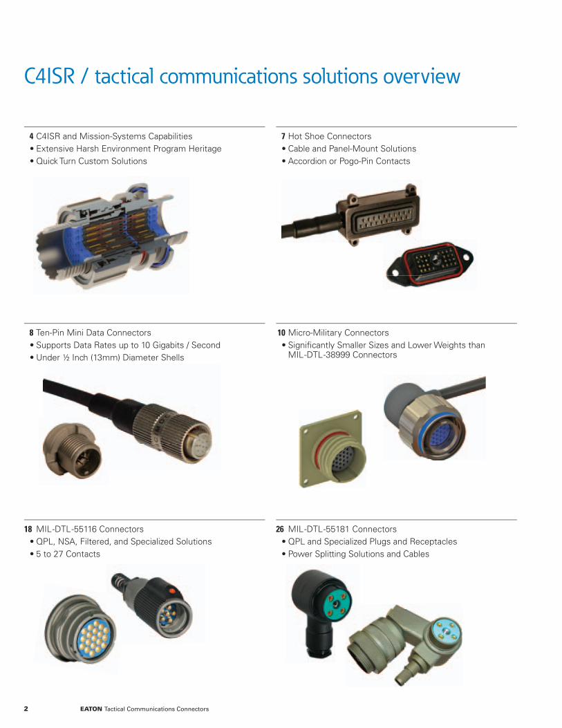
C4ISR / tactical communications solutions overview
4 C4ISR and Mission-Systems Capabilities • Extensive Harsh Environment Program Heritage • Quick Turn Custom Solutions
7 Hot Shoe Connectors • Cable and Panel-Mount Solutions • Accordion or Pogo-Pin Contacts
8 Ten-Pin Mini Data Connectors • Supports Data Rates up to 10 Gigabits / Second • Under ½ Inch (13mm) Diameter Shells
10 Micro-Military Connectors • Signifi cantly Smaller Sizes and Lower Weights than MIL--DTL--38999 Connectors
18 MIL--DTL--55116 Connectors • QPL, NSA, Filtered, and Specialized Solutions • 5 to 27 Contacts
26 MIL--DTL--55181 Connectors • QPL and Specialized Plugs and Receptacles • Power Splitting Solutions and Cables
2 EATON Tactical Communications Connectors
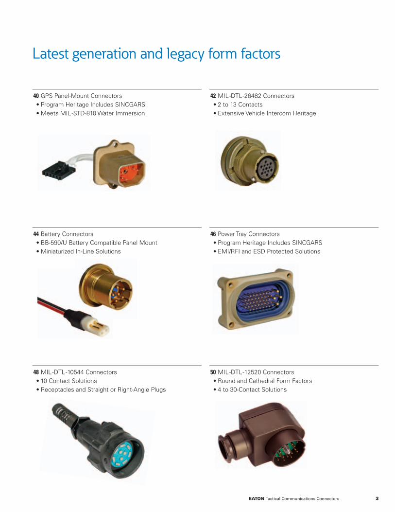
Latest generation and legacy form factors
40 GPS Panel-Mount Connectors • Program Heritage Includes SINCGARS • Meets MIL--STD-810 Water Immersion
42 MIL--DTL--26482 Connectors • 2 to 13 Contacts • Extensive Vehicle Intercom Heritage
44 Battery Connectors • BB-590/U Battery Compatible Panel Mount • Miniaturized In-Line Solutions
46 Power Tray Connectors • Program Heritage Includes SINCGARS • EMI/RFI and ESD Protected Solutions
48 MIL--DTL--10544 Connectors • 10 Contact Solutions • Receptacles and Straight or Right-Angle Plugs
50 MIL--DTL--12520 Connectors • Round and Cathedral Form Factors • 4 to 30-Contact Solutions
3EATON Tactical Communications Connectors

C4ISR and mission systems solutions
Heritage proven products and
custom capabilities position Eaton
as a primary source for C4ISR and
mission systems interconnect for
all physical domains: air, space,
sea, and terrestrial.
Eaton has the product breadth and demonstrated fi eld-proven performance needed to support a broad range of C4ISR and mission-system applications. QPL and specialized standard products and modifi ed/custom solution capabilities include: • Form factors ranging from latest generation miniaturized to legacy.
• High-current power, high-speed data, and fi ltered signal solutions.
• Operation in extreme EMI/RFI, temperatures, shock/vibration, radiation, corrosive media, and vacuum/pressures.
• Custom connectors, cable assemblies, wiring harnesses, and non-explosive actuators.
4 EATON Tactical Communications Connectors
From subsea to space; Eaton’s program heritage includes custom connector/cable assemblies for submarine weapons control (left) and MIL-DTL-38999 NATC, space-rated (right) applications.
MIL-DTL-38999 Series III and IV solutions support applications ranging from battlefi eld-weapons control to airborne-weapons release.
Mission-system-connectivity heritage includes shoulder fi red guided missiles and shipboard vertical launch missiles.
Naval interconnect heritage includes sonar arrays, minesweepers, propulsion control, ROVs, and weapons control.
C4ISR and mission systems program heritage
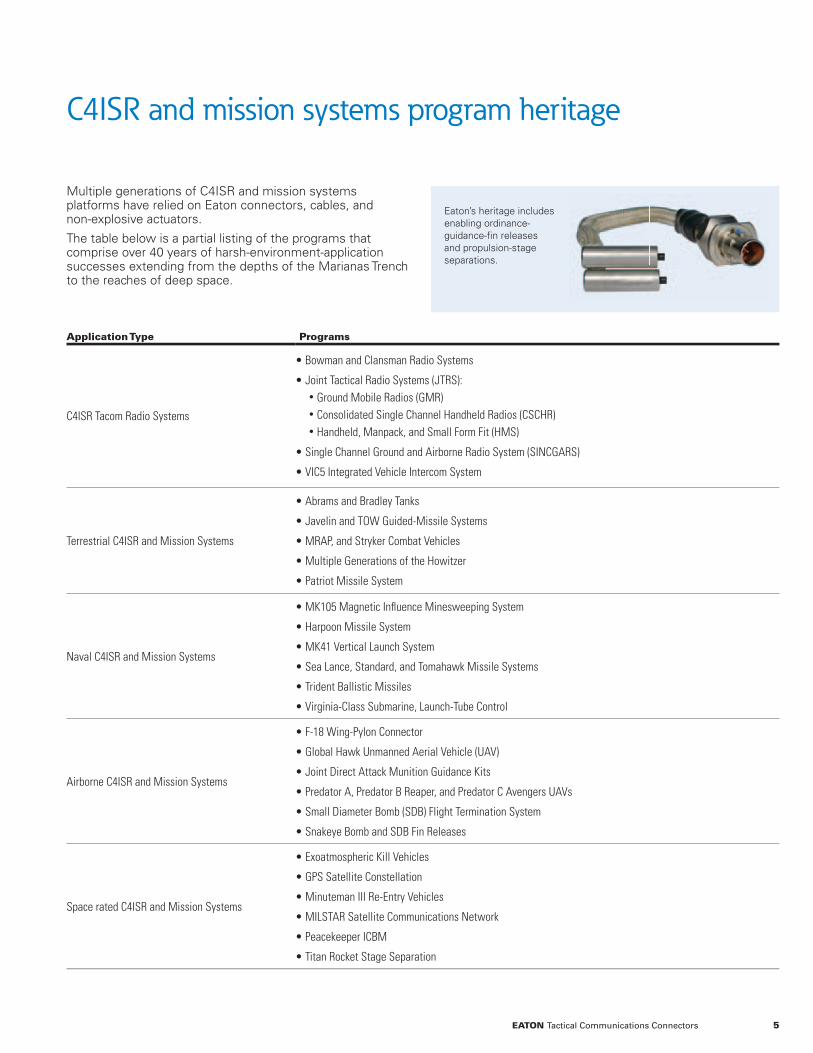
Multiple generations of C4ISR and mission systems platforms have relied on Eaton connectors, cables, and non-explosive actuators.
The table below is a partial listing of the programs that comprise over 40 years of harsh-environment-application successes extending from the depths of the Marianas Trench to the reaches of deep space.
Application Type Programs
C4ISR Tacom Radio Systems
• Bowman and Clansman Radio Systems
• Joint Tactical Radio Systems (JTRS):• Ground Mobile Radios (GMR)• Consolidated Single Channel Handheld Radios (CSCHR)• Handheld, Manpack, and Small Form Fit (HMS)
• Single Channel Ground and Airborne Radio System (SINCGARS)
• VIC5 Integrated Vehicle Intercom System
Terrestrial C4ISR and Mission Systems
• Abrams and Bradley Tanks
• Javelin and TOW Guided-Missile Systems
• MRAP, and Stryker Combat Vehicles
• Multiple Generations of the Howitzer
• Patriot Missile System
Naval C4ISR and Mission Systems
• MK105 Magnetic Infl uence Minesweeping System
• Harpoon Missile System
• MK41 Vertical Launch System
• Sea Lance, Standard, and Tomahawk Missile Systems
• Trident Ballistic Missiles
• Virginia-Class Submarine, Launch-Tube Control
Airborne C4ISR and Mission Systems
• F-18 Wing-Pylon Connector
• Global Hawk Unmanned Aerial Vehicle (UAV)
• Joint Direct Attack Munition Guidance Kits
• Predator A, Predator B Reaper, and Predator C Avengers UAVs
• Small Diameter Bomb (SDB) Flight Termination System
• Snakeye Bomb and SDB Fin Releases
Space rated C4ISR and Mission Systems
• Exoatmospheric Kill Vehicles
• GPS Satellite Constellation
• Minuteman III Re-Entry Vehicles
• MILSTAR Satellite Communications Network
• Peacekeeper ICBM
• Titan Rocket Stage Separation
5EATON Tactical Communications Connectors
Eaton’s heritage includes enabling ordinance-guidance-fi n releases and propulsion-stage separations.

Heritage proven custom capabilities
Eaton combines advanced
engineering tools with an
extensive array of manufacturing
resources to quickly deliver
custom solutions.Harsh environment, custom capabilities include connectors for cryogenic fuel and coolant monitoring.
3D modeling software is integrated with CAM resources to concurrently manufacture parts for prototype solutions including inserts, which can be machined or molded as needed to meet schedule requirements. An extensive array of in-house environmental test equipment, including thermal-vacuum chambers, also ac-celerates prototype development.
Technology portfolio
An extensive portfolio of fi eld-proven products and technologies satisfi es a signifi cant number of customer requirements with only minor modifi cations.
Extensive experience
Eaton has an in-depth understanding of the materials, mechanisms, and electronic design required for harsh environment, mission-critical applications.
Modeling and simulation
Our design teams utilize SolidWorks to simulate a complete array of harsh-environment mechanical and thermal stresses.
Defi ned toll-gate process
New product development is controlled through a defi ned toll-gate process to ensure consistent, predictable, and successful results.
Mission critical engineering resources
6 EATON Tactical Communications Connectors

Hotshoe connectors
Eaton utilizes standardized designs and production processes to facilitate quick-turn development of custom hotshoe-connector solutions. Design options include: • Accordion or pogo pin style contacts. • Single or redundant contacts for each position with pointed, 2D cupped, or radiused-tip geometries.
• Tail confi gurations include through hole, SMT, vertical mating, and right-angle mating.
• Custom connector/cable assemblies. Please contact Eaton to discuss hotshoe connectors tailored to your specifi c application requirements.
Scrubbing action of accordion-style contacts provides reliable connections even after exposure to moisture
Flat-pin designs facilitate high-contact-density solutions
Environmental protections include internal moisture sealing
End-to-end connectivity solutions include custom cable assemblies and wiring harnesses
360° EMI/RFI shielding
7EATON Tactical Communications Connectors
Accordion-Spring Contacts Compared To Traditional Designs
ElectricalLarger Contact Surface Areas Reduce Impedance
Improved Contact Resistance Stability
Mechanical
Single-Piece Design Eliminates the Possibility of Contaminant Build Up Between Contact Parts
Mechanical Properties are Maintained over an Exponentially Higher Number of Engagement Cycles

Miniaturized ten-pin connectors
Eaton’s miniaturized 10-pin connectors deliver high-speed data capabilities in form factors that are approximately one-half-inch in diameter. Additional features of these ultra-compact solutions include: • Supports data rates up to 10 gigabits per second. • EMI/RFI protection includes shielded cables and receptacle case-grounding pins.
• 1.4 amps per contact current rating. • Rugged designs survive 2000 engagement cycles.
General Specifi cations
Materials and Finishes
Receptacle and Plug Shells Passivated Stainless SteelPanel Nuts Passivated Stainless SteelContacts Phosphor Bronze/Gold over NickelInserts Nylon Type 6/6 (Zytel 101)Cable Shield Ferrule Brass/NickelCable Overmold Material Black Santoprene
Electrical
Dielectric Strength 500 VRMSInsulation Resistance 1000 Megaohms Minimum at 500VDCCurrent Rating per Contact 1.4 AmpsCable Construction 10 Conductor, 28AWG Shielded Cable
MechanicalEnvironmental Sealing 15 PSIWater Immersion One MeterMate/Unmate Durability 2000 Cycles
EMI/RFI protection includes cable shielding
and receptacle shell ground pins
Supports data rates up to 10 Gb/s
Passivated stainless-steel shells
Cable assembly options include application specifi c
lengths and terminations
8 EATON Tactical Communications Connectors

Length as per part number LLL designator
Over Mold10 conductor, 28 AWG shielded cable
2.0”(50.80mm)
0.50”(12.70mm)
0.38”(9.65mm)
Flats
0.55”(13.97mm)
Ø0.56”(Ø14.22mm)
0.15”(3.81mm)
0.09”(2.29mm)
0.12”(3.05mm)Max. Panel Thickness
0.15”(3.81mm)Typ.Ø0.65”
(Ø16.51mm)Jam Nut
Miniaturized ten-pin data connectors
Plug/cable assembly ordering information Mates with receptacle part number CIMP1-10P-1
CIMDC1 - 10S - LLL
Prefix for Miniaturized Data-Cable Assembly
Plug/Cable Assembly Length in Centimeters as per Drawing Below
10 = Number of Contacts, S = Sockets
Solder-pin terminations include case ground.
CIMP1-10P-1 Receptacle
CIMDC1-10S plug
9EATON Tactical Communications Connectors
Micro-military circular connectors
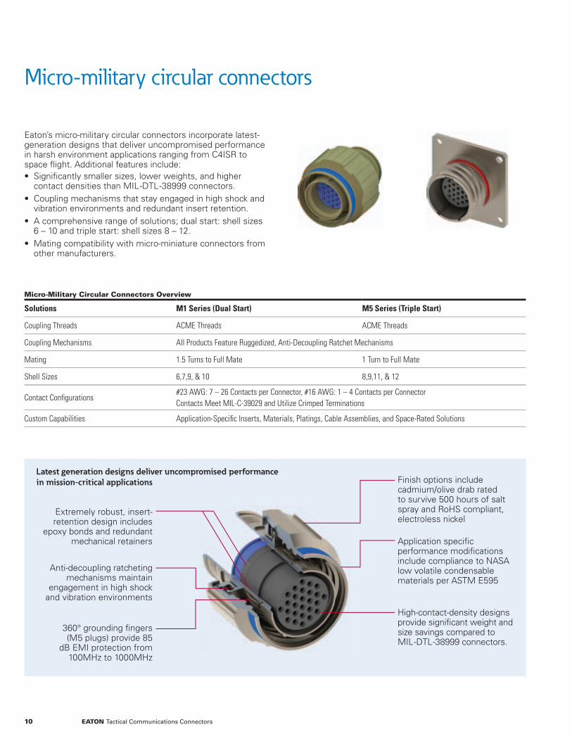
Eaton’s micro-military circular connectors incorporate latest-generation designs that deliver uncompromised performance in harsh environment applications ranging from C4ISR to space fl ight. Additional features include: • Signifi cantly smaller sizes, lower weights, and higher contact densities than MIL--DTL--38999 connectors.
• Coupling mechanisms that stay engaged in high shock and vibration environments and redundant insert retention.
• A comprehensive range of solutions; dual start: shell sizes 6 – 10 and triple start: shell sizes 8 – 12.
• Mating compatibility with micro-miniature connectors from other manufacturers.
Extremely robust, insert-retention design includes
epoxy bonds and redundant mechanical retainers
Latest generation designs deliver uncompromised performance in mission-critical applications
Anti-decoupling ratcheting mechanisms maintain
engagement in high shock and vibration environments
360° grounding fi ngers (M5 plugs) provide 85
dB EMI protection from 100MHz to 1000MHz
High-contact-density designs provide signifi cant weight and size savings compared to MIL--DTL--38999 connectors.
Finish options include cadmium/olive drab rated to survive 500 hours of salt spray and RoHS compliant, electroless nickel
Application specifi c performance modifi cations include compliance to NASA low volatile condensable materials per ASTM E595
Micro-Military Circular Connectors Overview
Solutions M1 Series (Dual Start) M5 Series (Triple Start)
Coupling Threads ACME Threads ACME Threads
Coupling Mechanisms All Products Feature Ruggedized, Anti-Decoupling Ratchet Mechanisms
Mating 1.5 Turns to Full Mate 1 Turn to Full Mate
Shell Sizes 6,7,9, & 10 8,9,11, & 12
Contact Confi gurations#23 AWG: 7 – 26 Contacts per Connector, #16 AWG: 1 – 4 Contacts per ConnectorContacts Meet MIL-C-39029 and Utilize Crimped Terminations
Custom Capabilities Application-Specifi c Inserts, Materials, Platings, Cable Assemblies, and Space-Rated Solutions
10 EATON Tactical Communications Connectors

General Specifications
Materials and Finishes
Shell and Coupling Ring 6061 Aluminum
Contacts Copper Alloy, Gold Plated
Inserts LPS (Liquid Crystal Polymer) 30% Glass Filled
Grommet and Seal Fluorosilicone
Contact Retaining Springs Beryllium Copper
Electrical
Dielectric Withstand Voltage (DWV)23 AWG Contact Inserts: 500 VAC 16 AWG Contact Inserts: 1800 VAC
Insulation Resistance (IR) 5000 Megaohms Minimum
Contact Current Ratings #23 Contacts – 5 Amps, #16 Contacts – 13 Amps
EMI/RFI ShieldingM1 Series: 55 dB Minimum from 100MHz to 1000MHz M5 Series: 85 dB Minimum from 100MHz to 1000MHz
Mechanical andEnvironmental
Contact Retention #23 Contacts: 15 pounds, #16 Contacts: 25 pounds
Shock and Vibration 300 g’s Shock, 37 g’s Random Vibration
Insert Retention Epoxy Bonds and Redundant Mechanical Retainers
Water Immersion MIL-STD-810, Method 512, One Meter Immersion for One Hour
Mate/Unmate Durability M1 Series: 2000 Cycles, M5 Series: 500 Cycles
Finish Classes
Class F Class W
Plating Type Electroless Nickel Cadmium/Olive Drab
Compliances ASTM B733 & RoHS QQ-P-416
Operating Temperatures -65°C to 200°C (-85°F to 392°F) -65°C to 175°C (-85°F to 347°F)
Corrosion Resistance Withstands 48 Hours Salt Spray Withstands 500 Hours Salt Spray
Shell-to-Shell Conductivity 1.0 Millivolt Maximum Drop 2.5 Millivolts Maximum Drop
Micro-military circular connectors
11EATON Tactical Communications Connectors
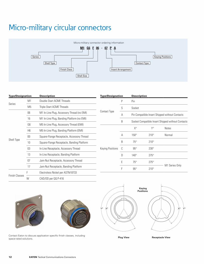
Micro-military connector ordering information
M1 G6 F 06 - 07 P A
Series
Shell Type
Finish Class
Shell Size
Keying Positions
Contact Type
Insert Arrangement
Type/Designation Description
SeriesM1 Double Start ACME Threads
M5 Triple Start ACME Threads
Shell Type
06 M1 In-Line Plug, Accessory Thread (no EMI)
16 M1 In-Line Plug, Banding Platform (no EMI)
G6 M5 In-Line Plug, Accessory Thread (EMI)
H6 M5 In-Line Plug, Banding Platform (EMI)
00 Square-Flange Receptacle, Accessory Thread
10 Square-Flange Receptacle, Banding Platform
03 In-Line Receptacle, Accessory Thread
13 In-Line Receptacle, Banding Platform
07 Jam-Nut Receptacle, Accessory Thread
17 Jam-Nut Receptacle, Banding Platform
Finish ClassesF Electroless Nickel per ASTM B733
W CAD/OD per QQ P-416
Type/Designation Description
Contact Type
P Pin
S Socket
A Pin Compatible Insert Shipped without Contacts
B Socket Compatible Insert Shipped without Contacts
Keying Positions
X° Y° Notes
A 150° 210° Normal
B 75° 210°
C 95° 230°
D 140° 275°
E 75° 275°M1 Series Only
F 95° 210°
Contact Eaton to discuss application specific finish classes, including space-rated solutions. Plug View Receptacle View
KeyingPositions
X° Y° X° Y°
Micro-military circular connectors
12 EATON Tactical Communications Connectors

23AWG ContactInsert Arrangements
1 2
36
5 4
7
3 1
10
7 4
8
2
9
1234
8
13171819
16
12
7
1 236
11151823
25 26 2421
16129
4
M1 Series Shell - Insert # 06-07 07-10 09-19 10-26
M5 Series Shell - Insert # 08-07 09-10 11-19 12-26
Number of Contacts 7 10 19 26
Current Rating per Contact 5 Amps 5 Amps 5 Amps 5 Amps
16AWG ContactInsert Arrangements
1 2
4 3
M1 Series Shell - Insert # 06-01 09-04
M5 Series Shell - Insert # 08-01 11-04
Number of Contacts 1 4
Current Rating per Contact 13 Amps 13 Amps
Contact Eaton to discuss quick turn, application specific contacts and insert arrangements.
End-to-End Connectivity Solutions Include Custom Cable Assemblies
Cable assembly and wiring harness design and manufacturing capabilities include: overmolded; RF coaxial; flat ribbon; fiber optic; and voice, data, and hybrid communications.
Our engineers are experts at providing protection against harsh-environmental conditions including: • Extreme high and low temperatures • Shock and vibration • Radiation • Corrosive contaminants • EMI and RFI • Vacuum and pressures to 20,000 PSI
In addition to turnkey design and manufacturing for new projects, quick-turn capabilities include shielded; build-to-print services for production-ready designs.
Micro-military circular connectors
13EATON Tactical Communications Connectors
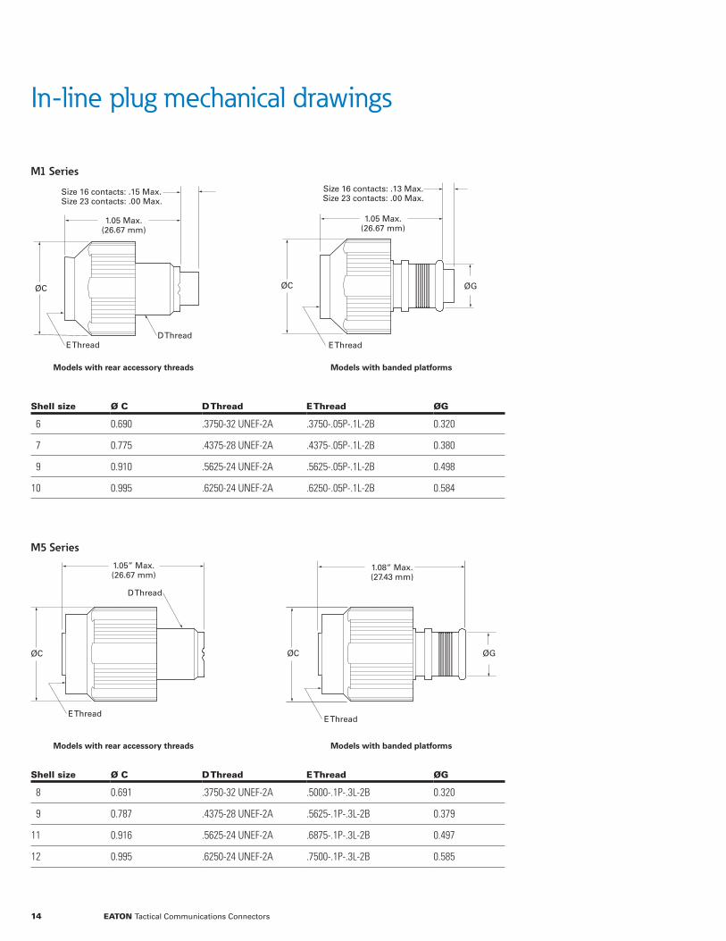
In-line plug mechanical drawings
M1 Series
M5 Series
Models with banded platforms
Size 16 contacts: .13 Max.Size 23 contacts: .00 Max.
1.05 Max.(26.67 mm)
ØG ØC
E Thread
Models with accessory threads
1.05 Max.(26.67 mm)
D Thread
Size 16 contacts: .15 Max.Size 23 contacts: .00 Max.
ØC
E Thread
1.08” Max.(27.43 mm)
ØG ØC
E Thread
1.05” Max.(26.67 mm)
D Thread
E Thread
ØC
Models with accessory threads
Shell size Ø C D Thread E Thread ØG
6 0.690 .3750-32 UNEF-2A .3750-.05P-.1L-2B 0.320
7 0.775 .4375-28 UNEF-2A .4375-.05P-.1L-2B 0.380
9 0.910 .5625-24 UNEF-2A .5625-.05P-.1L-2B 0.498
10 0.995 .6250-24 UNEF-2A .6250-.05P-.1L-2B 0.584
Shell size Ø C D Thread E Thread ØG
8 0.691 .3750-32 UNEF-2A .5000-.1P-.3L-2B 0.320
9 0.787 .4375-28 UNEF-2A .5625-.1P-.3L-2B 0.379
11 0.916 .5625-24 UNEF-2A .6875-.1P-.3L-2B 0.497
12 0.995 .6250-24 UNEF-2A .7500-.1P-.3L-2B 0.585
Models with rear accessory threads
Models with rear accessory threads
Models with banded platforms
Models with banded platforms
14 EATON Tactical Communications Connectors

Jam-nut receptacle mechanical drawings
M1 Series
M5 Series
0.99” Max.(25.15 mm)
0.44” Max.(11.18 mm)
0.06” Max.(1.52 mm)
E Thread
G Thread
Models with banded platforms
A Max. Flat
A Max. Flat
ØB Max.
Models with accessory threads
Size 16 contacts: 0.08” Max.Size 23 contacts: 0.00” Max.
0.93”(23.62 mm)
0.39” Max(9.91 mm)
0.06” Max(1.52 mm)
F Thread
G Thread
E Thread
1.17” Max.(29.72 mm)
0.75” Max.(19.05 mm)
E Thread
G Thread
Models with banded platforms
Size 16 contacts: 0.25 Max.Size 23 contacts: 0.00 Max.
A Max
A Max
ØB Max
Size 16 contacts: 0.03 Max.Size 23 contacts: 0.00 Max.
1.17” Max.(29.72 mm)
0.75” Max.(19.05 mm)
E ThreadG Thread
F Thread
Models with accessory threads
Shell size A B E Thread F Thread G Thread
8 0.755 0.785 .5000-.1P-.3L-2A .3750-32 UNEF-2A .5625-28 UN-2A
9 0.875 0.905 .5625-.1P-.3L-2A .4375-28 UNEF-2A .6875-28 UN-2A
11 0.950 0.980 .6875-.1P-.3L-2A .5625-24 UNEF-2A .7500-28 UN-2A
12 1.060 1.085 .7500-.1P-.3L-2A .6250-24 UNEF-2A .8125-28 UN-2A
Shell size A B E Thread F Thread G Thread
6 0.620 0.660 .3750-.05P-.1L-2B .3750-32 UNEF-2A .4375-28 UNEF-2A
7 0.748 0.780 .4375-.05P-.1L-2B .4375-28 UNEF-2A .5625-28 UN-2A
9 0.815 0.855 .5625-.05P-.1L-2B .5625-24 UNEF-2A .6250-28 UN-2A
10 0.880 0.915 .6250-.05P-.1L-2B .6250-24 UNEF-2A .6875-28 UN-2A
Models with rear accessory threads
Models with rear accessory threads
Models with banded platforms
Models with banded platforms
15EATON Tactical Communications Connectors

In-line receptacle mechanical drawings
M1 Series
M5 Series
0.06” Max.(1.52 mm) 0.45” Max.
(11.43 mm)
0.81” Max.(20.57 mm)
E Thread
Size 16 Contacts: .19 Max.Size 23 Contacts: .00 Max.
Models with banded platforms
D Max. Flat
ØC Max.
Models with accessory threads
Size 16 Contacts: .03 Max.Size 23 Contacts: .03 Max.
0.06” Max.(1.52 mm)
0.39” Max.(9.91 mm)
0.75” Max.(19.05 mm)
E ThreadF Thread
0.96”(24.38mm)
0.54”(13.72mm)
E ThreadModels with banded platforms
Size 16 Contacts: .28 Max.Size 23 Contacts: .03 Max.
D Max. Flat
ØC Max.
0.96”(24.38mm)
0.54”(13.72mm)
F ThreadE Thread
Models with accessory threads
Size 16 Contacts: .28 Max.Size 23 Contacts: .03 Max.
Shell size C D E Thread F Thread
6 0.430 0.410 .3750-.05P-.1L-2A .3750-32 UNEF-2A
7 0.505 0.470 .4375-.05P-.1L-2A .4375-28 UNEF-2A
9 0.630 0.600 .5625-.05P-.1L-2A .5625-24 UNEF-2A
10 0.690 0.660 .6250-.05P-.1L-2A .6250-24 UNEF-2A
Shell size C D E Thread F Thread
8 0.560 0.530 .5000-.1P-.3L-2A .3750-32 UNEF-2A
9 0.635 0.595 .5625-.1P-.3L-2A .4375-28 UNEF-2A
11 0.760 0.720 .6875-.1P-.3L-2A .5625-24 UNEF-2A
12 0.823 0.783 .7500-.1P-.3L-2A .6250-24 UNEF-2A
Models with rear accessory threads Models with banded platforms
Models with rear accessory threads Models with banded platforms
16 EATON Tactical Communications Connectors

Square-flange receptacle mechanical drawings
M1 Series
M5 Series
0.06” Max.(1.52 mm) 0.45” Max.
(11.43 mm)
0.81” Max.(20.57 mm)
E Thread
Models with banded platforms
Size 16 Contacts: .19 Max.Size 23 Contacts: .00 Max.
A Max. B
A Max.
4X ØD0.06” Max.(1.52 mm)
0.39” Max.(9.91 mm)
0.75” Max.(19.05 mm)
E ThreadF Thread
Models with accessory threads
Size 16 Contacts: .25 Max.Size 23 Contacts: .03 Max.
0.54” Max.(13.72 mm)
0.96” Max.(24.38 mm)
E Thread
Models with banded platforms
Size 16 Contacts: .28 Max.Size 23 Contacts: .03 Max.
0.96”(24.38 mm)
0.54”(13.72 mm)
F ThreadE Thread
Models with accessory threads
Size 16 Contacts: .28 Max.Size 23 Contacts: .03 Max.
Shell size A B D E Thread F Thread
8 0.875 0.660 0.094 .5000-.1P-.3L-2A .3750-32 UNEF-2A
9 0.938 0.723 0.094 .5625-.1P-.3L-2A .4375-28 UNEF-2A
11 1.064 0.838 0.094 .6875-.1P-.3L-2A .5625-24 UNEF-2A
12 1.124 0.909 0.094 .7500-.1P-.3L-2A .6250-24 UNEF-2A
Shell size A B D E Thread F Thread
6 0.615 0.423 0.093 .3750-.05P-.1L-2A .3750-32 UNEF-2A
7 0.675 0.483 0.093 .4375-.05P-.1L-2A .4375-28 UNEF-2A
9 0.875 0.607 0.128 .5625-.05P-.1L-2A .5625-24 UNEF-2A
10 0.915 0.670 0.128 .6250-.05P-.1L-2A .6250-24 UNEF-2A
Models with rear accessory threads Models with banded platforms
Models with rear accessory threads Models with banded platforms 4X ØD
A Max. B
A Max.
17EATON Tactical Communications Connectors
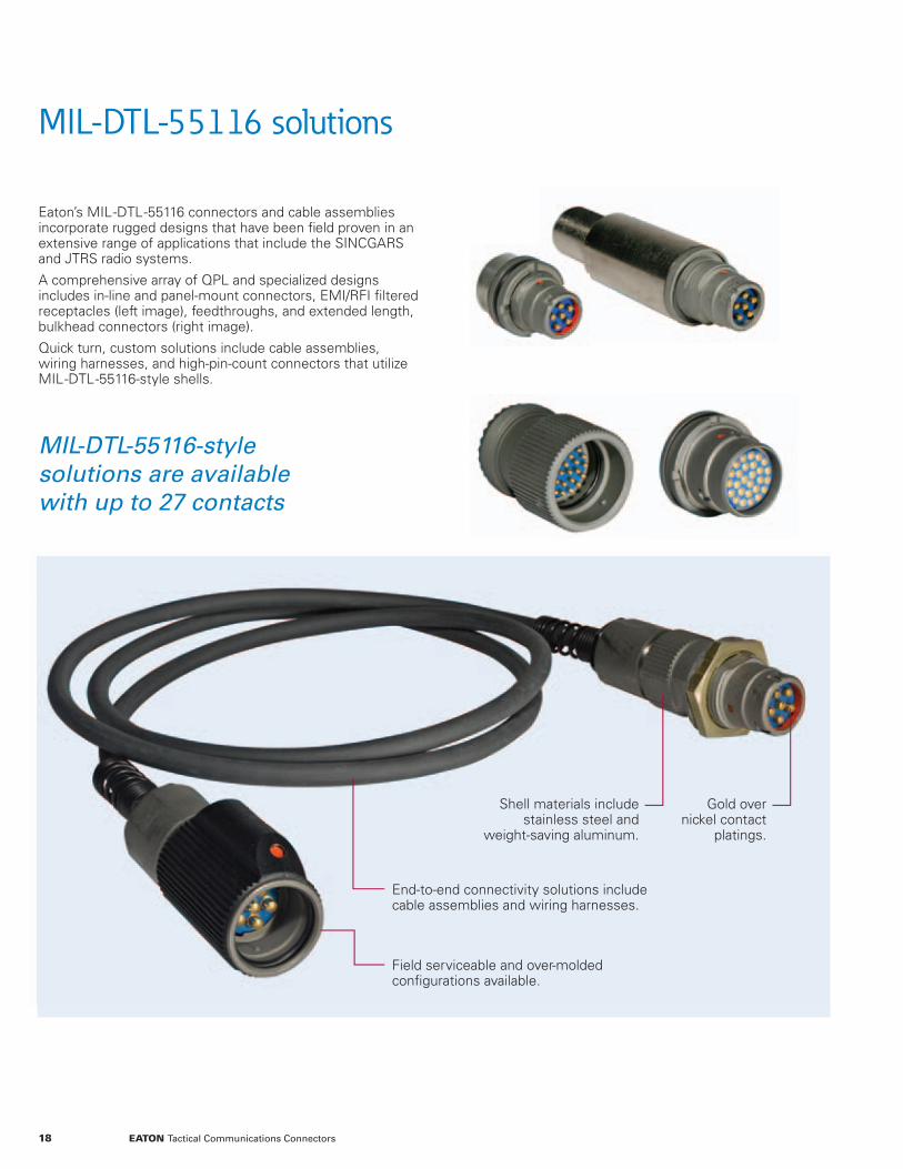
MIL-DTL-55116 solutions
Eaton’s MIL--DTL--55116 connectors and cable assemblies incorporate rugged designs that have been fi eld proven in an extensive range of applications that include the SINCGARS and JTRS radio systems.
A comprehensive array of QPL and specialized designs includes in-line and panel-mount connectors, EMI/RFI fi ltered receptacles (left image), feedthroughs, and extended length, bulkhead connectors (right image).
Quick turn, custom solutions include cable assemblies, wiring harnesses, and high-pin-count connectors that utilize MIL--DTL--55116-style shells.
MIL-DTL-55116-style solutions are available with up to 27 contacts
End-to-end connectivity solutions include cable assemblies and wiring harnesses.
Gold over nickel contact
platings.
Shell materials include stainless steel and
weight-saving aluminum.
Field serviceable and over-molded confi gurations available.
18 EATON Tactical Communications Connectors

Materials and Finishes
Shells And Panel Nuts Passivated Stainless Steel, Aluminum Shells Available as Noted on Detail PagesBackshell (Extended Receptacle) Nickel-Plated BrassContact Material Copper AlloyContact Plating Gold Over NickelInsert Diallyl Phthalate per MIL-M-14F, Type MDG
Electrical
Dielectric Strength 500 VRMSInsulation Resistance 1000 Megaohms MinimumContact Resistance (mated) 0.05 Ohms Maximum
Mechanical
Air Pressure 2.5 PSIWater Immersion 48 Hours at Six FeetMate/Unmate Durability 3000 Cycles
Solutions overview and general specifi cations
20 QPL, NSA and specialized plugs • M55116/1 to /8 • NSA ON241774-1 and -2 • Lightweight and right angle • Thread and fl ange panel mount
22 QPL, NSA, and fi ltered receptacles • M55116/11 to /14 • M55116/9 and /10 • NSA ON241775-1 to -5 • Application-optimized fi ltered solutions
23 Specialized receptacles • Extended bodies for bulkhead mounting • Double-ended feedthroughs
24 High-density solutions • 19 and 27 contact connectors • In-line, panel mount, and fi ltered confi gurationsDouble-ended feedthroughs
19EATON Tactical Communications Connectors
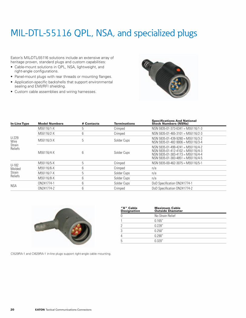
MIL-DTL-55116 QPL, NSA, and specialized plugs
Eaton’s MIL-DTL-55116 solutions include an extensive array of heritage proven, standard plugs and custom capabilities: • Cable-mount solutions in QPL, NSA, lightweight, and right-angle confi gurations.
• Panel-mount plugs with rear threads or mounting fl anges. • Application-specifi c backshells that support environmental sealing and EMI/RFI shielding.
• Custom cable assemblies and wiring harnesses.
In-Line Type Model Numbers # Contacts TerminationsSpecifi cations And National Stock Numbers (NSNs)
U-229WireStrainReliefs
M55116/1-X 5 Crimped NSN 5935-01-373-6341 = M55116/1-3M55116/2-X 6 Crimped NSN 5935-01-465-3101 = M55116/2-3
M55116/3-X 5 Solder Cups NSN 5935-01-439-9280 = M55116/3-2NSN 5935-01-482-9006 = M55116/3-4
M55116/4-X 6 Solder CupsNSN 5935-01-499-4241 = M55116/4-2NSN 5935-01-412-4102 = M55116/4-3NSN 5935-01-383-4173 = M55116/4-4NSN 5935-01-383-4851 = M55116/4-5
U-182MoldedStrainReliefs
M55116/5-X 5 Crimped NSN 5935-00-462-3075 = M55116/5-1M55116/6-X 6 Crimped n/aM55116/7-X 5 Solder Cups n/aM55116/8-X 6 Solder Cups n/a
NSAON241774-1 6 Solder Cups DoD Specifi cation ON241774-1ON241774-2 6 Crimped DoD Specifi cation ON241774-2
“X” Cable Designation
Maximum Cable Outside Diameter
0 No Strain Relief1 0.165”2 0.228”3 0.250”4 0.290”5 0.320”
CI529RA-1 and CI629RA-1 in-line plugs support right-angle cable mounting.
20 EATON Tactical Communications Connectors

MIL-DTL-55116 QPL, NSA, and specialized plugs
In-Line Plug Configurations
Lightweight PlugPart Number
CableSizes
ShellMaterial
*Weight(Ounces)
Five ContactsOvermolded Strain Reliefs
GC217-1-4 1/4” Stainless Steel 1.20GC217-3-16 3/16” Stainless Steel 1.20GC217A-1-4 1/4” Aluminum 0.81GC217A-3-16 3/16” Aluminum 0.81
Six ContactsOvermolded Strain Reliefs
GC617-1 -4 1/4” Stainless Steel 1.19GC617-3-16 3/16” Stainless Steel 1.19GC617A-1-4 1/4” Aluminum 0.80GC617A-3-16 3/16” Aluminum 0.80
* Approximate weight of QPL solutions is two ounces.
Type Part Number Contacts
In-line, 90° Cable EntryCI529RA-1 5CI629RA-1 6
The products listed above utilize stainless-steel shells, rigid contacts, and solder cup terminations.
Type Part Number Contacts Mounting
PanelMount
GC429 5 Rear ThreadGC529 6 Rear ThreadGC629 5 Square FlangeGC729 6 Square Flange
The products listed above utilize stainless-steel shells, rigid contacts, and solder cup terminations.
Lightweight Plugs are Approximately 50% Lighter than QPL Solutions*
Ø0.83”(Ø21.08mm)
Ø0.83”(Ø21.08mm)
Ø0.78”(Ø19.81mm)
Square Mounting Flange
0.78”(19.81mm)
0.22”(5.59mm)
0.94”(23.88mm)
0.78”(19.81mm)
0.50”(12.70mm)
1.31”(33.27mm)
0.17”(4.32mm)
1.17”(29.72mm)
0.27”(6.86mm)
GC629 and GC729GC429 and GC529CI529RA-1 and CI629RA-1
21EATON Tactical Communications Connectors
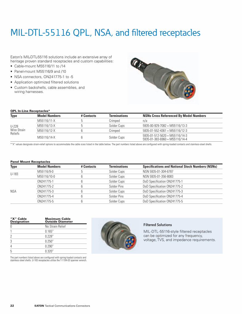
MIL-DTL-55116 QPL, NSA, and fi ltered receptacles
Eaton’s MIL-DTL-55116 solutions include an extensive array of heritage proven standard receptacles and custom capabilities: • Cable-mount M55116/11 to /14 • Panel-mount M55116/9 and /10 • NSA connectors, ON241775-1 to -5 • Application optimized fi ltered solutions • Custom backshells, cable assemblies, and wiring harnesses.
QPL In-Line Receptacles*
Type Model Numbers # Contacts Terminations NSNs Cross Referenced By Model Numbers
U-228Wire StrainReliefs
M55116/11-X 5 Crimped n/aM55116/13-X 5 Solder Cups 5935-00-929-7082 = M55116/13-3M55116/12-X 6 Crimped 5935-01-552-4361 = M55116/12-3
M55116/14-X 6 Solder Cups 5935-01-512-5620 = M55116/14-35935-01-383-6960 = M55116/14-4
*”X” values designate strain-relief options to accommodate the cable sizes listed in the table below. The part numbers listed above are confi gured with spring-loaded contacts and stainless-steel shells.
Panel Mount Receptacles
Type Model Numbers # Contacts Terminations Specifi cations and National Stock Numbers (NSNs)
U-183M55116/9-0 5 Solder Cups NSN 5935-01-304-6787M55116/10-0 6 Solder Cups NSN 5935-01-356-8083
NSA
ON241775-1 6 Solder Cups DoD Specifi cation ON241775-1ON241775-2 6 Solder Pins DoD Specifi cation ON241775-2ON241775-3 6 Solder Cups DoD Specifi cation ON241775-3ON241775-4 6 Solder Pins DoD Specifi cation ON241775-4ON241775-5 6 Solder Cups DoD Specifi cation ON241775-5
22 EATON Tactical Communications Connectors
“X” Cable Designation
Maximum Cable Outside Diameter
0 No Strain Relief1 0.165”2 0.228”3 0.250”4 0.290”5 0.320”
The part numbers listed above are confi gured with spring-loaded contacts and stainless-steel shells. U-183 receptacles utilize the T-1104-03 spanner wrench.
Filtered Solutions
MIL--DTL--55116-style fi ltered receptacles can be optimized for any frequency, voltage, TVS, and impedance requirements.
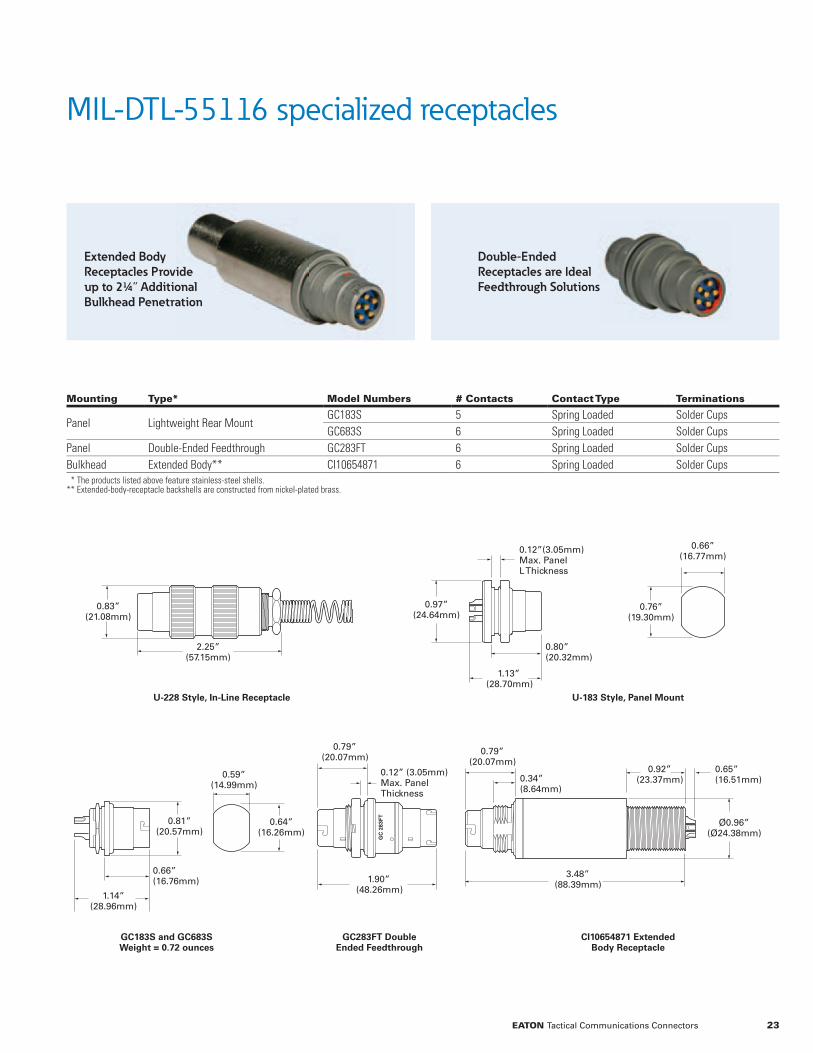
MIL-DTL-55116 specialized receptacles
Mounting Type* Model Numbers # Contacts Contact Type Terminations
Panel Lightweight Rear MountGC183S 5 Spring Loaded Solder CupsGC683S 6 Spring Loaded Solder Cups
Panel Double-Ended Feedthrough GC283FT 6 Spring Loaded Solder CupsBulkhead Extended Body** CI10654871 6 Spring Loaded Solder Cups * The products listed above feature stainless-steel shells. ** Extended-body-receptacle backshells are constructed from nickel-plated brass.
0.66”(16.77mm)
3.48”(88.39mm)
0.92”(23.37mm)
0.76”(19.30mm)
0.83”(21.08mm)
0.97”(24.64mm)
0.80”(20.32mm)
1.13”(28.70mm)
0.12”(3.05mm) Max. PanelL Thickness
2.25”(57.15mm)
Ø0.96”(Ø24.38mm)
0.65”(16.51mm)
0.79”(20.07mm)
1.90”(48.26mm)
0.79”(20.07mm)
0.59”(14.99mm)
0.81”(20.57mm)
0.66”(16.76mm)
1.14”(28.96mm)
0.64”(16.26mm)
0.12” (3.05mm) Max. Panel Thickness
0.34”(8.64mm)
U-228 Style, In-Line Receptacle
GC183S and GC683S Weight = 0.72 ounces
GC283FT Double Ended Feedthrough
CI10654871 Extended Body Receptacle
U-183 Style, Panel Mount
23EATON Tactical Communications Connectors
Extended Body Receptacles Provide up to 2¼” Additional Bulkhead Penetration
Double-Ended Receptacles are Ideal Feedthrough Solutions
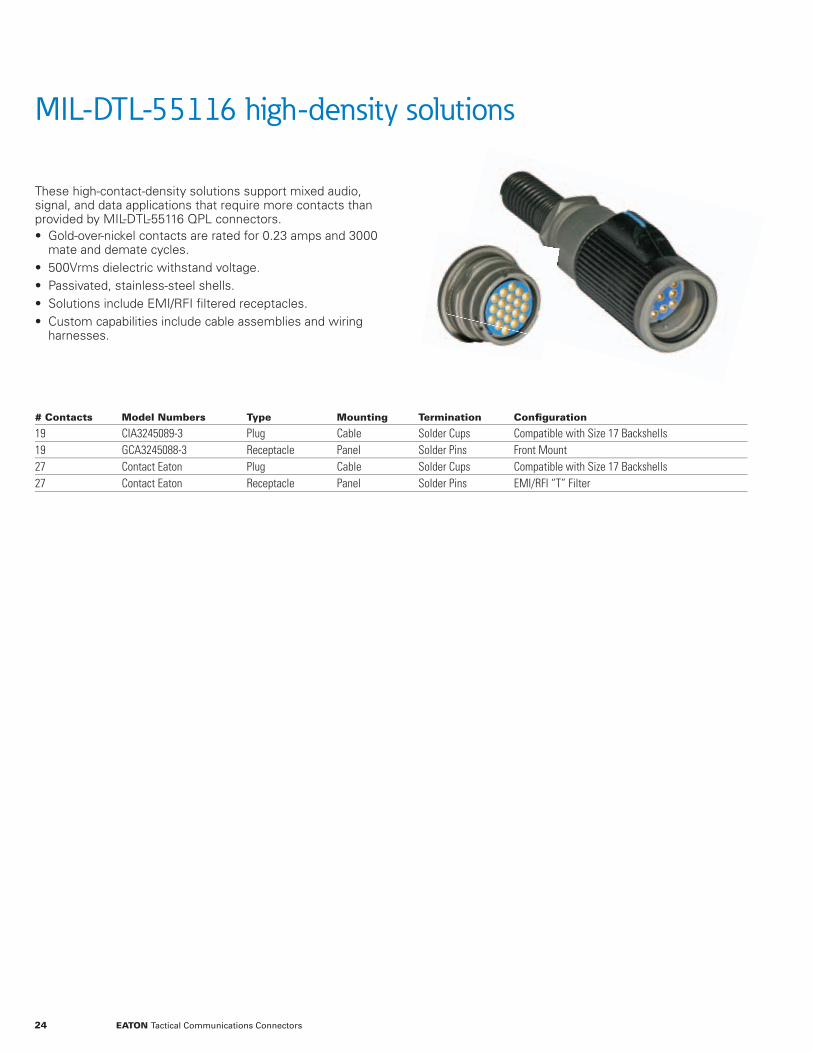
MIL-DTL-55116 high-density solutions
These high-contact-density solutions support mixed audio, signal, and data applications that require more contacts than provided by MIL-DTL-55116 QPL connectors. • Gold-over-nickel contacts are rated for 0.23 amps and 3000 mate and demate cycles.
• 500Vrms dielectric withstand voltage. • Passivated, stainless-steel shells. • Solutions include EMI/RFI fi ltered receptacles. • Custom capabilities include cable assemblies and wiring harnesses.
# Contacts Model Numbers Type Mounting Termination Confi guration
19 CIA3245089-3 Plug Cable Solder Cups Compatible with Size 17 Backshells19 GCA3245088-3 Receptacle Panel Solder Pins Front Mount27 Contact Eaton Plug Cable Solder Cups Compatible with Size 17 Backshells27 Contact Eaton Receptacle Panel Solder Pins EMI/RFI “T” Filter
24 EATON Tactical Communications Connectors

19-Contact CIA3245089-3
28 TeethPer MS27467,Shell Size 17
0.15”(3.81mm)
11-Contact CI1129RA-1
19-Contract GCA3245088-3
11-Contract CI1183-1
11-Contact CI1129-111-Contact CI1683
0.79”(19.99mm)
0.06”(1.52mm)
0.59”(14.99mm)
0.96”(24.38mm)
1.00”(25.4mm)
0.83”( 21.08mm)
0.91”(23.11mm)
0.69”(17.53mm)
1.51”( 38.35mm)
1.39”(35.31mm)
27-Contact Receptacle
Pins omittedfor clarity
0.29”(7.37mm)
0.85”(21.59mm)
27-Contact Plug
28 TeethPer MS27467,Shell Size 17
0.15”(3.81mm)
1.39”(35.31mm)
0.59”(14.99mm)
3.20”(81.28mm)
0.66”(16.76mm)
0.37”(9.40mm)
1.70”(43.18mm)
MIL-DTL-55116 high-density solutions
25EATON Tactical Communications Connectors

MIL-DTL-55181 solutions
Eaton offers a comprehensive range of MIL--DTL--55181 QPL and specialized solutions. This extensive range of fi eld-proven products can be leveraged to quickly develop application specifi c solutions including custom cable assemblies.
Innovations include a stacking connector that enables power splitting in the fi eld without the use of Y cables. The stacking connector incorporates plug contacts that are mated to the battery pictured to the right. Internal contacts split power between the attached cable and receptacle contacts that are mated to the QPL connector stacked on top of it.
Heritage-proven designs are rated for 500 mate and demate cycles.
Voltage drops for mated four-contact connectors less than 20mV at 35 amps; 9 and 18 contact models less than 25mV at 7.5 amps.
QPL and RoHS compliant fi nish options.
End-to-end solutions include custom-cable assemblies.
Gold over nickel contact platings.
Heat treated, alloy-steel nosepiece.
26 EATON Tactical Communications Connectors

MIL-DTL-55181 solutions overview
29 Panel-Mount Receptacles • QPL and Filtered Connectors • Transient Voltage Suppression Solutions
31 Cable-Mount Plugs • QPL and RoHS Compliant • Adaptor Series Simplifi es Shielding Terminations
33 Straight-Backshell Connectors • Plugs and Receptacles • Cable and Panel Mount
34 Stacking Connectors • Cable-Mounted Connectors Provide Front-Mounted Plug Contacts and Rear-Mounted Receptacle Contacts
35 Dual-Header Receptacles • Cable-Mounted Connectors Provide Two Sets of Receptacle Contacts
36 Dual Cable Entry Plugs • Provides Plug Contacts and Connections for Two Cables
37 Multiple Power Access Units • Provides Plug Contacts, a Cable Connection, and Receptacle Contacts
38 Accessories and Installation Instructions • Dust Covers and Spanner Wrenches • Torque Specifi cations
Adaptor Series Simplifi es Shielding Terminations
Stacking Connectors
MIL-DTL-55181 general specifi cations – page 28
Front
Front
Rear
Rear
27EATON Tactical Communications Connectors

MIL-DTL-55181 general specifi cations
Materials And Finishes
ShellsPlugs Aluminum Alloy Body, Steel Alloy Nosepieces, Cadmium Plate with Olive Drab ChromateReceptacles Brass, Cadmium Plate with Olive Drab ChromateSpanner Nut Brass, Olive Drab ChromateDraw Screws Stainless SteelContactsSocket Copper Alloy with Berylium-Copper Spring, Gold Over Nickel PlatingPin Yellow Brass, Gold Over Nickel PlatingInsulator Glass-Filled Diallyl Phthalate, Type GDF-30 F or SDG F
Electrical
Dielectric Strength - 4 Contacts 200 Volts RMSDielectric Strength - 9 And 18 Contacts 1500 Volts RMSInsulation Resistance 1000 Megohms Minimum at 500 Volts DCVoltage Drop - 4 Contacts 20 mV at 35 AmpsVoltage Drop - 9 And 18 Contacts 25 mV at 7.5 Amps
Mechanical
Air Pressure 2.5 PSIWater Immersion 6 Feet for 48 HoursDurability 500 Cycles with a Coupling Torque of 25 Inch PoundsContact Retention 10 PoundsInsert Strength 400 Pounds
MIL-DTL-55181 end-to-end connectivity solutions include quick turn, custom cable assemblies.
28 EATON Tactical Communications Connectors

MIL-DTL-55181 panel-mount receptacles
• QPL--certifi ed 4, 9, and 18-contact confi gurations. • Gold over nickel contacts. • Rated for 500 mate/demate cycles. • Please refer to the accessories section for dust cap and backshell information.
• Custom capabilities include factory installed wiring harnesses and cable assemblies.
Government Designation
Alternate Designation # Contacts Contact Type Contact Size
Amps/ Contact Termination NSN
M55181/2-01 MW20M(M)A00 4 Pin 12 35 Turret 5935-01-378-9152M55181/4-01 MW20F(M)A00 4 Socket 12 35 Turret 5935-01-199-7156M55181/6-01 MW20F(M)B00 9 Socket 20 7.5 Solder Cup 5935-00-853-5942M55181/8-01 MW20F(M)D00 18 Socket 20 7.5 Solder C up 5935-00-133-0394Please refer to the MIL-DTL-55181 general specifi cations table for additional information.
Backshells facilitate cable attachments and shielding. Please contact Eaton for additional information.
Panel cutout for /2, /4, /6 & /8Recommended panel thickness 0.125”
Solder turret and solder cup confi gurations share the same dimensions
1.25” (31.75mm) -18NEF-2A
0.13” (3.18mm) four places
1.26”(32.00mm)
1.18”(30.07mm)
0.85”(21.59mm)
0.38”(9.60mm)
1.47”(37.29mm)
1.44”(36.50mm)
Backshells facilitate cable attachments and shielding. Please contact Eaton for additional information.Backshells facilitate cable attachments and shielding. Please contact Eaton for additional information.
29EATON Tactical Communications Connectors

MIL-DTL-55181 filtered receptacles
• Application optimized filter solutions are available to support a broad range of requirements.
• 8, 9, and 18 pin panel-mount configurations. • Please refer to the accessories section for dust cap information.
• Custom capabilities include factory installed wiring harnesses and cable assemblies.
• Contact Eaton to discuss filter solutions optimized for your exact voltage, frequency, and impedance requirements.
Rugged, high-density filter designs can be optimized for any frequency, voltage, and impedance requirements.
Additional design options include transient voltage suppression.
30 EATON Tactical Communications Connectors
C Filter
L Filter T Filter
Pi Filter
1.87”(47.5mm)
1.49”(37.85mm)
0.50”(12.70mm)
0.13”(3.30mm) four places
1.44”(36.58mm)
1.47”(37.29mm)

MIL-DTL-55181 QPL plugs
• Finish options include zinc nickel, cadmium plating, and electroless nickel with black-trivalent chromate.
• Gold over nickel contacts. • Heat treated, alloy-steel nosepiece. • Rated for 500 mate and demate cycles. • Custom capabilities include wiring harnesses and cable assemblies.
Government Designation
Alternate Designation Description
Cable Ø(Inches) NSN
M55181/1-01 MW10F(M)A11# Sockets : 4Socket Size: 12Amps/Socket: 35Termination: Turret
0.292 – 0.343 5935-00-603-6952M55181/1-02 MW10F(M)A13 0.323 – 0.406 5935-01-204-7312M55181/1-03 MW10F(M)A17 0.448 – 0.531 5935-00-921-3399M55181/1-04 MW10F(M)A19 0.511 – 0.593 5935-01-249-7559M55181/1-05 MW10F(M)A15 0.386 – 0.468 5935-01-329-4190M55181/3-01 MW10M(M)A11
# Pins : 4Pin size: 12Amps/Pin: 35Termination: Turret
0.292 – 0.343 5935-01-208-2345M55181/3-02 MW10M(M)A13 0.323 – 0.406 5935-01-124-9341M55181/3-03 MW10M(M)A17 0.448 – 0.531 5935-01-167-6095M55181/3-04 MW10M(M)A19 0.511 – 0.593 n/aM55181/3-05 MW10M(M)A15 0.386 – 0.468 n/aM55181/5-01 MW10M(M)B11
# Pins : 9Pin Size: 20Amps/Pin: 7.5Termination: Solder Cup
0.292 – 0.343 5935-01-184-1460M55181/5-02 MW10M(M)B13 0.323 – 0.406 5935-01-149-1162M55181/5-03 MW10M(M)B17 0.448 – 0.531 5935-01-081-6484M55181/5-04 MW10M(M)B19 0.511 – 0.593 n/aM55181/5-05 MW10M(M)B15 0.386 – 0.468 n/aM55181/7-01 MW10M(M)D11
# Pins : 18Pin Size: 20Amps/Pin: 7.5Termination: Solder Cup
0.292 – 0.343 5935-01-111-9956M55181/7-02 MW10M(M)D13 0.323 – 0.406 5935-01-116-3608M55181/7-03 MW10M(M)D17 0.448 – 0.531 5935-00-815-2325M55181/7-04 MW10M(M)D19 0.511 – 0.593 5935-01-300-3701M55181/7-05 MW10M(M)D15 0.386 – 0.468 5935-01-329-8690Please refer to the MIL-DTL-55181 general specifi cations table for additional information.Cadmium plating requires no fi nish designation. Add a “Z” suffi x for zinc nickel or a “F” suffi x for electroless nickel with black trivalent chromate, i.e., M55181/1-03Z.
1.47”(37.34mm)
2.13”(53.98mm)2.50”
(63.50mm)
0.93”(23.50mm)
1.59”(40.26mm)
0.63”(15.88mm)
31EATON Tactical Communications Connectors
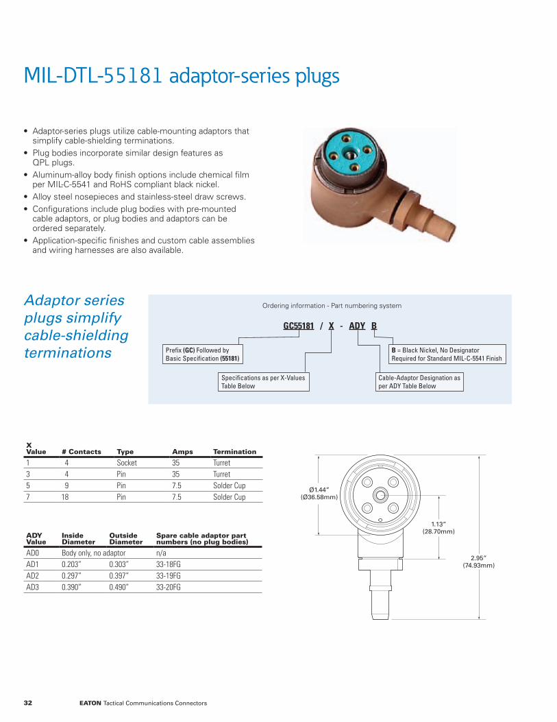
MIL-DTL-55181 adaptor-series plugs
X Value # Contacts Type Amps Termination
1 4 Socket 35 Turret3 4 Pin 35 Turret5 9 Pin 7.5 Solder Cup7 18 Pin 7.5 Solder Cup
ADYValue
InsideDiameter
OutsideDiameter
Spare cable adaptor part numbers (no plug bodies)
AD0 Body only, no adaptor n/aAD1 0.203” 0.303” 33-18FGAD2 0.297” 0.397” 33-19FGAD3 0.390” 0.490” 33-20FG
• Adaptor-series plugs utilize cable-mounting adaptors that simplify cable-shielding terminations.
• Plug bodies incorporate similar design features as QPL plugs.
• Aluminum-alloy body finish options include chemical film per MIL-C-5541 and RoHS compliant black nickel.
• Alloy steel nosepieces and stainless-steel draw screws. • Configurations include plug bodies with pre-mounted cable adaptors, or plug bodies and adaptors can be ordered separately.
• Application-specific finishes and custom cable assemblies and wiring harnesses are also available.
Ordering information - Part numbering system
GC55181 / X - ADY B
Prefix (GC) Followed by Basic Specification (55181)
Specifications as per X-Values Table Below
B = Black Nickel, No Designator Required for Standard MIL-C-5541 Finish
Cable-Adaptor Designation as per ADY Table Below
Adaptor series plugs simplify cable-shielding terminations
Ø1.44”(Ø36.58mm)
2.95”(74.93mm)
1.13”(28.70mm)
32 EATON Tactical Communications Connectors

Straight backshell MIL-DTL-55181 connectors
X Value # Contacts Type
Contact Type Amps
Contact Size Termination
1 4 Plug Socket 35 12 Turret2 4 Receptacle Pin 35 12 Turret3 4 Plug Pin 35 12 Turret4 4 Receptacle Socket 35 12 Turret5 9 Plug Pin 7.5 20 Solder Cup6 9 Receptacle Socket 7.5 20 Solder Cup7 18 Plug Pin 7.5 20 Solder Cup8 18 Receptacle Socket 7.5 20 Solder Cup
Please refer to the MIL-DTL-55181 general specifi cations table for additional information.
ZZ Value
Cable Diameter (Inches)
01 .292 to .34302 .323 to .40503 .448 to .53104 .511 to .59305 .386 to .468
• Suitable for in-line and panel-mount applications. • Shielded ferrules facilitate cable-shield terminations. • Finish options include cadmium chromate, electroless-nickel, and RoHS compliant electroless nickel with black-trivalent chromate.
• Custom capabilities include wiring harnesses and cable assemblies.
Ordering information - Part numbering system
CI 55181 / X - 01SB Y - ZZ
Prefix (CI) Followed by Basic Specification (55181)
Specifications as per X-Values Table Below
Cable Size Designator as per ZZ-Values Table Below
E = Cadmium; N = Nickel; B = RoHS Complaint Black Nickel
Ø1.47”(Ø37.34mm)
3.22”(81.79mm)
Front Shell
Front Shell
Coupling NutBack Shell Back Shell
GrommetShield Ferrule
FerruleCable Nut
3.60”( 91.44mm)
Suitable for cable and panel-mount applications
33EATON Tactical Communications Connectors
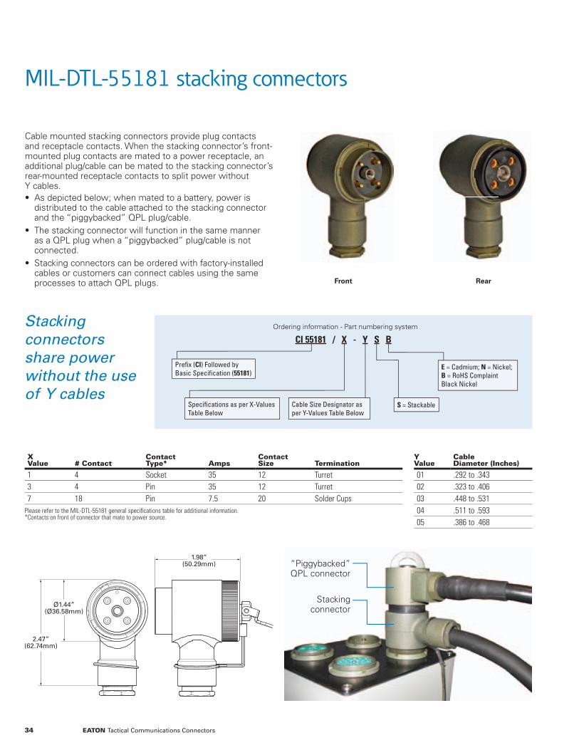
MIL-DTL-55181 stacking connectors
Cable mounted stacking connectors provide plug contacts and receptacle contacts. When the stacking connector’s front-mounted plug contacts are mated to a power receptacle, an additional plug/cable can be mated to the stacking connector’s rear-mounted receptacle contacts to split power without Y cables.• As depicted below; when mated to a battery, power is
distributed to the cable attached to the stacking connector and the “piggybacked” QPL plug/cable.
• The stacking connector will function in the same manner as a QPL plug when a “piggybacked” plug/cable is not connected.
• Stacking connectors can be ordered with factory-installed cables or customers can connect cables using the same processes to attach QPL plugs.
X Value # Contact
Contact Type* Amps
Contact Size Termination
1 4 Socket 35 12 Turret3 4 Pin 35 12 Turret7 18 Pin 7.5 20 Solder Cups
Please refer to the MIL-DTL-55181 general specifi cations table for additional information.*Contacts on front of connector that mate to power source.
Y Value
Cable Diameter (Inches)
01 .292 to .34302 .323 to .40603 .448 to .53104 .511 to .59305 .386 to .468
Ordering information - Part numbering system
CI 55181 / X - Y S B
S = StackableSpecifications as per X-Values Table Below
E = Cadmium; N = Nickel; B = RoHS Complaint Black Nickel
Cable Size Designator as per Y-Values Table Below
Prefix (CI) Followed by Basic Specification (55181)
Stacking connectors share power without the use of Y cables
Front Rear
1.98”(50.29mm)
Ø1.44”(Ø36.58mm)
2.47”(62.74mm)
“Piggybacked” QPL connector
Stacking connector
34 EATON Tactical Communications Connectors
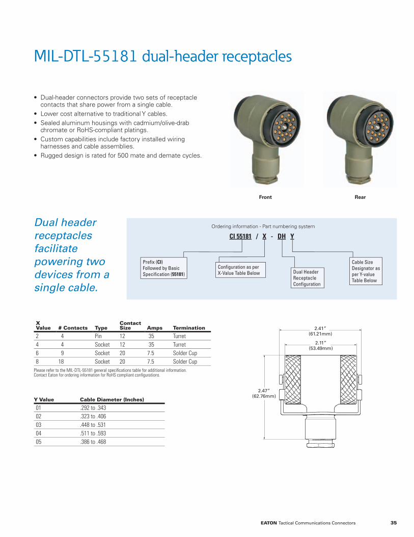
MIL-DTL-55181 dual-header receptacles
X Value # Contacts Type
Contact Size Amps Termination
2 4 Pin 12 35 Turret4 4 Socket 12 35 Turret6 9 Socket 20 7.5 Solder Cup8 18 Socket 20 7.5 Solder Cup
Please refer to the MIL-DTL-55181 general specifi cations table for additional information. Contact Eaton for ordering information for RoHS compliant confi gurations.
• Dual-header connectors provide two sets of receptacle contacts that share power from a single cable.
• Lower cost alternative to traditional Y cables. • Sealed aluminum housings with cadmium/olive-drab chromate or RoHS-compliant platings.
• Custom capabilities include factory installed wiring harnesses and cable assemblies.
• Rugged design is rated for 500 mate and demate cycles.
Y Value Cable Diameter (Inches)
01 .292 to .34302 .323 to .40603 .448 to .53104 .511 to .59305 .386 to .468
Ordering information - Part numbering system
Configuration as per X-Value Table Below Dual Header
Receptacle Configuration
Cable Size Designator as per Y-value Table Below
CI 55181 / X - DH Y
Prefix (CI) Followed by Basic Specification (55181)
Dual header receptacles facilitate powering two devices from a single cable.
2.41”(61.21mm)
2.11”(53.49mm)
2.47”(62.76mm)
Front Rear
35EATON Tactical Communications Connectors

1.09”(27.69mm)
1.09”(27.69mm)
1.15”(29.21mm)
1.15”(29.21mm)
Location 1
Location 2
90° or 70°
Dual cable entry MIL-DTL-55181 plugs
X Value
# Contacts
Contact Type
Contact Size Amps Termination
1 4 Socket 12 35 Turret3 4 Pin 12 35 Turret5 9 Pin 20 7.5 Solder Cup7 18 Pin 20 7.5 Solder Cup
Please refer to the MIL-DTL-55181 general specifications table for additional information. Contact Eaton for ordering information for RoHS compliant configurations.
ADYZ Value Adaptor ID Adaptor OD
1 .203 .3032 .297 .3973 .390 .490
• Dual-entry connectors incorporate a single-plug body that distributes power to two cables.
• Available with 75° and 90° cable-entry configurations. • Sealed aluminum housings with cadmium/olive-drab chromate or RoHS-compliant platings.
• Custom capabilities include wiring harnesses and cable assemblies.
Ordering information - Part numbering system
CI 55181 / X - DE 75 ADYZ
Prefix (CI) Followed by Basic Specification (55181)
Configuration as per X-Value Table Below
Dual Entry Cable Configuration
Entry Orientation - Leave Blank for 90° Entry, “75” Designates 75° Entry
“AD” Followed by Two Adaptor Designators From the ADYZ-value Table Below. Example: “AD23” Designates a .297” ID Adaptor #1 and a .390”ID Adaptor #2
Dual-entry plugs facilitate lower cost solutions than traditional Y cables.
36 EATON Tactical Communications Connectors

MIL-DTL-55181 multiple power access units
Multiple Power Access Units (MPAUs) provide two power outputs from a single input. The MPAU body incorporates a cable adaptor and a receptacle to facilitate power splitting from a plug that connects to the power source. Additional features and specifi cations include: • Meets MIL--DTL--55181 electrical, mechanical, and environmental requirements.
• Ideal solutions for height-constrained applications. • Quickly replaces QPL plugs by using standard MIL--DTL--55181 plug-to-cable attachment processes.
• Extensive range of solutions includes standard products and application-specifi c confi gurations.
Part Number # Contacts Plug Contacts Receptacle ContactsCable Adaptor Inside/Outside Ø
Connector Orientations With Plug Mated In Downward Position
MPAUP/1-2A-2B0175 4 Sockets Pins 0.297”/0.397” Receptacle Left / Cable RightMPAUP/3-4A-2BL175 4 Sockets Pins 0.297”/0.397” Receptacle Right / Cable Left
Multiple power access units can be confi gured to support a broad range of requirements including: • 4, 9 or 18 contacts. • RoHS-compliant fi nishes. • Alternate confi gurations including a 90° offset from the cable adapter to the receptacle as depicted to the left.
• Adapters to accommodate any a wide range of cable diameters.
• End-to-end connectivity solutions include cable assemblies and wiring harnesses.
MPAUP/1-2A-2B0175 – The receptacle is oriented to the left with the plug facing forward.
MPAUP/3-4A-2BL175 – The receptacle is oriented to the right with the plug facing forward.
1.55”(39.37mm)
2.24”( 56.90 mm)
Key way
Plug
Receptacle
2.77”(70.36mm)
75°
45°
Key way
Plug
Receptacle
75°
45°
37EATON Tactical Communications Connectors
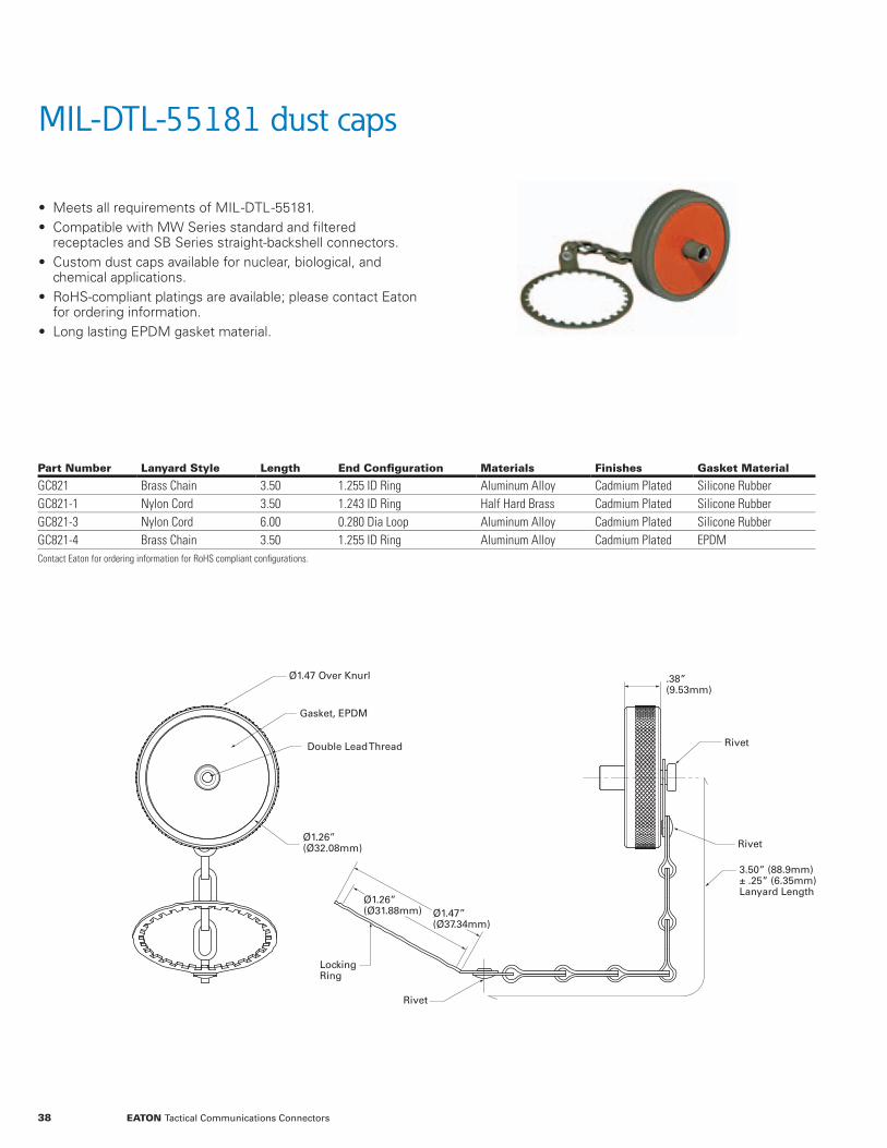
MIL-DTL-55181 dust caps
• Meets all requirements of MIL--DTL--55181. • Compatible with MW Series standard and fi ltered receptacles and SB Series straight-backshell connectors.
• Custom dust caps available for nuclear, biological, and chemical applications.
• RoHS-compliant platings are available; please contact Eaton for ordering information.
• Long lasting EPDM gasket material.
Part Number Lanyard Style Length End Confi guration Materials Finishes Gasket Material
GC821 Brass Chain 3.50 1.255 ID Ring Aluminum Alloy Cadmium Plated Silicone RubberGC821-1 Nylon Cord 3.50 1.243 ID Ring Half Hard Brass Cadmium Plated Silicone RubberGC821-3 Nylon Cord 6.00 0.280 Dia Loop Aluminum Alloy Cadmium Plated Silicone RubberGC821-4 Brass Chain 3.50 1.255 ID Ring Aluminum Alloy Cadmium Plated EPDMContact Eaton for ordering information for RoHS compliant confi gurations.
Ø1.47 Over Knurl
Gasket, EPDM
Double Lead Thread
Ø1.26”(Ø32.08mm)
Ø1.26”(Ø31.88mm) Ø1.47”
(Ø37.34mm)
.38”(9.53mm)
Rivet
Rivet
3.50” (88.9mm) ± .25” (6.35mm)Lanyard Length
Locking Ring
Rivet
38 EATON Tactical Communications Connectors

MIL-DTL-55181 tools and assembly instructions
Mounting ConnectorsSpanner Wrench Part Number
Driver Compatibility
Recommended Spanner Wrench Torque
Recommended Cable Nut Torque
Panel QPL Receptacles T-1104-02 3/8” 21 - 33 Foot Pounds N/APanel Filtered Receptacles T-1104-02 3/8” 21 - 33 Foot Pounds N/ACable QPL Plugs T-1104-01 3/8” 90 - 95 Inch Pounds 34 - 40 Inch PoundsCable SB Series Receptacles T-1104-02 3/8” 21 - 33 Foot Pounds 34 - 40 Inch PoundsCable Stacking Connectors T-1104-01 3/8” 90 - 95 Inch Pounds 34 - 40 Inch PoundsCable Dual Entry Plugs T-1104-01 3/8” 90 - 95 Inch Pounds 34 - 40 Inch PoundsCable Dual Header Receptacles T-1104-01 3/8” 90 - 95 Inch Pounds 34 - 40 Inch Pounds
• Spanner wrenches are specifically designed to provide positive engagements with the MIL--DTL--55181 specified, slotted nuts depicted to the right.
• T--1104-01 and T--1104-02 spanner wrenches are compatible with 3/8” drive torque wrenches.
• QPL, filtered, and straight backshell connectors can be assembled in accordance with MIL--DTL--55181 assembly instructions.
• Please contact Eaton for stacking, dual entry, and dual-header connector assembly instructions.
1.30”(33.02mm)
1.53”(38.86mm)
1.44”(36.5mm)
1.53”(38.86mm)
MW10 connectors utilize the T -1104-01 spanner wrench. MW20 connectors utilize the T -1104-02 spanner wrench.
39EATON Tactical Communications Connectors
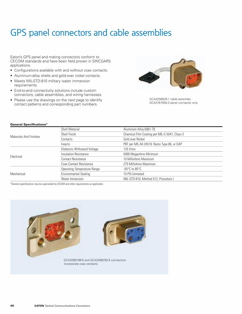
GPS panel connectors and cable assemblies
Eaton’s GPS panel and mating connectors conform to CECOM standards and have been fi eld proven in SINCGARS applications. • Confi gurations available with and without coax contacts. • Aluminum-alloy shells and gold-over nickel contacts. • Meets MIL-STD-810 military water immersion requirements.
• End-to-end connectivity solutions include custom connectors, cable assemblies, and wiring harnesses.
• Please use the drawings on the next page to identify contact patterns and corresponding part numbers.
General Specifi cations*
Materials And Finishes
Shell Material Aluminum Alloy 6061-T6Shell Finish Chemical Film Coating per MIL-C-5541, Class 3Contacts Gold over NickelInserts PBT per MIL-M-24519, Nylon Type 66, or DAP
Electrical
Dielectric Withstand Voltage 125 VrmsInsulation Resistance 5000 Megaohms MinimumContact Resistance 10 Milliohms MaximumCoax Contact Resistance 275 Milliohms Maximum
MechanicalOperating Temperature Range -55°C to 85°CEnvironmental Sealing 15 PSI UnmatedWater Immersion MIL-STD-810, Method 512, Procedure I
*General specifi cations may be superseded by CECOM and other requirements as applicable.
GCA3256628-1 cable assemblyGCA3167930-3 panel connector only
GCA3266198-5 and GCA3266293-5 connectors incorporate coax contacts.
40 EATON Tactical Communications Connectors

1.31”(33.27mm)
1.82”(46.23mm)
0.67”(17.02mm)
1.31”(33.27mm)
3.25”(82.55mm)
0.67”(17.02mm)
1.05”(26.67mm)
GPS panel connectors and cable assemblies
GCA3266293-5, socket contacts
GCA3266198-5, pin contacts
GCA3266293-6, socket contacts
GCA3167930-3, pin contacts GCA3256628-1 cable assembly includes GCA3167930-3 connector
Solutions with coax contacts
Solutions without coax contacts
41EATON Tactical Communications Connectors

MIL-DTL-26482 shell size 10
Shell size 10 connectors are available with insert patterns that meet the requirements of a broad range of military specifi cations and programs including: • DEF STAN Patterns 105, 602, and 603 • BS 9522 N0001 and BS 9522 F0017 • PAN 6432-1 and PAN 6432-4 • Bowman and Clansman radio systems • VIC 3 and VIC 5 vehicular intercom systems
Custom capabilities include application-specifi c shells and inserts, EMI/RFI fi ltering, and cable assemblies.
Series Designations
Confi guration Series Cable/Backshell Attachment Coupling NutPanel Mount Receptacle* 2655 n/a n/a
Cable Mount Plug
2655 Overmold Compatible n/a2656 Threaded, no Teeth Short2657 Threaded with Teeth Short2658 Threaded, no Teeth Long2659 Threaded with Teeth Long
* Receptacles utilize the round, slotted-nut confi guration depicted at the top of this page.
MIL-DTL-26482 shell size 10 ordering information
CIX 265X - 10 WW X YY Z GG
CI Prefix Followed by C = Cable or P = Panel Mount
Panel Mount Ground-Pin Location: 1, 2, 3, 4, 5, or 6
Series as per Table Below Second Master Key Location: 0, 1, 2, 3, or 4
Insert Arrangement: 02, 06, 07, or 76 S = Socket or P = Pin Contacts
Shell Size 10 Keyway Orientation as per Keyway Table
02 insert 2 contacts 16AWG
06 insert 6 contacts 20AWG
07 insert 7 contacts 20AWG
76 insert 7 contacts 20AWG 6 contacts 22AWG
Ground pin locations for panel-mount receptacles
1
2
34
5
6
42 EATON Tactical Communications Connectors

MIL-DTL-26482 shell size 10
Orientations Table
Designation a b c dN0 105 35 110 160A0 95 35 110 160B0 85 35 110 160C0 125 35 110 160D0 115 35 110 160E0 115 30 130 160F0 85 50 125 170B2 85 41 110 160E2 115 36 130 160E3 115 30 124 160F1 85 50 125 170
Cable mount keyway orientations
a
b
c
d
Panel mount keyway orientations
a
b
cd
Panel mount second master keyway orientations
Position 0
Position 4
Position 3
Position 2
Position 1
Cable mount second master keyway orientations
Position 0
Position 1
Position 2Position 3
Position 4
Contact Eaton to discuss additional
MIL-DTL-26482 shell sizes and
custom configurations
43EATON Tactical Communications Connectors

Battery connectors – panel mount and in-line
Eaton’s ruggedized battery connectors include six pin panel mount and miniaturized in-line solutions. • Panel-mount connectors provide mating compatibility to BB-590/U batteries; standard options include ferrite topology EMI/RFI protection.
• In-line connectors are designed for rugged environment, space constrained applications such as military handsets.
• Custom solutions include application-specifi c materials, pin confi gurations, mounting fl anges, and wiring harnesses.
Panel Mount Battery Connector Specifi cations
Materials And Finishes
Shell Material Aluminum Alloy 6061-T6Shell Finish Chemical Film Coating per MIL-C-5541, Class 1AContact Material/Plating Brass Alloy 360, ½ H per QQ-B-626/Gold over NickelInserts DAP Resin per MIL-M-14, TYP MDG, Color Blue
ElectricalCurrent Rating 10 AmpsInsulation Resistance 500 VDCContact Resistance (Mated) 5 mv Maximum at Ambient Temperature
MechanicalShell Size 12Environmental Sealing 15 PSI UnmatedMating Compatibility BB-590/U Battery per MIL-B-494436/1
Ordering Information Contact Eaton for Part Numbers and Ordering Information
Relative sizes not to scale
Miniaturized in-line battery connectors and cable assemblies
Eaton offers a library of heritage-proven designs, and modifi ed/custom solution capabilities, to support in-line battery connector and cable assembly requirements for military-handset applications.
General Description
Hermaphroditic connector design utilizing mirrored power/ground wires on mated pairs to maintain red/black color coding throughout the host system
CustomCapabilities
Application-specifi c materials, platings, contact and wire sizes, and custom cables and wiring harnesses
Ordering Information Contact Eaton to discuss your application requirements
Heritage proven design features
0.190” (4.83mm) wide shell can support a wide range of handset-application requirements
Gold-plated contacts
Redundant contacts
44 EATON Tactical Communications Connectors

Battery connectors – mechanical drawings
Panel-mount connectors
In-line connectors
6.00”(152.40mm)
Black Wire
Black Wire
Red Wire
Red Wire
1.06”(26.97mm)
0.43”(10.92mm)
0.33”(8.38mm)
0.80”(20.32mm)
0.190”(4.83mm)
6.00”(152.40mm)
0.190”(4.83mm)
Panel-Mount Battery Connector
A1-374-0000
A1-375-0000
45EATON Tactical Communications Connectors

Power tray connectors
Eaton’s power tray connectors are designed to withstand the high shock and vibration encountered in ground mobile, tactical radio applications. Additional features include: • Thirty-year track record includes qualifi cations for multiple tactical-communications programs including SINCGARS.
• Solutions are available to support power, data, and hybrid interconnect requirements.
• End-to-end connectivity solutions include custom cable assemblies and wiring harnesses.
General Specifi cations*
Materials And Finishes
Shell Material Cast Aluminum, Cadmium Chromate Olive Drab PlatingContacts Copper Alloy with Gold-Over-Nickel PlatingInserts NeopreneGaskets Neoprene or Rubber Per MIL-R-3065Rear Insulators Diallyl Phthalate
Electrical
Dielectric Withstand Voltage 1000 Vrms MinimumInsulation Resistance 5000 Megaohms Minimum#16 Contact Current Rating 10 Amps#12 Contact Current Rating 15 Amps
Mechanical
Operating Temperature Range -55°C To 100°CEnvironmental Sealing 15 PSI UnmatedWater Immersion MIL-STD-810, Method 512, Procedure IMate/Unmate Durability 500 Cycles
*General specifi cations may be superseded by CECOM and other requirements as applicable.
Rugged, cast aluminum shells
30-year heritage includes SINCGARS
Gold-over-nickel plated contacts
Confi gurations available with integral EMI/RFI fi ltering
Rated for 500 mate and demate cycles
46 EATON Tactical Communications Connectors

Power tray connectors
Contact Sizes
Contact Type CECOM Part Number Eaton Part Number Configuration
3 #1215 #16
SocketsA3012771-1 & -2 A3012771-2 Three Non-Threaded Mounting HolesA3012771-3 U-344/VRCG4 Four Non-Threaded Mounting Holesn/a U-344/VRC Two Non-Threaded Mounting Holes
Pins
A3012772-1 A3012772-1 Non-Threaded Mounting HolesA3012772-2 A3012772-2 Grounded Shell, Threaded Mounting Through HolesA3012772-3 CIA3012772-3 Grounded Shell, Blind Threaded Mounting Holesn/a U-345/VRC 1500 pF Filtering, Blind Threaded Mounting Holesn/a U-345/VRCG7 ESD Protection, 1500 pF Filtering
4 #1242 #20
Sockets n/a CI344-4-42 Three Non-Threaded Mounting HolesPins n/a CI345-4-42 Grounded Shell, Blind Threaded Mounting Holes
3.51”(89.15mm)
2.61”(66.29mm)
2.78”(70.61mm)
3.52”(89.41mm)
4.62”(117.35mm)
1.60”(40.64mm)
1.72”(43.69mm)
2.78”(70.61mm)
1.72”(43.69mm)
1.59”(39.37mm)
1.14”(28.96mm)
1.60”(40.64mm)
A3012771-2
18 Pin Configurations
U344/VRCG4
CI344-4-42
U344/VRC
CI345-4-42
47EATON Tactical Communications Connectors
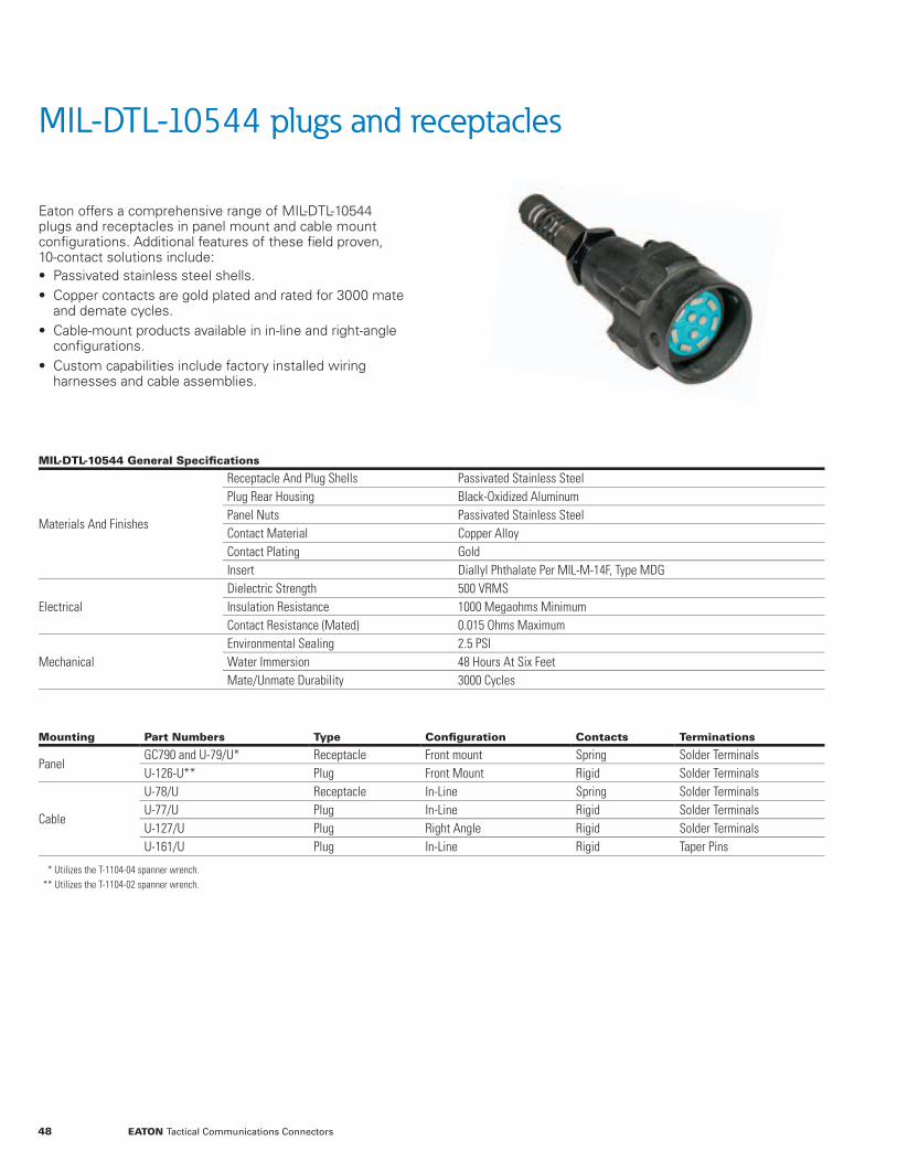
MIL-DTL-10544 plugs and receptacles
Eaton offers a comprehensive range of MIL-DTL-10544 plugs and receptacles in panel mount and cable mount confi gurations. Additional features of these fi eld proven, 10-contact solutions include: • Passivated stainless steel shells. • Copper contacts are gold plated and rated for 3000 mate and demate cycles.
• Cable-mount products available in in-line and right-angle confi gurations.
• Custom capabilities include factory installed wiring harnesses and cable assemblies.
MIL-DTL-10544 General Specifi cations
Materials And Finishes
Receptacle And Plug Shells Passivated Stainless SteelPlug Rear Housing Black-Oxidized AluminumPanel Nuts Passivated Stainless SteelContact Material Copper AlloyContact Plating GoldInsert Diallyl Phthalate Per MIL-M-14F, Type MDG
ElectricalDielectric Strength 500 VRMSInsulation Resistance 1000 Megaohms MinimumContact Resistance (Mated) 0.015 Ohms Maximum
MechanicalEnvironmental Sealing 2.5 PSIWater Immersion 48 Hours At Six FeetMate/Unmate Durability 3000 Cycles
Mounting Part Numbers Type Confi guration Contacts Terminations
PanelGC790 and U-79/U* Receptacle Front mount Spring Solder TerminalsU-126-U** Plug Front Mount Rigid Solder Terminals
Cable
U-78/U Receptacle In-Line Spring Solder TerminalsU-77/U Plug In-Line Rigid Solder TerminalsU-127/U Plug Right Angle Rigid Solder TerminalsU-161/U Plug In-Line Rigid Taper Pins
*** Utilizes the T-1104-04 spanner wrench.*** Utilizes the T-1104-02 spanner wrench.
48 EATON Tactical Communications Connectors

Ruggedized 10-contact audio solutions
GC790 and U-79/U front-mount receptacle
U-126-U front-mount plug
U-78/U in-line receptacle
U-77/U and U-161/U in-line plugs
U-127/U right-angle plug
49EATON Tactical Communications Connectors
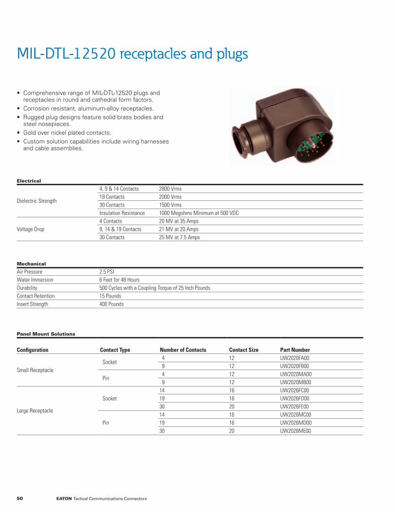
• Comprehensive range of MIL-DTL-12520 plugs and receptacles in round and cathedral form factors.
• Corrosion resistant, aluminum-alloy receptacles. • Rugged plug designs feature solid brass bodies and steel nosepieces.
• Gold over nickel plated contacts. • Custom solution capabilities include wiring harnesses and cable assemblies.
MIL-DTL-12520 receptacles and plugs
Electrical
Dielectric Strength
4, 9 & 14 Contacts 2800 Vrms19 Contacts 2000 Vrms30 Contacts 1500 VrmsInsulation Resistance 1000 Megohms Minimum at 500 VDC
Voltage Drop4 Contacts 20 MV at 35 Amps9, 14 & 19 Contacts 21 MV at 20 Amps30 Contacts 25 MV at 7.5 Amps
Mechanical
Air Pressure 2.5 PSIWater Immersion 6 Feet for 48 HoursDurability 500 Cycles with a Coupling Torque of 25 Inch Pounds.Contact Retention 15 PoundsInsert Strength 400 Pounds
Panel Mount Solutions
Configuration Contact Type Number of Contacts Contact Size Part Number
Small ReceptacleSocket
4 12 UW2020FA009 12 UW2020FB00
Pin4 12 UW2020MA009 12 UW2020MB00
Large Receptacle
Socket14 16 UW2026FC0019 16 UW2026FD0030 20 UW2026FE00
Pin14 16 UW2026MC0019 16 UW2026MD0030 20 UW2026ME00
50 EATON Tactical Communications Connectors

MIL-DTL-12520 UW series
Cable Mount Solutions
ConfigurationContact Type
Number of Contacts
Contact Size
PartNumber
Round PlugSocket
4 12 UW1220FAXX9 12 UW1220FBXX
Pin4 12 UW1220MAXX9 12 UW1220MBXX
Small Cathedral PlugSocket
4 12 UW1320FAXX9 12 UW1320FBXX
Pin4 12 UW1320MAXX9 12 UW1320MBXX
Large Cathedral Plug
Socket14 16 UW1326FCXX19 16 UW1326FDXX30 20 UW1326FEXX
Pin14 16 UW1326MCXX19 16 UW1326MDXX30 20 UW1326MEXX
XX Value Cable Diameter (Inches)
11 0.292 to 0.34313 0.323 to 0.40615 0.386 to 0.48617 0.448 to 0.53119 0.511 to 0.59321 0.573 to 0.65623 0.636 to 0.71825 0.698 to 0.78127 0.761 to 0.843
A
H
E
F
J
K
D
C
B
1.46”(37.03mm)
2.00”(50.8mm)
Closed
0.72”(18.29mm)
1.56”(39.67mm)
0.63”(16 .00mm)
2.50”(63.50mm)
1.50”(38.1mm)
1.94”(49.28mm)
0.97”(24.64mm)
1.94” (49.28mm)CLOSED
Ø1.10”(Ø27.94mm)
M0
20
B C
2WU
A
A
D 00
1.18”(30.02mm)
1.47”(37.34mm)
DIA
Ø1.84”(46.84mm)
1.18”(29.85mm)
UW 1220 plug
UW2020MA00 receptacle
UW 1320 plug
UW2026FD00 receptacle
51EATON Tactical Communications Connectors

For additional tacom solutions information, please visit www.cooperinterconnect.com or call 805.484.0543
Eaton is a registered trademark.
All other trademarks are property of their respective owners.
Eaton1000 Eaton BoulevardCleveland, OH 44122United StatesEaton.com
© 2014 EatonAll Rights ReservedPrinted in USAPublication No. CA800001ENFebruary 2015