Embed Size (px)
Citation preview

1
Database Systems
Session 2 – Main Theme
Relational Data Model
& Relational Database Constraints
Dr. Jean-Claude Franchitti
New York University
Computer Science Department
Courant Institute of Mathematical Sciences
Presentation material partially based on textbook slides
Fundamentals of Database Systems (6th Edition)
by Ramez Elmasri and Shamkant Navathe
Slides copyright © 2015 and on slides produced by Zvi
Kedem copyight © 2014

2
Agenda
1 Session Overview
3 Summary and Conclusion
2 Relational Data Model & Database Constraints

3
Session Agenda
Session Overview
Relational Data Model & Database Constraints
Summary & Conclusion

4
What is the class about?
Course description and syllabus:
» http://www.nyu.edu/classes/jcf/CSCI-GA.2433-001
» http://cs.nyu.edu/courses/spring16/CSCI-GA.2433-001/
Textbooks: » Fundamentals of Database Systems (7th Edition)
Ramez Elmasri and Shamkant Navathe
Addition Wesley
ISBN-10: 0133970779, ISBN-13: 978-0133970777 7th Edition (06/18/15)

5
Icons / Metaphors
5
Common Realization
Information
Knowledge/Competency Pattern
Governance
Alignment
Solution Approach

6
Agenda
1 Session Overview
3 Summary and Conclusion
2 Relational Data Model & Database Constraints
7
Agenda
The need for database management systems
Brief overview of the relational model
Querying relational database directly and through views
Need for good logical design
Need for good physical design
Recovery
Concurrency
Layers of database management systems
Independence between/among layers
Various roles of designers, users, and maintainers

8
Two Main Functions Of Databases
A very large fraction of computer use is devoted to business
processing of data using databases
» Think about what Amazon has to do to manage its operations
Two main uses of databases
» OLTP (Online Transaction Processing)
The database is used is for entering, modifying, and querying data
Correctness, at least for entering and modifying data must be assured
Example: Amazon charges customer’s credit card for the price of the
book that a customer ordered
» OLAP (Online Analytical Processing)
The database is used for business intelligence, including data mining
The results do not have to be “completely correct,” as this may be too
inefficient to guarantee, but complex queries have to be answered
(relatively) fast
Example: Amazon wants to know how many books that cost less than
$10 each were sold in New Jersey during December 2009
9
Managing The Data Of An Enterprise
We may consider some enterprise (organization) and
the totality of the information it maintains.
We think about managing this information, focusing on
OLTP
Ideally, the information should be stored in a (logically)
single (possibly physically distributed) database system
We start with a very simple example to introduce some
concepts and issues to address
We look at only a very small part of information of the
type that an enterprise may need to keep
We need some way of describing sample data
We will think, in this unit, of the database as a set of
tables, each stored as a file on a disk

10
Agenda
The need for database management systems
Brief overview of the relational model
Querying relational database directly and through views
Need for good logical design
Need for good physical design
Recovery
Concurrency
Layers of database management systems
Independence between/among layers
Various roles of designers, users, and maintainers

11
The Relational Data Model
Relational model
First commercial implementations available in
early 1980s
Has been implemented in a large number of
commercial system
Hierarchical and network models
Preceded the relational model

12
Relational Model Concepts
The relational Model of Data is based on the
concept of a Relation
» The strength of the relational approach to data
management comes from the formal foundation
provided by the theory of relations
While we review the essentials of the formal
relational model here, there is a practical
standard model based on SQL, which will be
covered later in class as a language
Note: There are several important differences
between the formal model and the practical
model, as we shall see
13
Relational Model Concepts (continued)
A Relation is a mathematical concept based on
the ideas of sets
The model was first proposed by Dr. E.F. Codd of
IBM Research in 1970 in the following paper:
» "A Relational Model for Large Shared Data Banks,"
Communications of the ACM, June 1970
The above paper caused a major revolution in the
field of database management and earned Dr.
Codd the coveted ACM Turing Award

14
Informal Definitions
Informally, a relation looks like a table of values.
A relation typically contains a set of rows.
The data elements in each row represent certain facts that correspond to a real-world entity or relationship
» In the formal model, rows are called tuples
Each column has a column header that gives an indication of the meaning of the data items in that column
» In the formal model, the column header is called an attribute name (or just attribute)

15
Relational Model Concepts (cont’d.)

16
Informal Definitions
Key of a Relation:
» Each row has a value of a data item (or set of items)
that uniquely identifies that row in the table
• Called the key
» In the STUDENT table, SSN is the key
» Sometimes row-ids or sequential numbers are
assigned as keys to identify the rows in a table
• Called artificial key or surrogate key

17
Formal Definitions - Schema
The Schema (or description) of a Relation:
» Denoted by R(A1, A2, .....An)
» R is the name of the relation
» The attributes of the relation are A1, A2, ..., An
Example:
CUSTOMER (Cust-id, Cust-name, Address, Phone#)
» CUSTOMER is the relation name
» Defined over the four attributes: Cust-id, Cust-name,
Address, Phone#
Each attribute has a domain or a set of valid values.
» For example, the domain of Cust-id is 6 digit numbers.

18
Formal Definitions - Tuple
A tuple is an ordered set of values (enclosed in angled
brackets ‘< … >’)
Each value is derived from an appropriate domain.
A row in the CUSTOMER relation is a 4-tuple and would
consist of four values, for example:
» <632895, "John Smith", "101 Main St. Atlanta, GA 30332",
"(404) 894-2000">
» This is called a 4-tuple as it has 4 values
» A tuple (row) in the CUSTOMER relation.
A relation is a set of such tuples (rows)

19
Formal Definitions - Domain
A domain has a logical definition:
» Example: “USA_phone_numbers” are the set of 10 digit phone numbers valid in the U.S.
A domain also has a data-type or a format defined for it.
» The USA_phone_numbers may have a format: (ddd)ddd-dddd where each d is a decimal digit.
» Dates have various formats such as year, month, date formatted as yyyy-mm-dd, or as dd mm,yyyy etc.
The attribute name designates the role played by a domain in a relation:
» Used to interpret the meaning of the data elements corresponding to that attribute
» Example: The domain Date may be used to define two attributes named “Invoice-date” and “Payment-date” with different meanings

20
Formal Definitions - State
The relation state is a subset of the Cartesian product of the domains of its attributes
» each domain contains the set of all possible values the attribute can take.
Example: attribute Cust-name is defined over the domain of character strings of maximum length 25
» dom(Cust-name) is varchar(25)
The role these strings play in the CUSTOMER relation is that of the name of a customer.

21
Meaning of a Relation
Interpretation (meaning) of a relation
Assertion
• Each tuple in the relation is a fact or a particular
instance of the assertion
Predicate
• Values in each tuple interpreted as values that
satisfy predicate

22
Relational Model Notation
Relation schema R of degree n
Denoted by R(A1, A2, ..., An)
Uppercase letters Q, R, S
Denote relation names
Lowercase letters q, r, s
Denote relation states
Letters t, u, v
Denote tuples
23
Formal Definitions - Summary
Formally,
» Given R(A1, A2, .........., An)
» r(R) dom (A1) X dom (A2) X ....X dom(An)
R(A1, A2, …, An) is the schema of the relation
R is the name of the relation
A1, A2, …, An are the attributes of the relation
r(R): a specific state (or "value" or “population”)
of relation R – this is a set of tuples (rows)
» r(R) = {t1, t2, …, tn} where each ti is an n-tuple
» ti = <v1, v2, …, vn> where each vj element-of dom(Aj)

24
Formal Definitions - Example
Let R(A1, A2) be a relation schema:
» Let dom(A1) = {0,1}
» Let dom(A2) = {a,b,c}
Then: dom(A1) X dom(A2) is all possible
combinations:
{<0,a> , <0,b> , <0,c>, <1,a>, <1,b>, <1,c> }
The relation state r(R) dom(A1) X dom(A2)
For example: r(R) could be {<0,a> , <0,b> , <1,c> }
» this is one possible state (or “population” or “extension”)
r of the relation R, defined over A1 and A2.
» It has three 2-tuples: <0,a> , <0,b> , <1,c>

25
Definition Summary
Informal Terms Formal Terms
Table Relation
Column Header Attribute
All possible Column
Values
Domain
Row Tuple
Table Definition Schema of a Relation
Populated Table State of the Relation

26
Example – A Relation STUDENT

27
Characteristics of Relations
Ordering of tuples in a relation r(R):
» The tuples are not considered to be ordered, even though they appear to be in the tabular form.
Ordering of attributes in a relation schema R (and of values within each tuple):
» We will consider the attributes in R(A1, A2, ..., An) and the values in t=<v1, v2, ..., vn> to be ordered .
• (However, a more general alternative definition of relation does not require this ordering. It includes both the name and the value for each of the attributes ).
• Example: t= { <name, “John” >, <SSN, 123456789> }
• This representation may be called as “self-describing”.

28
Same State as Previous Figure but Different Order of Tuples

29
Characteristics of Relations (continued)
Values in a tuple:
» All values are considered atomic (indivisible).
» Each value in a tuple must be from the domain
of the attribute for that column
• If tuple t = <v1, v2, …, vn> is a tuple (row) in the
relation state r of R(A1, A2, …, An)
• Then each vi must be a value from dom(Ai)
» A special null value is used to represent values
that are unknown or not available or
inapplicable in certain tuples.

30
Characteristics of Relations (continued)
Notation:
» We refer to component values of a tuple t by:
• t[Ai] or t.Ai
• This is the value vi of attribute Ai for tuple t
» Similarly, t[Au, Av, ..., Aw] refers to the
subtuple of t containing the values of attributes
Au, Av, ..., Aw, respectively in t

31
Characteristics of Relations (continued)
Values and NULLs in tuples
Each value in a tuple is atomic
Flat relational model
• Composite and multivalued attributes not allowed
• First normal form assumption
Multivalued attributes
• Must be represented by separate relations
Composite attributes
• Represented only by simple component attributes in
basic relational model

32
Characteristics of Relations (continued)
NULL values
Represent the values of attributes that may be
unknown or may not apply to a tuple
Meanings for NULL values
• Value unknown
• Value exists but is not available
• Attribute does not apply to this tuple (also known as
value undefined)

33
A Sample Relational Database
Of course, the values do not pretend to be real, they were
chosen to be short, so can be easily fitted on the slide
The database talks about employees, books they have checked out from the library (and when), and various illnesses they have had (and when)
SSN City DOB
101 Boston 3498
106 London 2987
121 Portland 2367
132 Miami 3678
Name SSN DOB Grad
e
Salar
y
A 121 2367 2 80
A 132 3678 3 70
B 101 3498 4 70
C 106 2987 2 80
SSN Book Date
132 Plants 8976
121 Anim
als
9003
SSN Illness Date
101 Cold 3498
121 Flu 2987

34
Agenda
The need for database management systems
Brief overview of the relational model
Querying relational database directly and through views
Need for good logical design
Need for good physical design
Recovery
Concurrency
Layers of database management systems
Independence between/among layers
Various roles of designers, users, and maintainers
35
Some Typical Queries
Some typical queries
» Give Name of every employee born before 3500
» Give Name and City for every employee who took out a Book after
9000
» Prepare a recall notice to for every employee who had a flu to come for
a checkup
Note that some queries involve a single table, and some
involve several tables
We would like to have a convenient language, as close as possible
to a natural language, to express these queries, and similar ones,
thinking of tables, not of lower-level structures (files)
Some languages
» SQL (used to be called Structured Query Language): every relational
database supports some “close to standard” version
» QBE (Query By Example); underlying, e.g., Microsoft Access’s GUI

36
Two Queries in SQL
Imagine that the tables are have names (as they of course do in
SQL)
» Table1: with columns SSN, City, DOB
» Table2: with columns Name, SSN, DOB, Grade, Salary
» Table3: with columns SSN, Book, Date
» Table4: with columns SSN, Illness, date
Give Name of every employee born before 3500
SELECT Name
FROM Table2
WHERE DOB < 3500;
Give Name and City for every employee who took out a Book after
9000
SELECT Name, City
FROM Table2, Table 1
WHERE Table2.SSN = Table1.SSN;

37
Agenda
The need for database management systems
Brief overview of the relational model
Querying relational database directly and through views
Need for good logical design
Need for good physical design
Recovery
Concurrency
Layers of database management systems
Independence between/among layers
Various roles of designers, users, and maintainers
38
The Need For Good Design
It is important also to think carefully about the correct (or
just good!) choice of which tables to use and what
should be their structure
This we should do in order to have good logical design,
not worrying (yet) about efficient storage in files
Our initial design suffers (for pedagogical reasons) from
various problems, which we will see next

39
Redundancy
A data item appears more than once unnecessarily
» Assuming that each SSN has only one DOB, DOB appears twice
unnecessarily (in two different tables)
There is a danger that this will be inconsistent
» Even more dangerous would have been multiple storage of employee’s
City
If the employee moves, the City must be changed everywhere it
appears
Note, however, that from an efficiency point of view, it might be
useful to replicate information, to speed up access
» In our example, if frequently we want to correlate DOB with Grade and
also DOB with City, it may be good to have it in both tables, and not
insist on a “clean” design
Note that it was necessary for SSN to appear in two different
tables, as otherwise we could not “assemble” information about
employees

40
Relational Model Constraints
Constraints determine which values are permissible and
which are not in the database.
They are of three main types:
1. Inherent or Implicit Constraints: These are based on
the data model itself. (E.g., relational model does not allow a
list as a value for any attribute)
2. Schema-based or Explicit Constraints: They are
expressed in the schema by using the facilities provided by
the model. (E.g., max. cardinality ratio constraint in the ER
model)
3. Application based or semantic constraints: These are
beyond the expressive power of the model and must be
specified and enforced by the application programs.

41
Relational Integrity Constraints
Constraints are conditions that must hold on all valid
relation states.
There are three main types of (explicit schema-based)
constraints that can be expressed in the relational model:
» Key constraints
» Entity integrity constraints
» Referential integrity constraints
Another schema-based constraint is the domain
constraint
» Every value in a tuple must be from the domain of its
attribute (or it could be null, if allowed for that attribute)

42
Key Constraints
Superkey of R:
» Is a set of attributes SK of R with the following condition:
• No two tuples in any valid relation state r(R) will have the same
value for SK
• That is, for any distinct tuples t1 and t2 in r(R), t1[SK] t2[SK]
• This condition must hold in any valid state r(R)
Key of R:
» A "minimal" superkey
» That is, a key is a superkey K such that removal of any
attribute from K results in a set of attributes that is not a
superkey (does not possess the superkey uniqueness
property)
A Key is a Superkey but not vice versa

43
Key Constraints (continued)
Example: Consider the CAR relation schema:
» CAR(State, Reg#, SerialNo, Make, Model, Year)
» CAR has two keys:
• Key1 = {State, Reg#}
• Key2 = {SerialNo}
» Both are also superkeys of CAR
» {SerialNo, Make} is a superkey but not a key.
In general:
» Any key is a superkey (but not vice versa)
» Any set of attributes that includes a key is a superkey
» A minimal superkey is also a key

44
Key Constraints (continued)
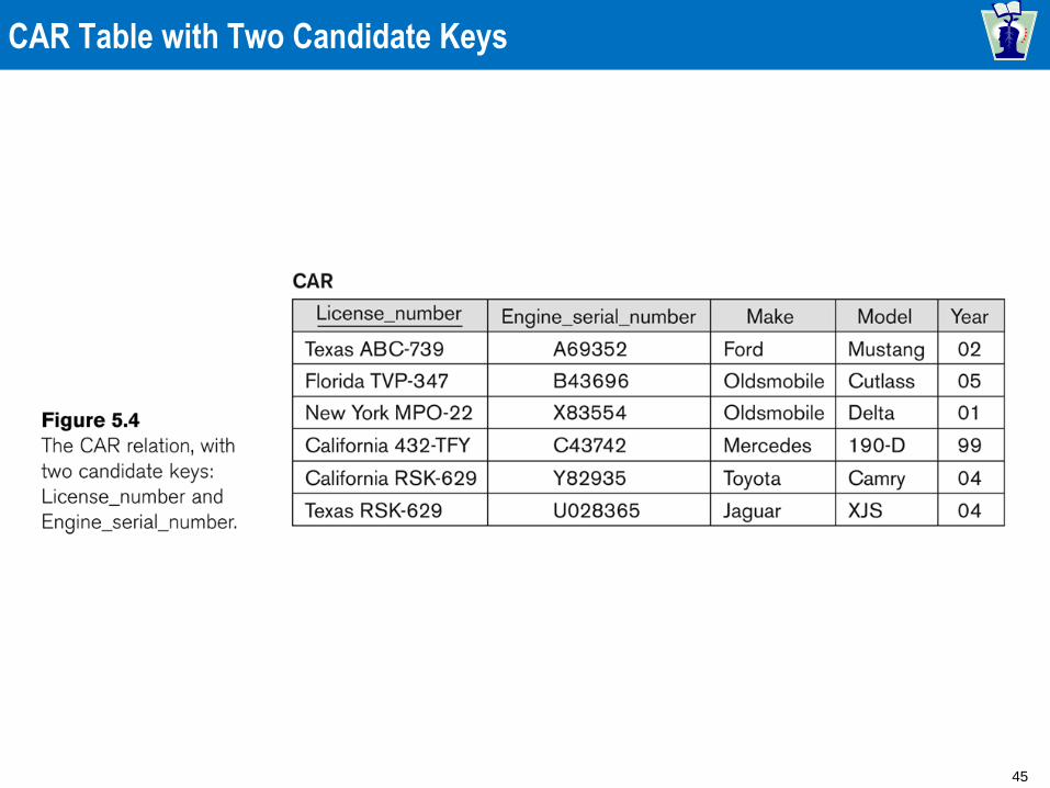
If a relation has several candidate keys, one is chosen arbitrarily to be the primary key. » The primary key attributes are underlined.
Example: Consider the CAR relation schema: » CAR(State, Reg#, SerialNo, Make, Model, Year)
» We chose SerialNo as the primary key
The primary key value is used to uniquely identify each tuple in a relation » Provides the tuple identity
Also used to reference the tuple from another tuple » General rule: Choose as primary key the smallest of the
candidate keys (in terms of size)
» Not always applicable – choice is sometimes subjective
45
CAR Table with Two Candidate Keys

46
Relational Database Schema
Relational Database Schema:
» A set S of relation schemas that belong to the
same database.
» S is the name of the whole database schema
» S = {R1, R2, ..., Rn} and a set IC of integrity
constraints.
» R1, R2, …, Rn are the names of the individual
relation schemas within the database S
Following slide shows a COMPANY
database schema with 6 relation schemas

47
COMPANY Database Schema

48
Relational Database State
A relational database state DB of S is a set of
relation states DB = {r1, r2, ..., rm} such that each ri
is a state of Ri and such that the ri relation states
satisfy the integrity constraints specified in IC.
A relational database state is sometimes called a
relational database snapshot or instance.
We will not use the term instance since it also
applies to single tuples.
A database state that does not meet the
constraints is an invalid state

49
Populated Database State
Each relation will have many tuples in its current relation
state
The relational database state is a union of all the
individual relation states
Whenever the database is changed, a new state arises
Basic operations for changing the database:
» INSERT a new tuple in a relation
» DELETE an existing tuple from a relation
» MODIFY an attribute of an existing tuple
Next slide shows an example state for the COMPANY
database schema shown in Fig. 5.5.

50
Populated Database State for COMPANY Database Schema

51
Entity Integrity
Entity Integrity:
» The primary key attributes PK of each relation schema
R in S cannot have null values in any tuple of r(R).
• This is because primary key values are used to identify the
individual tuples.
• t[PK] null for any tuple t in r(R)
• If PK has several attributes, null is not allowed in any of these
attributes
» Note: Other attributes of R may be constrained to
disallow null values, even though they are not
members of the primary key.

52
Referential Integrity
A constraint involving two relations
» The previous constraints involve a single
relation.
Used to specify a relationship among
tuples in two relations:
» The referencing relation and the referenced
relation.

53
Referential Integrity (continued)
Tuples in the referencing relation R1 have
attributes FK (called foreign key attributes)
that reference the primary key attributes PK
of the referenced relation R2.
» A tuple t1 in R1 is said to reference a tuple t2
in R2 if t1[FK] = t2[PK].
A referential integrity constraint can be
displayed in a relational database schema
as a directed arc from R1.FK to R2.

54
Referential Integrity (or Foreign Key) Constraint
Statement of the constraint
» The value in the foreign key column (or
columns) FK of the the referencing relation
R1 can be either:
• (1) a value of an existing primary key value of a
corresponding primary key PK in the referenced
relation R2, or
• (2) a null.
In case (2), the FK in R1 should not be a
part of its own primary key.

55
Displaying a Relational Database Schema and its Constraints
Each relation schema can be displayed as a row of attribute names
The name of the relation is written above the attribute names
The primary key attribute (or attributes) will be underlined
A foreign key (referential integrity) constraints is displayed as a directed arc (arrow) from the foreign key attributes to the referenced table
» Can also point the the primary key of the referenced relation for clarity
Next slide shows the COMPANY relational schema diagram with referential integrity constraints

56
Referential Integrity Constraints for COMPANY Database

57
Other Types of Constraints
Semantic Integrity Constraints:
» based on application semantics and cannot be
expressed by the model per se
» Example: “the max. no. of hours per employee for all
projects he or she works on is 56 hrs per week”
A constraint specification language may have to be
used to express these
SQL-99 allows CREATE TRIGGER and CREATE
ASSERTION to express some of these semantic
constraints
Keys, Permissibility of Null values, Candidate Keys
(Unique in SQL), Foreign Keys, Referential Integrity etc.
are expressed by the CREATE TABLE statement in SQL.

58
Other Types of Constraints (continued)
Functional dependency constraint
Establishes a functional relationship among
two sets of attributes X and Y
Value of X determines a unique value of Y
State constraints
Define the constraints that a valid state of the
database must satisfy
Transition constraints
Define to deal with state changes in the
database

59
Storage Of Constraints (aka., “Business Rules”)
Assume that it is the policy of our enterprise that the value of Salary
is determined only by the value of Grade; this is an example of a
business rule
» Thus the fact that the Grade = 2 implies Salary = 80 is written twice in
the database
» This is another type of redundancy, which is less obvious at first
There are additional problems with this design.
» We are unable to store the salary structure for a Grade that does not
currently exist for any employee.
» For example, we cannot store that Grade = 1 implies Salary = 90
» For example, if employee with SSN = 132 leaves, we forget which
Salary should be paid to employee with Grade = 3
» We could perhaps invent a fake employee with such a Grade and such
a Salary, but this brings up additional problems, e.g.,
What is the SSN of such a fake employee?
Note that our constraints specify a pay scale, which is independent
of a particular employee
60
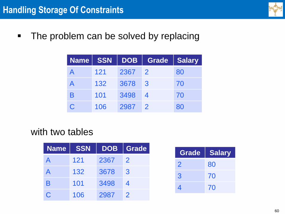
Handling Storage Of Constraints
The problem can be solved by replacing
with two tables
Name SSN DOB Grade Salary
A 121 2367 2 80
A 132 3678 3 70
B 101 3498 4 70
C 106 2987 2 80
Name SSN DOB Grade
A 121 2367 2
A 132 3678 3
B 101 3498 4
C 106 2987 2
Grade Salary
2 80
3 70
4 70

61
Handling Storage Of Constraints
And now we can store information more naturally
» We can specify that Grade 3 implies Salary 70, even after the
only employee with this Grade, i.e., employee with SSN 132 left
the enterprise
» We can specify that Grade 1 (a new Grade just established)
implies Salary 90, even before any employee with this grade is
higher
Name SSN DOB Grade
A 121 2367 2
B 101 3498 4
C 106 2987 2
Grade Salary
1 90
2 80
3 70
4 70

62
Clean Design Versus Efficiency
However, if the correlation between an employee and
salary is needed frequently, e.g., for producing payroll, it
may be inefficient to recompute this correlation
repeatedly.
So, returning to our original instance of the database,
perhaps we should have (despite some redundancy)
both the original table and the table associating salaries
with grades
Name SSN DOB Grade Salary
A 121 2367 2 80
A 132 3678 3 70
B 101 3498 4 70
C 106 2987 2 80
Grade Salary
2 80
3 70
4 70

63
Sample Database State

64
Sample Database State (cont’d)

65
Sample Referential Integrity Constraints

66
One More Problem
What if it becomes illegal to use social security numbers
for anything other than payroll related matters?
We will have an incredible mess and enormous amount
of work to restructure the database, unless we have
designed the application appropriately to begin with
Of course we did not know that it would become illegal
to use social security numbers and it was convenient to
do so, so that’s what we used
So how to be able to anticipate potential problems?
NYU had to spend considerable effort to switch from
social security numbers to University ID’s
We will discuss how to “anticipate” such problems, so
such switching is painless

67
Update Operations on Relations
INSERT a tuple.
DELETE a tuple.
MODIFY a tuple.
Integrity constraints should not be violated
by the update operations.
Several update operations may have to be
grouped together.
Updates may propagate to cause other
updates automatically. This may be
necessary to maintain integrity constraints.

68
Update Operations on Relations (continued)
In case of integrity violation, several actions
can be taken:
» Cancel the operation that causes the violation
(RESTRICT or REJECT option)
» Perform the operation but inform the user of
the violation
» Trigger additional updates so the violation is
corrected (CASCADE option, SET NULL
option)
» Execute a user-specified error-correction
routine

69
Possible Violations for Insert Operation
INSERT may violate any of the constraints:
» Domain constraint:
• if one of the attribute values provided for the new tuple is not of
the specified attribute domain
» Key constraint:
• if the value of a key attribute in the new tuple already exists in
another tuple in the relation
» Referential integrity:
• if a foreign key value in the new tuple references a primary key
value that does not exist in the referenced relation
» Entity integrity:
• if the primary key value is null in the new tuple

70
Possible Violations for Delete Operation
DELETE may violate only referential integrity:
» If the primary key value of the tuple being deleted is
referenced from other tuples in the database
• Can be remedied by several actions: RESTRICT, CASCADE,
SET NULL (see Chapter 6 for more details)
– RESTRICT option: reject the deletion
– CASCADE option: propagate the new primary key value into the
foreign keys of the referencing tuples
– SET NULL option: set the foreign keys of the referencing tuples
to NULL
» One of the above options must be specified during database
design for each foreign key constraint

71
Possible Violations for Update Operation
UPDATE may violate domain constraint and NOT NULL
constraint on an attribute being modified
Any of the other constraints may also be violated,
depending on the attribute being updated:
» Updating the primary key (PK):
• Similar to a DELETE followed by an INSERT
• Need to specify similar options to DELETE
» Updating a foreign key (FK):
• May violate referential integrity
» Updating an ordinary attribute (neither PK nor FK):
• Can only violate domain constraints

72
Different Users Need Different Data
It may be our goal to create a design that best reflects the inherent
properties of the data.
» But, various user groups may need to look at the data assuming
different structure (organization) of the data
For privacy/security reasons we may want to give different users
different access privileges to the database
» The payroll department can see salaries but cannot see diseases.
» The health department can see diseases but cannot see salaries.
Users may prefer to look at different aspects of the information.
» The payroll department may prefer to see the salary in a different
currency
» The health department may prefer to see Age instead of, or in addition
to DOB

73
Views
A possible solution: give each user (class of users) privileges to look
at a view, that is, a small derived database
The health department may think that there is a table:
The database should provide such a view, which is computed from
the existing tables (and the current date), without the user knowing
other (prohibited for this user) information
We need to leave flexibility for unanticipated queries.
» Some people may later be given the right and want to ask the query:
“How are salaries and diseases correlated?”
Name SSN City DOB Ag
e
Illnes
s
Date
A 121 Portland 2367 47 Flu 2987
B 101 Boston 3498 25 Cold 3498

74
Manipulating Data Through Views
The ideal goal is for the users to both query and modify
the database through views
Unfortunately, sometimes it impossible or difficult to do
so
» If the user wants to change the age of an employee, how should
the change be reflected in the date of birth?
There is no unique way of doing it
» How to change the sum of salaries, if some view contains this
information?
We want to give a total raise of 5% (increase sum of salaries by
5%), so how to reflect this in individual salaries?
Some employees may get more than 5% and some may get
less than 5%

75
Agenda
The need for database management systems
Brief overview of the relational model
Querying relational database directly and through views
Need for good logical design
Need for good physical design
Recovery
Concurrency
Layers of database management systems
Independence between/among layers
Various roles of designers, users, and maintainers

76
Physical Design
The database system must be organized so that it is
able to process queries efficiently
To do this:
» Files must be organized appropriately
» Indices may be employed
For example, if we frequently want to find the grade for
various SSN, perhaps the file should be hashed on this
value, allowing direct access
But, if we want to print the salaries of all the employees
born in 2783, maybe the file should be sorted by DOB
Physical design of databases deals with such issues
(including how to distribute information among various
sites), which are also closely related to the optimization
of query processing

77
Agenda
The need for database management systems
Brief overview of the relational model
Querying relational database directly and through views
Need for good logical design
Need for good physical design
Recovery
Concurrency
Layers of database management systems
Independence between/among layers
Various roles of designers, users, and maintainers

78
Recovery
The database must be resilient even though the system
is prone to faults.
Assume one more table, describing employees'
accounts in the credit union
We want to give each employee a bonus of 10 in the
savings account.
» To do that, a transaction (execution of a user program) will
sequentially change the values of Savings
SSN Savings Checking
101 40 30
106 40 20
121 0 80
132 10 0

79
Example Of A Problem
The file describing the table is stored on a disk, values are read into
RAM, modified and written out
If X is a local variable then we have a trace of the desired execution
(in shorthand):
.
X := Savings[101] read from disk
X := X + 10 process in RAM
Savings[101] := X write to disk
.
What if the system crashes in the middle, say power goes out
We do not know which of the values have been changed, so what
to do to recover (get back a correct state)?
Various techniques exist for managing the execution, so that
reliable execution is possible

80
Agenda
The need for database management systems
Brief overview of the relational model
Querying relational database directly and through views
Need for good logical design
Need for good physical design
Recovery
Concurrency
Layers of database management systems
Independence between/among layers
Various roles of designers, users, and maintainers
81
Concurrency
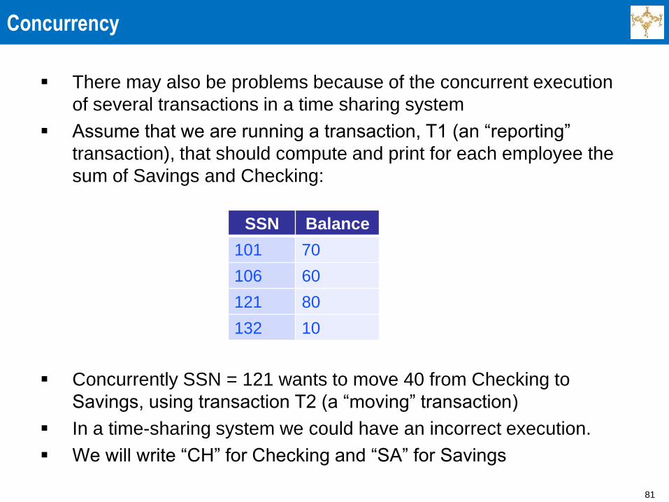
There may also be problems because of the concurrent execution
of several transactions in a time sharing system
Assume that we are running a transaction, T1 (an “reporting”
transaction), that should compute and print for each employee the
sum of Savings and Checking:
Concurrently SSN = 121 wants to move 40 from Checking to
Savings, using transaction T2 (a “moving” transaction)
In a time-sharing system we could have an incorrect execution.
We will write “CH” for Checking and “SA” for Savings
SSN Balance
101 70
106 60
121 80
132 10

82
The Transaction Concept
Transaction
Executing program
Includes some database operations
Must leave the database in a valid or
consistent state
Online transaction processing (OLTP)
systems
Execute transactions at rates that reach
several hundred per second
83
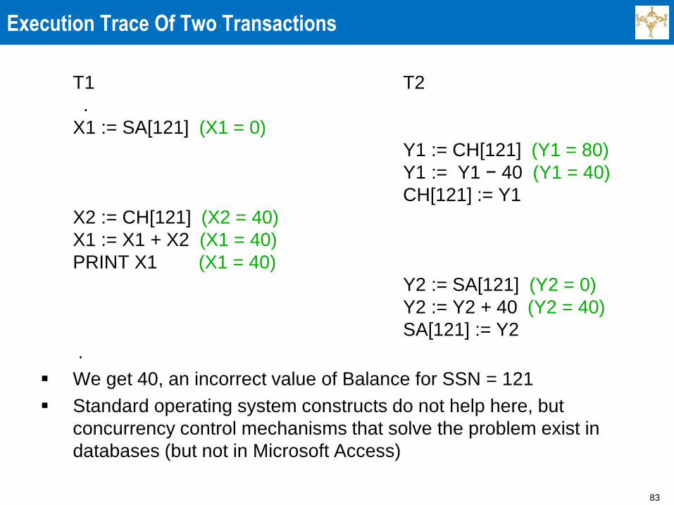
Execution Trace Of Two Transactions
T1 T2
.
X1 := SA[121] (X1 = 0)
Y1 := CH[121] (Y1 = 80)
Y1 := Y1 − 40 (Y1 = 40)
CH[121] := Y1
X2 := CH[121] (X2 = 40)
X1 := X1 + X2 (X1 = 40)
PRINT X1 (X1 = 40)
Y2 := SA[121] (Y2 = 0)
Y2 := Y2 + 40 (Y2 = 40)
SA[121] := Y2
.
We get 40, an incorrect value of Balance for SSN = 121
Standard operating system constructs do not help here, but
concurrency control mechanisms that solve the problem exist in
databases (but not in Microsoft Access)

84
Some Concurrency Aspects
In the previous examples, we could allow the two
transactions to interleave in this way, with the user of
the “reporting” transaction being told that correct results
are not guaranteed
The user may get only approximate result, which
perhaps is sufficient if we are producing “statistical”
reports
But the database will remain consistent (correct) and
the “moving” transaction can execute
But if instead of the “reporting” transaction which only
read the database, we have a “multiplying” transaction
that updates all the values in the database by
multiplying them by 2, then the database could be
corrupted, and the interleaving cannot be permitted
85
Agenda
The need for database management systems
Brief overview of the relational model
Querying relational database directly and through views
Need for good logical design
Need for good physical design
Recovery
Concurrency
Layers of database management systems
Independence between/among layers
Various roles of designers, users, and maintainers

86
The Layers/Levels Of The Ideal Database
It is customary to think of the database as made of several layers or
levels, which are not completely standardized
Different levels have different roles
We will think of 4 levels:
» External (User) Various user views
» Conceptual (Community) Description of the enterprise
» Internal (Physical) Files, access methods,
indices, distribution
» Database O.S. Recovery and concurrency
The database, does not run on a bare machine
The Database O.S. (DBOS) runs on top of the O.S., such as
Windows or Linux

87
The Conceptual Level
The conceptual level is most fundamental as it
describes the total information and its structure/meaning
» to the extent we understand the information and know how to
express our understanding
It is also generally used for manipulating the database,
that is querying and modifying it
The tools we have:
» Data Definition Language (DDL), for description
» Data Manipulation Language (DML), for querying and
modifying
Tables in our example (their structure, not the specific
values which change in time) were a kind of DDL
» They form a schema, a description of the structure.
Of course, this level changes as the needs of the
enterprise change

88
The External Level
The external level is seen by various users.
Each view (subschema) is like a small conceptual level.
It can also change in time.
A particular view may be modified, deleted, or added
even if the conceptual level does not change
» For example, it may become illegal for some user to see some
information

89
The Internal Level
The internal level deals with file organization/storage
management
It changes in time too
» New storage devices are brought
» Files may have indices created because some queries have
become more frequent
» The data may be geographically distributed

90
The Data Base Operating System Level
The data base operating system level deals with
concurrency and recovery
The data base operating system can change too
The vendor of the data base may discover better
methods to handle recovery/concurrency

91
Agenda
The need for database management systems
Brief overview of the relational model
Querying relational database directly and through views
Need for good logical design
Need for good physical design
Recovery
Concurrency
Layers of database management systems
Independence between/among layers
Various roles of designers, users, and maintainers

92
Independence Among Levels
A very important goal is (Data-) independence
between/among levels
We must make sure that changes in one level disturb as
little as possible the other levels (propagate as little as
possible)

93
Agenda
The need for database management systems
Brief overview of the relational model
Querying relational database directly and through views
Need for good logical design
Need for good physical design
Recovery
Concurrency
Layers of database management systems
Independence between/among layers
Various roles of designers, users, and maintainers

94
Who Does What?
The vendor sends:
» The database operating system
» Tools to create and manipulate the three top levels: external,
conceptual, and internal
The database administrator (DBA) and his/her staff
discuss with the users what information the database
should contain and its structure
» A common model (language for describing reality) is needed for
them to communicate
Entity-relationship model is frequently used
The DBA and the users design the conceptual and the
external levels

95
Design And Management Of The System
During the actual design the database administrator uses a specific
data model and a specific DDL (a completely precise way of
describing the data)
» Now, it is usually relational
» Previously hierarchical and network models were popular
» In the future, perhaps object-oriented (some in use)
The database administrator and the users write programs in DML to
access and manipulate the database
The database administrator maintains the internal level changing it
depending on changing applications and equipment
The database administrator makes backups, arranges for recovery,
etc
The above description is idealized
96
Challenges
We have seen just the tip of the iceberg of what needs
to happen for database systems to function as required
We need
» Natural semantics
» Convenient syntax
» Efficiency
» 100% reliability
Enormous effort has been spent since mid 70s to
achieve this

97
Agenda
1 Session Overview
3 Summary and Conclusion
2 Relational Data Model & Database Constraints

98
Summary
Presented Relational Model Concepts
» Definitions
» Characteristics of relations
Discussed Relational Model Constraints and Relational
Database Schemas
» Domain constraints
» Key constraints
» Entity integrity
» Referential integrity
Described the Relational Update Operations and Dealing
with Constraint Violations
99
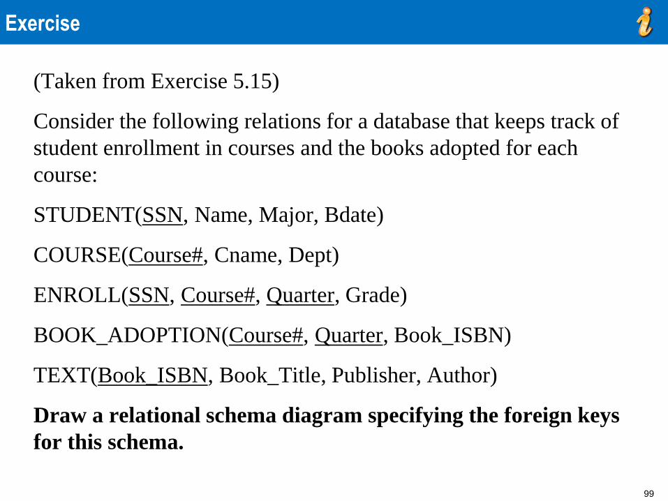
Exercise
(Taken from Exercise 5.15)
Consider the following relations for a database that keeps track of
student enrollment in courses and the books adopted for each
course:
STUDENT(SSN, Name, Major, Bdate)
COURSE(Course#, Cname, Dept)
ENROLL(SSN, Course#, Quarter, Grade)
BOOK_ADOPTION(Course#, Quarter, Book_ISBN)
TEXT(Book_ISBN, Book_Title, Publisher, Author)
Draw a relational schema diagram specifying the foreign keys
for this schema.

100
Assignments & Readings
Readings
» Slides and Handouts posted on the course web site
» Textbook: Chapter 5
Assignment #2
» Textbook exercises: 1.9, 1.12, 2.14, 2.15, 5.16, 5.18, 5.20
Project Framework Setup
» TBD

101
Next Session: - Data Modeling Using ER Model
- Relational Design via ER/EER to Relational Mapping

102
Any Questions?