Embed Size (px)
Citation preview
Datacard® CD800™ Card Printer
Installation and Administrator’s Guide
January 2017
Part No. 527444-001, Rev. E

NoticePlease do not attempt to operate or repair this equipment without adequate training.
Any use, operation or repair you perform that is not in accordance with the information
contained in this documentation is at your own risk.
Trademark AcknowledgmentsDatacard is a registered trademark and service mark of Entrust Datacard Corporation in
the United States and other countries.
Entrust is a registered trademark and service mark in the United States and other
countries.
MasterCard is a registered trademark of MasterCard International Incorporated.
Visa is a registered trademark of Visa International Service Association.
All other product names are the property of their respective owners.
Proprietary NoticeThe design and information contained in these materials are protected by US and
international copyright laws.
All drawings and information herein are the property of Entrust Datacard Corporation. All
unauthorized use and reproduction is prohibited.
Entrust Datacard1187 Park PlaceShakopee, MN 55379Phone: 952-933-1223Fax: 952-933-7971
www.entrustdatacard.com
Copyright © 2014–2017 Entrust Datacard Corporation. All rights reserved.
ii

Compliance Statements Liability
The WARNING and CAUTION labels have been placed on the equipment for your safety. Please do
not attempt to operate or repair this equipment without adequate training. Any use, operation,
or repair in contravention of this document is at your own risk.
Safety The following basic safety tips are given to ensure safe installation, operation, and maintenance
of Entrust Datacard™ equipment.
• Connect equipment to a grounded power source. Do not defeat or bypass the ground lead.
• Place the equipment on a stable surface (table) and ensure floors in the work area are dry and
non-slip.
• Know the location of equipment branch circuit interrupters or circuit breakers and how to turn
them on and off in case of emergency.
• Know the location of fire extinguishers and how to use them. ABC type extinguishers may be
used on electrical fires.
• Know local procedures for first aid and emergency assistance at the customer facility.
• Use adequate lighting at the equipment location.
• Maintain the recommended temperature and humidity range in the equipment area.
iii

Regulatory ComplianceEMC Compliance Notice
To ensure compliance of the model RX10 retransfer printer to the radiated emissions
requirements for class “A” Information Technology Equipment, be sure to use a shielded Ethernet
cable when connecting to your network
Notice for USA (FCC Notice)
This equipment has been tested and found to comply with the limits for Class A computing
devices, pursuant to Part 15 of FCC rules. These limits are designed to provide reasonable
protection against harmful interference when the equipment is operated in a commercial
environment. This equipment generates, uses, and can radiate radio frequency energy. If this
equipment is not installed and used in accordance with this instruction manual, it may cause
harmful interference to radio communications. Operation of this equipment in a residential area
is likely to cause harmful interference in which case the user will be required to correct the
interference at their own expense. Changes or modifications not expressly approved by the party
responsible for compliance could void the user's authority to operate the equipment.
This device complies with Part 15 of the FCC Rules. Operation is subject to the following two
conditions: (1) This device may not cause harmful interference, and (2) this device must accept
any interference received, including interference that may cause undesired operation.
Notice for Canada
Industry Canada
This digital apparatus does not exceed the Class A limits for radio noise for digital apparatus set
out in the Radio Interference Regulations of the Canadian Department of Communications.
Le présent appareil numérique n'émet pas de bruits radioélectriques dépassant les limites
applicables aux appareils numériques de la classe A prescrites dans le Règlement sur le brouillage
radioélectrique édicté par le ministère des Communications du Canada.
RSS-Gen, Issue 3, December 2010, Section 7.1.3 User Manual Notice
This Device complies with Industry Canada License-exempt RSS standard(s). Operation is subject
to the following two conditions: 1) this device may not cause interference, and 2) this device
must accept any interference, including interference that may cause undesired operation of the
device.
Cet appareil est conforme avec Industrie Canada RSS standard exemptes de licence(s). Son
fonctionnement est soumis aux deux conditions suivantes: 1) ce dispositif ne peut causer des
interférences, et 2) cet appareil doit accepter toute interférence, y compris les interférences qui
peuvent causer un mauvais fonctionnement du dispositif.
iv

Notice for Europe
The EU Declaration of Conformity can be found on EntrustDatacard.com
WARNING: This is a class A product. This equipment is compliant with class A of either CISPR32 or
CISPR22. In a domestic/residential environment this equipment may cause radio interference, in
which case the user may be required to take adequate measures.
WEEE: The model RX10 retransfer printer uses a lithium coin cell battery. Refer to the service
manual for battery removal instructions.
Notice for Australia
This is a Class A product. In a domestic environment this product may cause radio interference, in
which case the user may be required to take adequate measures.
Notice for China (Simplified Chinese)
警告
此为 A级产品,在生活环境中,该产品可能会造成无线电干扰。在这种情况下,可能需要用户对干扰采取切实可行的措施。
Notice for Taiwan (Traditional Chinese)
Notice for Japan
Japanese Voluntary Control Council for Interference (VCCI) class A statement
v

Korea Communications Commission (KCC) statement
California Proposition 65 Compliance WARNING: This product contains chemicals, including lead, known to the State of California to
cause cancer, and birth defects or other reproductive harm. Wash hands after handling.
Entrust Datacard believes that its products are not harmful when used as designed. However, the
above warning is made in compliance with the State of California Safe Drinking Water and Toxic
Enforcement Act of 1986, which requires warning labels on products that may contain elements
that the State of California considers harmful.
California Lithium Perchlorate Warning
Perchlorate Material - special handling may apply. See www.dtsc.ca.gov/hazardouswaste/
perchlorate.
This notice is required by California Code of Regulations, Title 22, Division 4.5, Chapter 33: Best
Management Practices for Perchlorate Materials. This product/part includes a battery that
contains Perchlorate material.
vi
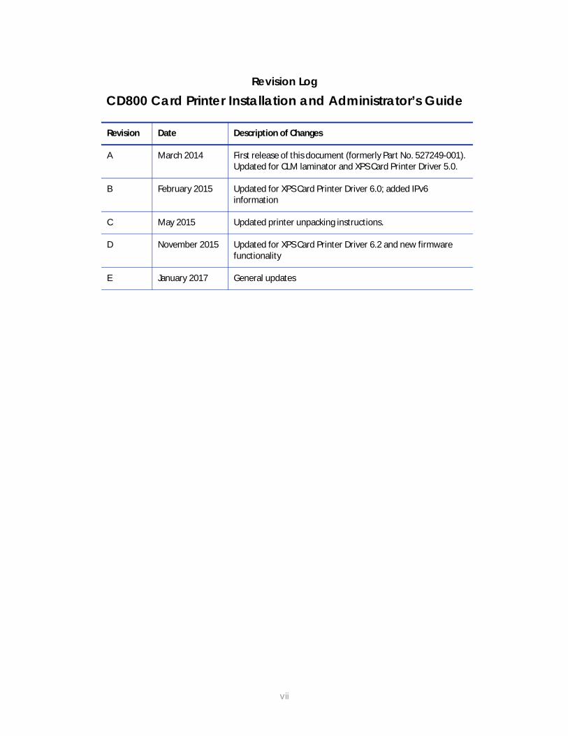
Revision LogCD800 Card Printer Installation and Administrator’s Guide
Revision Date Description of Changes
A March 2014 First release of this document (formerly Part No. 527249-001). Updated for CLM laminator and XPS Card Printer Driver 5.0.
B February 2015 Updated for XPS Card Printer Driver 6.0; added IPv6 information
C May 2015 Updated printer unpacking instructions.
D November 2015 Updated for XPS Card Printer Driver 6.2 and new firmware functionality
E January 2017 General updates
vii

viii
Contents
Chapter 1: Installation . . . . . . . . . . . . . . . . . . . . . . . . . . . . . . . . . . . . . . . . . . . . . . . . . . . . . . 1PC Requirements. . . . . . . . . . . . . . . . . . . . . . . . . . . . . . . . . . . . . . . . . . . . . . . . . . . . . . . . . . . . . . . 1Ethernet Requirements . . . . . . . . . . . . . . . . . . . . . . . . . . . . . . . . . . . . . . . . . . . . . . . . . . . . . . . . . . 2USB Requirements . . . . . . . . . . . . . . . . . . . . . . . . . . . . . . . . . . . . . . . . . . . . . . . . . . . . . . . . . . . . . . 2Electrical Requirements . . . . . . . . . . . . . . . . . . . . . . . . . . . . . . . . . . . . . . . . . . . . . . . . . . . . . . . . . 2Site Requirements . . . . . . . . . . . . . . . . . . . . . . . . . . . . . . . . . . . . . . . . . . . . . . . . . . . . . . . . . . . . . . 3
Printer Dimensions . . . . . . . . . . . . . . . . . . . . . . . . . . . . . . . . . . . . . . . . . . . . . . . . . . . . . . . . . . . 4Single-Hopper Printer . . . . . . . . . . . . . . . . . . . . . . . . . . . . . . . . . . . . . . . . . . . . . . . . . . . . . 4Printer with Optional Multi-Hopper . . . . . . . . . . . . . . . . . . . . . . . . . . . . . . . . . . . . . . . . . . 4
Clearance Requirements . . . . . . . . . . . . . . . . . . . . . . . . . . . . . . . . . . . . . . . . . . . . . . . . . . . . . 5Single-Hopper Printer . . . . . . . . . . . . . . . . . . . . . . . . . . . . . . . . . . . . . . . . . . . . . . . . . . . . . 5Printer with Optional Multi-Hopper . . . . . . . . . . . . . . . . . . . . . . . . . . . . . . . . . . . . . . . . . . 5
Secure Printing Requirements . . . . . . . . . . . . . . . . . . . . . . . . . . . . . . . . . . . . . . . . . . . . . . . . . . . . 6Set Up the Printer . . . . . . . . . . . . . . . . . . . . . . . . . . . . . . . . . . . . . . . . . . . . . . . . . . . . . . . . . . . . . . . 6
Prepare the Printer. . . . . . . . . . . . . . . . . . . . . . . . . . . . . . . . . . . . . . . . . . . . . . . . . . . . . . . . . . . 7Remove Packing Material From the Printer . . . . . . . . . . . . . . . . . . . . . . . . . . . . . . . . . . . 7Load Cards . . . . . . . . . . . . . . . . . . . . . . . . . . . . . . . . . . . . . . . . . . . . . . . . . . . . . . . . . . . . . 9Load the Print Ribbon . . . . . . . . . . . . . . . . . . . . . . . . . . . . . . . . . . . . . . . . . . . . . . . . . . . . 10Load the Cleaning Sleeve . . . . . . . . . . . . . . . . . . . . . . . . . . . . . . . . . . . . . . . . . . . . . . . . 11Install the Ribbon Cartridge . . . . . . . . . . . . . . . . . . . . . . . . . . . . . . . . . . . . . . . . . . . . . . . 11
Install Optional Equipment . . . . . . . . . . . . . . . . . . . . . . . . . . . . . . . . . . . . . . . . . . . . . . . . . . . 12Install a Large Output Hopper . . . . . . . . . . . . . . . . . . . . . . . . . . . . . . . . . . . . . . . . . . . . . 12Install the 200-Card Input Hopper . . . . . . . . . . . . . . . . . . . . . . . . . . . . . . . . . . . . . . . . . . 14Install the Optional Cable Lock. . . . . . . . . . . . . . . . . . . . . . . . . . . . . . . . . . . . . . . . . . . . 15
Connect the Printer to a Computer. . . . . . . . . . . . . . . . . . . . . . . . . . . . . . . . . . . . . . . . . . . . . . . 15Connect Using a USB Cable. . . . . . . . . . . . . . . . . . . . . . . . . . . . . . . . . . . . . . . . . . . . . . . . . . 15Connect Using a Network Cable . . . . . . . . . . . . . . . . . . . . . . . . . . . . . . . . . . . . . . . . . . . . . 16
Plug in and Power On the Printer . . . . . . . . . . . . . . . . . . . . . . . . . . . . . . . . . . . . . . . . . . . . . . . . . 16Use the Front Panel . . . . . . . . . . . . . . . . . . . . . . . . . . . . . . . . . . . . . . . . . . . . . . . . . . . . . . . . . . . . 17Configure the Printer. . . . . . . . . . . . . . . . . . . . . . . . . . . . . . . . . . . . . . . . . . . . . . . . . . . . . . . . . . . 18
Use IPv4 Addressing. . . . . . . . . . . . . . . . . . . . . . . . . . . . . . . . . . . . . . . . . . . . . . . . . . . . . . . . . 18 Set a Static IPv4 Address (Optional) . . . . . . . . . . . . . . . . . . . . . . . . . . . . . . . . . . . . . . . 18
Use IPv6 Addressing. . . . . . . . . . . . . . . . . . . . . . . . . . . . . . . . . . . . . . . . . . . . . . . . . . . . . . . . . 21Enable IPv6. . . . . . . . . . . . . . . . . . . . . . . . . . . . . . . . . . . . . . . . . . . . . . . . . . . . . . . . . . . . . 21Set a Manual IPv6 Address (Optional) . . . . . . . . . . . . . . . . . . . . . . . . . . . . . . . . . . . . . . 23
Test the IP Address Using a Local Network . . . . . . . . . . . . . . . . . . . . . . . . . . . . . . . . . . . . . . 25Use the Card Printer Driver . . . . . . . . . . . . . . . . . . . . . . . . . . . . . . . . . . . . . . . . . . . . . . . . . . . . . . 27Use OpenCard Data Format . . . . . . . . . . . . . . . . . . . . . . . . . . . . . . . . . . . . . . . . . . . . . . . . . . . . 27
ix
Chapter 2: Elements of Card Design . . . . . . . . . . . . . . . . . . . . . . . . . . . . . . . . . . . . . . . . . 29Basic Card Design. . . . . . . . . . . . . . . . . . . . . . . . . . . . . . . . . . . . . . . . . . . . . . . . . . . . . . . . . . . . . 29Printing Design . . . . . . . . . . . . . . . . . . . . . . . . . . . . . . . . . . . . . . . . . . . . . . . . . . . . . . . . . . . . . . . . 30
Color Printing . . . . . . . . . . . . . . . . . . . . . . . . . . . . . . . . . . . . . . . . . . . . . . . . . . . . . . . . . . . . . . 30Full-Panel Ribbon . . . . . . . . . . . . . . . . . . . . . . . . . . . . . . . . . . . . . . . . . . . . . . . . . . . . . . . . 30Short-Panel Ribbon . . . . . . . . . . . . . . . . . . . . . . . . . . . . . . . . . . . . . . . . . . . . . . . . . . . . . . 31Split-Ribbon Color Printing . . . . . . . . . . . . . . . . . . . . . . . . . . . . . . . . . . . . . . . . . . . . . . . . 31Manage Color . . . . . . . . . . . . . . . . . . . . . . . . . . . . . . . . . . . . . . . . . . . . . . . . . . . . . . . . . . 31Print Text in Color . . . . . . . . . . . . . . . . . . . . . . . . . . . . . . . . . . . . . . . . . . . . . . . . . . . . . . . . 31Print Graphics in Color . . . . . . . . . . . . . . . . . . . . . . . . . . . . . . . . . . . . . . . . . . . . . . . . . . . 32
Monochrome Printing . . . . . . . . . . . . . . . . . . . . . . . . . . . . . . . . . . . . . . . . . . . . . . . . . . . . . . . 32Monochrome Printing with Full-Color Ribbon. . . . . . . . . . . . . . . . . . . . . . . . . . . . . . . . . 32Monochrome Ribbon . . . . . . . . . . . . . . . . . . . . . . . . . . . . . . . . . . . . . . . . . . . . . . . . . . . . 33Ribbon Saver . . . . . . . . . . . . . . . . . . . . . . . . . . . . . . . . . . . . . . . . . . . . . . . . . . . . . . . . . . . 33Print Text in Monochrome. . . . . . . . . . . . . . . . . . . . . . . . . . . . . . . . . . . . . . . . . . . . . . . . . 33
Print Bar Codes . . . . . . . . . . . . . . . . . . . . . . . . . . . . . . . . . . . . . . . . . . . . . . . . . . . . . . . . . . . . . 34Bar Code Guidelines . . . . . . . . . . . . . . . . . . . . . . . . . . . . . . . . . . . . . . . . . . . . . . . . . . . . . 34Test Bar Codes . . . . . . . . . . . . . . . . . . . . . . . . . . . . . . . . . . . . . . . . . . . . . . . . . . . . . . . . . . 35Card Design Changes That Affect Bar Codes . . . . . . . . . . . . . . . . . . . . . . . . . . . . . . . . 36Print Bar Codes With the Card Printer Driver . . . . . . . . . . . . . . . . . . . . . . . . . . . . . . . . . 36
Apply Topcoat . . . . . . . . . . . . . . . . . . . . . . . . . . . . . . . . . . . . . . . . . . . . . . . . . . . . . . . . . . . . . 37Non-Printing Areas . . . . . . . . . . . . . . . . . . . . . . . . . . . . . . . . . . . . . . . . . . . . . . . . . . . . . . . . . . 37
Standard Magnetic Stripe Non-Printing Area . . . . . . . . . . . . . . . . . . . . . . . . . . . . . . . . 38Standard Smart Card Non-Printing Area . . . . . . . . . . . . . . . . . . . . . . . . . . . . . . . . . . . . 38Custom Non-Printing Areas . . . . . . . . . . . . . . . . . . . . . . . . . . . . . . . . . . . . . . . . . . . . . . . 38
Card Layout . . . . . . . . . . . . . . . . . . . . . . . . . . . . . . . . . . . . . . . . . . . . . . . . . . . . . . . . . . . . . . . 39Margins . . . . . . . . . . . . . . . . . . . . . . . . . . . . . . . . . . . . . . . . . . . . . . . . . . . . . . . . . . . . . . . . 39Backgrounds . . . . . . . . . . . . . . . . . . . . . . . . . . . . . . . . . . . . . . . . . . . . . . . . . . . . . . . . . . . 40Image Placement . . . . . . . . . . . . . . . . . . . . . . . . . . . . . . . . . . . . . . . . . . . . . . . . . . . . . . . 40
Magnetic Stripe Design. . . . . . . . . . . . . . . . . . . . . . . . . . . . . . . . . . . . . . . . . . . . . . . . . . . . . . . . . 41Magnetic Stripe Data Formats . . . . . . . . . . . . . . . . . . . . . . . . . . . . . . . . . . . . . . . . . . . . . . . 41
Three-Track Option (ISO/IAT) . . . . . . . . . . . . . . . . . . . . . . . . . . . . . . . . . . . . . . . . . . . . . . 41Single-Track Option (JIS) . . . . . . . . . . . . . . . . . . . . . . . . . . . . . . . . . . . . . . . . . . . . . . . . . . 42
Magnetic Stripe Coercivity . . . . . . . . . . . . . . . . . . . . . . . . . . . . . . . . . . . . . . . . . . . . . . . . . . . 43Smart Card Design . . . . . . . . . . . . . . . . . . . . . . . . . . . . . . . . . . . . . . . . . . . . . . . . . . . . . . . . . . . . 43
Smart Card Processing Requirements . . . . . . . . . . . . . . . . . . . . . . . . . . . . . . . . . . . . . . . . . . 43Smart Card Codes on the Printer Label . . . . . . . . . . . . . . . . . . . . . . . . . . . . . . . . . . . . . . . . 44Single-Wire Smart Card . . . . . . . . . . . . . . . . . . . . . . . . . . . . . . . . . . . . . . . . . . . . . . . . . . . . . . 45
Settings for Card Design in Printer Manager . . . . . . . . . . . . . . . . . . . . . . . . . . . . . . . . . . . . . . . 45
x
Chapter 3: Printer Manager . . . . . . . . . . . . . . . . . . . . . . . . . . . . . . . . . . . . . . . . . . . . . . . . 47Printer Manager . . . . . . . . . . . . . . . . . . . . . . . . . . . . . . . . . . . . . . . . . . . . . . . . . . . . . . . . . . . . . . 47
Printer Manager User Access Levels . . . . . . . . . . . . . . . . . . . . . . . . . . . . . . . . . . . . . . . . . . . 48WebUser . . . . . . . . . . . . . . . . . . . . . . . . . . . . . . . . . . . . . . . . . . . . . . . . . . . . . . . . . . . . . . . 48WebAdmin. . . . . . . . . . . . . . . . . . . . . . . . . . . . . . . . . . . . . . . . . . . . . . . . . . . . . . . . . . . . . 48WebService . . . . . . . . . . . . . . . . . . . . . . . . . . . . . . . . . . . . . . . . . . . . . . . . . . . . . . . . . . . . 48
Access Printer Manager . . . . . . . . . . . . . . . . . . . . . . . . . . . . . . . . . . . . . . . . . . . . . . . . . . . . . 48Printer Manager Settings. . . . . . . . . . . . . . . . . . . . . . . . . . . . . . . . . . . . . . . . . . . . . . . . . . . . . 51Print a Printer Manager Page. . . . . . . . . . . . . . . . . . . . . . . . . . . . . . . . . . . . . . . . . . . . . . . . . 51
Use Printer Manager . . . . . . . . . . . . . . . . . . . . . . . . . . . . . . . . . . . . . . . . . . . . . . . . . . . . . . . . . . . 51Status Menu . . . . . . . . . . . . . . . . . . . . . . . . . . . . . . . . . . . . . . . . . . . . . . . . . . . . . . . . . . . . . . . 52Printer Setting Menu . . . . . . . . . . . . . . . . . . . . . . . . . . . . . . . . . . . . . . . . . . . . . . . . . . . . . . . . 54
Communication . . . . . . . . . . . . . . . . . . . . . . . . . . . . . . . . . . . . . . . . . . . . . . . . . . . . . . . . 56ActivityLog . . . . . . . . . . . . . . . . . . . . . . . . . . . . . . . . . . . . . . . . . . . . . . . . . . . . . . . . . . . . . 59Behavior . . . . . . . . . . . . . . . . . . . . . . . . . . . . . . . . . . . . . . . . . . . . . . . . . . . . . . . . . . . . . . . 61VitalProductData . . . . . . . . . . . . . . . . . . . . . . . . . . . . . . . . . . . . . . . . . . . . . . . . . . . . . . . 63FrontPanel . . . . . . . . . . . . . . . . . . . . . . . . . . . . . . . . . . . . . . . . . . . . . . . . . . . . . . . . . . . . . 64Print . . . . . . . . . . . . . . . . . . . . . . . . . . . . . . . . . . . . . . . . . . . . . . . . . . . . . . . . . . . . . . . . . . . 65Pick . . . . . . . . . . . . . . . . . . . . . . . . . . . . . . . . . . . . . . . . . . . . . . . . . . . . . . . . . . . . . . . . . . . 71Transport. . . . . . . . . . . . . . . . . . . . . . . . . . . . . . . . . . . . . . . . . . . . . . . . . . . . . . . . . . . . . . . 71Flipper . . . . . . . . . . . . . . . . . . . . . . . . . . . . . . . . . . . . . . . . . . . . . . . . . . . . . . . . . . . . . . . . . 71MagStripeGeneral . . . . . . . . . . . . . . . . . . . . . . . . . . . . . . . . . . . . . . . . . . . . . . . . . . . . . . 72MagStripeCustomTrack 1–3 . . . . . . . . . . . . . . . . . . . . . . . . . . . . . . . . . . . . . . . . . . . . . . . 74Laminator . . . . . . . . . . . . . . . . . . . . . . . . . . . . . . . . . . . . . . . . . . . . . . . . . . . . . . . . . . . . . . 76LaminateType . . . . . . . . . . . . . . . . . . . . . . . . . . . . . . . . . . . . . . . . . . . . . . . . . . . . . . . . . . 83Update Password . . . . . . . . . . . . . . . . . . . . . . . . . . . . . . . . . . . . . . . . . . . . . . . . . . . . . . . 86Set Job Queue State . . . . . . . . . . . . . . . . . . . . . . . . . . . . . . . . . . . . . . . . . . . . . . . . . . . . 87
TroubleShooting Menu . . . . . . . . . . . . . . . . . . . . . . . . . . . . . . . . . . . . . . . . . . . . . . . . . . . . . . 88Test Card . . . . . . . . . . . . . . . . . . . . . . . . . . . . . . . . . . . . . . . . . . . . . . . . . . . . . . . . . . . . . . 89Activity Log . . . . . . . . . . . . . . . . . . . . . . . . . . . . . . . . . . . . . . . . . . . . . . . . . . . . . . . . . . . . 92Reset Log . . . . . . . . . . . . . . . . . . . . . . . . . . . . . . . . . . . . . . . . . . . . . . . . . . . . . . . . . . . . . . 92Print Request Log. . . . . . . . . . . . . . . . . . . . . . . . . . . . . . . . . . . . . . . . . . . . . . . . . . . . . . . . 92Reset Counters . . . . . . . . . . . . . . . . . . . . . . . . . . . . . . . . . . . . . . . . . . . . . . . . . . . . . . . . . 92Printer Reset . . . . . . . . . . . . . . . . . . . . . . . . . . . . . . . . . . . . . . . . . . . . . . . . . . . . . . . . . . . . 92
Personalization Tools Menu. . . . . . . . . . . . . . . . . . . . . . . . . . . . . . . . . . . . . . . . . . . . . . . . . . . 93Managed Items. . . . . . . . . . . . . . . . . . . . . . . . . . . . . . . . . . . . . . . . . . . . . . . . . . . . . . . . . 93Add Card Stock. . . . . . . . . . . . . . . . . . . . . . . . . . . . . . . . . . . . . . . . . . . . . . . . . . . . . . . . . 93
Maintenance Menu . . . . . . . . . . . . . . . . . . . . . . . . . . . . . . . . . . . . . . . . . . . . . . . . . . . . . . . . 94Cleaning. . . . . . . . . . . . . . . . . . . . . . . . . . . . . . . . . . . . . . . . . . . . . . . . . . . . . . . . . . . . . . . 94Updates . . . . . . . . . . . . . . . . . . . . . . . . . . . . . . . . . . . . . . . . . . . . . . . . . . . . . . . . . . . . . . . 96
Log Out Menu . . . . . . . . . . . . . . . . . . . . . . . . . . . . . . . . . . . . . . . . . . . . . . . . . . . . . . . . . . . . . 96
xi
Chapter 4: Supplies and Parts. . . . . . . . . . . . . . . . . . . . . . . . . . . . . . . . . . . . . . . . . . . . . . . 97Print Ribbon . . . . . . . . . . . . . . . . . . . . . . . . . . . . . . . . . . . . . . . . . . . . . . . . . . . . . . . . . . . . . . . . . . 98
Color Print Ribbon . . . . . . . . . . . . . . . . . . . . . . . . . . . . . . . . . . . . . . . . . . . . . . . . . . . . . . . . . . 98Full-Panel Color Print Ribbon . . . . . . . . . . . . . . . . . . . . . . . . . . . . . . . . . . . . . . . . . . . . . . 98Short-Panel Color Print Ribbon . . . . . . . . . . . . . . . . . . . . . . . . . . . . . . . . . . . . . . . . . . . . . 98Color Print Ribbon Kits . . . . . . . . . . . . . . . . . . . . . . . . . . . . . . . . . . . . . . . . . . . . . . . . . . . . 99
Monochrome Print Ribbon . . . . . . . . . . . . . . . . . . . . . . . . . . . . . . . . . . . . . . . . . . . . . . . . . . . 99Monochrome Print Ribbon Kits . . . . . . . . . . . . . . . . . . . . . . . . . . . . . . . . . . . . . . . . . . . . 100Ribbon Saver . . . . . . . . . . . . . . . . . . . . . . . . . . . . . . . . . . . . . . . . . . . . . . . . . . . . . . . . . . 100
Print Ribbon Storage Guidelines. . . . . . . . . . . . . . . . . . . . . . . . . . . . . . . . . . . . . . . . . . . . . . 101Laminator Supplies . . . . . . . . . . . . . . . . . . . . . . . . . . . . . . . . . . . . . . . . . . . . . . . . . . . . . . . . . . . 102
Topcoat and Patch Overlays . . . . . . . . . . . . . . . . . . . . . . . . . . . . . . . . . . . . . . . . . . . . . . . . 102Overlay Storage Guidelines . . . . . . . . . . . . . . . . . . . . . . . . . . . . . . . . . . . . . . . . . . . . . . . . . 104
Cards . . . . . . . . . . . . . . . . . . . . . . . . . . . . . . . . . . . . . . . . . . . . . . . . . . . . . . . . . . . . . . . . . . . . . . 105Card Size . . . . . . . . . . . . . . . . . . . . . . . . . . . . . . . . . . . . . . . . . . . . . . . . . . . . . . . . . . . . . . . . . 105Card Material . . . . . . . . . . . . . . . . . . . . . . . . . . . . . . . . . . . . . . . . . . . . . . . . . . . . . . . . . . . . . 105Pre-Punched Cards . . . . . . . . . . . . . . . . . . . . . . . . . . . . . . . . . . . . . . . . . . . . . . . . . . . . . . . . 105New Cards for Color Printing . . . . . . . . . . . . . . . . . . . . . . . . . . . . . . . . . . . . . . . . . . . . . . . . 105Adhesive-Backed Cards . . . . . . . . . . . . . . . . . . . . . . . . . . . . . . . . . . . . . . . . . . . . . . . . . . . . 106Card Quality Guidelines . . . . . . . . . . . . . . . . . . . . . . . . . . . . . . . . . . . . . . . . . . . . . . . . . . . . 106
Card Surface . . . . . . . . . . . . . . . . . . . . . . . . . . . . . . . . . . . . . . . . . . . . . . . . . . . . . . . . . . 106Card Handling . . . . . . . . . . . . . . . . . . . . . . . . . . . . . . . . . . . . . . . . . . . . . . . . . . . . . . . . . 106Card Storage . . . . . . . . . . . . . . . . . . . . . . . . . . . . . . . . . . . . . . . . . . . . . . . . . . . . . . . . . . 107
Cleaning Supplies . . . . . . . . . . . . . . . . . . . . . . . . . . . . . . . . . . . . . . . . . . . . . . . . . . . . . . . . . . . . 107Replacement Parts . . . . . . . . . . . . . . . . . . . . . . . . . . . . . . . . . . . . . . . . . . . . . . . . . . . . . . . . . . . 108
Printhead Cartridge. . . . . . . . . . . . . . . . . . . . . . . . . . . . . . . . . . . . . . . . . . . . . . . . . . . . . . . . 108Print Ribbon Cartridge . . . . . . . . . . . . . . . . . . . . . . . . . . . . . . . . . . . . . . . . . . . . . . . . . . . . . 108Cleaning Roller Spindle . . . . . . . . . . . . . . . . . . . . . . . . . . . . . . . . . . . . . . . . . . . . . . . . . . . . 108Laminator Cartridges . . . . . . . . . . . . . . . . . . . . . . . . . . . . . . . . . . . . . . . . . . . . . . . . . . . . . . 108Impresser Die . . . . . . . . . . . . . . . . . . . . . . . . . . . . . . . . . . . . . . . . . . . . . . . . . . . . . . . . . . . . . 108
Optional Equipment . . . . . . . . . . . . . . . . . . . . . . . . . . . . . . . . . . . . . . . . . . . . . . . . . . . . . . . . . . 109Large Output Hopper . . . . . . . . . . . . . . . . . . . . . . . . . . . . . . . . . . . . . . . . . . . . . . . . . . . . . . 109200-Card Input Hopper . . . . . . . . . . . . . . . . . . . . . . . . . . . . . . . . . . . . . . . . . . . . . . . . . . . . . 109Cable Lock . . . . . . . . . . . . . . . . . . . . . . . . . . . . . . . . . . . . . . . . . . . . . . . . . . . . . . . . . . . . . . . 109
Cables and Power Supplies . . . . . . . . . . . . . . . . . . . . . . . . . . . . . . . . . . . . . . . . . . . . . . . . . . . . 110Data Cables . . . . . . . . . . . . . . . . . . . . . . . . . . . . . . . . . . . . . . . . . . . . . . . . . . . . . . . . . . . . . . 110
USB Cable. . . . . . . . . . . . . . . . . . . . . . . . . . . . . . . . . . . . . . . . . . . . . . . . . . . . . . . . . . . . . 110Network Cable. . . . . . . . . . . . . . . . . . . . . . . . . . . . . . . . . . . . . . . . . . . . . . . . . . . . . . . . . 110USB Smart Card Cable . . . . . . . . . . . . . . . . . . . . . . . . . . . . . . . . . . . . . . . . . . . . . . . . . . 110
Power Supplies . . . . . . . . . . . . . . . . . . . . . . . . . . . . . . . . . . . . . . . . . . . . . . . . . . . . . . . . . . . . 110Power Cords . . . . . . . . . . . . . . . . . . . . . . . . . . . . . . . . . . . . . . . . . . . . . . . . . . . . . . . . . . . . . . 111
xii
Appendix A: CLM Laminator . . . . . . . . . . . . . . . . . . . . . . . . . . . . . . . . . . . . . . . . . . . . . A-1About the Laminator System . . . . . . . . . . . . . . . . . . . . . . . . . . . . . . . . . . . . . . . . . . . . . . . . . . . A-1Site Requirements . . . . . . . . . . . . . . . . . . . . . . . . . . . . . . . . . . . . . . . . . . . . . . . . . . . . . . . . . . . . A-2
System Dimensions. . . . . . . . . . . . . . . . . . . . . . . . . . . . . . . . . . . . . . . . . . . . . . . . . . . . . . . . . A-2Clearance Requirements . . . . . . . . . . . . . . . . . . . . . . . . . . . . . . . . . . . . . . . . . . . . . . . . . . . A-3
Electrical Requirements . . . . . . . . . . . . . . . . . . . . . . . . . . . . . . . . . . . . . . . . . . . . . . . . . . . . . . . A-3Unpack the System. . . . . . . . . . . . . . . . . . . . . . . . . . . . . . . . . . . . . . . . . . . . . . . . . . . . . . . . . . . A-4Bolt-Down Option . . . . . . . . . . . . . . . . . . . . . . . . . . . . . . . . . . . . . . . . . . . . . . . . . . . . . . . . . . . . A-5Prepare the Printer . . . . . . . . . . . . . . . . . . . . . . . . . . . . . . . . . . . . . . . . . . . . . . . . . . . . . . . . . . . A-7
Remove, Replace, or Modify the Reject Tray . . . . . . . . . . . . . . . . . . . . . . . . . . . . . . . . . . A-7CD800 Printers Without Locks. . . . . . . . . . . . . . . . . . . . . . . . . . . . . . . . . . . . . . . . . . . . . A-7CD800 Printers With Locks. . . . . . . . . . . . . . . . . . . . . . . . . . . . . . . . . . . . . . . . . . . . . . . . A-7
Remove the Interconnect Port Tab. . . . . . . . . . . . . . . . . . . . . . . . . . . . . . . . . . . . . . . . . . . A-8Remove the Mounting Lock Cover Tab . . . . . . . . . . . . . . . . . . . . . . . . . . . . . . . . . . . . . . . A-9Replace the Output Hopper . . . . . . . . . . . . . . . . . . . . . . . . . . . . . . . . . . . . . . . . . . . . . . . A-10Install Vent Covers . . . . . . . . . . . . . . . . . . . . . . . . . . . . . . . . . . . . . . . . . . . . . . . . . . . . . . . . A-10
Assemble the Printer and Laminator . . . . . . . . . . . . . . . . . . . . . . . . . . . . . . . . . . . . . . . . . . . . A-11Connect the Power Cords . . . . . . . . . . . . . . . . . . . . . . . . . . . . . . . . . . . . . . . . . . . . . . . . . . . . A-12Connect the System to a PC . . . . . . . . . . . . . . . . . . . . . . . . . . . . . . . . . . . . . . . . . . . . . . . . . . A-13
Connect a USB Cable. . . . . . . . . . . . . . . . . . . . . . . . . . . . . . . . . . . . . . . . . . . . . . . . . . . . . A-13Connect a Network Cable. . . . . . . . . . . . . . . . . . . . . . . . . . . . . . . . . . . . . . . . . . . . . . . . . A-13
Load Laminator Overlay Material . . . . . . . . . . . . . . . . . . . . . . . . . . . . . . . . . . . . . . . . . . . . . . A-14Power On the System . . . . . . . . . . . . . . . . . . . . . . . . . . . . . . . . . . . . . . . . . . . . . . . . . . . . . . . . A-16Print a Test Card . . . . . . . . . . . . . . . . . . . . . . . . . . . . . . . . . . . . . . . . . . . . . . . . . . . . . . . . . . . . A-16
Use the Card Printer Driver . . . . . . . . . . . . . . . . . . . . . . . . . . . . . . . . . . . . . . . . . . . . . . . . . A-16Use the Printer LCD Panel . . . . . . . . . . . . . . . . . . . . . . . . . . . . . . . . . . . . . . . . . . . . . . . . . . A-17Use Printer Manager . . . . . . . . . . . . . . . . . . . . . . . . . . . . . . . . . . . . . . . . . . . . . . . . . . . . . . A-18Verify the Test Card . . . . . . . . . . . . . . . . . . . . . . . . . . . . . . . . . . . . . . . . . . . . . . . . . . . . . . . A-20
xiii

xiv
Chapter 1: Installation
This chapter describes system requirements and provides setup
instructions for the Datacard® CD800™ Card Printer.
Your installation may have additional requirements for a card production environment. Consult
your system administrator to determine the optimum location for card production.
PC RequirementsUse a PC that meets or exceeds the following:
A 32- or 64-bit processor, running at 2 GHz or faster
4 GB or more memory (RAM) and at least 1 GB free space on the hard drive
One of the following operating systems:
Windows 10, 32- or 64-bit
Windows 8.1, 32- or 64-bit
Windows 7, 32- or 64-bit
Windows Server 2012, R2, 64-bit
Windows Server 2008, 64-bit
USB 2.0 port or Ethernet network connection. The printer can use only one connection type.
ID software or other card production software to capture and organize the data to print on
each card
For Card Printer Driver installation troubleshooting and card production troubleshooting information, refer to your printer’s Driver Guide and User’s Guide.
CD800 Card Printer Installation and Administrator’s Guide 1
Ethernet RequirementsYou can connect many network printers to one PC. The maximum number of printers depends on
the capacity of the network to deliver data to the printer.
The following components are required to install a printer on a network:
An Ethernet network that uses the TCP/IP protocol and can run at 100 megabits per second,
also called 100base-T. Printers also support 10base-T.
An Ethernet cable to connect the printer to the network. An Ethernet cable is not supplied
with the printer.
A PC that meets the “PC Requirements” described on page 1, and is connected to, and
communicating with, the network.
USB RequirementsYou can connect up to eight card printers to a PC using USB cables.
To install a printer using a USB connection, the following components are required:
A high-speed USB port. USB 2.0 is required.
A USB cable to connect the printer to the PC. A USB cable is supplied with the printer.
A PC that meets the “PC Requirements” described on page 1.
If you need to connect two card printers to a PC with one USB port, use a single, independently
powered USB hub to which you can connect both printers.
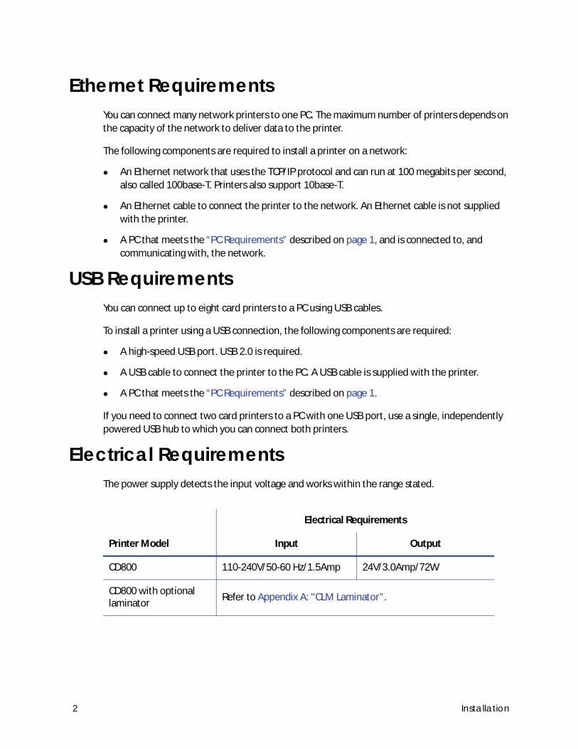
Electrical RequirementsThe power supply detects the input voltage and works within the range stated.
Printer Model
Electrical Requirements
Input Output
CD800 110-240V/50-60 Hz/1.5Amp 24V/3.0Amp/72W
CD800 with optional laminator
Refer to Appendix A: "CLM Laminator”.
2 Installation
Site RequirementsSet up and use the printer in an environment that meets the following requirements.
Place the printer in an environment with temperatures ranging from 60° to 95°F (15° to 35°C).
Use a single-phase, 3-wire, grounded receptacle.
Place the printer and its supplies in a clean office environment, keeping paper and foreign
materials off of the equipment.
Place the printer in a location that provides the following:
A sturdy, level surface. Avoid unstable locations.
A surface that allows easy user access. Refer to “Printer Dimensions” on page 4 for more
information.
Enough space to open all printer doors and to access power cords and data cables. Refer
to “Clearance Requirements” on page 5.
Enough space around the printer to allow for ventilation.
Place the printer away from direct sunlight.
Do not place the printer near heating ducts, fans, or other air vents.
Do not use the printer for purposes other than the intended use.
CD800 Card Printer Installation and Administrator’s Guide 3
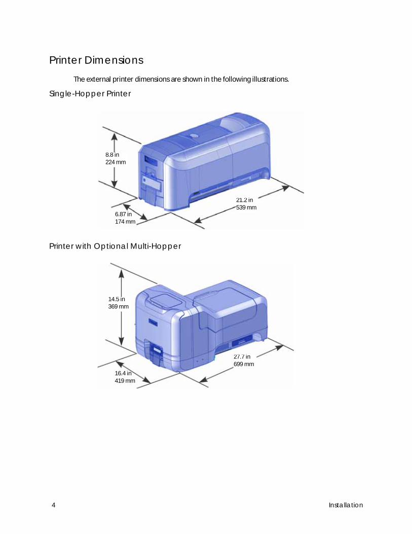
Printer DimensionsThe external printer dimensions are shown in the following illustrations.
Single-Hopper Printer
Printer with Optional Multi-Hopper
8.8 in224 mm
6.87 in174 mm
21.2 in539 mm
14.5 in369 mm
16.4 in419 mm
27.7 in699 mm
4 Installation
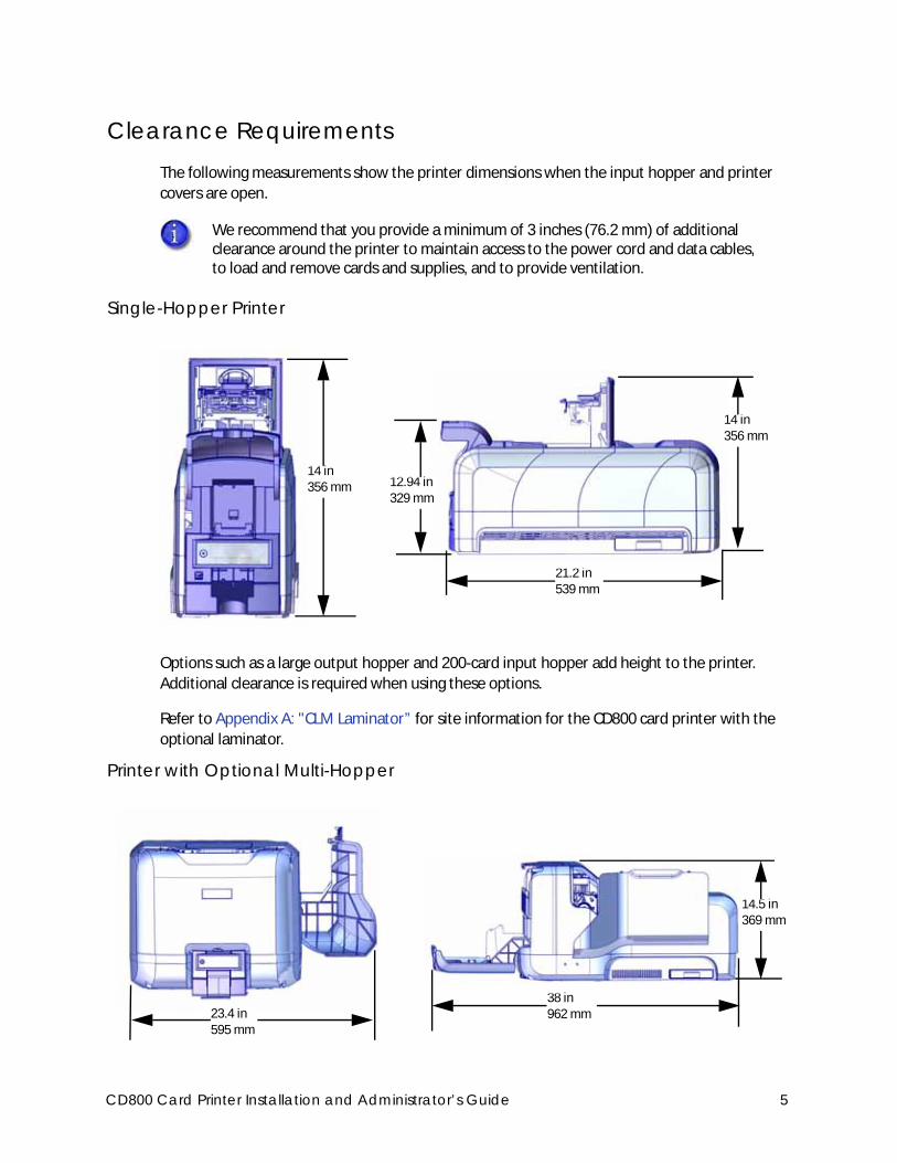
Clearance RequirementsThe following measurements show the printer dimensions when the input hopper and printer
covers are open.
Single-Hopper Printer
Options such as a large output hopper and 200-card input hopper add height to the printer.
Additional clearance is required when using these options.
Refer to Appendix A: "CLM Laminator” for site information for the CD800 card printer with the
optional laminator.
Printer with Optional Multi-Hopper
We recommend that you provide a minimum of 3 inches (76.2 mm) of additional clearance around the printer to maintain access to the power cord and data cables, to load and remove cards and supplies, and to provide ventilation.
14 in356 mm
14 in356 mm
21.2 in539 mm
12.94 in329 mm
23.4 in595 mm
14.5 in369 mm
38 in962 mm
CD800 Card Printer Installation and Administrator’s Guide 5
Secure Printing RequirementsSecure printing consists of encrypting print commands and card data and transmitting the
information securely from the PC to the printer. Printers are shipped with all communication
protocols (secure and non-secure) enabled. Refer to “Behavior” on page 61 for more information
about using the Printer Manager web service to specify printer security settings.
If you use the Card Printer Driver, make sure that the secure printing protocol (DPCL2Secure) is
enabled and that the DPCL2 non-secure communication protocol is disabled. DPCL must remain
enabled for the Card Printer Driver to function. For more information, refer to your printer’s
Driver Guide.
If your card production site requires secure printing, use the following:
Datacard CD800 card printer with secure printing enabled
A PC that meets the PC requirements cited earlier in this section
An Ethernet or USB connection that meet the requirements
A current browser, such as Internet Explorer, Firefox, or Chrome
Set Up the PrinterUse the information in the following sections to set up the printer to print cards.
Prepare the Printer on page 7
Install Optional Equipment on page 12
Connect the Printer to a Computer on page 15
Plug in and Power On the Printer on page 16
Configure the Printer on page 18
Use the Card Printer Driver on page 27 or Use OpenCard Data Format on page 27
6 Installation
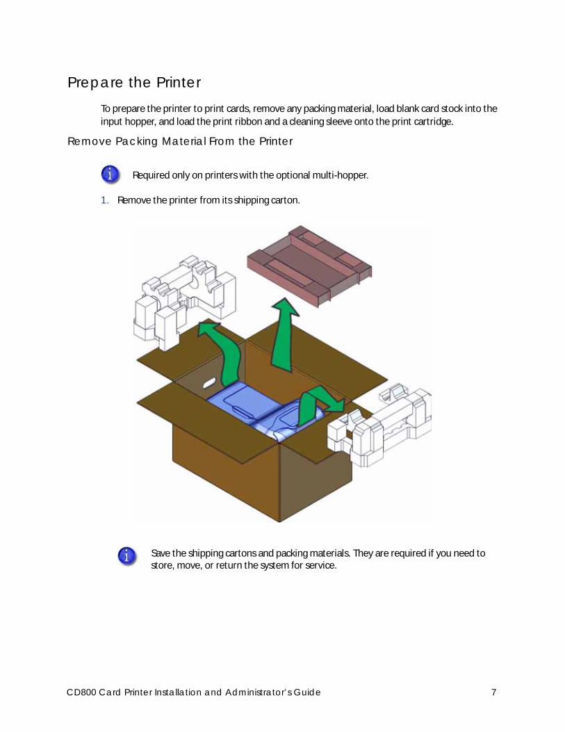
Prepare the PrinterTo prepare the printer to print cards, remove any packing material, load blank card stock into the
input hopper, and load the print ribbon and a cleaning sleeve onto the print cartridge.
Remove Packing Material From the Printer
1. Remove the printer from its shipping carton.
Required only on printers with the optional multi-hopper.
Save the shipping cartons and packing materials. They are required if you need to store, move, or return the system for service.
CD800 Card Printer Installation and Administrator’s Guide 7
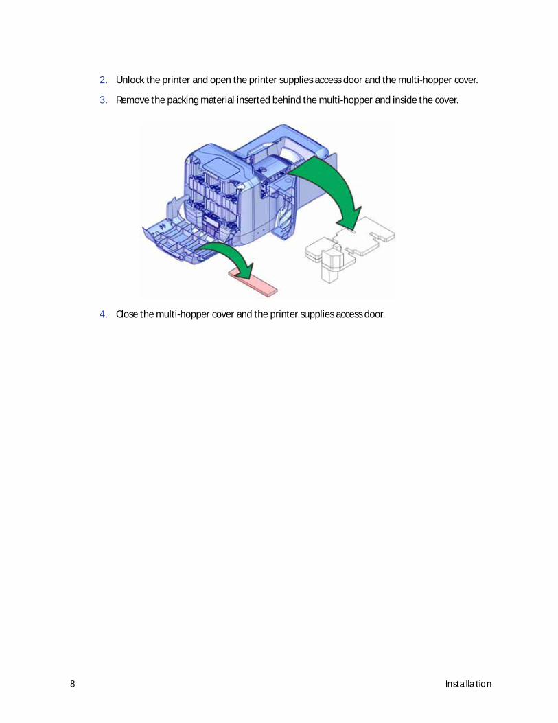
2. Unlock the printer and open the printer supplies access door and the multi-hopper cover.
3. Remove the packing material inserted behind the multi-hopper and inside the cover.
4. Close the multi-hopper cover and the printer supplies access door.
8 Installation
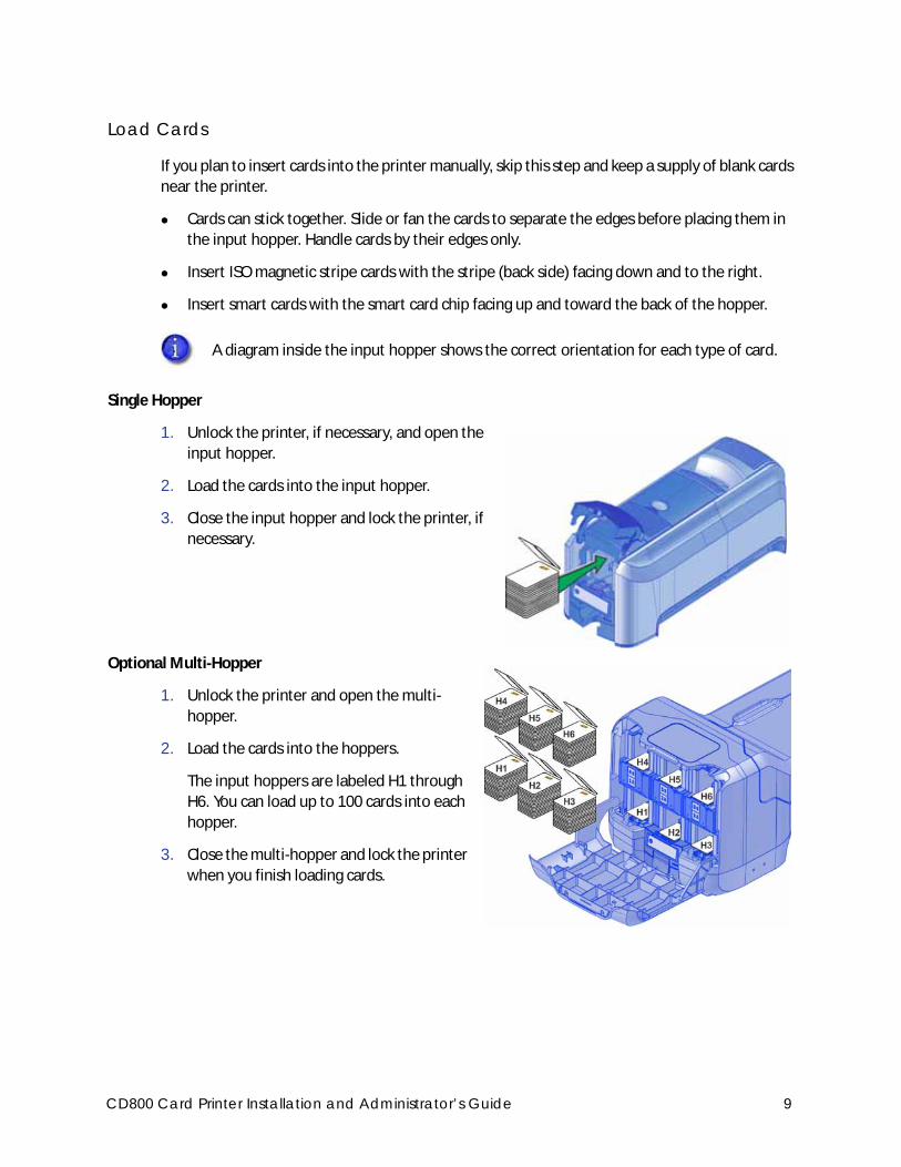
Load Cards
If you plan to insert cards into the printer manually, skip this step and keep a supply of blank cards
near the printer.
Cards can stick together. Slide or fan the cards to separate the edges before placing them in
the input hopper. Handle cards by their edges only.
Insert ISO magnetic stripe cards with the stripe (back side) facing down and to the right.
Insert smart cards with the smart card chip facing up and toward the back of the hopper.
Single Hopper
1. Unlock the printer, if necessary, and open the
input hopper.
2. Load the cards into the input hopper.
3. Close the input hopper and lock the printer, if
necessary.
Optional Multi-Hopper
1. Unlock the printer and open the multi-
hopper.
2. Load the cards into the hoppers.
The input hoppers are labeled H1 through
H6. You can load up to 100 cards into each
hopper.
3. Close the multi-hopper and lock the printer
when you finish loading cards.
A diagram inside the input hopper shows the correct orientation for each type of card.
CD800 Card Printer Installation and Administrator’s Guide 9
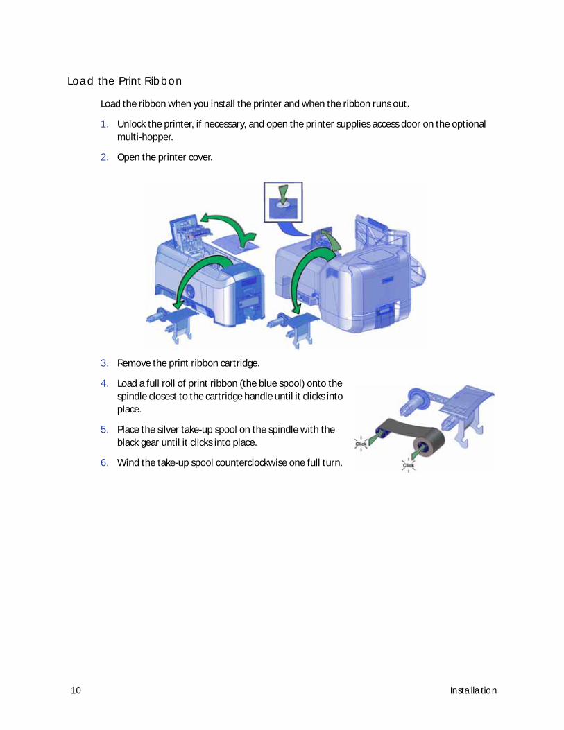
Load the Print Ribbon
Load the ribbon when you install the printer and when the ribbon runs out.
1. Unlock the printer, if necessary, and open the printer supplies access door on the optional
multi-hopper.
2. Open the printer cover.
3. Remove the print ribbon cartridge.
4. Load a full roll of print ribbon (the blue spool) onto the
spindle closest to the cartridge handle until it clicks into
place.
5. Place the silver take-up spool on the spindle with the
black gear until it clicks into place.
6. Wind the take-up spool counterclockwise one full turn.
10 Installation
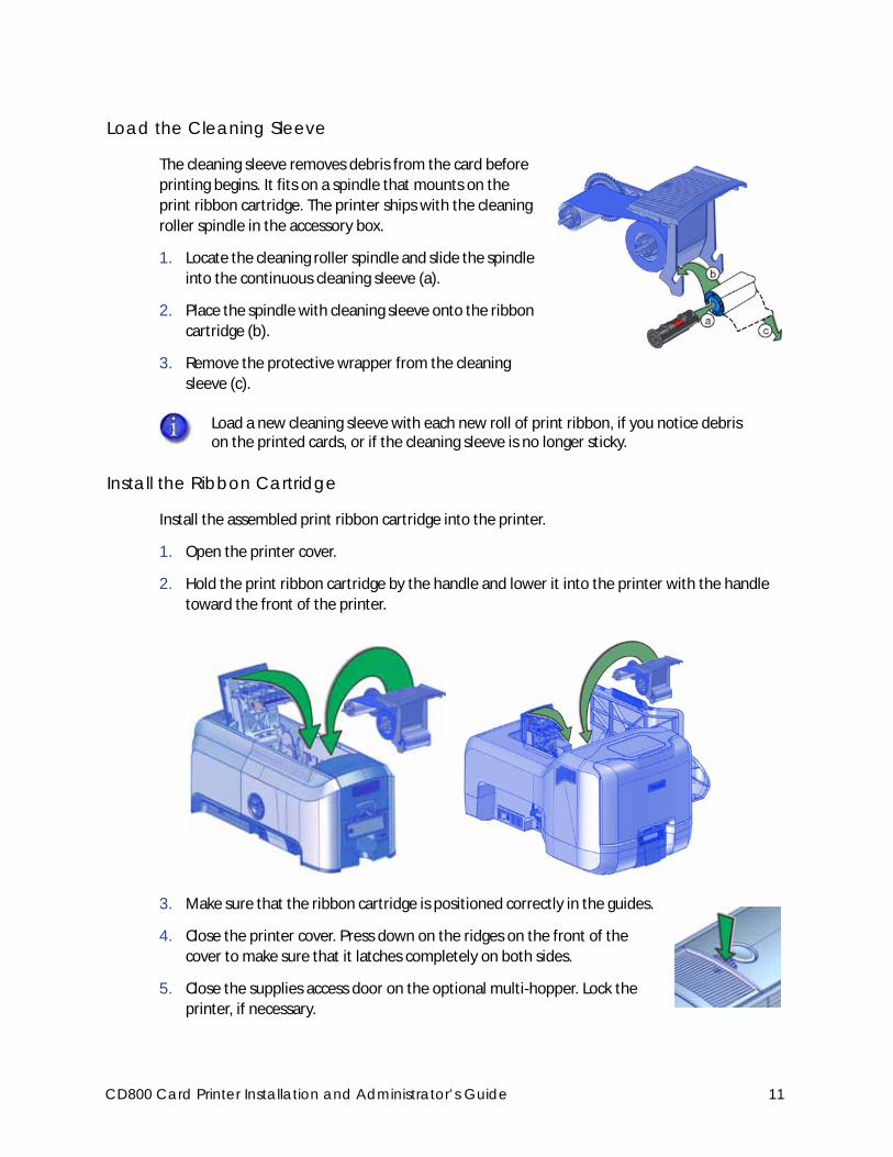
Load the Cleaning Sleeve
The cleaning sleeve removes debris from the card before
printing begins. It fits on a spindle that mounts on the
print ribbon cartridge. The printer ships with the cleaning
roller spindle in the accessory box.
1. Locate the cleaning roller spindle and slide the spindle
into the continuous cleaning sleeve (a).
2. Place the spindle with cleaning sleeve onto the ribbon
cartridge (b).
3. Remove the protective wrapper from the cleaning
sleeve (c).
Install the Ribbon Cartridge
Install the assembled print ribbon cartridge into the printer.
1. Open the printer cover.
2. Hold the print ribbon cartridge by the handle and lower it into the printer with the handle
toward the front of the printer.
3. Make sure that the ribbon cartridge is positioned correctly in the guides.
4. Close the printer cover. Press down on the ridges on the front of the
cover to make sure that it latches completely on both sides.
5. Close the supplies access door on the optional multi-hopper. Lock the
printer, if necessary.
Load a new cleaning sleeve with each new roll of print ribbon, if you notice debris on the printed cards, or if the cleaning sleeve is no longer sticky.
CD800 Card Printer Installation and Administrator’s Guide 11
Install Optional EquipmentYou can install additional equipment on the printer depending on your requirements.
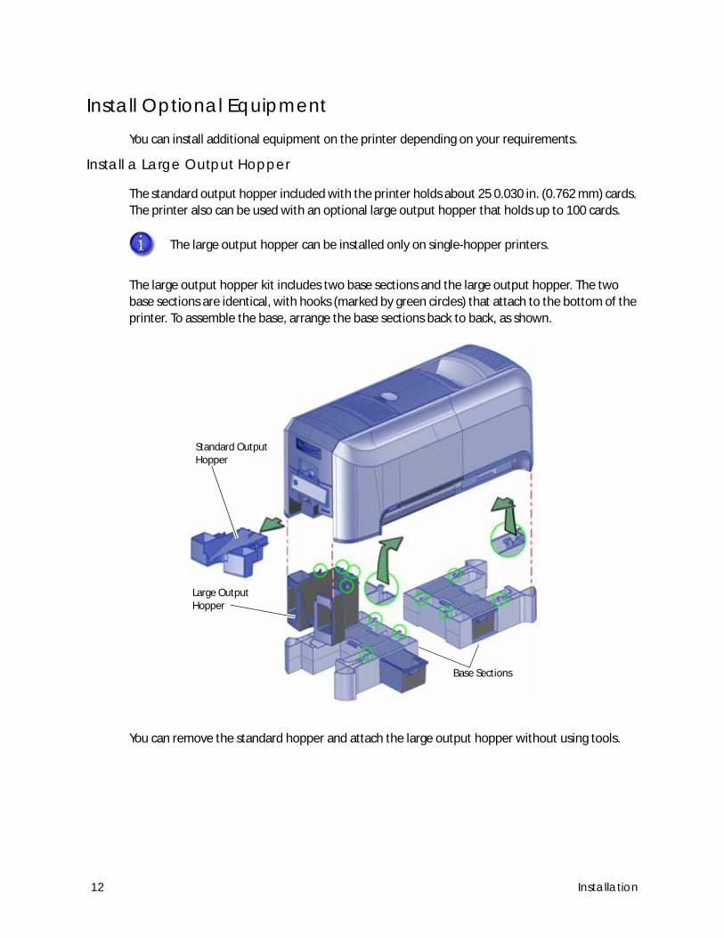
Install a Large Output Hopper
The standard output hopper included with the printer holds about 25 0.030 in. (0.762 mm) cards.
The printer also can be used with an optional large output hopper that holds up to 100 cards.
The large output hopper kit includes two base sections and the large output hopper. The two
base sections are identical, with hooks (marked by green circles) that attach to the bottom of the
printer. To assemble the base, arrange the base sections back to back, as shown.
You can remove the standard hopper and attach the large output hopper without using tools.
The large output hopper can be installed only on single-hopper printers.
Large Output Hopper
Base Sections
Standard Output Hopper
12 Installation

Do the following to attach the printer to the bases, and to install the larger output hopper. You
also can refer to the instructions shipped with the large output hopper kit.
1. Position one base section with the open end facing the back of the printer.
2. Lift the printer over the base section.
3. Align the tabs in the base with the slots in the bottom of the printer.
4. Push up to insert the four tabs in the slots, and then push the base forward to lock it to the
printer.
5. Position the other base section with the opening facing the front of the printer.
6. Push up to insert the four tabs in the slots and then push the base back to lock it to the
printer.
7. Remove the 25-card output hopper from the printer. Slide it out, similar to a drawer.
8. Slide the 100-card output hopper into the assembled base and printer. Make sure that the
tabs (shown in circles in the illustration) secure the hopper to the printer.
HINTS & TIPS
The base sections contain drawers, useful for holding cards, cleaning swabs, or other
frequently used items. The drawers can be opened from either the left or right side of the
printer.
The base and large output hopper remain attached when the printer is moved or carried.
If you install the 100-card output hopper, change the Printer Manager Printer Setting > Transport EjectHopperSpeed setting to ehs_Extended. This allows completed cards to stack properly in the larger output hopper. Refer to “Transport” on page 71 for complete information.
CD800 Card Printer Installation and Administrator’s Guide 13
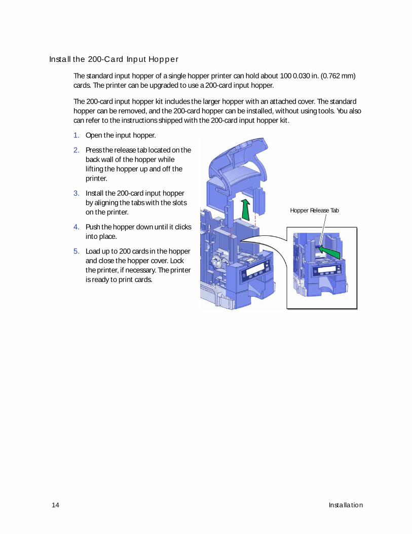
Install the 200-Card Input Hopper
The standard input hopper of a single hopper printer can hold about 100 0.030 in. (0.762 mm)
cards. The printer can be upgraded to use a 200-card input hopper.
The 200-card input hopper kit includes the larger hopper with an attached cover. The standard
hopper can be removed, and the 200-card hopper can be installed, without using tools. You also
can refer to the instructions shipped with the 200-card input hopper kit.
1. Open the input hopper.
2. Press the release tab located on the
back wall of the hopper while
lifting the hopper up and off the
printer.
3. Install the 200-card input hopper
by aligning the tabs with the slots
on the printer.
4. Push the hopper down until it clicks
into place.
5. Load up to 200 cards in the hopper
and close the hopper cover. Lock
the printer, if necessary. The printer
is ready to print cards.
Hopper Release Tab
14 Installation
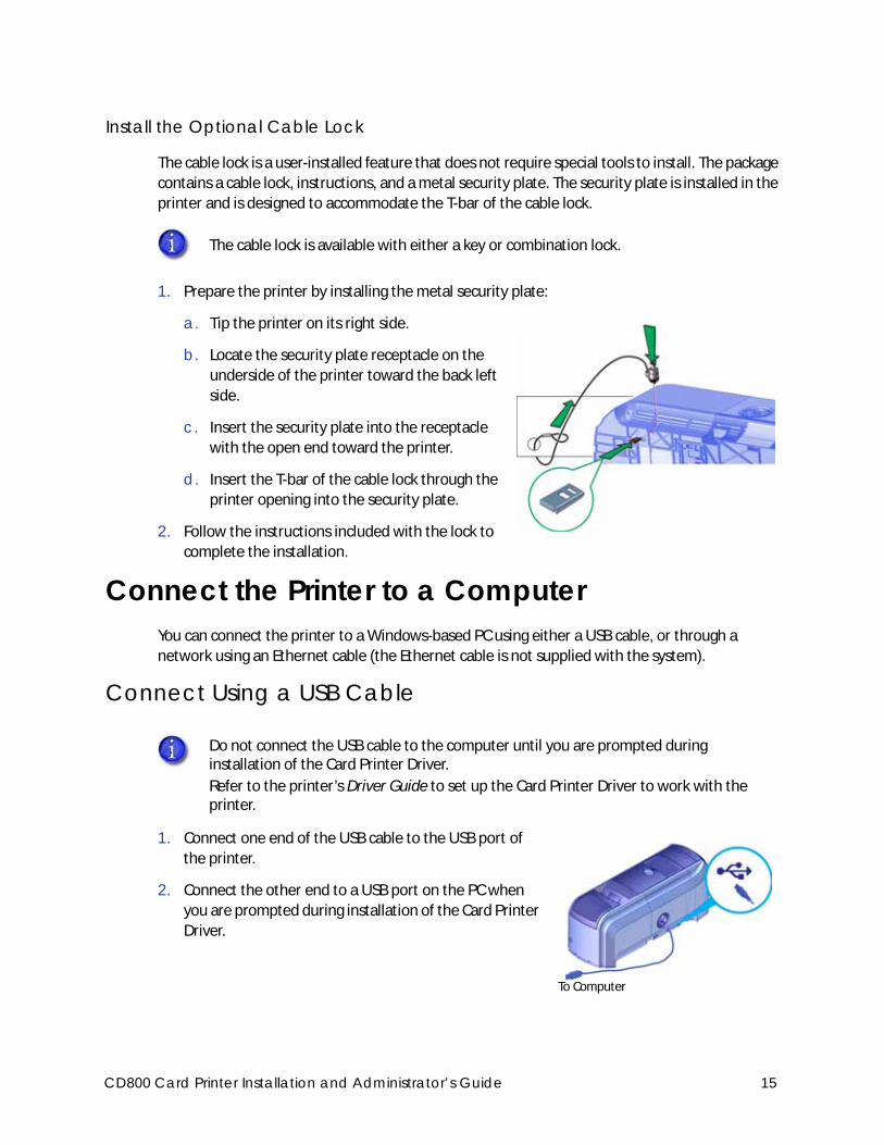
Install the Optional Cable Lock
The cable lock is a user-installed feature that does not require special tools to install. The package
contains a cable lock, instructions, and a metal security plate. The security plate is installed in the
printer and is designed to accommodate the T-bar of the cable lock.
1. Prepare the printer by installing the metal security plate:
a. Tip the printer on its right side.
b. Locate the security plate receptacle on the
underside of the printer toward the back left
side.
c. Insert the security plate into the receptacle
with the open end toward the printer.
d. Insert the T-bar of the cable lock through the
printer opening into the security plate.
2. Follow the instructions included with the lock to
complete the installation.
Connect the Printer to a ComputerYou can connect the printer to a Windows-based PC using either a USB cable, or through a
network using an Ethernet cable (the Ethernet cable is not supplied with the system).
Connect Using a USB Cable
1. Connect one end of the USB cable to the USB port of
the printer.
2. Connect the other end to a USB port on the PC when
you are prompted during installation of the Card Printer
Driver.
The cable lock is available with either a key or combination lock.
Do not connect the USB cable to the computer until you are prompted during installation of the Card Printer Driver.
Refer to the printer’s Driver Guide to set up the Card Printer Driver to work with the printer.
To Computer
CD800 Card Printer Installation and Administrator’s Guide 15
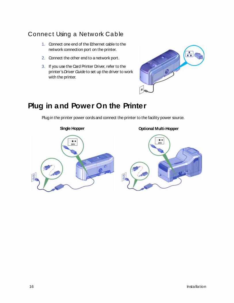
Connect Using a Network Cable1. Connect one end of the Ethernet cable to the
network connection port on the printer.
2. Connect the other end to a network port.
3. If you use the Card Printer Driver, refer to the
printer’s Driver Guide to set up the driver to work
with the printer.
Plug in and Power On the PrinterPlug in the printer power cords and connect the printer to the facility power source.
Single Hopper Optional Multi-Hopper
16 Installation
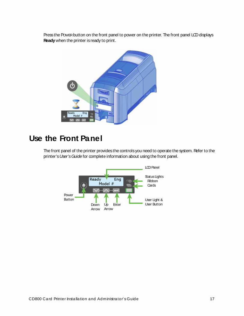
Press the POWER button on the front panel to power on the printer. The front panel LCD displays
Ready when the printer is ready to print.
Use the Front PanelThe front panel of the printer provides the controls you need to operate the system. Refer to the
printer’s User’s Guide for complete information about using the front panel.
Status LightsRibbonCards
User Light & User ButtonUp
ArrowEnterDown
Arrow
Power Button
LCD Panel
CD800 Card Printer Installation and Administrator’s Guide 17
Configure the PrinterThe printer supports both IPv4 and IPv6 addressing. If your network environment uses IPv6, you
may be required to use the LCD Configuration menu to enable the IPv6 settings that manage the
printer communication over an Ethernet network. You do not need to make any configuration
changes to use IPv4.
Use IPv4 AddressingWhen you use IPv4, the printer can use either of the following network communication methods:
DHCP (Dynamic Host Configuration Protocol)—The network automatically assigns the IP
address to the printer. The IP address of a printer that uses DHCP can change if the printer is
powered off and back on.
Static IP—You set the IP address, subnet mask, and gateway address, as provided by your
network support personnel. A static IP address does not change when the printer is powered
off. Some sites may require that the printer has the same IP address at all times. Refer to “Set
a Static IPv4 Address (Optional)”.
Set a Static IPv4 Address (Optional)
The default communications method is DHCP (Dynamic Host Configuration Protocol). If you need
to assign a static IP address, you can use the front panel to change the address method and enter
the address information.
1. Obtain the following values from your network support personnel. Make sure you receive all
three values:
IP address
Subnet mask
Gateway address
You also can use Printer Manager to change the communication method and define printer address information. Refer to “Communication” on page 56.
You can set a static IP address on a printer even if it is not connected to the network. For example, a group may set up several printers in a central location before installing them at individual sites. You can test the IP address by setting up a local network. Refer to “Test the IP Address Using a Local Network” on page 25 for more information.
18 Installation
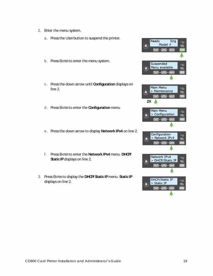
2. Enter the menu system.
a. Press the USER button to suspend the printer.
b. Press ENTER to enter the menu system.
c. Press the down arrow until Configuration displays on
line 2.
d. Press ENTER to enter the Configuration menu.
e. Press the down arrow to display Network IPv4 on line 2.
f. Press ENTER to enter the Network IPv4 menu. DHCP/
Static IP displays on line 2.
3. Press ENTER to display the DHCP/Static IP menu. Static IP
displays on line 2.
2X
CD800 Card Printer Installation and Administrator’s Guide 19
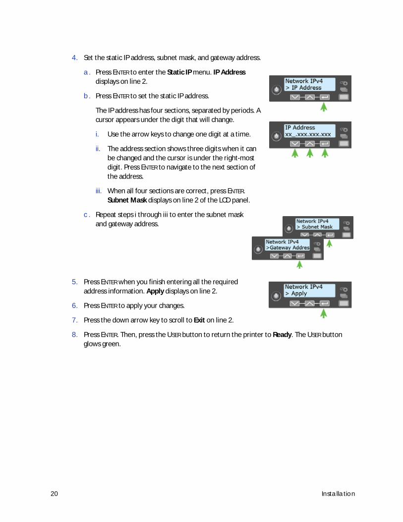
4. Set the static IP address, subnet mask, and gateway address.
a. Press ENTER to enter the Static IP menu. IP Address
displays on line 2.
b. Press ENTER to set the static IP address.
The IP address has four sections, separated by periods. A
cursor appears under the digit that will change.
i. Use the arrow keys to change one digit at a time.
ii. The address section shows three digits when it can
be changed and the cursor is under the right-most
digit. Press ENTER to navigate to the next section of
the address.
iii. When all four sections are correct, press ENTER.
Subnet Mask displays on line 2 of the LCD panel.
c. Repeat steps i through iii to enter the subnet mask
and gateway address.
5. Press ENTER when you finish entering all the required
address information. Apply displays on line 2.
6. Press ENTER to apply your changes.
7. Press the down arrow key to scroll to Exit on line 2.
8. Press ENTER. Then, press the USER button to return the printer to Ready. The USER button
glows green.
20 Installation
Use IPv6 AddressingThe expanded address space provided by IPv6 is becoming increasingly common in network
environments. A printer on an IPv6 network can be configured to use one or more of the
following methods, depending on how the network is set up:
Link Local IPv6 address: The printer and PC clients are restricted to the same subnet. Link
local is enabled automatically when IPv6 is enabled and offers the best security for your
network.
DHCPv6: A DHCPv6 server is externally configured to give out an IPv6 address.
Stateless Address AutoConfiguration (SLAAC): One or more routers with IPv6 enabled on the
subnet give out a subnet prefix that allows access to IP addresses.
Manual IPv6 Address: The printer has a designated IPv6 address on a specified subnet. The
address does not change without manual intervention. This is similar to an IPv4 static IP
address.
To use IPv6 with the card printer, you need to connect to an IPv6 network and enable one or
more address configuration methods. Link local, DHCPv6, and SLAAC automatically configure an
address, but may require the necessary network support (DHCPv6 and routers). Refer to “Enable
IPv6” on page 21 for complete information about how to enable IPv6.
Enable IPv6
Use the front panel Configuration menu to enable the IPv6 method used by your network.
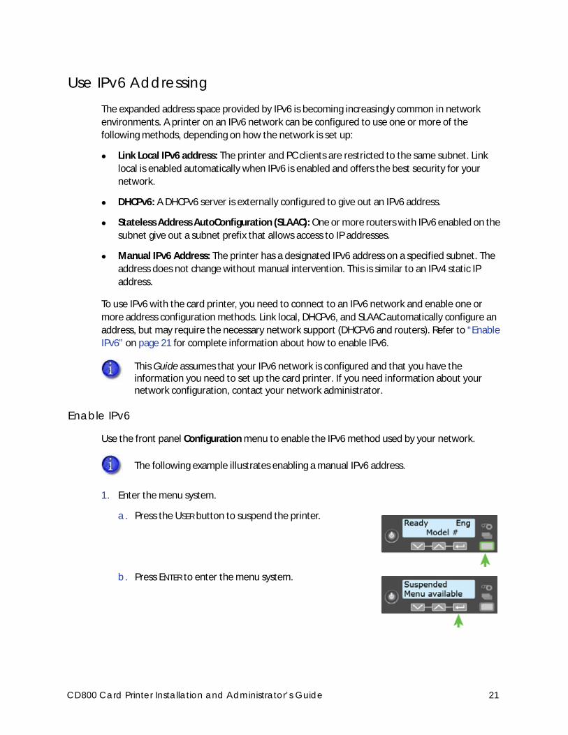
1. Enter the menu system.
a. Press the USER button to suspend the printer.
b. Press ENTER to enter the menu system.
This Guide assumes that your IPv6 network is configured and that you have the information you need to set up the card printer. If you need information about your network configuration, contact your network administrator.
The following example illustrates enabling a manual IPv6 address.
CD800 Card Printer Installation and Administrator’s Guide 21
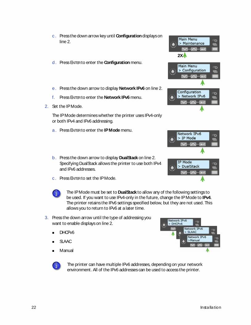
c. Press the down arrow key until Configuration displays on
line 2.
d. Press ENTER to enter the Configuration menu.
e. Press the down arrow to display Network IPv6 on line 2.
f. Press ENTER to enter the Network IPv6 menu.
2. Set the IP Mode.
The IP Mode determines whether the printer uses IPv4-only
or both IPv4 and IPv6 addressing.
a. Press ENTER to enter the IP Mode menu.
b. Press the down arrow to display DualStack on line 2.
Specifying DualStack allows the printer to use both IPv4
and IPv6 addresses.
c. Press ENTER to set the IP Mode.
3. Press the down arrow until the type of addressing you
want to enable displays on line 2.
DHCPv6
SLAAC
Manual
The IP Mode must be set to DualStack to allow any of the following settings to be used. If you want to use IPv4-only in the future, change the IP Mode to IPv4. The printer retains the IPv6 settings specified below, but they are not used. This allows you to return to IPv6 at a later time.
The printer can have multiple IPv6 addresses, depending on your network environment. All of the IPv6 addresses can be used to access the printer.
2X
22 Installation
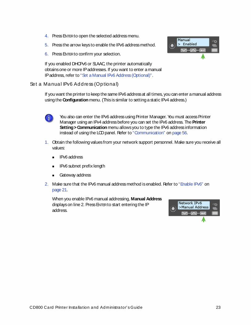
4. Press ENTER to open the selected address menu.
5. Press the arrow keys to enable the IPv6 address method.
6. Press ENTER to confirm your selection.
If you enabled DHCPv6 or SLAAC, the printer automatically
obtains one or more IP addresses. If you want to enter a manual
IP address, refer to “Set a Manual IPv6 Address (Optional)”.
Set a Manual IPv6 Address (Optional)
If you want the printer to keep the same IPv6 address at all times, you can enter a manual address
using the Configuration menu. (This is similar to setting a static IPv4 address.)
1. Obtain the following values from your network support personnel. Make sure you receive all
values:
IPv6 address
IPv6 subnet prefix length
Gateway address
2. Make sure that the IPv6 manual address method is enabled. Refer to “Enable IPv6” on
page 21.
When you enable IPv6 manual addressing, Manual Address
displays on line 2. Press ENTER to start entering the IP
address.
You also can enter the IPv6 address using Printer Manager. You must access Printer Manager using an IPv4 address before you can set the IPv6 address. The Printer Setting > Communication menu allows you to type the IPv6 address information instead of using the LCD panel. Refer to “Communication” on page 56.
CD800 Card Printer Installation and Administrator’s Guide 23
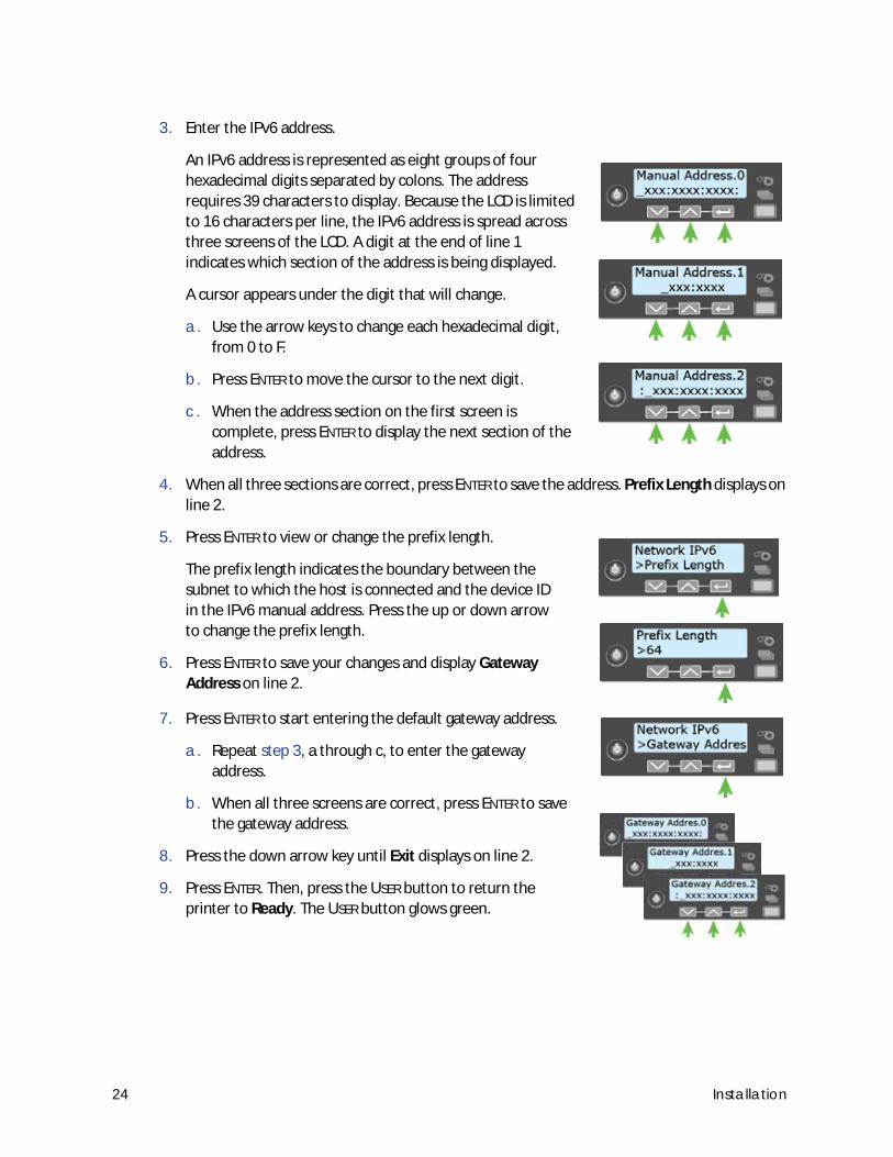
3. Enter the IPv6 address.
An IPv6 address is represented as eight groups of four
hexadecimal digits separated by colons. The address
requires 39 characters to display. Because the LCD is limited
to 16 characters per line, the IPv6 address is spread across
three screens of the LCD. A digit at the end of line 1
indicates which section of the address is being displayed.
A cursor appears under the digit that will change.
a. Use the arrow keys to change each hexadecimal digit,
from 0 to F.
b. Press ENTER to move the cursor to the next digit.
c. When the address section on the first screen is
complete, press ENTER to display the next section of the
address.
4. When all three sections are correct, press ENTER to save the address. Prefix Length displays on
line 2.
5. Press ENTER to view or change the prefix length.
The prefix length indicates the boundary between the
subnet to which the host is connected and the device ID
in the IPv6 manual address. Press the up or down arrow
to change the prefix length.
6. Press ENTER to save your changes and display Gateway
Address on line 2.
7. Press ENTER to start entering the default gateway address.
a. Repeat step 3, a through c, to enter the gateway
address.
b. When all three screens are correct, press ENTER to save
the gateway address.
8. Press the down arrow key until Exit displays on line 2.
9. Press ENTER. Then, press the USER button to return the
printer to Ready. The USER button glows green.
24 Installation
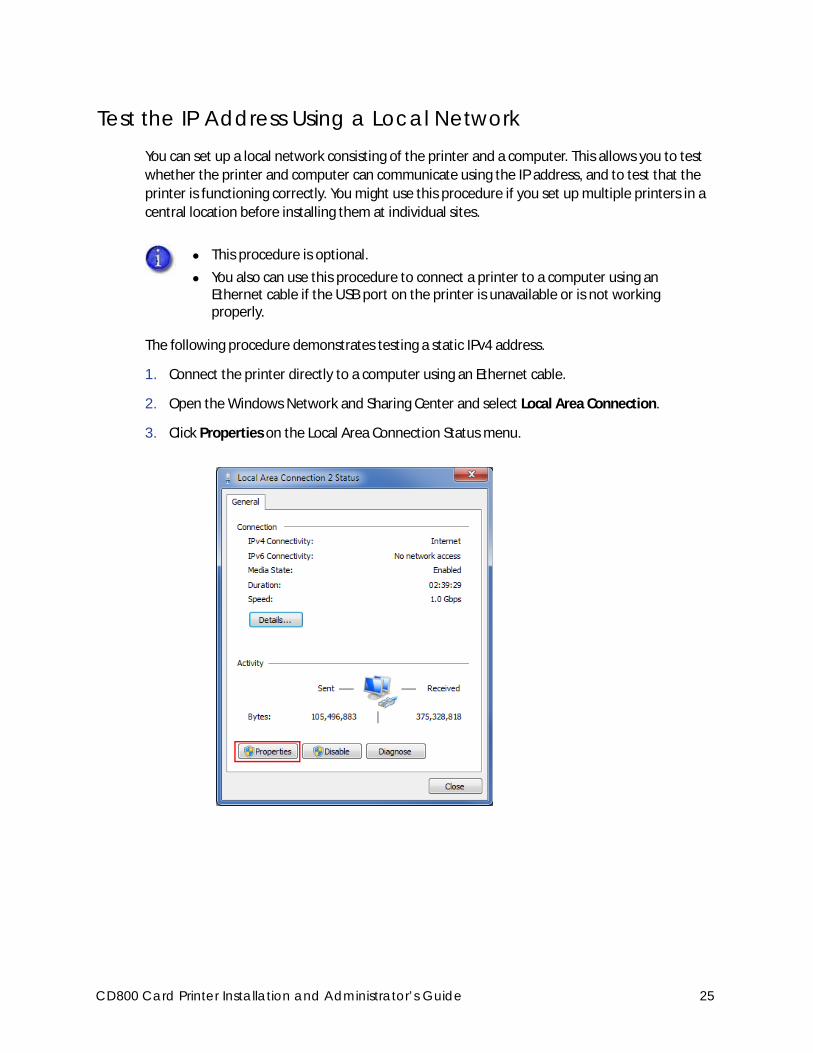
Test the IP Address Using a Local NetworkYou can set up a local network consisting of the printer and a computer. This allows you to test
whether the printer and computer can communicate using the IP address, and to test that the
printer is functioning correctly. You might use this procedure if you set up multiple printers in a
central location before installing them at individual sites.
The following procedure demonstrates testing a static IPv4 address.
1. Connect the printer directly to a computer using an Ethernet cable.
2. Open the Windows Network and Sharing Center and select Local Area Connection.
3. Click Properties on the Local Area Connection Status menu.
This procedure is optional.
You also can use this procedure to connect a printer to a computer using an Ethernet cable if the USB port on the printer is unavailable or is not working properly.
CD800 Card Printer Installation and Administrator’s Guide 25
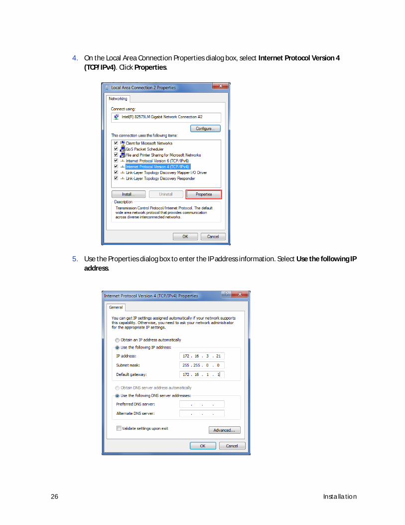
4. On the Local Area Connection Properties dialog box, select Internet Protocol Version 4
(TCP/IPv4). Click Properties.
5. Use the Properties dialog box to enter the IP address information. Select Use the following IP
address.
26 Installation
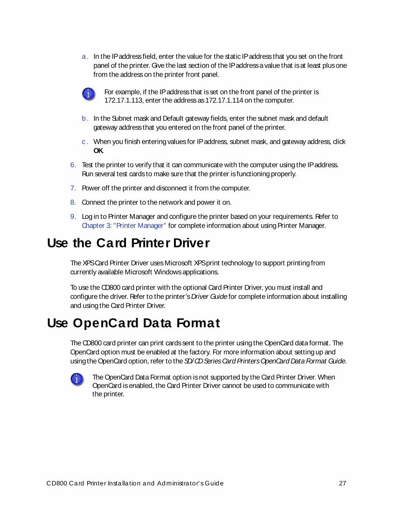
a. In the IP address field, enter the value for the static IP address that you set on the front
panel of the printer. Give the last section of the IP address a value that is at least plus one
from the address on the printer front panel.
b. In the Subnet mask and Default gateway fields, enter the subnet mask and default
gateway address that you entered on the front panel of the printer.
c. When you finish entering values for IP address, subnet mask, and gateway address, click
OK.
6. Test the printer to verify that it can communicate with the computer using the IP address.
Run several test cards to make sure that the printer is functioning properly.
7. Power off the printer and disconnect it from the computer.
8. Connect the printer to the network and power it on.
9. Log in to Printer Manager and configure the printer based on your requirements. Refer to
Chapter 3: "Printer Manager” for complete information about using Printer Manager.
Use the Card Printer DriverThe XPS Card Printer Driver uses Microsoft XPS print technology to support printing from
currently available Microsoft Windows applications.
To use the CD800 card printer with the optional Card Printer Driver, you must install and
configure the driver. Refer to the printer’s Driver Guide for complete information about installing
and using the Card Printer Driver.
Use OpenCard Data FormatThe CD800 card printer can print cards sent to the printer using the OpenCard data format. The
OpenCard option must be enabled at the factory. For more information about setting up and
using the OpenCard option, refer to the SD/CD Series Card Printers OpenCard Data Format Guide.
For example, if the IP address that is set on the front panel of the printer is 172.17.1.113, enter the address as 172.17.1.114 on the computer.
The OpenCard Data Format option is not supported by the Card Printer Driver. When OpenCard is enabled, the Card Printer Driver cannot be used to communicate with the printer.
CD800 Card Printer Installation and Administrator’s Guide 27

28 Installation
Chapter 2: Elements of Card Design
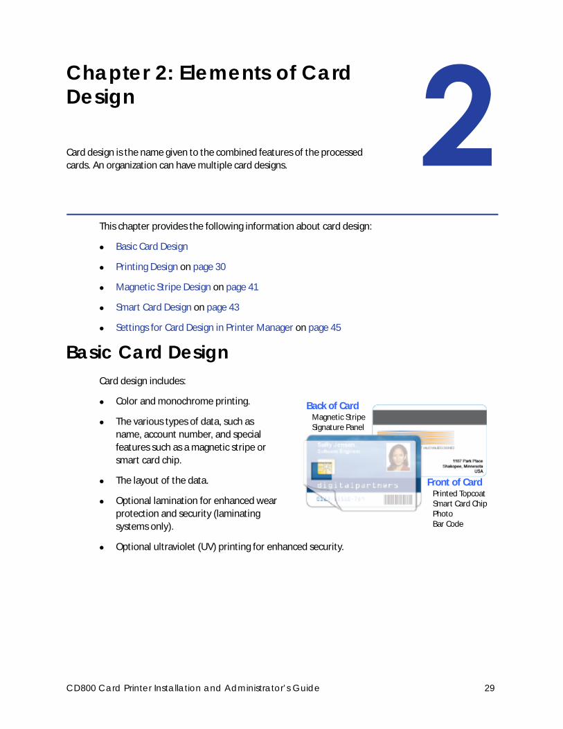
Card design is the name given to the combined features of the processed
cards. An organization can have multiple card designs.
This chapter provides the following information about card design:
Basic Card Design
Printing Design on page 30
Magnetic Stripe Design on page 41
Smart Card Design on page 43
Settings for Card Design in Printer Manager on page 45
Basic Card DesignCard design includes:
Color and monochrome printing.
The various types of data, such as
name, account number, and special
features such as a magnetic stripe or
smart card chip.
The layout of the data.
Optional lamination for enhanced wear
protection and security (laminating
systems only).
Optional ultraviolet (UV) printing for enhanced security.
Back of CardMagnetic StripeSignature Panel
Front of CardPrinted TopcoatSmart Card ChipPhotoBar Code
CD800 Card Printer Installation and Administrator’s Guide 29
Printing DesignPrinting design includes color and monochrome printing, bar code printing, non-printing areas,
and card layout.
Color PrintingColor print ribbon is available in full-panel and short-panel styles.
Full-Panel Ribbon
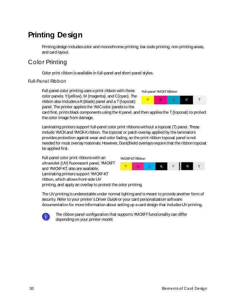
Full-panel color printing uses a print ribbon with three
color panels: Y (yellow), M (magenta), and C (cyan). The
ribbon also includes a K (black) panel and a T (topcoat)
panel. The printer applies the YMC color panels to the
card first, prints black components using the K panel, and then applies the T (topcoat) to protect
the color image from damage.
Laminating printers support full-panel color print ribbons without a topcoat (T) panel. These
include YMCK and YMCK-K ribbon. The topcoat or patch overlay applied by the laminators
provides protection against wear and color fading, so the print ribbon topcoat panel is not
needed for most overlay materials. However, DuraShield overlays require that the ribbon topcoat
be applied first.
Full-panel color print ribbons with an
ultraviolet (UV) fluorescent panel, YMCKFT
and YMCKF-KT, also are available.
Laminating printers support YMCKF-KT
ribbon, which allows front-side UV
printing, and apply an overlay to protect the color printing.
The UV printing is undetectable under normal lighting and is meant to provide another form of
security. Refer to your printer’s Driver Guide or your card personalization software
documentation for more information about setting up a card design that includes UV printing.
The ribbon panel configuration that supports YMCKFT functionality can differ depending on your printer model.
Full-panel YMCKT Ribbon
YMCKF-KT Ribbon
30 Elements of Card Design
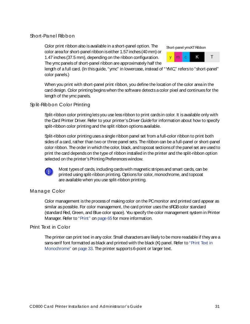
Short-Panel Ribbon
Color print ribbon also is available in a short-panel option. The
color area for short-panel ribbon is either 1.57 inches (40 mm) or
1.47 inches (37.5 mm), depending on the ribbon configuration.
The ymc panels of short-panel ribbon are approximately half the
length of a full card. (In this guide, “ymc” in lowercase, instead of “YMC,” refers to “short-panel”
color panels.)
When you print with short-panel print ribbon, you define the location of the color area in the
card design. Color printing begins when the software detects a color pixel and continues for the
length of the ymc panels.
Split-Ribbon Color Printing
Split-ribbon color printing lets you use less ribbon to print cards in color. It is available only with
the Card Printer Driver. Refer to your printer’s Driver Guide for information about how to specify
split-ribbon color printing and the split ribbon options available.
Split-ribbon color printing uses a single ribbon panel set from a full-color ribbon to print both
sides of a card, rather than two or three panel sets. The ribbon can be a full-panel or short-panel
color ribbon. The order in which the color, black, and topcoat sections of the panel set are used to
print the card depends on the type of ribbon installed in the printer and the split-ribbon option
selected on the printer’s Printing Preferences window.
Manage Color
Color management is the process of making color on the PC monitor and printed card appear as
similar as possible. For color management, the card printer uses the sRGB color standard
(standard Red, Green, and Blue color space). You specify the color management system in Printer
Manager. Refer to “Print” on page 65 for more information.
Print Text in Color
The printer can print text in any color. Small characters are likely to be more readable if they are a
sans-serif font formatted as black and printed with the black (K) panel. Refer to “Print Text in
Monochrome” on page 33. The printer supports 6-point or larger text.
Most types of cards, including cards with magnetic stripes and smart cards, can be printed using split-ribbon printing. Options for color, monochrome, and topcoat are available when you use split-ribbon printing.
Short-panel ymcKT Ribbon
CD800 Card Printer Installation and Administrator’s Guide 31
Print Graphics in Color
The printer produces full-color images from most types of graphics. It can use BMP, JPEG, TIFF,
and PNG file formats for photos and logos.
Vector graphics, such as WMF and SVG files, have components such as shapes with lines and fills.
Components defined as black normally print with the K panel.
Because the printer uses the print ribbon panels in sequence (YMC first, then K), black images can
print over color graphics. For the best appearance of color graphics, or to prevent backgrounds
that are black from printing over colored images, use a color that appears black but is not, so that
all parts of an image print with the YMC panels. For example, in the RGB color space, 0, 0, 0 is
black (and prints with the K panel), but 0, 0, 5 is not black (and prints with the YMC panels).
Types of Color Images
Cards can include both color photos and color logos. The logo is usually the same on each card,
and the photo is unique. Follow these guidelines to obtain the best results for printing both logos
and photos.
1. Evaluate the color quality of the photos:
a. Adjust the image capture system to get the best quality photos; work with distance,
lighting, and camera settings to obtain consistent, high-quality photos.
b. Evaluate the quality of printed photos after the image capture system is optimized.
2. Evaluate the other color areas of the card, such as text or logo:
a. Check your card production application for settings that can help improve the printed
color of text.
b. Use an image editing application to adjust the color of a logo file for optimal printing.
Monochrome PrintingMonochrome printing prints cards using a single color. You can use a full-color ribbon or a
monochrome ribbon that has only one color.
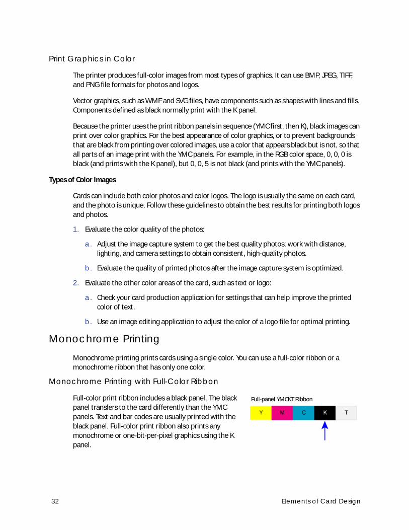
Monochrome Printing with Full-Color Ribbon
Full-color print ribbon includes a black panel. The black
panel transfers to the card differently than the YMC
panels. Text and bar codes are usually printed with the
black panel. Full-color print ribbon also prints any
monochrome or one-bit-per-pixel graphics using the K
panel.
Full-panel YMCKT Ribbon
32 Elements of Card Design
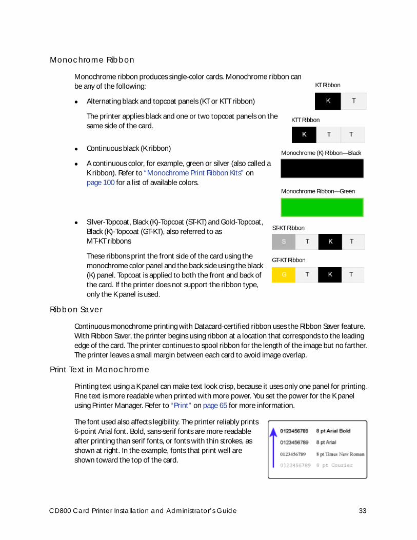
Monochrome Ribbon
Monochrome ribbon produces single-color cards. Monochrome ribbon can
be any of the following:
Alternating black and topcoat panels (KT or KTT ribbon)
The printer applies black and one or two topcoat panels on the
same side of the card.
Continuous black (K ribbon)
A continuous color, for example, green or silver (also called a
K ribbon). Refer to “Monochrome Print Ribbon Kits” on
page 100 for a list of available colors.
Silver-Topcoat, Black (K)-Topcoat (ST-KT) and Gold-Topcoat,
Black (K)-Topcoat (GT-KT), also referred to as
MT-KT ribbons
These ribbons print the front side of the card using the
monochrome color panel and the back side using the black
(K) panel. Topcoat is applied to both the front and back of
the card. If the printer does not support the ribbon type,
only the K panel is used.
Ribbon Saver
Continuous monochrome printing with Datacard-certified ribbon uses the Ribbon Saver feature.
With Ribbon Saver, the printer begins using ribbon at a location that corresponds to the leading
edge of the card. The printer continues to spool ribbon for the length of the image but no farther.
The printer leaves a small margin between each card to avoid image overlap.
Print Text in Monochrome
Printing text using a K panel can make text look crisp, because it uses only one panel for printing.
Fine text is more readable when printed with more power. You set the power for the K panel
using Printer Manager. Refer to “Print” on page 65 for more information.
The font used also affects legibility. The printer reliably prints
6-point Arial font. Bold, sans-serif fonts are more readable
after printing than serif fonts, or fonts with thin strokes, as
shown at right. In the example, fonts that print well are
shown toward the top of the card.
KT Ribbon
KTT Ribbon
Monochrome (K) Ribbon—Black
Monochrome Ribbon—Green
ST-KT Ribbon
GT-KT Ribbon
CD800 Card Printer Installation and Administrator’s Guide 33
Print Bar CodesBar code design follows a set of standards based on the type of bar code produced. Bar codes
contain a series of black lines (bars) separated by white areas (spaces). Each character of encoded
data is represented by a set of bars and spaces. A bar code standard specifies the number and
width of bars and spaces needed to encode a character. The standard also specifies the minimum
size of the white area, or quiet zone, that surrounds the bar code.
Bar Code Guidelines
Bar codes print more successfully when you observe the following guidelines. Follow the
standards for the type of bar code you are printing.
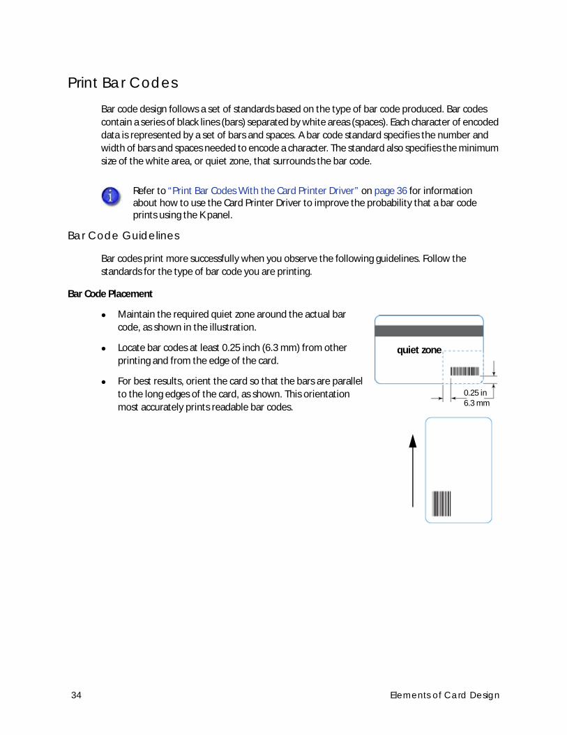
Bar Code Placement
Maintain the required quiet zone around the actual bar
code, as shown in the illustration.
Locate bar codes at least 0.25 inch (6.3 mm) from other
printing and from the edge of the card.
For best results, orient the card so that the bars are parallel
to the long edges of the card, as shown. This orientation
most accurately prints readable bar codes.
Refer to “Print Bar Codes With the Card Printer Driver” on page 36 for information about how to use the Card Printer Driver to improve the probability that a bar code prints using the K panel.
0.25 in6.3 mm
quiet zone
34 Elements of Card Design

Bar Code Size
A lower density bar code is easier to read, because the bars are wider and spaced farther
apart.
The width of the narrow elements in the bar code must be large enough to be read
consistently. The capabilities of the bar code reader can influence this.
The bar code must be tall enough to be read under normal conditions.
Bar Code Print Settings
To achieve the best quality printing and improve the readability of the bar code, use the K
(black) panel of color print ribbon to print the black bars. Bar codes printed with YMC panels
are not as crisp and sharp as those printed with the K panel only. Refer to the printer’s Driver
Guide or the documentation for your card personalization software for more information
about how to print bar codes using the K panel.
Infrared readers require that the K panel be used to print the bar code.
Test Bar Codes
Always test the readability of bar codes under production conditions. Factors to consider include:
If you print cards one at a time, print the samples using that method. If you print cards in
batch (many cards sent to the printer at the same time), use a production-sized batch and
evaluate cards from the beginning, middle, and end of the batch.
Use exactly the same card stock for testing that you use for production. The card stock can
affect the readability of bar codes. Usually, a white surface that reflects light in many
directions is needed. Test cards before purchasing production quantities.
Include other card design components that you use in production, such as topcoat.
Use the same bar code readers as users have, and test each card multiple times to simulate
any wear the card might experience. Also test multiple cards.
CD800 Card Printer Installation and Administrator’s Guide 35

Card Design Changes That Affect Bar Codes
If you make substantial changes to the way you produce cards, review your setup tasks to make
sure that cards continue to have the quality you require.
Changes that can affect bar codes include:
Purchasing a new brand of card stock, which can change the color of some images.
Changing to, or from, preprinted cards, which can change the color of some images.
If you change the design of your cards, or if you start producing an additional card design, test
each design as described in “Test Bar Codes” on page 35 to make sure that the bar code prints as
expected.
Print Bar Codes With the Card Printer Driver
The Card Printer Driver includes a setting that allows the printer to use the black (K) panel to
print the bars of a bar code embedded in a color image, making it more likely to be read by a
scanner. Refer to the printer’s Driver Guide for complete information about how to specify the
“Print black image pixels using monochrome” option.
36 Elements of Card Design
Apply TopcoatFull-color and UV printing fades if it lacks topcoat protection. Topcoat protects the printed image
on the card. It is applied as an even, consistent film.
Make sure that all color printing is covered with topcoat (except for areas such as a magnetic
stripe, smart card chip, or signature panel).
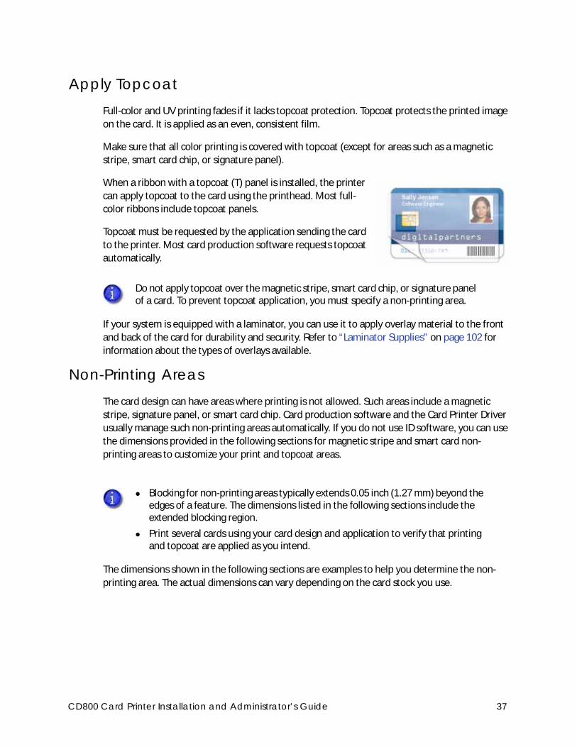
When a ribbon with a topcoat (T) panel is installed, the printer
can apply topcoat to the card using the printhead. Most full-
color ribbons include topcoat panels.
Topcoat must be requested by the application sending the card
to the printer. Most card production software requests topcoat
automatically.
If your system is equipped with a laminator, you can use it to apply overlay material to the front
and back of the card for durability and security. Refer to “Laminator Supplies” on page 102 for
information about the types of overlays available.
Non-Printing AreasThe card design can have areas where printing is not allowed. Such areas include a magnetic
stripe, signature panel, or smart card chip. Card production software and the Card Printer Driver
usually manage such non-printing areas automatically. If you do not use ID software, you can use
the dimensions provided in the following sections for magnetic stripe and smart card non-
printing areas to customize your print and topcoat areas.
The dimensions shown in the following sections are examples to help you determine the non-
printing area. The actual dimensions can vary depending on the card stock you use.
Do not apply topcoat over the magnetic stripe, smart card chip, or signature panel of a card. To prevent topcoat application, you must specify a non-printing area.
Blocking for non-printing areas typically extends 0.05 inch (1.27 mm) beyond the edges of a feature. The dimensions listed in the following sections include the extended blocking region.
Print several cards using your card design and application to verify that printing and topcoat are applied as you intend.
CD800 Card Printer Installation and Administrator’s Guide 37
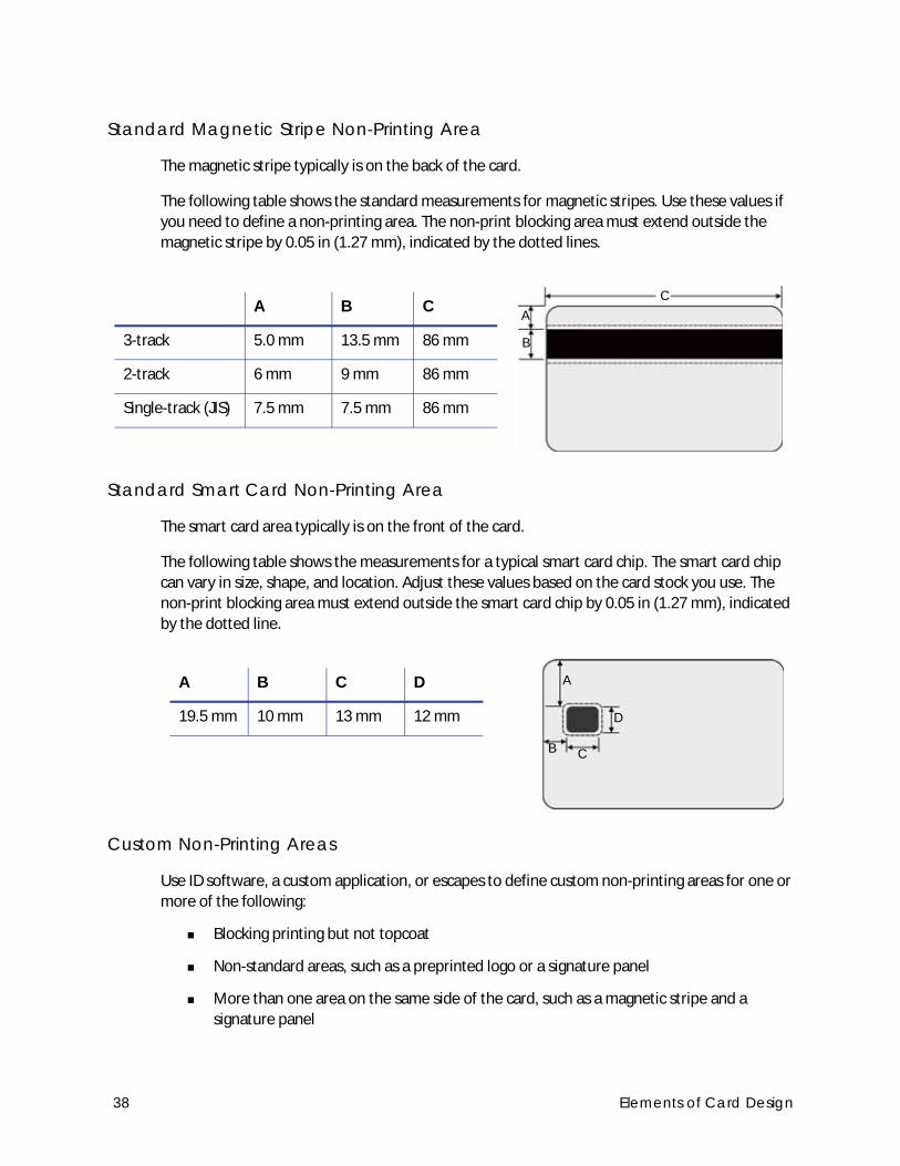
Standard Magnetic Stripe Non-Printing Area
The magnetic stripe typically is on the back of the card.
The following table shows the standard measurements for magnetic stripes. Use these values if
you need to define a non-printing area. The non-print blocking area must extend outside the
magnetic stripe by 0.05 in (1.27 mm), indicated by the dotted lines.
Standard Smart Card Non-Printing Area
The smart card area typically is on the front of the card.
The following table shows the measurements for a typical smart card chip. The smart card chip
can vary in size, shape, and location. Adjust these values based on the card stock you use. The
non-print blocking area must extend outside the smart card chip by 0.05 in (1.27 mm), indicated
by the dotted line.
Custom Non-Printing Areas
Use ID software, a custom application, or escapes to define custom non-printing areas for one or
more of the following:
Blocking printing but not topcoat
Non-standard areas, such as a preprinted logo or a signature panel
More than one area on the same side of the card, such as a magnetic stripe and a
signature panel
A B C
3-track 5.0 mm 13.5 mm 86 mm
2-track 6 mm 9 mm 86 mm
Single-track (JIS) 7.5 mm 7.5 mm 86 mm
C
A
B
A B C D
19.5 mm 10 mm 13 mm 12 mm
A
B C
D
38 Elements of Card Design
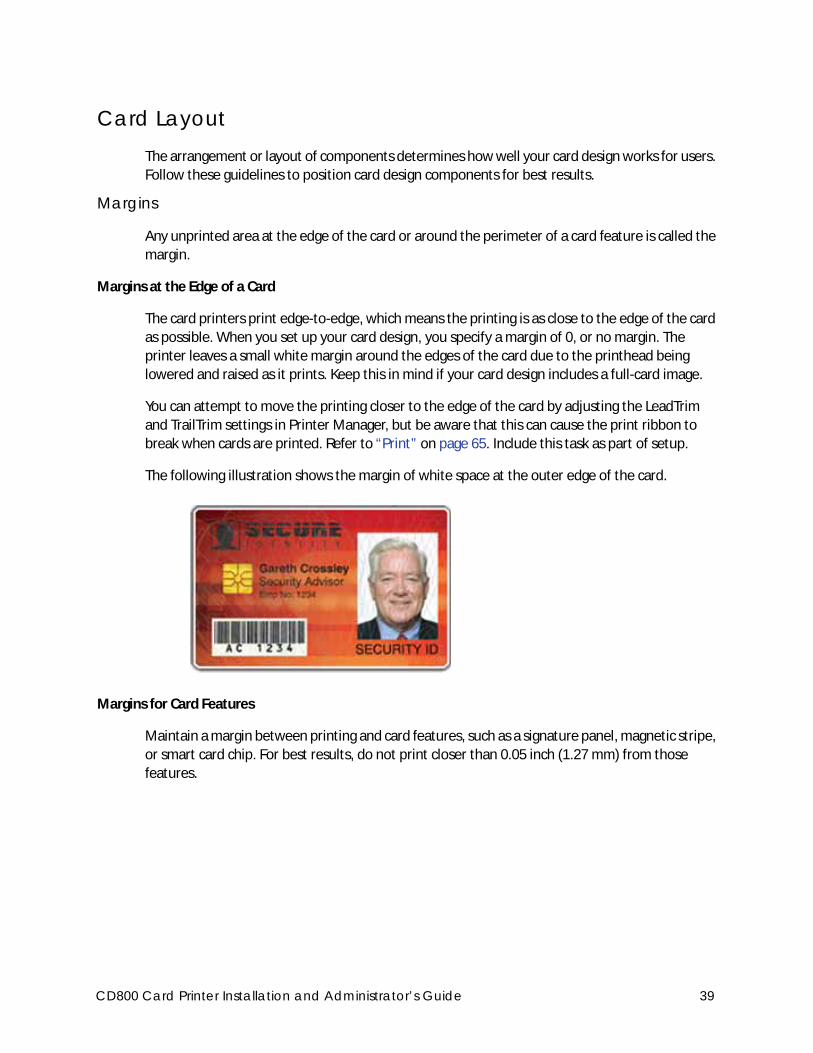
Card LayoutThe arrangement or layout of components determines how well your card design works for users.
Follow these guidelines to position card design components for best results.
Margins
Any unprinted area at the edge of the card or around the perimeter of a card feature is called the
margin.
Margins at the Edge of a Card
The card printers print edge-to-edge, which means the printing is as close to the edge of the card
as possible. When you set up your card design, you specify a margin of 0, or no margin. The
printer leaves a small white margin around the edges of the card due to the printhead being
lowered and raised as it prints. Keep this in mind if your card design includes a full-card image.
You can attempt to move the printing closer to the edge of the card by adjusting the LeadTrim
and TrailTrim settings in Printer Manager, but be aware that this can cause the print ribbon to
break when cards are printed. Refer to “Print” on page 65. Include this task as part of setup.
The following illustration shows the margin of white space at the outer edge of the card.
Margins for Card Features
Maintain a margin between printing and card features, such as a signature panel, magnetic stripe,
or smart card chip. For best results, do not print closer than 0.05 inch (1.27 mm) from those
features.
CD800 Card Printer Installation and Administrator’s Guide 39
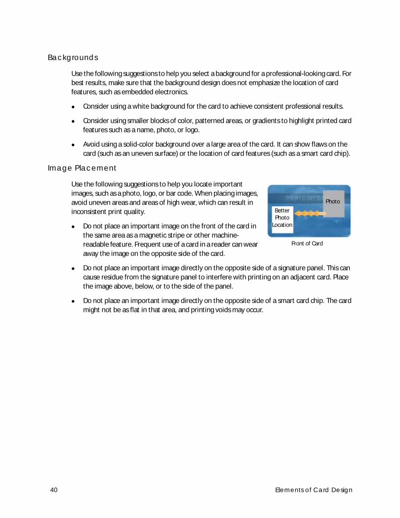
Backgrounds
Use the following suggestions to help you select a background for a professional-looking card. For
best results, make sure that the background design does not emphasize the location of card
features, such as embedded electronics.
Consider using a white background for the card to achieve consistent professional results.
Consider using smaller blocks of color, patterned areas, or gradients to highlight printed card
features such as a name, photo, or logo.
Avoid using a solid-color background over a large area of the card. It can show flaws on the
card (such as an uneven surface) or the location of card features (such as a smart card chip).
Image Placement
Use the following suggestions to help you locate important
images, such as a photo, logo, or bar code. When placing images,
avoid uneven areas and areas of high wear, which can result in
inconsistent print quality.
Do not place an important image on the front of the card in
the same area as a magnetic stripe or other machine-
readable feature. Frequent use of a card in a reader can wear
away the image on the opposite side of the card.
Do not place an important image directly on the opposite side of a signature panel. This can
cause residue from the signature panel to interfere with printing on an adjacent card. Place
the image above, below, or to the side of the panel.
Do not place an important image directly on the opposite side of a smart card chip. The card
might not be as flat in that area, and printing voids may occur.
Photo
Better Photo
Location
Front of Card
40 Elements of Card Design
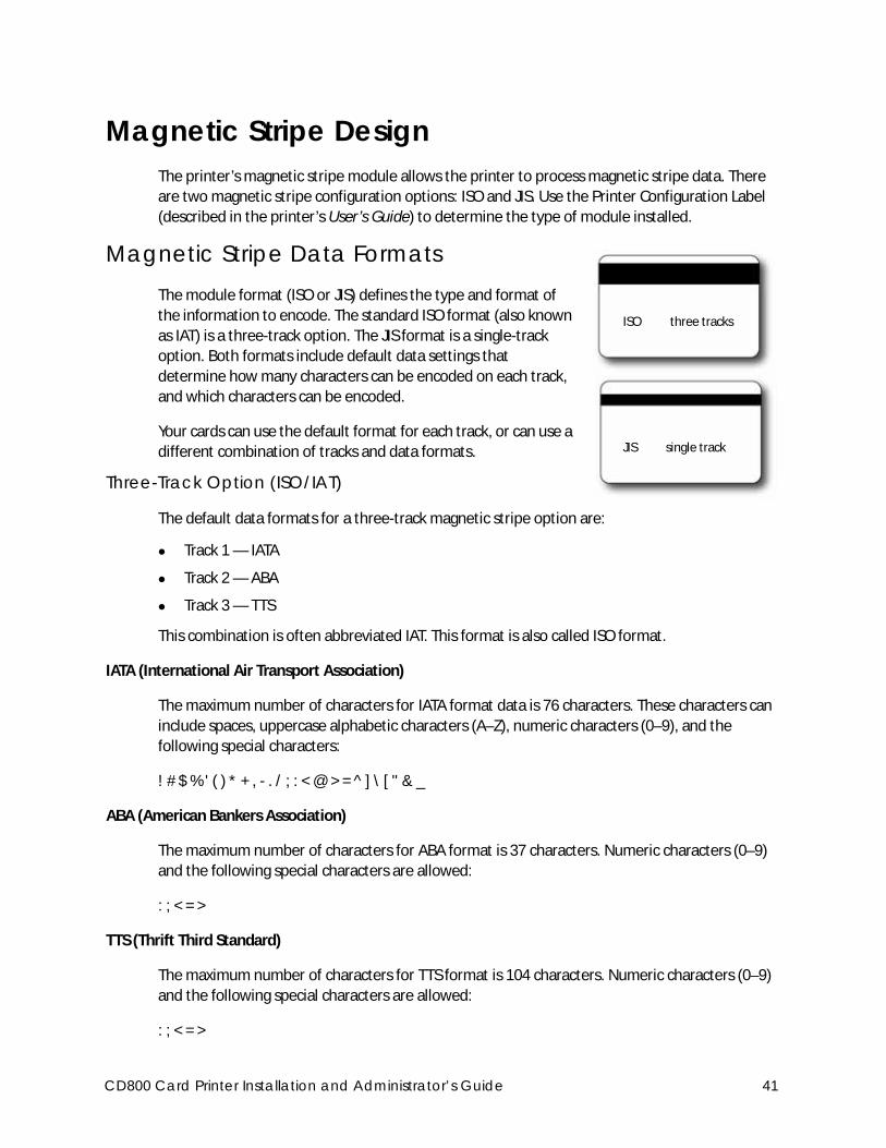
Magnetic Stripe DesignThe printer’s magnetic stripe module allows the printer to process magnetic stripe data. There
are two magnetic stripe configuration options: ISO and JIS. Use the Printer Configuration Label
(described in the printer’s User’s Guide) to determine the type of module installed.
Magnetic Stripe Data Formats The module format (ISO or JIS) defines the type and format of
the information to encode. The standard ISO format (also known
as IAT) is a three-track option. The JIS format is a single-track
option. Both formats include default data settings that
determine how many characters can be encoded on each track,
and which characters can be encoded.
Your cards can use the default format for each track, or can use a
different combination of tracks and data formats.
Three-Track Option (ISO/IAT)
The default data formats for a three-track magnetic stripe option are:
Track 1 — IATA
Track 2 — ABA
Track 3 — TTS
This combination is often abbreviated IAT. This format is also called ISO format.
IATA (International Air Transport Association)
The maximum number of characters for IATA format data is 76 characters. These characters can
include spaces, uppercase alphabetic characters (A–Z), numeric characters (0–9), and the
following special characters:
! # $ % ' ( ) * + , - . / ; : < @ > = ^ ] \ [ " & _
ABA (American Bankers Association)
The maximum number of characters for ABA format is 37 characters. Numeric characters (0–9)
and the following special characters are allowed:
: ; < = >
TTS (Thrift Third Standard)
The maximum number of characters for TTS format is 104 characters. Numeric characters (0–9)
and the following special characters are allowed:
: ; < = >
ISO three tracks
JIS single track
CD800 Card Printer Installation and Administrator’s Guide 41
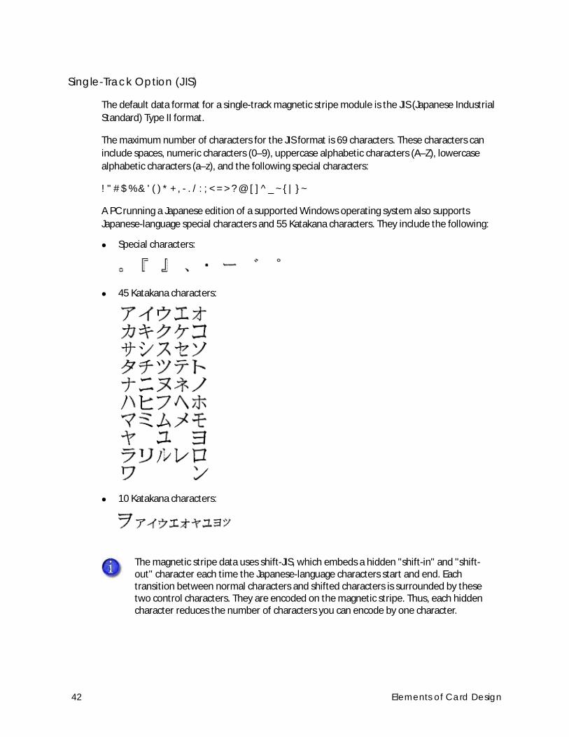
Single-Track Option (JIS)
The default data format for a single-track magnetic stripe module is the JIS (Japanese Industrial
Standard) Type II format.
The maximum number of characters for the JIS format is 69 characters. These characters can
include spaces, numeric characters (0–9), uppercase alphabetic characters (A–Z), lowercase
alphabetic characters (a–z), and the following special characters:
! " # $ % & ' ( ) * + , - . / : ; < = > ? @ [ ] ^ _ ~ { | } ~
A PC running a Japanese edition of a supported Windows operating system also supports
Japanese-language special characters and 55 Katakana characters. They include the following:
Special characters:
45 Katakana characters:
10 Katakana characters:
The magnetic stripe data uses shift-JIS, which embeds a hidden "shift-in" and "shift-out" character each time the Japanese-language characters start and end. Each transition between normal characters and shifted characters is surrounded by these two control characters. They are encoded on the magnetic stripe. Thus, each hidden character reduces the number of characters you can encode by one character.
42 Elements of Card Design
Magnetic Stripe CoercivityThe printer may require additional settings to match the coercivity of the card. When these
values are set they remain the same for all cards processed using the same design. The defaults
are set to standard ISO format and high coercivity. Refer to “MagStripeGeneral” on page 72 for
information about changing the coercivity.
The type of magnetic stripe cards you use must match the type of module (ISO or JIS) installed.
Test your printer to make sure that it is encoding magnetic stripe information properly.
Smart Card DesignSmart card processing differs from other types of card personalization. The “smart card” step of
personalization is controlled by an application that is separate from the rest of card
personalization.
The smart card reader can be factory-installed, or installed later as a field upgrade by a service
provider or value-added reseller. The printer configuration label (or a label attached at the time of
the field upgrade) shows the type of smart card reader installed. You can request additional
information about the smart card reader and the type of cards to use from your service provider
or value-added reseller.
Smart Card Processing RequirementsThe following items are required to personalize smart cards:
A smart card reader in the printer
A cable for the smart card port used (this cable is not needed for single-wire processing)
A card production application that is designed to work with the printer and the smart card
application
Smart cards that work with the reader in the printer
CD800 Card Printer Installation and Administrator’s Guide 43
Smart Card Codes on the Printer LabelThe configuration label includes codes that identify the type and model of the smart card module
installed in the printer. The following table lists the codes used on the configuration label.
The S1 value on the configuration label indicates that the printer has the basic smart card
components installed. Basic components include the mounting hardware only. An integrator
must install a contactless reader.
If the Sx value is included in the configuration code, the printer has the basic components of an
S1, plus the appropriate interface installed.
Code on Label Type of Smart Card Module
S1 Integrator Contactless
S3 HID pcProx Contactless
S4 iCLASS Read Contactless
S5 iCLASS Read/Write Contactless
S6 DUALi Standard
S7 DUALi Single Wire
S8 DUALi Single Wire Sony Felica
S9 GEMPC USB / pcProx Dual
S10 Contact Station
S11 Identive Dual Interface Reader
S12 pcProx Plus Dual Frequency
S13 DUALi Single Wire Large Memory
The smart card readers available may vary by printer model. Contact your authorized dealer for more information.
44 Elements of Card Design
Single-Wire Smart CardSingle-wire smart card processing allows a single USB or Ethernet connection with the printer to
carry data for both smart card personalization and printing.
The single-wire smart card feature is available to an application through the Windows Driver
Software Development Kit (SDK), or through your card personalization software.
Required components for single-wire smart card are the same as for other smart card systems
except as noted.
Settings for Card Design in Printer ManagerPrinter Manager contains card design settings that managers and service providers can use to set
up card production. The card design settings include magnetic stripe setup and smart card
testing. Printer Manager also contains troubleshooting features such as a log file that can track all
processes of a card job. Service providers can use the information in the log file to troubleshoot
and relay information when troubleshooting card processing issues. Refer to Chapter 3: "Printer
Manager” for more information.
The single-wire smart card programming interface is similar, but not identical, to the PC/SC standard. Applications using PC/SC to personalize smart cards require modification to use the single-wire smart card interface.
CD800 Card Printer Installation and Administrator’s Guide 45

46 Elements of Card Design
Chapter 3: Printer Manager
This section describes Printer Manager, the Datacard web interface
available to users, administrators, and service providers.
Printer ManagerPrinter Manager is a browser-based interface that displays information about the printer. System
administrators and service providers can use Printer Manager to fine-tune card appearance, set
advanced options, and troubleshoot printing problems. You can access Printer Manager using an
Internet browser and the IP address of the printer.
Printer Manager includes different user access levels that control the type of information that can
be viewed. You can choose from three user access levels to perform a variety of basic and
advanced tasks: WebUser, WebAdmin, and WebService.
CD800 Card Printer Installation and Administrator’s Guide 47
Printer Manager User Access LevelsThe Username field controls the level of access to information and settings that correspond to
the user’s job responsibility.
WebUser
WebUser access allows users to view information and change a limited amount of values. The
WebUser access level typically is used by the person responsible for printing cards. Other
responsibilities can include cleaning the printer, ordering printer supplies, or printing a daily or
weekly log of card production.
The WebUser access level displays four menu selections: Status, Printer Setting, Maintenance,
and Log Out.
WebAdmin
WebAdmin access allows an administrator to set up a test card and make minor adjustments to
the printer. The WebAdmin user has access to configuration options and the use of diagnostics
tools for troubleshooting. The WebAdmin user also can specify a password (using the Printer
Settings > Update Password option) for WebUser access-level users.
In a card production environment, the WebAdmin access-level user typically sets up the card
design, verifies communication with external data sources, and tracks printer activity and
performance.
WebService
WebService access has all of the above adjustments with additional access to adjust offsets.
The WebService user typically is an Entrust Datacard-trained service provider.
Access Printer ManagerThe initial Printer Manager screen allows users to log on with a user name and password that
determine their user access level. The user access level determines which menu items, options,
and adjustments are available.
1. Make sure that the printer's LCD panel displays Ready.
2. Access Printer Manager in one of the following ways:
a. If you use the Card Printer Driver, open the Printer Properties window for the printer and
select the Printer Status tab.
b. Click Configure Printer to launch Printer Manager in your default browser.
OR
48 Printer Manager
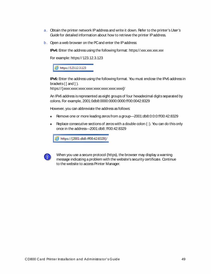
a. Obtain the printer network IP address and write it down. Refer to the printer’s User’s
Guide for detailed information about how to retrieve the printer IP address.
b. Open a web browser on the PC and enter the IP address:
IPv4: Enter the address using the following format: https://xxx.xxx.xxx.xxx
For example: https://123.12.3.123
IPv6: Enter the address using the following format. You must enclose the IPv6 address in
brackets ( [ and ] ).
https://[xxxx:xxxx:xxxx:xxxx:xxxx:xxxx:xxxx:xxxx]/
An IPv6 address is represented as eight groups of four hexadecimal digits separated by
colons. For example, 2001:0db8:0000:0000:0000:ff00:0042:8329
However, you can abbreviate the address as follows:
Remove one or more leading zeros from a group—2001:db8:0:0:0:ff00:42:8329
Replace consecutive sections of zeros with a double colon (::). You can do this only
once in the address—2001:db8::ff00:42:8329
When you use a secure protocol (https), the browser may display a warning message indicating a problem with the website’s security certificate. Continue to the website to access Printer Manager.
CD800 Card Printer Installation and Administrator’s Guide 49
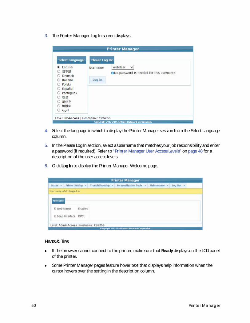
3. The Printer Manager Log In screen displays.
4. Select the language in which to display the Printer Manager session from the Select Language
column.
5. In the Please Log In section, select a Username that matches your job responsibility and enter
a password (if required). Refer to “Printer Manager User Access Levels” on page 48 for a
description of the user access levels.
6. Click Log In to display the Printer Manager Welcome page.
HINTS & TIPS
If the browser cannot connect to the printer, make sure that Ready displays on the LCD panel
of the printer.
Some Printer Manager pages feature hover text that displays help information when the
cursor hovers over the setting in the description column.
50 Printer Manager
Printer Manager SettingsThe printer is shipped with recommended settings in Printer Manager. You may need to change
these settings to customize the printer for your site. Printer Manager provides access to the
printer settings.
Many of the Printer Manager menu options display the Set Current and Restore Default buttons.
Set Current saves any changed settings on the displayed page. When you change a value and
click Set Current, the printer uses the new settings until the default values are restored. If you
exit a page without clicking Set Current, your changes are not applied.
Restore Default restores the default settings to the values on the displayed page.
Print a Printer Manager PageUse your Internet browser Print option to print the information from any Printer Manager page to
a paper printer.
Select File > Print from your Internet browser’s main menu.
If the printed page does not display all the information from the Printer Manager, select File >
Print Preview in your Internet browser to scale the image to fit the paper.
Use Printer ManagerThe following sections describe how to use the options on the Printer Manager menus that are
available to WebUser and WebAdmin access-level users. For information about settings available
to the WebService access level, contact your service provider.
If you enter a value outside the allowed range for a setting, the settings are not updated and a message displays asking you to correct your entry.
The options available in Printer Manager are determined by the printer model and the options installed on the printer. The Printer Manager options described in the following sections may not be available for all printers.
CD800 Card Printer Installation and Administrator’s Guide 51
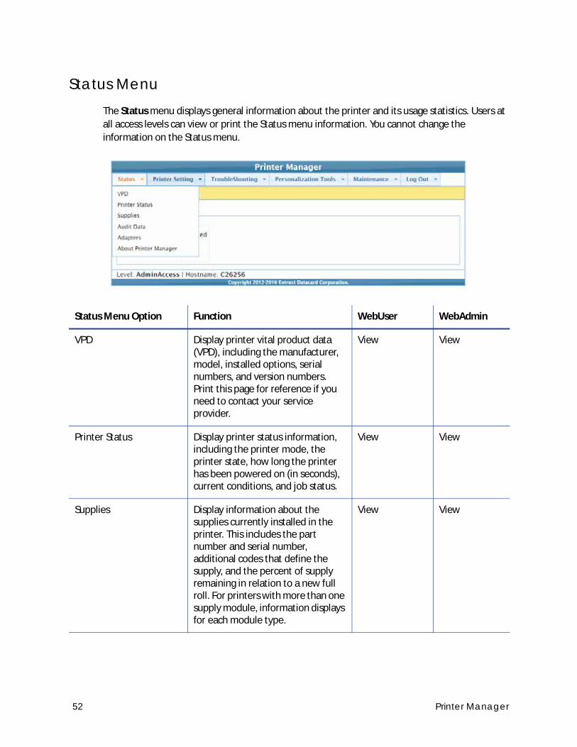
Status MenuThe Status menu displays general information about the printer and its usage statistics. Users at
all access levels can view or print the Status menu information. You cannot change the
information on the Status menu.
Status Menu Option Function WebUser WebAdmin
VPD Display printer vital product data (VPD), including the manufacturer, model, installed options, serial numbers, and version numbers. Print this page for reference if you need to contact your service provider.
View View
Printer Status Display printer status information, including the printer mode, the printer state, how long the printer has been powered on (in seconds), current conditions, and job status.
View View
Supplies Display information about the supplies currently installed in the printer. This includes the part number and serial number, additional codes that define the supply, and the percent of supply remaining in relation to a new full roll. For printers with more than one supply module, information displays for each module type.
View View
52 Printer Manager
Audit Data Display card printer usage data, including card counts (both resettable—shown with an r as the first letter of the name—and non-resettable counts) and error reporting collected by the printer. This page acts as a general overview for all the counters and can be useful to track card production activity and problem history.
View View
Adapters Display information about the IP addresses configured for the printer. The printer can have an IPv4 address and multiple IPv6 addresses configured concurrently. The page shows the IP address, network mask (or IPv6 prefix), gateway address, and MAC address for each adapter.
View View
About Printer Manager Display the Printer Manager software version and copyright information.
View View
Status Menu Option Function WebUser WebAdmin
CD800 Card Printer Installation and Administrator’s Guide 53
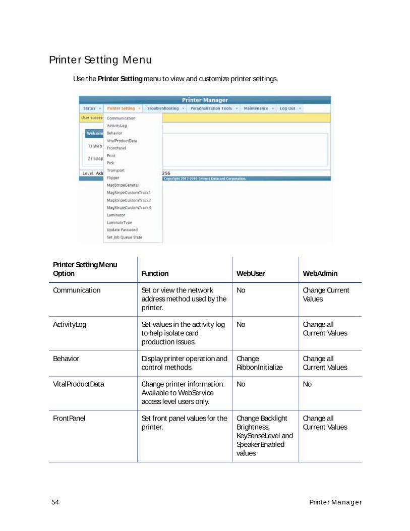
Printer Setting MenuUse the Printer Setting menu to view and customize printer settings.
Printer Setting Menu Option Function WebUser WebAdmin
Communication Set or view the network address method used by the printer.
No Change Current Values
ActivityLog Set values in the activity log to help isolate card production issues.
No Change all Current Values
Behavior Display printer operation and control methods.
Change RibbonInitialize
Change all Current Values
VitalProductData Change printer information. Available to WebService access level users only.
No No
FrontPanel Set front panel values for the printer.
Change Backlight Brightness, KeySenseLevel and SpeakerEnabled values
Change all Current Values
54 Printer Manager
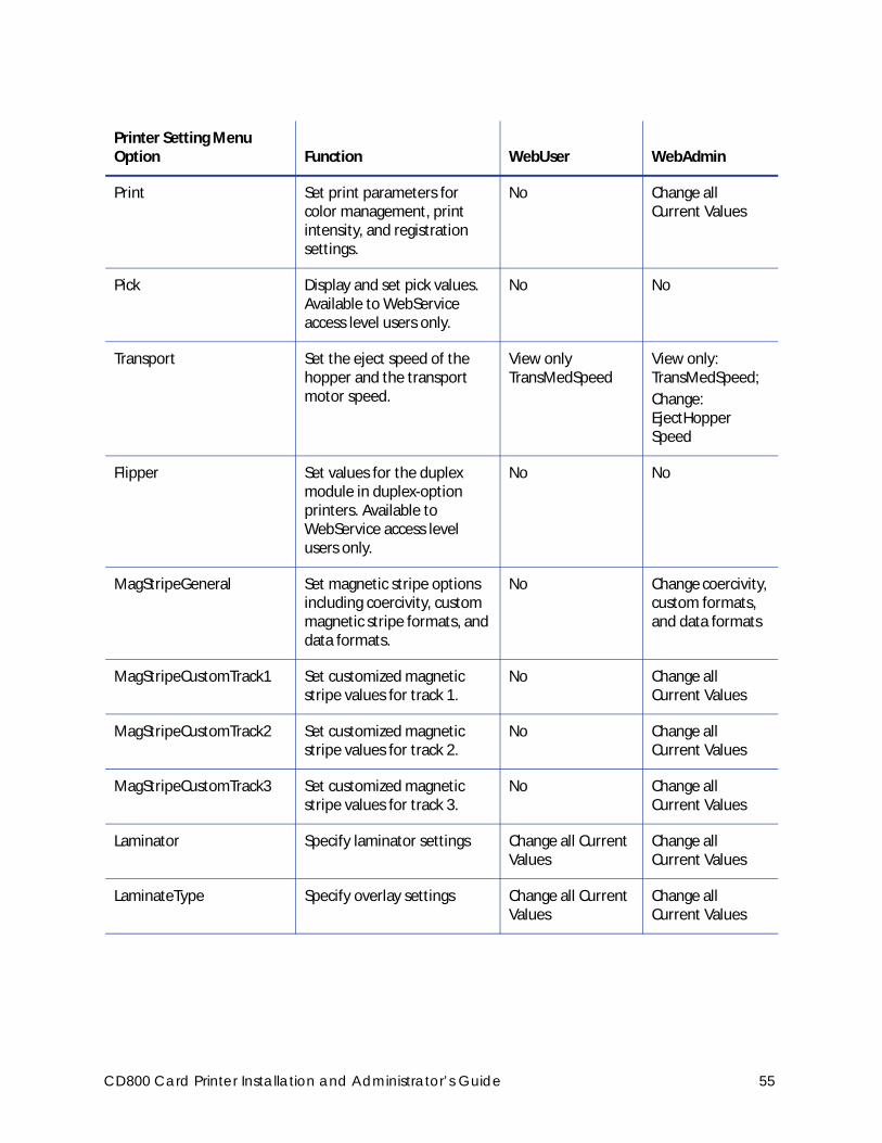
Print Set print parameters for color management, print intensity, and registration settings.
No Change all Current Values
Pick Display and set pick values. Available to WebService access level users only.
No No
Transport Set the eject speed of the hopper and the transport motor speed.
View only TransMedSpeed
View only: TransMedSpeed;
Change: EjectHopper Speed
Flipper Set values for the duplex module in duplex-option printers. Available to WebService access level users only.
No No
MagStripeGeneral Set magnetic stripe options including coercivity, custom magnetic stripe formats, and data formats.
No Change coercivity, custom formats, and data formats
MagStripeCustomTrack1 Set customized magnetic stripe values for track 1.
No Change all Current Values
MagStripeCustomTrack2 Set customized magnetic stripe values for track 2.
No Change all Current Values
MagStripeCustomTrack3 Set customized magnetic stripe values for track 3.
No Change all Current Values
Laminator Specify laminator settings Change all Current Values
Change all Current Values
LaminateType Specify overlay settings Change all Current Values
Change all Current Values
Printer Setting Menu Option Function WebUser WebAdmin
CD800 Card Printer Installation and Administrator’s Guide 55
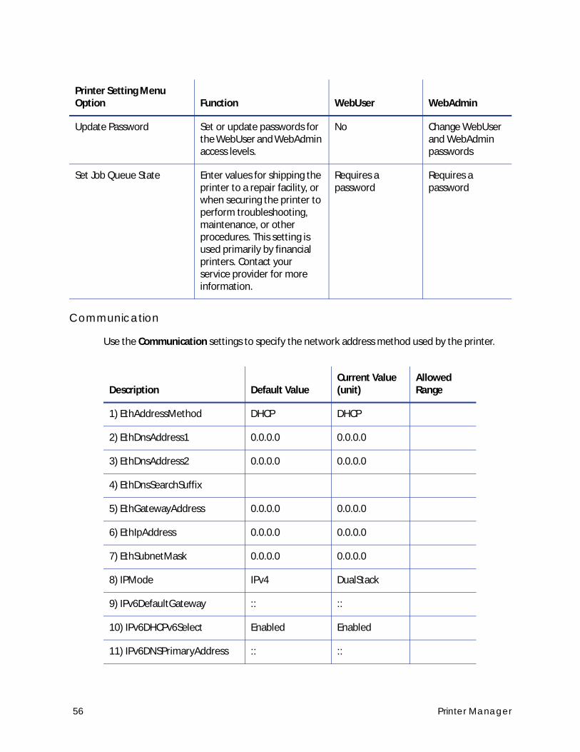
Communication
Use the Communication settings to specify the network address method used by the printer.
Update Password Set or update passwords for the WebUser and WebAdmin access levels.
No Change WebUser and WebAdmin passwords
Set Job Queue State Enter values for shipping the printer to a repair facility, or when securing the printer to perform troubleshooting, maintenance, or other procedures. This setting is used primarily by financial printers. Contact your service provider for more information.
Requires a password
Requires a password
Description Default ValueCurrent Value (unit)
Allowed Range
1) EthAddressMethod DHCP DHCP
2) EthDnsAddress1 0.0.0.0 0.0.0.0
3) EthDnsAddress2 0.0.0.0 0.0.0.0
4) EthDnsSearchSuffix
5) EthGatewayAddress 0.0.0.0 0.0.0.0
6) EthIpAddress 0.0.0.0 0.0.0.0
7) EthSubnetMask 0.0.0.0 0.0.0.0
8) IPMode IPv4 DualStack
9) IPv6DefaultGateway :: ::
10) IPv6DHCPv6Select Enabled Enabled
11) IPv6DNSPrimaryAddress :: ::
Printer Setting Menu Option Function WebUser WebAdmin
56 Printer Manager
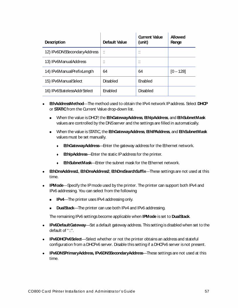
EthAddressMethod—The method used to obtain the IPv4 network IP address. Select DHCP
or STATIC from the Current Value drop-down list.
When the value is DHCP, the EthGatewayAddress, EthIpAddress, and EthSubnetMask
values are controlled by the DNS server and the settings are filled in automatically.
When the value is STATIC, the EthGatewayAddress, EthIPAddress, and EthSubnetMask
values must be set manually.
EthGatewayAddress—Enter the gateway address for the Ethernet network.
EthIpAddress—Enter the static IP address for the printer.
EthSubnetMask—Enter the subnet mask for the Ethernet network.
EthDnsAddress1, EthDnsAddress2, EthDnsSearchSuffix—These settings are not used at this
time.
IPMode—Specify the IP mode used by the printer. The printer can support both IPv4 and
IPv6 addressing. You can select from the following
IPv4—The printer uses IPv4 addressing only.
DualStack—The printer can use both IPv4 and IPv6 addressing.
The remaining IPv6 settings become applicable when IPMode is set to DualStack.
IPv6DefaultGateway—Set a default gateway address. This setting is disabled when set to the
default of “::”.
IPv6DHCPv6Select—Select whether or not the printer obtains an address and stateful
configuration from a DHCPv6 server. Disable this setting if a DHCPv6 server is not present.
IPv6DNSPrimaryAddress, IPv6DNSSecondaryAddress—These settings are not used at this
time.
12) IPv6DNSSecondaryAddress :: ::
13) IPv6ManualAddress :: ::
14) IPv6ManualPrefixLength 64 64 [0 – 128]
15) IPv6ManualSelect Disabled Enabled
16) IPv6StatelessAddrSelect Enabled Disabled
Description Default ValueCurrent Value (unit)
Allowed Range
CD800 Card Printer Installation and Administrator’s Guide 57
IPv6ManualAddress—Enter the IPv6 address using the following format:
xxxx:xxxx:xxxx:xxxx:xxxx:xxxx:xxxx:xxxx
Refer to “Access Printer Manager” on page 48 for more information about entering an IPv6
address.
IPV6ManualSelect must be set to Enabled for the printer to use this setting.
IPv6ManualPrefixLength—Specify the IPv6 manual subnet prefix length. IPv6 addresses
consist of two parts. The prefix length indicates the boundary between the subnet to which
the host is connected and the device ID in the IPv6 manual address, starting from the left
end. The default value is 64.
IPv6ManualSelect—Enable the printer to use the manual address specified in
IPv6ManualAddress. If this setting is disabled, the manual address information specified for
the printer is retained, but is not used.
IPv6StatelessAddrSelect—Enable the printer to allow the router to provide one or more
network prefixes used for stateless automatic address configuration (SLAAC).
To modify the Communications settings:
1. Enter your changes in the Current Value fields.
2. Click Set Current to apply the changes.
3. Log out of Printer Manager, and then restart it for the changes to take effect.
58 Printer Manager
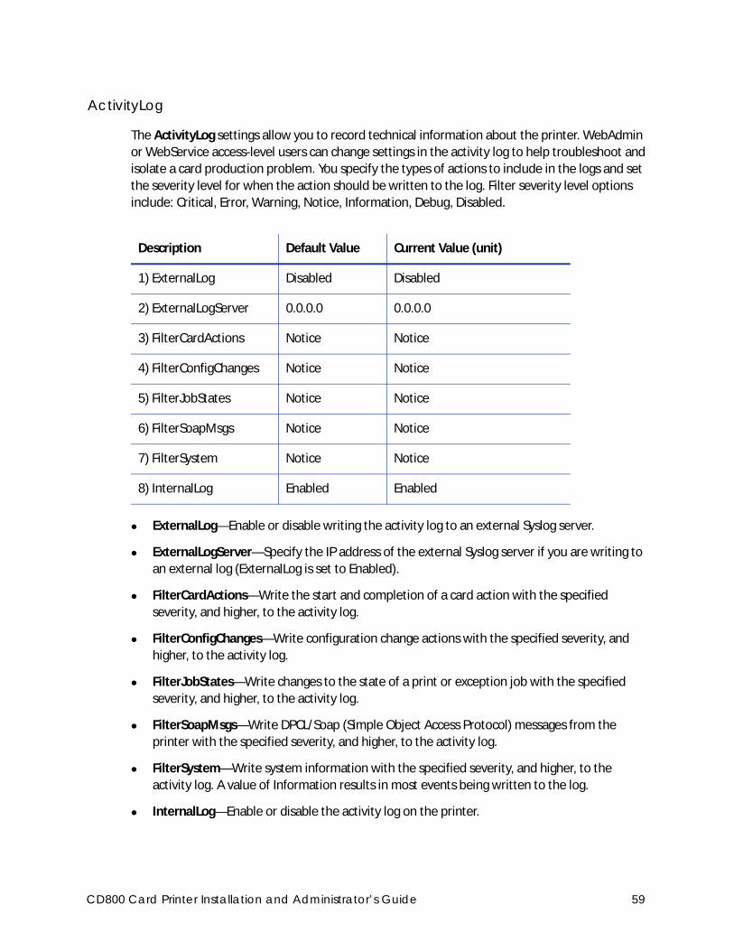
ActivityLog
The ActivityLog settings allow you to record technical information about the printer. WebAdmin
or WebService access-level users can change settings in the activity log to help troubleshoot and
isolate a card production problem. You specify the types of actions to include in the logs and set
the severity level for when the action should be written to the log. Filter severity level options
include: Critical, Error, Warning, Notice, Information, Debug, Disabled.
ExternalLog—Enable or disable writing the activity log to an external Syslog server.
ExternalLogServer—Specify the IP address of the external Syslog server if you are writing to
an external log (ExternalLog is set to Enabled).
FilterCardActions—Write the start and completion of a card action with the specified
severity, and higher, to the activity log.
FilterConfigChanges—Write configuration change actions with the specified severity, and
higher, to the activity log.
FilterJobStates—Write changes to the state of a print or exception job with the specified
severity, and higher, to the activity log.
FilterSoapMsgs—Write DPCL/Soap (Simple Object Access Protocol) messages from the
printer with the specified severity, and higher, to the activity log.
FilterSystem—Write system information with the specified severity, and higher, to the
activity log. A value of Information results in most events being written to the log.
InternalLog—Enable or disable the activity log on the printer.
Description Default Value Current Value (unit)
1) ExternalLog Disabled Disabled
2) ExternalLogServer 0.0.0.0 0.0.0.0
3) FilterCardActions Notice Notice
4) FilterConfigChanges Notice Notice
5) FilterJobStates Notice Notice
6) FilterSoapMsgs Notice Notice
7) FilterSystem Notice Notice
8) InternalLog Enabled Enabled
CD800 Card Printer Installation and Administrator’s Guide 59
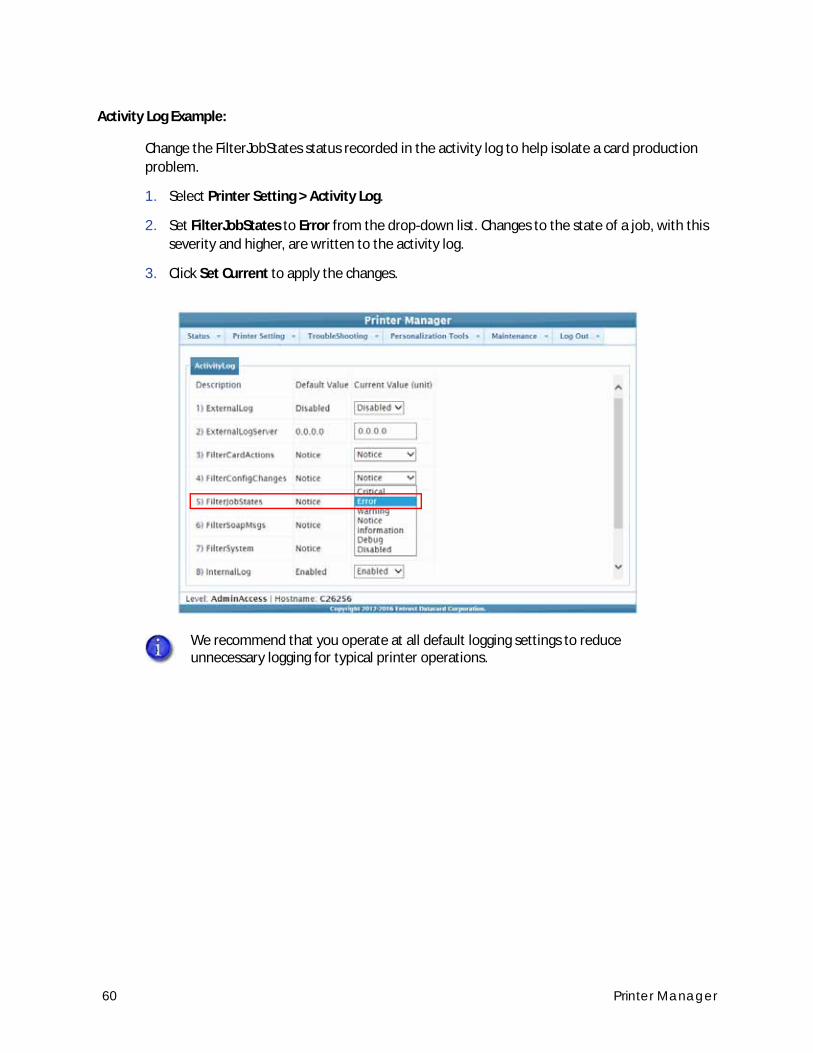
Activity Log Example:
Change the FilterJobStates status recorded in the activity log to help isolate a card production
problem.
1. Select Printer Setting > Activity Log.
2. Set FilterJobStates to Error from the drop-down list. Changes to the state of a job, with this
severity and higher, are written to the activity log.
3. Click Set Current to apply the changes.
We recommend that you operate at all default logging settings to reduce unnecessary logging for typical printer operations.
60 Printer Manager
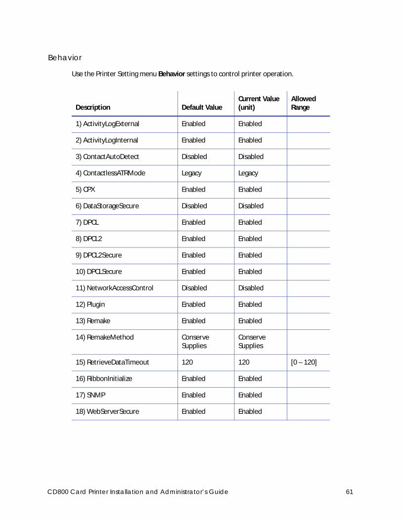
Behavior
Use the Printer Setting menu Behavior settings to control printer operation.
Description Default ValueCurrent Value (unit)
Allowed Range
1) ActivityLogExternal Enabled Enabled
2) ActivityLogInternal Enabled Enabled
3) ContactAutoDetect Disabled Disabled
4) ContactlessATRMode Legacy Legacy
5) CPX Enabled Enabled
6) DataStorageSecure Disabled Disabled
7) DPCL Enabled Enabled
8) DPCL2 Enabled Enabled
9) DPCL2Secure Enabled Enabled
10) DPCLSecure Enabled Enabled
11) NetworkAccessControl Disabled Disabled
12) Plugin Enabled Enabled
13) Remake Enabled Enabled
14) RemakeMethod ConserveSupplies
ConserveSupplies
15) RetrieveDataTimeout 120 120 [0 – 120]
16) RibbonInitialize Enabled Enabled
17) SNMP Enabled Enabled
18) WebServerSecure Enabled Enabled
CD800 Card Printer Installation and Administrator’s Guide 61
Update Current Values as needed, and then click Set Current to apply changes.
ActivityLogExternal—Enable or disable writing the activity log to an external server.
ActivityLogInternal—Enable or disable the internal activity log.
ContactAutoDetect—This setting supports legacy smart card clients. It overrides the smart
card protocol sent by the client to the printer and uses SCARD_PROTOCOL_T0_OR_T1. The
setting is set to Disabled by default.
ContactlessATRMode—Select the default ATR mode for the DUALi contactless smart card
reader. The possible values are:
Vendor—Uses the ATR mode specified by the vendor. The generated ATR may not be
compatible with all smart card applications or card types.
PCSC—Uses the PC/SC protocol to generate the ATR.
CCID—Uses the CCID protocol to generate the ATR.
Legacy—Uses the ATR mode currently in use by the reader. This is the default value.
AppSpecifies—Allows the smart card application to control the ATR mode.
CPX—Enable or disable the CPX communications protocol used by some Datacard systems.
DataStorageSecure—Allows you to encrypt the data stored on the printer’s internal SD card.
Encrypting data provides extra security in the event the printer is stolen or disassembled and
the SD card removed. Once data is encrypted, there is no impact on performance of the
printer.
Enabled—Encrypts the printer data. Restart the printer after you select Enabled. The
printer encrypts the data during the startup process. Encrypting the internally stored
data takes approximately 20 minutes. the printer cannot be used until the encryption
operation completes.
Disabled—Disables encryption of the internal printer data. When you select Disabled
and restart the printer, the data is decrypted during printer shutdown. The decryption
process takes approximately 20 minutes. The printer restarts when the decryption is
complete. Disabled is the default setting for DataStorageSecure.
DPCL—Enable or disable DPCL command access to the printer through the non-secure port.
DPCL must remain enabled when you use the XPS Card Printer Driver.
DPCL2—Enable or disable DPCL2 command access to the printer through the non-secure
port.
A smart card application may specify to receive the ATR in a different format regardless of this setting. However, when the printer restarts, the smart card reader returns to the setting specified here. Consider whether you want to specify the format on a job-by-job basis or modify the Printer Manager setting to use the desired ATR format.
62 Printer Manager
DPCL2Secure—Enable or disable DPCL2 command access to the printer through the secure
port.
DPCLSecure—Enable or disable DPCL command access to the printer through the secure
port.
NetworkAccessControl—Enable or disable network access control.
Plugin—Enable or disable the plugin feature for the printer to access an installed plug-in. This
setting is used for OpenCard-enabled printers.
Remake—Enable or disable card remakes. If Remake is set to Enabled and a print request
fails, the print request is tried again with a new card. A card is retried only once.
RemakeMethod—Select the card remake method. This setting does not display if Remake is
set to Disabled.
Select ConserveSupplies to reprint the card out of queue order.
Select PreserveOrder to reprint the card in queue order.
RetrieveDataTimeout—Specify the time period during which card data can be retrieved. You
can specify from 0 to 120 seconds. If the Current Value is 0, data is not retrieved.
RibbonInitialize—Enable or disable initialization of the ribbon when the printer is powered
on.
SNMP—Enable or disable SNMP Service.
WebServerSecure—Enable or disable access to Printer Manager (the web server) through
the secure port.
VitalProductData
The VitalProductData settings allow WebService access level users to change information about
the printer or system in specific circumstances. Contact your service provider should it become
necessary to modify the VitalProductData settings.
Caution: Do not disable the web server. If the web server is disabled, you cannot launch Printer Manager and configuration changes cannot be made. To reverse this action, you must contact Entrust Datacard. To restrict access for the WebAdmin access level, select Printer Setting > Update Password and specify a password.
CD800 Card Printer Installation and Administrator’s Guide 63
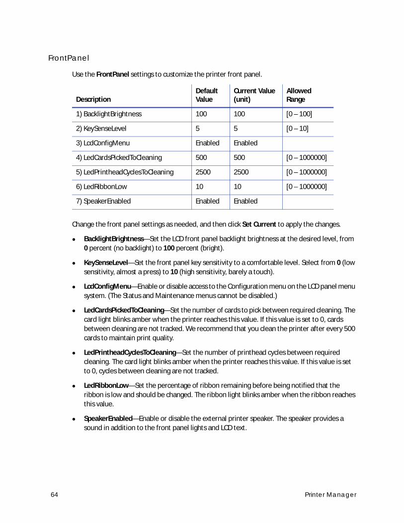
FrontPanel
Use the FrontPanel settings to customize the printer front panel.
Change the front panel settings as needed, and then click Set Current to apply the changes.
BacklightBrightness—Set the LCD front panel backlight brightness at the desired level, from
0 percent (no backlight) to 100 percent (bright).
KeySenseLevel—Set the front panel key sensitivity to a comfortable level. Select from 0 (low
sensitivity, almost a press) to 10 (high sensitivity, barely a touch).
LcdConfigMenu—Enable or disable access to the Configuration menu on the LCD panel menu
system. (The Status and Maintenance menus cannot be disabled.)
LedCardsPickedToCleaning—Set the number of cards to pick between required cleaning. The
card light blinks amber when the printer reaches this value. If this value is set to 0, cards
between cleaning are not tracked. We recommend that you clean the printer after every 500
cards to maintain print quality.
LedPrintheadCyclesToCleaning—Set the number of printhead cycles between required
cleaning. The card light blinks amber when the printer reaches this value. If this value is set
to 0, cycles between cleaning are not tracked.
LedRibbonLow—Set the percentage of ribbon remaining before being notified that the
ribbon is low and should be changed. The ribbon light blinks amber when the ribbon reaches
this value.
SpeakerEnabled—Enable or disable the external printer speaker. The speaker provides a
sound in addition to the front panel lights and LCD text.
DescriptionDefault Value
Current Value (unit)
Allowed Range
1) BacklightBrightness 100 100 [0 – 100]
2) KeySenseLevel 5 5 [0 – 10]
3) LcdConfigMenu Enabled Enabled
4) LedCardsPickedToCleaning 500 500 [0 – 1000000]
5) LedPrintheadCyclesToCleaning 2500 2500 [0 – 1000000]
6) LedRibbonLow 10 10 [0 – 1000000]
7) SpeakerEnabled Enabled Enabled
64 Printer Manager
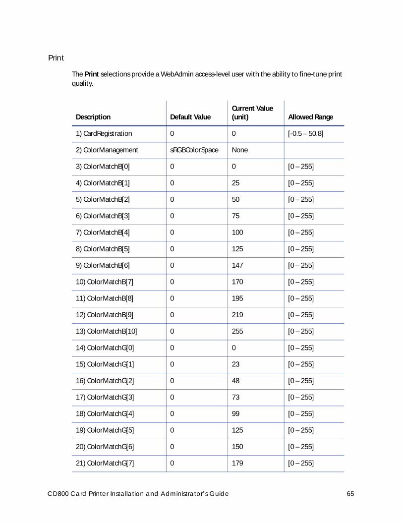
The Print selections provide a WebAdmin access-level user with the ability to fine-tune print
quality.
Description Default ValueCurrent Value (unit) Allowed Range
1) CardRegistration 0 0 [-0.5 – 50.8]
2) ColorManagement sRGBColorSpace None
3) ColorMatchB[0] 0 0 [0 – 255]
4) ColorMatchB[1] 0 25 [0 – 255]
5) ColorMatchB[2] 0 50 [0 – 255]
6) ColorMatchB[3] 0 75 [0 – 255]
7) ColorMatchB[4] 0 100 [0 – 255]
8) ColorMatchB[5] 0 125 [0 – 255]
9) ColorMatchB[6] 0 147 [0 – 255]
10) ColorMatchB[7] 0 170 [0 – 255]
11) ColorMatchB[8] 0 195 [0 – 255]
12) ColorMatchB[9] 0 219 [0 – 255]
13) ColorMatchB[10] 0 255 [0 – 255]
14) ColorMatchG[0] 0 0 [0 – 255]
15) ColorMatchG[1] 0 23 [0 – 255]
16) ColorMatchG[2] 0 48 [0 – 255]
17) ColorMatchG[3] 0 73 [0 – 255]
18) ColorMatchG[4] 0 99 [0 – 255]
19) ColorMatchG[5] 0 125 [0 – 255]
20) ColorMatchG[6] 0 150 [0 – 255]
21) ColorMatchG[7] 0 179 [0 – 255]
CD800 Card Printer Installation and Administrator’s Guide 65
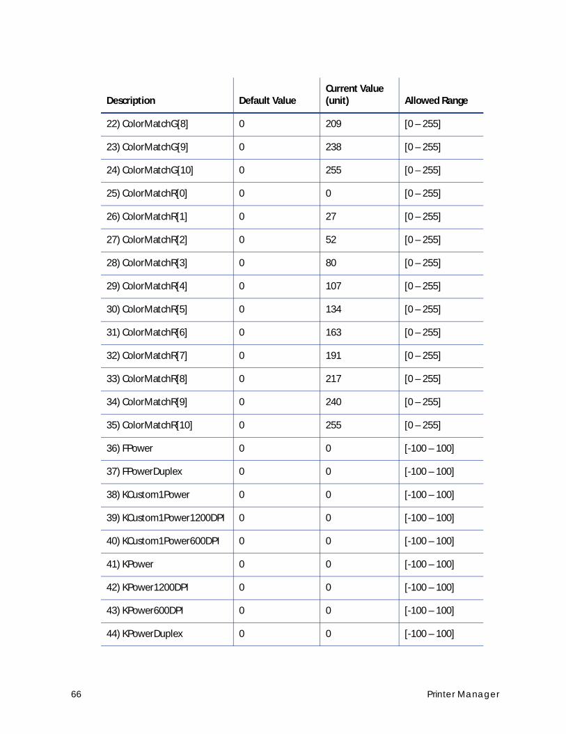
22) ColorMatchG[8] 0 209 [0 – 255]
23) ColorMatchG[9] 0 238 [0 – 255]
24) ColorMatchG[10] 0 255 [0 – 255]
25) ColorMatchR[0] 0 0 [0 – 255]
26) ColorMatchR[1] 0 27 [0 – 255]
27) ColorMatchR[2] 0 52 [0 – 255]
28) ColorMatchR[3] 0 80 [0 – 255]
29) ColorMatchR[4] 0 107 [0 – 255]
30) ColorMatchR[5] 0 134 [0 – 255]
31) ColorMatchR[6] 0 163 [0 – 255]
32) ColorMatchR[7] 0 191 [0 – 255]
33) ColorMatchR[8] 0 217 [0 – 255]
34) ColorMatchR[9] 0 240 [0 – 255]
35) ColorMatchR[10] 0 255 [0 – 255]
36) FPower 0 0 [-100 – 100]
37) FPowerDuplex 0 0 [-100 – 100]
38) KCustom1Power 0 0 [-100 – 100]
39) KCustom1Power1200DPI 0 0 [-100 – 100]
40) KCustom1Power600DPI 0 0 [-100 – 100]
41) KPower 0 0 [-100 – 100]
42) KPower1200DPI 0 0 [-100 – 100]
43) KPower600DPI 0 0 [-100 – 100]
44) KPowerDuplex 0 0 [-100 – 100]
Description Default ValueCurrent Value (unit) Allowed Range
66 Printer Manager
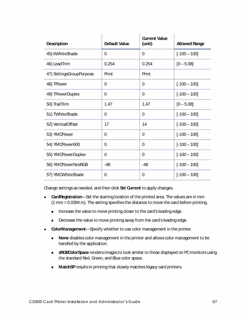
Change settings as needed, and then click Set Current to apply changes.
CardRegistration—Set the starting location of the printed area. The values are in mm
(1 mm = 0.0394 in). The setting specifies the distance to move the card before printing.
Increase the value to move printing closer to the card’s leading edge.
Decrease the value to move printing away from the card’s leading edge.
ColorManagement—Specify whether to use color management in the printer.
None disables color management in the printer and allows color management to be
handled by the application.
sRGBColorSpace renders images to look similar to those displayed on PC monitors using
the standard Red, Green, and Blue color space.
MatchSP results in printing that closely matches legacy card printers.
45) KWhiteShade 0 0 [-100 – 100]
46) LeadTrim 0.254 0.254 [0 – 5.08]
47) SettingsGroupPurpose Print Print
48) TPower 0 0 [-100 – 100]
49) TPowerDuplex 0 0 [-100 – 100]
50) TrailTrim 1.47 1.47 [0 – 5.08]
51) TWhiteShade 0 0 [-100 – 100]
52) VerticalOffset 17 14 [-100 – 100]
53) YMCPower 0 0 [-100 – 100]
54) YMCPower600 0 0 [-100 – 100]
55) YMCPowerDuplex 0 0 [-100 – 100]
56) YMCPowerNosRGB -48 -48 [-100 – 100]
57) YMCWhiteShade 0 0 [-100 – 100]
Description Default ValueCurrent Value (unit) Allowed Range
CD800 Card Printer Installation and Administrator’s Guide 67

ColorMatchB[0–10], ColorMatchG[0–10], ColorMatchR[0–10]—The ColorMatch settings for
Blue(B), Green(G), and Red (R), are used by the printer to make sure that the print color
output is consistent for all ribbon types. Each value has been calibrated so that the colors
that print on a card are the same for every ribbon type. We recommend that you do not
change these settings except under the guidance of your service provider.
FPower—Modify the print intensity for the F panel of UV ribbon.
Increase the value to make UV printing more defined on the card.
Decrease the value to reduce the UV intensity or prevent frequent ribbon breaks when
printing with a UV ribbon.
FPowerDuplex—Modify the print intensity for the back side F panel of UV ribbon.
Increase the value to make UV printing more defined on the card.
Decrease the value to reduce the UV intensity or to prevent frequent ribbon breaks when
printing with a UV panel.
KCustom1Power—Modify the print intensity for the non-black monochrome panel of MT-KT
(ST-KT or GT-KT) ribbon.
Increase the value to make single-color printing thicker and more defined on the card.
Decrease the value to reduce the monochrome intensity or to prevent frequent ribbon
breaks when printing with the M panel.
KCustom1Power1200DPI—Modify the print intensity at 1200 dpi for the non-black
monochrome panel of MT-KT (ST-KT or GT-KT) ribbon.
Increase the value to make single-color printing thicker and more defined on the card.
Decrease the value to reduce the monochrome intensity or to prevent frequent ribbon
breaks when printing with the M panel.
KCustom1Power600DPI—Modify the print intensity at 600 dpi for the non-black
monochrome panel of MT-KT (ST-KT or GT-KT) ribbon.
Increase the value to make single-color printing thicker and more defined on the card.
Decrease the value to reduce the monochrome intensity or to prevent frequent ribbon
breaks when printing with the M panel.
If any of the ColorMatch settings are changed, they cannot be restored by clicking Restore Defaults. To restore the color match settings to their original values, set ColorMatchR[10] to 0 and click Set Current. Power off the printer, and then power it on again. This restores all 33 of the ColorMatch settings to their original calibrated values.
68 Printer Manager
KPower—Modify the print intensity for K (single-color) panel or K (single-color) ribbon.
Increase the value to make single-color printing thicker and more defined on the card.
Decrease the value for crisp bar codes or to prevent frequent ribbon breaks when
printing with the K panel.
KPower1200DPI—Modify the print intensity at 1200 dpi for the K panel or K ribbon.
Increase the value to make single-color printing thicker and more defined on the card.
Decrease the value for crisp bar codes or to prevent frequent ribbon breaks when
printing with the K panel.
KPower600DPI—Modify the print intensity at 600 dpi for the K panel or K ribbon.
Increase the value to make single-color printing thicker and more defined on the card.
Decrease the value for crisp bar codes or to prevent frequent ribbon breaks when
printing with the K panel.
KPowerDuplex—Modify the print intensity for the back-side K panel and K ribbons.
Increase the value to make single-color printing thicker and more defined on the card.
Decrease the value for crisp bar codes or to prevent frequent ribbon breaks when
printing with the K panel.
KWhiteShade—Modify the amount of power applied to the printhead to reduce ribbon
friction without transferring material. Decrease the value if material transfers to the card
when it should not.
LeadTrim—Modify the number of millimeters to remove from the leading edge of a full-size
image to keep it within the print area (1 mm = 0.0394 in. or about 11.8 dot rows).
SettingsGroupPurpose—State the purpose of a settings group. Group names are not
changeable. Use this option to identify the reason for creating a settings group.
TPower—Modify the intensity of the T (topcoat) ribbon panel.
Increase the value to make printed topcoat thicker or more uniform.
Decrease the value to prevent frequent ribbon breaks while printing the topcoat.
TPowerDuplex—Modify the intensity of the back-side T (topcoat) ribbon panel.
Increase the value to make printed topcoat thicker or more uniform.
Decrease the value to prevent ribbon breaks while printing the topcoat.
CD800 Card Printer Installation and Administrator’s Guide 69

TrailTrim—Modify the number of millimeters to remove from the trailing edge of a full-size
image to keep it within the print area (1 mm = 0.0394 in. or about 11.8 dot rows).
Increase the value to lengthen the printed area.
Decrease the value to shorten the printed area.
TWhiteShade—Modify the amount of power applied to the printhead to reduce ribbon
friction without transferring material. Decrease the value if material transfers to the card
when it should not.
VerticalOffset—Modify the image placement on the card. Use this setting to align printing
with the long edges of the card. Specify the number of printhead dots to shift printing toward
the top or left side of the card. You cannot change the number of dots between the long
edges of the card.
YMCPower—Modify the intensity of the YMC (color) ribbon panels.
Increase the value to make the color printing more intense.
Decrease the value to reduce the color intensity or to prevent frequent ribbon breaks
when printing colors.
YMCPower600—Modify the print intensity at 600 dpi for the YMC (color) ribbon panels.
Increase the value to make the color printing more intense.
Decrease the value to reduce the color intensity or to prevent frequent ribbon breaks
when printing colors.
YMCPowerDuplex—Modify the intensity of the back-side YMC (color) ribbon panels.
Increase the value to make the color printing more intense.
Decrease the value to reduce the color intensity or to prevent frequent ribbon breaks
when printing colors.
YMCPowerNosRGB—Modify the intensity when you are printing without the sRGB color
mode.
Increase the value to make the non-sRGB color darker
Decrease the value if using non-sRGB color mode to prevent overly dark printing or
ribbon wrinkles or tears.
YMCWhiteShade—Modify the amount of power applied to the printhead to reduce ribbon
friction without transferring material. Decrease the value if unprinted or white areas of the
card have color applied to them and should not.
70 Printer Manager
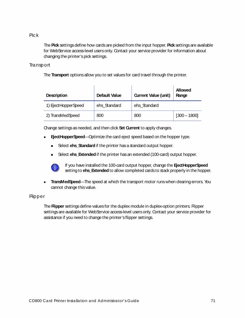
Pick
The Pick settings define how cards are picked from the input hopper. Pick settings are available
for WebService access-level users only. Contact your service provider for information about
changing the printer’s pick settings.
Transport
The Transport options allow you to set values for card travel through the printer.
Change settings as needed, and then click Set Current to apply changes.
EjectHopperSpeed—Optimize the card eject speed based on the hopper type.
Select ehs_Standard if the printer has a standard output hopper.
Select ehs_Extended if the printer has an extended (100-card) output hopper.
TransMedSpeed—The speed at which the transport motor runs when clearing errors. You
cannot change this value.
Flipper
The Flipper settings define values for the duplex module in duplex-option printers. Flipper
settings are available for WebService access-level users only. Contact your service provider for
assistance if you need to change the printer’s flipper settings.
Description Default Value Current Value (unit)Allowed Range
1) EjectHopperSpeed ehs_Standard ehs_Standard
2) TransMedSpeed 800 800 [300 – 1800]
If you have installed the 100-card output hopper, change the EjectHopperSpeed setting to ehs_Extended to allow completed cards to stack properly in the hopper.
CD800 Card Printer Installation and Administrator’s Guide 71
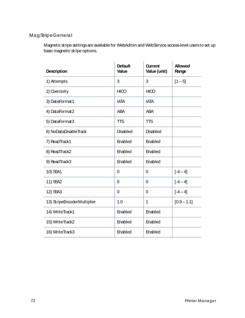
MagStripeGeneral
Magnetic stripe settings are available for WebAdmin and WebService access-level users to set up
basic magnetic stripe options.
DescriptionDefault Value
Current Value (unit)
Allowed Range
1) Attempts 3 3 [1 – 5]
2) Coercivity HICO HICO
3) DataFormat1 IATA IATA
4) DataFormat2 ABA ABA
5) DataFormat3 TTS TTS
6) NoDataDisableTrack Disabled Disabled
7) ReadTrack1 Enabled Enabled
8) ReadTrack2 Enabled Enabled
9) ReadTrack3 Enabled Enabled
10) SSA1 0 0 [-4 – 4]
11) SSA2 0 0 [-4 – 4]
12) SSA3 0 0 [-4 – 4]
13) StripeEncoderMultiplier 1.0 1 [0.9 – 1.1]
14) WriteTrack1 Enabled Enabled
15) WriteTrack2 Enabled Enabled
16) WriteTrack3 Enabled Enabled
72 Printer Manager

Change settings as needed, and then click Set Current to apply changes.
Attempts—Specify the number of attempts (automatic retries) the printer makes to encode
the magnetic stripe data. This value also is used for the number of times to attempt to read
magnetic stripe data.
If you set this number to a lower value, it increases the throughput of the printer but can
decrease the reliability of magnetic stripe encoding.
If you set the number to a higher value, it decreases the throughput of the printer but can
increase the reliability of magnetic stripe encoding.
A value of 1 means no retry attempts.
Coercivity—Select the coercivity setting that matches the cards you are using. Coercivity
measures the resistance of magnetic material to the removal of encoded data. High coercivity
(HICO) requires more electrical force to encode data and the data is more resistant to
magnetic interference. The choices are HICO, LOCO, NTT1, NTT2, NTT3.
DataFormat (1, 2, 3)—Specify the names of the data formats used for tracks 1, 2, and 3.
For single-track magnetic stripe encoding, set DataFormat1 to JIS and DataFormat2 and
DataFormat3 to NONE.
To use a custom data format, define the formats for tracks 1, 2, and/or 3 using the
MagStripeCustomTrack (1, 2, 3) settings and then set the corresponding DataFormat settings
to CUSTOM.
NoDataDisableTrack—Disable the magnetic stripe write head for a track if the track contains
no data. When this is disabled, any track that was not given data is erased.
ReadTrack (1, 2, 3)—Allow magnetic stripe read actions to read from tracks 1, 2, and 3.
SSA (1, 2, 3)—Set the start sentinel adjustment for tracks 1, 2, and 3. (SSA3 also sets the start
sentinel for a single track.) The start sentinel is encoded on the magnetic stripe immediately
before the first data character and indicates the beginning of data. Enter a value from -4 to 4.
StripeEncoderMultiplier—This value is information only and cannot be changed. It is
determined when an SSA test is run.
WriteTrack (1, 2, 3)—Allow magnetic stripe write actions to write to tracks 1, 2, and 3.
CD800 Card Printer Installation and Administrator’s Guide 73
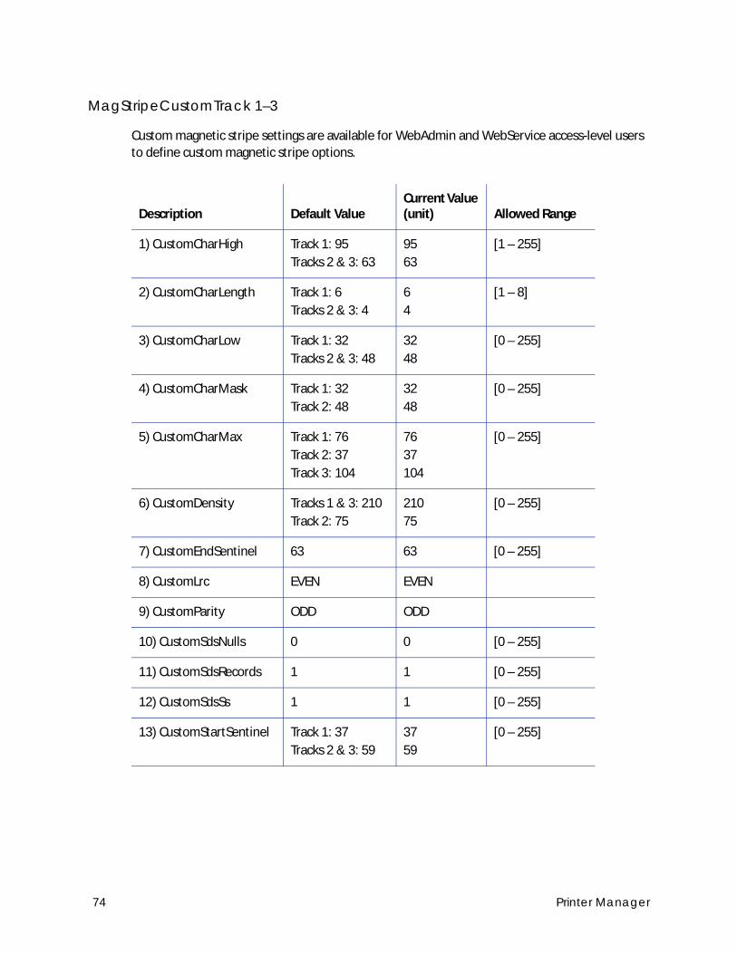
MagStripeCustomTrack 1–3
Custom magnetic stripe settings are available for WebAdmin and WebService access-level users
to define custom magnetic stripe options.
Description Default ValueCurrent Value (unit) Allowed Range
1) CustomCharHigh Track 1: 95
Tracks 2 & 3: 63
95
63
[1 – 255]
2) CustomCharLength Track 1: 6
Tracks 2 & 3: 4
6
4
[1 – 8]
3) CustomCharLow Track 1: 32
Tracks 2 & 3: 48
32
48
[0 – 255]
4) CustomCharMask Track 1: 32
Track 2: 48
32
48
[0 – 255]
5) CustomCharMax Track 1: 76
Track 2: 37
Track 3: 104
76
37
104
[0 – 255]
6) CustomDensity Tracks 1 & 3: 210
Track 2: 75
210
75
[0 – 255]
7) CustomEndSentinel 63 63 [0 – 255]
8) CustomLrc EVEN EVEN
9) CustomParity ODD ODD
10) CustomSdsNulls 0 0 [0 – 255]
11) CustomSdsRecords 1 1 [0 – 255]
12) CustomSdsSs 1 1 [0 – 255]
13) CustomStartSentinel Track 1: 37
Tracks 2 & 3: 59
37
59
[0 – 255]
74 Printer Manager
Change settings as needed, and then click Set Current to apply changes.
CustomCharHigh—Specify the numeric value of the highest ASCII character supported for
input data on the track.
CustomCharLength—Set the number of bits to represent one character of data on the track,
also called bits per character.
CustomCharLow—Specify the numeric value of the lowest ASCII character supported for
input data on the track.
CustomCharMask—Specify the mask value that is subtracted from the ASCII numeric value to
get the encoded value.
CustomCharMax—Specify the maximum number of data characters for the track. The value
does not include the start sentinel or end sentinel.
CustomDensity—Specify the number of data bits per inch of magnetic stripe media for the
track, also called bits per inch or bpi. Allowed values are 75 bpi or 210 bpi.
CustomEndSentinel—Specify the last character encoded, which identifies the end of
encoded data for the track.
CustomLrc—Specify a cumulative parity bit that is encoded after the end sentinel to provide
simple error checking.
CustomParity—Specify a character-level parity bit encoded after each character to provide
simple error checking.
CustomSdsNulls—The number of nulls between each copy of the data record. You should not
change this value.
CustomSdsRecords—The number of times to encode the data record. You should not change
this value.
CustomSdsSs—The number of start sentinels before each data record. You should not change
this value.
CustomStartSentinel—Specify the first character encoded, which identifies the start of the
encoded data for the track.
CD800 Card Printer Installation and Administrator’s Guide 75
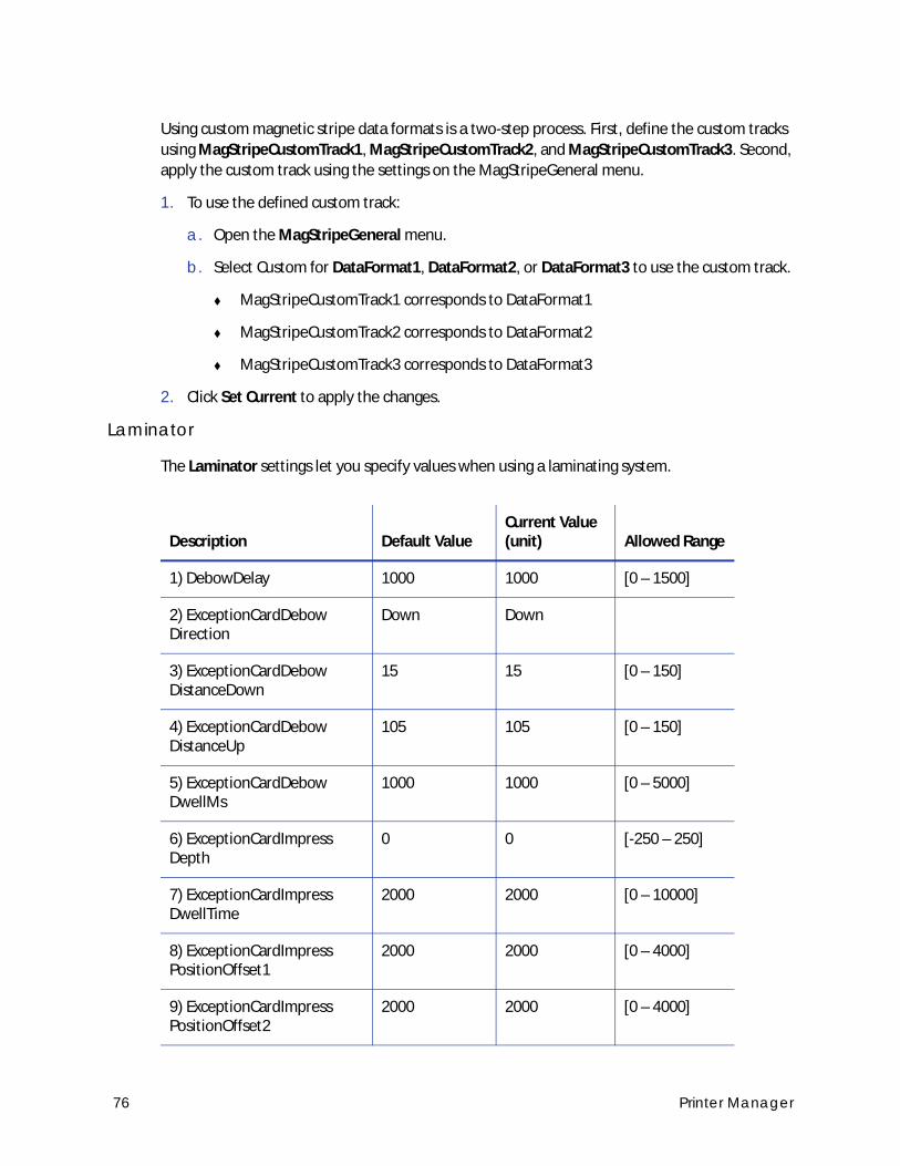
Using custom magnetic stripe data formats is a two-step process. First, define the custom tracks
using MagStripeCustomTrack1, MagStripeCustomTrack2, and MagStripeCustomTrack3. Second,
apply the custom track using the settings on the MagStripeGeneral menu.
1. To use the defined custom track:
a. Open the MagStripeGeneral menu.
b. Select Custom for DataFormat1, DataFormat2, or DataFormat3 to use the custom track.
MagStripeCustomTrack1 corresponds to DataFormat1
MagStripeCustomTrack2 corresponds to DataFormat2
MagStripeCustomTrack3 corresponds to DataFormat3
2. Click Set Current to apply the changes.
Laminator
The Laminator settings let you specify values when using a laminating system.
Description Default ValueCurrent Value (unit) Allowed Range
1) DebowDelay 1000 1000 [0 – 1500]
2) ExceptionCardDebow Direction
Down Down
3) ExceptionCardDebow DistanceDown
15 15 [0 – 150]
4) ExceptionCardDebow DistanceUp
105 105 [0 – 150]
5) ExceptionCardDebow DwellMs
1000 1000 [0 – 5000]
6) ExceptionCardImpress Depth
0 0 [-250 – 250]
7) ExceptionCardImpress DwellTime
2000 2000 [0 – 10000]
8) ExceptionCardImpress PositionOffset1
2000 2000 [0 – 4000]
9) ExceptionCardImpress PositionOffset2
2000 2000 [0 – 4000]
76 Printer Manager
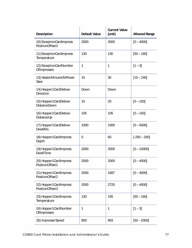
10) ExceptionCardImpress PositionOffset3
2000 2000 [0 – 4000]
11) ExceptionCardImpress Temperature
130 130 [50 – 160]
12) ExceptionCardNumber OfImpresses
1 1 [1 – 3]
13) HeaterMinutesToPower Save
15 30 [15 – 240]
14) Hopper1CardDebow Direction
Down Down
15) Hopper1CardDebow DistanceDown
15 20 [0 – 150]
16) Hopper1CardDebow DistanceUp
105 105 [0 – 150]
17) Hopper1CardDebow DwellMs
1000 1000 [0 – 5000]
18) Hopper1CardImpress Depth
0 60 [-250 – 250]
19) Hopper1CardImpress DwellTime
2000 2000 [0 – 10000]
20) Hopper1CardImpress PositionOffset1
2000 2000 [0 – 4000]
21) Hopper1CardImpress PositionOffset2
2000 1687 [0 – 4000]
22) Hopper1CardImpress PositionOffset3
2000 2725 [0 – 4000]
23) Hopper1CardImpress Temperature
130 155 [50 – 160]
24) Hopper1CardNumber OfImpresses
1 1 [1 – 3]
25) ImpresserSpeed 893 893 [50 – 2000]
Description Default ValueCurrent Value (unit) Allowed Range
CD800 Card Printer Installation and Administrator’s Guide 77
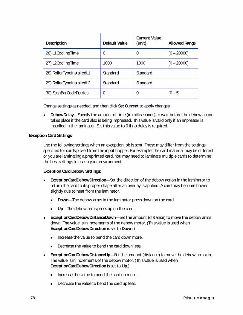
Change settings as needed, and then click Set Current to apply changes.
DebowDelay—Specify the amount of time (in milliseconds) to wait before the debow action
takes place if the card also is being impressed. This value is valid only if an impresser is
installed in the laminator. Set this value to 0 if no delay is required.
Exception Card Settings
Use the following settings when an exception job is sent. These may differ from the settings
specified for cards picked from the input hopper. For example, the card material may be different
or you are laminating a preprinted card. You may need to laminate multiple cards to determine
the best settings to use in your environment.
Exception Card Debow Settings:
ExceptionCardDebowDirection—Set the direction of the debow action in the laminator to
return the card to its proper shape after an overlay is applied. A card may become bowed
slightly due to heat from the laminator.
Down—The debow arms in the laminator press down on the card.
Up—The debow arms press up on the card.
ExceptionCardDebowDistanceDown—Set the amount (distance) to move the debow arms
down. The value is in increments of the debow motor. (This value is used when
ExceptionCardDebowDirection is set to Down.)
Increase the value to bend the card down more.
Decrease the value to bend the card down less.
ExceptionCardDebowDistanceUp—Set the amount (distance) to move the debow arms up.
The value is in increments of the debow motor. (This value is used when
ExceptionCardDebowDirection is set to Up.)
Increase the value to bend the card up more.
Decrease the value to bend the card up less.
26) L1CoolingTime 0 0 [0 – 20000]
27) L2CoolingTime 1000 1000 [0 – 20000]
28) RollerTypeInstalledL1 Standard Standard
29) RollerTypeInstalledL2 Standard Standard
30) ScanBarCodeRetries 0 0 [0 – 5]
Description Default ValueCurrent Value (unit) Allowed Range
78 Printer Manager
ExceptionCardDebowDwellMs—Set the time, in milliseconds, the debow action is applied to
a card. The default is 2000 ms (2 seconds).
Increase the value to apply the debow action longer.
Decrease the value to apply the debow action for less time.
Exception Card Impresser Settings:
ExceptionCardImpressDepth—Set the depth of the impression on a card. The value is in
steps of the impresser punch.
Increase the value to deepen the impression.
Decrease the value to lessen the impression.
ExceptionCardImpressDwellTime—Set the time, in milliseconds, that the impresser remains
in contact with the card. The default is 2000 ms (2 seconds).
Increase the value to allow the impresser to remain on the card longer.
Decrease the value to impress the card for a shorter time.
ExceptionCardImpressPositionOffset1—Set the distance from the trailing edge of the card to
the center of the first impression on the card.
Increase the offset value to increase the distance of the impression from the trailing edge
of the card.
Decrease the offset value to decrease the distance of the impression from the trailing
edge of the card.
ExceptionCardImpressPositionOffset2—Set the distance from the trailing edge of the card to
the center of the second impression on the card.
Increase the offset value to increase the distance of the impression from the trailing edge
of the card.
Decrease the offset value to decrease the distance of the impression from the trailing
edge of the card.
ExceptionCardImpressPositionOffset3—Set the distance from the trailing edge of the card to
the center of the third impression on the card.
Increase the offset value to increase the distance of the impression from the trailing edge
of the card.
Decrease the offset value to decrease the distance of the impression from the trailing
edge of the card.
You may need to adjust the card impress depth value based on the card material and overlay type used.
CD800 Card Printer Installation and Administrator’s Guide 79
ExceptionCardImpressTemperature—Set the temperature of the impresser punch (in
degrees Celsius).
Increase the value to increase the temperature of the impresser punch.
Decrease the value to decrease the temperature of the impresser punch.
ExceptionCardNumberOfImpresses—Enter the number of impressions to be stamped on the
card. The impresser can stamp up to three impressions in a row on the left, center, or right
part of the card.
HeaterMinutesToPowerSave—Set the number of minutes before the laminator and
impresser heaters are turned off. After the specified number of minutes, the heaters are
allowed to cool down. Using power save requires a warm-up period before the laminator is
ready to laminate cards again. The front panel LCD displays the message Busy Warming up
and a percentage that indicates the status of the heaters.
Hopper 1 Settings
Use the following settings to specify values for cards picked from the input hopper. Set up the
input hopper for the most commonly used card type.
Hopper 1 Debow Settings:
Hopper1DebowDirection—Set the direction of the debow action in the laminator to return
the card to its proper shape after an overlay is applied. A card may become bowed slightly
due to heat from the laminator.
Down—The debow arms in the laminator press down on the card.
Up—The debow arms press up on the card.
Hopper1DebowDistanceDown—Set the amount (distance) to move the debow arms down.
The value is in increments of the debow motor. (This value is used when
Hopper1DebowDirection is set to Down.)
Increase the value to bend the card down more.
Decrease the value to bend the card down less.
Hopper1DebowDistanceUp—Set the amount (distance) to move the debow arms up. The
value is in increments of the debow motor. (This value is used when
Hopper1DebowDirection is set to Up.)
Increase the value to bend the card up more.
Decrease the value to bend the card up less.
80 Printer Manager

Hopper1DebowDwellMs—Set the time, in milliseconds, the debow action is applied to a
card. The default is 2000 ms (2 seconds).
Increase the value to apply the debow action longer.
Decrease the value to apply the debow action for less time.
Hopper 1 Impresser Settings:
Hopper1ImpressDepth—Set the depth of the impression on a card. The value is in steps of
the impresser punch.
Increase the value to deepen the impression.
Decrease the value to lessen the impression.
Hopper1ImpressDwellTime—Set the time, in milliseconds, that the impresser remains in
contact with the card. The default is 2000 ms (2 seconds).
Increase the value to allow the impresser to remain on the card longer.
Decrease the value to impress the card for a shorter time.
Hopper1ImpressPositionOffset1—Set the distance from the trailing edge of the card to the
center of the first impression on the card.
Increase the offset value to increase the distance of the impression from the trailing edge
of the card.
Decrease the offset value to decrease the distance of the impression from the trailing
edge of the card.
Hopper1ImpressPositionOffset2—Set the distance from the trailing edge of the card to the
center of the second impression on the card.
Increase the offset value to increase the distance of the impression from the trailing edge
of the card.
Decrease the offset value to decrease the distance of the impression from the trailing
edge of the card.
Hopper1ImpressPositionOffset3—Set the distance from the trailing edge of the card to the
center of the third impression on the card.
Increase the offset value to increase the distance of the impression from the trailing edge
of the card.
Decrease the offset value to decrease the distance of the impression from the trailing
edge of the card.
You may need to adjust the card impress depth value based on the card material and overlay type used.
CD800 Card Printer Installation and Administrator’s Guide 81
Hopper1ImpressTemperature—Set the temperature of the impresser punch (in degrees
Celsius).
Increase the value to increase the temperature of the impresser punch.
Decrease the value to decrease the temperature of the impresser punch.
Hopper1NumberOfImpresses—Enter the number of impressions to be stamped on the card.
The impresser can stamp up to three impressions in a row on the left, center, or right part of
the card.
ImpresserSpeed—Set the speed of the impresser motor. The value is in increments of the
motor.
Increase the value to increase the speed of the impresser motor.
Decrease the value to decrease the speed of the impresser motor.
L1CoolingTime—Specify the time, in milliseconds, to wait for the card to cool after applying
the overlay in the L1 laminator. The default is 0 (no delay).
L2CoolingTime—Specify the time, in milliseconds, to wait for the card to cool after applying
the overlay in the L2 laminator before proceeding to the L1 laminator. The default is 1000 ms
(1 second). Enter 0 to turn off the delay.
RollerTypeInstalledL1—Specify the type of roller installed in the L1 laminator. The options
are Standard, Rubber, or Custom.
RollerTypeInstalledL2—Specify the type of roller installed in the L2 laminator. The options
are Standard, Rubber, or Custom.
ScanBarCodeRetries—Specify the number of times the bar code scanner should attempt to
read a bar code on a serialized overlay. If the read fails, the next read attempt advances the
overlay to the next usable bar code on the overlay. This applies only to laminators that have
the optional bar code scanner installed.
82 Printer Manager
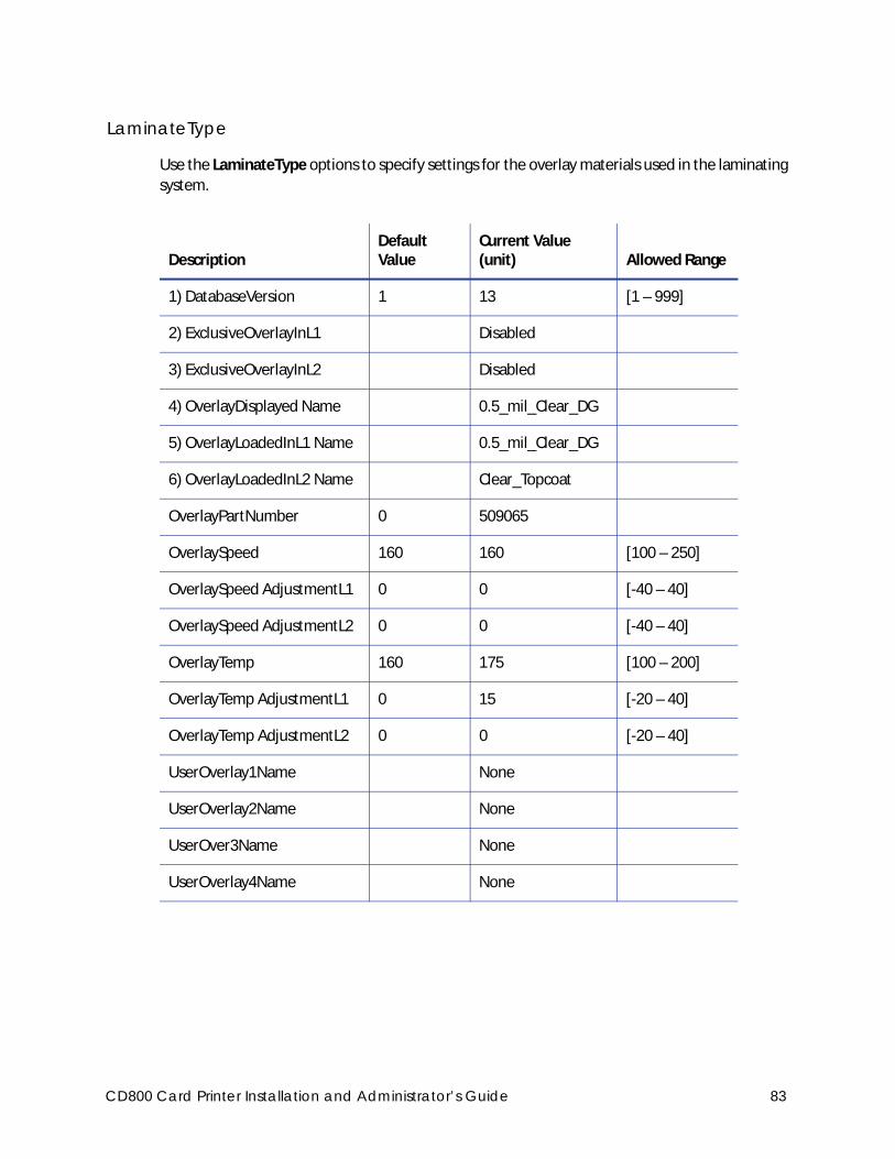
LaminateType
Use the LaminateType options to specify settings for the overlay materials used in the laminating
system.
DescriptionDefault Value
Current Value (unit) Allowed Range
1) DatabaseVersion 1 13 [1 – 999]
2) ExclusiveOverlayInL1 Disabled
3) ExclusiveOverlayInL2 Disabled
4) OverlayDisplayed Name 0.5_mil_Clear_DG
5) OverlayLoadedInL1 Name 0.5_mil_Clear_DG
6) OverlayLoadedInL2 Name Clear_Topcoat
OverlayPartNumber 0 509065
OverlaySpeed 160 160 [100 – 250]
OverlaySpeed AdjustmentL1 0 0 [-40 – 40]
OverlaySpeed AdjustmentL2 0 0 [-40 – 40]
OverlayTemp 160 175 [100 – 200]
OverlayTemp AdjustmentL1 0 15 [-20 – 40]
OverlayTemp AdjustmentL2 0 0 [-20 – 40]
UserOverlay1Name None
UserOverlay2Name None
UserOver3Name None
UserOverlay4Name None
CD800 Card Printer Installation and Administrator’s Guide 83
Change settings as needed, and then click Set Current to apply changes.
DatabaseVersion—The version number of the overlay database currently installed in the
laminator. This field is information only. The overlay database is an XML file that contains the
supported overlay types and allows the laminator to identify the type of overlay loaded in
each cartridge. You can download an updated laminator supplies overlay database from the
Drivers and Downloads page at www.datacard.com. The downloaded zip file contains
instructions and a utility that updates the laminator.
ExclusiveOverlayInL1, ExclusiveOverlayInL2—Use these settings to enforce that a specified
overlay type is loaded in the L1 or L2 laminators. The default value is Disabled, which allows
any overlay to be loaded in the laminator cartridges. If you select an overlay name, the
named overlay must be loaded in the specified cartridge or the job is canceled and a supply
error is issued.
OverlayDisplayedName—Select the name of the overlay whose settings you want to change.
Click Set Current to apply the overlay selection. You must do this before making any changes
to the overlay settings.
The changes you make to the remainder of the settings on this page apply to the selected
overlay type. The settings apply whenever the named overlay is loaded in the laminator.
OverlayLoadedInL1Name—The name of the overlay type loaded in the L1 laminator
cartridge. This information is obtained from the supply roll and cannot be changed. If the
overlay name is the same as the overlay type selected in OverlayDisplayedName, the values
you specify to the settings on this page apply to the overlay. If the overlay name is not the
same, no changes are applied.
OverlayLoadedInL2Name—The name of the overlay type loaded in the L2 laminator
cartridge. This information is obtained from the supply roll and cannot be changed. If the
overlay name is the same as the overlay type selected in OverlayDisplayedName, the values
you specify to the settings on this page apply to the overlay. If the overlay name is not the
same, no changes are applied.
OverlayPartNumber—The part number of the overlay named in OverlayDisplayedName.
This field is obtained from the supply roll and cannot be changed.
OverlaySpeed—The default speed, in steps per second, at which to apply the overlay type
named in OverlayDisplayedName. This value is obtained from the supply roll and cannot be
changed. Make adjustments to the speed using the OverlaySpeedAdjustment settings.
OverlaySpeedAdjustmentL1, OverlaySpeedAdjustmentL2—Adjust the speed at which to
apply the overlay type named in OverlayDisplayedName when it is loaded in the specified
cartridge. The speed adjustment is measured in steps per second of the motor that moves
the card. Set the speed as the difference between the default speed value (shown in
OverlaySpeed) and speed you want to use. Decrease the speed to improve how the overlay
adheres to the card. For example, if the default is 160, and you want to set the speed to 150,
enter -10.
84 Printer Manager
OverlayTemp—The temperature at which to apply the overlay type named in
OverlayDisplayedName. This Current Value is obtained from the supply roll and cannot be
changed. Make adjustments to the temperature using the OverlayTempAdjustment settings.
OverlayTempAdjustmentL1, OverlayTempAdjustmentL2—Adjust the temperature at which
to apply the overlay type named in OverlayDisplayedName when it is loaded in the specified
cartridge. Enter the temperature adjustment as the difference between the Default Value
and the recommended temperature obtained from the supply roll, both shown in
OverlayTemp, to apply the selected overlay type.
Increase the temperature to improve how well the overlay adheres to the card.
Decrease the temperature to prevent wrinkling of the overlay.
Each overlay type has a preferred temperature that allows it to best adhere to the card. For
example, if the default temperature is 160 degrees Celsius, and the overlay type you are
using runs at 175 degrees Celsius, enter 15.
UserOverlay1Name, UserOverlay2Name, UserOverlay3Name, UserOverlay4Name—These
settings allow you to specify a user-defined name for an overlay type, based on the overlay
named in OverlayDisplayedName. You then can override the settings for the specified
overlay.
The OverlaySpeed and OverlayTemp settings work together to determine how well the overlay is applied. You might have to laminate several cards to find the speed and temperature settings that work best for your card type.
CD800 Card Printer Installation and Administrator’s Guide 85
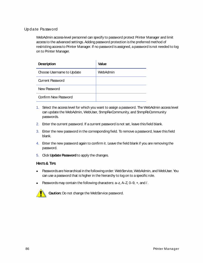
Update Password
WebAdmin access-level personnel can specify to password protect Printer Manager and limit
access to the advanced settings. Adding password protection is the preferred method of
restricting access to Printer Manager. If no password is assigned, a password is not needed to log
on to Printer Manager.
1. Select the access level for which you want to assign a password. The WebAdmin access level
can update the WebAdmin, WebUser, SnmpRwCommunity, and SnmpRoCommunity
passwords.
2. Enter the current password. If a current password is not set, leave this field blank.
3. Enter the new password in the corresponding field. To remove a password, leave this field
blank.
4. Enter the new password again to confirm it. Leave the field blank if you are removing the
password.
5. Click Update Password to apply the changes.
HINTS & TIPS
Passwords are hierarchical in the following order: WebService, WebAdmin, and WebUser. You
can use a password that is higher in the hierarchy to log on to a specific role.
Passwords may contain the following characters: a–z, A–Z, 0–9, +, and /.
Description Value
Choose Username to Update WebAdmin
Current Password
New Password
Confirm New Password
Caution: Do not change the WebService password.
86 Printer Manager
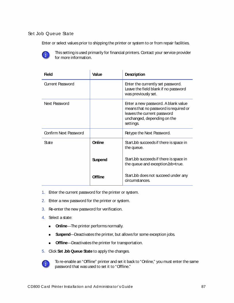
Set Job Queue State
Enter or select values prior to shipping the printer or system to or from repair facilities.
1. Enter the current password for the printer or system.
2. Enter a new password for the printer or system.
3. Re-enter the new password for verification.
4. Select a state:
Online—The printer performs normally.
Suspend—Deactivates the printer, but allows for some exception jobs.
Offline—Deactivates the printer for transportation.
5. Click Set Job Queue State to apply the changes.
This setting is used primarily for financial printers. Contact your service provider for more information.
Field Value Description
Current Password Enter the currently set password. Leave the field blank if no password was previously set.
Next Password Enter a new password. A blank value means that no password is required or leaves the current password unchanged, depending on the settings.
Confirm Next Password Retype the Next Password.
State Online
Suspend
Offline
StartJob succeeds if there is space in the queue.
StartJob succeeds if there is space in the queue and exceptionJob=true.
StartJob does not succeed under any circumstances.
To re-enable an “Offline” printer and set it back to “Online,” you must enter the same password that was used to set it to “Offline.”
CD800 Card Printer Installation and Administrator’s Guide 87
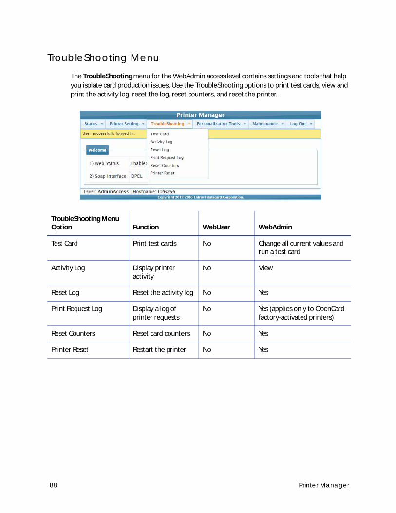
TroubleShooting MenuThe TroubleShooting menu for the WebAdmin access level contains settings and tools that help
you isolate card production issues. Use the TroubleShooting options to print test cards, view and
print the activity log, reset the log, reset counters, and reset the printer.
TroubleShooting Menu Option Function WebUser WebAdmin
Test Card Print test cards No Change all current values and run a test card
Activity Log Display printer activity
No View
Reset Log Reset the activity log No Yes
Print Request Log Display a log of printer requests
No Yes (applies only to OpenCard factory-activated printers)
Reset Counters Reset card counters No Yes
Printer Reset Restart the printer No Yes
88 Printer Manager
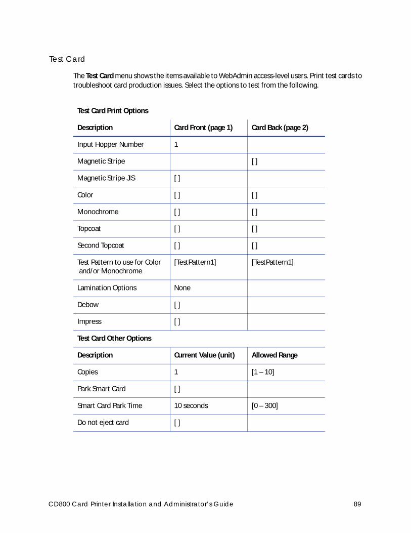
Test Card
The Test Card menu shows the items available to WebAdmin access-level users. Print test cards to
troubleshoot card production issues. Select the options to test from the following.
Test Card Print Options
Description Card Front (page 1) Card Back (page 2)
Input Hopper Number 1
Magnetic Stripe [ ]
Magnetic Stripe JIS [ ]
Color [ ] [ ]
Monochrome [ ] [ ]
Topcoat [ ] [ ]
Second Topcoat [ ] [ ]
Test Pattern to use for Color and/or Monochrome
[TestPattern1] [TestPattern1]
Lamination Options None
Debow [ ]
Impress [ ]
Test Card Other Options
Description Current Value (unit) Allowed Range
Copies 1 [1 – 10]
Park Smart Card [ ]
Smart Card Park Time 10 seconds [0 – 300]
Do not eject card [ ]
CD800 Card Printer Installation and Administrator’s Guide 89
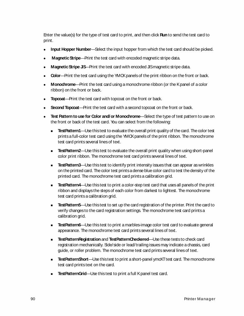
Enter the value(s) for the type of test card to print, and then click Run to send the test card to
print.
Input Hopper Number—Select the input hopper from which the test card should be picked.
Magnetic Stripe—Print the test card with encoded magnetic stripe data.
Magnetic Stripe JIS—Print the test card with encoded JIS magnetic stripe data.
Color—Print the test card using the YMCK panels of the print ribbon on the front or back.
Monochrome—Print the test card using a monochrome ribbon (or the K panel of a color
ribbon) on the front or back.
Topcoat—Print the test card with topcoat on the front or back.
Second Topcoat—Print the test card with a second topcoat on the front or back.
Test Pattern to use for Color and/or Monochrome—Select the type of test pattern to use on
the front or back of the test card. You can select from the following:
TestPattern1—Use this test to evaluate the overall print quality of the card. The color test
prints a full-color test card using the YMCK panels of the print ribbon. The monochrome
test card prints several lines of text.
TestPattern2—Use this test to evaluate the overall print quality when using short-panel
color print ribbon. The monochrome test card prints several lines of text.
TestPattern3—Use this test to identify print intensity issues that can appear as wrinkles
on the printed card. The color test prints a dense blue color card to test the density of the
printed card. The monochrome test card prints a calibration grid.
TestPattern4—Use this test to print a color-step test card that uses all panels of the print
ribbon and displays the steps of each color from darkest to lightest. The monochrome
test card prints a calibration grid.
TestPattern5—Use this test to set up the card registration of the printer. Print the card to
verify changes to the card registration settings. The monochrome test card prints a
calibration grid.
TestPattern6—Use this test to print a marbles-image color test card to evaluate general
appearance. The monochrome test card prints several lines of text.
TestPatternRegistration and TestPatternCheckered—Use these tests to check card
registration mechanically. Side/side or lead/trailing issues may indicate a chassis, card
guide, or roller problem. The monochrome test card prints several lines of text.
TestPatternShort—Use this test to print a short-panel ymcKT test card. The monochrome
test card prints text on the card.
TestPatternGrid—Use this test to print a full K panel test card.
90 Printer Manager
TestPatternPaleBlue—Use this test to identify print intensity issues that can appear as
wrinkles on the printed card. This option prints a lighter blue color card than
TestPattern3. The monochrome test card prints several lines of Katakana text on the card.
TestPatternManufacture A–E—These test cards are used only during manufacturing
setup.
Lamination Options—Use this test to determine whether a laminator system is applying
overlay material properly. You can select from the following lamination options:
L1 Front—Applies overlay from the L1 laminator to the front of the card.
L1 Back—Applies overlay from the L1 laminator to the back of the card.
L1 Front L1 Back—Applies overlay from the L1 laminator to the front and back of the
card.
L2 Front—Applies overlay from the L2 laminator to the front of the card.
L2 Back—Applies overlay from the L2 laminator to the back of the card.
L2 Front L2 Back—Applies overlay from the L2 laminator to the front and back of the
card.
L2 Back L1 Front—Applies overlay from the L2 laminator to the back of the card, and
overlay from the L1 laminator to the front of the card.
L2 Front L1 Back—Applies overlay from the L2 laminator to the front of the card, and
overlay from the L1 laminator to the back of the card.
Debow—Select this option to apply the debow action when an overlay is applied to the card.
Impress—Select this option to impress a card, if an impresser is installed.
Copies—Enter the number of test cards to print for each test, from 1 to 10.
Park Smart Card—Select this option to park the test card in the smart card bay. The test does
not transmit any data, but is used to test the movement of the card into, and out of, the bay.
Smart Card Park Time—Enter the amount of time to hold the test card in the smart card bay,
from 0 to 300 seconds.
Do not eject card—Select this option to prevent the test card from being ejected from the
printer.
CD800 Card Printer Installation and Administrator’s Guide 91
Activity Log
The Activity Log displays information about printer activity. It includes all actions and errors since
last reset. Save and send the activity log to your service provider when you request service. The
log provides valuable information for troubleshooting printer performance issues.
1. Click Download to save the activity log information.
2. Enter a location on your PC to save the file.
3. Save and send the activity log to your service provider when you request service.
Sample Data
12: 0d 00h 00m 25.202s [SYSTEM__CRIT ] value of flip det <1> value of opt board det <1>
value of punch det <0> in printer.cpp
14: 0d 00h 00m 25.196s [SYSTEM__WARNING] Improper shutdown detected
14: 0d 01h 10m 14.135s [JOB_____NOTICE ] Resolved condition 1-JobFailed Notice 637/638
"hostname".770962.0.0
Reset Log
The Reset Log option allows a WebAdmin access-level user to reset the Activity Log.
Click Run to reset the Activity Log.
Print Request Log
The Print Request Log option allows a WebAdmin access-level user to view and reset the Print
Request Log.
Select the Number of Logs (5, 10, 15, 20, 25, or All) and click Run to view a log of the print
requests sent to the printer.
To reset the audit log, click Run in the Reset Log field.
Reset Counters
The Reset Counters option resets the Current Card counter functions in the printer. Life counters
or total card counts cannot be reset.
Click Run to reset the counters.
Printer Reset
The Printer Reset option restarts the printer.
Click Run to restart the printer.
This option applies only to OpenCard factory-activated printers.
92 Printer Manager
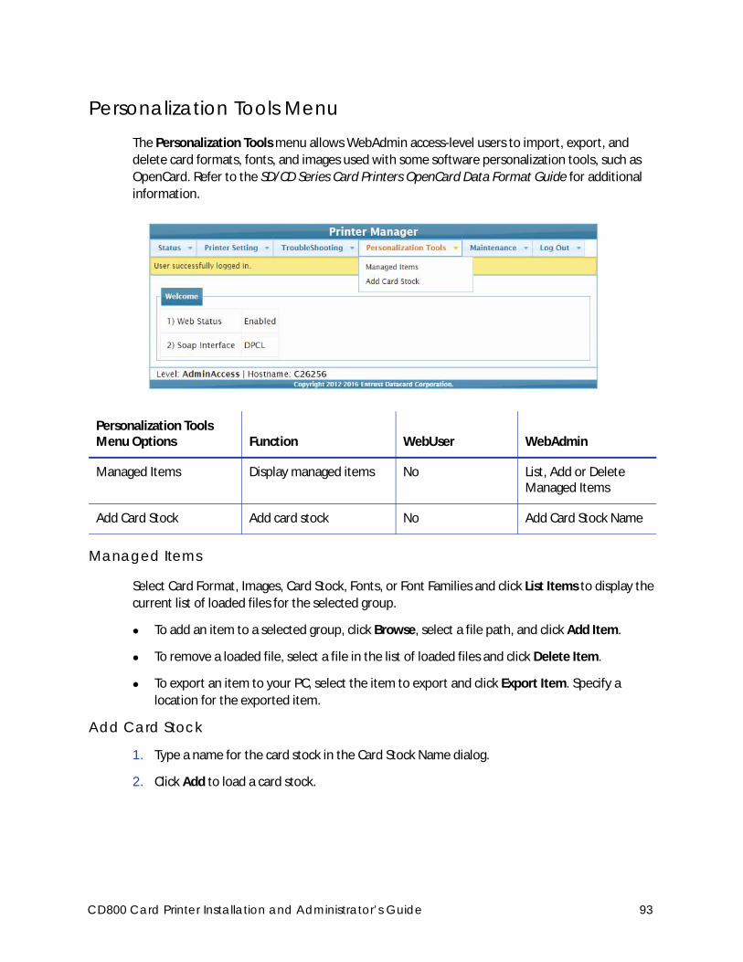
Personalization Tools MenuThe Personalization Tools menu allows WebAdmin access-level users to import, export, and
delete card formats, fonts, and images used with some software personalization tools, such as
OpenCard. Refer to the SD/CD Series Card Printers OpenCard Data Format Guide for additional
information.
Managed Items
Select Card Format, Images, Card Stock, Fonts, or Font Families and click List Items to display the
current list of loaded files for the selected group.
To add an item to a selected group, click Browse, select a file path, and click Add Item.
To remove a loaded file, select a file in the list of loaded files and click Delete Item.
To export an item to your PC, select the item to export and click Export Item. Specify a
location for the exported item.
Add Card Stock
1. Type a name for the card stock in the Card Stock Name dialog.
2. Click Add to load a card stock.
Personalization Tools Menu Options Function WebUser WebAdmin
Managed Items Display managed items No List, Add or Delete Managed Items
Add Card Stock Add card stock No Add Card Stock Name
CD800 Card Printer Installation and Administrator’s Guide 93
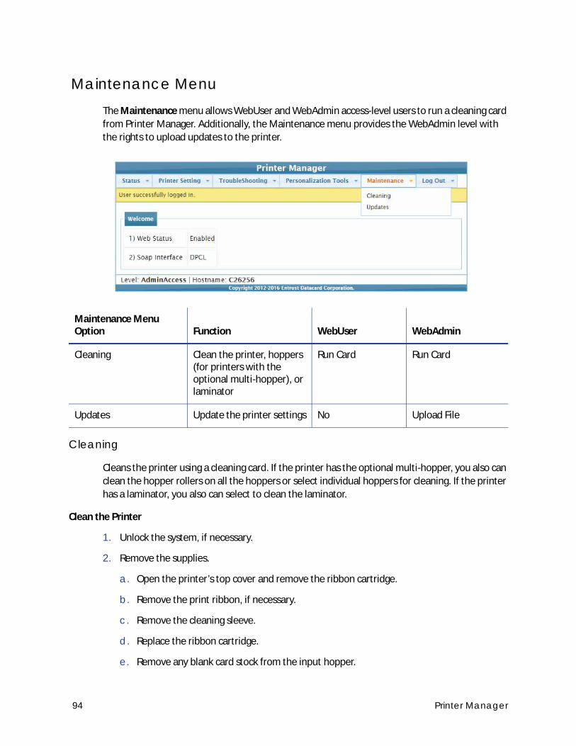
Maintenance MenuThe Maintenance menu allows WebUser and WebAdmin access-level users to run a cleaning card
from Printer Manager. Additionally, the Maintenance menu provides the WebAdmin level with
the rights to upload updates to the printer.
Cleaning
Cleans the printer using a cleaning card. If the printer has the optional multi-hopper, you also can
clean the hopper rollers on all the hoppers or select individual hoppers for cleaning. If the printer
has a laminator, you also can select to clean the laminator.
Clean the Printer
1. Unlock the system, if necessary.
2. Remove the supplies.
a. Open the printer’s top cover and remove the ribbon cartridge.
b. Remove the print ribbon, if necessary.
c. Remove the cleaning sleeve.
d. Replace the ribbon cartridge.
e. Remove any blank card stock from the input hopper.
Maintenance Menu Option Function WebUser WebAdmin
Cleaning Clean the printer, hoppers (for printers with the optional multi-hopper), or laminator
Run Card Run Card
Updates Update the printer settings No Upload File
94 Printer Manager
f. Close the printer cover.
g. Lock the printer.
3. Place the unwrapped cleaning card in the card input hopper. If your printer has the optional
multi-hopper, place the cleaning card in hopper 2.
4. Select Maintenance > Cleaning.
5. Select Clean Printer.
6. Click Run to start the cleaning process. Press the USER button on the printer when the
message “172: Insert cleaning card” displays on the LCD panel.
The printer picks the cleaning card, moves it through the printer several times, and ejects it in
the output hopper or card reject tray.
7. Remove the used cleaning card. Wait a few minutes for the rollers to dry.
8. Replace the supplies.
a. Place the cards in the input hopper.
b. Replace the print ribbon, if necessary.
c. Replace the cleaning sleeve with a new sleeve and remove the protective cover.
d. Replace the ribbon cartridge and close the printer cover. Lock the printer, if necessary.
Clean the Multi-Hopper
1. Unlock the printer and open the multi-hopper cover.
2. Remove any blank card stock from the hoppers.
3. Open the cleaning card package and insert the cleaning cards into the hoppers you plan to
clean.
4. Close the multi-hopper cover.
5. Select either Clean All Hoppers or Clean Hopper and select the number of the hopper you
want to clean.
6. Click Run to start the cleaning process. Press the USER button on the printer when the
message “172: Insert cleaning card” displays on the LCD panel.
The cleaning cards are moved back and forth across the hopper rollers several times and then
ejected back into the hoppers.
7. Open the multi-hopper door and remove the cleaning cards.
8. Replace the card stock in the hoppers and lock the printer.
CD800 Card Printer Installation and Administrator’s Guide 95
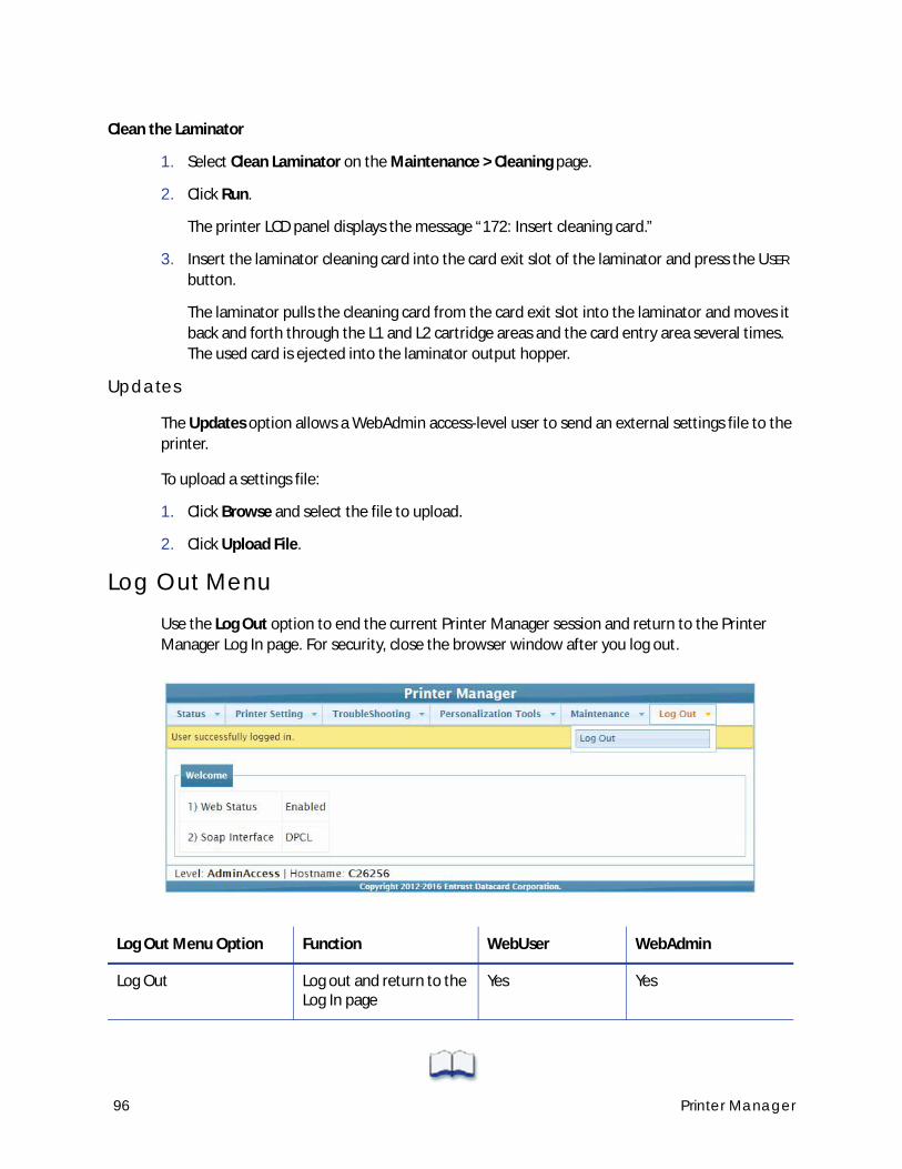
96 Printer Manager
Clean the Laminator
1. Select Clean Laminator on the Maintenance > Cleaning page.
2. Click Run.
The printer LCD panel displays the message “172: Insert cleaning card.”
3. Insert the laminator cleaning card into the card exit slot of the laminator and press the USER
button.
The laminator pulls the cleaning card from the card exit slot into the laminator and moves it
back and forth through the L1 and L2 cartridge areas and the card entry area several times.
The used card is ejected into the laminator output hopper.
Updates
The Updates option allows a WebAdmin access-level user to send an external settings file to the
printer.
To upload a settings file:
1. Click Browse and select the file to upload.
2. Click Upload File.
Log Out MenuUse the Log Out option to end the current Printer Manager session and return to the Printer
Manager Log In page. For security, close the browser window after you log out.
Log Out Menu Option Function WebUser WebAdmin
Log Out Log out and return to the Log In page
Yes Yes
Chapter 4: Supplies and Parts
This section describes the supplies and parts for the printer. It includes:
Print Ribbon on page 98
Laminator Supplies on page 102
Cards on page 105
Cleaning Supplies on page 107
Replacement Parts on page 108
Optional Equipment on page 109
Cables and Power Supplies on page 110
CD800 Card Printer Installation and Administrator’s Guide 97
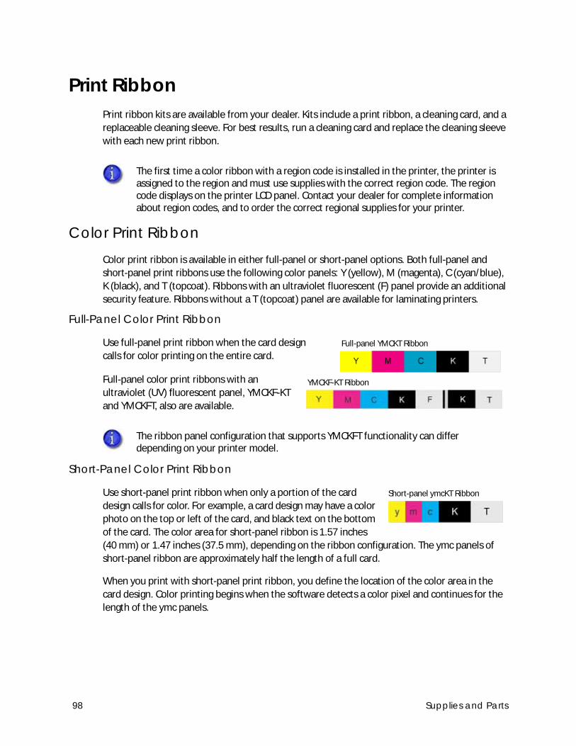
Print RibbonPrint ribbon kits are available from your dealer. Kits include a print ribbon, a cleaning card, and a
replaceable cleaning sleeve. For best results, run a cleaning card and replace the cleaning sleeve
with each new print ribbon.
Color Print RibbonColor print ribbon is available in either full-panel or short-panel options. Both full-panel and
short-panel print ribbons use the following color panels: Y (yellow), M (magenta), C (cyan/blue),
K (black), and T (topcoat). Ribbons with an ultraviolet fluorescent (F) panel provide an additional
security feature. Ribbons without a T (topcoat) panel are available for laminating printers.
Full-Panel Color Print Ribbon
Use full-panel print ribbon when the card design
calls for color printing on the entire card.
Full-panel color print ribbons with an
ultraviolet (UV) fluorescent panel, YMCKF-KT
and YMCKFT, also are available.
Short-Panel Color Print Ribbon
Use short-panel print ribbon when only a portion of the card
design calls for color. For example, a card design may have a color
photo on the top or left of the card, and black text on the bottom
of the card. The color area for short-panel ribbon is 1.57 inches
(40 mm) or 1.47 inches (37.5 mm), depending on the ribbon configuration. The ymc panels of
short-panel ribbon are approximately half the length of a full card.
When you print with short-panel print ribbon, you define the location of the color area in the
card design. Color printing begins when the software detects a color pixel and continues for the
length of the ymc panels.
The first time a color ribbon with a region code is installed in the printer, the printer is assigned to the region and must use supplies with the correct region code. The region code displays on the printer LCD panel. Contact your dealer for complete information about region codes, and to order the correct regional supplies for your printer.
The ribbon panel configuration that supports YMCKFT functionality can differ depending on your printer model.
Full-panel YMCKT Ribbon
YMCKF-KT Ribbon
Short-panel ymcKT Ribbon
98 Supplies and Parts
Color Print Ribbon Kits
The following color print ribbon kits are available.
YMCKT Color Ribbon, 250 images per roll
YMCKT Color Ribbon, 500 images per roll
ymcKT (short-panel) Color Ribbon, 650 images per roll
YMCKT-K Color Ribbon, 375 images per roll
YMCKT-KT Color Ribbon, 300 images per roll
ymcKT-KT (short panel) Color Ribbon, 435 images per roll
YMCKFT Color Ribbon with UV, 300 images per roll
YMCK Color Ribbon, 500 images per roll (laminating systems only)
YMCK-K Color Ribbon, 500 images per roll (laminating systems only)
YMCKF-KT Color Ribbon with UV, 300 images per roll (laminating systems only)
Monochrome Print RibbonA monochrome ribbon prints the entire card in one color.
Monochrome ribbon can be:
Alternating black and topcoat panels (KT or KTT ribbon)
Continuous black (K ribbon)
A continuous color, such as red or silver
Silver with Topcoat, Black with Topcoat (ST-KT)
Gold with Topcoat, Black with Topcoat (GT-KT)
Some of the ribbons in the following list do not have a region code and can be used in any printer. Contact your dealer for more information and to order supplies.
Monochrome ribbons do not have a region code and can be used by all printers.
CD800 Card Printer Installation and Administrator’s Guide 99
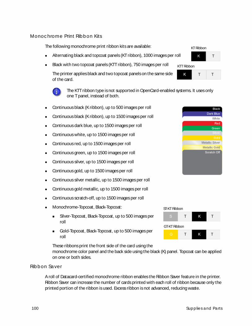
Monochrome Print Ribbon Kits
The following monochrome print ribbon kits are available:
Alternating black and topcoat panels (KT ribbon), 1000 images per roll
Black with two topcoat panels (KTT ribbon), 750 images per roll
The printer applies black and two topcoat panels on the same side
of the card.
Continuous black (K ribbon), up to 500 images per roll
Continuous black (K ribbon), up to 1500 images per roll
Continuous dark blue, up to 1500 images per roll
Continuous white, up to 1500 images per roll
Continuous red, up to 1500 images per roll
Continuous green, up to 1500 images per roll
Continuous silver, up to 1500 images per roll
Continuous gold, up to 1500 images per roll
Continuous silver metallic, up to 1500 images per roll
Continuous gold metallic, up to 1500 images per roll
Continuous scratch-off, up to 1500 images per roll
Monochrome-Topcoat, Black-Topcoat:
Silver-Topcoat, Black-Topcoat, up to 500 images per
roll
Gold-Topcoat, Black-Topcoat, up to 500 images per
roll
These ribbons print the front side of the card using the
monochrome color panel and the back side using the black (K) panel. Topcoat can be applied
on one or both sides.
Ribbon Saver
A roll of Datacard-certified monochrome ribbon enables the Ribbon Saver feature in the printer.
Ribbon Saver can increase the number of cards printed with each roll of ribbon because only the
printed portion of the ribbon is used. Excess ribbon is not advanced, reducing waste.
The KTT ribbon type is not supported in OpenCard-enabled systems. It uses only one T panel, instead of both.
KT Ribbon
KTT Ribbon
ST-KT Ribbon
GT-KT Ribbon
100 Supplies and Parts

Print Ribbon Storage Guidelines Store print ribbon in the original package until you load it in the printer. Keep the original
packaging closed until you are ready to use the ribbon.
The print ribbon maintains its quality for about one year. For optimum card quality, purchase
and store quantities of print ribbon that can be used within one year.
The print ribbon and card stock might require secure storage and tracking. Follow your
organization’s policy for storing and tracking the supplies used to make cards.
Store the print ribbon in a location away from direct sunlight, with a temperature between
32° and 77°F (0° and 25°C). A range of 40% to 60% non-condensing humidity is
recommended.
Install supply rolls at room temperature. If supplies are stored in an environment that is
cooler than the printer environment, allow supplies to reach room temperature before you
use them.
If the printer will not be used for an extended period, remove supplies from the printer and
store them with new supplies.
CD800 Card Printer Installation and Administrator’s Guide 101

Laminator SuppliesThe laminator applies topcoat or patch overlay material to the front and back of the card. Topcoat
is a continuous film and patch is a die-cut polyester shape designed to fit standard ISO ID-1 size
card stock.
Topcoat and Patch OverlaysA patch overlay can cover the complete card, can have a opening for a smart card chip, or can
cover the card under the magnetic stripe.
Both topcoat and patch overlays can be clear or can have a transparent holographic image on
them. The holographic materials are called holographic topcoat or holographic patch and also
can be ordered with a custom image. In addition, holographic topcoat or patch can be designed
with a registered image that is located in the same position on each card.
Complete Card Smart Card Magnetic Stripe
Clear Topcoat Clear Patch
Random Holographic PatchRandom Holographic Topcoat
Registered Holographic Topcoat Registered Holographic Patch
102 Supplies and Parts
The following laminator supplies are available. Most are available for a full card, smart card, or
magnetic stripe card.
Patch:
Clear DuraGard®, 0.5 mil, up to 350 images/roll
Clear DuraGard, 1.0 mil, up to 300 images/roll
Holographic DuraGard 0.6 mil, Random, up to 350 images/roll
Holographic DuraGard, Registered, 0.6 mil, up to 350 images/roll
Holographic DuraGard, 1.0 mil, Random, up to 300 images/roll
Holographic DuraGard Registered, 1.0 mil, up to 300 images/roll
Holographic DuraGard, Registered, Serialized, 1.0 mil, up to 300 images/roll
Topcoat:
Clear, number of images depends on lamination settings
Holographic, Random, number of images depends on lamination settings
Registered Holographic, up to 600 images/roll
Clear DuraShield™, number of images depends on lamination settings (see note)
Holographic DuraShield, Random, number of images depends on lamination settings (see
note)
Holographic DuraShield, Registered, 500 images/roll (see note)
Caution: DuraGard patch overlay cannot be applied over a “T” panel topcoat applied from a ribbon. Make sure that the DuraGard patch is applied to the card side without a “T” panel topcoat.
DuraShield clear and holographic overlays must be used with a ribbon that includes an inline topcoat (T) panel, for example, KT, YMCKT, YMCKT-K, YMCKT-KT, ymcKT, or YMCKF-KT. It must be applied over the topcoat.
CD800 Card Printer Installation and Administrator’s Guide 103

Overlay Storage Guidelines Store overlay material in the original package until you load it in the laminator. Keep the
original packaging closed until you are ready to use the overlay.
The overlay maintains its quality for about one year. For optimum card quality, purchase and
store quantities of material that can be used within one year.
Overlay material might require secure storage and tracking. Follow your organization’s policy
for storing and tracking the supplies used to make cards.
Store the overlay in a location away from direct sunlight, with a temperature between 50°
and 80°F (10° and 27°C). A range of 30% to 70% humidity is recommended.
Install supply rolls at room temperature. If supplies are stored in an environment that is
cooler than the printer environment, allow supplies to reach room temperature before you
use them.
If the printer will not be used for an extended period, remove supplies from the printer and
store them with new supplies.
104 Supplies and Parts
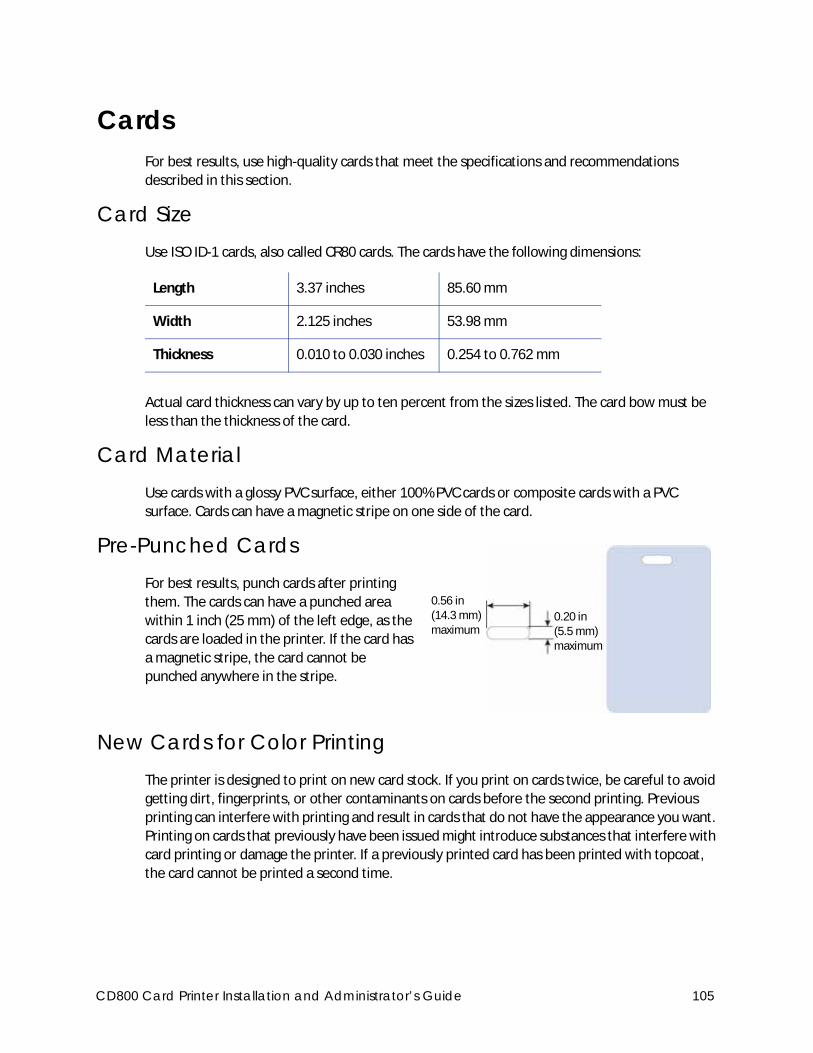
CardsFor best results, use high-quality cards that meet the specifications and recommendations
described in this section.
Card SizeUse ISO ID-1 cards, also called CR80 cards. The cards have the following dimensions:
Actual card thickness can vary by up to ten percent from the sizes listed. The card bow must be
less than the thickness of the card.
Card MaterialUse cards with a glossy PVC surface, either 100% PVC cards or composite cards with a PVC
surface. Cards can have a magnetic stripe on one side of the card.
Pre-Punched Cards For best results, punch cards after printing
them. The cards can have a punched area
within 1 inch (25 mm) of the left edge, as the
cards are loaded in the printer. If the card has
a magnetic stripe, the card cannot be
punched anywhere in the stripe.
New Cards for Color PrintingThe printer is designed to print on new card stock. If you print on cards twice, be careful to avoid
getting dirt, fingerprints, or other contaminants on cards before the second printing. Previous
printing can interfere with printing and result in cards that do not have the appearance you want.
Printing on cards that previously have been issued might introduce substances that interfere with
card printing or damage the printer. If a previously printed card has been printed with topcoat,
the card cannot be printed a second time.
Length 3.37 inches 85.60 mm
Width 2.125 inches 53.98 mm
Thickness 0.010 to 0.030 inches 0.254 to 0.762 mm
0.20 in (5.5 mm) maximum
0.56 in(14.3 mm)maximum
CD800 Card Printer Installation and Administrator’s Guide 105
Adhesive-Backed CardsAdhesive-backed cards are printed, and then adhered to contactless smart cards when the card
surface is not flat enough to print. Use only Datacard adhesive-backed cards with the printer. The
printing surface (white side) of an adhesive-backed card meets the material requirements for use
in the printer. Use the following guidelines:
Store cards in a cool place (such as a refrigerator) to avoid adhesive migration.
Clean the printer’s card tracks to remove any adhesive residue. Use a printhead cleaning
swab or isopropanol and a swab to remove the residue.
Use a print margin of at least 0.05 inch when using adhesive-backed cards.
Do not apply laminator overlay material to adhesive-backed cards.
Card Quality GuidelinesCards must meet the following card quality guidelines for the printer to print high-quality
graphics on them successfully.
Card Surface
The card must be smooth and even, and free of irregularities such as raised burrs or particles
embedded in the surface. Surface irregularities can cause printing voids, especially when printing
edge to edge.
Card Handling
These guidelines apply to unprinted cards.
Any debris or particles on the surface of an unprinted card can reduce print quality and
damage the printhead.
Grease or oils, such as oils from your fingers, also reduce print quality. Keep cards completely
clean. Do not touch the print surface of a card with your fingers or hands. Handle blank card
stock by the edges only or wear gloves.
Do not use a rubber band to bind blank cards together.
If you drop a card on the floor, do not insert it into the printer.
106 Supplies and Parts
Card Storage
These guidelines apply to both printed and unprinted cards.
Cards must be stacked so that they do not shift and rub against each other.
When you store cards, make sure that no two cards contain images or blocks of color that
come in contact with each other.
Make sure that the magnetic stripe on one card does not come in contact with the magnetic
stripe on another card.
Make sure that cards with magnetic stripes are stored away from magnets and other
magnetic objects.
Store cards in a cool, dry, and dark place. Excessive light can cause yellowing of cards on
exposed edges.
Keep cards in their original packaging.
Cards must be at room temperature when they are used. If cards are stored in a cooler
environment than the printer, allow them to reach room temperature before you use them.
Cleaning SuppliesThe print ribbon kit includes a cleaning card and a replaceable cleaning sleeve. For best results,
keep additional cleaning supplies on hand.
The following additional cleaning supplies are available:
Supply Description
Printer cleaning cards Pack of 10 double-sided, isopropanol-coated cleaning cards used to clean the printer card track and transport rollers.
Cleaning sleeves Pack of 5 replaceable, adhesive-coated cleaning sleeves.
Cleaning swabs Pack of 5 isopropanol-saturated cleaning swabs to clean debris and dust from the printhead and from hard-to-reach internal areas of the printer.
Laminator cleaning cards Pack of 10 double-sided, sticky cleaning cards used to clean the laminator when a holographic overlay is installed.
CD800 Card Printer Installation and Administrator’s Guide 107
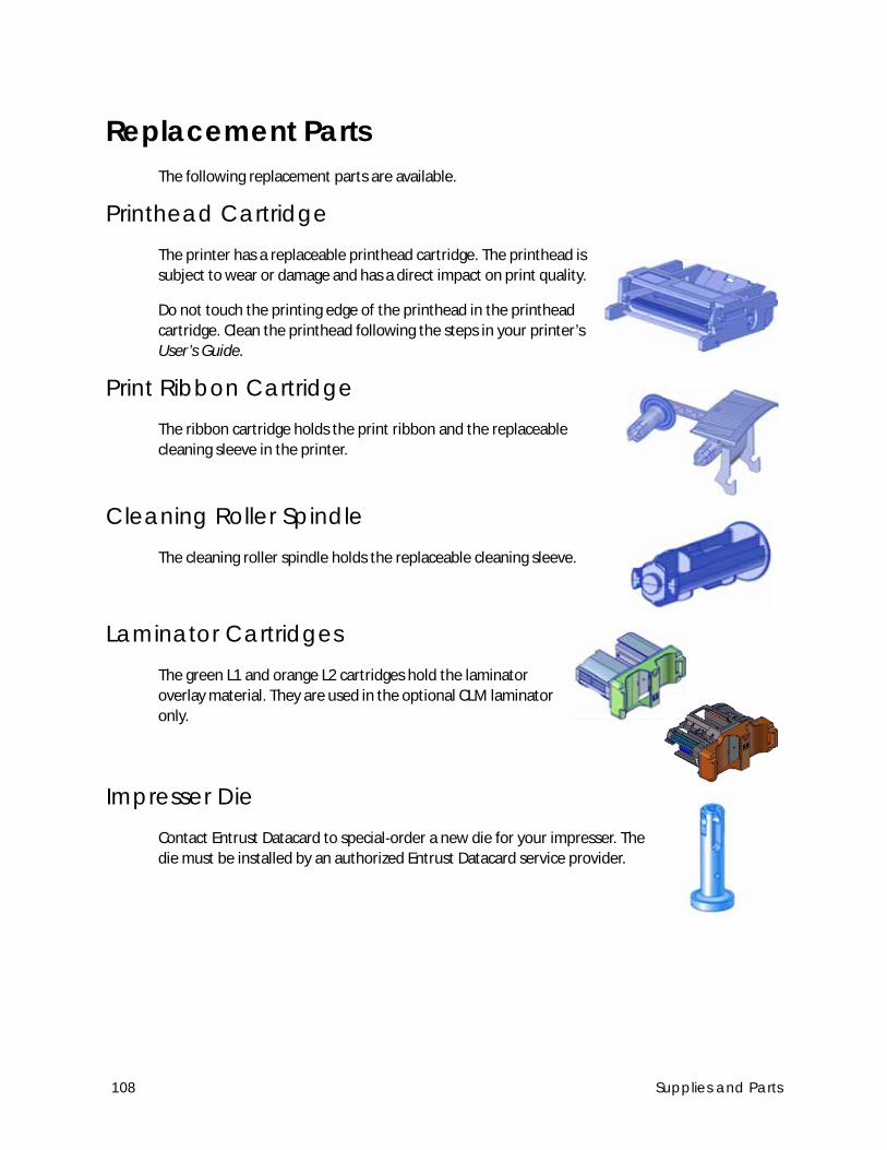
Replacement PartsThe following replacement parts are available.
Printhead CartridgeThe printer has a replaceable printhead cartridge. The printhead is
subject to wear or damage and has a direct impact on print quality.
Do not touch the printing edge of the printhead in the printhead
cartridge. Clean the printhead following the steps in your printer’s
User’s Guide.
Print Ribbon Cartridge The ribbon cartridge holds the print ribbon and the replaceable
cleaning sleeve in the printer.
Cleaning Roller Spindle The cleaning roller spindle holds the replaceable cleaning sleeve.
Laminator Cartridges The green L1 and orange L2 cartridges hold the laminator
overlay material. They are used in the optional CLM laminator
only.
Impresser Die Contact Entrust Datacard to special-order a new die for your impresser. The
die must be installed by an authorized Entrust Datacard service provider.
108 Supplies and Parts
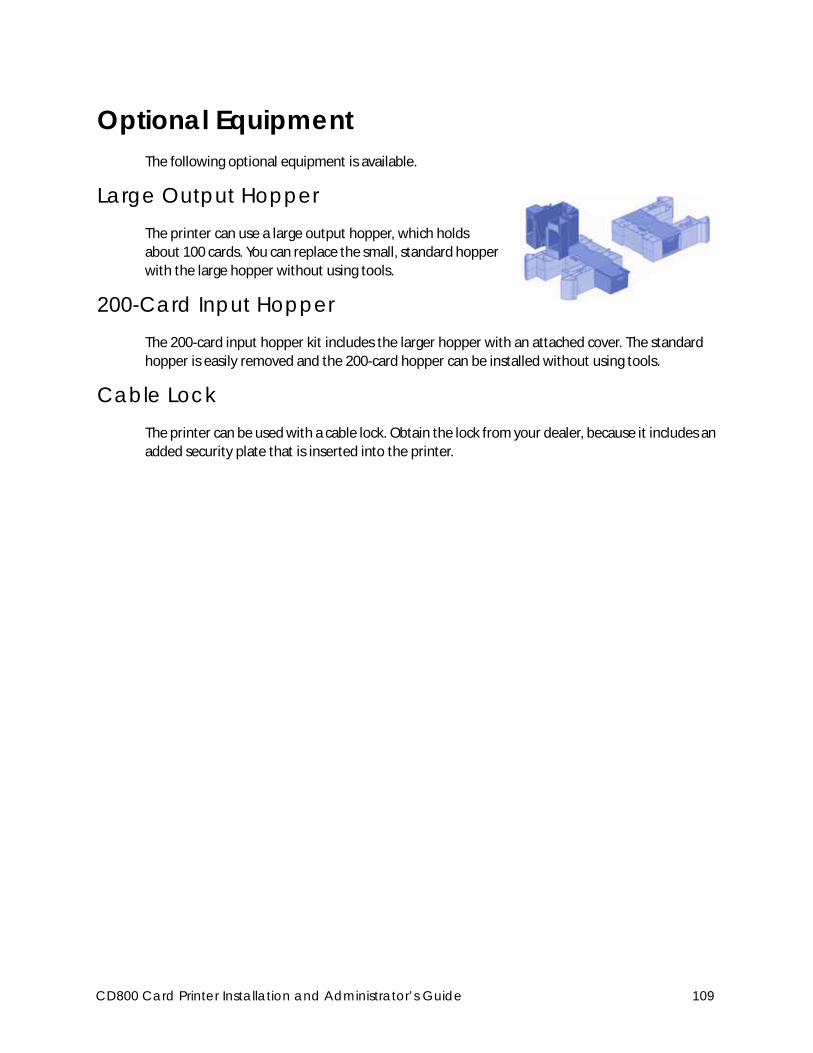
Optional EquipmentThe following optional equipment is available.
Large Output Hopper The printer can use a large output hopper, which holds
about 100 cards. You can replace the small, standard hopper
with the large hopper without using tools.
200-Card Input HopperThe 200-card input hopper kit includes the larger hopper with an attached cover. The standard
hopper is easily removed and the 200-card hopper can be installed without using tools.
Cable LockThe printer can be used with a cable lock. Obtain the lock from your dealer, because it includes an
added security plate that is inserted into the printer.
CD800 Card Printer Installation and Administrator’s Guide 109
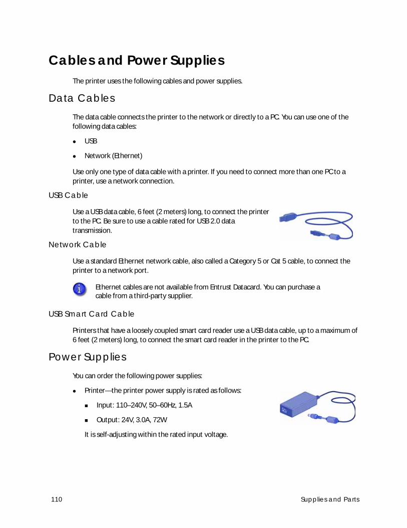
Cables and Power SuppliesThe printer uses the following cables and power supplies.
Data CablesThe data cable connects the printer to the network or directly to a PC. You can use one of the
following data cables:
USB
Network (Ethernet)
Use only one type of data cable with a printer. If you need to connect more than one PC to a
printer, use a network connection.
USB Cable
Use a USB data cable, 6 feet (2 meters) long, to connect the printer
to the PC. Be sure to use a cable rated for USB 2.0 data
transmission.
Network Cable
Use a standard Ethernet network cable, also called a Category 5 or Cat 5 cable, to connect the
printer to a network port.
USB Smart Card Cable
Printers that have a loosely coupled smart card reader use a USB data cable, up to a maximum of
6 feet (2 meters) long, to connect the smart card reader in the printer to the PC.
Power SuppliesYou can order the following power supplies:
Printer—the printer power supply is rated as follows:
Input: 110–240V, 50–60Hz, 1.5A
Output: 24V, 3.0A, 72W
It is self-adjusting within the rated input voltage.
Ethernet cables are not available from Entrust Datacard. You can purchase a cable from a third-party supplier.
110 Supplies and Parts

Laminator–the laminator power supplies are rated as follows:
Laminator with L1 only:
Input: 100–240V, 47–63Hz, 2.2A
Output: 24V, 3.75A, 90W
Laminator with L1 and L2:
Input: 100–240V, 47–63Hz, 2.2A
Output: 24V, 6.6A, 160W
Laminator power supplies are self-adjusting within the rated input voltage
Power CordsYou can order power cords for the following:
Printer—The printer power cord connects the printer power supply to the facility power. Be
sure to use a cord that grounds to the facility power source.
Laminator—The laminator power cord connects the laminator power supply to the facility
power.
The printer and laminator can use one of the following country-
specific power cords:
USA power cord
Australia power cord
Brazil power cord
China power cord
Denmark power cord
European power cord
India power cord
Israel power cord
Italy power cord
Japan power cord
South Africa power cord
Swiss power cord
United Kingdom power cord
CD800 Card Printer Installation and Administrator’s Guide 111

112 Supplies and Parts
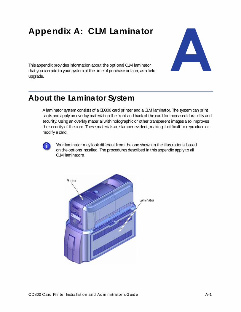
Appendix A: CLM Laminator
This appendix provides information about the optional CLM laminator
that you can add to your system at the time of purchase or later, as a field
upgrade.
About the Laminator SystemA laminator system consists of a CD800 card printer and a CLM laminator. The system can print
cards and apply an overlay material on the front and back of the card for increased durability and
security. Using an overlay material with holographic or other transparent images also improves
the security of the card. These materials are tamper evident, making it difficult to reproduce or
modify a card.
Your laminator may look different from the one shown in the illustrations, based on the options installed. The procedures described in this appendix apply to all CLM laminators.
Laminator
Printer
CD800 Card Printer Instrallation and Administrator’s Guide A-1
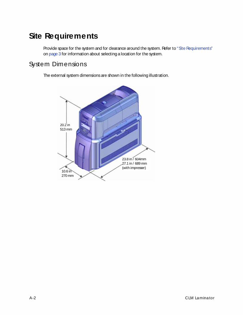
Site RequirementsProvide space for the system and for clearance around the system. Refer to “Site Requirements”
on page 3 for information about selecting a location for the system.
System DimensionsThe external system dimensions are shown in the following illustration.
10.6 in270 mm
20.2 in513 mm
23.8 in / 604mm27.1 in / 689 mm (with impresser)
A-2 CLM Laminator
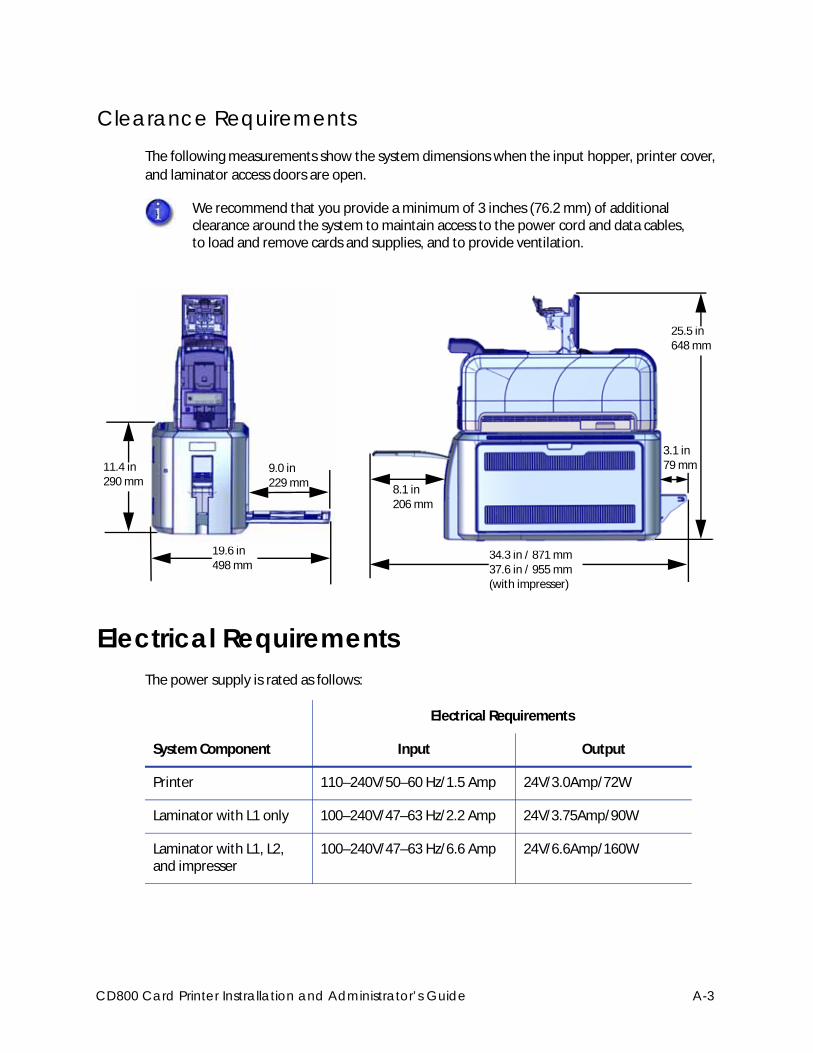
Clearance RequirementsThe following measurements show the system dimensions when the input hopper, printer cover,
and laminator access doors are open.
Electrical RequirementsThe power supply is rated as follows:
We recommend that you provide a minimum of 3 inches (76.2 mm) of additional clearance around the system to maintain access to the power cord and data cables, to load and remove cards and supplies, and to provide ventilation.
System Component
Electrical Requirements
Input Output
Printer 110–240V/50–60 Hz/1.5 Amp 24V/3.0Amp/72W
Laminator with L1 only 100–240V/47–63 Hz/2.2 Amp 24V/3.75Amp/90W
Laminator with L1, L2, and impresser
100–240V/47–63 Hz/6.6 Amp 24V/6.6Amp/160W
19.6 in498 mm
9.0 in229 mm
11.4 in290 mm
34.3 in / 871 mm37.6 in / 955 mm(with impresser)
8.1 in206 mm
25.5 in648 mm
3.1 in79 mm
CD800 Card Printer Instrallation and Administrator’s Guide A-3
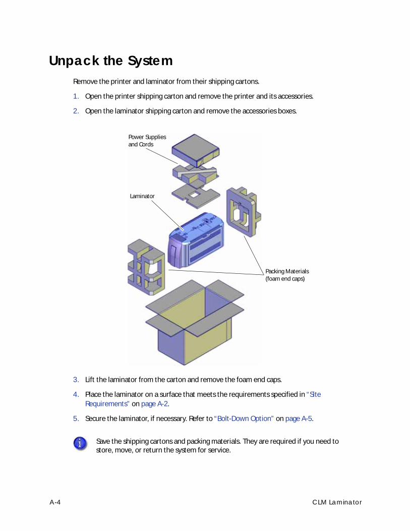
Unpack the SystemRemove the printer and laminator from their shipping cartons.
1. Open the printer shipping carton and remove the printer and its accessories.
2. Open the laminator shipping carton and remove the accessories boxes.
3. Lift the laminator from the carton and remove the foam end caps.
4. Place the laminator on a surface that meets the requirements specified in “Site
Requirements” on page A-2.
5. Secure the laminator, if necessary. Refer to “Bolt-Down Option” on page A-5.
Save the shipping cartons and packing materials. They are required if you need to store, move, or return the system for service.
Power Supplies and Cords
Laminator
Packing Materials (foam end caps)
A-4 CLM Laminator
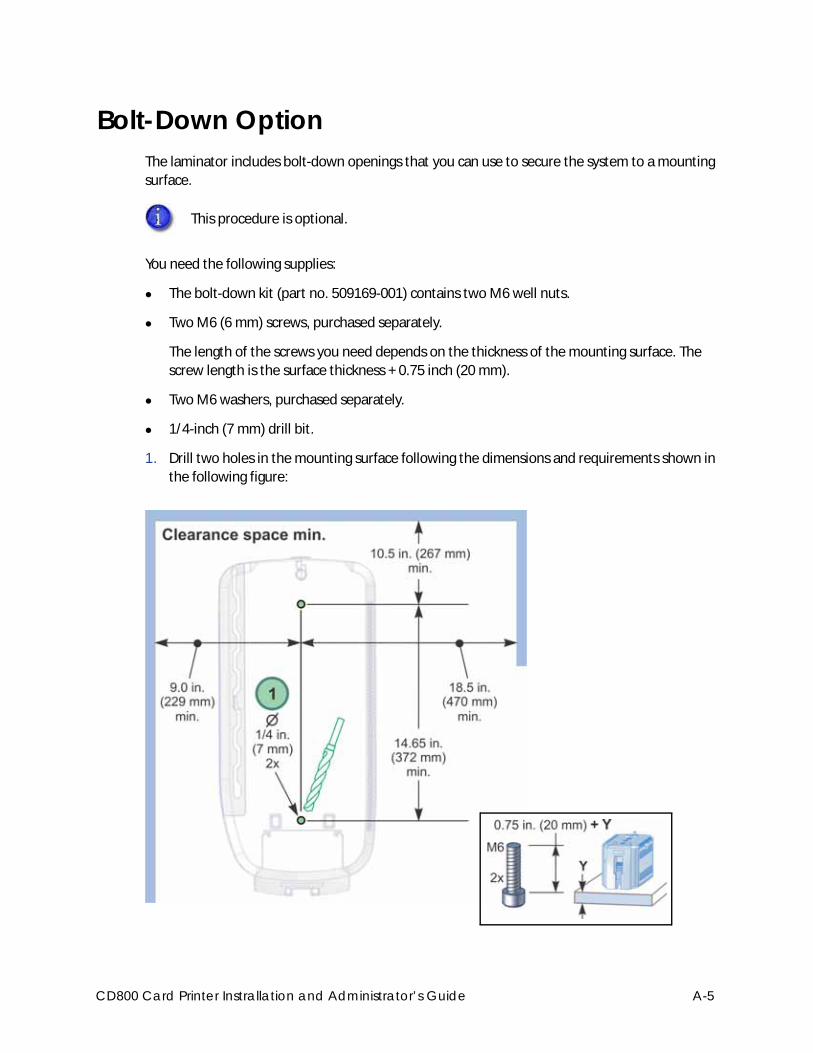
Bolt-Down OptionThe laminator includes bolt-down openings that you can use to secure the system to a mounting
surface.
You need the following supplies:
The bolt-down kit (part no. 509169-001) contains two M6 well nuts.
Two M6 (6 mm) screws, purchased separately.
The length of the screws you need depends on the thickness of the mounting surface. The
screw length is the surface thickness + 0.75 inch (20 mm).
Two M6 washers, purchased separately.
1/4-inch (7 mm) drill bit.
1. Drill two holes in the mounting surface following the dimensions and requirements shown in
the following figure:
This procedure is optional.
CD800 Card Printer Instrallation and Administrator’s Guide A-5
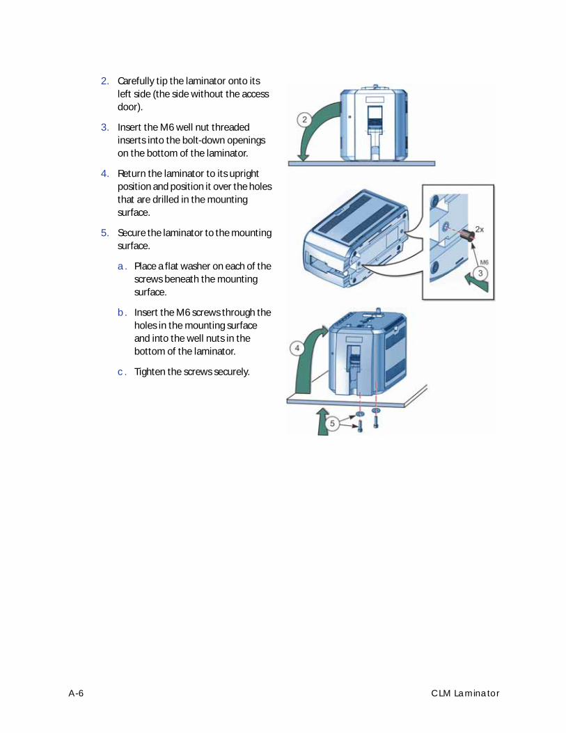
2. Carefully tip the laminator onto its
left side (the side without the access
door).
3. Insert the M6 well nut threaded
inserts into the bolt-down openings
on the bottom of the laminator.
4. Return the laminator to its upright
position and position it over the holes
that are drilled in the mounting
surface.
5. Secure the laminator to the mounting
surface.
a. Place a flat washer on each of the
screws beneath the mounting
surface.
b. Insert the M6 screws through the
holes in the mounting surface
and into the well nuts in the
bottom of the laminator.
c. Tighten the screws securely.
A-6 CLM Laminator
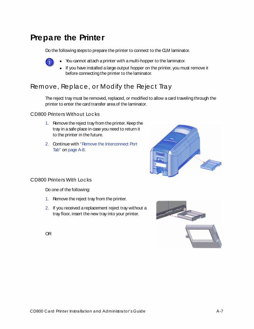
Prepare the PrinterDo the following steps to prepare the printer to connect to the CLM laminator.
Remove, Replace, or Modify the Reject TrayThe reject tray must be removed, replaced, or modified to allow a card traveling through the
printer to enter the card transfer area of the laminator.
CD800 Printers Without Locks
1. Remove the reject tray from the printer. Keep the
tray in a safe place in case you need to return it
to the printer in the future.
2. Continue with “Remove the Interconnect Port
Tab” on page A-8.
CD800 Printers With Locks
Do one of the following:
1. Remove the reject tray from the printer.
2. If you received a replacement reject tray without a
tray floor, insert the new tray into your printer.
OR
You cannot attach a printer with a multi-hopper to the laminator.
If you have installed a large output hopper on the printer, you must remove it before connecting the printer to the laminator.
CD800 Card Printer Instrallation and Administrator’s Guide A-7
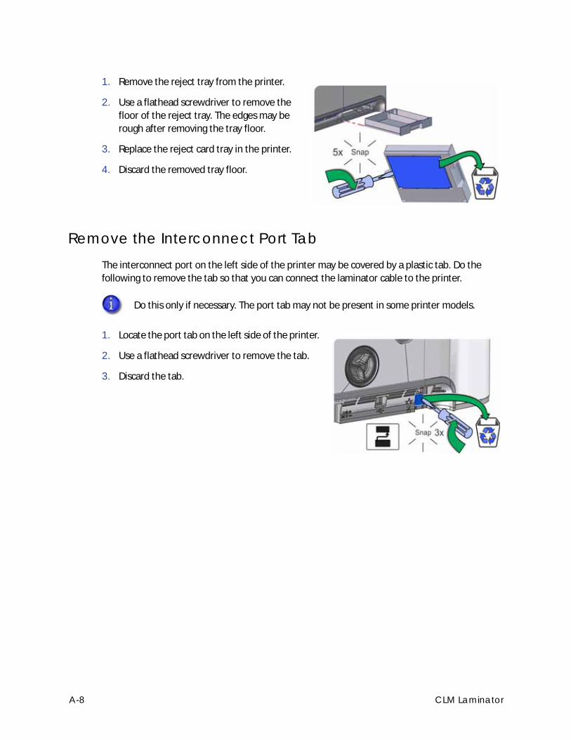
1. Remove the reject tray from the printer.
2. Use a flathead screwdriver to remove the
floor of the reject tray. The edges may be
rough after removing the tray floor.
3. Replace the reject card tray in the printer.
4. Discard the removed tray floor.
Remove the Interconnect Port TabThe interconnect port on the left side of the printer may be covered by a plastic tab. Do the
following to remove the tab so that you can connect the laminator cable to the printer.
1. Locate the port tab on the left side of the printer.
2. Use a flathead screwdriver to remove the tab.
3. Discard the tab.
Do this only if necessary. The port tab may not be present in some printer models.
A-8 CLM Laminator
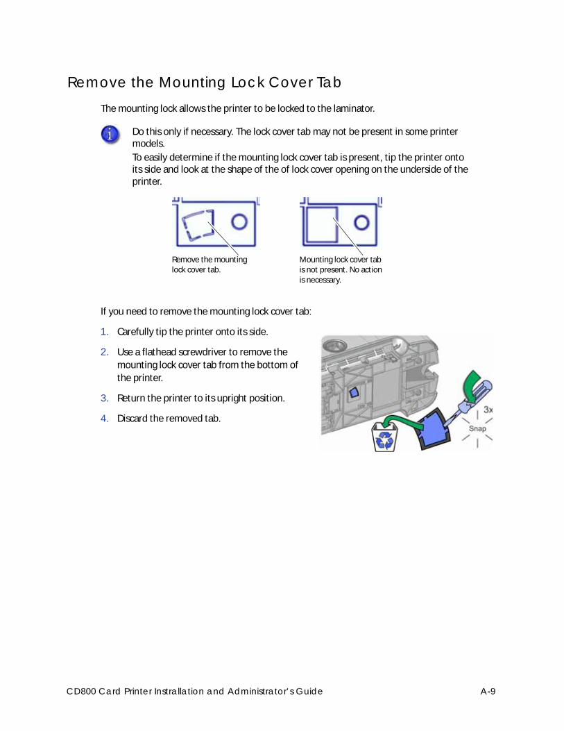
Remove the Mounting Lock Cover TabThe mounting lock allows the printer to be locked to the laminator.
If you need to remove the mounting lock cover tab:
1. Carefully tip the printer onto its side.
2. Use a flathead screwdriver to remove the
mounting lock cover tab from the bottom of
the printer.
3. Return the printer to its upright position.
4. Discard the removed tab.
Do this only if necessary. The lock cover tab may not be present in some printer models.
To easily determine if the mounting lock cover tab is present, tip the printer onto its side and look at the shape of the of lock cover opening on the underside of the printer.
Remove the mounting lock cover tab.
Mounting lock cover tab is not present. No action is necessary.
CD800 Card Printer Instrallation and Administrator’s Guide A-9
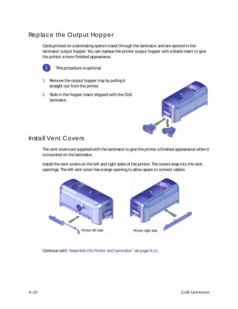
Replace the Output HopperCards printed on a laminating system travel through the laminator and are ejected in the
laminator output hopper. You can replace the printer output hopper with a blank insert to give
the printer a more finished appearance.
1. Remove the output hopper tray by pulling it
straight out from the printer.
2. Slide in the hopper insert shipped with the CLM
laminator.
Install Vent CoversThe vent covers are supplied with the laminator to give the printer a finished appearance when it
is mounted on the laminator.
Install the vent covers on the left and right sides of the printer. The covers snap into the vent
openings. The left vent cover has a large opening to allow space to connect cables.
Continue with “Assemble the Printer and Laminator” on page A-11.
This procedure is optional.
Printer right sidePrinter left side
A-10 CLM Laminator
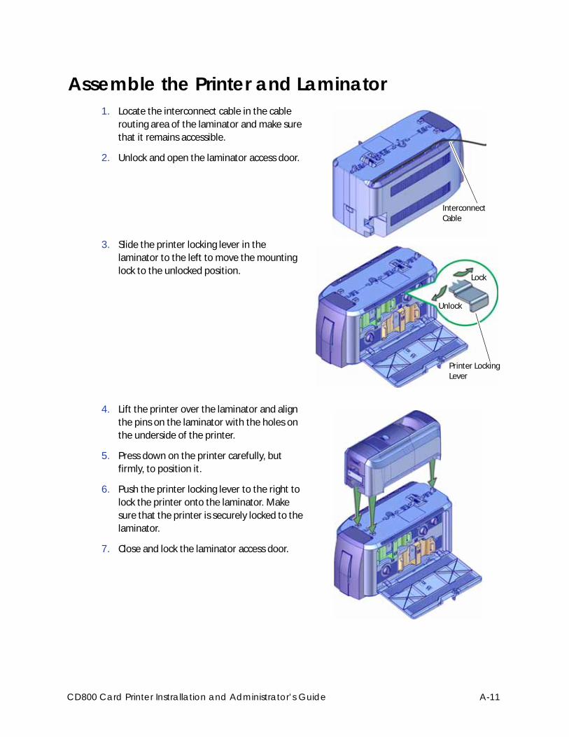
Assemble the Printer and Laminator1. Locate the interconnect cable in the cable
routing area of the laminator and make sure
that it remains accessible.
2. Unlock and open the laminator access door.
3. Slide the printer locking lever in the
laminator to the left to move the mounting
lock to the unlocked position.
4. Lift the printer over the laminator and align
the pins on the laminator with the holes on
the underside of the printer.
5. Press down on the printer carefully, but
firmly, to position it.
6. Push the printer locking lever to the right to
lock the printer onto the laminator. Make
sure that the printer is securely locked to the
laminator.
7. Close and lock the laminator access door.
Interconnect Cable
Unlock
Lock
Printer Locking Lever
CD800 Card Printer Instrallation and Administrator’s Guide A-11
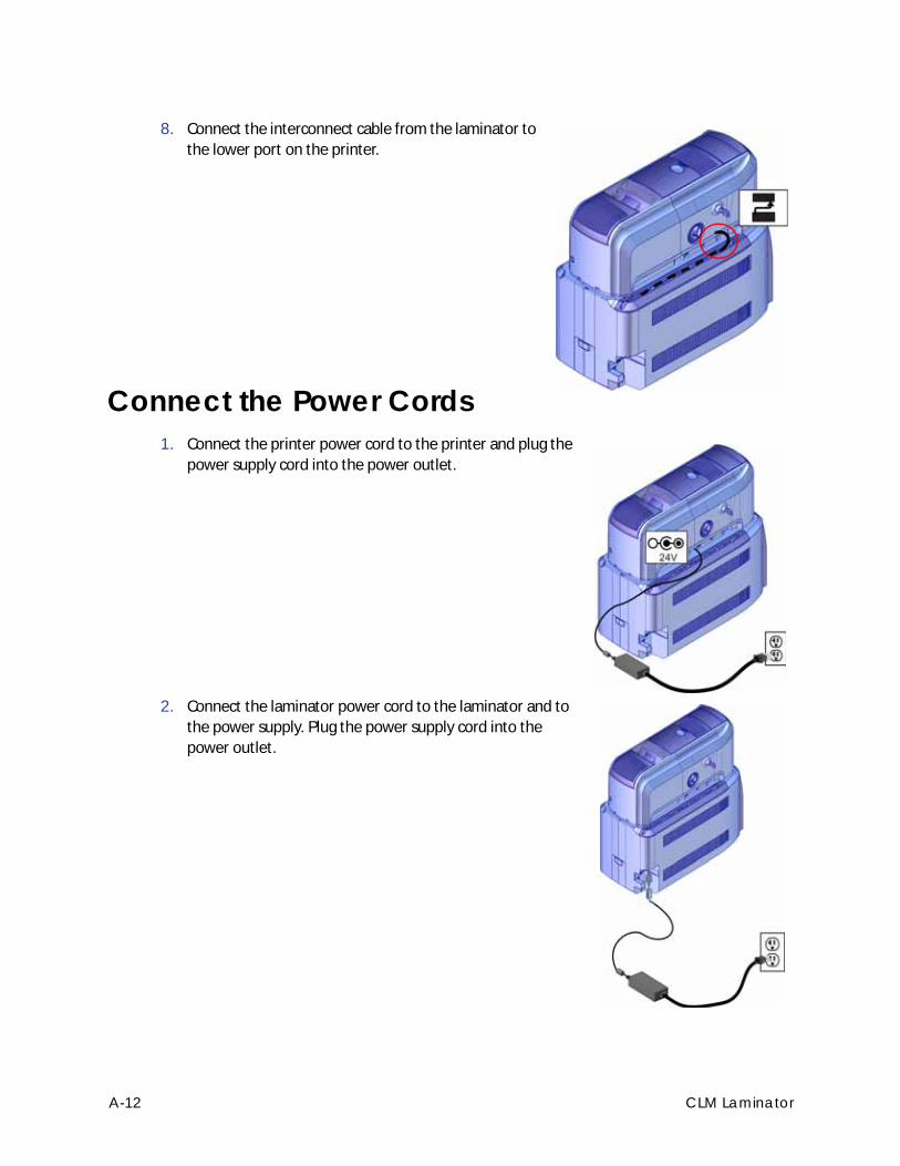
8. Connect the interconnect cable from the laminator to
the lower port on the printer.
Connect the Power Cords1. Connect the printer power cord to the printer and plug the
power supply cord into the power outlet.
2. Connect the laminator power cord to the laminator and to
the power supply. Plug the power supply cord into the
power outlet.
A-12 CLM Laminator
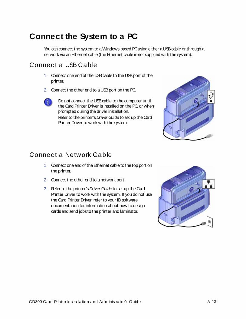
Connect the System to a PCYou can connect the system to a Windows-based PC using either a USB cable or through a
network via an Ethernet cable (the Ethernet cable is not supplied with the system).
Connect a USB Cable1. Connect one end of the USB cable to the USB port of the
printer.
2. Connect the other end to a USB port on the PC.
Connect a Network Cable1. Connect one end of the Ethernet cable to the top port on
the printer.
2. Connect the other end to a network port.
3. Refer to the printer’s Driver Guide to set up the Card
Printer Driver to work with the system. If you do not use
the Card Printer Driver, refer to your ID software
documentation for information about how to design
cards and send jobs to the printer and laminator.
Do not connect the USB cable to the computer until the Card Printer Driver is installed on the PC, or when prompted during the driver installation.
Refer to the printer’s Driver Guide to set up the Card Printer Driver to work with the system.
CD800 Card Printer Instrallation and Administrator’s Guide A-13
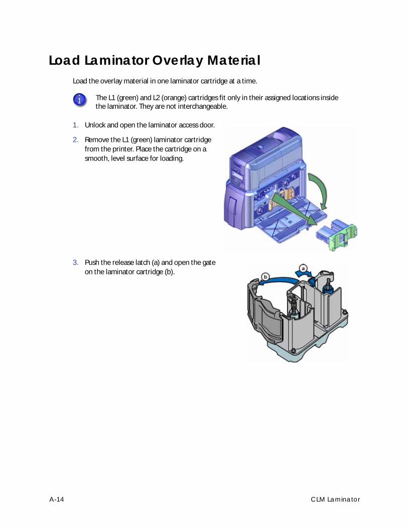
Load Laminator Overlay MaterialLoad the overlay material in one laminator cartridge at a time.
1. Unlock and open the laminator access door.
2. Remove the L1 (green) laminator cartridge
from the printer. Place the cartridge on a
smooth, level surface for loading.
3. Push the release latch (a) and open the gate
on the laminator cartridge (b).
The L1 (green) and L2 (orange) cartridges fit only in their assigned locations inside the laminator. They are not interchangeable.
A-14 CLM Laminator
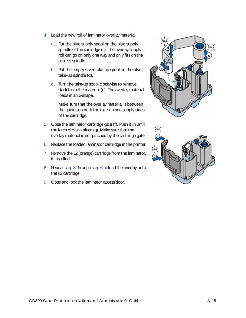
4. Load the new roll of laminator overlay material.
a. Put the blue supply spool on the blue supply
spindle of the cartridge (c). The overlay supply
roll can go on only one way and only fits on the
correct spindle.
b. Put the empty silver take-up spool on the silver
take-up spindle (d).
c. Turn the take-up spool clockwise to remove
slack from the material (e). The overlay material
loads in an S-shape.
Make sure that the overlay material is between
the guides on both the take-up and supply sides
of the cartridge.
5. Close the laminator cartridge gate (f). Push it in until
the latch clicks in place (g). Make sure that the
overlay material is not pinched by the cartridge gate.
6. Replace the loaded laminator cartridge in the printer.
7. Remove the L2 (orange) cartridge from the laminator,
if installed.
8. Repeat step 3 through step 6 to load the overlay onto
the L2 cartridge.
9. Close and lock the laminator access door.
CD800 Card Printer Instrallation and Administrator’s Guide A-15
Power On the SystemPress the power button on the front panel of the printer to power on the system. The printer and
laminator perform internal checks and initialize supplies.
The laminator contains heaters for the L1 and L2 (if installed) cartridges, and for the impresser if
one is installed. It can take several minutes for the heaters to reach their correct operating
temperature before the system is ready to print cards.
Print a Test CardAfter you set up the printer, print several test cards to determine how well the laminator applies
the overlay material to the card. You may need to print multiple test cards to make sure that the
overlay is positioned correctly. The card stock, the card design, and the printer’s environment can
influence the appearance of cards.
Use the Card Printer DriverRefer to the printer’s Driver Guide for information about how to set up lamination preferences
and print a driver test card.
If message 222, Firmware version mismatch, displays on the printer LCD, refer to the CD800 Card Printer CLM Laminator Quick Install and Upgrade Guide for information about updating the printer and laminator firmware versions.
The laminator has a power-save feature that powers off the heaters after the printer has been idle for a specified period of time. If the timeout period expires, it can take several minutes for the laminator heaters to return to their operating temperature when a card is sent to the printer. The front panel displays the message Busy Warming up during this time. You can change the timeout period using the Printer Manager Laminator setting. Refer to “Laminator” on page 76 for more information about using Printer Manager.
If your system includes the optional second laminator (L2), make sure that the laminator cartridge is always installed, even if the cartridge is not loaded with overlay material. If the cartridge is not in place, cards are not supported as they travel through the system, and can fall into the bottom of the laminator.
A-16 CLM Laminator
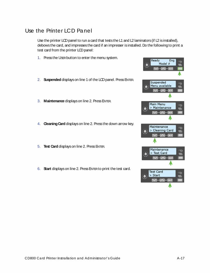
Use the Printer LCD PanelUse the printer LCD panel to run a card that tests the L1 and L2 laminators (if L2 is installed),
debows the card, and impresses the card if an impresser is installed. Do the following to print a
test card from the printer LCD panel:
1. Press the USER button to enter the menu system.
2. Suspended displays on line 1 of the LCD panel. Press ENTER.
3. Maintenance displays on line 2. Press ENTER.
4. Cleaning Card displays on line 2. Press the down arrow key.
5. Test Card displays on line 2. Press ENTER.
6. Start displays on line 2. Press ENTER to print the test card.
CD800 Card Printer Instrallation and Administrator’s Guide A-17
Use Printer ManagerUse Printer Manager to print test cards and fine-tune your lamination settings. Refer to
Chapter 3: "Printer Manager” for complete information about accessing and using Printer
Manager. Do the following to print a test card from Printer Manager:
1. Log on to Printer Manager.
a. Do one of the following:
Open an Internet browser and enter the printer IP address:
IPv4: Enter the address using the following format: https://xxx.xxx.xxx.xxx.
For example, https://172.12.3.45.
IPv6: Enter the address using the following format:
https://[xxxx:xxxx:xxxx:xxxx:xxxx:xxxx:xxxx:xxxx]/
For example, https://[2001:0db8:1234:5678:90ab:def0:1234:5678]/
OR
Open the Printer Properties window for the card printer and select the Printer
Status tab.
Click Configure Printer to launch Printer Manager in your default browser.
If the browser indicates a problem with the website security certificate, continue to the
website to access Printer Manager.
You must enclose the IPv6 address in brackets ( [ and ] ).
A-18 CLM Laminator
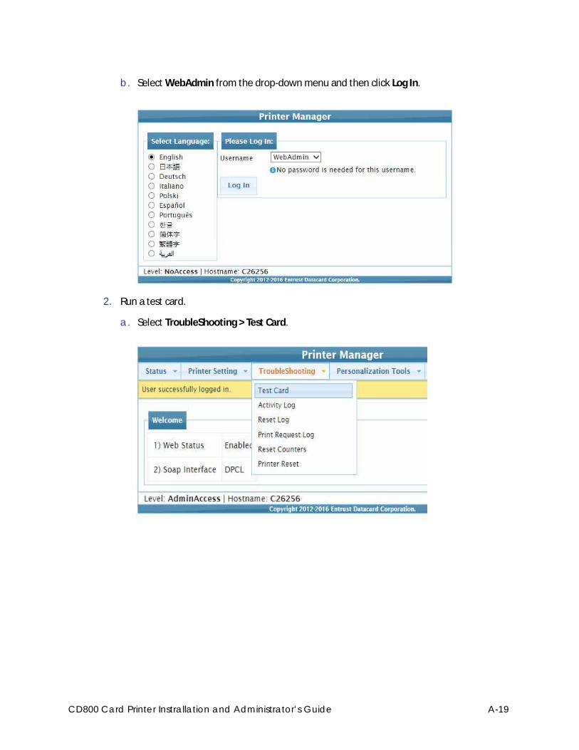
b. Select WebAdmin from the drop-down menu and then click Log In.
2. Run a test card.
a. Select TroubleShooting > Test Card.
CD800 Card Printer Instrallation and Administrator’s Guide A-19
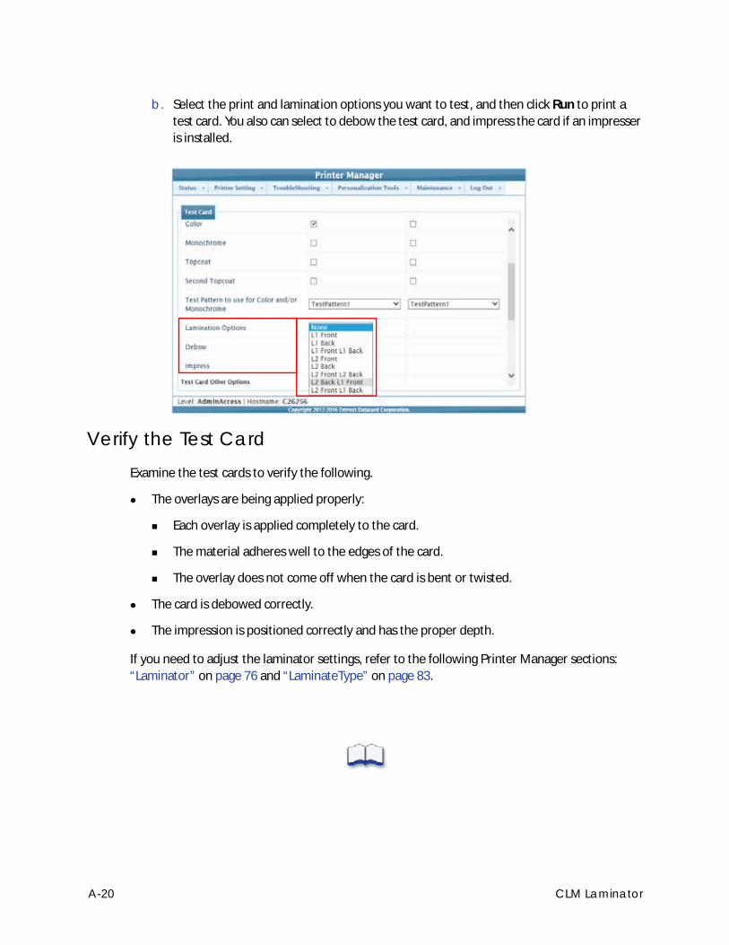
b. Select the print and lamination options you want to test, and then click Run to print a
test card. You also can select to debow the test card, and impress the card if an impresser
is installed.
Verify the Test CardExamine the test cards to verify the following.
The overlays are being applied properly:
Each overlay is applied completely to the card.
The material adheres well to the edges of the card.
The overlay does not come off when the card is bent or twisted.
The card is debowed correctly.
The impression is positioned correctly and has the proper depth.
If you need to adjust the laminator settings, refer to the following Printer Manager sections:
“Laminator” on page 76 and “LaminateType” on page 83.
A-20 CLM Laminator