Embed Size (px)
Citation preview
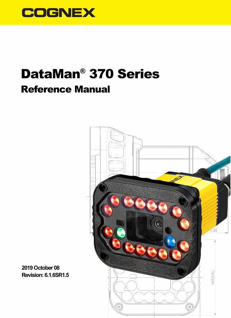
DataMan® 370 SeriesReference Manual
2019October08Revision:6.1.6SR1.5

Legal NoticesThe software described in this document is furnished under license, and may be used or copied only in accordance withthe terms of such license and with the inclusion of the copyright notice shown on this page. Neither the software, thisdocument, nor any copies thereof may be provided to, or otherwise made available to, anyone other than the licensee.Title to, and ownership of, this software remains with Cognex Corporation or its licensor. Cognex Corporation assumesno responsibility for the use or reliability of its software on equipment that is not supplied by Cognex Corporation.Cognex Corporation makes no warranties, either express or implied, regarding the described software, itsmerchantability, non-infringement or its fitness for any particular purpose.
The information in this document is subject to change without notice and should not be construed as a commitment byCognex Corporation. Cognex Corporation is not responsible for any errors that may be present in either this document orthe associated software.
Companies, names, and data used in examples herein are fictitious unless otherwise noted. No part of this documentmay be reproduced or transmitted in any form or by any means, electronic or mechanical, for any purpose, nortransferred to any other media or language without the written permission of Cognex Corporation.
Copyright © 2019. Cognex Corporation. All Rights Reserved.
Portions of the hardware and software provided by Cognex may be covered by one or more U.S. and foreign patents, aswell as pending U.S. and foreign patents listed on the Cognex web site at: cognex.com/patents.
The following are registered trademarks of Cognex Corporation:
Cognex, 2DMAX, Advantage, AlignPlus, Assemblyplus, Check it with Checker, Checker, Cognex Vision for Industry,Cognex VSOC, CVL, DataMan, DisplayInspect, DVT, EasyBuilder, Hotbars, IDMax, In-Sight, Laser Killer, MVS-8000,OmniView, PatFind, PatFlex, PatInspect, PatMax, PatQuick, SensorView, SmartView, SmartAdvisor, SmartLearn,UltraLight, Vision Solutions, VisionPro, VisionView
The following are trademarks of Cognex Corporation:
The Cognex logo, 1DMax, 3D-Locate, 3DMax, BGAII, CheckPoint, Cognex VSoC, CVC-1000, FFD, iLearn, In-Sight(design insignia with cross-hairs), In-Sight 2000, InspectEdge, Inspection Designer, MVS, NotchMax, OCRMax,PatMax RedLine, ProofRead, SmartSync, ProfilePlus, SmartDisplay, SmartSystem, SMD4, VisiFlex, Xpand
Portions copyright © Microsoft Corporation. All rights reserved.
Portions copyright © MadCap Software, Inc. All rights reserved.
Other product and company trademarks identified herein are the trademarks of their respective owners.
2
Legal Notices
Table of ContentsLegal Notices 2Table of Contents 3Symbols 5Getting Started 6About the DataMan 370 Readers 6Configuration 6DataMan 370 Series Accessories 8Lens Options 8Lens Covers and Internal Illumination 8High Power Illumination Accessories 9High Power Integrated Torch Accessories 10External Lights 11Field of View Expanders 12Cables and Power Supply 12Mounting Brackets 13
DataMan 370 Systems 14
Setting Up Your DataMan 370 15Reader Layout 15Dimensions 16DataMan 370 17DataMan 370 with High Power Integrated Light (HPIL) 17DataMan 370 with High Power Illumination Accessory (HPIA) 17DataMan 370 Series with High Power Integrated Torch (HPIT) 18
Assembling DataMan 370 Series Lens and Lights 18Installing the Liquid Lens module with High Power Integrated Light (HPIL) 19Installing a Lens with High Power Illumination Accessory (HPIA) 23Installing High Power Integrated Torch (HPIT) 25Installing a C-Mount Lens 28Connecting External Illumination to DataMan 370 31
Mounting the Reader 33Setting Focus 36Liquid Lens 36Manual Focus Lens 38Focus Feedback 38Best Practices 39
Field of View and Reading Distances 40Reading Distance and Field of View (DataMan 370 Readers with a 10mmHigh-Speed Liquid Lens) 40Reading Distance and Field of View (DataMan 370 Readers with a 16mmHigh-Speed Liquid Lens) 40Reading Distance and Field of View (DataMan 370 Readers with a 24mmHigh-Speed Liquid Lens) 41
Maintenance 42Replacing the SD Card 42
Additional Information 44DataMan 370 Series Specifications 44DataMan 370 Series Imager Specifications 45LED and LaserWavelengths 45
3
Table of Contents
Using Your DataMan 370 46Reading your First Code 46DataMan 370 Triggering 49External Triggers 50Training the Reader 51Training Feedback 51Incremental Training for Multiple Symbologies 52
Industrial Protocols 53Advanced Features 53DataMan 370 Image Filtering 54Package Detection Support 55
DataMan 370 Series Multi-Reader Sync Option 55
Connections, Optics, and Lighting 57External Light Control (CCB-M12XFLY-05) 575m Breakout Cable (CCBL-05-01) 585m Breakout Cable (CCB-M12x12Fy-xx) 5915m Breakout Cable (CCB-PWRIO-XX) 60Acquisition Trigger 60High-SpeedOutputs 61High-SpeedOutput Wiring 625m RS-232 Connection Cable (CCB-M12XDB9Y-05) 63Ethernet X-coded to RJ45 Cable (CCB-84901-y00x-xx) 64
Cleaning and Maintenance 65Cleaning the Reader Housing 65Cleaning the Reader Lens Cover 65
Compliance Information, Warnings and Notices 66Precautions 66Regulations/Conformity 67For European Community Users 67
Reader Programming Codes 68
4
Table of Contents

SymbolsThe following symbols indicate safety precautions and supplemental information:
WARNING: This symbol indicates a hazard that could cause death, serious personal injury or electrical shock.
CAUTION: This symbol indicates a hazard that could result in property damage.
Note: This symbol indicates additional information about a subject.
Tip: This symbol indicates suggestions and shortcuts that might not otherwise be apparent.
5
Symbols
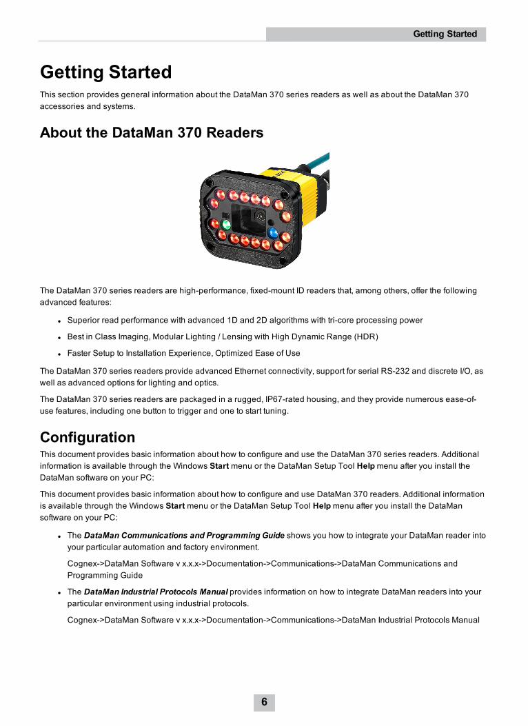
Getting StartedThis section provides general information about the DataMan 370 series readers as well as about the DataMan 370accessories and systems.
About the DataMan 370 Readers
The DataMan 370 series readers are high-performance, fixed-mount ID readers that, among others, offer the followingadvanced features:
l Superior read performance with advanced 1D and 2D algorithms with tri-core processing power
l Best in Class Imaging, Modular Lighting / Lensing with High Dynamic Range (HDR)
l Faster Setup to Installation Experience, Optimized Ease of Use
The DataMan 370 series readers provide advanced Ethernet connectivity, support for serial RS-232 and discrete I/O, aswell as advanced options for lighting and optics.
The DataMan 370 series readers are packaged in a rugged, IP67-rated housing, and they provide numerous ease-of-use features, including one button to trigger and one to start tuning.
ConfigurationThis document provides basic information about how to configure and use the DataMan 370 series readers. Additionalinformation is available through the Windows Start menu or the DataMan Setup Tool Helpmenu after you install theDataMan software on your PC:
This document provides basic information about how to configure and use DataMan 370 readers. Additional informationis available through the Windows Start menu or the DataMan Setup Tool Helpmenu after you install the DataMansoftware on your PC:
l The DataMan Communications and Programming Guide shows you how to integrate your DataMan reader intoyour particular automation and factory environment.
Cognex->DataMan Software v x.x.x->Documentation->Communications->DataMan Communications andProgramming Guide
l The DataMan Industrial Protocols Manual provides information on how to integrate DataMan readers into yourparticular environment using industrial protocols.
Cognex->DataMan Software v x.x.x->Documentation->Communications->DataMan Industrial Protocols Manual
6
Getting Started

l The DataMan Reader Configuration Codes document provides printable 2-D codes that you can use toconfigure the DataMan reader.
Cognex->DataMan Software v x.x.x->Documentation->English->Reader Configuration Codes
l The DM370 Quick Reference Guide provides essential information about the DM370 readers.
Cognex->DataMan Software v x.x.x->Documentation->English->DM370 Series->DM370 Quick Reference Guide
l The DataMan Fixed-Mount Readers Reference is a complete online hardware reference for the DataMan fixed-mount ID readers.
Cognex->DataMan Software v x.x.x->Documentation->English->DM370 ->Fixed-Mount Reference Manual
l The DataMan Questions and Answers document provides context-sensitive information. You can view this helpinside the DataMan Setup Tool or as a stand-alone help file.
Cognex->DataMan Software v x.x.x->Documentation->DM370->Questions and Answers
l The DataMan Control Commands lists DataMan Control Commands with all relevant information. You can viewthis help inside the Setup Tool or as a stand-alone help file.
Cognex->DataMan Software v x.x.x->Documentation->English->DataMan Control Commands
l The Setup Tool Reference Manual describes the user interface of the DataMan Setup Tool software.
Cognex->DataMan Software v x.x.x->Documentation->English->Setup Tool Reference Manual
l The Release Notes list detailed system requirements and additional information about this DataMan softwarerelease.
Cognex->DataMan Software v x.x.x->Documentation->DataMan v x.x.x Release Notes
7
Getting Started
DataMan 370 Series Accessories
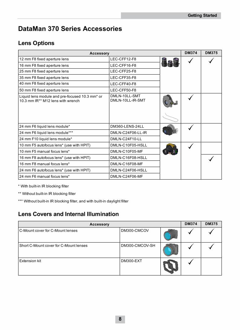
Lens OptionsAccessory DM374 DM375
12 mm F8 fixed aperture lens LEC-CFF12-F8
16 mm F8 fixed aperture lens LEC-CFF16-F825 mm F8 fixed aperture lens LEC-CFF25-F8
35 mm F8 fixed aperture lens LEC-CFF35-F840 mm F8 fixed aperture lens LEC-CFF40-F850 mm F8 fixed aperture lens LEC-CFF50-F8Liquid lens module and pre-focused 10.3 mm* or10.3 mm IR** M12 lens with wrench
DMLN-10LL-SMTDMLN-10LL-IR-SMT
24 mm F6 liquid lens module* DM360-LENS-24LL24 mm F6 liquid lens module*** DMLN-C24F06-LL-IR24 mm F10 liquid lens module* DMLN-C24F10-LL10 mm F5 autofocus lens* (use with HPIT) DMLN-C10F05-HSLL10 mm F5 manual focus lens* DMLN-C10F05-MF16 mm F8 autofocus lens* (use with HPIT) DMLN-C16F08-HSLL16 mm F8 manual focus lens* DMLN-C16F08-MF24 mm F6 autofocus lens* (use with HPIT) DMLN-C24F06-HSLL24 mm F6 manual focus lens* DMLN-C24F06-MF
* With built-in IR blocking filter
** Without built-in IR blocking filter
*** Without built-in IR blocking filter, and with built-in daylight filter
Lens Covers and Internal IlluminationAccessory DM374 DM375
C-Mount cover for C-Mount lenses DM300-CMCOV
Short C-Mount cover for C-Mount lenses DM300-CMCOV-SH
Extension kit DM300-EXT
8
Getting Started
Accessory DM374 DM375Red LED HPIL, ESD safe, 10.3 mm lens(Risk Group Red LEDExempt acc. IEC 62471, Risk Group Green LEDAimerExempt acc. IEC 62471)
DM360-HPIL-RE
Polarized red LED HPIL, ESD safe, 10.3 mm lens(Risk Group Red LEDExempt acc. IEC 62471, Risk Group Green LEDAimerExempt acc. IEC 62471)
DM360-HPIL-RE-P
White LED HPIL, ESD safe, 10.3 mm lens(Risk Group White LED low risk acc. IEC 62471, Risk Group Green LEDAimerExempt acc. IEC 62471)
DM360-HPIL-WHI
Red LED HPIL, ESD safe, 24 mm liquid lens(Risk Group Red LEDExempt acc. IEC 62471, Risk Group Green LEDAimerExempt acc. IEC 62471)
DMLT-HPIL-RE
Polarized red LED HPIL, ESD safe, 24 mm liquid lens(Risk Group Red LEDExempt acc. IEC 62471, Risk Group Green LEDAimerExempt acc. IEC 62471)
DMLT-HPIL-RE-P
White LED HPIL, ESD safe, 24 mm liquid lens(Risk Group White LED low risk acc. IEC 62471, Risk Group Green LEDAimerExempt acc. IEC 62471)
DMLT-HPIL-WHI
Infrared LED HPIL, ESD safe, 10.3 & 24 mm liquid lens(Risk Group IR LEDExempt acc. IEC 62471, Risk Group Green LEDAimerExempt acc. IEC 62471)
DMLT-HPIL-IR-W
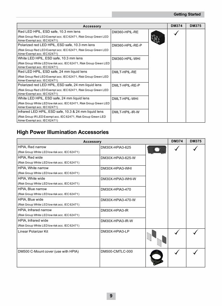
High Power Illumination AccessoriesAccessory DM374 DM375
HPIA, Red narrow(Risk Group White LED low risk acc. IEC 62471)
DM30X-HPIA3-625
HPIA, Red wide(Risk Group White LED low risk acc. IEC 62471)
DM30X-HPIA3-625-W
HPIA, White narrow(Risk Group White LED low risk acc. IEC 62471)
DM30X-HPIA3-WHI
HPIA, White wide(Risk Group White LED low risk acc. IEC 62471)
DM30X-HPIA3-WHI-W
HPIA, Blue narrow(Risk Group White LED low risk acc. IEC 62471)
DM30X-HPIA3-470
HPIA, Blue wide(Risk Group White LED low risk acc. IEC 62471)
DM30X-HPIA3-470-W
HPIA, Infrared narrow(Risk Group White LED low risk acc. IEC 62471)
DM30X-HPIA3-IR
HPIA, Infrared wide(Risk Group White LED low risk acc. IEC 62471)
DM30X-HPIA3-IR-W
Linear Polarizer Kit DM30X-HPIA3-LP
DM500 C-Mount cover (use with HPIA) DM500-CMTLC-000
9
Getting Started

Accessory DM374 DM375
DM500 Lens cover extender DM500-LNSEXT-000
Laser aimer (use with HPIA) DM300-AIMER-00
WARNING: For DM300-AIMER-00 equipped with laser: This device has been tested in accordance with IEC60825-1 3rd ed., 2014., and has beencertified to be under the limits of a Class 2 Laser device.
High Power Integrated Torch AccessoriesAccessory DM374 DM375
HPIT, Red wide, 10 and 16 mm high-speed liquid lens(Risk Group Red LEDexempt risk acc. IEC 62471)
DMLT-HPIT-RE-W
HPIT, Red standard, 24 mm high-speed liquid lens(Risk Group Red LEDexempt risk acc. IEC 62471)
DMLT-HPIT-RE-S
HPIT, White wide, 10 and 16 mm high-speed liquid lens(Risk Group White LED low risk acc. IEC 62471)
DMLT-HPIT-WHI-W
HPIT, White standard, 24 mm high-speed liquid lens(Risk Group White LED low risk acc. IEC 62471)
DMLT-HPIT-WHI-S
Polarized front cover DMLA-HPIT-PLCOV
Clear front cover DMLA-HPIT-CLCOV
Diffuse front cover DMLA-HPIT-DLCOV
Adapter (includes PCB light port adapter) DMLA-HPIT-ADAP370
WARNING: For HPIT equipped with a time-of-flight sensor: This device has been tested in accordance with IEC60825-1 3rd ed., 2014., and has beencertified to be under the limits of a Class 1 Laser device. Wavelength 930-950 nm invisible laser radiation.
WARNING: For HPIT equipped with a target aimer: This device has been tested in accordance with IEC60825-1 3rd ed., 2014., and has been certifiedto be under the limits of a Class 2 Laser device. Wavelength 515 nm laser radiation.
10
Getting Started
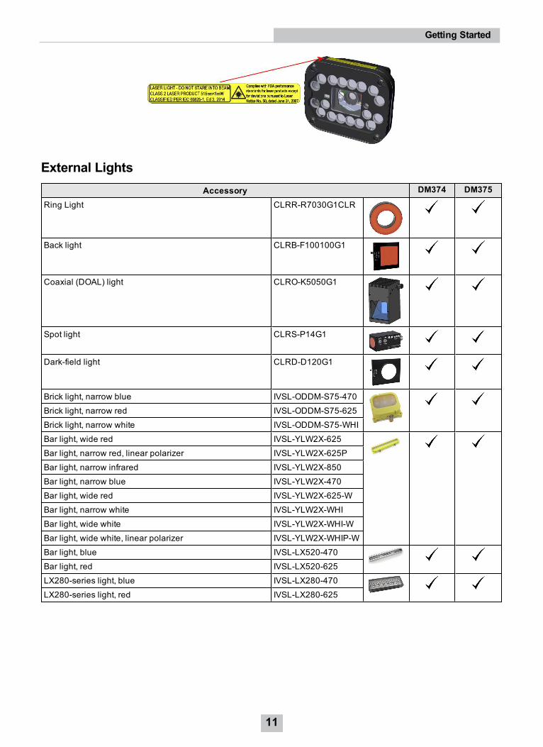
External LightsAccessory DM374 DM375
Ring Light CLRR-R7030G1CLR
Back light CLRB-F100100G1
Coaxial (DOAL) light CLRO-K5050G1
Spot light CLRS-P14G1
Dark-field light CLRD-D120G1
Brick light, narrow blue IVSL-ODDM-S75-470Brick light, narrow red IVSL-ODDM-S75-625Brick light, narrow white IVSL-ODDM-S75-WHIBar light, wide red IVSL-YLW2X-625Bar light, narrow red, linear polarizer IVSL-YLW2X-625PBar light, narrow infrared IVSL-YLW2X-850Bar light, narrow blue IVSL-YLW2X-470Bar light, wide red IVSL-YLW2X-625-WBar light, narrow white IVSL-YLW2X-WHIBar light, wide white IVSL-YLW2X-WHI-WBar light, wide white, linear polarizer IVSL-YLW2X-WHIP-WBar light, blue IVSL-LX520-470Bar light, red IVSL-LX520-625LX280-series light, blue IVSL-LX280-470LX280-series light, red IVSL-LX280-625
11
Getting Started
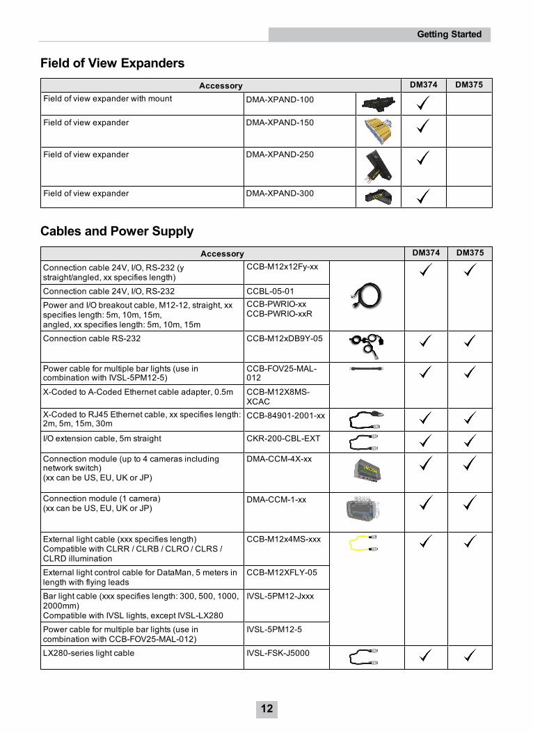
Field of View ExpandersAccessory DM374 DM375
Field of view expander with mount DMA-XPAND-100
Field of view expander DMA-XPAND-150
Field of view expander DMA-XPAND-250
Field of view expander DMA-XPAND-300
Cables and Power SupplyAccessory DM374 DM375
Connection cable 24V, I/O, RS-232 (ystraight/angled, xx specifies length)
CCB-M12x12Fy-xx
Connection cable 24V, I/O, RS-232 CCBL-05-01Power and I/O breakout cable, M12-12, straight, xxspecifies length: 5m, 10m, 15m,angled, xx specifies length: 5m, 10m, 15m
CCB-PWRIO-xxCCB-PWRIO-xxR
Connection cable RS-232 CCB-M12xDB9Y-05
Power cable for multiple bar lights (use incombination with IVSL-5PM12-5)
CCB-FOV25-MAL-012
X-Coded to A-Coded Ethernet cable adapter, 0.5m CCB-M12X8MS-XCAC
X-Coded to RJ45 Ethernet cable, xx specifies length:2m, 5m, 15m, 30m
CCB-84901-2001-xx
I/O extension cable, 5m straight CKR-200-CBL-EXT
Connection module (up to 4 cameras includingnetwork switch)(xx can be US, EU, UK or JP)
DMA-CCM-4X-xx
Connection module (1 camera)(xx can be US, EU, UK or JP)
DMA-CCM-1-xx
External light cable (xxx specifies length)Compatible with CLRR / CLRB / CLRO / CLRS /CLRD illumination
CCB-M12x4MS-xxx
External light control cable for DataMan, 5 meters inlength with flying leads
CCB-M12XFLY-05
Bar light cable (xxx specifies length: 300, 500, 1000,2000mm)Compatible with IVSL lights, except IVSL-LX280
IVSL-5PM12-Jxxx
Power cable for multiple bar lights (use incombination with CCB-FOV25-MAL-012)
IVSL-5PM12-5
LX280-series light cable IVSL-FSK-J5000
12
Getting Started

Mounting BracketsAccessory DM374 DM375
Flat Mounting Bracket DMBK-370-MNT
Pivot Mounting Bracket DM100-PIVOTM-00
External Heat Sink DMA-HEATSINK-000
13
Getting Started
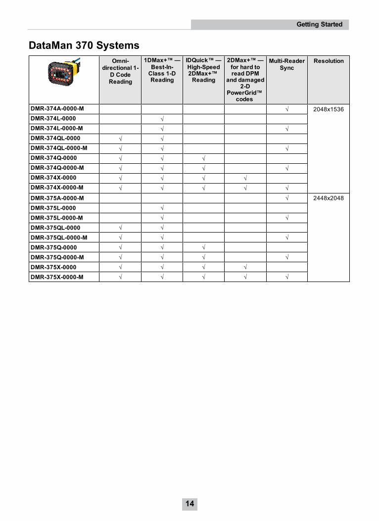
DataMan 370 SystemsOmni-
directional 1-D CodeReading
1DMax+™—Best-In-Class 1-DReading
IDQuick™—High-Speed2DMax+™Reading
2DMax+™—for hard toread DPM
and damaged2-D
PowerGrid™codes
Multi-ReaderSync
Resolution
DMR-374A-0000-M √ 2048x1536DMR-374L-0000 √DMR-374L-0000-M √ √DMR-374QL-0000 √ √DMR-374QL-0000-M √ √ √DMR-374Q-0000 √ √ √DMR-374Q-0000-M √ √ √ √DMR-374X-0000 √ √ √ √DMR-374X-0000-M √ √ √ √ √DMR-375A-0000-M √ 2448x2048DMR-375L-0000 √DMR-375L-0000-M √ √DMR-375QL-0000 √ √DMR-375QL-0000-M √ √ √DMR-375Q-0000 √ √ √DMR-375Q-0000-M √ √ √ √DMR-375X-0000 √ √ √ √DMR-375X-0000-M √ √ √ √ √
14
Getting Started
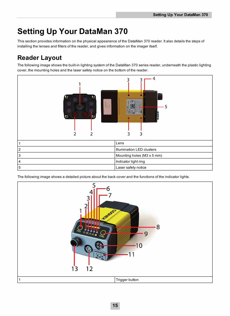
Setting Up Your DataMan 370This section provides information on the physical appearance of the DataMan 370 reader. It also details the steps ofinstalling the lenses and filters of the reader, and gives information on the imager itself.
Reader LayoutThe following image shows the built-in lighting system of the DataMan 370 series reader, underneath the plastic lightingcover, the mounting holes and the laser safety notice on the bottom of the reader.
1 Lens
2 Illumination LED clusters3 Mounting holes (M3 x 5 mm)4 Indicator light ring5 Laser safety notice
The following image shows a detailed picture about the back cover and the functions of the indicator lights.
1 Trigger button
15
Setting Up Your DataMan 370
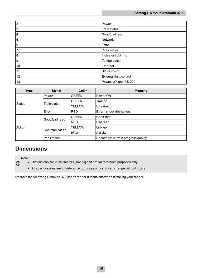
2 Power3 Train status4 Good/bad read5 Network6 Error7 Peak meter8 Indicator light ring9 Tuning button10 Ethernet11 SD card slot12 External light control13 Power, I/O, and RS-232
Type Signal Color Meaning
Status
Power GREEN Power ON
Train statusGREEN TrainedYELLOW Untrained
Error RED Error - check device log
Action
Good/bad readGREEN Good readRED Bad read
CommunicationYELLOW Link upblink Activity
Peak meter - Decode yield, train progress/quality
DimensionsNote:
l Dimensions are in millimeters [inches] and are for reference purposes only.
l All specifications are for reference purposes only and can change without notice.
Observe the following DataMan 370 series reader dimensions when installing your reader.
16
Setting Up Your DataMan 370
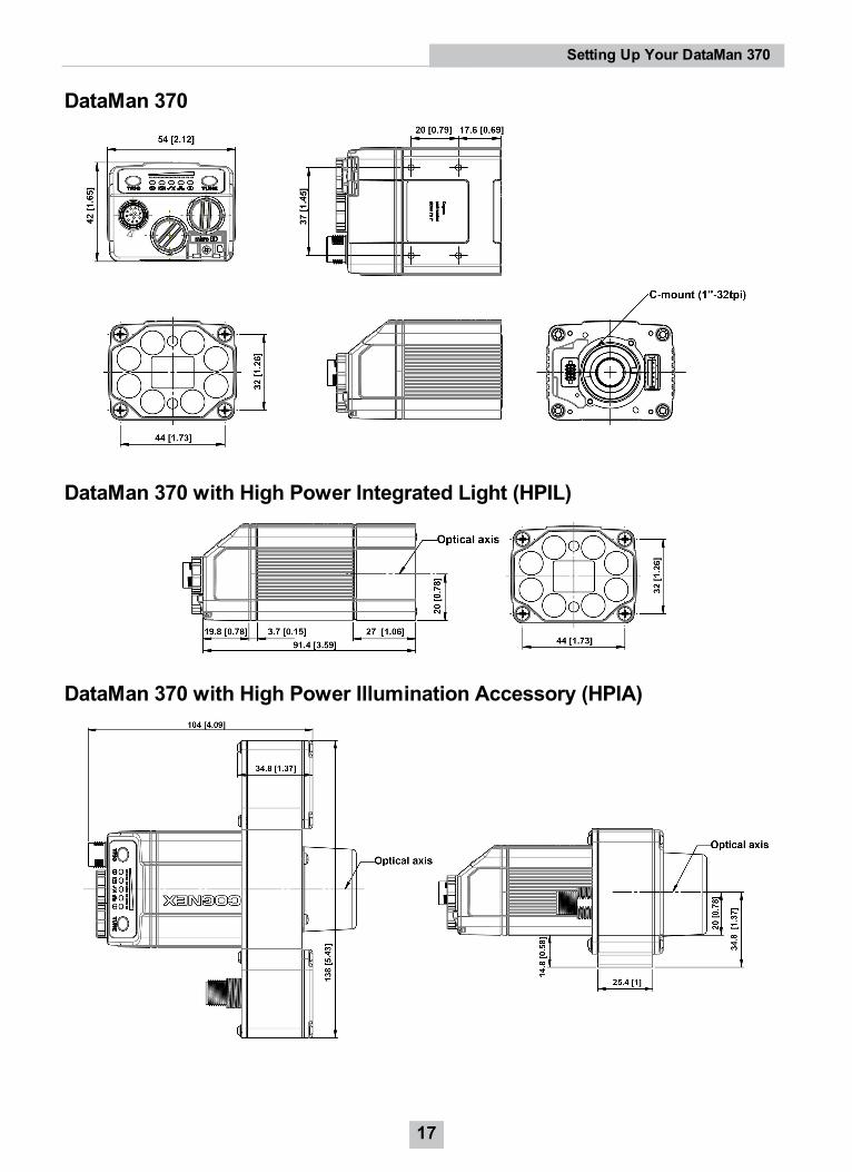
DataMan 370
DataMan 370 with High Power Integrated Light (HPIL)
DataMan 370 with High Power Illumination Accessory (HPIA)
17
Setting Up Your DataMan 370
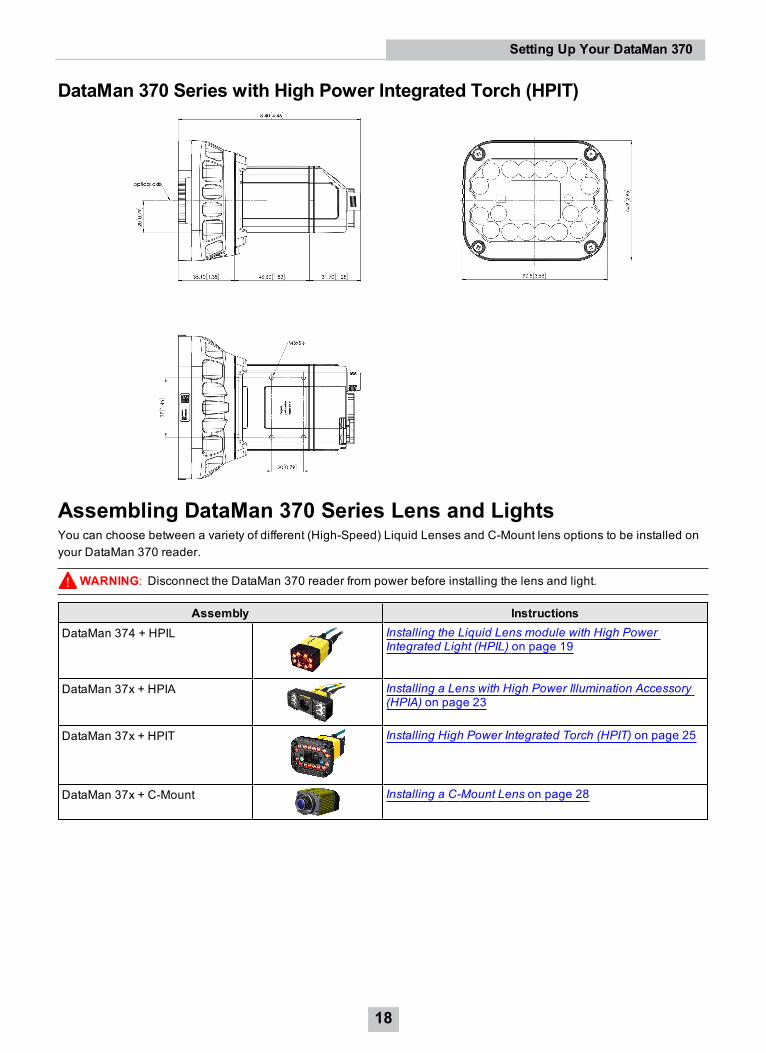
DataMan 370 Series with High Power Integrated Torch (HPIT)
Assembling DataMan 370 Series Lens and LightsYou can choose between a variety of different (High-Speed) Liquid Lenses and C-Mount lens options to be installed onyour DataMan 370 reader.
WARNING: Disconnect the DataMan 370 reader from power before installing the lens and light.
Assembly InstructionsDataMan 374 + HPIL Installing the Liquid Lens module with High Power
Integrated Light (HPIL) on page 19
DataMan 37x + HPIA Installing a Lens with High Power Illumination Accessory(HPIA) on page 23
DataMan 37x + HPIT Installing High Power Integrated Torch (HPIT) on page 25
DataMan 37x + C-Mount Installing a C-Mount Lens on page 28
18
Setting Up Your DataMan 370
Installing the Liquid Lens module with High Power Integrated Light (HPIL)Possible hardware configurations using a liquid lens module with a DataMan 370 reader:
System Lens HPIL typeDM374 DM300-LENS-10LL DM360-HPIL-RE
DM360-HPIL-RE-PDM360-HPIL-WHI
DM300-LENS-10LL-IR DMLT-HPIL-IR-WDMLN-C24F10-LLDM360-LENS-24LL
DMLT-HPIL-REDMLT-HPIL-RE-PDMLT-HPIL-WHI
DMLN-C24F06-LL-IR DMLT-HPIL-IR-W
Tools needed:
l Wrench for lens locking ring (10.3 mm LL only - delivered by Cognex with Liquid Lens module)
l Phillips screwdriver
To install a 10.3 mm or a 24 mm liquid lens module of a DataMan 370 reader, perform the following steps:
WARNING: Disconnect the DataMan reader from power before continuing.
CAUTION: Do not leave the image sensor exposed to the environment.
19
Setting Up Your DataMan 370
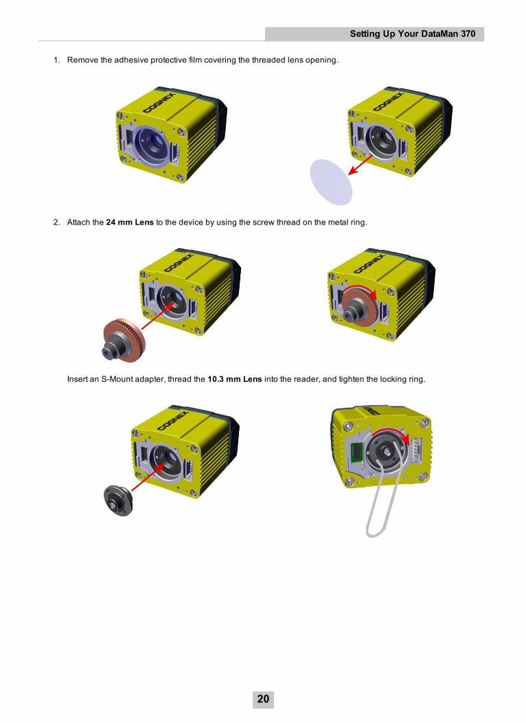
1. Remove the adhesive protective film covering the threaded lens opening.
2. Attach the 24 mm Lens to the device by using the screw thread on the metal ring.
Insert an S-Mount adapter, thread the 10.3 mm Lens into the reader, and tighten the locking ring.
20
Setting Up Your DataMan 370
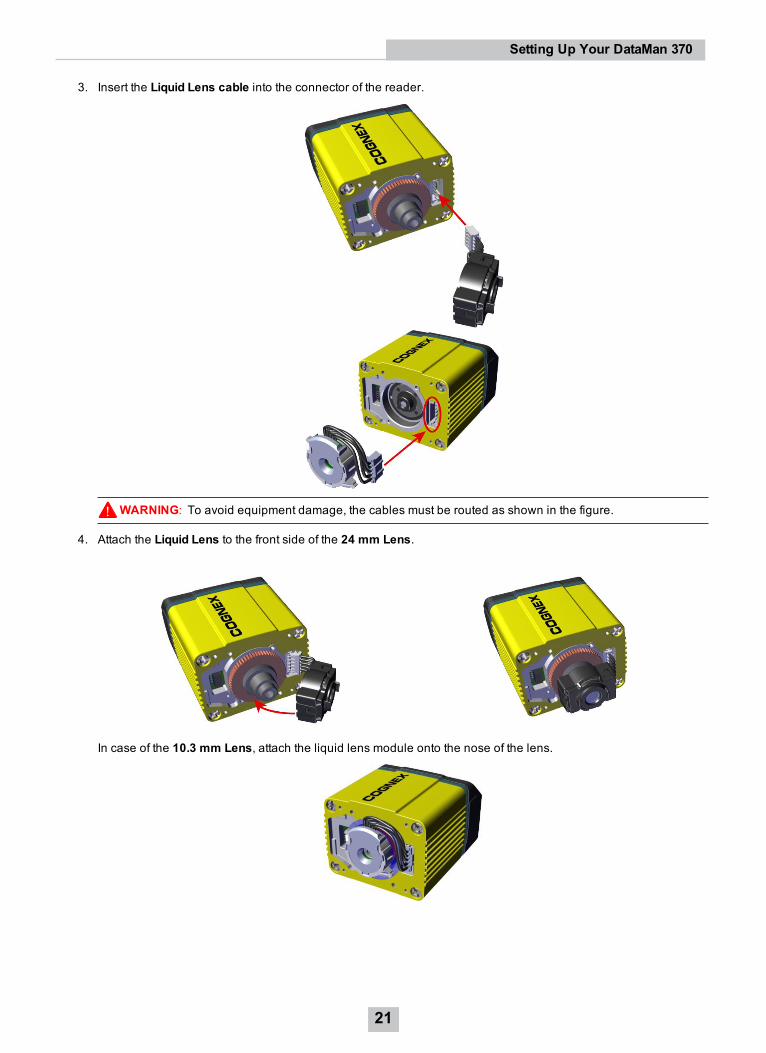
3. Insert the Liquid Lens cable into the connector of the reader.
WARNING: To avoid equipment damage, the cables must be routed as shown in the figure.
4. Attach the Liquid Lens to the front side of the 24 mm Lens.
In case of the 10.3 mm Lens, attach the liquid lens module onto the nose of the lens.
21
Setting Up Your DataMan 370
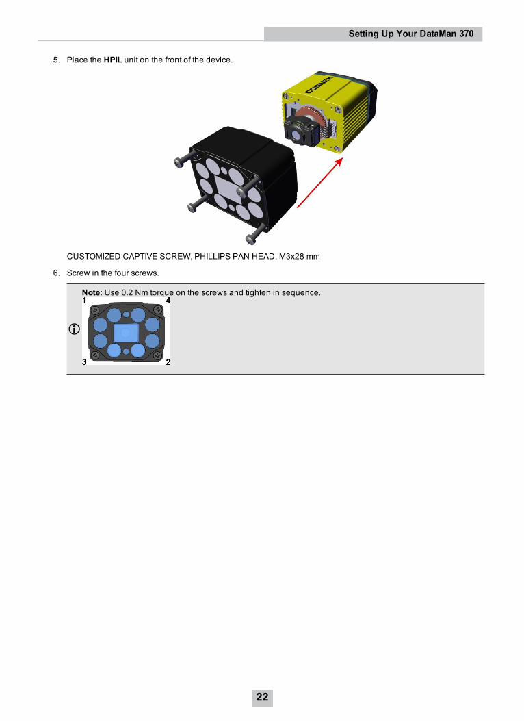
5. Place the HPIL unit on the front of the device.
CUSTOMIZED CAPTIVE SCREW, PHILLIPS PAN HEAD, M3x28 mm
6. Screw in the four screws.
Note: Use 0.2 Nm torque on the screws and tighten in sequence.
22
Setting Up Your DataMan 370
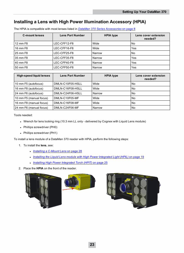
Installing a Lens with High Power Illumination Accessory (HPIA)The HPIA is compatible with most lenses listed in DataMan 370 Series Accessories on page 8
C-mount lenses Lens Part Number HPIA type Lens cover extensionneeded?
12 mm F8 LEC-CFF12-F8 Wide No16 mm F8 LEC-CFF16-F8 Wide Yes25 mm F8 LEC-CFF25-F8 Narrow No35 mm F8 LEC-CFF35-F8 Narrow Yes40 mm F8 LEC-CFF40-F8 Narrow Yes50 mm F8 LEC-CFF50-F8 Narrow Yes
High-speed liquid lenses Lens Part Number HPIA type Lens cover extensionneeded?
10 mm F5 (autofocus) DMLN-C10F05-HSLL Wide No16 mm F8 (autofocus) DMLN-C16F08-HSLL Wide No24 mm F6 (autofocus) DMLN-C24F06-HSLL Narrow No10 mm F5 (manual focus) DMLN-C10F05-MF Wide No16 mm F8 (manual focus) DMLN-C16F08-MF Wide No24 mm F6 (manual focus) DMLN-C24F06-MF Narrow No
Tools needed:
l Wrench for lens locking ring (10.3 mm LL only - delivered by Cognex with Liquid Lens module)
l Phillips screwdriver (PH0)
l Phillips screwdriver (PH1)
To install a lens module of a DataMan 370 reader with HPIA, perform the following steps:
1. To install the lens, see:
l Installing a C-Mount Lens on page 28
l Installing the Liquid Lens module with High Power Integrated Light (HPIL) on page 19
l Installing High Power Integrated Torch (HPIT) on page 25
2. Place the HPIA on the front of the reader.
23
Setting Up Your DataMan 370
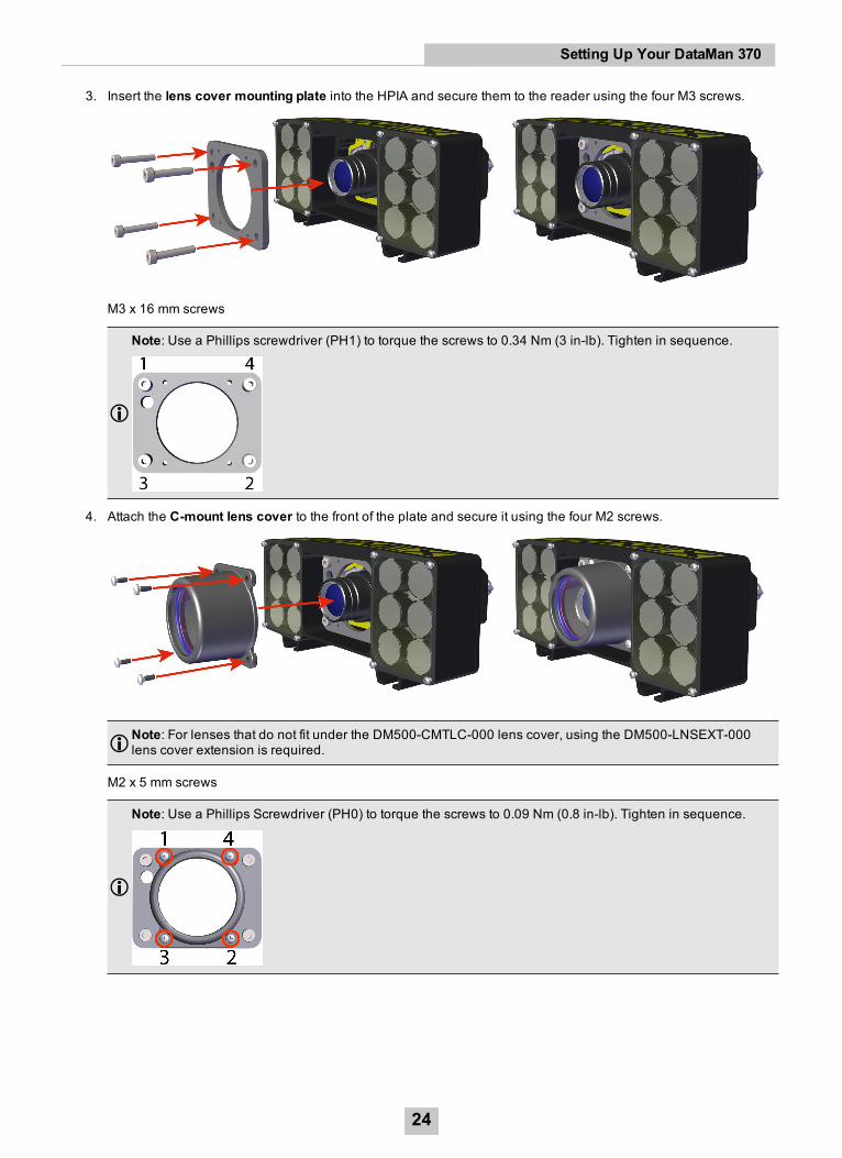
3. Insert the lens cover mounting plate into the HPIA and secure them to the reader using the four M3 screws.
M3 x 16 mm screws
Note: Use a Phillips screwdriver (PH1) to torque the screws to 0.34 Nm (3 in-lb). Tighten in sequence.
4. Attach the C-mount lens cover to the front of the plate and secure it using the four M2 screws.
Note: For lenses that do not fit under the DM500-CMTLC-000 lens cover, using the DM500-LNSEXT-000lens cover extension is required.
M2 x 5 mm screws
Note: Use a Phillips Screwdriver (PH0) to torque the screws to 0.09 Nm (0.8 in-lb). Tighten in sequence.
24
Setting Up Your DataMan 370
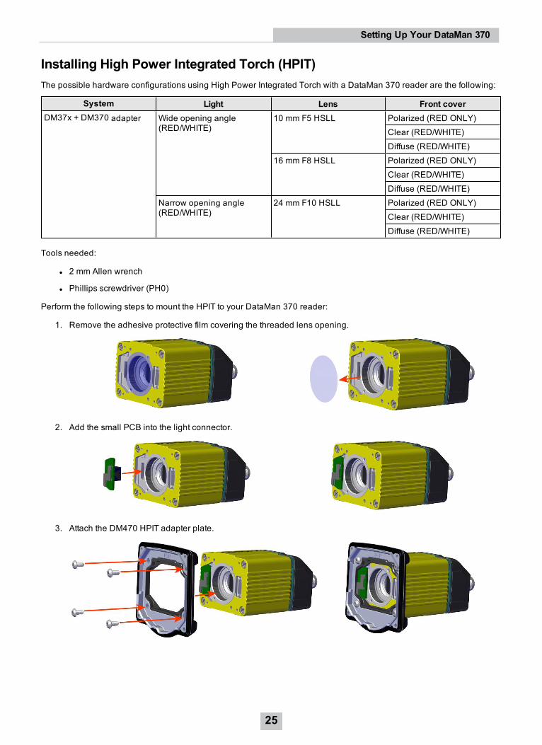
Installing High Power Integrated Torch (HPIT)The possible hardware configurations using High Power Integrated Torch with a DataMan 370 reader are the following:
System Light Lens Front coverDM37x + DM370 adapter Wide opening angle
(RED/WHITE)10 mm F5 HSLL Polarized (RED ONLY)
Clear (RED/WHITE)Diffuse (RED/WHITE)
16 mm F8 HSLL Polarized (RED ONLY)Clear (RED/WHITE)Diffuse (RED/WHITE)
Narrow opening angle(RED/WHITE)
24 mm F10 HSLL Polarized (RED ONLY)Clear (RED/WHITE)Diffuse (RED/WHITE)
Tools needed:
l 2 mm Allen wrench
l Phillips screwdriver (PH0)
Perform the following steps to mount the HPIT to your DataMan 370 reader:
1. Remove the adhesive protective film covering the threaded lens opening.
2. Add the small PCB into the light connector.
3. Attach the DM470 HPIT adapter plate.
25
Setting Up Your DataMan 370
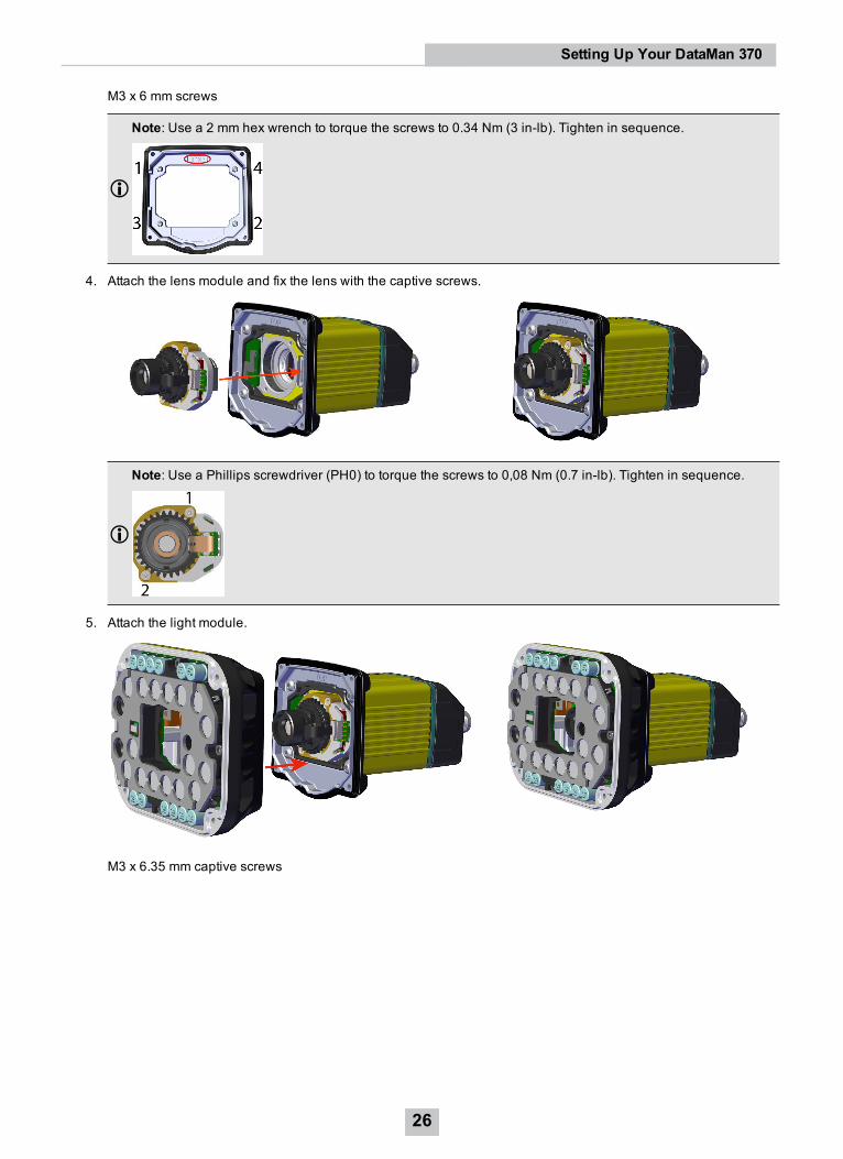
M3 x 6 mm screws
Note: Use a 2 mm hex wrench to torque the screws to 0.34 Nm (3 in-lb). Tighten in sequence.
4. Attach the lens module and fix the lens with the captive screws.
Note: Use a Phillips screwdriver (PH0) to torque the screws to 0,08 Nm (0.7 in-lb). Tighten in sequence.
5. Attach the light module.
M3 x 6.35 mm captive screws
26
Setting Up Your DataMan 370
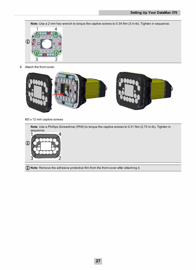
Note: Use a 2 mm hex wrench to torque the captive screws to 0.34 Nm (3 in-lb). Tighten in sequence.
6. Attach the front cover.
M3 x 12 mm captive screws
Note: Use a Phillips Screwdriver (PH0) to torque the captive screws to 0.31 Nm (2.75 in-lb). Tighten insequence.
Note: Remove the adhesive protective film from the front cover after attaching it.
27
Setting Up Your DataMan 370
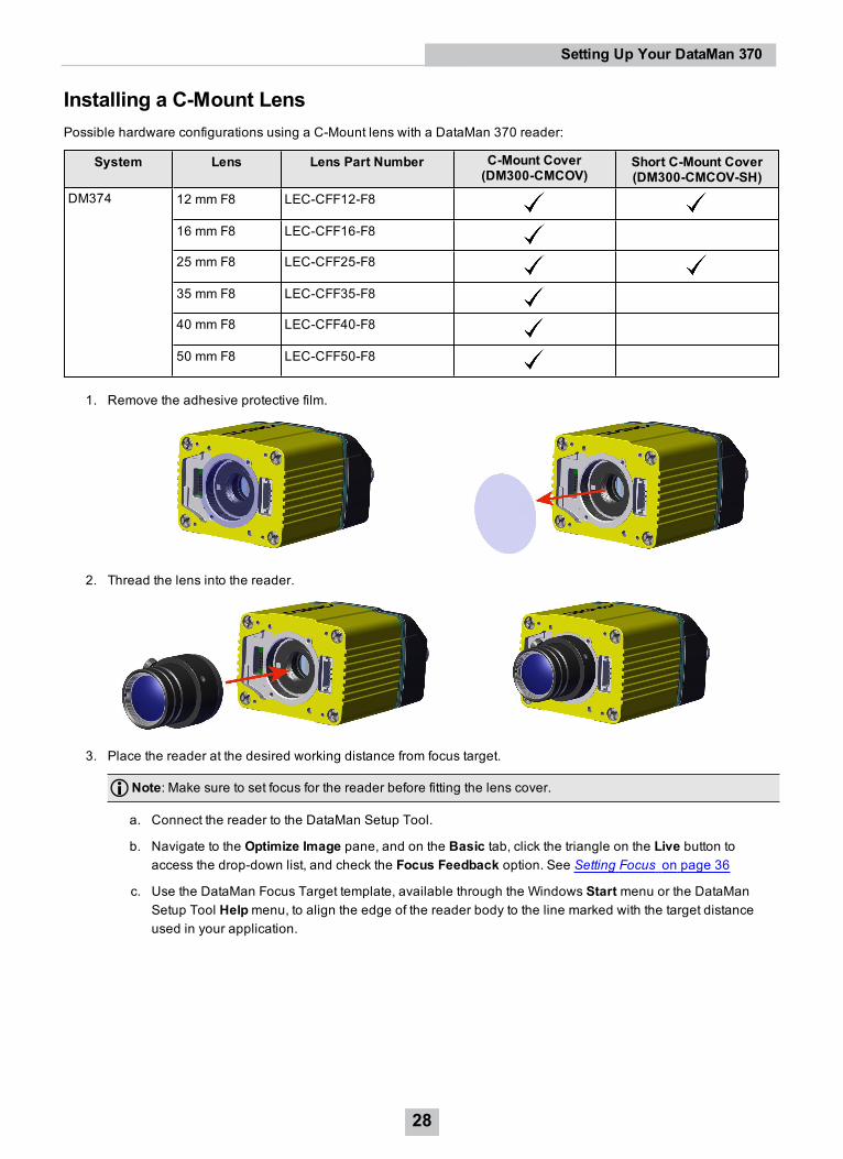
Installing a C-Mount LensPossible hardware configurations using a C-Mount lens with a DataMan 370 reader:
System Lens Lens Part Number C-Mount Cover(DM300-CMCOV)
Short C-Mount Cover(DM300-CMCOV-SH)
DM374 12 mm F8 LEC-CFF12-F8
16 mm F8 LEC-CFF16-F8
25 mm F8 LEC-CFF25-F8
35 mm F8 LEC-CFF35-F8
40 mm F8 LEC-CFF40-F8
50 mm F8 LEC-CFF50-F8
1. Remove the adhesive protective film.
2. Thread the lens into the reader.
3. Place the reader at the desired working distance from focus target.
Note: Make sure to set focus for the reader before fitting the lens cover.
a. Connect the reader to the DataMan Setup Tool.
b. Navigate to the Optimize Image pane, and on the Basic tab, click the triangle on the Live button toaccess the drop-down list, and check the Focus Feedback option. See Setting Focus on page 36
c. Use the DataMan Focus Target template, available through the Windows Start menu or the DataManSetup Tool Helpmenu, to align the edge of the reader body to the line marked with the target distanceused in your application.
28
Setting Up Your DataMan 370
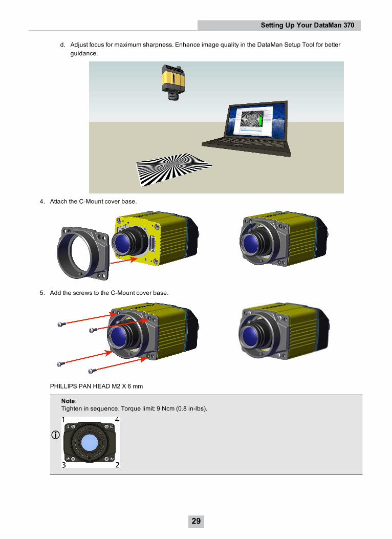
d. Adjust focus for maximum sharpness. Enhance image quality in the DataMan Setup Tool for betterguidance.
4. Attach the C-Mount cover base.
5. Add the screws to the C-Mount cover base.
PHILLIPS PAN HEAD M2 X 6 mm
Note:Tighten in sequence. Torque limit: 9 Ncm (0.8 in-lbs).
29
Setting Up Your DataMan 370
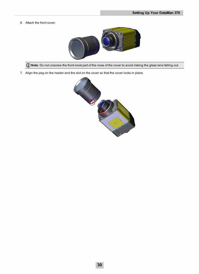
6. Attach the front cover.
Note: Do not unscrew the front-most part of the nose of the cover to avoid risking the glass lens falling out.
7. Align the peg on the reader and the slot on the cover so that the cover locks in place.
30
Setting Up Your DataMan 370
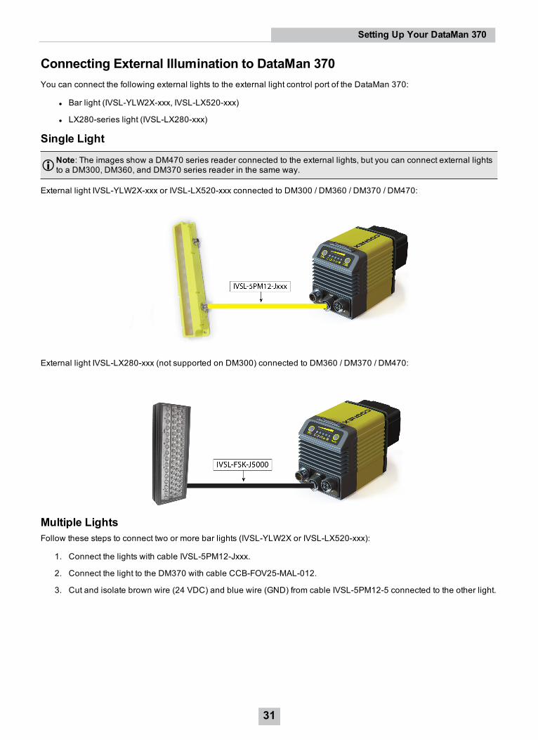
Connecting External Illumination to DataMan 370You can connect the following external lights to the external light control port of the DataMan 370:
l Bar light (IVSL-YLW2X-xxx, IVSL-LX520-xxx)
l LX280-series light (IVSL-LX280-xxx)
Single Light
Note: The images show a DM470 series reader connected to the external lights, but you can connect external lightsto a DM300, DM360, and DM370 series reader in the same way.
External light IVSL-YLW2X-xxx or IVSL-LX520-xxx connected to DM300 / DM360 / DM370 / DM470:
External light IVSL-LX280-xxx (not supported on DM300) connected to DM360 / DM370 / DM470:
Multiple LightsFollow these steps to connect two or more bar lights (IVSL-YLW2X or IVSL-LX520-xxx):
1. Connect the lights with cable IVSL-5PM12-Jxxx.
2. Connect the light to the DM370 with cable CCB-FOV25-MAL-012.
3. Cut and isolate brown wire (24 VDC) and blue wire (GND) from cable IVSL-5PM12-5 connected to the other light.
31
Setting Up Your DataMan 370
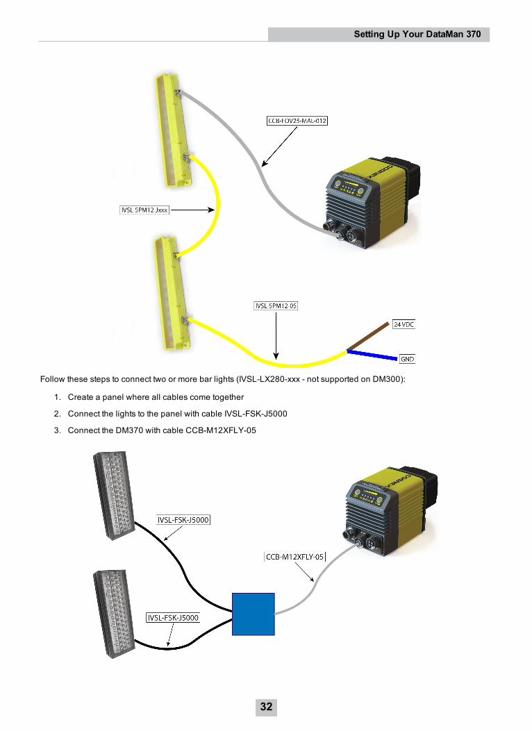
Follow these steps to connect two or more bar lights (IVSL-LX280-xxx - not supported on DM300):
1. Create a panel where all cables come together
2. Connect the lights to the panel with cable IVSL-FSK-J5000
3. Connect the DM370 with cable CCB-M12XFLY-05
32
Setting Up Your DataMan 370
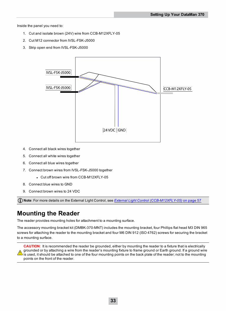
Inside the panel you need to:
1. Cut and isolate brown (24V) wire from CCB-M12XFLY-05
2. Cut M12 connector from IVSL-FSK-J5000
3. Strip open end from IVSL-FSK-J5000
4. Connect all black wires together
5. Connect all white wires together
6. Connect all blue wires together
7. Connect brown wires from IVSL-FSK-J5000 together
l Cut off brown wire from CCB-M12XFLY-05
8. Connect blue wires to GND
9. Connect brown wires to 24 VDC
Note: For more details on the External Light Control, see External Light Control (CCB-M12XFLY-05) on page 57
Mounting the ReaderThe reader provides mounting holes for attachment to a mounting surface.
The accessory mounting bracket kit (DMBK-370-MNT) includes the mounting bracket, four Phillips flat head M3 DIN 965screws for attaching the reader to the mounting bracket and four M6 DIN 912 (ISO 4762) screws for securing the bracketto a mounting surface.
CAUTION: It is recommended the reader be grounded, either by mounting the reader to a fixture that is electricallygrounded or by attaching a wire from the reader’s mounting fixture to frame ground or Earth ground. If a ground wireis used, it should be attached to one of the four mounting points on the back plate of the reader; not to the mountingpoints on the front of the reader.
33
Setting Up Your DataMan 370
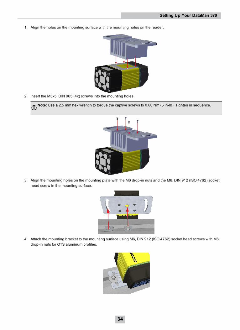
1. Align the holes on the mounting surface with the mounting holes on the reader.
2. Insert the M3x5, DIN 965 (4x) screws into the mounting holes.
Note: Use a 2.5 mm hex wrench to torque the captive screws to 0.60 Nm (5 in-lb). Tighten in sequence.
3. Align the mounting holes on the mounting plate with the M6 drop-in nuts and the M6, DIN 912 (ISO 4762) sockethead screw in the mounting surface.
4. Attach the mounting bracket to the mounting surface using M6, DIN 912 (ISO 4762) socket head screws with M6drop-in nuts for OTS aluminum profiles.
34
Setting Up Your DataMan 370

Mounting the DataMan reader at a slight angle (15°) can reduce reflections and improve performance.
35
Setting Up Your DataMan 370
Setting FocusThere is a range of reading distances available for different code sizes and focus positions. To set focus on your reader,use the following options depending on whether you use a liquid lens or a manual focus lens.
DataMan readers are compatible with multiple different lenses. Each lens has a range of reading distances available fordifferent code sizes and focus positions. Having accurate focus settings is essential to maximize read rates.
To set the focus on your reader, use the following options depending on whether you use a liquid lens or a manual focuslens.
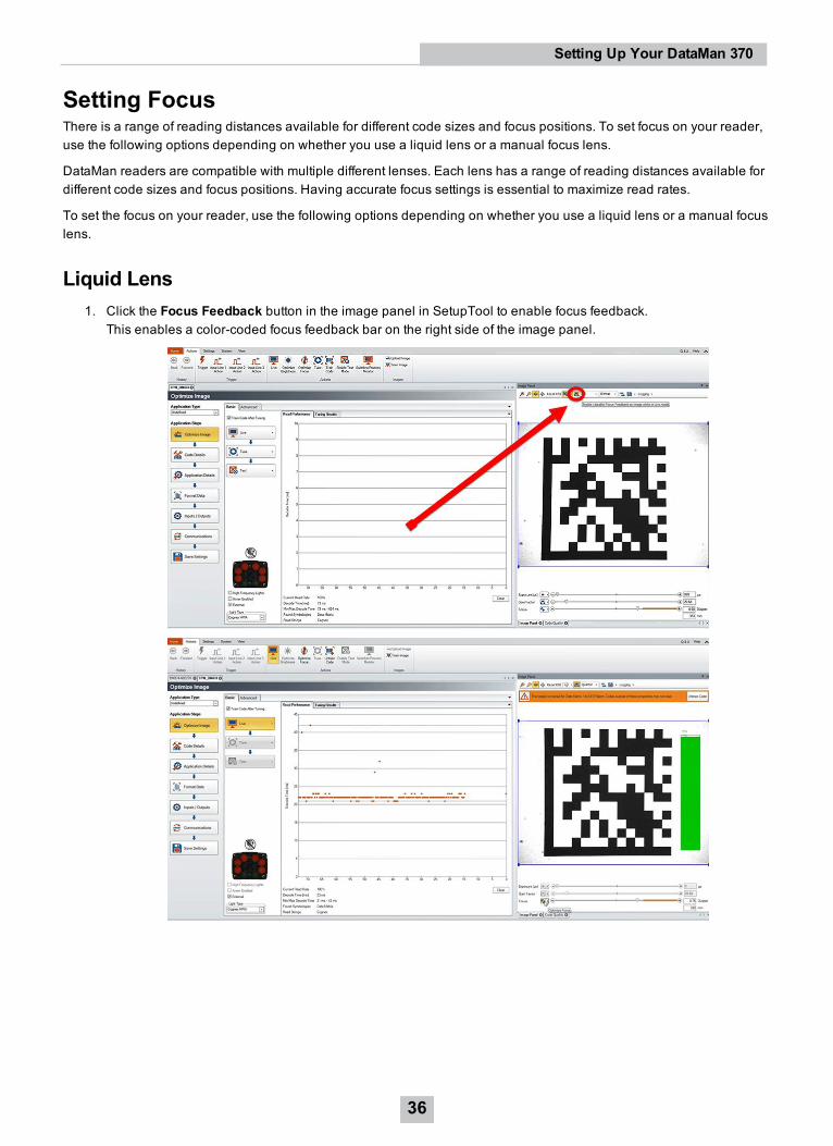
Liquid Lens1. Click the Focus Feedback button in the image panel in SetupTool to enable focus feedback.
This enables a color-coded focus feedback bar on the right side of the image panel.
36
Setting Up Your DataMan 370
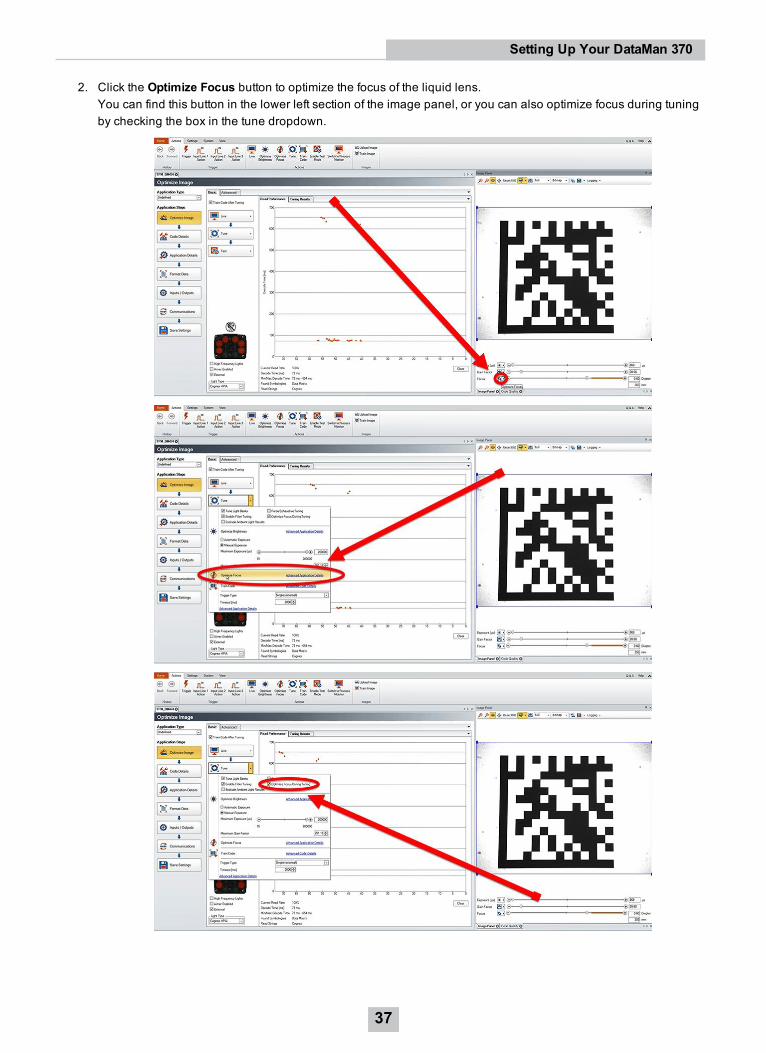
2. Click the Optimize Focus button to optimize the focus of the liquid lens.You can find this button in the lower left section of the image panel, or you can also optimize focus during tuningby checking the box in the tune dropdown.
37
Setting Up Your DataMan 370
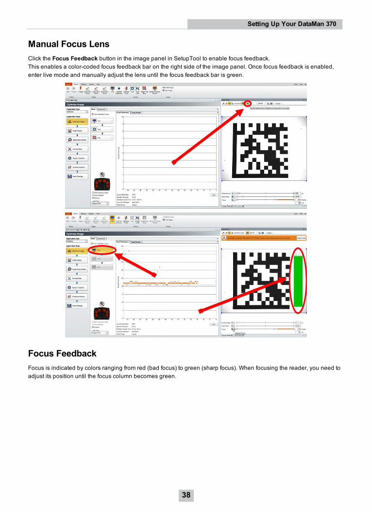
Manual Focus LensClick the Focus Feedback button in the image panel in SetupTool to enable focus feedback.This enables a color-coded focus feedback bar on the right side of the image panel. Once focus feedback is enabled,enter live mode and manually adjust the lens until the focus feedback bar is green.
Focus FeedbackFocus is indicated by colors ranging from red (bad focus) to green (sharp focus). When focusing the reader, you need toadjust its position until the focus column becomes green.
38
Setting Up Your DataMan 370
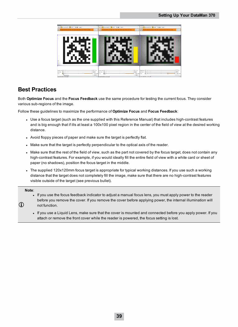
Best PracticesBoth Optimize Focus and the Focus Feedback use the same procedure for testing the current focus. They considervarious sub-regions of the image.
Follow these guidelines to maximize the performance ofOptimize Focus and Focus Feedback:
l Use a focus target (such as the one supplied with this Reference Manual) that includes high-contrast featuresand is big enough that if ills at least a 100x100 pixel region in the center of the field of view at the desired workingdistance.
l Avoid floppy pieces of paper and make sure the target is perfectly flat.
l Make sure that the target is perfectly perpendicular to the optical axis of the reader.
l Make sure that the rest of the field of view, such as the part not covered by the focus target, does not contain anyhigh-contrast features. For example, if you would ideally fill the entire field of view with a white card or sheet ofpaper (no shadows), position the focus target in the middle.
l The supplied 120x120mm focus target is appropriate for typical working distances. If you use such a workingdistance that the target does not completely fill the image, make sure that there are no high-contrast featuresvisible outside of the target (see previous bullet).
Note:l If you use the focus feedback indicator to adjust a manual focus lens, you must apply power to the readerbefore you remove the cover. If you remove the cover before applying power, the internal illumination willnot function.
l If you use a Liquid Lens, make sure that the cover is mounted and connected before you apply power. If youattach or remove the front cover while the reader is powered, the focus setting is lost.
39
Setting Up Your DataMan 370
Field of View and Reading DistancesThe following maps show the field of view of the DataMan 370 series readers. Reading distance values are alsoprovided for 1-D and 2-D example code distances.
For the C-mount (or other non-Cognex) and S-Mount lenses, the focal length of the lens, focus setting, and aperturesetting determine the field of view and reading distance.
Note: Due to tolerances, ranges can vary by +/- 5 % from unit to unit.
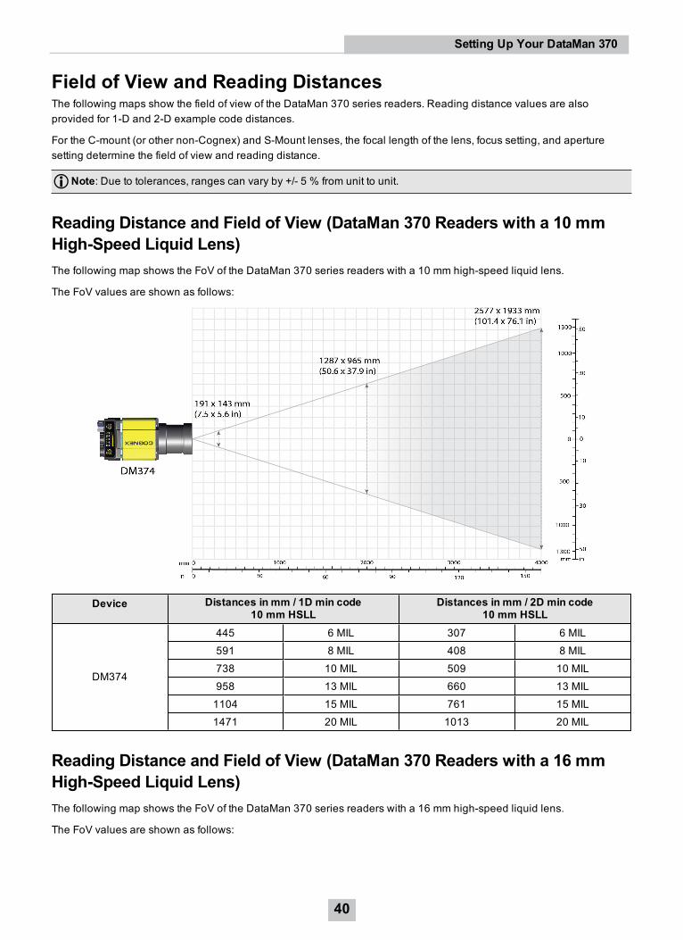
Reading Distance and Field of View (DataMan 370 Readers with a 10 mmHigh-Speed Liquid Lens)The following map shows the FoV of the DataMan 370 series readers with a 10 mm high-speed liquid lens.
The FoV values are shown as follows:
Device Distances in mm / 1D min code10 mm HSLL
Distances in mm / 2D min code10 mm HSLL
DM374
445 6 MIL 307 6 MIL591 8 MIL 408 8 MIL738 10 MIL 509 10 MIL958 13 MIL 660 13 MIL1104 15 MIL 761 15 MIL1471 20 MIL 1013 20 MIL
Reading Distance and Field of View (DataMan 370 Readers with a 16 mmHigh-Speed Liquid Lens)The following map shows the FoV of the DataMan 370 series readers with a 16 mm high-speed liquid lens.
The FoV values are shown as follows:
40
Setting Up Your DataMan 370
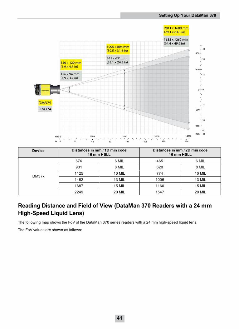
Device Distances in mm / 1D min code16 mm HSLL
Distances in mm / 2D min code16 mm HSLL
DM37x
676 6 MIL 465 6 MIL901 8 MIL 620 8 MIL1125 10 MIL 774 10 MIL1462 13 MIL 1006 13 MIL1687 15 MIL 1160 15 MIL2249 20 MIL 1547 20 MIL
Reading Distance and Field of View (DataMan 370 Readers with a 24 mmHigh-Speed Liquid Lens)The following map shows the FoV of the DataMan 370 series readers with a 24 mm high-speed liquid lens.
The FoV values are shown as follows:
41
Setting Up Your DataMan 370
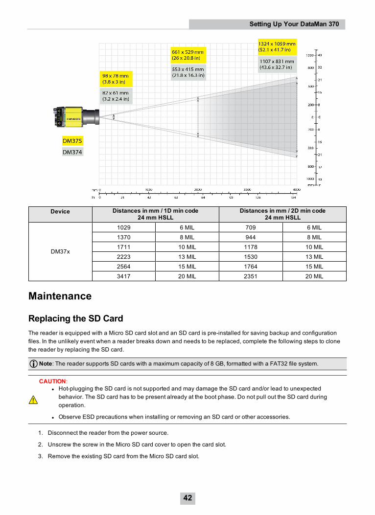
Device Distances in mm / 1D min code24 mm HSLL
Distances in mm / 2D min code24 mm HSLL
DM37x
1029 6 MIL 709 6 MIL1370 8 MIL 944 8 MIL1711 10 MIL 1178 10 MIL2223 13 MIL 1530 13 MIL2564 15 MIL 1764 15 MIL3417 20 MIL 2351 20 MIL
Maintenance
Replacing the SD CardThe reader is equipped with a Micro SD card slot and an SD card is pre-installed for saving backup and configurationfiles. In the unlikely event when a reader breaks down and needs to be replaced, complete the following steps to clonethe reader by replacing the SD card.
Note: The reader supports SD cards with a maximum capacity of 8 GB, formatted with a FAT32 file system.
CAUTION:l Hot-plugging the SD card is not supported and may damage the SD card and/or lead to unexpectedbehavior. The SD card has to be present already at the boot phase. Do not pull out the SD card duringoperation.
l Observe ESD precautions when installing or removing an SD card or other accessories.
1. Disconnect the reader from the power source.
2. Unscrew the screw in the Micro SD card cover to open the card slot.
3. Remove the existing SD card from the Micro SD card slot.
42
Setting Up Your DataMan 370
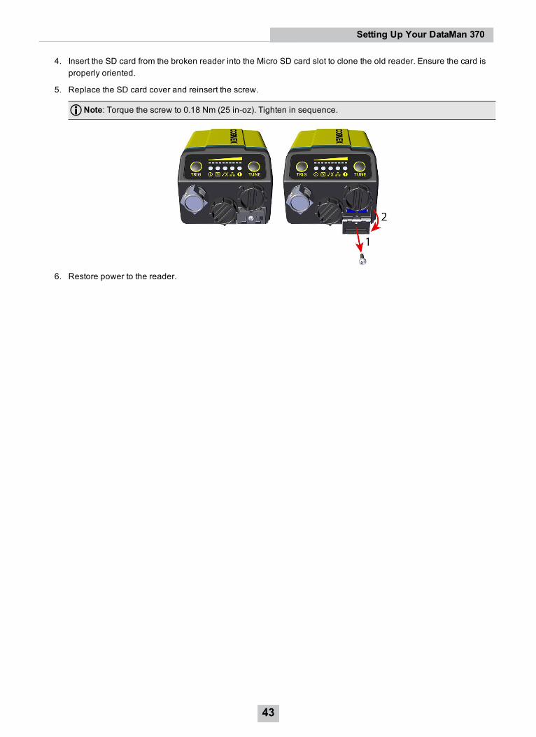
4. Insert the SD card from the broken reader into the Micro SD card slot to clone the old reader. Ensure the card isproperly oriented.
5. Replace the SD card cover and reinsert the screw.
Note: Torque the screw to 0.18 Nm (25 in-oz). Tighten in sequence.
6. Restore power to the reader.
43
Setting Up Your DataMan 370
Additional Information
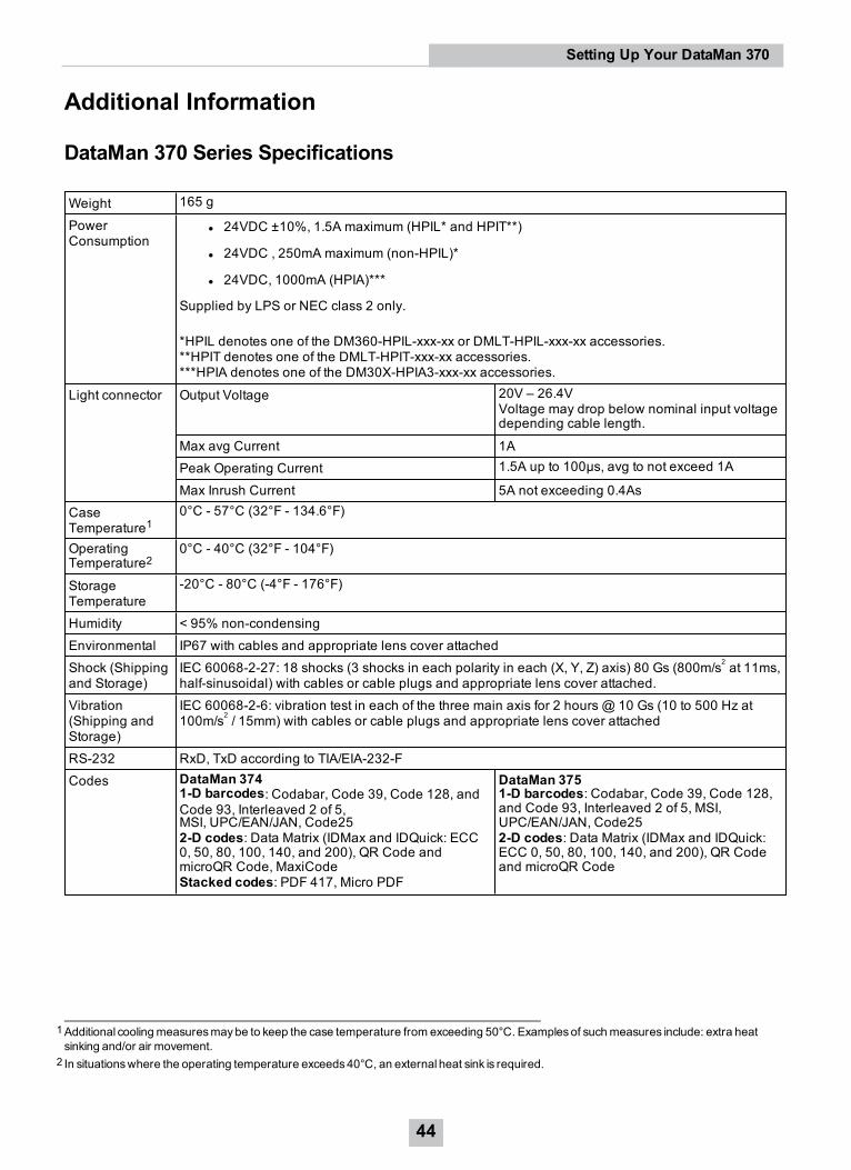
DataMan 370 Series Specifications
Weight 165 g
PowerConsumption
l 24VDC ±10%, 1.5A maximum (HPIL* and HPIT**)
l 24VDC , 250mA maximum (non-HPIL)*
l 24VDC, 1000mA (HPIA)***
Supplied by LPS or NEC class 2 only.
*HPIL denotes one of the DM360-HPIL-xxx-xx or DMLT-HPIL-xxx-xx accessories.**HPIT denotes one of the DMLT-HPIT-xxx-xx accessories.***HPIA denotes one of the DM30X-HPIA3-xxx-xx accessories.
Light connector Output Voltage 20V – 26.4VVoltage may drop below nominal input voltagedepending cable length.
Max avg Current 1APeak Operating Current 1.5A up to 100µs, avg to not exceed 1A
Max Inrush Current 5A not exceeding 0.4AsCaseTemperature1
0°C - 57°C (32°F - 134.6°F)
OperatingTemperature2
0°C - 40°C (32°F - 104°F)
StorageTemperature
-20°C - 80°C (-4°F - 176°F)
Humidity < 95% non-condensingEnvironmental IP67 with cables and appropriate lens cover attachedShock (Shippingand Storage)
IEC 60068-2-27: 18 shocks (3 shocks in each polarity in each (X, Y, Z) axis) 80 Gs (800m/s2 at 11ms,half-sinusoidal) with cables or cable plugs and appropriate lens cover attached.
Vibration(Shipping andStorage)
IEC 60068-2-6: vibration test in each of the three main axis for 2 hours @ 10 Gs (10 to 500 Hz at100m/s2 / 15mm) with cables or cable plugs and appropriate lens cover attached
RS-232 RxD, TxD according to TIA/EIA-232-FCodes DataMan 374
1-D barcodes: Codabar, Code 39, Code 128, andCode 93, Interleaved 2 of 5,MSI, UPC/EAN/JAN, Code252-D codes: Data Matrix (IDMax and IDQuick: ECC0, 50, 80, 100, 140, and 200), QR Code andmicroQR Code, MaxiCodeStacked codes: PDF 417, Micro PDF
DataMan 3751-D barcodes: Codabar, Code 39, Code 128,and Code 93, Interleaved 2 of 5, MSI,UPC/EAN/JAN, Code252-D codes: Data Matrix (IDMax and IDQuick:ECC 0, 50, 80, 100, 140, and 200), QR Codeand microQR Code
1Additional coolingmeasuresmaybe to keep the case temperature from exceeding 50°C. Examplesof suchmeasures include: extra heatsinking and/or air movement.
2 In situationswhere the operating temperature exceeds40°C, an external heat sink is required.
44
Setting Up Your DataMan 370
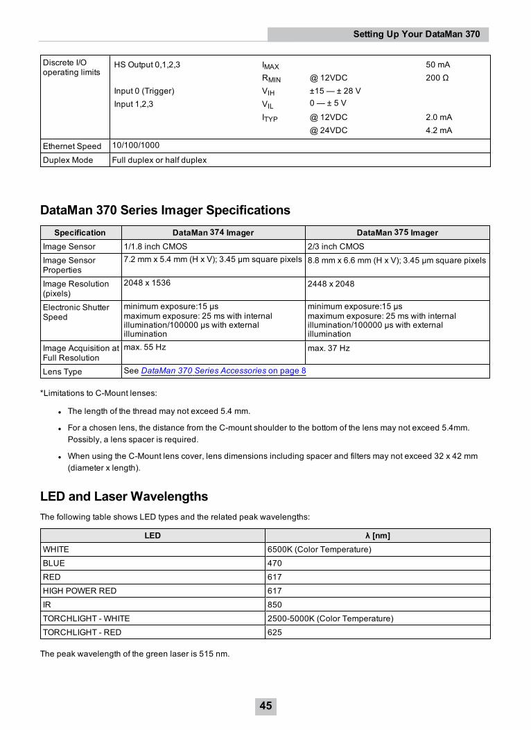
Discrete I/Ooperating limits
HS Output 0,1,2,3 IMAX 50 mARMIN @12VDC 200 Ω
Input 0 (Trigger) VIH ±15 — ± 28 VInput 1,2,3 VIL 0 — ± 5 V
ITYP @12VDC 2.0 mA@ 24VDC 4.2 mA
Ethernet Speed 10/100/1000
Duplex Mode Full duplex or half duplex
DataMan 370 Series Imager SpecificationsSpecification DataMan 374 Imager DataMan 375 Imager
Image Sensor 1/1.8 inch CMOS 2/3 inch CMOSImage SensorProperties
7.2 mm x 5.4 mm (H x V); 3.45 µm square pixels 8.8 mm x 6.6 mm (H x V); 3.45 µm square pixels
Image Resolution(pixels)
2048 x 1536 2448 x 2048
Electronic ShutterSpeed
minimum exposure:15 µsmaximum exposure: 25 ms with internalillumination/100000 µs with externalillumination
minimum exposure:15 µsmaximum exposure: 25 ms with internalillumination/100000 µs with externalillumination
Image Acquisition atFull Resolution
max. 55 Hz max. 37 Hz
Lens Type See DataMan 370 Series Accessories on page 8
*Limitations to C-Mount lenses:
l The length of the thread may not exceed 5.4 mm.
l For a chosen lens, the distance from the C-mount shoulder to the bottom of the lens may not exceed 5.4mm.Possibly, a lens spacer is required.
l When using the C-Mount lens cover, lens dimensions including spacer and filters may not exceed 32 x 42 mm(diameter x length).
LED and Laser WavelengthsThe following table shows LED types and the related peak wavelengths:
LED λ [nm]WHITE 6500K (Color Temperature)BLUE 470RED 617HIGH POWER RED 617IR 850TORCHLIGHT - WHITE 2500-5000K (Color Temperature)TORCHLIGHT - RED 625
The peak wavelength of the green laser is 515 nm.
45
Setting Up Your DataMan 370
Using Your DataMan 370This section provides information on the installation process of the DataMan Setup Tool, troubleshooting Ethernetconnection issues, tuning, image filtering, as well as reader training and package detection.
Reading your First CodeFollow the steps below to install and connect your reader to the DataMan Setup Tool:
1. Check the DataMan Release Notes for a full list of system requirements found at C:\Program Files(x86)\Cognex\DataMan\DataMan Software v6.1.6\Documentation\English.
2. Download the latest version of the DataMan Setup Tool from http://www.cognex.com/support/dataman and followthe on-screen steps.
3. Connect the DataMan 370 Series reader to your PC using the x-coded Ethernet cable or the RS-232 cable andpower the reader using the breakout cable. See Connections, Optics, and Lighting on page 57 for breakout cablepinouts.*
Note: *See appendix for use with IO Box.
46
Using Your DataMan 370
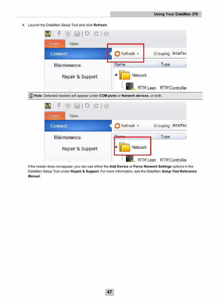
4. Launch the DataMan Setup Tool and click Refresh.
Note: Detected readers will appear under COM ports or Network devices, or both.
If the reader does not appear, you can use either the Add Device or Force Network Settings options in theDataMan Setup Tool under Repair & Support. For more information, see the DataMan Setup Tool ReferenceManual.
47
Using Your DataMan 370
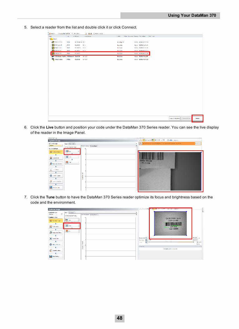
5. Select a reader from the list and double click it or click Connect.
6. Click the Live button and position your code under the DataMan 370 Series reader. You can see the live displayof the reader in the Image Panel.
7. Click the Tune button to have the DataMan 370 Series reader optimize its focus and brightness based on thecode and the environment.
48
Using Your DataMan 370
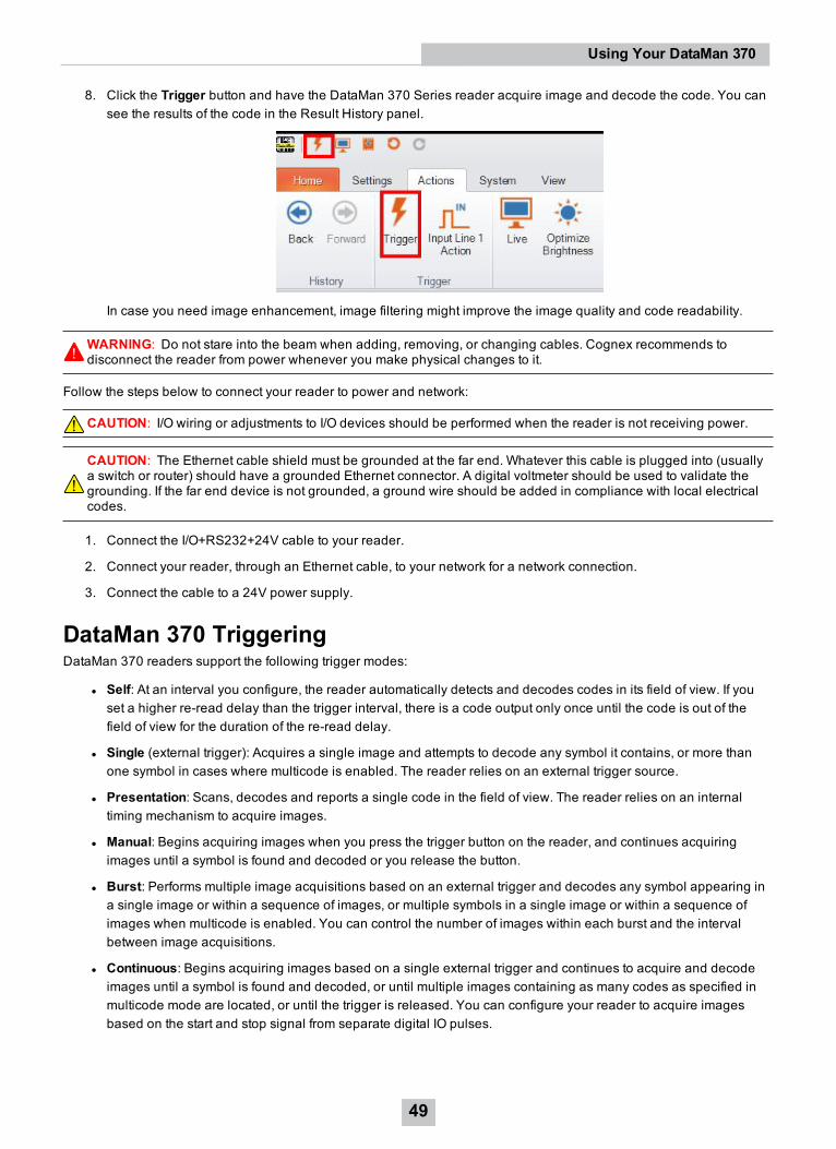
8. Click the Trigger button and have the DataMan 370 Series reader acquire image and decode the code. You cansee the results of the code in the Result History panel.
In case you need image enhancement, image filtering might improve the image quality and code readability.
WARNING: Do not stare into the beam when adding, removing, or changing cables. Cognex recommends todisconnect the reader from power whenever you make physical changes to it.
Follow the steps below to connect your reader to power and network:
CAUTION: I/O wiring or adjustments to I/O devices should be performed when the reader is not receiving power.
CAUTION: The Ethernet cable shield must be grounded at the far end. Whatever this cable is plugged into (usuallya switch or router) should have a grounded Ethernet connector. A digital voltmeter should be used to validate thegrounding. If the far end device is not grounded, a ground wire should be added in compliance with local electricalcodes.
1. Connect the I/O+RS232+24V cable to your reader.
2. Connect your reader, through an Ethernet cable, to your network for a network connection.
3. Connect the cable to a 24V power supply.
DataMan 370 TriggeringDataMan 370 readers support the following trigger modes:
l Self: At an interval you configure, the reader automatically detects and decodes codes in its field of view. If youset a higher re-read delay than the trigger interval, there is a code output only once until the code is out of thefield of view for the duration of the re-read delay.
l Single (external trigger): Acquires a single image and attempts to decode any symbol it contains, or more thanone symbol in cases where multicode is enabled. The reader relies on an external trigger source.
l Presentation: Scans, decodes and reports a single code in the field of view. The reader relies on an internaltiming mechanism to acquire images.
l Manual: Begins acquiring images when you press the trigger button on the reader, and continues acquiringimages until a symbol is found and decoded or you release the button.
l Burst: Performs multiple image acquisitions based on an external trigger and decodes any symbol appearing ina single image or within a sequence of images, or multiple symbols in a single image or within a sequence ofimages when multicode is enabled. You can control the number of images within each burst and the intervalbetween image acquisitions.
l Continuous: Begins acquiring images based on a single external trigger and continues to acquire and decodeimages until a symbol is found and decoded, or until multiple images containing as many codes as specified inmulticode mode are located, or until the trigger is released. You can configure your reader to acquire imagesbased on the start and stop signal from separate digital IO pulses.
49
Using Your DataMan 370
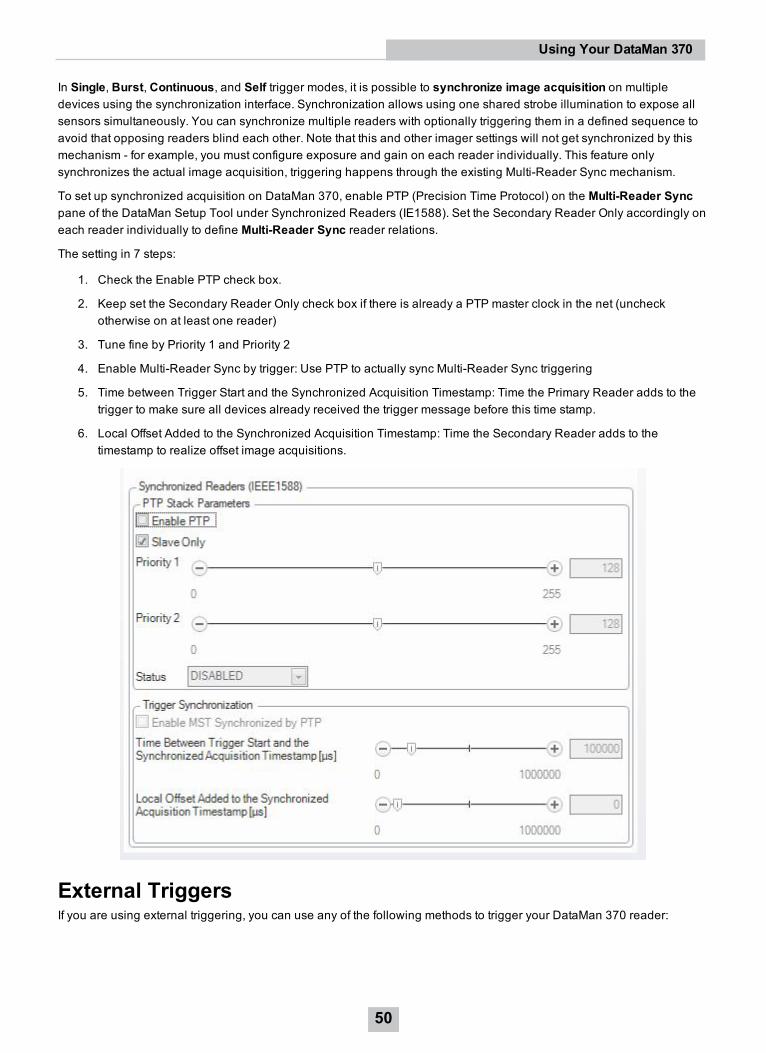
In Single, Burst, Continuous, and Self trigger modes, it is possible to synchronize image acquisition on multipledevices using the synchronization interface. Synchronization allows using one shared strobe illumination to expose allsensors simultaneously. You can synchronize multiple readers with optionally triggering them in a defined sequence toavoid that opposing readers blind each other. Note that this and other imager settings will not get synchronized by thismechanism - for example, you must configure exposure and gain on each reader individually. This feature onlysynchronizes the actual image acquisition, triggering happens through the existing Multi-Reader Sync mechanism.
To set up synchronized acquisition on DataMan 370, enable PTP (Precision Time Protocol) on the Multi-Reader Syncpane of the DataMan Setup Tool under Synchronized Readers (IE1588). Set the Secondary Reader Only accordingly oneach reader individually to define Multi-Reader Sync reader relations.
The setting in 7 steps:
1. Check the Enable PTP check box.
2. Keep set the Secondary Reader Only check box if there is already a PTP master clock in the net (uncheckotherwise on at least one reader)
3. Tune fine by Priority 1 and Priority 2
4. Enable Multi-Reader Sync by trigger: Use PTP to actually sync Multi-Reader Sync triggering
5. Time between Trigger Start and the Synchronized Acquisition Timestamp: Time the Primary Reader adds to thetrigger to make sure all devices already received the trigger message before this time stamp.
6. Local Offset Added to the Synchronized Acquisition Timestamp: Time the Secondary Reader adds to thetimestamp to realize offset image acquisitions.
External TriggersIf you are using external triggering, you can use any of the following methods to trigger your DataMan 370 reader:
50
Using Your DataMan 370
l Press the trigger button on the reader.
l Send a pulse on the I/O cable:
l Trigger + (orange or red)
l Trigger - (black)
l Send a serial trigger command over the RS-232 connection or Ethernet connection.
l Press <CTRL-T> on the keyboard while the DataMan Setup Tool has the input focus.
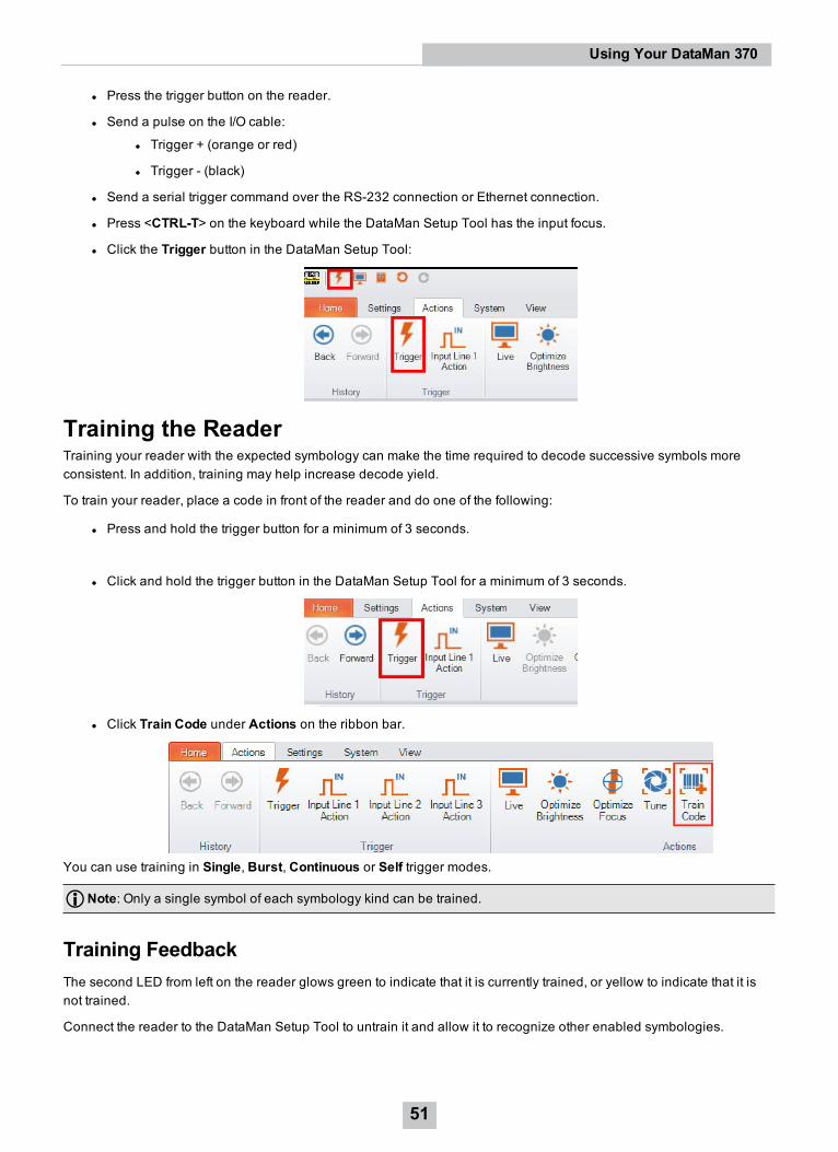
l Click the Trigger button in the DataMan Setup Tool:
Training the ReaderTraining your reader with the expected symbology can make the time required to decode successive symbols moreconsistent. In addition, training may help increase decode yield.
To train your reader, place a code in front of the reader and do one of the following:
l Press and hold the trigger button for a minimum of 3 seconds.
l Click and hold the trigger button in the DataMan Setup Tool for a minimum of 3 seconds.
l Click Train Code under Actions on the ribbon bar.
You can use training in Single, Burst, Continuous or Self trigger modes.
Note: Only a single symbol of each symbology kind can be trained.
Training FeedbackThe second LED from left on the reader glows green to indicate that it is currently trained, or yellow to indicate that it isnot trained.
Connect the reader to the DataMan Setup Tool to untrain it and allow it to recognize other enabled symbologies.
51
Using Your DataMan 370
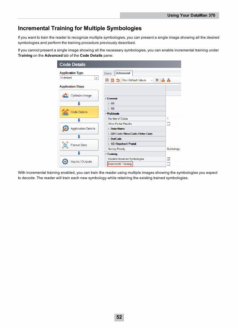
Incremental Training for Multiple SymbologiesIf you want to train the reader to recognize multiple symbologies, you can present a single image showing all the desiredsymbologies and perform the training procedure previously described.
If you cannot present a single image showing all the necessary symbologies, you can enable incremental training underTraining on the Advanced tab of the Code Details pane:
With incremental training enabled, you can train the reader using multiple images showing the symbologies you expectto decode. The reader will train each new symbology while retaining the existing trained symbologies.
52
Using Your DataMan 370
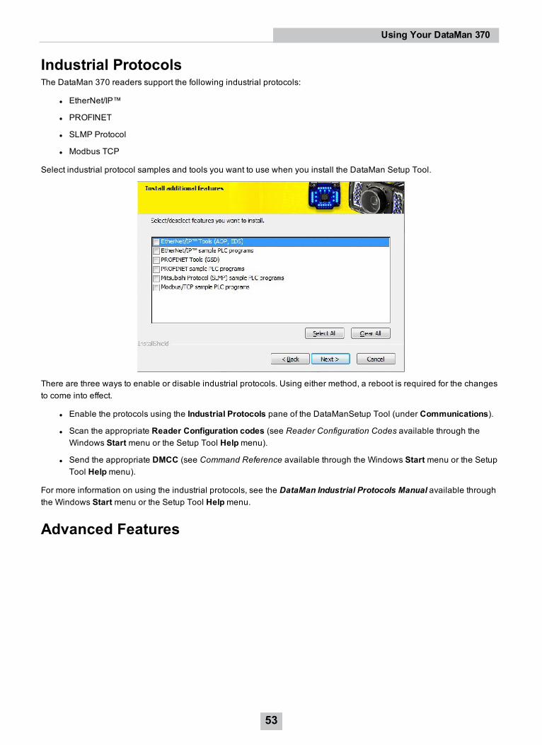
Industrial ProtocolsThe DataMan 370 readers support the following industrial protocols:
l EtherNet/IP™
l PROFINET
l SLMP Protocol
l Modbus TCP
Select industrial protocol samples and tools you want to use when you install the DataMan Setup Tool.
There are three ways to enable or disable industrial protocols. Using either method, a reboot is required for the changesto come into effect.
l Enable the protocols using the Industrial Protocols pane of the DataManSetup Tool (under Communications).
l Scan the appropriate Reader Configuration codes (see Reader Configuration Codes available through theWindows Start menu or the Setup Tool Helpmenu).
l Send the appropriate DMCC (see Command Reference available through the Windows Start menu or the SetupTool Helpmenu).
For more information on using the industrial protocols, see the DataMan Industrial Protocols Manual available throughthe Windows Start menu or the Setup Tool Helpmenu.
Advanced Features
53
Using Your DataMan 370
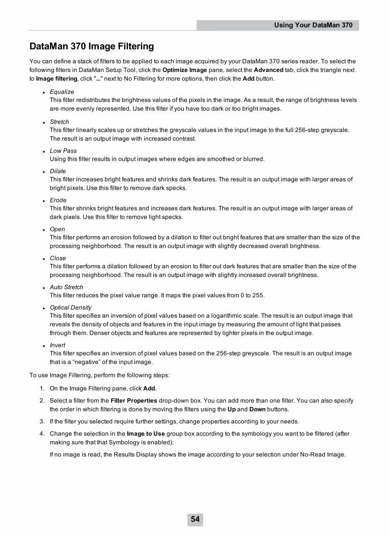
DataMan 370 Image FilteringYou can define a stack of filters to be applied to each image acquired by your DataMan 370 series reader. To select thefollowing filters in DataMan Setup Tool, click the Optimize Image pane, select the Advanced tab, click the triangle nextto Image filtering, click "..." next to No Filtering for more options, then click the Add button.
l EqualizeThis filter redistributes the brightness values of the pixels in the image. As a result, the range of brightness levelsare more evenly represented. Use this filter if you have too dark or too bright images.
l StretchThis filter linearly scales up or stretches the greyscale values in the input image to the full 256-step greyscale.The result is an output image with increased contrast.
l Low PassUsing this filter results in output images where edges are smoothed or blurred.
l DilateThis filter increases bright features and shrinks dark features. The result is an output image with larger areas ofbright pixels. Use this filter to remove dark specks.
l ErodeThis filter shrinks bright features and increases dark features. The result is an output image with larger areas ofdark pixels. Use this filter to remove light specks.
l OpenThis filter performs an erosion followed by a dilation to filter out bright features that are smaller than the size of theprocessing neighborhood. The result is an output image with slightly decreased overall brightness.
l CloseThis filter performs a dilation followed by an erosion to filter out dark features that are smaller than the size of theprocessing neighborhood. The result is an output image with slightly increased overall brightness.
l Auto StretchThis filter reduces the pixel value range. It maps the pixel values from 0 to 255.
l Optical DensityThis filter specifies an inversion of pixel values based on a logarithmic scale. The result is an output image thatreveals the density of objects and features in the input image by measuring the amount of light that passesthrough them. Denser objects and features are represented by lighter pixels in the output image.
l InvertThis filter specifies an inversion of pixel values based on the 256-step greyscale. The result is an output imagethat is a “negative” of the input image.
To use Image Filtering, perform the following steps:
1. On the Image Filtering pane, click Add.
2. Select a filter from the Filter Properties drop-down box. You can add more than one filter. You can also specifythe order in which filtering is done by moving the filters using the Up and Down buttons.
3. If the filter you selected require further settings, change properties according to your needs.
4. Change the selection in the Image to Use group box according to the symbology you want to be filtered (aftermaking sure that that Symbology is enabled):
If no image is read, the Results Display shows the image according to your selection under No-Read Image.
54
Using Your DataMan 370
5. Go to the Displayed Image Settings pane and change the Images to Use according to what you want to see onLive Display: the original or the filtered image.
6. You can compare the original and filtered results on the Results Display if you choose the images from the ReadResult History.The example images were taken using the Equalize filter.
Package Detection SupportYou can connect your package detection sensor to one of the digital inputs of your DataMan reader. When the readerreceives a signal that a package is detected, images that the reader collected are not discarded at the end of the trigger.This way you can make sure that there was a package there, only the code was not readable. Looking at the No Readimages will help you find out why there were no decode results.
Package detection is only supported with Continuous trigger mode.
To make sure that the No Read images are collected, perform the following:
1. Connect your package detection device to one of the Inputs of your reader.
2. On the Inputs/Outputs pane, check Allow Buffered No-Read Images on the input you connected your reader to.
3. On the Inputs/Outputs pane, click Buffering and Transfer, and in the Image Buffering pane, changeWhatResults to Buffer under Buffering Settings to All, or No Read.
l In the case of All, good reads are also saved together with No Reads.
l In the case of No Read, the image is buffered if the reader fails to read.
For more information, see the DataMan Fixed-Mount Readers Reference, available through the Windows Start menuor the DataMan Setup Tool Helpmenu.
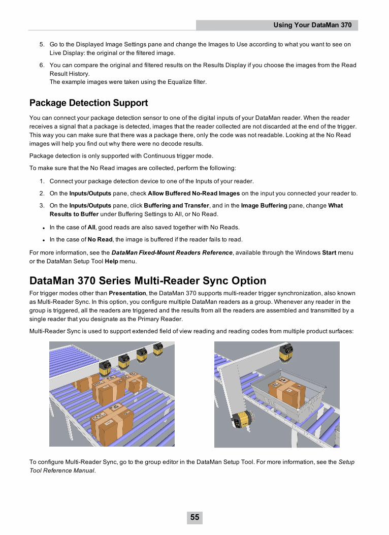
DataMan 370 Series Multi-Reader Sync OptionFor trigger modes other than Presentation, the DataMan 370 supports multi-reader trigger synchronization, also knownas Multi-Reader Sync. In this option, you configure multiple DataMan readers as a group. Whenever any reader in thegroup is triggered, all the readers are triggered and the results from all the readers are assembled and transmitted by asingle reader that you designate as the Primary Reader.
Multi-Reader Sync is used to support extended field of view reading and reading codes from multiple product surfaces:
To configure Multi-Reader Sync, go to the group editor in the DataMan Setup Tool. For more information, see the SetupTool Reference Manual.
55
Using Your DataMan 370
In Single, Burst, Continuous, and Self trigger modes, it is possible to synchronize image acquisition on multipledevices using the synchronization interface. Synchronization allows using one shared strobe illumination to expose allsensors simultaneously. You can synchronize multiple readers, with optionally triggering them in a defined sequence toavoid that opposing readers blind each other. Note that this and other imager settings will not get synchronized by thismechanism - for example, you must configure exposure and gain on each reader individually. This feature onlysynchronizes the actual image acquisition. Triggering happens through the existing Multi-Reader Sync mechanism.
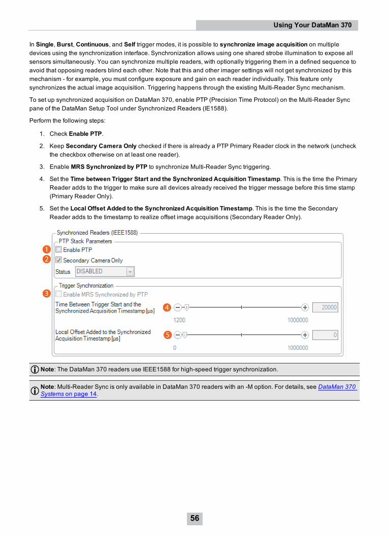
To set up synchronized acquisition on DataMan 370, enable PTP (Precision Time Protocol) on the Multi-Reader Syncpane of the DataMan Setup Tool under Synchronized Readers (IE1588).
Perform the following steps:
1. Check Enable PTP.
2. Keep Secondary Camera Only checked if there is already a PTP Primary Reader clock in the network (uncheckthe checkbox otherwise on at least one reader).
3. Enable MRS Synchronized by PTP to synchronize Multi-Reader Sync triggering.
4. Set the Time between Trigger Start and the Synchronized Acquisition Timestamp. This is the time the PrimaryReader adds to the trigger to make sure all devices already received the trigger message before this time stamp(Primary Reader Only).
5. Set the Local Offset Added to the Synchronized Acquisition Timestamp. This is the time the SecondaryReader adds to the timestamp to realize offset image acquisitions (Secondary Reader Only).
Note: The DataMan 370 readers use IEEE1588 for high-speed trigger synchronization.
Note: Multi-Reader Sync is only available in DataMan 370 readers with an -M option. For details, see DataMan 370Systems on page 14.
56
Using Your DataMan 370
Connections, Optics, and LightingThis section contains descriptions about the external light control, I/O Cables, high-speed outputs, high-speed outputwiring, Ethernet M12 to RJ45 cable, and acquisition trigger.
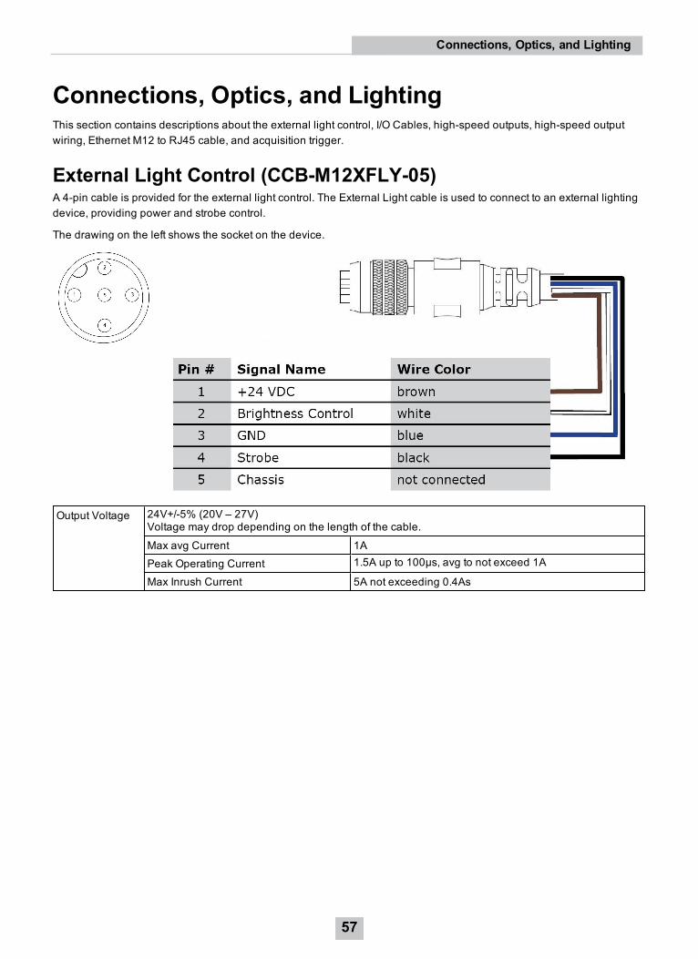
External Light Control (CCB-M12XFLY-05)A 4-pin cable is provided for the external light control. The External Light cable is used to connect to an external lightingdevice, providing power and strobe control.
The drawing on the left shows the socket on the device.
Output Voltage 24V+/-5% (20V – 27V)Voltage may drop depending on the length of the cable.
Max avg Current 1APeak Operating Current 1.5A up to 100µs, avg to not exceed 1A
Max Inrush Current 5A not exceeding 0.4As
57
Connections, Optics, and Lighting
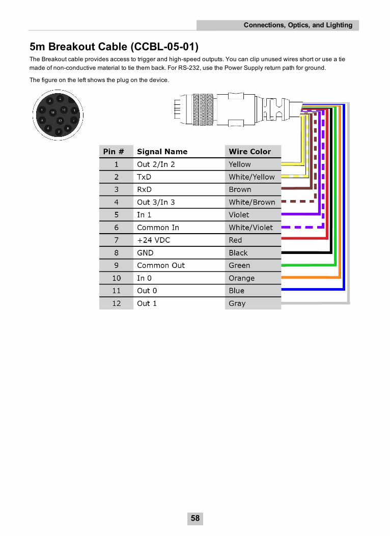
5m Breakout Cable (CCBL-05-01)The Breakout cable provides access to trigger and high-speed outputs. You can clip unused wires short or use a tiemade of non-conductive material to tie them back. For RS-232, use the Power Supply return path for ground.
The figure on the left shows the plug on the device.
58
Connections, Optics, and Lighting
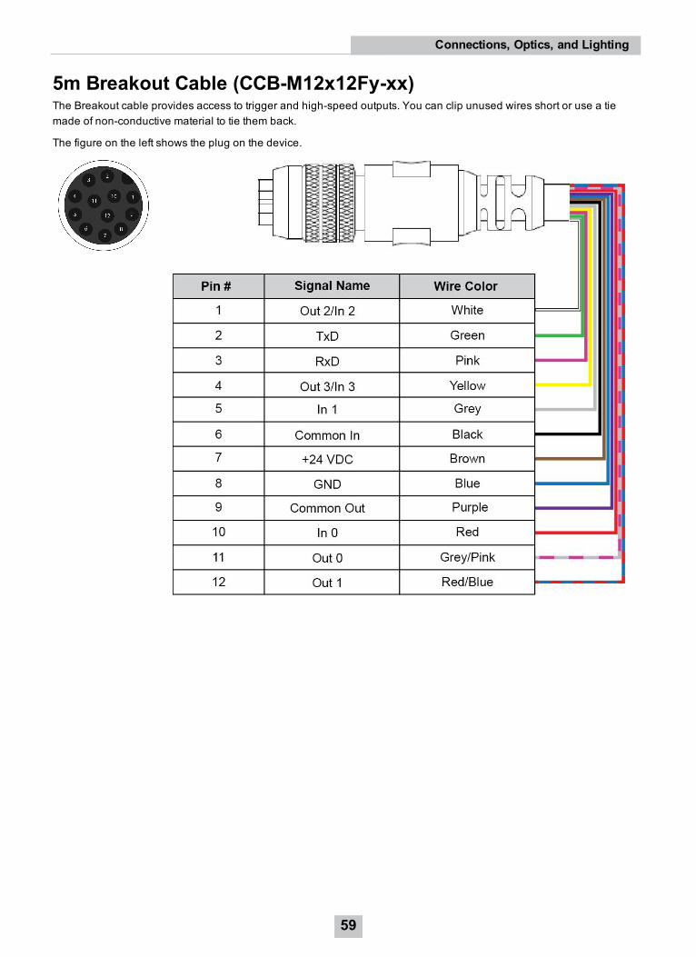
5m Breakout Cable (CCB-M12x12Fy-xx)The Breakout cable provides access to trigger and high-speed outputs. You can clip unused wires short or use a tiemade of non-conductive material to tie them back.
The figure on the left shows the plug on the device.
59
Connections, Optics, and Lighting
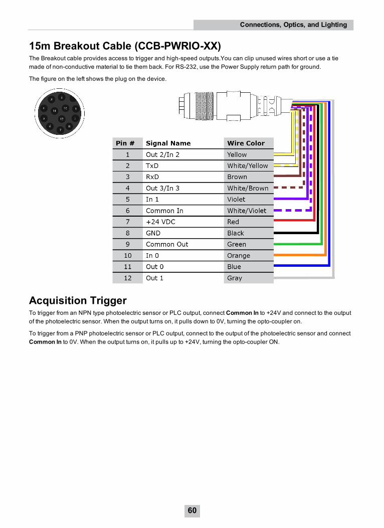
15m Breakout Cable (CCB-PWRIO-XX)The Breakout cable provides access to trigger and high-speed outputs.You can clip unused wires short or use a tiemade of non-conductive material to tie them back. For RS-232, use the Power Supply return path for ground.
The figure on the left shows the plug on the device.
Acquisition TriggerTo trigger from an NPN type photoelectric sensor or PLC output, connect Common In to +24V and connect to the outputof the photoelectric sensor. When the output turns on, it pulls down to 0V, turning the opto-coupler on.
To trigger from a PNP photoelectric sensor or PLC output, connect to the output of the photoelectric sensor and connectCommon In to 0V. When the output turns on, it pulls up to +24V, turning the opto-coupler ON.
60
Connections, Optics, and Lighting
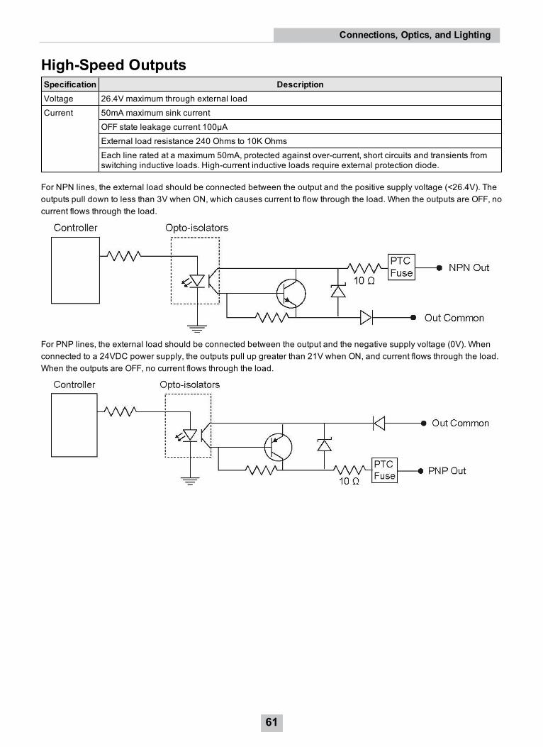
High-Speed OutputsSpecification DescriptionVoltage 26.4V maximum through external loadCurrent 50mA maximum sink current
OFF state leakage current 100µAExternal load resistance 240 Ohms to 10K OhmsEach line rated at a maximum 50mA, protected against over-current, short circuits and transients fromswitching inductive loads. High-current inductive loads require external protection diode.
For NPN lines, the external load should be connected between the output and the positive supply voltage (<26.4V). Theoutputs pull down to less than 3V when ON, which causes current to flow through the load. When the outputs are OFF, nocurrent flows through the load.
For PNP lines, the external load should be connected between the output and the negative supply voltage (0V). Whenconnected to a 24VDC power supply, the outputs pull up greater than 21V when ON, and current flows through the load.When the outputs are OFF, no current flows through the load.
61
Connections, Optics, and Lighting
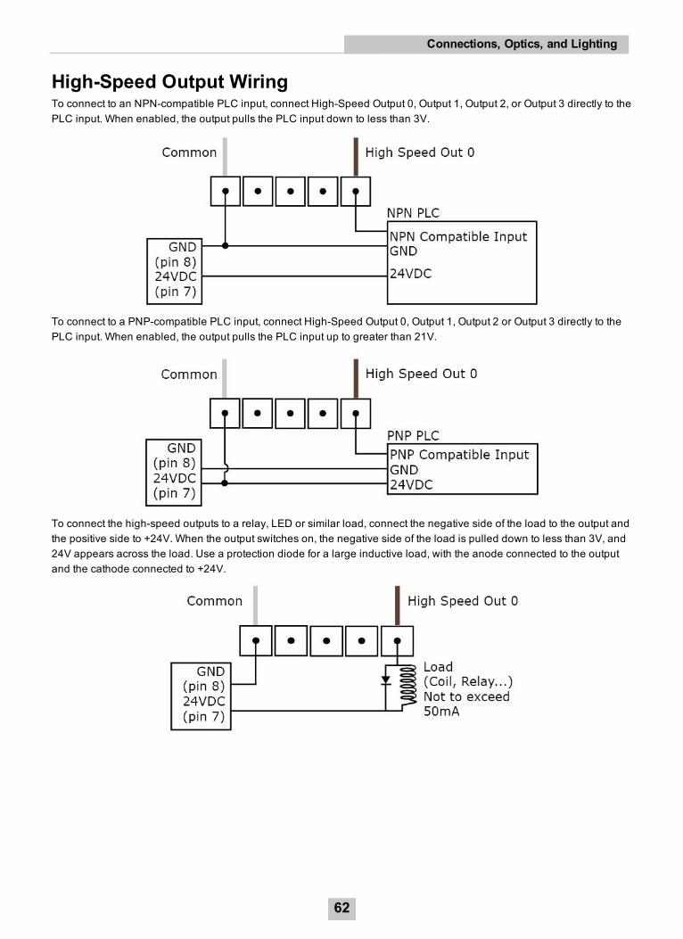
High-Speed Output WiringTo connect to an NPN-compatible PLC input, connect High-Speed Output 0, Output 1, Output 2, or Output 3 directly to thePLC input. When enabled, the output pulls the PLC input down to less than 3V.
To connect to a PNP-compatible PLC input, connect High-Speed Output 0, Output 1, Output 2 or Output 3 directly to thePLC input. When enabled, the output pulls the PLC input up to greater than 21V.
To connect the high-speed outputs to a relay, LED or similar load, connect the negative side of the load to the output andthe positive side to +24V. When the output switches on, the negative side of the load is pulled down to less than 3V, and24V appears across the load. Use a protection diode for a large inductive load, with the anode connected to the outputand the cathode connected to +24V.
62
Connections, Optics, and Lighting
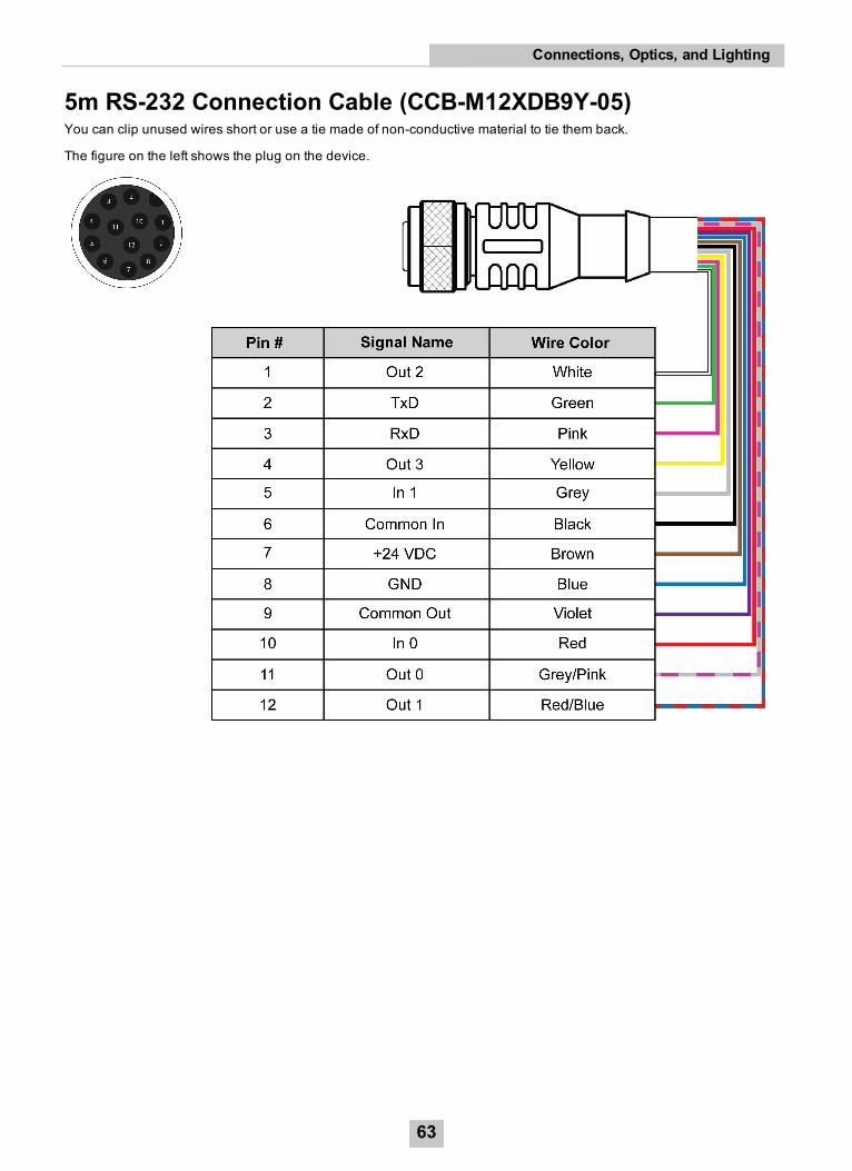
5m RS-232 Connection Cable (CCB-M12XDB9Y-05)You can clip unused wires short or use a tie made of non-conductive material to tie them back.
The figure on the left shows the plug on the device.
63
Connections, Optics, and Lighting
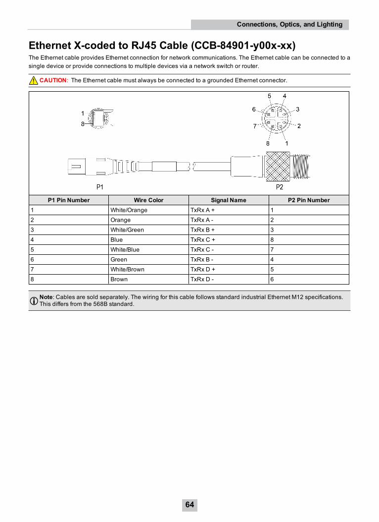
Ethernet X-coded to RJ45 Cable (CCB-84901-y00x-xx)The Ethernet cable provides Ethernet connection for network communications. The Ethernet cable can be connected to asingle device or provide connections to multiple devices via a network switch or router.
CAUTION: The Ethernet cable must always be connected to a grounded Ethernet connector.
P1 Pin Number Wire Color Signal Name P2 Pin Number1 White/Orange TxRx A + 12 Orange TxRx A - 23 White/Green TxRx B + 34 Blue TxRx C + 85 White/Blue TxRx C - 76 Green TxRx B - 47 White/Brown TxRx D + 58 Brown TxRx D - 6
Note: Cables are sold separately. The wiring for this cable follows standard industrial Ethernet M12 specifications.This differs from the 568B standard.
64
Connections, Optics, and Lighting
Cleaning and MaintenanceCleaning the Reader Housing
To clean the outside of the reader housing, use a small amount of mild detergent cleaner or isopropyl alcohol on acleaning cloth. Do not pour the cleaner directly onto the reader housing.
CAUTION: Do not attempt to clean any DataMan product with harsh or corrosive solvents, including lye, methylethyl ketone (MEK) or gasoline.
Cleaning the Reader Lens Cover
To remove dust from the lens cover, use a pressurized air duster. The air must be free of oil, moisture or othercontaminants that could remain on the lens cover. To clean the plastic window of the lens cover, use a small amount ofisopropyl alcohol on a cleaning cloth. Do not scratch the plastic window. Do not pour the alcohol directly on the plasticwindow.
65
Cleaning and Maintenance

Compliance Information, Warnings and NoticesPrecautionsTo reduce the risk of injury or equipment damage, observe the following precautions when you install the Cognexproduct:
l The reader is intended to be supplied by a UL or NRTL listed power supply with a 24VDC output rated for at least2A continuous and a maximum short circuit current rating of less than 8A and a maximum power rating of lessthan 100VA and marked Class 2 or Limited Power Source (LPS). Any other voltage creates a risk of fire or shockand can damage the components. Applicable national and local wiring standards and rules must be followed.
l Route cables and wires away from high-current wiring or high-voltage power sources to reduce the risk ofdamage or malfunction from the following causes: over-voltage, line noise, electrostatic discharge (ESD), powersurges, or other irregularities in the power supply.
l Do not install Cognex products where they are exposed to environmental hazards such as excessive heat, dust,moisture, humidity, impact, vibration, corrosive substances, flammable substances, or static electricity.
l Do not expose the image sensor to laser light. Image sensors can be damaged by direct, or reflected, laser light.If your application requires laser light that might strike the image sensor, use a lens filter at the correspondinglaser wavelength. For suggestions, contact your local integrator or application engineer.
l Changes or modifications not expressly approved by the party responsible for regulatory compliance could voidthe user’s authority to operate the equipment.
l Include service loops with cable connections.
l Ensure that the cable bend radius begins at least six inches from the connector. Cable shielding can bedegraded or cables can be damaged or wear out faster if a service loop or bend radius is tighter than 10X thecable diameter.
l This device should be used in accordance with the instructions in this manual.
l All specifications are for reference purposes only and can change without notice.
66
Compliance Information, Warnings and Notices
Regulations/ConformityNote: For the most current CE declaration and regulatory conformity information, see the Cognex support site:cognex.com/support.
DataMan 370 Series readers have Regulatory Model R00051 and meet or exceed the requirements of all applicablestandards organizations for safe operation. However, as with any electrical equipment, the best way to ensure safeoperation is to operate them according to the agency guidelines that follow. Please read these guidelines carefullybefore using your device.
Safety and RegulatoryManufacturer Cognex Corporation
One Vision DriveNatick, MA 01760 USA
USA TÜV SÜD AM SCC/NRTL OSHA Scheme for UL/CAN 61010-1.FCC Part 15, Class AThis equipment has been tested and found to comply with the limits for a Class A digital device,pursuant to part 15 of the FCC Rules. These limits are designed to provide reasonable protectionagainst harmful interference when the equipment is operated in a commercial environment. Thisequipment generates, uses, and can radiate radio frequency energy and, if not installed and used inaccordance with the instruction manual, may cause harmful interference to radio communications.Operation of this equipment in a residential area is likely to cause harmful interference in which casethe user will be required to correct the interference at his own expense.
Canada TÜV SÜD AM SCC/NRTL OSHA Scheme for UL/CAN 61010-1.ICES-003, Class AThis Class A digital apparatus complies with Canadian ICES-003. Cet appareil numérique de laclasse A est conforme à la norme NMB-003 du Canada.
Europe The CE mark on the product indicates that the system has been tested to and conforms to theprovisions noted within the 2014/30/EU Electromagnetic Compatibility Directive and the 2011/65/EURoHS Directive. For further information, please contact: Cognex Corporation, One Vision Drive, Natick,MA 01760, USA. Cognex Corporation shall not be liable for use of our product with equipment (i.e.,power supplies, personal computers, etc.) that is not CE.
Korea A급 기기(업무용 방송통신기자재):이 기기는 업무용(A급)전자파적합기기로서 판 매자 또는 사용자는 이 점을 주의하시기 바라 며 ,가정외의 지역에서 사용하는 것을 목적으 로 합니다 .
InternationalProduct Safety
Conforms to IEC 61010-1, CAN/CSA-C22.2 No. 61010-1:2012 + UPD No. 1:2015-07, UL 61010-1:2012 + R:2015-07, UL 61010-1:2012 + R:2015-07, EN 61010-1:2010.
CB TÜV SÜD AM, IEC/EN 61010-1. CB report available upon request.
For European Community UsersCognex complies with Directive 2012/19/EU OF THE EUROPEAN PARLIAMENT AND OF THE COUNCIL of 4 July 2012on waste electrical and electronic equipment (WEEE).
This product has required the extraction and use of natural resources for its production. It may contain hazardoussubstances that could impact health and the environment, if not properly disposed.
In order to avoid the dissemination of those substances in our environment and to diminish the pressure on the naturalresources, we encourage you to use the appropriate take-back systems for product disposal. Those systems will reuse orrecycle most of the materials of the product you are disposing in a sound way.
The crossed out wheeled bin symbol informs you that the product should not be disposed of along with municipalwaste and invites you to use the appropriate separate take-back systems for product disposal.
67
Compliance Information, Warnings and Notices

If you need more information on the collection, reuse, and recycling systems, please contact your local or regional wasteadministration.
You may also contact your supplier for more information on the environmental performance of this product.
Reader Programming Codes
Reset Scanner to Factory Defaults Reboot Scanner
68
Compliance Information, Warnings and Notices

Copyright © 2019Cognex Corporation. All Rights Reserved.