Embed Size (px)
Citation preview
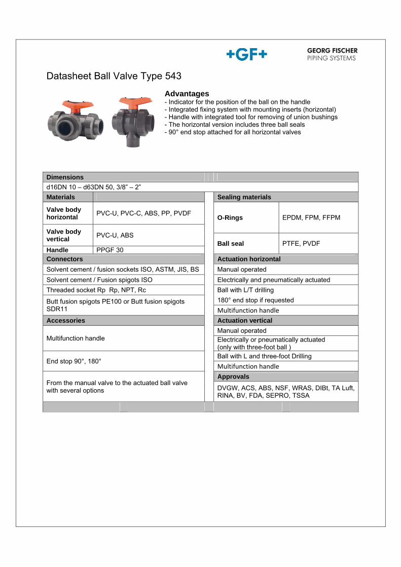
Datasheet Ball Valve Type 543
Dimensions
d16DN 10 – d63DN 50, 3/8” – 2”
Materials Sealing materials
Valve body horizontal
PVC-U, PVC-C, ABS, PP, PVDF O-Rings EPDM, FPM, FFPM
Valve body vertical
PVC-U, ABS Ball seal PTFE, PVDF
Handle PPGF 30 Connectors Actuation horizontal
Solvent cement / fusion sockets ISO, ASTM, JIS, BS Manual operated
Solvent cement / Fusion spigots ISO Electrically and pneumatically actuated
Threaded socket Rp Rp, NPT, Rc Ball with L/T drilling
Butt fusion spigots PE100 or Butt fusion spigots SDR11
180° end stop if requested
Multifunction handle
Accessories Actuation vertical
Multifunction handle Manual operated
Electrically or pneumatically actuated (only with three-foot ball )
End stop 90°, 180° Ball with L and three-foot Drilling
Multifunction handle
From the manual valve to the actuated ball valve with several options
Approvals
DVGW, ACS, ABS, NSF, WRAS, DIBt, TA Luft, RINA, BV, FDA, SEPRO, TSSA
Advantages - Indicator for the position of the ball on the handle - Integrated fixing system with mounting inserts (horizontal) - Handle with integrated tool for removing of union bushings - The horizontal version includes three ball seals - 90° end stop attached for all horizontal valves
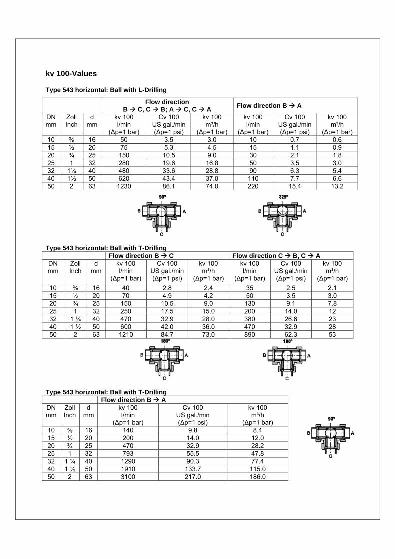
kv 100-Values Type 543 horizontal: Ball with L-Drilling
Type 543 horizontal: Ball with T-Drilling
Flow direction B C Flow direction C B, C A DN mm
Zoll Inch
d mm
kv 100 l/min
(Δp=1 bar)
Cv 100 US gal./min (Δp=1 psi)
kv 100 m³/h
(Δp=1 bar)
kv 100 l/min
(Δp=1 bar)
Cv 100 US gal./min (Δp=1 psi)
kv 100 m³/h
(Δp=1 bar)
10 ⅜ 16 40 2.8 2.4 35 2.5 2.1 15 ½ 20 70 4.9 4.2 50 3.5 3.0 20 ¾ 25 150 10.5 9.0 130 9.1 7.8 25 1 32 250 17.5 15.0 200 14.0 12 32 1 ¼ 40 470 32.9 28.0 380 26.6 23 40 1 ½ 50 600 42.0 36.0 470 32.9 28 50 2 63 1210 84.7 73.0 890 62.3 53
Type 543 horizontal: Ball with T-Drilling
Flow direction B A DN mm
Zoll Inch
d mm
kv 100 l/min
(Δp=1 bar)
Cv 100 US gal./min (Δp=1 psi)
kv 100 m³/h
(Δp=1 bar) 10 ⅜ 16 140 9.8 8.4 15 ½ 20 200 14.0 12.0 20 ¾ 25 470 32.9 28.2 25 1 32 793 55.5 47.8 32 1 ¼ 40 1290 90.3 77.4 40 1 ½ 50 1910 133.7 115.0 50 2 63 3100 217.0 186.0
Flow direction
B C, C B; A C, C A Flow direction B A
DN mm
Zoll Inch
d mm
kv 100 l/min
(Δp=1 bar)
Cv 100 US gal./min (Δp=1 psi)
kv 100 m³/h
(Δp=1 bar)
kv 100 l/min
(Δp=1 bar)
Cv 100 US gal./min (Δp=1 psi)
kv 100 m³/h
(Δp=1 bar) 10 ⅜ 16 50 3.5 3.0 10 0.7 0.6 15 ½ 20 75 5.3 4.5 15 1.1 0.9 20 ¾ 25 150 10.5 9.0 30 2.1 1.8 25 1 32 280 19.6 16.8 50 3.5 3.0 32 1¼ 40 480 33.6 28.8 90 6.3 5.4 40 1½ 50 620 43.4 37.0 110 7.7 6.6 50 2 63 1230 86.1 74.0 220 15.4 13.2
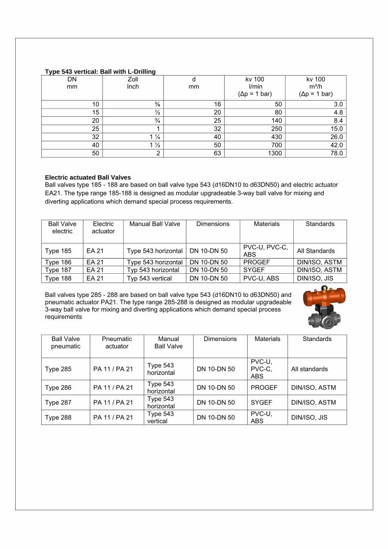
Type 543 vertical: Ball with L-Drilling DN mm
Zoll Inch
d mm
kv 100 l/min
(Δp = 1 bar)
kv 100 m³/h
(Δp = 1 bar)
10 ⅜ 16 50 3.015 ½ 20 80 4.820 ¾ 25 140 8.425 1 32 250 15.032 1 ¼ 40 430 26.040 1 ½ 50 700 42.050 2 63 1300 78.0
Electric actuated Ball Valves Ball valves type 185 - 188 are based on ball valve type 543 (d16DN10 to d63DN50) and electric actuator EA21. The type range 185-188 is designed as modular upgradeable 3-way ball valve for mixing and diverting applications which demand special process requirements.
Ball Valve
electric Electric actuator
Manual Ball Valve Dimensions Materials Standards
Type 185 EA 21 Type 543 horizontal DN 10-DN 50 PVC-U, PVC-C, ABS
All Standards
Type 186 EA 21 Type 543 horizontal DN 10-DN 50 PROGEF DIN/ISO, ASTM Type 187 EA 21 Typ 543 horizontal DN 10-DN 50 SYGEF DIN/ISO, ASTM Type 188 EA 21 Typ 543 vertical DN 10-DN 50 PVC-U, ABS DIN/ISO, JIS
Ball valves type 285 - 288 are based on ball valve type 543 (d16DN10 to d63DN50) and pneumatic actuator PA21. The type range 285-288 is designed as modular upgradeable 3-way ball valve for mixing and diverting applications which demand special process requirements
Ball Valve pneumatic
Pneumatic actuator
Manual Ball Valve
Dimensions Materials Standards
Type 285 PA 11 / PA 21 Type 543 horizontal
DN 10-DN 50 PVC-U, PVC-C, ABS
All standards
Type 286 PA 11 / PA 21 Type 543 horizontal
DN 10-DN 50 PROGEF DIN/ISO, ASTM
Type 287 PA 11 / PA 21 Type 543 horizontal
DN 10-DN 50 SYGEF DIN/ISO, ASTM
Type 288 PA 11 / PA 21 Type 543 vertical
DN 10-DN 50 PVC-U, ABS
DIN/ISO, JIS

0123456789
10111213141516
-50 -40 -30 -20 -10 0 10 20 30 40 50 60 70 80 90T (°C)
P (b
ar)
0
20
40
60
80
100
120
140
160
180
200
220
-58 -38 -18 2 22 42 62 82 102 122 142 162 182T (°F)
P (p
si)
PN10
ABSType 543
P0900373
0123456789
10111213141516
-50 -40 -30 -20 -10 0 10 20 30 40 50 60 70 80 90T (°C)
P (b
ar)
0
20
40
60
80
100
120
140
160
180
200
220
-58 -38 -18 2 22 42 62 82 102 122 142 162 182T (°F)
P (p
si)
PN10
PVC-CType 543
P0900377
0123456789
10111213141516
-50 -40 -30 -20 -10 0 10 20 30 40 50 60 70 80 90 100 110 120 130 140 150T (°C)
P (b
ar)
0
20
40
60
80
100
120
140
160
180
200
220
-58 -28 2 32 62 92 122 152 182 212 242 272 302T (°F)
P (p
si)
PPType 543
P0900374
PN 10
0123456789
10111213141516
-50 -40 -30 -20 -10 0 10 20 30 40 50 60 70 80 90T (°C)
P (b
ar)
0
20
40
60
80
100
120
140
160
180
200
220
-58 -38 -18 2 22 42 62 82 102 122 142 162 182T (°F)
P (p
si)
PN10
PVC-UType 543
P0900376
Design Ball Valve horizontal
Ball Valve vertical P/ T-Diagrams PVC-U PVC-C
P: Permissible pressure in bar, psi, T: Temperature in °C, °F P: Permissible pressure in bar, psi, T: Temperature in °C, °F
ABS PP
P: Permissible pressure in bar, psi, T: Temperature in °C, °F P: Permissible pressure in bar, psi, T: Temperature in °C, °F
1. Body 2. Union nut 3. Connecting part 4. Union nut 5. Ball L/T 6. Stem 7. ball seal 8. Backing seal 9. Body seal 10. Union seal 11. Stem seal 12. Standard handle 13. Handle clip
1. Body 2. Union nut 3. Connecting part 4. Union nut 5. Ball 6. Stem 7. Ball seal 8. Backing seal 9. Body seal 10. Anschlussteildichtung 11. Stem seal 12. Standard handle 13. Handle clip 15. Multifunction handle 16. Spacer
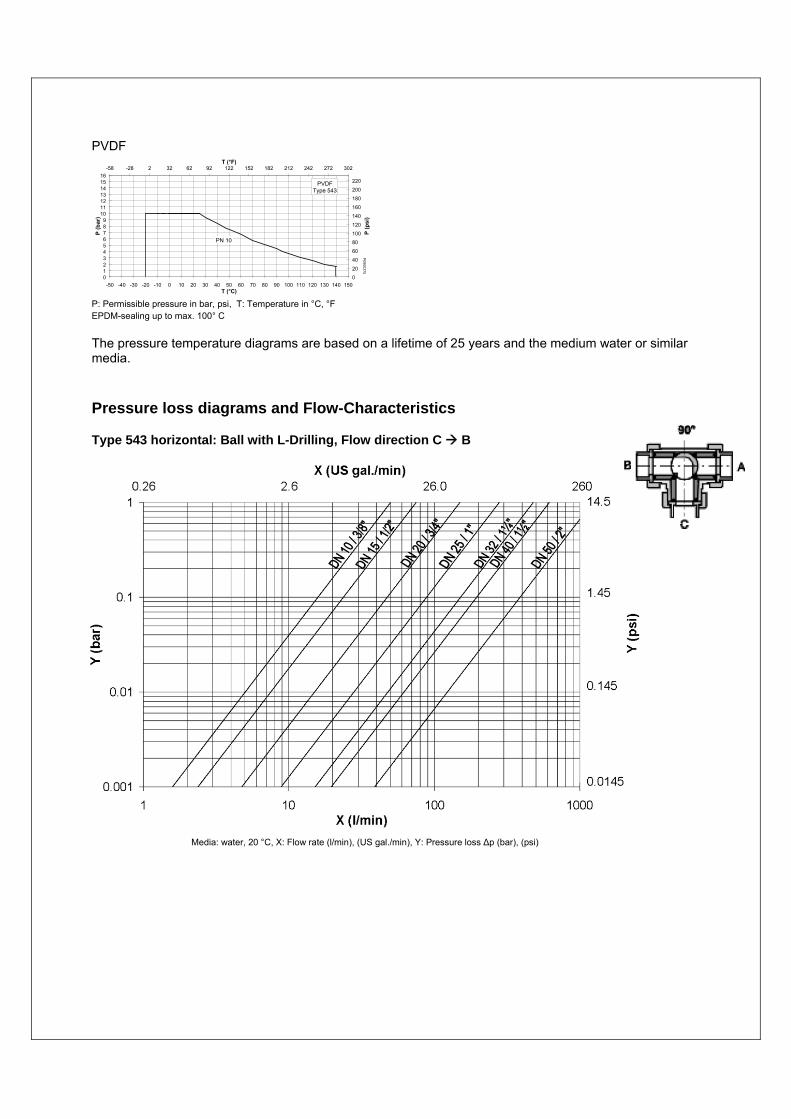
PVDF
P: Permissible pressure in bar, psi, T: Temperature in °C, °F EPDM-sealing up to max. 100° C
The pressure temperature diagrams are based on a lifetime of 25 years and the medium water or similar media.
Pressure loss diagrams and Flow-Characteristics
Type 543 horizontal: Ball with L-Drilling, Flow direction C B
Medium: Wasser,
0123456789
10111213141516
-50 -40 -30 -20 -10 0 10 20 30 40 50 60 70 80 90 100 110 120 130 140 150T (°C)
P (b
ar)
0
20
40
60
80
100
120
140
160
180
200
220
-58 -28 2 32 62 92 122 152 182 212 242 272 302T (°F)
P (p
si)
PVDFType 543
PN 10
P0900375
Media: water, 20 °C, X: Flow rate (l/min), (US gal./min), Y: Pressure loss Δp (bar), (psi)
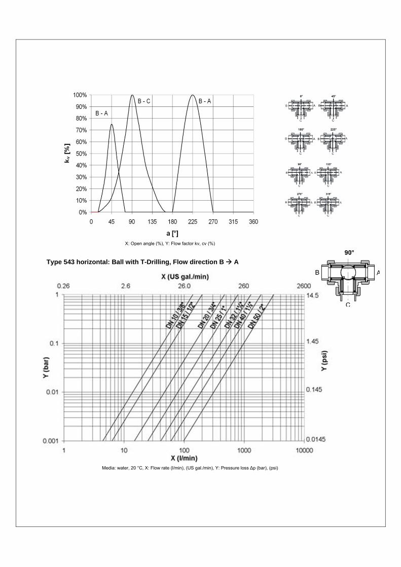
Type 543 horizontal: Ball with T-Drilling, Flow direction B A
Media: water, 20 °C, X: Flow rate (l/min), (US gal./min), Y: Pressure loss Δp (bar), (psi)
X: Open angle (%), Y: Flow factor kv, cv (%)
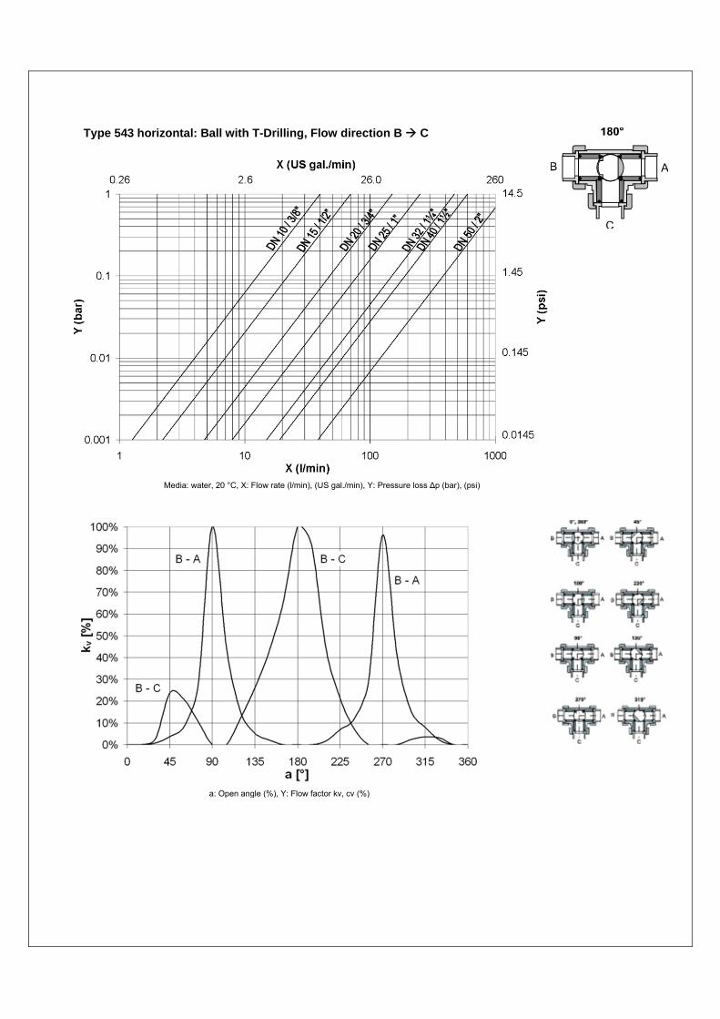
Type 543 horizontal: Ball with T-Drilling, Flow direction B C
Media: water, 20 °C, X: Flow rate (l/min), (US gal./min), Y: Pressure loss Δp (bar), (psi)
a: Open angle (%), Y: Flow factor kv, cv (%)
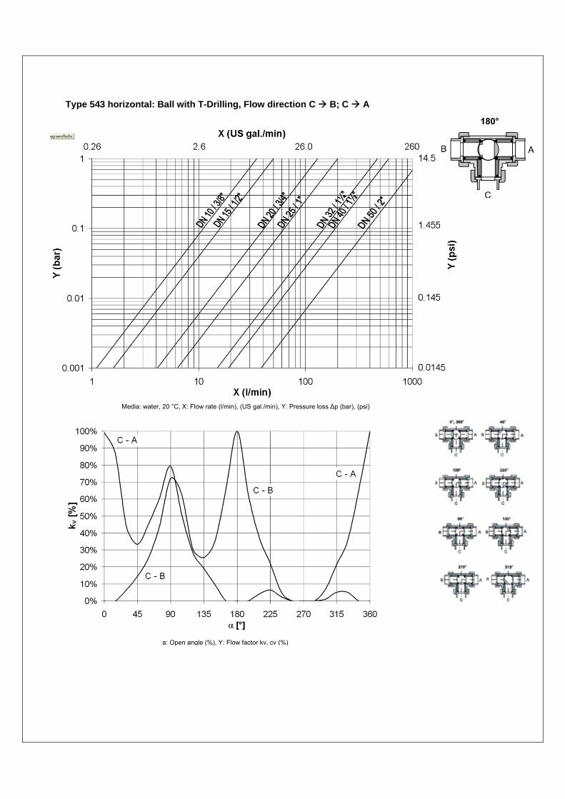
Type 543 horizontal: Ball with T-Drilling, Flow direction C B; C A
Media: water, 20 °C, X: Flow rate (l/min), (US gal./min), Y: Pressure loss Δp (bar), (psi)
a: Open angle (%), Y: Flow factor kv, cv (%)
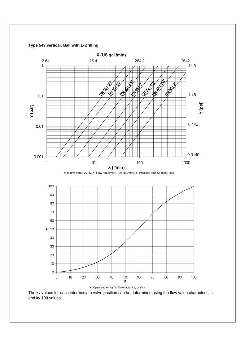
Type 543 vertical: Ball with L-Drilling
The kv values for each intermediate valve position can be determined using the flow value characteristic and kv 100 values..
medium: water, 20 °C, X: Flow rate (l/min), (US gal./min), Y: Pressure loss Δp (bar), (psi)
X: Open angle (%), Y: Flow factor kv, cv (%)
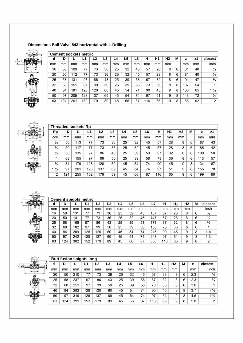
Dimensions Ball Valve 543 horizontal with L-Drilling
Cement sockets metric d D L L1 L2 L3 L4 L5 L6 H H1 H2 M z z1 closest
mm mm mm mm mm mm mm mm mm mm mm mm mm mm inch
16 50 109 77 73 36 25 32 45 57 28 8 6 81 40 ⅜
20 50 112 77 73 36 25 32 45 57 28 8 6 81 40 ½
25 58 131 97 86 43 25 39 58 67 32 8 6 94 47 ¾
32 68 151 97 99 50 25 39 58 73 36 8 6 107 54 1
40 84 181 128 120 60 45 54 74 90 45 9 8 130 65 1 ¼
50 97 205 128 137 69 45 54 74 97 51 9 8 143 72 1 ½
63 124 261 152 179 89 45 66 87 116 65 9 8 185 92 2
Threaded sockets Rp Rp D L L1 L2 L3 L4 L5 L6 H H1 H2 M z z1
Zoll mm mm mm mm mm mm mm mm mm mm mm mm mm
⅜ 50 113 77 73 36 25 32 45 57 28 8 6 87 43
½ 50 117 77 73 36 25 32 45 57 28 8 6 85 42
¾ 58 135 97 86 43 25 39 58 67 32 8 6 100 50
1 68 155 97 99 50 25 39 58 73 36 8 6 113 57
1 ¼ 84 179 128 120 60 45 54 74 90 45 9 8 134 67
1 ½ 97 201 128 137 69 45 54 74 97 51 9 8 155 78
2 124 255 152 179 89 45 66 87 116 65 9 8 199 99
Cement spigots metric d D L L1 L2 L3 L4 L5 L6 L7 H H1 H2 M closest
mm mm mm mm mm mm mm mm mm mm mm mm mm inch 16 50 131 77 73 36 25 32 45 137 57 28 8 6 ⅜ 20 50 141 77 73 36 25 32 45 147 57 28 8 6 ½ 25 58 165 97 86 43 25 39 58 171 67 32 8 6 ¾ 32 68 182 97 99 50 25 39 58 188 73 36 8 6 1 40 84 209 128 120 60 45 54 74 215 90 45 9 8 1 ¼ 50 97 242 128 137 69 45 54 74 248 97 51 9 8 1 ½ 63 124 302 152 179 89 45 66 87 308 116 65 9 8 2
Butt fusion spigots long d D L L1 L2 L3 L4 L5 L6 H H1 H2 M e closest
mm mm mm mm mm mm mm mm mm mm mm mm mm inch
20 50 210 77 73 36 25 32 45 57 28 8 6 2.3 ½
25 58 237 97 86 43 25 39 58 67 32 8 6 2.3 ¾
32 68 251 97 99 50 25 39 58 73 36 8 6 3.0 1
40 84 283 128 120 60 45 54 74 90 45 9 8 3.7 1 ¼
50 97 319 128 137 69 45 54 74 97 51 9 8 4.6 1 ½
63 124 399 152 179 89 45 66 87 116 65 9 8 5.8 2
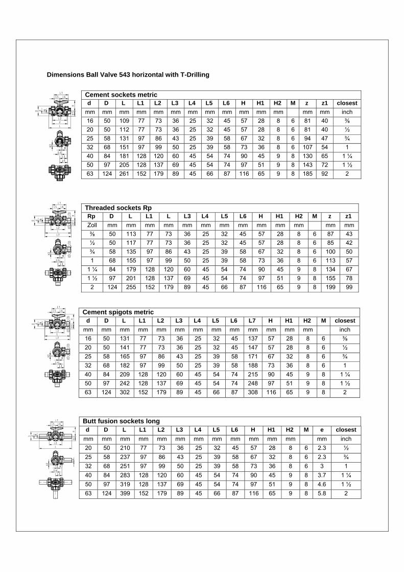
Dimensions Ball Valve 543 horizontal with T-Drilling
Threaded sockets Rp Rp D L L1 L L3 L4 L5 L6 H H1 H2 M z z1
Zoll mm mm mm mm mm mm mm mm mm mm mm mm mm
⅜ 50 113 77 73 36 25 32 45 57 28 8 6 87 43
½ 50 117 77 73 36 25 32 45 57 28 8 6 85 42
¾ 58 135 97 86 43 25 39 58 67 32 8 6 100 50
1 68 155 97 99 50 25 39 58 73 36 8 6 113 57
1 ¼ 84 179 128 120 60 45 54 74 90 45 9 8 134 67
1 ½ 97 201 128 137 69 45 54 74 97 51 9 8 155 78
2 124 255 152 179 89 45 66 87 116 65 9 8 199 99
Cement spigots metric d D L L1 L2 L3 L4 L5 L6 L7 H H1 H2 M closest
mm mm mm mm mm mm mm mm mm mm mm mm mm inch
16 50 131 77 73 36 25 32 45 137 57 28 8 6 ⅜
20 50 141 77 73 36 25 32 45 147 57 28 8 6 ½
25 58 165 97 86 43 25 39 58 171 67 32 8 6 ¾
32 68 182 97 99 50 25 39 58 188 73 36 8 6 1
40 84 209 128 120 60 45 54 74 215 90 45 9 8 1 ¼
50 97 242 128 137 69 45 54 74 248 97 51 9 8 1 ½
63 124 302 152 179 89 45 66 87 308 116 65 9 8 2
Cement sockets metric d D L L1 L2 L3 L4 L5 L6 H H1 H2 M z z1 closest
mm mm mm mm mm mm mm mm mm mm mm mm mm mm inch
16 50 109 77 73 36 25 32 45 57 28 8 6 81 40 ⅜
20 50 112 77 73 36 25 32 45 57 28 8 6 81 40 ½
25 58 131 97 86 43 25 39 58 67 32 8 6 94 47 ¾
32 68 151 97 99 50 25 39 58 73 36 8 6 107 54 1
40 84 181 128 120 60 45 54 74 90 45 9 8 130 65 1 ¼
50 97 205 128 137 69 45 54 74 97 51 9 8 143 72 1 ½
63 124 261 152 179 89 45 66 87 116 65 9 8 185 92 2
Butt fusion sockets long d D L L1 L2 L3 L4 L5 L6 H H1 H2 M e closest
mm mm mm mm mm mm mm mm mm mm mm mm mm inch
20 50 210 77 73 36 25 32 45 57 28 8 6 2.3 ½
25 58 237 97 86 43 25 39 58 67 32 8 6 2.3 ¾
32 68 251 97 99 50 25 39 58 73 36 8 6 3 1
40 84 283 128 120 60 45 54 74 90 45 9 8 3.7 1 ¼
50 97 319 128 137 69 45 54 74 97 51 9 8 4.6 1 ½
63 124 399 152 179 89 45 66 87 116 65 9 8 5.8 2
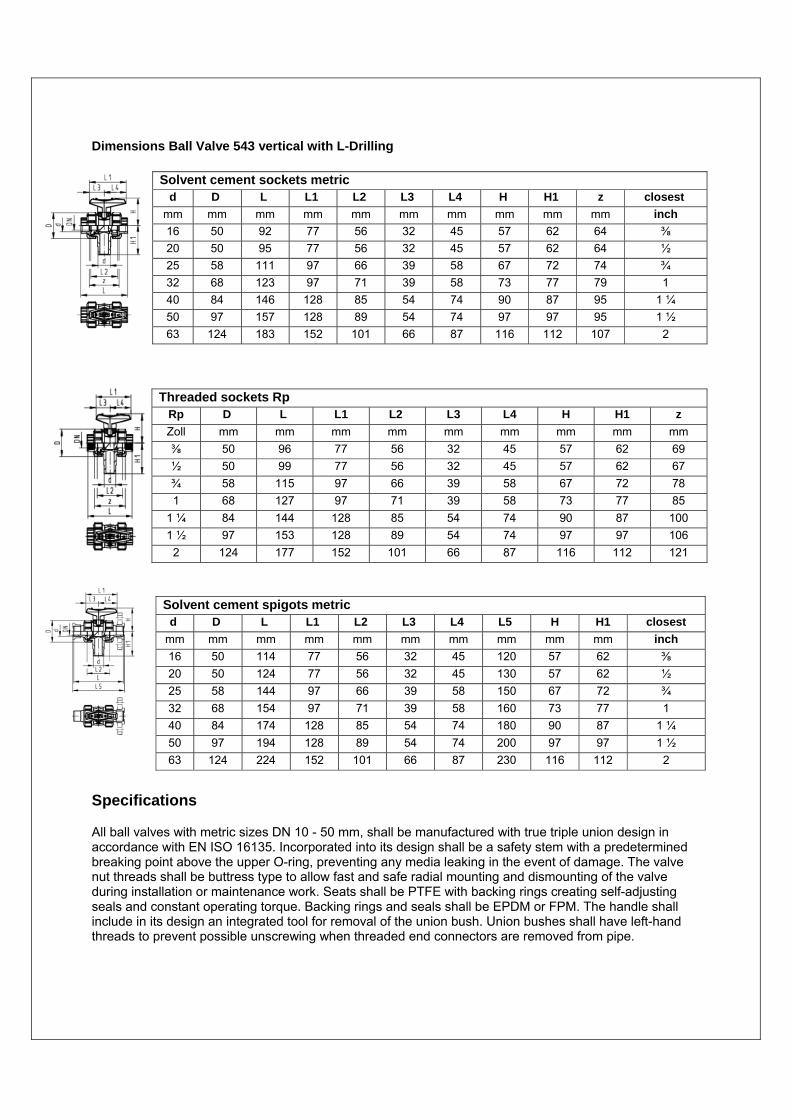
Dimensions Ball Valve 543 vertical with L-Drilling
Solvent cement spigots metric d D L L1 L2 L3 L4 L5 H H1 closest
mm mm mm mm mm mm mm mm mm mm inch
16 50 114 77 56 32 45 120 57 62 ⅜
20 50 124 77 56 32 45 130 57 62 ½
25 58 144 97 66 39 58 150 67 72 ¾
32 68 154 97 71 39 58 160 73 77 1
40 84 174 128 85 54 74 180 90 87 1 ¼
50 97 194 128 89 54 74 200 97 97 1 ½
63 124 224 152 101 66 87 230 116 112 2
Specifications
All ball valves with metric sizes DN 10 - 50 mm, shall be manufactured with true triple union design in accordance with EN ISO 16135. Incorporated into its design shall be a safety stem with a predetermined breaking point above the upper O-ring, preventing any media leaking in the event of damage. The valve nut threads shall be buttress type to allow fast and safe radial mounting and dismounting of the valve during installation or maintenance work. Seats shall be PTFE with backing rings creating self-adjusting seals and constant operating torque. Backing rings and seals shall be EPDM or FPM. The handle shall include in its design an integrated tool for removal of the union bush. Union bushes shall have left-hand threads to prevent possible unscrewing when threaded end connectors are removed from pipe.
Solvent cement sockets metric d D L L1 L2 L3 L4 H H1 z closest
mm mm mm mm mm mm mm mm mm mm inch
16 50 92 77 56 32 45 57 62 64 ⅜
20 50 95 77 56 32 45 57 62 64 ½
25 58 111 97 66 39 58 67 72 74 ¾
32 68 123 97 71 39 58 73 77 79 1
40 84 146 128 85 54 74 90 87 95 1 ¼
50 97 157 128 89 54 74 97 97 95 1 ½
63 124 183 152 101 66 87 116 112 107 2
Threaded sockets Rp Rp D L L1 L2 L3 L4 H H1 z
Zoll mm mm mm mm mm mm mm mm mm
⅜ 50 96 77 56 32 45 57 62 69
½ 50 99 77 56 32 45 57 62 67
¾ 58 115 97 66 39 58 67 72 78
1 68 127 97 71 39 58 73 77 85
1 ¼ 84 144 128 85 54 74 90 87 100
1 ½ 97 153 128 89 54 74 97 97 106
2 124 177 152 101 66 87 116 112 121
Following accessories shall be available: • A Multi-Functional Model (MFM) in PPGF equipped with internal limit switches for reliable electrical position feedback, is mounted directly between the valve body and the valve handle. This MFM is also the necessary interface for later mounting of actuators. • Mounting plate in PPGF with integrated inserts for later screw mounting on any support • Lockable multi-functional handle Electric actuated Ball Valves Electric actuators shall be either actuator 1 (sizes DN10-50 mm). It shall be manufactured in accordance with EN 61010-1, EC directives 2004/108/EC (EMC) and 2006/95/EC, LVD and needs to be CE marked. Actuator housing shall be made of PPGF (polypropylene glass fibre reinforced), flame retardant with external stainless steel screws. All electric actuators shall have an integrated emergency manual override and integrated optical position indication. Electric actuator types shall have the following accessory options: • Fail-safe unit • Heating element • Cycle extension, cycle time monitoring, and cycle counting • Motor current monitoring • Position signalisation • Positioner • Limit switch kits Ag-Ni, Au, NPN, PNP, NAMUR • AS Interface Plug Module Electric actuator specifications of the actuators shall be as follows Specification Actuator 1 Nominal torque (Nm) 10 Control time (s/90°)* 5 Cycles at 20°C * 250,000 Duty cycles ED at 20°C 100% Protection class IP65 per EN 60529 - IP67 (for vertical cable mounting and wall feed through) Voltage 100-230, 50-60 Hz or 24V=/24V, 50/60 Hz versions
* = at nominal torque Pneumatic actuated Ball Valves Pneumatic actuators shall be actuator 1 (for valve sizes DN 15-25 mm) or actuator 2 (for valve sizes DN 32-50 mm). Pneumatic actuators shall be available as fail safe close, fail safe open and double acting and have an integrated optical position indication. Actuator housing shall be made of Polypropylene fibre glass reinforced (PPGF) and flame retardant. Actuators shall contain a preloaded spring assembly to ensure safe actuator operation and maintenance. Actuators shall contain integrated Namur interface for the easy mounting of positioners, limit switches and accessories. The valve shall be equipped with a Multi-functional-module for reliable electric feedback, mounted directly between the valve body and the actuator as manufacturer standard. All pneumatically actuated ball valves shall have the following accessories available: • Pilot valve remote or direct mounted in voltages 24VDC/AC, 110VAC, 230VAC • Positioner • Limit switch kits Ag-Ni, Au, NPN, PNP • Stroke limiter • Manual override for all sizes up to d 63 mm • AS Interface control module with incorporated position feedback and a solenoid pilot valve Planning Fundamentals The following link will lead you to the Georg Fischer Planning Fundamentals. These detailed documents will support you by choosing the right valve for your application. http://www.gfps.com/content/gfps/com/en/support_and_services/planning_assistance/planning_fundamentals.html?lang=en


![KTM METALTITE BALL VALVES FLOATING AND TRUNNION TYPE · 2019-07-04 · KTM METALTITE® BALL VALVES FLOATING AND TRUNNION TYPE TECHNICAL SPECIFICATION Type Manufacturing range [1]](https://img.pdfslide.net/doc/110x75/5ed4f51333c96f5aa039d80d/ktm-metaltite-ball-valves-floating-and-trunnion-type-2019-07-04-ktm-metaltite.jpg)