Embed Size (px)
Citation preview
SUBJECT TO CHANGE WITHOUT NOTICEThis manual superseded all previous versions – please keep for future reference
DIGITAL MULTIMETERGamma 12
www.sifamtinsley.co.uk
DATASHEET Issue 1.0
Multifunction Meters
Transducers & Isolators
Temperature Controllers
Converters & Recorders
Digital Panel Meters
Current Transformers
Analogue Panel Meters
Shunts
Digital Multimeters
Clamp Meters
Insulation Testers
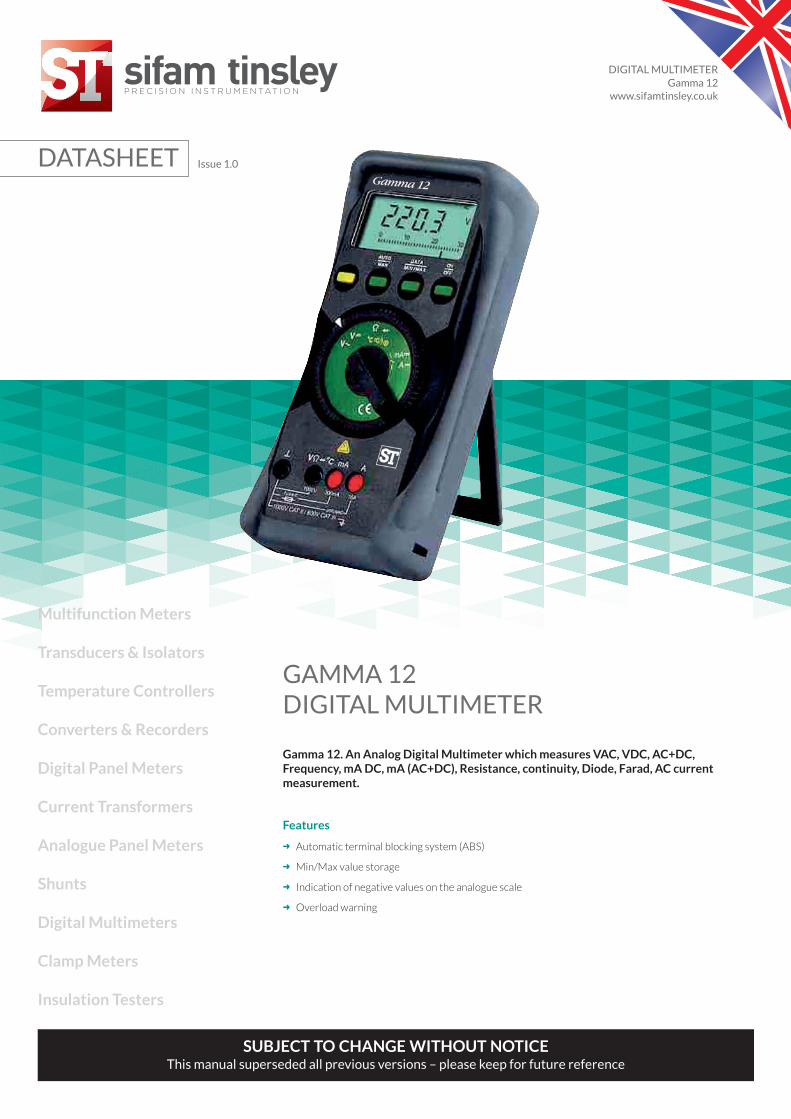
GAMMA 12DIGITAL MULTIMETER
Gamma 12. An Analog Digital Multimeter which measures VAC, VDC, AC+DC,Frequency, mA DC, mA (AC+DC), Resistance, continuity, Diode, Farad, AC currentmeasurement.
Features
➜ Automatic terminal blocking system (ABS)
➜ Min/Max value storage
➜ Indication of negative values on the analogue scale
➜ Overload warning

DIGITAL MULTIMETER
Gamma 12 1Issue 1.0
Application
Gamma 12 is the Analog Digital Multimeter which measures VAC, VDC, VAC+DC,Frequency,mA DC, mA (AC+DC), Resistance, continuity, Diode, Farad, AC current measurement.
Product Features
Automatic The automatic Terminal blocking systemTerminal prevents incorrect connection of the test leadsBlocking System and incorrect selection of the measured(ABS) quantity. This reduces danger to the user,
the meter and the system to a remarkableextent.
Interface And The multimeters are fitted with a serialSoftware RS-232 C interface via which the measuredRISH com 100 values can be transmitted to a PC.
These values, electrically isolated, aretransmitted to the attachable interfaceadaptor with infrared light through the case*
MIN / MAX In addition to the display of the actualValue Storage measured value, the minimum or maximum
value can constantly be updated and stored.Indication Of When measuring DC quantities, also negativeNegative Values values are shown on the analogue scale so thatOn The Analogue variations of the measured value can beScale observed at the zero point.Indication Of The measuring principle employed permitsNegative Values the measurement of the root-mean-squareOn The Analogue value (TRMS) of AC quantities and mixedScale quantities (AC and DC) regardless of the
waveform.Automatic Data The DATA HOLD function makes it possibleHold* to hold the digitally displayed measured
value. According to a patented method, it isensured that no freak value but the actualmeasured value is held in the case of rapidchanges in measured quantities. The heldmeasured value appears on the digital display.The actual measured value continues to beshown on the analogue scale.
Autoranging / The measured values are selected with rotaryManual Range switch.Selection The measuring range is automatically
matched to the measured value.The measuring range can also be selectedmanually via the AUTO/MAN push button
Continuity Test This permits testing for short circuit and open circuit. In addition to the display, a facility of sound signal is available.
Temperature It is possible to use all models of Gamma 12,Measurement in direct connection of temperature sensor
Pt 100 / Pt 1000. The meters automaticallydetects the type of sensors connected to it &displays directly measured temperature.
Signalling in the The display FUSE points to a blown fuse.case of a blownfusePower The meter disconnects automatically when theeconomizing measured value remains unchanged for aboutcircuit 10 minutes and no operating control was
operated during this time. The disconnectionfacility can be disabled.
Overload A sound signal indication violation of theWarning overload limits.Protective A holster of soft rubber with tilt stand protects holster for rough the meter against damage in the case of shock duty and drop. The rubber material makes for the
meter to stand firmly even on vibrating surface.Top model The top model Gamma 12 features a 4 3/4Gamma 12 digit display (31 000 digits)as well as the
following additional functions : Event counter,measurement of the duration of the event,time counter (stop watch), data compare,dB measurement, wide-range capacitancemeasurement.
Calibration Gamma mutli is automatically calibrated with respect to Fluke 5500 / Wavetek 9100. Automatic calibration is done through a developed calibration software with RS232 connection to the multimeter. Every multimeter is provided with the Test Certificate which is traceable to National / International standards. All the meters can be recalibrated at the Rishabh Instruments.

DIGITAL MULTIMETER
Gamma 12 Issue 1.02
Technical Specifications
AnalogueIndication LCD scale with pointerScale length 55 mm on V and A ;
47 mm on all other rangesScaling + 5…0…+ 30 with 35 scale
divisions on0…30 with 30 scale divisionson all other ranges
Polarity indication With automatic reversalOverrange indication By triangleSampling rate 20 readings/s,
On Ω 10 readings/s
Environmental conditionsTemperature range -10°C... + 50°CStorage temperature -25°C ... +70°C (excl. batteries)rangeClimatic class 2z/-20/50/70/75%
with reference to VDI/VDE 3540Altitude above sea level up to 2000m
DigitalDisplay/ height of 7 segment numerals / 15mmnumeralsNumber of counts Gamma 12
3 ¾ digit 31000 countsGamma 104 ¾ digit 31000 counts
Overange display "OL" is shownPolarity display "-" sign is shown,
When positive pole to “ 1 “Sampling rate 2 readings/s,
On Ω and 0C:1 reading/s
Mechanical ConfigurationProtection type For meters; IP 50,
for connection sockets: IP 20Dimensions 84 mm x 195 mm x 35 mmWeight 0.35 kg, approx., incl. battery
Applied rules and standardsIEC 61010-1:2001 Safety requirements for electricalDIN EN 61010 part 1 equipment for measurement,VDE 0411 -1 control and laboratory use.DIN 43751 IS 13875 Digital measuring instrumentsEN 61326:2002 Generic emission standard;
Residential, commercial and light industryEN 61326:2002 Generic immunity standard;
residential, commercial and light industryVDI/VDE 3540 Reliability of measuring and
control equipment.DIN EN 60529 Test equipment and test proceduresDIN VDE 0470 part 1 -Degrees of protection provided by
enclosures (IP Code)
Warranty3 year against defects in materials and workmanship &calibration from the date of purchase.
Scope of delivery1 multimeter1 Probe Set1 copy of operating instructions1 test certificate1 rubber holster with tilt stand and carrying strap warranty card1 set of extra fuses
Display
LCD field (65 mm x 30mm) with analogueindication and digital display and with annuciatorsfor unit of measurement, function and variousspecial functions.

DIGITAL MULTIMETER
Gamma 12 3Issue 1.0
Technical Specifications
Meas. Measuring range Resolution Input impedence Inherent deviation of thefunction digital display+ (...% of Overload capacity 4)
meas. val. +...digits)for reference condition Overload Overload Meas.
value duration function30.00 mV • 10 µV > 10GΩ // < 40 pF 0.5 + 3 5)
300.0mV • 100 µV > 10GΩ // < 40 pF 0.5 + 33.000 V • 1 mV 11MΩ // < 40 pF 0.1 + 1
V 30.00 V • 10 mV 10MΩ // < 40 pF 0.1 + 1 V300.0 V • 100 mV 10MΩ // < 40 pF 0.1 + 1 1000 V1000 V • 1V 10MΩ // < 40 pF 0.1 + 1 DC3.000 V • 1) 1 mV 11MΩ // < 40 pF AC cont.30.0 V • 1) 10 mV 10MΩ // < 40 pF 0.75 + 3 effective
V 300.0 V • 1) 100 mV 10MΩ // < 40 pF (> 10 D) sinusoidal V1000 V • 1) 1 V 10MΩ // < 40 pF3.000 V • 1) 1 mV 11MΩ // < 40 pF
V 30.00 V • 1) 10 mV 10MΩ // < 40 pF 0.75 + 3 V300.0 V • 1) 100 mV 10MΩ // < 40 pF (> 10 D)1000 V • 1) 1 V 10MΩ // < 40 pF
Voltage drop. approx.
300.0µ A • 100 nA 15 mV 0.5 + 5 (> 10 D)3.000 mA • 1µ A 150 mV 0.5 + 2 0.36 A cont.
A 30.00 mA • 10 µA 650 mV 0.5 + 5 (> 10 D) A300.0 mA • 100 µA 1 V 0.5 + 23.000 A • 1 mA 100 mV 0.5 + 5 (> 10 D) 7) 7)10.00 A • 10 mA 270 mV 1.0 + 23.000 mA 1 µA 150 mV --- 0.36 A cont.
A 30.00 mA 10 µA --- --- A300.0 mA 100 µA 1 V --- 7) 7)10.00 A 10 mA 270 mV ---
A 30.00 A2) 10 mA --- --- 0.36 A cont. A300.0 A2) 100 mA --- ---3.000 mA •1) 1 µA 150 mV 1.5 + 4 (> 10 D)
A 300.0 mA •1) 100 µA 1 V 1.5 + 4 (> 10 D) 12 A 10 min A10.00 A •1) 10 mA 270 mV 1.75 + 4 (> 10 D)
~ ~
~~
~~
~ ~
~ ~

DIGITAL MULTIMETER
Gamma 12 Issue 1.04
Technical Specifications
Meas. Measuring range Resolution Input impedence Inherent deviation of thefunction digital display+ (...% of Overload capacity 4)
meas. val. +...digits)for reference condition Overload Overload Meas.
value duration functionNo-load voltage
30.00Ω • 10 m max. 3.2 V 0.4 + 3 5)
300.0Ω • 100 m max. 3.2 V 0.4 + 33.000 kΩ • 1 max. 1.25 V 0.2 + 1 1000V30.00 kΩ • 10 max. 1.25 V 0.2 + 1 DC 10 min300.0 kΩ • 100 max. 1.25 V 0.2 + 1 AC3.000 MΩ • 1 k max. 1.25 V 0.4 + 1 effective30.00 MΩ • 10 k max. 1.25 V 0.2 + 1 sinusoidal2.000 V • 1 mV max. 3.2 V 0.1 + 1
Discharge U 0 maxresistance
30.00 nF • 10 pF 250 k 2.5 V 1.0 + 3 6) 1000 V30.00 nF • 100 pF 250 k 2.5 V 1.0 + 3 DC
F 30.00 µF • 1 nF 25 k 2.5 V 1.0 + 3 AC 10 min F30.00 µF • 10 nF 25 k 2.5 V 3.0 + 3 effective
sinusoisalSensor F min V ~ F minV
300.0 Hz • 0.1 Hz 1 Hz 45 Hz ≤ 3 kHz:Hz 3.000 kHz • 1 Hz 1 Hz 45 Hz 0.5 + 1 8) 1000V
30.00 kHz • 10 Hz 10 Hz 45 Hz ≤ 30 kHz: Hz100.0 kHz • 100 Hz 100 Hz 100 Hz 300V cont.
% 2.0... 98.0 % • 0.1% 1 Hz --- 1 Hz.....1kHz: + 5 D 8) ≤ 100 kHz:1Hz.....10kHz:+5 D/kHz 9) 30 V
- 200.0... • 0.1 °C --- --- 2 Kelvin + 5 D 10)+ 200.0 °C Pt 100 1000 V+ 200.0... • 0.1 °C --- --- 1.0 + 5 10) DC
°C + 850.0 °C AC 10 min °C-100.0... • 0.1 °C Pt100 --- --- 2 Kelvin + 2 D 10) effective+ 200.0 °C sinusoidal+ 200.0 ... • 0.1 °C --- --- 1.0 + 2 10)+ 850.0 °C
Ω
~
Ω
1) TRMS measurement
2) Direct display with clip-on transformer 1000:1
4) At 0 °C ... + 40 °C
5) With zero setting; w/o zero setting + 35 digits
6) With zero setting; w/o zero setting + 50 digits
7) Gamma 12 (w/o 16 A fuse!) : 16A cont., 20A for 5 min;
Gamma 12 : 12A for 5 min, 16A for 30s
8) Range
9) On the range 3V rectangular signal positive at one end 5... 15 V, f = const., not 163.84 Hz or integer multiple.
10) Without sensor
3 V : U = 1.5 VE rms ... 100 Vrms
30 V : U = 15 VE rms ... 300 Vrms
300 V : U = 150 VE rms ... 1000 Vrms
~
~
DIGITAL MULTIMETER
Gamma 12 5Issue 1.0
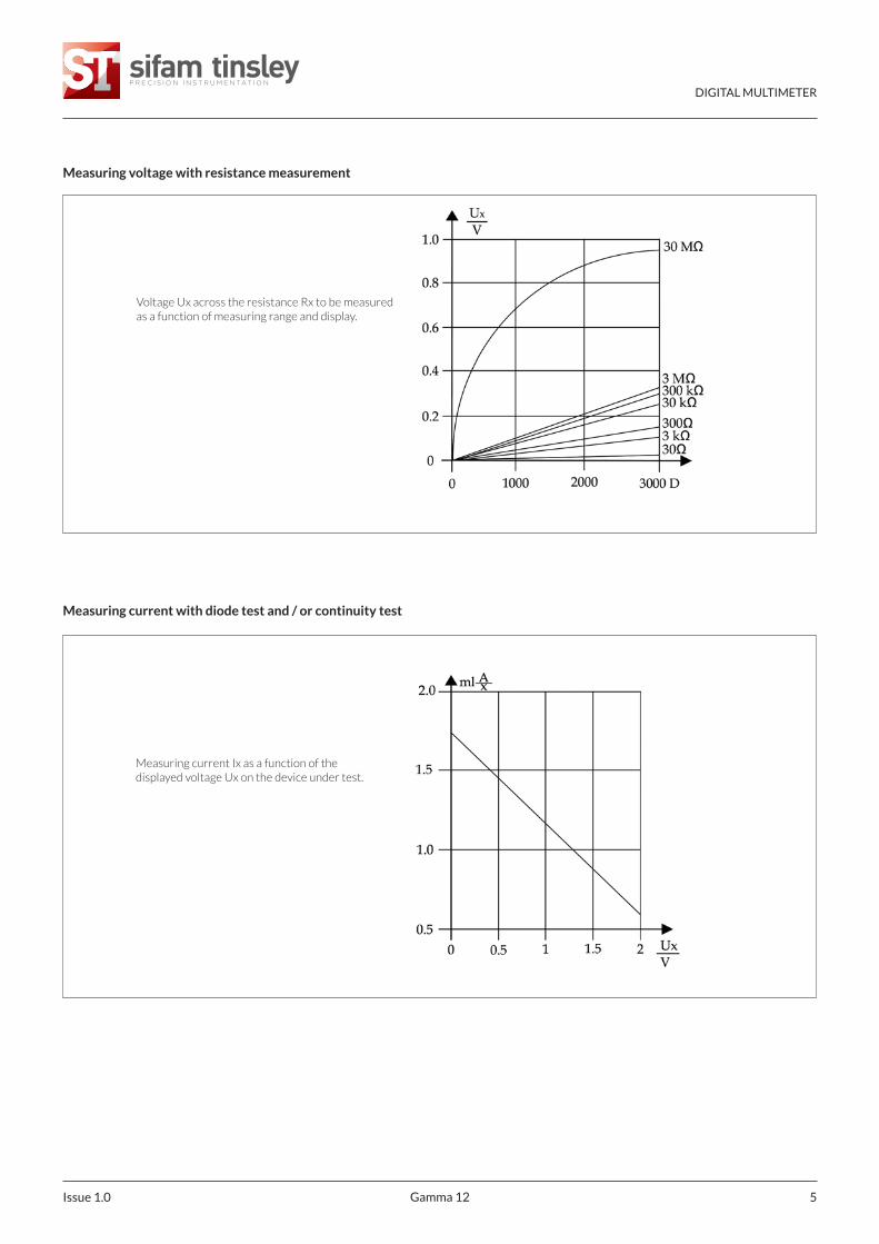
Measuring voltage with resistance measurement
Voltage Ux across the resistance Rx to be measuredas a function of measuring range and display.
Measuring current with diode test and / or continuity test
Measuring current Ix as a function of thedisplayed voltage Ux on the device under test.
DIGITAL MULTIMETER
Gamma 12 Issue 1.06
Influence quantities and variations
Influence Influence Measured quantity / Variation 1)quantity range measuring range ± (...% of meas. val. ±...digits)
30/300 mV 1.0 + 13... 300 V 0.1 + 11000 V 0.1 + 1V~ 0.3 + 2300 µ A 2 ... 0.15 + 1300 mA3A / 10 (16) A
0 °C... + 21 °C A~ 0.75 + 3Temperature and 30 Ω 0.15 + 2
+25 °C... + 40 °C 300 Ω 0.15 + 23 k ...3 MΩ 0.1 + 130 MΩ 0.6 + 130 nF 2) ... 3µF 0.5 + 230 µF 2.0 + 2Hz 0.5 + 1% ± 5 D-200... + 20 0 °C 0.5 K + 2+ 200... + 8 50 °C 0.5 + 2
15 Hz... < 30 Hz 1.0 + 330 Hz... < 45 Hz 0.5 + 3> 65 Hz... 400Hz 3...300 V~ 0.5 + 3
Frequency of the > 400 Hz... 1 kHz 1.0 + 3measured quantity > 1kHz... 20 kHz 2.0 + 3
15 Hz... < 30 Hz 1.0 + 330 Hz... < 45 Hz 1000 V~ 0.5 + 3> 65 Hz... 1kHz 2.0 + 315 Hz... < 30 Hz 1.0 + 330 Hz... <45 Hz A~ 0.5 + 3> 65 Hz...1kHz 3.0 + 3
± 1%of rdg.± 3%of rdg.
V ~ 4) , A~ 4)Crestfactor CF
1 ...3> 3 ...5
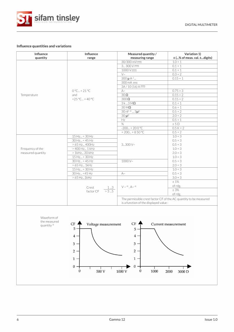
The permissible crest factor CF of the AC quantity to be measuredis a function of the displayed value :
Waveform ofthe measuredquantity 3)
DIGITAL MULTIMETER
Gamma 12 7Issue 1.0
Influence quantities and variations
Influence Influence Measured quantity / Variation 1)quantity range measuring range ± (...% of meas. val. ±...digits)
V + 2 DV~ + 4 DA + 4 D
Battery voltage 5) ... < 7.9 V A~ + 6 D> 8.1 V... 10.0 V 30Ω / 300Ω / ºC + 4 D
3 kΩ ... 30 MΩ + 3 DnF, µF + 1 DHz + 1 D% + 1 DV
75 % ARelative humidity 3 days Ω 1x Intrinsic error
Meter off FHz%
DATA °C ±1 DMIN / MAX V , A ± 2 D~ ~
1) With temperature; Error data is per 10 K change in temperature. With frequency; Error data is valid from a display of 300 digits.
2) With zero setting
3) With unknown waveform (crest factor CF > 2), the measurement must be made with manual range selection.
4) Except for sinusoidal waveform
5) From the time the symbol “ “ appears.

DIGITAL MULTIMETER
Gamma 12 Issue 1.08
Ordering Information
GM20 - 6NB4000000000GAMMA 12
Gamma 12 TRMS BacklitGM20 - 6FB4000000000 Gamma 12 TRMS Fine Tip TRMS Backlit
1 Warner DriveSpringwood Industrial EstateBraintree, EssexCM7 2YW
Tel: 01376 335271E-mail: [email protected]
Sifam Tinsley Instrumentation Ltd
www.sifamtinsley.co.uk
Contact
Operating controls