Embed Size (px)
DESCRIPTION
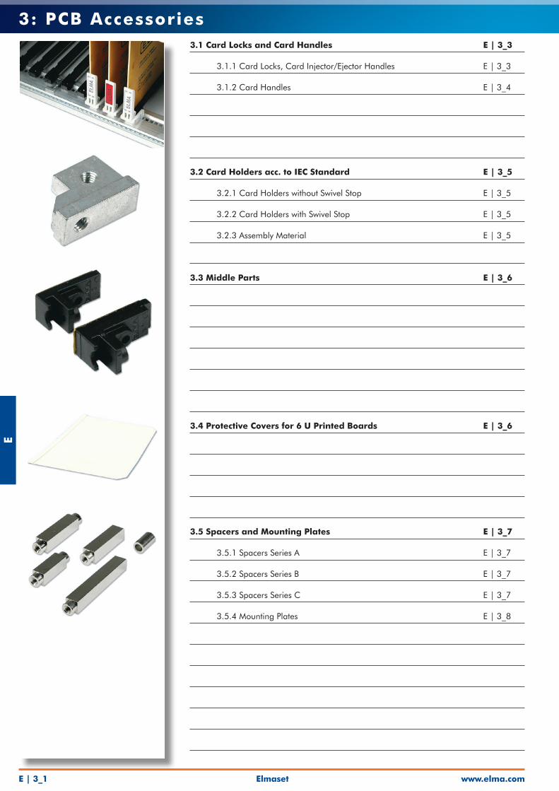
•Card Locks and Card Handles •Card Holders •Middle Parts and Protective Covers •Spacers and Mounting Plates •Covering Caps and Mounting Brackets
Citation preview
www.elma.comElmasetE | 3_1
E3: PCB Accessories
3.1 Card Locks and Card Handles E | 3_3
3.1.1 Card Locks, Card Injector/Ejector Handles E | 3_3
3.1.2 Card Handles E | 3_4
3.2 Card Holders acc. to IEC Standard E | 3_5
3.2.1 Card Holders without Swivel Stop E | 3_5
3.2.2 Card Holders with Swivel Stop E | 3_5
3.2.3 Assembly Material E | 3_5
3.3 Middle Parts E | 3_6
3.4 Protective Covers for 6 U Printed Boards E | 3_6
3.5 Spacers and Mounting Plates E | 3_7
3.5.1 Spacers Series A E | 3_7
3.5.2 Spacers Series B E | 3_7
3.5.3 Spacers Series C E | 3_7
3.5.4 Mounting Plates E | 3_8

Elmasetwww.elma.com E | 3_2
E3: PCB Accessories
3.6 Hexagonal Spacers M3 Thread E | 3_8
3.7 Covering Caps E | 3_8
3.8 Mounting Brackets E | 3_9
www.elma.comElmasetE | 3_3
E3: PCB Accessories
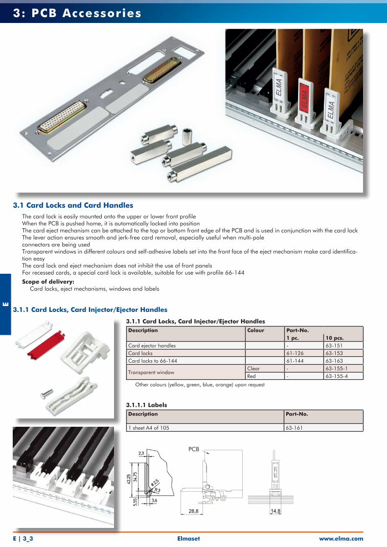
3.1.1 Card Locks, Card Injector/Ejector Handles Description Colour Part-No.
1 pc. 10 pcs.Card ejector handles - 63-151Card locks 61-126 63-153Card locks to 66-144 61-144 63-163
Transparent windowClear - 63-155-1Red - 63-155-4
• Other colours (yellow, green, blue, orange) upon request
3.1.1.1 LabelsDescription Part-No.
1 sheet A4 of 105 63-161
3.1 Card Locks and Card Handles• The card lock is easily mounted onto the upper or lower front profile• When the PCB is pushed home, it is automatically locked into position• The card eject mechanism can be attached to the top or bottom front edge of the PCB and is used in conjunction with the card lock• The lever action ensures smooth and jerk-free card removal, especially useful when multi-pole connectors are being used• Transparent windows in different colours and self-adhesive labels set into the front face of the eject mechanism make card identifica-
tion easy• The card lock and eject mechanism does not inhibit the use of front panels• For recessed cards, a special card lock is available, suitable for use with profile 66-144
• Scope of delivery: • Card locks, eject mechanisms, windows and labels
28,8 14,8
PCB
3.1.1 Card Locks, Card Injector/Ejector Handles
Elmasetwww.elma.com E | 3_4
E3: PCB Accessories
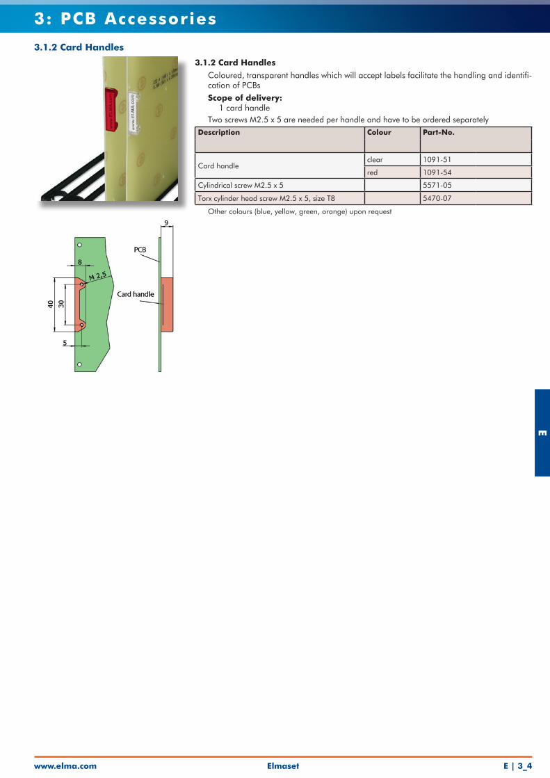
3.1.2 Card Handles
• Coloured, transparent handles which will accept labels facilitate the handling and identifi-cation of PCBs
• Scope of delivery: • 1 card handle• Two screws M2.5 x 5 are needed per handle and have to be ordered separatelyDescription Colour Part-No.
Card handleclear 1091-51
red 1091-54
Cylindrical screw M2.5 x 5 5571-05
Torx cylinder head screw M2.5 x 5, size T8 5470-07
• Other colours (blue, yellow, green, orange) upon request
3.1.2 Card Handles
www.elma.comElmasetE | 3_5
E3: PCB Accessories
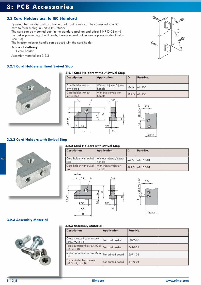
3.2 Card Holders acc. to IEC Standard• By using the zinc die-cast card holder, flat front panels can be connected to a PC
card to form a plug-in unit to IEC 60297• The card can be mounted both in the standard position and offset 1 HP (5.08 mm)• For better positioning of 6 U cards, there is a card holder centre piece made of nylon
(see 3.3)• The injector-/ejector handle can be used with the card holder
• Scope of delivery: • 1 card holder
• Assembly material see 3.2.3
3.2.1 Card Holders without Swivel StopDescription Application D Part-No.
Card holder without swivel stop
Without injector/ejector handle
M2.5 61-156
Card holder without swivel stop
With injector/ejector handle
Ø 2.5 61-155
3.2.2 Card Holders with Swivel StopDescription Application D Part-No.
Card holder with swivel stop
Without injector/ejector handle
M2.5 61-156-01
Card holder with swivel stop
With injector/ejector handle
Ø 2.5 61-155-01
3.2.3 Assembly MaterialDescription Application Part-No.
Cross recessed countersunk screw M2.5 x 8
For card holder 5322-08
Torx countersunk screw M2.5 x 8, size T8
For card holder 5470-21
Slotted pan head screw M2.5 x 6
For printed board 5571-06
Torx cylinder head screw M2.5 x 6, size T8
For printed board 5470-04
3.2.1 Card Holders without Swivel Stop
3.2.2 Card Holders with Swivel Stop
3.2.3 Assembly Material
Elmasetwww.elma.com E | 3_6
E3: PCB Accessories
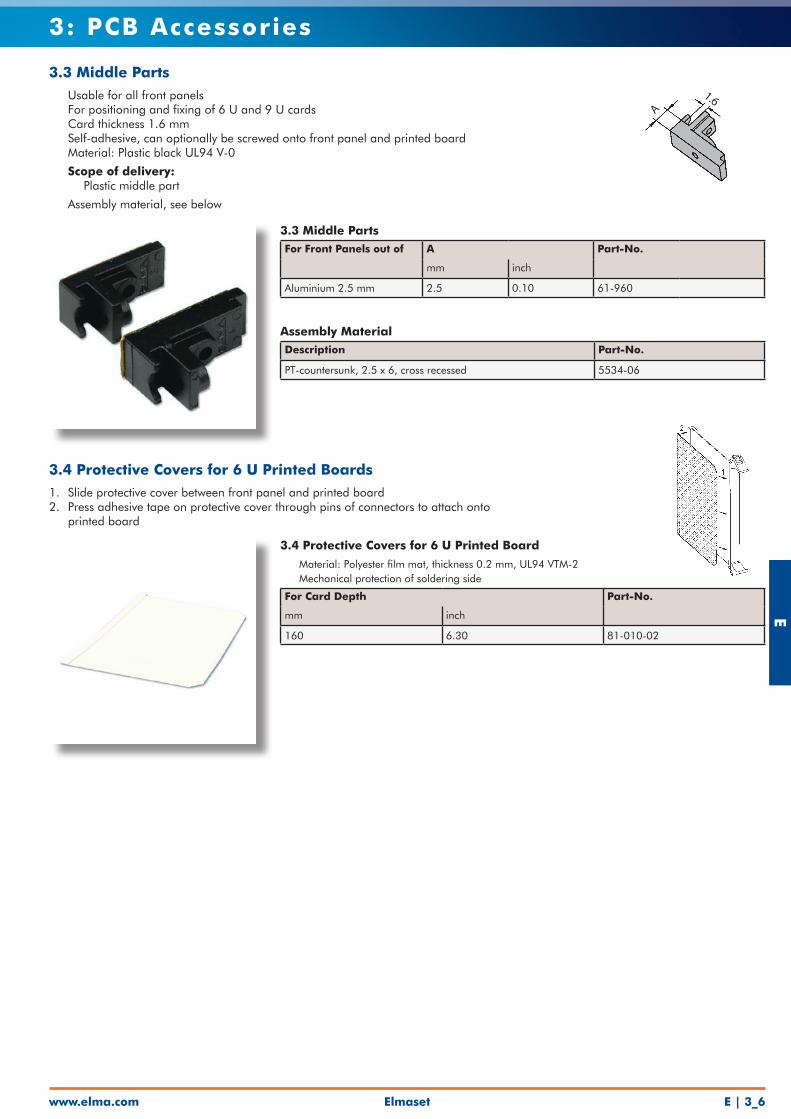
3.3 Middle Parts• Usable for all front panels• For positioning and fixing of 6 U and 9 U cards• Card thickness 1.6 mm• Self-adhesive, can optionally be screwed onto front panel and printed board• Material: Plastic black UL94 V-0
• Scope of delivery: • Plastic middle part
• Assembly material, see below
3.3 Middle PartsFor Front Panels out of A Part-No.
mm inch
Aluminium 2.5 mm 2.5 0.10 61-960
Assembly MaterialDescription Part-No.
PT-countersunk, 2.5 x 6, cross recessed 5534-06
3.4 Protective Covers for 6 U Printed Boards1. Slide protective cover between front panel and printed board2. Press adhesive tape on protective cover through pins of connectors to attach onto
printed board
3.4 Protective Covers for 6 U Printed Board
• Material: Polyester film mat, thickness 0.2 mm, UL94 VTM-2• Mechanical protection of soldering side
For Card Depth Part-No.
mm inch
160 6.30 81-010-02A
1.6
www.elma.comElmasetE | 3_7
E3: PCB Accessories
3.5.1 Spacers Series A• Use between PCB mounting lugs and PCBs• Gives 5.08 mm pitch
Length L Part-No. mm inch
10.16 0.40 61-300
15.24 0.60 61-301
20.32 0.80 61-302Other lengths available on request
3.5.2 Spacers Series B• Use between two PCBs• Gives 5.08 mm pitch
Length L Part-No. mm inch
13.64 0.53 61-320
18.72 0.73 61-321
23.80 0.93 61-322
3.5.3 Spacers Series C• Use between a PCB with connector and a second PCB
Length L Part-No. mm inch
7.64 0.30 61-340
A B C
A (n-6
) x
5,0
8
1,6
(n-6
) x
5,0
813,6
4
X x 5,08 -1,6(X-1) x 5,08
X x
5,08
11,0
4n x
5,0
8
n * 5.08 = theoretical width of front panelx * 5.08 = distance of printed PCBsn = multiple of the 5.08 pitch of the selected front panelx = selected multiple of the 5.08 pitch for the distance of printed PCBs
Length L
Series A
Length L
Series B
Series C
3.5 Spacers and Mounting Plates• Four-sided, nickel-plated brass spacers with M2.5 internal threads at both ends• Using these spacers, additional PCBs may be mounted at a horizontal pitch of 5.08 mm• Mounting plate is 1.5 mm galvanised steel with mounting holes corresponding to
PCBs conforming to IEC 60297

Elmasetwww.elma.com E | 3_8
E3: PCB Accessories
5.5 6.5
Length L
5.5
M3
M3
3.5.4 Mounting Plates• Dimensions identical to eurocard dimensions• 1.5 mm galvanized sheet steel
• Scope of delivery: • 1 mounting plate• Assembly material, see below
Height Dimensions Part-No.3 U 100 x 160 mm (3.93" x 6.29") 61-3506 U 233.35 x 160 mm (9.18" x 6.29") 61-351
Assembly MaterialDescription Part-No.
Screws recessed M2.5 x 5 5571-05
3.6 Hexagonal Spacers M3 Thread• Galvanized steel• Ideal for use as supports or spacers
• Scope of delivery: • 1 spacer
3.6 Hexagonal Spacers, M3 ThreadLength L Part-No. mm inch10 0.39 1922-0115 0.59 1922-0230 1.18 1922-0540 1.57 1922-07
Length L Part-No. mm inch8.5 0.33 1923-0113.5 0.53 1923-02
3.7 Covering Caps• The caps, fit openings for D-Sub connectors and can be fitted without special tools• Material: ABS grey UL94 HB
• Scope of delivery: • Plastic covering caps
3.6 Covering CapsOpening A B C D E Part-No.
mm mm mm mm mmDB9 9-poles 25.0 20.5 11.4 32.0 14.0 61-920DB15 15-poles 33.3 28.8 11.4 40.3 14.0 61-921DB25 25-poles 47.0 42.5 11.4 54.0 14.0 61-922DB37 37-poles 63.5 59.1 11.4 70.5 14.0 61-923
1922-0x1923-0x
6 6
Length L
M3
M3
5.5
3.5.4 Mounting Plates
www.elma.comElmasetE | 3_9
E3: PCB Accessories
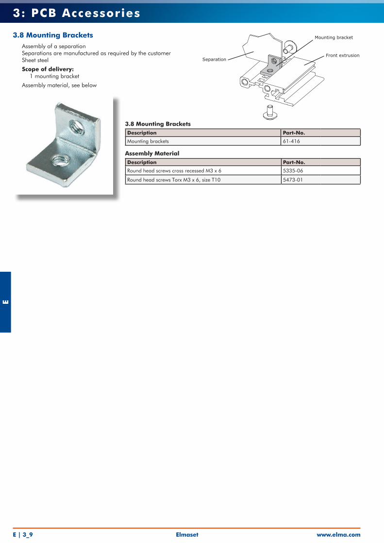
3.8 Mounting Brackets• Assembly of a separation• Separations are manufactured as required by the customer• Sheet steel
• Scope of delivery: • 1 mounting bracket
• Assembly material, see below
3.8 Mounting BracketsDescription Part-No.
Mounting brackets 61-416
Assembly MaterialDescription Part-No.
Round head screws cross recessed M3 x 6 5335-06
Round head screws Torx M3 x 6, size T10 5473-01
Mounting bracket
SeparationFront extrusion

4: Front Panel Elements