Embed Size (px)
Citation preview
Features
Application
QSFP28-SR4-100G
Optical Communication System
1
Datasheet
• 100GBASE-SR4 100G Ethernet
QSFP28 100GBASE-SR4 850nm 100m Transceiver
• Hot Pluggable QSFP28 form factor
• Supports 103.1Gb/s aggregate bit
rate
• Maximum link length of 100m on
OM4 Multimode Fiber (MMF)
• Single MPO12 receptacle
• Single 3.3V power supply
• Power dissipation <3.5W
• 4x25Gb/s 850mm VCSEL-based
transmitter
• 4x25G electrical interface
• Commercial operating case
temperature range: 0°C to 70°C
• I2C management interface
• RoHS-6 compliant
Optical Communication System
2
Datasheet
Description
Product Specifications
I. General Product Characteristics
100G QSFP28 transceiver modules are designed for use in100 Gigabit Ethernet links over multimode fiber. They are compliant with the QSFP28 MSA and IEEE 802.3bm 100GBASE-SR4 and CAUI-4. Digital diagnostics functions are available via the I2C interface, as specified by the QSFP28 MSA1and Finisar Application Note AN-2141. The transceiver is RoHS-6 compliant per Directive2011/65/EU.
Parameter Symbol Min Type Max Units Ref.
Bit Rate (all wavelengths combined)
BR 103.1 Gb/s 1
Bit Error Ratio BER 5x10⁻⁵ 2
OM3 MMF Lmax1 70 m 3
OM4 MMF Lmax2 100 m 3
Notes: 1.Supports 100GBASE-SR4 per IEEE 802.3bm. 2. Tested with a 231-1 PRBS . 3. Requires FEC on the host to support maximum distance, per 100GBASE-SR4.
Page 3 of 4 +86 (755) 8300 3611 [email protected] www.fiberstore.com
Copyright © 2009-2015 Fiberstore
+86 (755) 8300 3611 [email protected] www.fiberstore.com
Copyright © 2009-2015 Fiberstore
+86 (755) 8300 3611 [email protected] www.fiberstore.com [email protected] FSCOM
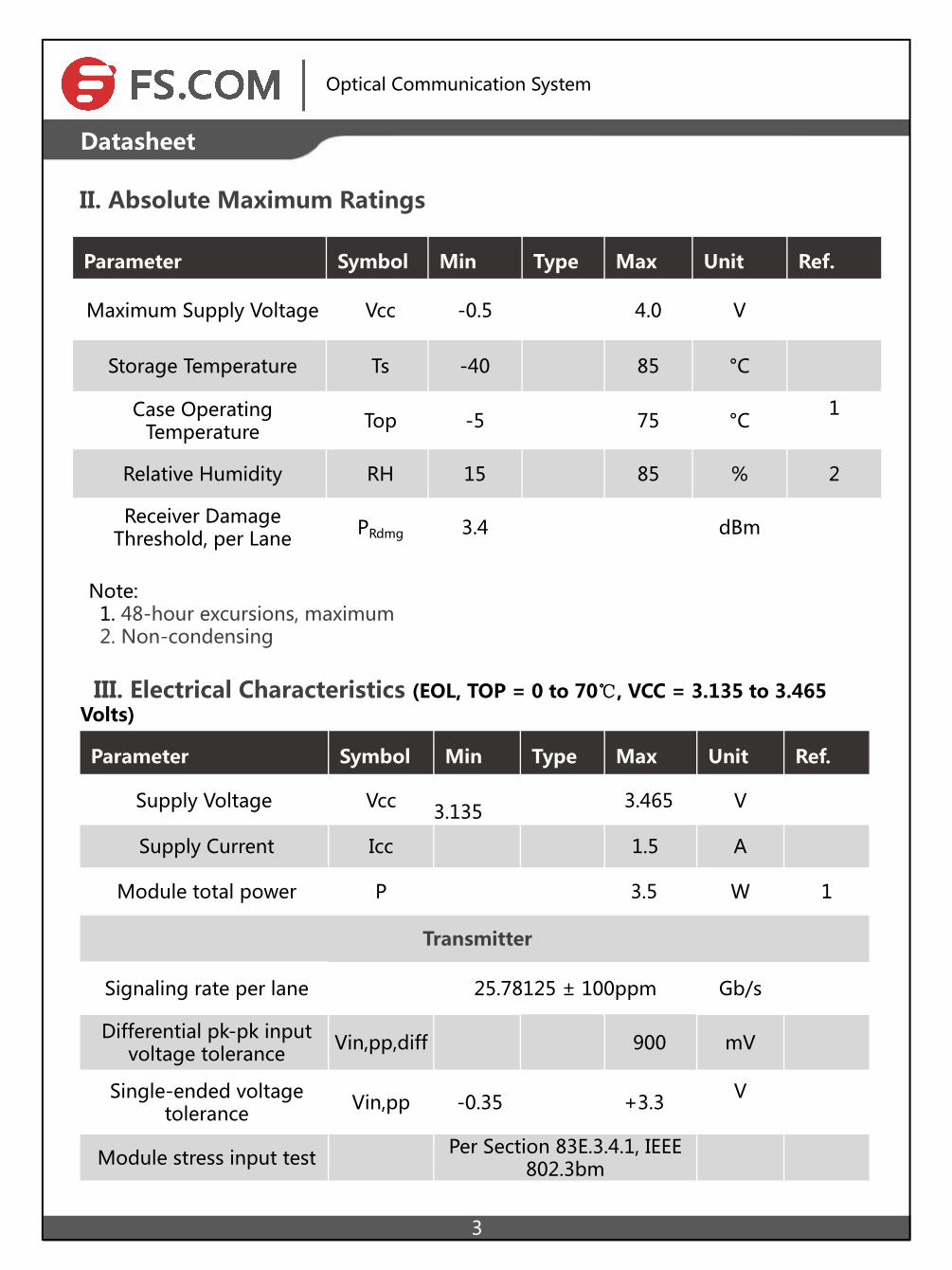
II. Absolute Maximum Ratings
Optical Communication System
3
Datasheet
Parameter Symbol Min Type Max Unit Ref.
Maximum Supply Voltage Vcc -0.5 4.0 V
Storage Temperature Ts -40 85 °C
Case Operating Temperature Top -5 75 °C
1
Relative Humidity RH 15 85 % 2
Receiver Damage Threshold, per Lane PRdmg 3.4 dBm
Note: 1. 48-hour excursions, maximum 2. Non-condensing
III. Electrical Characteristics (EOL, TOP = 0 to 70℃, VCC = 3.135 to 3.465 Volts)
Parameter Symbol Min Type Max Unit Ref.
Supply Voltage Vcc 3.135 3.465 V
Supply Current Icc 1.5 A
Module total power P 3.5 W 1
Transmitter
Signaling rate per lane 25.78125 ± 100ppm Gb/s
Differential pk-pk input voltage tolerance Vin,pp,diff 900 mV
Single-ended voltage tolerance Vin,pp -0.35 +3.3 V
Module stress input test Per Section 83E.3.4.1, IEEE802.3bm
+86 (755) 8300 3611 [email protected] www.fiberstore.com Page 4 of 4
Copyright © 2009-2015 Fiberstore
+86 (755) 8300 3611 [email protected] www.fiberstore.com Page 4 of 6
Copyright © 2009-2015 Fiberstore
+86 (755) 8300 3611 [email protected] www.fiberstore.com
[email protected] FS.COM
Optical Communication System
4
Datasheet
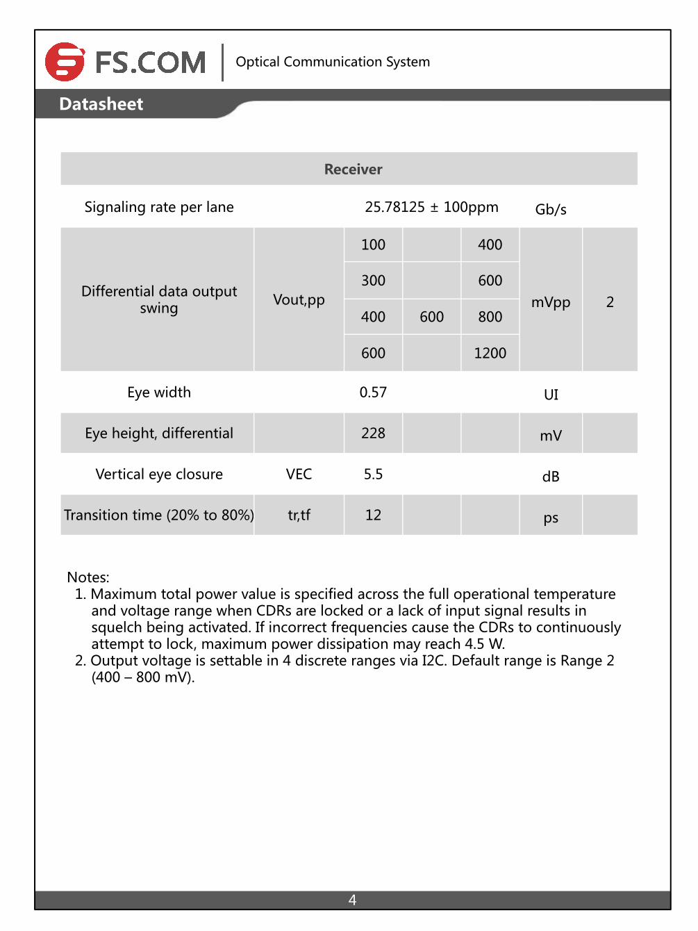
Receiver
Signaling rate per lane 25.78125 ± 100ppm Gb/s
Differential data output swing Vout,pp
100 400
mVpp 2300 600
400 600 800
600 1200
Eye width 0.57 UI
Eye height, differential 228 mV
Vertical eye closure VEC 5.5 dB
Transition time (20% to 80%) tr,tf 12 ps
Notes: 1. Maximum total power value is specified across the full operational temperature and voltage range when CDRs are locked or a lack of input signal results in squelch being activated. If incorrect frequencies cause the CDRs to continuously attempt to lock, maximum power dissipation may reach 4.5 W. 2. Output voltage is settable in 4 discrete ranges via I2C. Default range is Range 2 (400 – 800 mV).
Optical Communication System
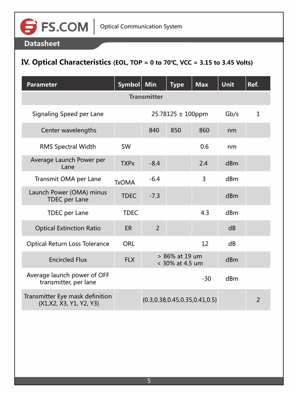
IV. Optical Characteristics (EOL, TOP = 0 to 70℃, VCC = 3.15 to 3.45 Volts)
5
Datasheet
Parameter Symbol Min Type Max Unit Ref.
Transmitter
Signaling Speed per Lane 25.78125 ± 100ppm Gb/s 1
Center wavelengths 840 850 860 nm
RMS Spectral Width SW 0.6 nm
Average Launch Power per Lane TXPx -8.4 2.4 dBm
Transmit OMA per Lane TxOMA -6.4 3 dBm
Launch Power (OMA) minus TDEC per Lane TDEC -7.3 dBm
TDEC per Lane TDEC 4.3 dBm
Optical Extinction Ratio ER 2 dB
Optical Return Loss Tolerance ORL 12 dB
Encircled Flux FLX > 86% at 19 um< 30% at 4.5 um dBm
Average launch power of OFF transmitter, per lane -30 dBm
Transmitter Eye mask definition {X1,X2, X3, Y1, Y2, Y3} {0.3,0.38,0.45,0.35,0.41,0.5} 2
Optical Communication System
6
Datasheet
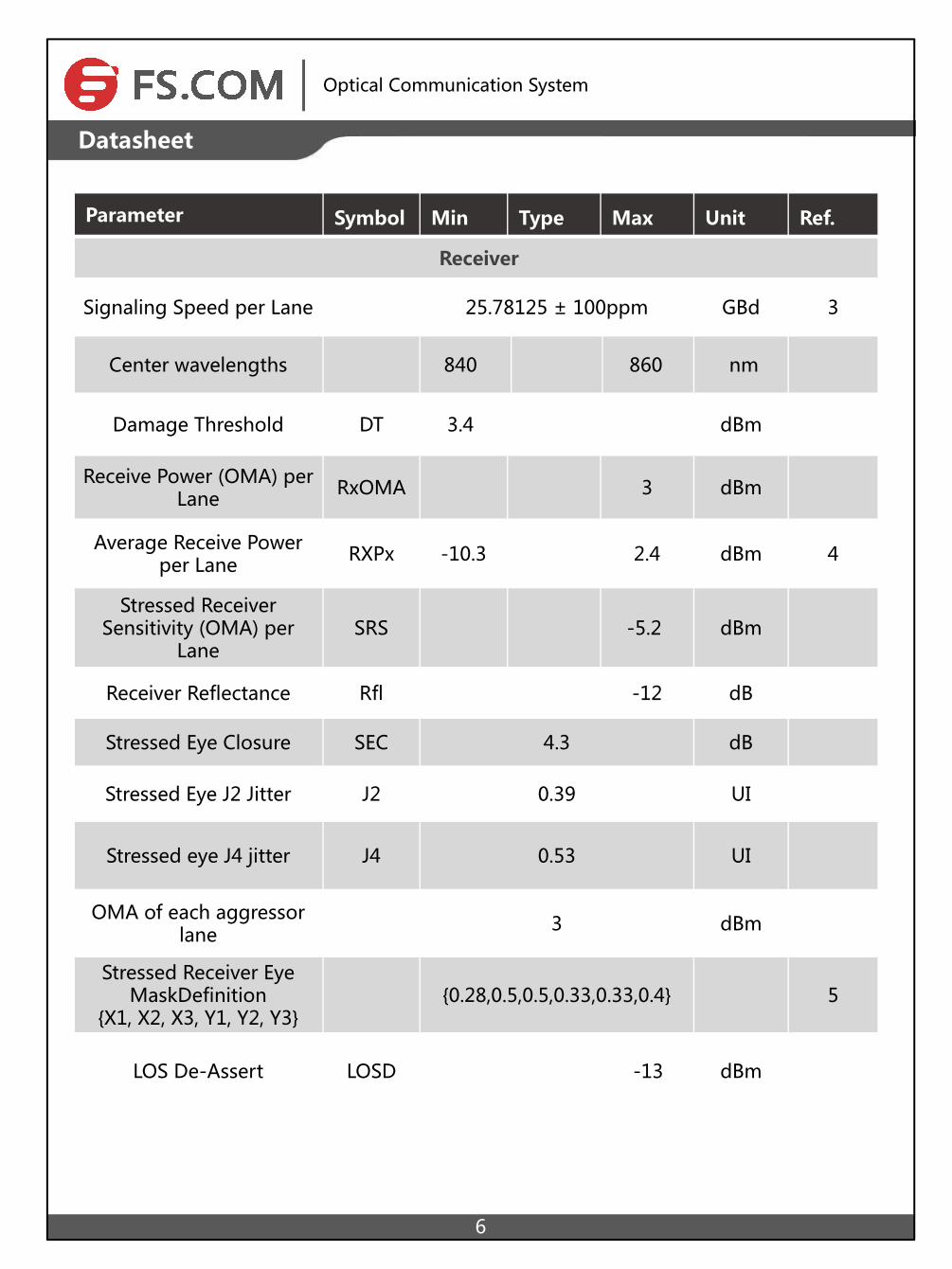
Parameter Symbol Min Type Max Unit Ref.
Receiver
Signaling Speed per Lane 25.78125 ± 100ppm GBd 3
Center wavelengths 840 860 nm
Damage Threshold DT 3.4 dBm
Receive Power (OMA) per Lane RxOMA 3 dBm
Average Receive Power per Lane RXPx -10.3 2.4 dBm 4
Stressed Receiver Sensitivity (OMA) per
LaneSRS -5.2 dBm
Receiver Reflectance Rfl -12 dB
Stressed Eye Closure SEC 4.3 dB
Stressed Eye J2 Jitter J2 0.39 UI
Stressed eye J4 jitter J4 0.53 UI
OMA of each aggressor lane 3 dBm
Stressed Receiver Eye MaskDefinition
{X1, X2, X3, Y1, Y2, Y3}{0.28,0.5,0.5,0.33,0.33,0.4} 5
LOS De-Assert LOSD -13 dBm
Optical Communication System
7
Datasheet
LOS Assert LOSA -30 dBm
LOS Hysteresis 0.5 2 dB
Notes: 1. Transmitter consists of 4 lasers operating at a maximum speed of 25.78125Gb/s ±100ppm each. 2. Hit Ratio 1.5 x 10⁻³ hits/sample. 3. Receiver consists of 4 photodetectors operating at a maximum speed of 25.78125Gb/s ±100ppm each. 4. Minimum value is informative only and not the principal indicator of signal strength. 5. Hit Ratio 5 x 10⁻⁵ hits/sample.
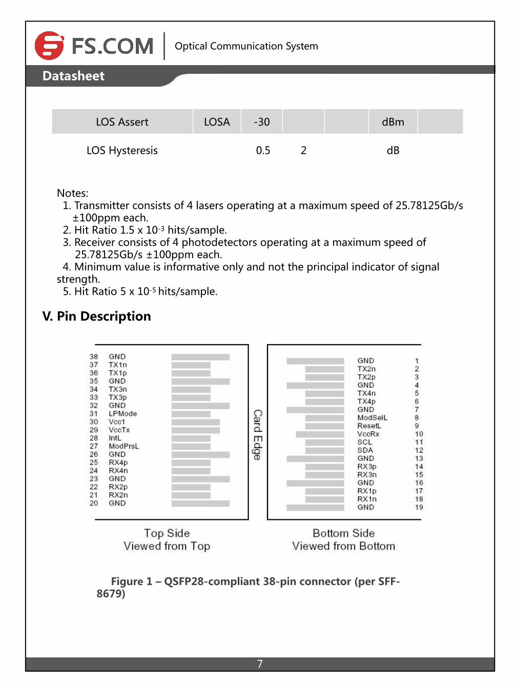
V. Pin Description
Figure 1 – QSFP28-compliant 38-pin connector (per SFF-8679)
Optical Communication System
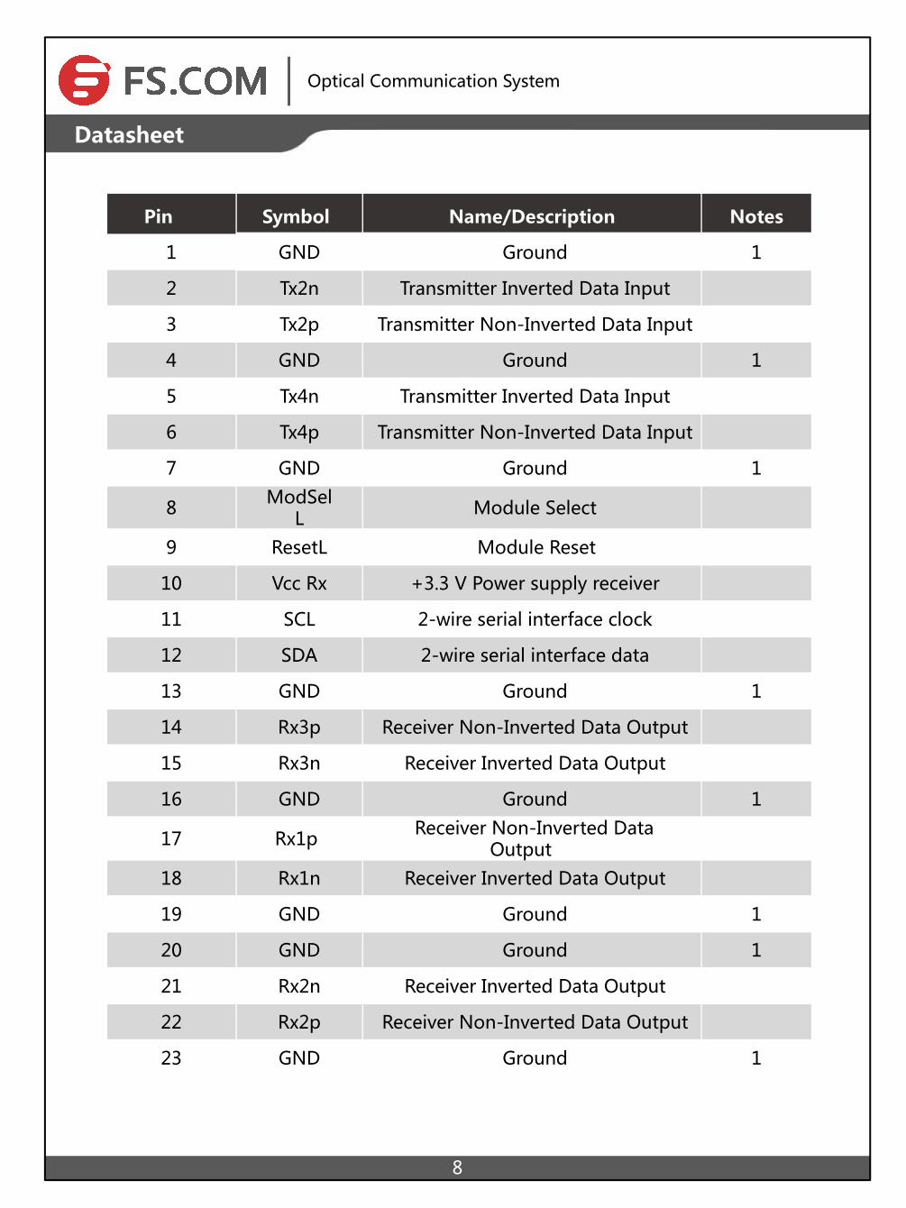
Pin Symbol Name/Description Notes
1 GND Ground 1
2 Tx2n Transmitter Inverted Data Input
3 Tx2p Transmitter Non-Inverted Data Input
4 GND Ground 1
5 Tx4n Transmitter Inverted Data Input
6 Tx4p Transmitter Non-Inverted Data Input
7 GND Ground 1
8 ModSelL Module Select
9 ResetL Module Reset
10 Vcc Rx +3.3 V Power supply receiver
11 SCL 2-wire serial interface clock
12 SDA 2-wire serial interface data
13 GND Ground 1
14 Rx3p Receiver Non-Inverted Data Output
15 Rx3n Receiver Inverted Data Output
16 GND Ground 1
17 Rx1p Receiver Non-Inverted Data Output
18 Rx1n Receiver Inverted Data Output
19 GND Ground 1
20 GND Ground 1
21 Rx2n Receiver Inverted Data Output
22 Rx2p Receiver Non-Inverted Data Output
23 GND Ground 1
8
Datasheet
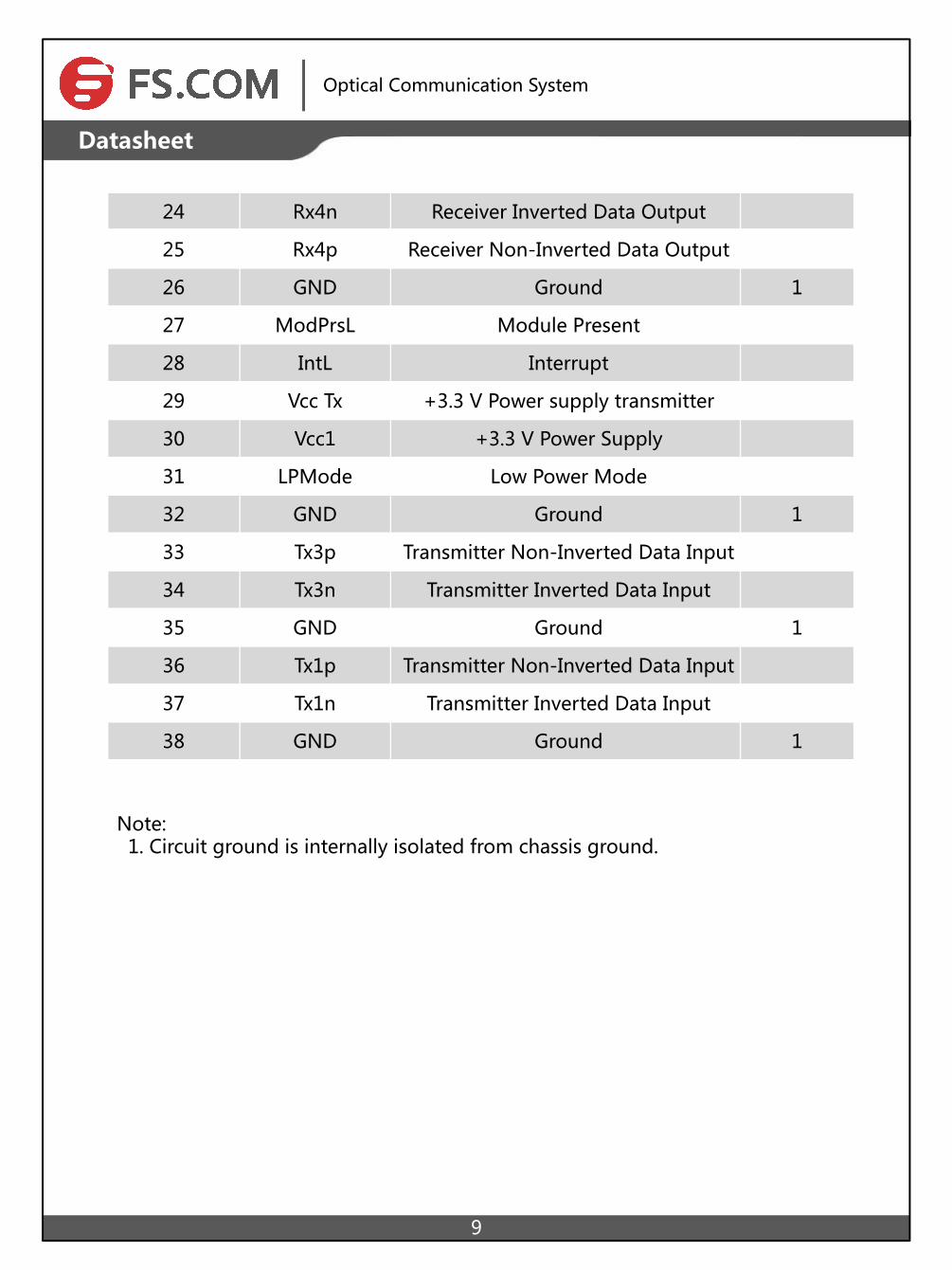
24 Rx4n Receiver Inverted Data Output
25 Rx4p Receiver Non-Inverted Data Output
26 GND Ground 1
27 ModPrsL Module Present
28 IntL Interrupt
29 Vcc Tx +3.3 V Power supply transmitter
30 Vcc1 +3.3 V Power Supply
31 LPMode Low Power Mode
32 GND Ground 1
33 Tx3p Transmitter Non-Inverted Data Input
34 Tx3n Transmitter Inverted Data Input
35 GND Ground 1
36 Tx1p Transmitter Non-Inverted Data Input
37 Tx1n Transmitter Inverted Data Input
38 GND Ground 1
9
Optical Communication System
DatasheetDatasheet
Note: 1. Circuit ground is internally isolated from chassis ground.
10
Optical Communication System
Datasheet
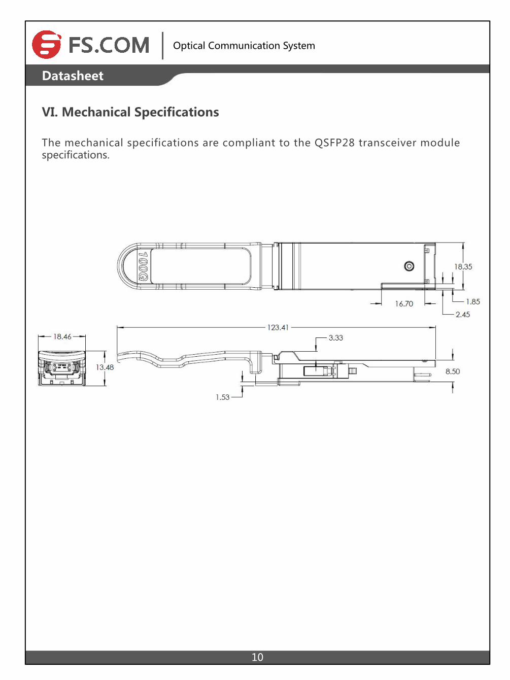
VI. Mechanical Specifications
The mechanical specifications are compliant to the QSFP28 transceiver module specifications.
+86 (755) 8300 3611 [email protected] www.
Copyright © 2009-2015 Fiberstore
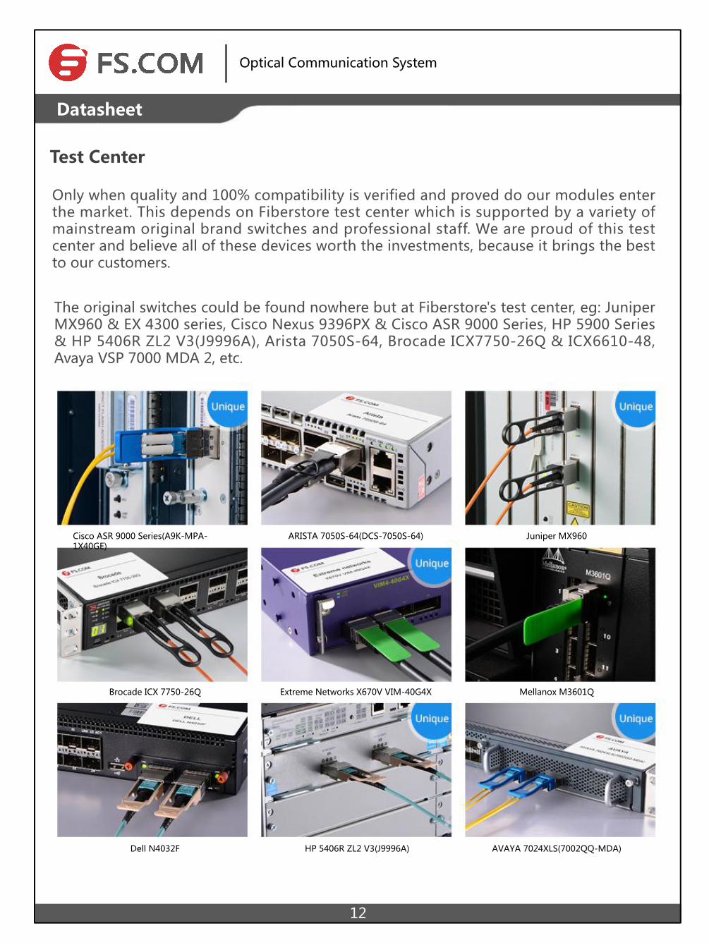
Test Center
Copyright © 2009-2015 Fiberstore
Only when quality and 100% compatibility is verified and proved do our modules enter the market. This depends on Fiberstore test center which is supported by a variety of mainstream original brand switches and professional staff. We are proud of this test center and believe all of these devices worth the investments, because it brings the best to our customers.
The original switches could be found nowhere but at Fiberstore's test center, eg: Juniper MX960 & EX 4300 series, Cisco Nexus 9396PX & Cisco ASR 9000 Series, HP 5900 Series & HP 5406R ZL2 V3(J9996A), Arista 7050S-64, Brocade ICX7750-26Q & ICX6610-48, Avaya VSP 7000 MDA 2, etc.
Optical Communication System
12
DatasheetDatasheet
Cisco ASR 9000 Series(A9K-MPA-1X40GE)
ARISTA 7050S-64(DCS-7050S-64) Juniper MX960
Brocade ICX 7750-26Q Extreme Networks X670V VIM-40G4X Mellanox M3601Q
Dell N4032F HP 5406R ZL2 V3(J9996A) AVAYA 7024XLS(7002QQ-MDA)

Test Assured Program
Our smart data system allows effective product management and quality control according to the unique serial number, properly tracing the order, shipment and every part.
Our in-house coding facility programs all of our parts to standard OEM specs for compatibility on all major vendors and systems such as Cisco, Juniper, Brocade, HP, Dell, Arista and so on.
Fiberstore truly understands the value of compatibility and interoperability to each optics. Every module Fiberstore provides must run through programming and an extensive series of platform diagnostic tests to prove its performance and compatibility. In our test center, we care of every detail from staff to facilities—professionally trained staff, advanced test facilities and comprehensive original-brand switches, to ensure our customers to receive the optics with superior quality.
With a comprehensive line of original-brand switches, we can recreate an environment and test each optics in practical application to ensure quality and distance.
The last test assured step to ensure our products to be shipped with perfect package.
Optical Communication System
12
Datasheet
Copyright © 2009-2015 Fiberstore
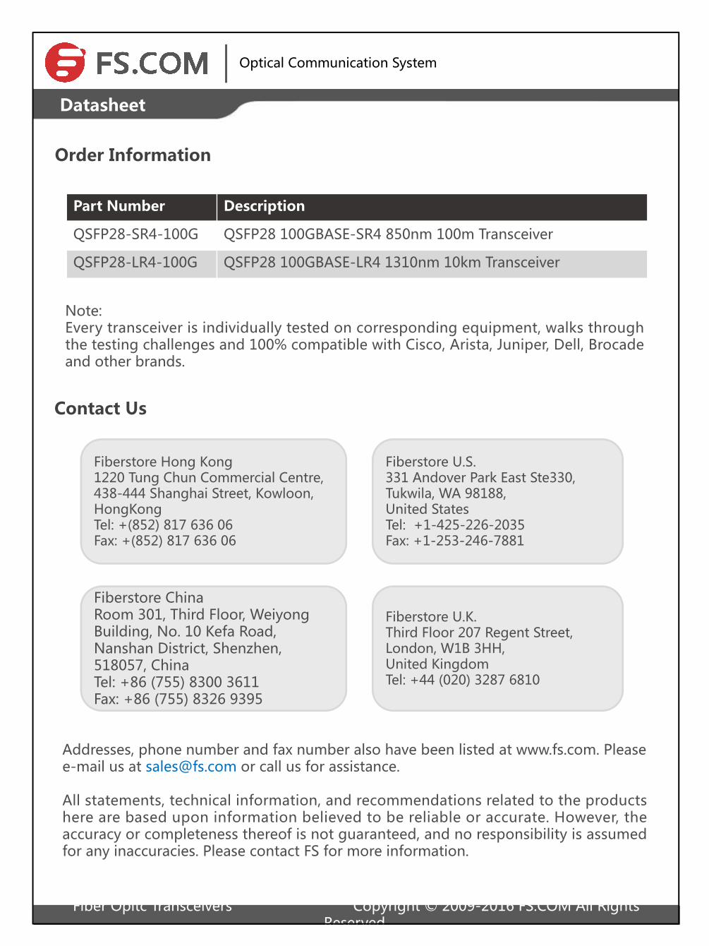
Order Information
Copyright © 2009-2015 Fiberstore
Note: Every transceiver is individually tested on corresponding equipment, walks through the testing challenges and 100% compatible with Cisco, Arista, Juniper, Dell, Brocade and other brands.
13
Optical Communication System
Part Number Description
QSFP28-SR4-100G QSFP28 100GBASE-SR4 850nm 100m Transceiver
QSFP28-LR4-100G QSFP28 100GBASE-LR4 1310nm 10km Transceiver
Datasheet
Contact Us
Fiberstore U.S. 331 Andover Park East Ste330, Tukwila, WA 98188, United StatesTel: +1-425-226-2035Fax: +1-253-246-7881
Fiberstore Hong Kong1220 Tung Chun Commercial Centre, 438-444 Shanghai Street, Kowloon, HongKongTel: +(852) 817 636 06Fax: +(852) 817 636 06
Fiberstore U.K.Third Floor 207 Regent Street, London, W1B 3HH, United KingdomTel: +44 (020) 3287 6810
Addresses, phone number and fax number also have been listed at www.fs.com. Please e-mail us at [email protected] or call us for assistance.
All statements, technical information, and recommendations related to the products here are based upon information believed to be reliable or accurate. However, the accuracy or completeness thereof is not guaranteed, and no responsibility is assumed for any inaccuracies. Please contact FS for more information.
Fiber Opitc Transceivers Copyright © 2009-2016 FS.COM All Rights Reserved.
Fiberstore ChinaRoom 301, Third Floor, Weiyong Building, No. 10 Kefa Road, Nanshan District, Shenzhen, 518057, ChinaTel: +86 (755) 8300 3611Fax: +86 (755) 8326 9395