Embed Size (px)
Citation preview
www.sensirion.com / D1 Version 0.9 – September 2018 1/25
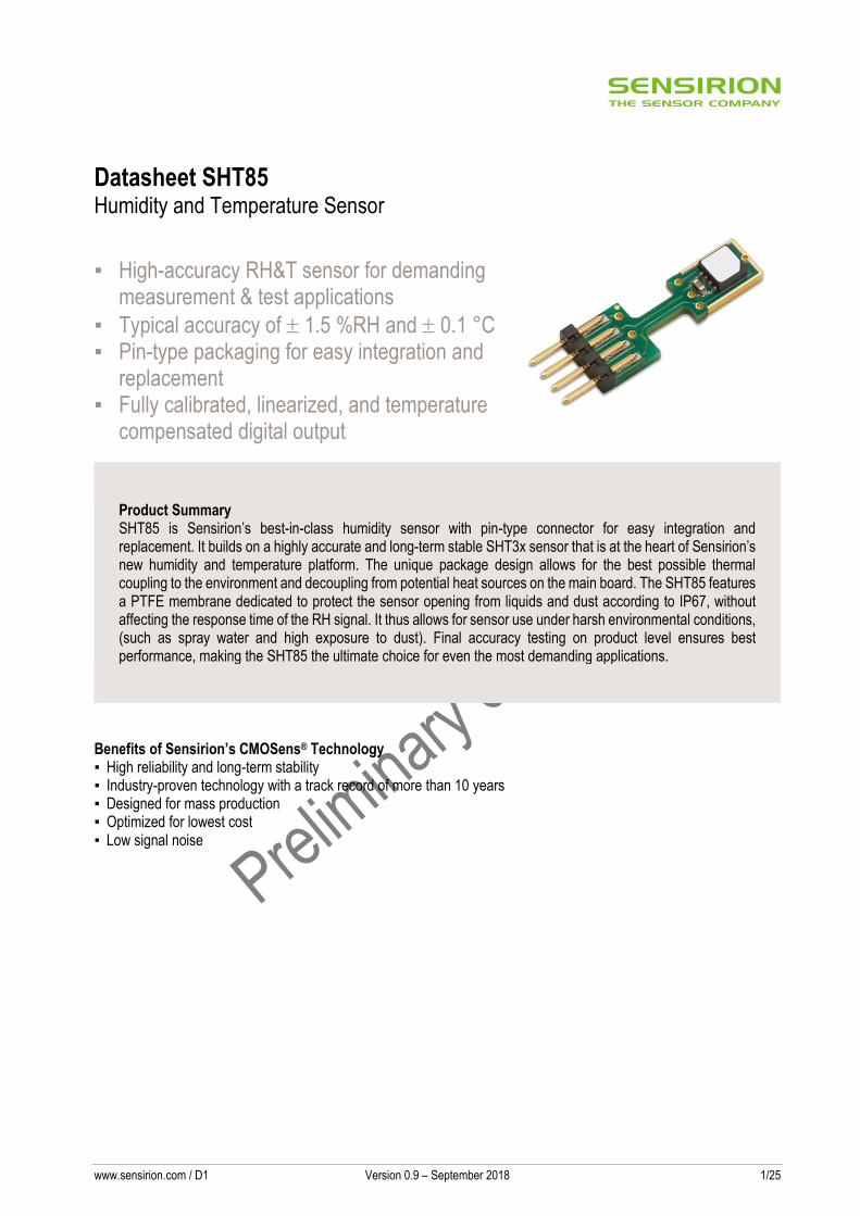
Datasheet SHT85 Humidity and Temperature Sensor
▪ High-accuracy RH&T sensor for demanding measurement & test applications
▪ Typical accuracy of 1.5 %RH and 0.1 °C ▪ Pin-type packaging for easy integration and
replacement ▪ Fully calibrated, linearized, and temperature
compensated digital output
Product Summary SHT85 is Sensirion’s best-in-class humidity sensor with pin-type connector for easy integration and replacement. It builds on a highly accurate and long-term stable SHT3x sensor that is at the heart of Sensirion’s new humidity and temperature platform. The unique package design allows for the best possible thermal coupling to the environment and decoupling from potential heat sources on the main board. The SHT85 features a PTFE membrane dedicated to protect the sensor opening from liquids and dust according to IP67, without affecting the response time of the RH signal. It thus allows for sensor use under harsh environmental conditions, (such as spray water and high exposure to dust). Final accuracy testing on product level ensures best performance, making the SHT85 the ultimate choice for even the most demanding applications.
Benefits of Sensirion’s CMOSens® Technology ▪ High reliability and long-term stability ▪ Industry-proven technology with a track record of more than 10 years ▪ Designed for mass production ▪ Optimized for lowest cost ▪ Low signal noise
www.sensirion.com / D1 Version 0.9 – September 2018 2/25
Content
1 Humidity and Temperature Sensor Specifications 3
2 Electrical Specifications 6
3 Pin Assignment 8
4 Operation and Communication 9
5 Packaging 18
6 Shipping Package 20
7 Quality 21
8 Ordering Information 22
9 Further Information 23
10 Important Notices 24
11 Revision History 25
12 Headquarters and Subsidiaries 25
www.sensirion.com / D1 Version 0.9 – September 2018 3/25
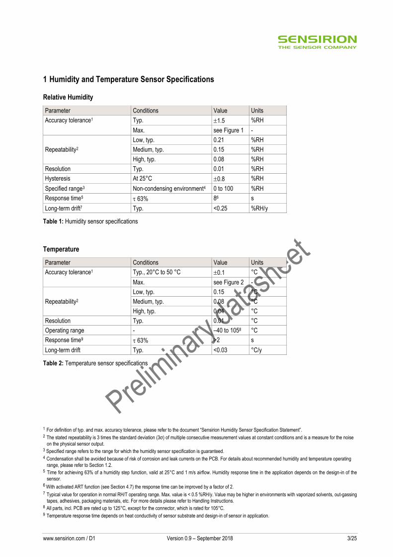
1 Humidity and Temperature Sensor Specifications
Relative Humidity
Parameter Conditions Value Units
Accuracy tolerance1 Typ. 1.5 %RH
Max. see Figure 1 -
Repeatability2
Low, typ. 0.21 %RH
Medium, typ. 0.15 %RH
High, typ. 0.08 %RH
Resolution Typ. 0.01 %RH
Hysteresis At 25°C 0.8 %RH
Specified range3 Non-condensing environment4 0 to 100 %RH
Response time5 63% 86 s
Long-term drift7 Typ. <0.25 %RH/y
Table 1: Humidity sensor specifications
Temperature
Parameter Conditions Value Units
Accuracy tolerance1 Typ., 20°C to 50 °C 0.1 °C
Max. see Figure 2 -
Repeatability2
Low, typ. 0.15 °C
Medium, typ. 0.08 °C
High, typ. 0.04 °C
Resolution Typ. 0.01 °C
Operating range - –40 to 1058 °C
Response time9 63% >2 s
Long-term drift Typ. <0.03 °C/y
Table 2: Temperature sensor specifications
1 For definition of typ. and max. accuracy tolerance, please refer to the document “Sensirion Humidity Sensor Specification Statement”. 2 The stated repeatability is 3 times the standard deviation (3σ) of multiple consecutive measurement values at constant conditions and is a measure for the noise
on the physical sensor output. 3 Specified range refers to the range for which the humidity sensor specification is guaranteed. 4 Condensation shall be avoided because of risk of corrosion and leak currents on the PCB. For details about recommended humidity and temperature operating
range, please refer to Section 1.2. 5 Time for achieving 63% of a humidity step function, valid at 25°C and 1 m/s airflow. Humidity response time in the application depends on the design-in of the
sensor. 6 With activated ART function (see Section 4.7) the response time can be improved by a factor of 2. 7 Typical value for operation in normal RH/T operating range. Max. value is < 0.5 %RH/y. Value may be higher in environments with vaporized solvents, out-gassing
tapes, adhesives, packaging materials, etc. For more details please refer to Handling Instructions. 8 All parts, incl. PCB are rated up to 125°C, except for the connector, which is rated for 105°C. 9 Temperature response time depends on heat conductivity of sensor substrate and design-in of sensor in application.

www.sensirion.com / D1 Version 0.9 – September 2018 4/25
Figure 1: Typical and maximal tolerance for relative humidity in %RH at 25 °C.
Figure 2: Typical and maximal tolerance for temperature sensor in °C
1.1 RH Accuracy at Various Temperatures
Typical RH accuracy at 25°C is defined in Figure 2. For other temperatures, typical accuracy has been evaluated to be as displayed in Figure 4.
±0.0
±0.5
±1.0
±1.5
±2.0
±2.5
±3.0
±3.5
±4.0
0 10 20 30 40 50 60 70 80 90 100
Relative Humidity (%RH)
maximal tolerance
typical tolerance
DRH (%RH)
±0.0
±0.5
±1.0
±1.5
-40 -20 0 20 40 60 80 100 120
Temperature (°C)
maximal tolerance
typical tolerance
DT (°C)DT (°C)DT (°C)DT (°C)DT (°C)DT (°C)DT (°C)DT (°C)DT (°C)DT (°C)DT (°C)DT (°C)DT (°C)DT (°C)DT (°C)DT (°C)DT (°C)DT (°C)

www.sensirion.com / D1 Version 0.9 – September 2018 5/25
RH (%RH) 100 ±2 ±2 ±2 ±2 ±2 ±2 ±2 ±2 ±2
90 ±2 ±2 ±2 ±2 ±2 ±2 ±2 ±2 ±2
80 ±2 ±2 ±2 ±2
70 ±1.5 ±1.5 ±1.5 ±1.5 ±1.5 ±1.5 ±1.5 ±2 ±2
60 ±1.5 ±1.5 ±1.5 ±1.5 ±1.5 ±1.5 ±1.5 ±2 ±2
50 ±1.5 ±1.5 ±1.5 ±1.5 ±1.5 ±1.5 ±1.5 ±2 ±2
40 ±1.5 ±1.5 ±1.5 ±1.5 ±1.5 ±1.5 ±1.5 ±1.5 ±2
30 ±1.5 ±1.5 ±1.5 ±1.5 ±1.5 ±1.5 ±1.5 ±1.5 ±2
20 ±1.5 ±1.5 ±1.5 ±1.5 ±1.5 ±1.5 ±1.5 ±1.5 ±2
10 ±1.5 ±1.5 ±1.5 ±1.5 ±1.5 ±1.5 ±1.5 ±1.5 ±2
0 ±1.5 ±1.5 ±1.5 ±1.5 ±1.5 ±1.5 ±1.5 ±1.5 ±2
0 10 20 30 40 50 60 70 80 Temperature (°C)
Figure 3: Typical accuracy of relative humidity measurements given in %RH for temperatures 0 – 80°C.
1.2 Recommended Operating Conditions
The sensor shows best performance when operated within recommended normal temperature and humidity range of 5 – 60 °C and 20 – 80 %RH, respectively. Long term exposure to conditions outside normal range, especially at high humidity, may temporarily offset the RH signal (e.g. +3%RH after 60h at >80%RH). After returning into the normal temperature and humidity range, the sensor will slowly come back to calibration state by itself. Prolonged exposure to extreme conditions may accelerate ageing.
To ensure stable operation of the humidity sensor, the conditions described in the document “SHTxx Assembly of SMD Packages”, Section “Storage and Handling Instructions” regarding exposure to volatile organic compounds have to be met. Please note as well that this does apply not only to transportation and manufacturing, but also to operation of the SHT85.
www.sensirion.com / D1 Version 0.9 – September 2018 6/25
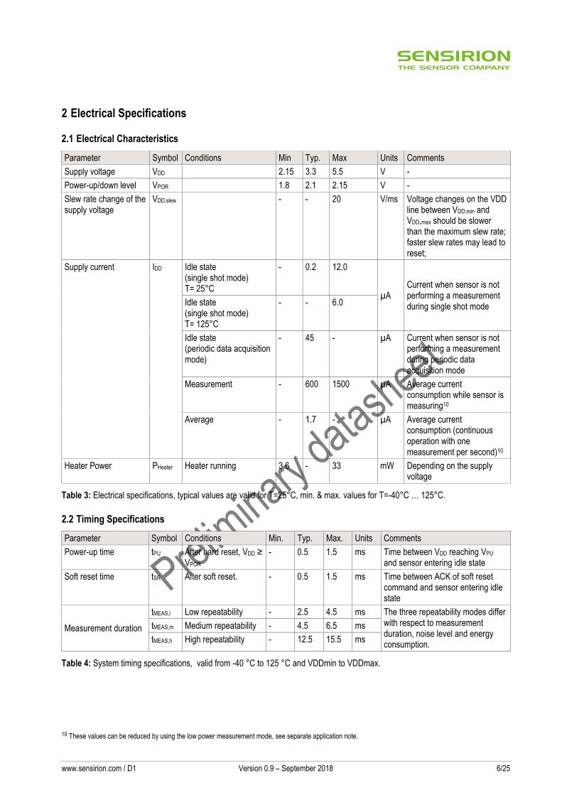
2 Electrical Specifications
2.1 Electrical Characteristics
Parameter Symbol Conditions Min Typ. Max Units Comments
Supply voltage VDD 2.15 3.3 5.5 V -
Power-up/down level VPOR 1.8 2.1 2.15 V -
Slew rate change of the supply voltage
VDD,slew - - 20 V/ms Voltage changes on the VDD line between VDD,min and VDD,max should be slower than the maximum slew rate; faster slew rates may lead to reset;
Supply current IDD Idle state (single shot mode) T= 25°C
- 0.2 12.0
µA Current when sensor is not performing a measurement during single shot mode Idle state
(single shot mode) T= 125°C
- - 6.0
Idle state (periodic data acquisition mode)
- 45 - µA Current when sensor is not performing a measurement during periodic data acquisition mode
Measurement - 600 1500 µA Average current consumption while sensor is measuring10
Average - 1.7 - µA Average current consumption (continuous operation with one measurement per second)10
Heater Power PHeater Heater running 3.6 - 33 mW Depending on the supply voltage
Table 3: Electrical specifications, typical values are valid for T=25°C, min. & max. values for T=-40°C … 125°C.
2.2 Timing Specifications
Parameter Symbol Conditions Min. Typ. Max. Units Comments
Power-up time tPU After hard reset, VDD ≥ VPOR
- 0.5 1.5 ms Time between VDD reaching VPU and sensor entering idle state
Soft reset time tSR After soft reset. - 0.5 1.5 ms Time between ACK of soft reset command and sensor entering idle state
Measurement duration
tMEAS,l Low repeatability - 2.5 4.5 ms The three repeatability modes differ with respect to measurement duration, noise level and energy consumption.
tMEAS,m Medium repeatability - 4.5 6.5 ms
tMEAS,h High repeatability - 12.5 15.5 ms
Table 4: System timing specifications, valid from -40 °C to 125 °C and VDDmin to VDDmax.
10 These values can be reduced by using the low power measurement mode, see separate application note.
www.sensirion.com / D1 Version 0.9 – September 2018 7/25
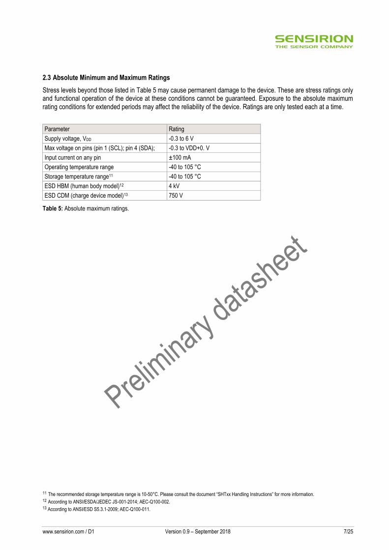
2.3 Absolute Minimum and Maximum Ratings
Stress levels beyond those listed in Table 5 may cause permanent damage to the device. These are stress ratings only and functional operation of the device at these conditions cannot be guaranteed. Exposure to the absolute maximum rating conditions for extended periods may affect the reliability of the device. Ratings are only tested each at a time.
Parameter Rating
Supply voltage, VDD -0.3 to 6 V
Max voltage on pins (pin 1 (SCL); pin 4 (SDA); -0.3 to VDD+0. V
Input current on any pin ±100 mA
Operating temperature range -40 to 105 °C
Storage temperature range11 -40 to 105 °C
ESD HBM (human body model)12 4 kV
ESD CDM (charge device model)13 750 V
Table 5: Absolute maximum ratings.
11 The recommended storage temperature range is 10-50°C. Please consult the document “SHTxx Handling Instructions” for more information. 12 According to ANSI/ESDA/JEDEC JS-001-2014; AEC-Q100-002. 13 According to ANSI/ESD S5.3.1-2009; AEC-Q100-011.
www.sensirion.com / D1 Version 0.9 – September 2018 8/25
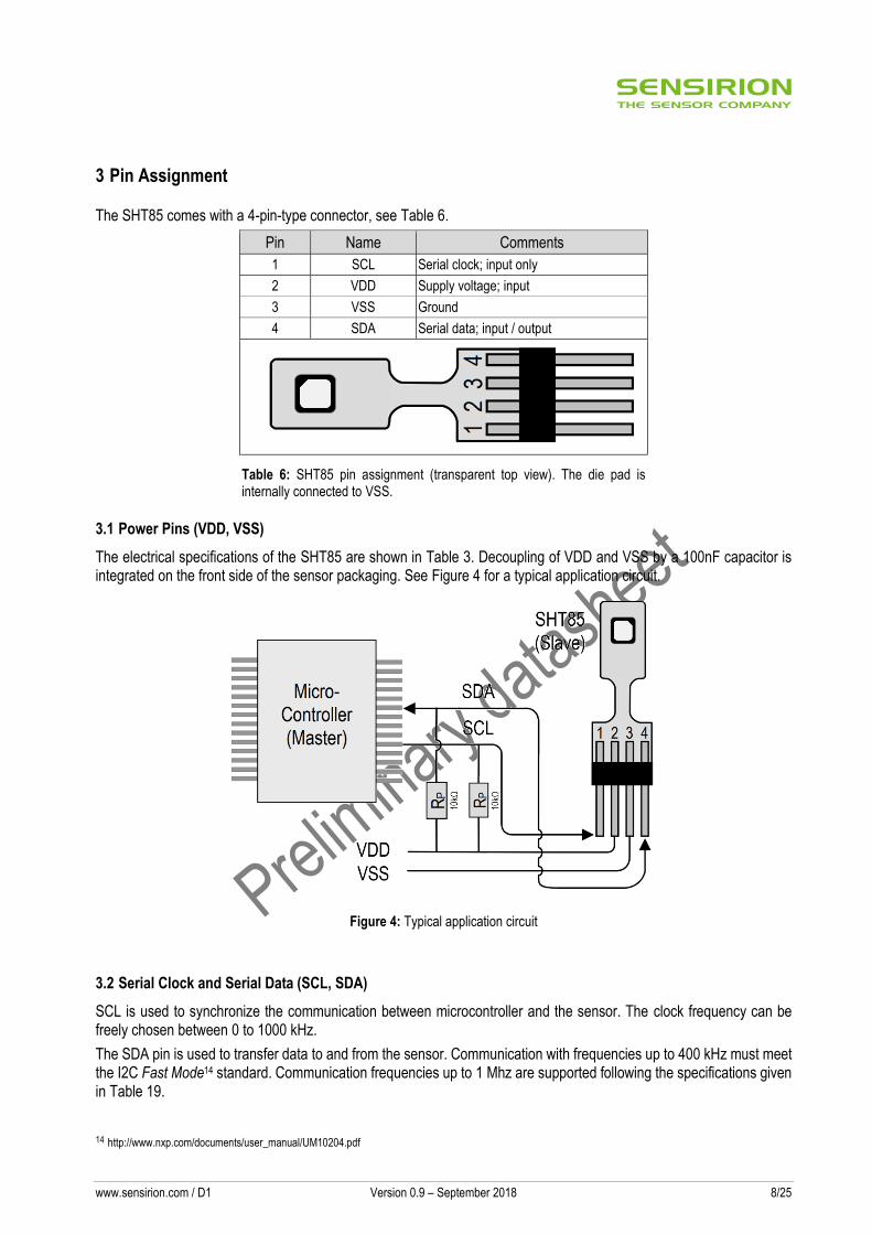
3 Pin Assignment
The SHT85 comes with a 4-pin-type connector, see Table 6.
Pin Name Comments
1 SCL Serial clock; input only
2 VDD Supply voltage; input
3 VSS Ground
4 SDA Serial data; input / output
Table 6: SHT85 pin assignment (transparent top view). The die pad is internally connected to VSS.
3.1 Power Pins (VDD, VSS)
The electrical specifications of the SHT85 are shown in Table 3. Decoupling of VDD and VSS by a 100nF capacitor is integrated on the front side of the sensor packaging. See Figure 4 for a typical application circuit.
Figure 4: Typical application circuit
3.2 Serial Clock and Serial Data (SCL, SDA)
SCL is used to synchronize the communication between microcontroller and the sensor. The clock frequency can be freely chosen between 0 to 1000 kHz.
The SDA pin is used to transfer data to and from the sensor. Communication with frequencies up to 400 kHz must meet the I2C Fast Mode14 standard. Communication frequencies up to 1 Mhz are supported following the specifications given in Table 19.
14 http://www.nxp.com/documents/user_manual/UM10204.pdf
www.sensirion.com / D1 Version 0.9 – September 2018 9/25
4 Operation and Communication
The SHT85 supports I2C fast mode (and frequencies up to 1000 kHz). For detailed information on the I2C protocol, refer to NXP I2C-bus specification15.
After sending a command to the sensor a minimal waiting time of 1ms is needed before another command can be received by the sensor.
Furthermore, to keep self-heating below 0.1°C, SHT85 should not be active for more than 10% of the time.
All SHT85 commands and data are mapped to a 16-bit address space. Additionally, data and commands are protected with a CRC checksum. This increases communication reliability. The 16 bits commands to the sensor already include a 3 bit CRC checksum. Data sent from and received by the sensor is always succeeded by an 8 bit CRC.
In write direction it is mandatory to transmit the checksum, since the SHT85 only accepts data if it is followed by the correct checksum. In read direction it is left to the master to read and process the checksum.
4.1 Power-Up and Communication Start
The sensor starts powering-up after reaching the power-up threshold voltage VPOR specified in Table 3. After reaching this threshold voltage the sensor needs the time tPU to enter idle state. Once the idle state is entered it is ready to receive commands from the master (microcontroller).
Each transmission sequence begins with a START condition (S) and ends with a STOP condition (P) as described in the I2C-bus specification. Whenever the sensor is powered up, but not performing a measurement or communicating, it automatically enters idle state for energy saving. This idle state cannot be controlled by the user.
4.2 Starting a Measurement
A measurement communication sequence consists of a START condition, the I2C write header (7-bit I2C device address plus 0 as the write bit) and a 16-bit measurement command. The proper reception of each byte is indicated by the sensor. It pulls the SDA pin low (ACK bit) after the falling edge of the 8th SCL clock to indicate the reception. A complete measurement cycle is depicted in Table 7.
With the acknowledgement of the measurement command, the SHT85 starts measuring humidity and temperature.
4.3 Measurement Commands for Single Shot Data Acquisition Mode
In this mode one issued measurement command triggers the acquisition of one data pair. Each data pair consists of one 16-bit temperature and one 16-bit humidity value (in this order). During transmission each data value is always followed by a CRC checksum, see Section 4.4.
In single shot mode different measurement commands can be selected. The 16-bit commands are shown in Table 7. They differ with respect to repeatability (low, medium and high).
The repeatability setting influences the measurement duration and thus the overall energy consumption of the sensor. This is explained in Section 2.
15 http://www.nxp.com/documents/user_manual/UM10204.pdf

www.sensirion.com / D1 Version 0.9 – September 2018 10/25
Condition Hex. code
Repeatability MSB LSB
High
0x24
00
Medium 0B
Low 16
e.g. 0x2400: high repeatability measurement.
Table 7: Measurement commands in single shot mode. The first “SCL free” block indicates a minimal waiting time of 1ms. (Clear blocks are controlled by the microcontroller, grey blocks by the sensor).
4.4 Readout of Measurement Results for Single Shot Mode
After the sensor has completed the measurement, the master can read the measurement results (pair of RH & T) by sending a START condition followed by an I2C read header.
The sensor responds to a read header with a not acknowledge (NACK), if the measurement is still ongoing and thus no data is present.
If the measurement is completed, the sensor will acknowledge the reception of the read header and send two bytes of data (temperature) followed by one byte CRC checksum and another two bytes of data (relative humidity) followed by one byte CRC checksum. Each byte must be acknowledged by the microcontroller with an ACK condition for the sensor to continue sending data. If the sensor does not receive an ACK from the master after any byte of data, it will not continue sending data.
The sensor will send the temperature value first and then the relative humidity value. After having received the checksum for the humidity value a NACK and stop condition should be sent (see Table 7).
The I2C master can abort the read transfer with a NACK condition after any data byte if it is not interested in subsequent data, e.g. the CRC byte or the second measurement result, in order to save time.
In case the user needs humidity and temperature data but does not want to process CRC data, it is recommended to read the two temperature bytes of data with the CRC byte (without processing the CRC data); after having read the two humidity bytes, the read transfer can be aborted with a with a NACK.
4.5 Measurement Commands for Periodic Data Acquisition Mode
In this mode one issued measurement command yields a stream of data pairs. Each data pair consists of one 16-bit temperature and one 16-bit humidity value (in this order).
SCL free I2C Address
I2C read headermeasurement completed
measurement ongoing
S R
AC
K
Temperature MSB Temperature LSB
16-bit temperature value Checksum
CRC
AC
K
AC
K
AC
K
Humidity MSB Humidity LSB
16-bit humidity value Checksum
CRC P
AC
K
AC
K
NA
CK
SCL free
I2C read header
I2C Address
measurementongoing:
PRS
NA
CK
I2C Address
16-bit commandI2C write header
S W PAC
K
AC
K
AC
K
Command LSBCommand MSB
no read header for 1ms
www.sensirion.com / D1 Version 0.9 – September 2018 11/25
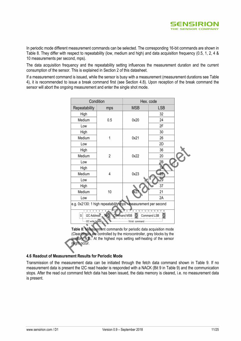
In periodic mode different measurement commands can be selected. The corresponding 16-bit commands are shown in Table 8. They differ with respect to repeatability (low, medium and high) and data acquisition frequency (0.5, 1, 2, 4 & 10 measurements per second, mps).
The data acquisition frequency and the repeatability setting influences the measurement duration and the current consumption of the sensor. This is explained in Section 2 of this datasheet.
If a measurement command is issued, while the sensor is busy with a measurement (measurement durations see Table 4), it is recommended to issue a break command first (see Section 4.8). Upon reception of the break command the sensor will abort the ongoing measurement and enter the single shot mode.
Condition Hex. code
Repeatability mps MSB LSB
High
0.5 0x20
32
Medium 24
Low 2F
High
1 0x21
30
Medium 26
Low 2D
High
2 0x22
36
Medium 20
Low 2B
High
4 0x23
34
Medium 22
Low 29
High
10 0x27
37
Medium 21
Low 2A
e.g. 0x2130: 1 high repeatability mps - measurement per second
Table 8: Measurement commands for periodic data acquisition mode (Clear blocks are controlled by the microcontroller, grey blocks by the sensor). N.B.: At the highest mps setting self-heating of the sensor might occur.
4.6 Readout of Measurement Results for Periodic Mode
Transmission of the measurement data can be initiated through the fetch data command shown in Table 9. If no measurement data is present the I2C read header is responded with a NACK (Bit 9 in Table 9) and the communication stops. After the read out command fetch data has been issued, the data memory is cleared, i.e. no measurement data is present.
S
AC
K
WI2C Address
1 2 3 4 5 6 7 8 9
AC
K
Command MSB
1 2 3 4 5 6 7 8 9
AC
K
Command LSB
10 11 12 13 14 15 16 17 18
16-bit commandI2C write header

www.sensirion.com / D1 Version 0.9 – September 2018 12/25
Command Hex code Fetch Data 0x E0 00
Table 9: Fetch Data command (Clear blocks are controlled by the microcontroller, grey blocks by the sensor).
4.7 ART Command
The ART (accelerated response time) feature can be activated by issuing the command in Table 10. After issuing the ART command the sensor will start acquiring data with a frequency of 4Hz.
The ART command is structurally similar to any other command in Table 8. Hence Section 4.5 applies for starting a measurement, Section 4.6 for reading out data and Section 4.8 for stopping the periodic data acquisition.
Command Hex Code Periodic Measurement with
ART 0x2B32
Table 10: Command for a periodic data acquisition with the ART feature (Clear blocks are controlled by the microcontroller, grey blocks by the sensor).
4.8 Break command / Stop Periodic Data Acquisition Mode
The periodic data acquisition mode can be stopped using the break command shown in Table 11. It is recommended to stop the periodic data acquisition prior to sending another command (except Fetch Data command) using the break command. Upon reception of the break command the sensor will abort the ongoing measurement and enter the single shot mode. This takes 1ms.
Command Hex Code Break 0x3093
Table 11: Break command (Clear blocks are controlled by the microcontroller, grey blocks by the sensor).
S
AC
K
WI2C Address
1 2 3 4 5 6 7 8 9
AC
K
Command MSB
1 2 3 4 5 6 7 8 9
AC
K
Command LSB
10 11 12 13 14 15 16 17 18
16-bit commandI2C write header
www.sensirion.com / D1 Version 0.9 – September 2018 13/25
4.9 Reset
A system reset of the SHT85 can be generated externally by issuing a command (soft reset). Additionally, a system reset is generated internally during power-up. During the reset procedure the sensor will not process commands.
Interface Reset
If communication with the device is lost, the following signal sequence will reset the serial interface: While leaving SDA high, toggle SCL nine or more times. This must be followed by a Transmission Start sequence preceding the next command. This sequence resets the interface only. The status register preserves its content.
Soft Reset / Re-Initialization
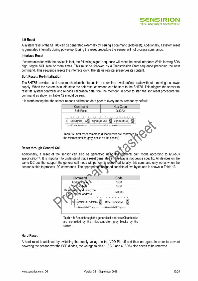
The SHT85 provides a soft reset mechanism that forces the system into a well-defined state without removing the power supply. When the system is in idle state the soft reset command can be sent to the SHT85. This triggers the sensor to reset its system controller and reloads calibration data from the memory. In order to start the soft reset procedure the command as shown in Table 12 should be sent.
It is worth noting that the sensor reloads calibration data prior to every measurement by default.
Command Hex Code Soft Reset 0x30A2
Table 12: Soft reset command (Clear blocks are controlled by the microcontroller, grey blocks by the sensor).
Reset through General Call
Additionally, a reset of the sensor can also be generated using the “general call” mode according to I2C-bus specification15. It is important to understand that a reset generated in this way is not device specific. All devices on the same I2C bus that support the general call mode will perform a reset. Additionally, this command only works when the sensor is able to process I2C commands. The appropriate command consists of two bytes and is shown in Table 13.
Command Code Address byte 0x00
Second byte 0x06
Reset command using the general call address
0x0006
Table 13: Reset through the general call address (Clear blocks are controlled by the microcontroller, grey blocks by the sensor).
Hard Reset
A hard reset is achieved by switching the supply voltage to the VDD Pin off and then on again. In order to prevent powering the sensor over the ESD diodes, the voltage to pins 1 (SCL) and 4 (SDA) also needs to be removed.
S
AC
K
General Call Address
1 2 3 4 5 6 7 8 9
AC
K
Reset Command
1 2 3 4 5 6 7 8 9
General Call 1st byte General Call 2nd byte
www.sensirion.com / D1 Version 0.9 – September 2018 14/25
4.10 Heater
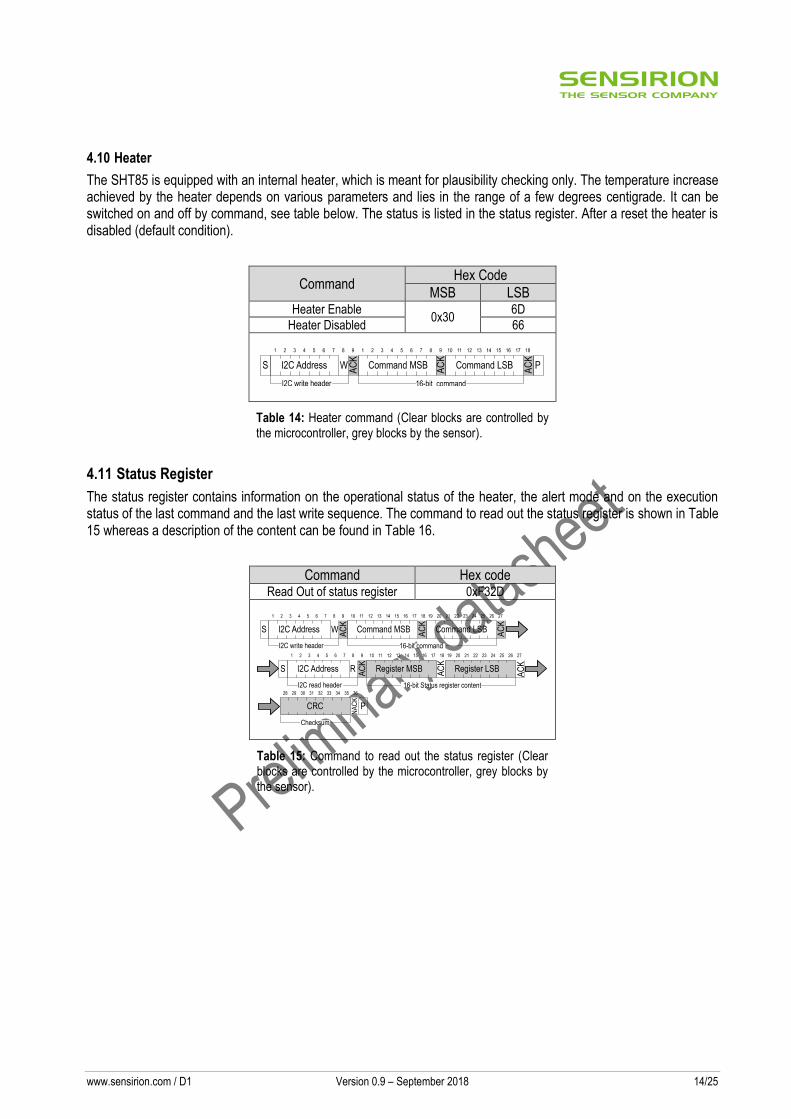
The SHT85 is equipped with an internal heater, which is meant for plausibility checking only. The temperature increase achieved by the heater depends on various parameters and lies in the range of a few degrees centigrade. It can be switched on and off by command, see table below. The status is listed in the status register. After a reset the heater is disabled (default condition).
Command Hex Code
MSB LSB Heater Enable
0x30 6D
Heater Disabled 66
Table 14: Heater command (Clear blocks are controlled by the microcontroller, grey blocks by the sensor).
4.11 Status Register
The status register contains information on the operational status of the heater, the alert mode and on the execution status of the last command and the last write sequence. The command to read out the status register is shown in Table 15 whereas a description of the content can be found in Table 16.
Command Hex code Read Out of status register 0xF32D
Table 15: Command to read out the status register (Clear blocks are controlled by the microcontroller, grey blocks by the sensor).
www.sensirion.com / D1 Version 0.9 – September 2018 15/25
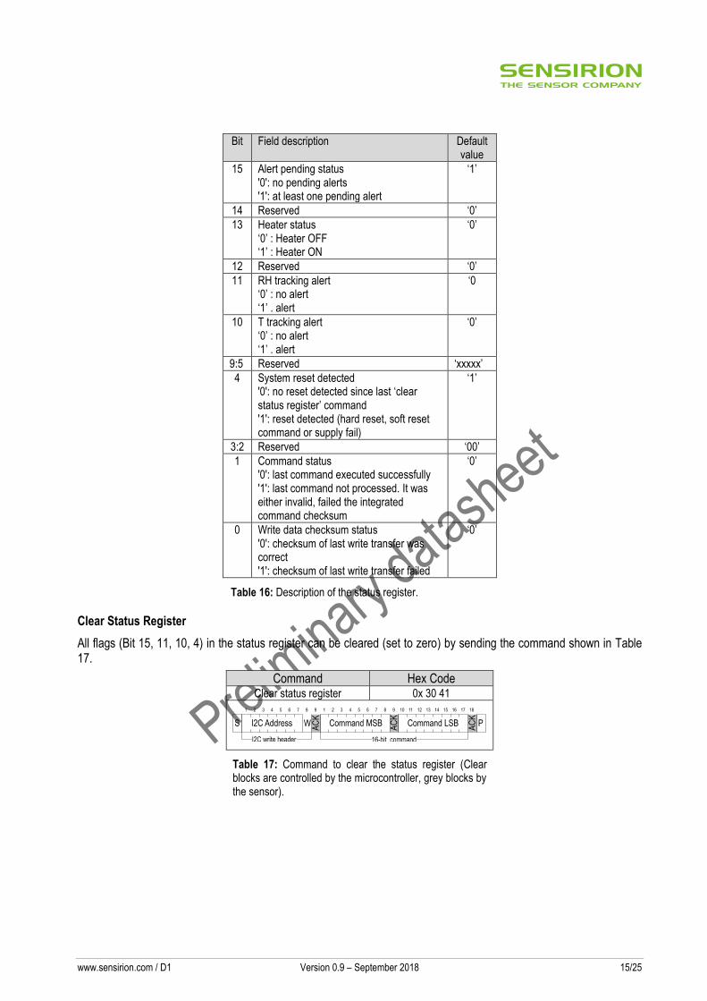
Bit Field description Default value
15 Alert pending status '0': no pending alerts '1': at least one pending alert
‘1’
14 Reserved ‘0’
13 Heater status ‘0’ : Heater OFF ‘1’ : Heater ON
‘0’
12 Reserved ‘0’
11 RH tracking alert ‘0’ : no alert ‘1’ . alert
‘0
10 T tracking alert ‘0’ : no alert ‘1’ . alert
‘0’
9:5 Reserved ‘xxxxx’
4 System reset detected '0': no reset detected since last ‘clear status register’ command '1': reset detected (hard reset, soft reset command or supply fail)
‘1’
3:2 Reserved ‘00’
1 Command status '0': last command executed successfully '1': last command not processed. It was either invalid, failed the integrated command checksum
‘0’
0 Write data checksum status '0': checksum of last write transfer was correct '1': checksum of last write transfer failed
‘0’
Table 16: Description of the status register.
Clear Status Register
All flags (Bit 15, 11, 10, 4) in the status register can be cleared (set to zero) by sending the command shown in Table 17.
Command Hex Code Clear status register 0x 30 41
Table 17: Command to clear the status register (Clear blocks are controlled by the microcontroller, grey blocks by the sensor).
www.sensirion.com / D1 Version 0.9 – September 2018 16/25
4.12 Checksum Calculation
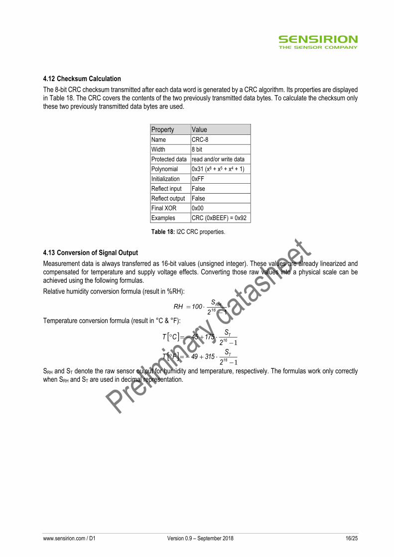
The 8-bit CRC checksum transmitted after each data word is generated by a CRC algorithm. Its properties are displayed in Table 18. The CRC covers the contents of the two previously transmitted data bytes. To calculate the checksum only these two previously transmitted data bytes are used.
Property Value
Name CRC-8
Width 8 bit
Protected data read and/or write data
Polynomial 0x31 (x8 + x5 + x4 + 1)
Initialization 0xFF
Reflect input False
Reflect output False
Final XOR 0x00
Examples CRC (0xBEEF) = 0x92
Table 18: I2C CRC properties.
4.13 Conversion of Signal Output
Measurement data is always transferred as 16-bit values (unsigned integer). These values are already linearized and compensated for temperature and supply voltage effects. Converting those raw values into a physical scale can be achieved using the following formulas.
Relative humidity conversion formula (result in %RH):
1
16
RH
2
S 100 RH
Temperature conversion formula (result in °C & °F):
1
1
16
T
16
T
2
S 315 49 F T
2
S 175 45 C T
SRH and ST denote the raw sensor output for humidity and temperature, respectively. The formulas work only correctly when SRH and ST are used in decimal representation.

www.sensirion.com / D1 Version 0.9 – September 2018 17/25
4.14 Communication Timing
Parameter Symbol Conditions Min. Typ. Max. Units Comments
SCL clock frequency fSCL 0 - 1000 kHz
Hold time (repeated) START condition
tHD;STA After this period, the first clock pulse is generated
0.24 - - µs
LOW period of the SCL clock
tLOW 0.53 - - µs
HIGH period of the SCL clock
tHIGH 0.26 - - µs
SDA hold time tHD;DAT 0 - 250 ns Transmitting data
0 - - - ns Receiving data
SDA set-up time tSU;DAT 100 - - ns
SCL/SDA rise time tR - - 300 ns
SCL/SDA fall time tF - - 300 ns
SDA valid time tVD;DAT - - 0.9 µs
Set-up time for a repeated START condition
tSU;STA 0.26 - - µs
Set-up time for STOP condition
tSU;STO 0.26 - - µs
Capacitive load on bus line CB - - 400 pF
Low level input voltage VIL 0 - 0.3xVDD V
High level input voltage VIH 0.7xVDD - 1xVDD V
Low level output voltage VOL 33 mA sink current - - 0.4 V
Table 19: Timing specifications for I2C communication, valid for T=-40°C … 125°C and VDD = VDDmin… VDDmax. The nomenclature above is according to the I2C Specification (UM10204, Rev. 6, April 4, 2014).
Figure 5: Timing diagram for digital input/output pads. SDA directions are seen from the sensor. Bold SDA lines are controlled by the sensor, plain SDA lines are controlled by the micro-controller. Note that SDA valid read time is triggered by falling edge of preceding toggle.
SCL 70%
30%
tLOW
1/fSCL
tHIGH tR tF
SDA 70%
30%
tSU;DAT tHD;DAT
DATA IN
tR
SDA 70%
30%
DATA OUT
tVD;DAT tF

www.sensirion.com / D1 Version 0.9 – September 2018 18/25
5 Packaging
The SHT85 is supplied in a single-in-line pin type package. The SHT35-DIS sensor housing consists of an epoxy-based mold compound, see “Datasheet SHT3x-DIS” for more information. The sensor opening of the housing is protected by a PTFE membrane dedicated to protect the sensor opening from liquids and dust according to IP67, see “Datasheet Membrane Option” for more information. The sensor head is connected to the pins by a small bridge to minimize heat conduction and response times. The pins are soldered to the FR4 substrate by lead-free solder paste. The gold plated backside of the sensor head is connected to the VSS pin. A 100nF capacitor is mounted on the front side between VDD and VSS. The device is fully RoHS compliant – thus it is free of of Pb, Cd, Hg, Cr(6+), PBB and PBDE. All pins are Au plated to avoid corrosion. They can be soldered or mate with most 1.27 mm (0.05’’) sockets, for example: Preci-dip / Mill-Max R851-83-004-20-001 or similar. When the sensor is further processed by soldering, it should be ensured that the solder connections between pins and the SHT85 PCB are not melted.
5.1 Traceability
The SHT85 provides a device specific serial number, which can be read-out via the serial interface (I2C), see the command in Table 20. The Serial number allows an unambiguous identification of each individual device.
Command Hex Code Get Serial Number 0x 36 82
Table 20: Command to read out the Serial Number (Clear blocks are controlled by the microcontroller, grey blocks by the sensor.)
After issuing the measurement command and sending the ACK Bit the sensor needs the time tIDLE = 0.5ms to respond to the I2C read header with an ACK Bit. Hence it is recommended to wait tIDLE =0.5ms before issuing the read header. The Get Serial Number command returns 2 words; every word is followed by a CRC Checksum. Together the 2 words (SNB_3 to SNB_0 in Table 20, SNB_0 is the LSB, whereas SNB_3 is the MSB) constitute a unique serial number with a length of 32 bit. This serial number can be used to identify each sensor individually.
AC
K
AC
K
AC
KA
CK
tIDLE
9 36
SNB_3 SNB_2 CRC
AC
K
AC
K
AC
K
Serial Number Word 1 Checksum
37 63
SNB_1 SNB_0 CRC
AC
K
AC
K
AC
K
Serial Number Word 2 Checksum
P
SNB_3
I2C Address Command MSB Command LSB
16-bit command16-bit commandI2C write header
I2C read header
I2C Address
S W
S R
1 2 3 4 5 6 7 8 9 10 11 12 13 14 15 16 17 18 19 20 21 22 23 24 25 26 27
1 2 3 4 5 6 7 8
AC
KA
CK
9
www.sensirion.com / D1 Version 0.9 – September 2018 19/25
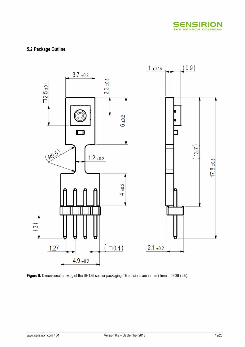
5.2 Package Outline
Figure 6: Dimensional drawing of the SHT85 sensor packaging. Dimensions are in mm (1mm = 0.039 inch).

www.sensirion.com / D1 Version 0.9 – September 2018 20/25
6 Shipping Package
SHT85 are shipped in 32mm tape at 50pcs each. Dimensions of packaging tape are given in Figure 7. All tapes have a 10 pockets empty leader tape (first pockets of the tape) and a 10 pockets empty trailer tape (last pockets of the tape).
Figure 7 Tape configuration and unit orientation within tape, dimensions in mm (1mm = 0.039inch).
www.sensirion.com / D1 Version 0.9 – September 2018 21/25
7 Quality
Qualification of the SHT85 is performed based on JEDEC guidelines. Furthermore, the SHT3x-DIS component qualification is based on the AEC Q 100 qualification test method.
7.1 Material Contents
The device is fully RoHS compliant, e.g. free of Pb, Cd, and Hg.
www.sensirion.com / D1 Version 0.9 – September 2018 22/25
8 Ordering Information
The SHT85 can be ordered in tape and reel packaging, see Table 21. The reels are sealed into antistatic ESD bags.
Sensor Type Packaging Quantity Order Number
SHT85 Tape Stripes 50 3.000.074
Table 21 SHT85 ordering information.

www.sensirion.com / D1 Version 0.9 – September 2018 23/25
9 Further Information
For more in-depth information on the SHT85 and its application please consult the documents in Table 22. Parameter values specified in the datasheet overrule possibly conflicting statements given in references cited in this datasheet.
Document Name Description Source
SHT85 Shipping Package Describes the standard shipping package Available upon request.
Handling of SMD Packages Humidity Sensors
Assembly Guide Available for download at the Sensirion humidity sensors download center: www.sensirion.com/humidity-download
Datasheet Humidity Sensor SHT3x Digital
All specifications of the SHT35-DIS Available for download at the Sensirion humidity sensors download center: www.sensirion.com/humidity-download
Datasheet Humidity Sensor Filter Membrane SHT3x
All relevant specifications of the filter membrane
Available for download at the Sensirion humidity sensors download center: www.sensirion.com/humidity-download
Handling Instructions Humidity Sensors
Guidelines for proper handling of SHTxx humidity sensors
Available for download at the Sensirion humidity sensors download center: www.sensirion.com/humidity-download
Specification Statement Humidity Sensors
Definition of sensor specifications. Available for download at the Sensirion humidity sensors download center: www.sensirion.com/humidity-download
Table 22 Documents containing further information relevant for the SHT85.
www.sensirion.com / D1 Version 0.9 – September 2018 24/25
10 Important Notices
10.1 Warning, Personal Injury
Do not use this product as safety or emergency stop devices or in any other application where failure of the product could result in personal injury. Do not use this product for applications other than its intended and authorized use. Before installing, handling, using or servicing this product, please consult the data sheet and application notes. Failure to comply with these instructions could result in death or serious injury. If the Buyer shall purchase or use SENSIRION products for any unintended or unauthorized application, Buyer shall defend, indemnify and hold harmless SENSIRION and its officers, employees, subsidiaries, affiliates and distributors against all claims, costs, damages and expenses, and reasonable attorney fees arising out of, directly or indirectly, any claim of personal injury or death associated with such unintended or unauthorized use, even if SENSIRION shall be allegedly negligent with respect to the design or the manufacture of the product.
10.2 ESD Precautions
The inherent design of this component causes it to be sensitive to electrostatic discharge (ESD). To prevent ESD-induced damage and/or degradation, take customary and statutory ESD precautions when handling this product. See application note “ESD, Latchup and EMC” for more information.
10.3 Warranty
SENSIRION warrants solely to the original purchaser of this product for a period of 12 months (one year) from the date of delivery that this product shall be of the quality, material and workmanship defined in SENSIRION’s published specifications of the product. Within such period, if proven to be defective, SENSIRION shall repair and/or replace this product, in SENSIRION’s discretion, free of charge to the Buyer, provided that: ▪ notice in writing describing the defects shall be given to SENSIRION within fourteen (14) days after their appearance; ▪ such defects shall be found, to SENSIRION’s reasonable satisfaction, to have arisen from SENSIRION’s faulty design, material, or workmanship; ▪ the defective product shall be returned to SENSIRION’s factory at the Buyer’s expense; and ▪ the warranty period for any repaired or replaced product shall be limited to the unexpired portion of the original period. This warranty does not apply to any equipment which has not been installed and used within the specifications recommended by SENSIRION for the intended and proper use of the equipment. EXCEPT FOR THE WARRANTIES EXPRESSLY SET FORTH HEREIN, SENSIRION MAKES NO WARRANTIES, EITHER EXPRESS OR IMPLIED, WITH RESPECT TO THE PRODUCT. ANY AND ALL WARRANTIES, INCLUDING WITHOUT LIMITATION, WARRANTIES OF MERCHANTABILITY OR FITNESS FOR A PARTICULAR PURPOSE, ARE EXPRESSLY EXCLUDED AND DECLINED. SENSIRION is only liable for defects of this product arising under the conditions of operation provided for in the data sheet and proper use of the goods. SENSIRION explicitly disclaims all warranties, express or implied, for any period during which the goods are operated or stored not in accordance with the technical specifications. SENSIRION does not assume any liability arising out of any application or use of any product or circuit and specifically disclaims any and all liability, including without limitation consequential or incidental damages. All operating parameters, including without limitation recommended parameters, must be validated for each customer’s applications by customer’s technical experts. Recommended parameters can and do vary in different applications. SENSIRION reserves the right, without further notice, (i) to change the product specifications and/or the information in this document and (ii) to improve reliability, functions and design of this product. Copyright© 2018, by SENSIRION. CMOSens® is a trademark of Sensirion All rights reserved
www.sensirion.com / D1 Version 0.9 – September 2018 25/25
11 Revision History
Release Date Version Page(s) Changes
28 September 2018 0.9 All Initial Preliminary Release
12 Headquarters and Subsidiaries
SENSIRION AG Laubisruetistr. 50 CH-8712 Staefa ZH Switzerland phone: +41 44 306 40 00 fax: +41 44 306 40 30 [email protected] www.sensirion.com
Sensirion Inc. USA phone: +1 312 690 5858 [email protected] www.sensirion.com Sensirion Japan Co. Ltd. phone: +81 3 3444 4940 [email protected] www.sensirion.co.jp
Sensirion Korea Co. Ltd. phone: +82 31 337 7700~3 [email protected] www.sensirion.co.kr Sensirion China Co. Ltd. phone: +86 755 8252 1501 [email protected] www.sensirion.com.cn/
Sensirion Taiwan Co. Ltd. phone: +41 44 306 40 00 [email protected]
To find your local representative, please visit www.sensirion.com/contact


![Maximal Forklift [Master Brochure]](https://img.pdfslide.net/doc/110x75/5571f82349795991698cb8bf/maximal-forklift-master-brochure.jpg)

