Embed Size (px)
Citation preview

Manual No.: 13927003
Date of Release 18.05.2009
Movipol-3Instruction Manual

Movipol-3 Instruction Manual
Table of Contents Page User’s Guide .............................................................. 1 Reference Guide ...................................................... 16 Quick Reference Guide ............................................ 21
Always state Serial No and Voltage/frequency if you have technical questions or when ordering spare parts. You will find the Serial No. and Voltage on the type plate of the machine itself. We may also need the Date and Article No of the manual. This information is found on the front cover. The following restrictions should be observed, as violation of the restrictions may cause cancellation of Struers legal obligations: Instruction Manuals: Struers Instruction Manual may only be used in connection with Struers equipment covered by the Instruction Manual. Service Manuals: Struers Service Manual may only be used by a trained technician authorised by Struers. The Service Manual may only be used in connection with Struers equipment covered by the Service Manual. Struers assumes no responsibility for errors in the manual text/illustrations. The information in this manual is subject to changes without notice. The manual may mention accessories or parts not included in the present version of the equipment. The contents of this manual is the property of Struers. Reproduction of any part of this manual without the written permission of Struers is not allowed. All rights reserved. © Struers 2009. Struers A/S Pederstrupvej 84 DK-2750 Ballerup Denmark Telephone +45 44 600 800 Fax +45 44 600 801

Movipol-3 Instruction Manual
Movipol-3 Safety Precaution Sheet To be read carefully before use 1. The operator must be fully instructed in the use of the apparatus,
according to the User's Guide.
2. The operator must be fully instructed in the use of the electrolytes used with Movipol-3.
3. Observe the current safety precautions regarding the handling, mixing, filling and disposal of the electrolyte (see section Safety Precautions). The Material Safety Data Sheet for each of the Struers electrolytes can be supplied upon request.
4. Be sure that the actual voltage corresponds to the voltage stated on the type plate of the apparatus.
5. Check that the apparatus is standing firmly on the support. If the apparatus is carried or hung by the shoulder strap, check that the strap is intact and that the buckle is correctly fastened.
6. Always check that the pump motor is working before taking the pencil out of its holder.
7. Always place the pencil in its holder when it is not used.
8. Do not leave the apparatus unattended when filled with electrolyte.
9. Make sure that the apparatus is safely secured during transportation and that is does not contain electrolyte.
10. The maximum polishing voltage allowed at the work site must be observed.
The equipment should only be used for its intended purpose and as detailed in the Instruction Manual. The equipment is designed for use with consumables supplied by Struers. If subjected to misuse, improper installation, alteration, neglect, accident or improper repair, Struers will accept no responsibility for damage(s) to the user or the equipment. Dismantling of any part of the equipment, during service or repair, should always be performed by a qualified technician (electromechanical, electronic, mechanical, pneumatic, etc.).

Movipol-3 Instruction Manual
Disposal Equipment marked with a WEEE symbol contain electrical and electronic components and must not be disposed of as general waste. Please contact your local authorities for information on the correct method of disposal in accordance with national legislation.

Movipol-3 Instruction Manual
1
User’s Guide Table of Contents Page
1. Getting Started Checking the Contents of Packing .................................................... 3 Placing Movipol-3 .............................................................................. 3 Getting Acquainted with Movipol-3 .................................................... 4 Supplying Power ............................................................................... 5
Connecting the Transformer .................................................... 5 Charging the Batteries ...................................................................... 5 Connecting the Pump Motor and Cathode ........................................ 5 Connecting the Anode ....................................................................... 5 External Etching Operations .............................................................. 5
2. Operation Using the Controls............................................................................. 6
Front Panel Controls ................................................................ 6 Safety Functions ............................................................................... 7
Cut-out of Pump Motor ............................................................. 7 Current Limiter Function of the Polish/Etch Circuit ................... 7 Cut-out of Polish/Etch Circuit ................................................... 7 Cut-out in case of under-voltage .............................................. 7
Mounting the Container ..................................................................... 7 Dismounting the Container ................................................................ 7 Mounting the Pump-Container Unit ................................................... 8 Dismounting the Pump-Container Unit .............................................. 8 Filling Electrolyte into the Container .................................................. 8 Emptying the Container of Electrolyte ............................................... 8 Mounting the Polishing Chamber ...................................................... 8 Starting the Polishing/Etching Process .............................................. 9 Stopping the Polishing/Etching Process ............................................ 9 Cleaning the Container and the Pump ............................................ 11 Voltage Examples ........................................................................... 11
Cast Iron. 3.4% C, 0.29% Si, 0.6% Mn, 0.3% P ..................... 11 Duplex Steel ........................................................................... 11 Commercial Pure Aluminium 99.5% Al ................................... 11 Stainless Steel ....................................................................... 12 Low Carbon Steel 0.1% C ...................................................... 12 High Carbon Steel .................................................................. 12 Titanium Alloys ....................................................................... 12

Movipol-3 Instruction Manual
2
3. Safety precautions Electricity ......................................................................................... 13 Electrolytes in General .................................................................... 13 Perchloric Acid in Particular ............................................................ 13 Training of Operators ...................................................................... 14 Mixing the Solution .......................................................................... 14 Storage of Perchloric Acid or Solution ............................................. 14 Fire and Explosion Hazards ............................................................ 14 Disposal .......................................................................................... 15 Working with Movipol-3 in the field .................................................. 15
Dangerous Localities .............................................................. 15 Safety Measures .................................................................... 15 Dangerous situations ............................................................. 15

Movipol-3 Instruction Manual
3
1. Getting Started In the packing box you should find the following parts: 1 Movipol-3 with control unit, pump, pencil 1 Transformer 1 Container for electrolyte 1 Anode wire 1 Anode clamp 1 Magnet 1 Shoulder strap 10 Polishing Chambers 1 Funnel 1 Set of Instruction Manuals Movipol-3 is a portable apparatus for field electropolishing. If possible the apparatus should be placed on a stable support. If not it can be hung by the shoulder trap in a suitable place. During transportation the apparatus must not contain electrolyte and should be secured in order not to turn upside down.
Checking the Contents of Packing
Placing Movipol-3
Movipol-3 Instruction Manual
4
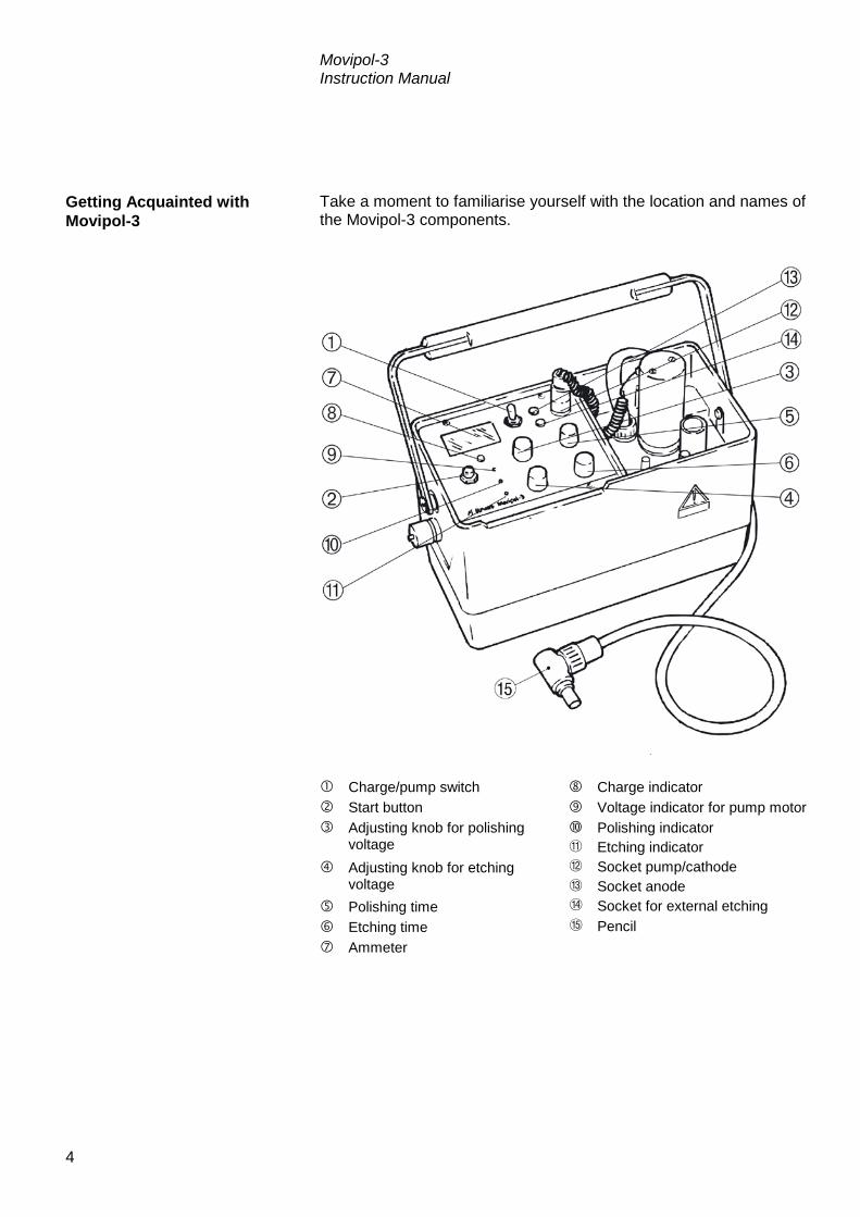
Take a moment to familiarise yourself with the location and names of the Movipol-3 components.
Charge/pump switch Charge indicator Start button Voltage indicator for pump motor Adjusting knob for polishing
voltage Polishing indicator Etching indicator
Adjusting knob for etching voltage
Socket pump/cathode Socket anode
Polishing time Socket for external etching Etching time Pencil Ammeter
Getting Acquainted with Movipol-3

Movipol-3 Instruction Manual
5
Connect the mains cable to the mains. Connect the 42V multi plug to the left side of Movipol-3. Switch O/Charge - l/Pump to top position, the batteries of
Movipol-3 are now being charged. When the batteries are fully charged, the Charge Indicator lights green. If the batteries need charging the Charge Indicator will light red.
Even though the batteries are factory charged, Struers recommends the charging of Movipol-3 batteries 1-2 hours before operating the apparatus.
Connect the multi plug to the socket in the control unit with the
screw cap. Both the electrolyte pump motor and the cathode in the pencil are now connected to the control unit.
Place the banana plug of the anode wire in the socket, Anode.
The connection to the sample is established with the enclosed magnet or clamp.
When external etching operations should be carried out, i.e.
when using a cathode connection other than the built-in cathode in the pencil, the black socket, Output Volt 2-90V DC should be used as cathode connection.
Supplying Power IMPORTANT Check that the mains voltage corresponds to the voltage stated on the type
plate on the side of the machine.
Connecting the Transformer
Charging the Batteries
WARNING A fully charged set of batteries will self-discharge in 6 months, and a
complete discharging may reduce the lifetime. Therefore the batteries should be charged at regular intervals.
IMPORTANT When the transformer is being used Movipol-3 should only be operated
when the Charge Indicator lights green or yellow.
Connecting the Pump Motor and Cathode
Connecting the Anode
External Etching Operations

Movipol-3 Instruction Manual
6
2. Operation
Name Function Name Function
O/CHARGE I/PUMP SWITCH
When switched to O/Charge the batteries are being charged if the apparatus is connected to mains. When switched to l/Pump the pump motor starts operating.
AMMETER
For reading the amperage during the polishing/etching process. The range of 0-2 is used for polishing. The range of 0-0.2 A is used for etching. Changing between the ranges is done automatically when the timers switch from polishing to etching.
START BUTTON
Push button for starting the polishing/etching process.
CHARGE INDICATOR
Indicates the battery charging level. When connected to 42V AC possible readings are as follows: Battery Charging Level O/ I/ Charge Pump Medium charged Yellow Green Fully charged Green Green Not Charged Red Red
ADJUSTING KNOB FOR POLISHING VOLTAGE
Adjusting knob for setting the voltage for polishing. It can be set in the range of 10-90 V. The voltage range of 60-90 volt DC is marked with a voltage danger warning.
VOLTAGE INDICATOR FOR PUMP MOTOR
Indicates whether the pump is supplied with sufficient voltage: 0: The apparatus is switched off. Yellow: Pump motor in operation at sufficient voltage.
Red: Pump motor blocked due to overload of pump motor or too low voltage. Electrical circuit switched off due to overload.
ADJUSTING KNOB FOR ETCHING VOLTAGE
Adjusting knob for setting the voltage for etching.
POLISHING INDICATOR
The Polishing Indicator lights red when the polishing process is running and is switched off when the process is finished.
POLISHING TIME
Adjusting knob for setting the time of polishing. When set to ∞ the process continues until the knob is set to zero.
ETCHING INDICATOR
The Etching Indicator lights red when the etching process is running and is switched off when the process is finished.
ETCHING TIME
Adjusting knob for setting the time of etching. When set to ∞ the process continues until the knob is set to zero.
SOCKET PUMP/ CATHODE
For connecting the pump motor and cathode to the control unit.
Using the Controls Front Panel Controls

Movipol-3 Instruction Manual
7
Name Function Name Function
SOCKET ANODE
For connecting the anode wire to the control unit.
SOCKET FOR EXTERNAL ETCHING
For connecting the cathode when external etching operations should be carried out.
In case of higher load than 1 A the cut-out function is activated. The Voltage Indicator for Pump Motor will light red. The apparatus can be restarted when the error has been eliminated. In case of a voltage range of 70-90 V the current is limited corresponding to the maximum effect of the transistors (140 VA). In case of a voltage range of 2-70 V at 2 A the cut-out function is activated and an alarming signal is heard. When the error has been corrected the apparatus can be restarted. In case of overload the circuit is cut out and the Voltage indicator for Pump Motor lights red. The apparatus can be restarted after cooling when the indicator lights yellow. Under-voltage may occur using insufficiently charged batteries. The cut out function for under-voltage will disconnect the process and an alarm signal is heard. Place the pump in the container. Press down the black knobs and turn them until the markings
turn towards the pump. Check that the container is firmly locked. Press the two black knobs down and turn them so that the
markings turn away from the pump, a click is heard and the pump is released from the container.
Safety Functions Cut-out of Pump Motor
Current Limiter Function of the Polish/Etch Circuit
Cut-out of Polish/Etch Circuit
Cut-out in case of under-voltage
Mounting the Container
Dismounting the Container

Movipol-3 Instruction Manual
8
Lower the pump-container unit into the cabinet. Press the unit down until a click is heard. The pump-container
unit is now locked in the cabinet. Press the two black locks to the sides from the pump in direction
of the cabinet wall, a click is heard and the pump-container unit is dismounted and can be removed from the cabinet.
Before filling electrolyte into the container, the section, Safety
Precautions should be carefully observed. Remove the pump and container from the cabinet. Remove the pump from the electrolyte container. Pour the electrolyte into the electrolyte container. The level must
be between the minimum (350 ml) and maximum (750 ml) marks.
Mount the container on the pump and mount the unit in the cabinet of Movipol-3.
Before emptying the container of electrolyte, the section, Safety
Precautions should be carefully observed. Remove the pump-container unit from the cabinet and remove
the container. If the electrolyte is to be used again pour the electrolyte carefully
back into the electrolyte bottle. Use the funnel supplied with the apparatus.
If the electrolyte is not to be used again it should be filled into a container suitable for disposal. Please observe the local regulations and instructions for disposal.
Press the polishing chamber onto the pencil until it fits tightly. A polishing chamber has a limited lifetime as the plastic hardens because of contact with the electrolyte. The chamber should be renewed regularly.
Mounting the Pump-Container Unit
Dismounting the Pump-Container Unit
Filling Electrolyte into the Container
Emptying the Container of Electrolyte
IMPORTANT Funnel, gloves, ventilation as well as all other prescribed equipment must be
used during filling/emptying.
Mounting the Polishing Chamber

Movipol-3 Instruction Manual
9
Make sure that the correct type and amount of electrolyte has been filled in the electrolyte container.
Connect the anode to the sample by means of the clamp or magnet supplied with the apparatus.
Set the polishing voltage and polishing time. Set the etching voltage and etching time. Activate the pump motor by switching O/Charge - l/Pump to
bottom position. Take the pencil from the pencil holder and place it on the spot
which is to be prepared. Press the pencil against the surface ensuring that the polishing
chamber is in total contact with the surface. Keep the pencil perpendicular (at a angle of 90°) to the surface.
The electrolyte will now begin to circulate.
Press the button START . A "sensor circuit" records whether
there is electric connection from the cathode in the pencil through the electrolyte to the anode.
If the electric circuit is closed the timer starts the process.
Read the ammeter to check if the correct amperage has been
obtained. When both the Polishing and Etching Indicators are switched off
the process has been completed and the pencil should be placed in the pencil holder.
When the pencil has been placed in the holder, switch off the pump motor by switching the O/charge - l/Pump to O/Charge.
Clean the polished spot with water/alcohol and dry carefully. The polishing/etching process can be stopped at any time during
operation by setting the adjusting knob for polishing/etching time to zero.
Starting the Polishing/Etching Process
IMPORTANT Take care that no air is drawn around the periphery of the polishing
chamber.
IMPORTANT Only press the start button when the noise from the pump indicates that the
flow through the pencil is constant.
Stopping the Polishing/Etching Process

Movipol-3 Instruction Manual
10
After polishing with one electrolyte or after mechanical polishing, the sample can be etched using a different electrolyte and the external etching connection. (External etching accessory required) Connect the anode to the sample using the clamp or magnet
supplied with Movipol-3. Connect the tongs for external etching to the black socket on the
Movipol-3. Set the etching voltage and etching time. Pick up a ball of cotton wool with the tongs. Dip the cotton wool ball in a suitable electrolyte (e.g. 10% oxalic
acid for stainless steel). Start the pump and then the polishing/etching process. Swab the specimen surface with the cotton wool, and observe
the movement on the Ammeter. Clean the polished spot with water/alcohol and dry carefully.
External Etching

Movipol-3 Instruction Manual
11
The electrolyte container and the pump system must be cleaned with water after use. Empty the container of electrolyte. Fill the container with water and start the pump by switching
O/Charge - l/Pump to bottom position to circulate water from the electrolyte container through the pump system.
Due to graphite inclusions, electrolytic polishing is not ideal, but it is satisfactory for "testing on the spot". The metallic structure develops excellently and only the graphite appearance will be less successful. Due to the softness of the graphite this may be helped by rubbing the polished surface with a piece of wet cotton wool, perhaps with AP-Alumina Suspension FF. Pregrinding with Transpol Up to grit 400 Electrolyte AC-2 Polishing voltage 40V Polishing current 0.5A Polishing time 15 sec Pregrinding with Transpol Up to grit 400
Electrolyte A-2
Polishing Voltage 35V Current 0.7A Time 15 sec Etching Voltage 8V Current 0.2A Time 12 sec Pregrinding with Transpol Up to grit 400 Electrolyte A-2 Polishing voltage 85V Polishing current 0.3A Polishing time 20 sec
Cleaning the Container and the Pump
Voltage Examples
Cast Iron. 3.4% C, 0.29% Si, 0.6% Mn, 0.3% P
Duplex Steel
Commercial Pure Aluminium 99.5% Al

Movipol-3 Instruction Manual
12
Pregrinding with Transpol Up to grit 400 Electrolyte E-5 Polishing voltage 80V Polishing current 0.6A Polishing time 10 sec
External etch in 10% Oxalic acid or 10% (NH)2S2O3
Pregrinding with Transpol Up to grit 400
Electrolyte A-2
Polishing Voltage 60V Current 0.8A Time 10 sec Etching Voltage 5V Current 0.18A Time 5 sec Pregrinding with Transpol Up to grit 220
Electrolyte A-2
Polishing Voltage 60V Current 1.0A Time 15 sec Etching Voltage 3-6V Current 0.013A Time 3 sec Pregrinding with Transpol Up to grit 220 Electrolyte A-3 Polishing voltage 50V Polishing current 1.0A Polishing time 15 sec
Stainless Steel
Low Carbon Steel 0.1% C
High Carbon Steel
Titanium Alloys

Movipol-3 Instruction Manual
13
3. Safety precautions In some working areas a maximum safety voltage is specified. Such a maximum range would typically be 42V AC (60 DC). Movipol-3 is used with a 42V AC transformer through a 54V DC re-chargeable battery set. Movipol-3 can be used according to these restrictions. Alternatively Movipol-3 may work on batteries only.
When using electrolytes all necessary safety measures should be taken. Apart from the safety precautions listed in the following, a material Safety Data Sheet for each of the electrolytes delivered by Struers can be supplied upon request. It is essential that the user(s) is/are fully instructed in the work
procedure of these electrolytes. Movipol-3 is designed for use with electrolytes recommended by
Struers. Other electrolytes, e.g. electrolytes containing strong bases or acids, may harm the construction or endanger the safety of the user.
NOTE that many electrolytes contain alcohol or other inflammable solvents. Make sure that all safety precautions are followed when using such electrolytes.
When cleaning the apparatus after use, make sure that no electrolyte is allowed to dry and/or crystallise inside the apparatus or on the polished material.
It is essential that the user is fully trained in the use of Movipol-3 and electrolytes involved.
Electrolytes from Struers with the prefix A consist of approx. 1 l stock solution to which 15 to 90 ml perchloric acid (60%) should be added. Before mixing the perchloric acid to the stock solution it is of great importance that the following safety precautions are carefully observed. Furthermore a Material Safety Data Sheet for the perchloric acid in question can be supplied upon request.
Electricity
WARNING The polishing circuit may generate voltages up to 90V DC. The Adjusting
knob for Polishing Volt indicates the critical range from 60 to 90V in yellow.
Electrolytes in General
Perchloric Acid in Particular

Movipol-3 Instruction Manual
14
All personnel involved in the mixing, use, storage, transportation, and disposal of the electrolytes or its components, should be thoroughly trained in the precautions for handling perchloric acid.
Great importance must be attached to precautions against inhalation of vapours of the solution or its components, against skin contact, mixing and overheating, and concerning storage and disposal methods.
Place the solvent/water mixture in a water bath with temperature
control. Carefully add the perchloric acid to the solvent/water mixture, stir continuously.
The mixing must take place in a ventilated chemical fume hood designed for perchloric acid use.
The operator(s) must use the listed protective clothing or devices: full face shield or splash goggles, rubber gloves and lab coat or coveralls.
Avoid the use of any combustible or carbonaceous containers, reaction vessels, spill pans, storage shelves, or materials of this type when dealing with the acid.
Do not permit any acid to crystallise on bottle necks, caps, or
anywhere else. Store in secure, cool, and ventilated area with metal, glass, or
ceramic spill catch pan. Store away from other chemicals, combustible and organic
materials. Do not, under any circumstances, permit solutions to dry out. 60% perchloric acid is a strongly corrosive and oxidising product.
Heating may cause an explosion and contact with combustible material may cause fire.
Fire fighting should be done from a protected location. Extinguish with water spray only. Do not use dry chemicals or carbon dioxide.
Do not produce anhydrous perchloric acid, either from its salts or from aqueous solutions, e.g. by heating with high boiling acids or dehydrating agents, such as sulphuric acid or phosphorous pentoxide. In addition to spontaneous explosion, the anhydrous acid explodes instantaneously on contact with oxidizable organic materials.
The use or storage of perchloric acid should be limited to quantities less than 500 g per hood.
Training of Operators
Mixing the Solution
Storage of Perchloric Acid or Solution
Fire and Explosion Hazards

Movipol-3 Instruction Manual
15
Follow local regulations for disposal of spillage and waste. Dilution and/or neutralisation are the normally recommended methods of disposal of the electrolyte. Certain safety measures must be taken when working with Movipol-3 in the field as some working locations can be dangerous. This is the case when working in: Closed containers, e.g. boilers, tanks and fractionating columns. Narrow areas such as shafts, pits, pipes and tunnels. Working in these above mentioned locations can be dangerous as poisonous substances can be accumulated and as there can be too little oxygen in the air. Consequently it is recommended that tanks or other narrow areas are not opened or entered without written permission. Necessary preparations and safety precautions should be mentioned in the permission and it must be issued by the manager in charge of safety for the actual process line or plant. No working process should begin without this permission. The safety precautions and work processes stated for the place of work should be followed. In case of doubt regarding the contents of the authorisation, the issuer should be consulted. Dangerous situations can occur when working in locations with choking or poisonous gases. In order to make sure that the air can be breathed without risk it must be analysed. Electric insulation defects may also involve a safety risk. However, safe working procedure may be carried out if adequate safety precautions are taken before and during the work process.
Disposal
Working with Movipol-3 in the field Dangerous Localities
Safety Measures
Dangerous situations

Movipol-3 Instruction Manual
16
Reference Guide Table of Contents Page
1. Consumables and Accessories Accessories for Movipol-3 ............................................................... 17 Supplementary Equipment .............................................................. 17
2. Trouble-shooting Electrolyte ....................................................................................... 18 Flow ................................................................................................ 18 Pencil and Cathode ......................................................................... 18 Polishing Chamber .......................................................................... 18 Power Supply .................................................................................. 18
3. Maintenance Pump and Electrolyte Container ...................................................... 19
Every day ............................................................................... 19 Cabinet ........................................................................................... 19
Every day ............................................................................... 19 Every week ............................................................................ 19 Once a year ........................................................................... 19
Exchange of Batteries ..................................................................... 19
4. Technical Data ..................................................................... 20

Movipol-3 Instruction Manual
17
1. Consumables and Accessories Specification Cat. No. 42 Volt Charging/supply Transformer for Continuous Use for Movipol-3. Insulating transformer with outdoor casing. 1 x 115 V / 50 - 60 Hz 1 x 230 V / 50 - 60 Hz
03926521 03926533
Polishing Chambers flexible type, for highly curved surfaces Internal diameter approx. 9 mm, external diameter approx. 13.5 mm, 10 pcs.
03926904
Batteries set of 9 pcs.
03926901
Tongs with wire and plug for external etching.
325MP062
Specification Cat. No. Microscope PSM-2 portable microscope. Complete with 10 x eyepiece, 10 x objective, lamp house and carrying case with battery. Batteries are not included
04286101
Transpol-2 portable apparatus for non-destructive grinding and polishing. Complete with flexible cable, DC-motor, straight handle, right angle handle. 1 x 120 V / 50-60 Hz 1 x 230 V / 50-60 Hz
05956122 05956137
Transcopy reflective metallographic replica, set with 50 pcs. Complete with Transcopy fluid, replica foils 20 x 30 mm and 25 microscope slides.
40200008
Accessories for Movipol-3
Supplementary Equipment

Movipol-3 Instruction Manual
18
2. Trouble-shooting
Polishing defects can normally be corrected using the following trouble-shooting schedule: Check the age of the mixed electrolyte. It should not be more
than 2-3 months old. The A-2 electrolyte has a particularly short lifetime (approximately 2 months) in a mixed condition.
Check the number of polishings made with the electrolyte. It should not be used for several hundred polishings.
Check that the right electrolyte - material combination is used. The pump suction is adjusted to 300 "20 mmhg at the factory
(some materials, such as Nimonic and Titanium alloys need a flow corresponding to 400-450 mmhg). The suction should be measured with a vacuum meter using the suction hose nipple (fig. 7.3).
Check that all connections are tight and that air is not sucked into the stream of electrolyte.
The pump suction (flow) can be adjusted by means of the screw (fig. 7.2). Screw inward increases the flow. Screw outward decreases the flow.
Check that the cathode (fig. 9.100) is even with, or retracted
approximately 0.5 mm from the edge of the pencil tip without polishing chamber.
Check that the preset voltage can be established between the cathode and the specimen (the anode).
The resistance can be very high in an electrolyte which is incorrectly mixed.
Check that the polishing chamber is properly mounted and still
flexible. If not flexible, exchange the chamber; see section INSTALLATION.
Check that the batteries are charged. Check that the transformer voltage is 42V "10%.
Note: The Figures referred to in this manual can be found
in the Spare Parts and Diagrams section.
Electrolyte
Flow
Pencil and Cathode
Polishing Chamber
Power Supply

Movipol-3 Instruction Manual
19
3. Maintenance The electrolyte container must be emptied and rinsed with water after use. The pump system must also be rinsed out. To do this, circulate water from the electrolyte container through the pump system. Electrolyte spilled on the front plate or other parts of the cabinet
should be wiped off. Stains of metal oxide can be removed by means of the cleansers
and sealants used for cars and fiberglass boats. Treat the cabinet surface with a surface sealant once a year in
order to preserve it. For general cleaning purposes use a cloth and a weak detergent. The batteries supplied will last for several years provided they are used in a correct way. In case of a full discharge, however, the batteries may be damaged and will have to be exchanged. A battery kit (9 pcs.) can be ordered from your Struers representative; see section CONSUMABLES AND ACCESSORIES.
Follow the procedure for changing the battery fuse; see fig. 11. Remove the 3 rails (fig. 11.3, 6 screws (fig. 11.4)). Disconnect the old batteries and remove them. Place the new batteries in exactly the same position as the old
ones. Replace the 3 rails and the cabinet. Charge the batteries; see section INSTALLATION.
Pump and Electrolyte Container Every day
Cabinet Every day
Every week
Once a year
Exchange of Batteries
IMPORTANT Connections must be done correctly (+ pole to ÷pole); see fig. 11.
Never leave damaged batteries in the apparatus for an extended period.

Movipol-3 Instruction Manual
20
4. Technical Data 220V/110V (AC), 50/60Hz Max. 20 VA 5A 10A 2.5A Approx. 52 dB (A), measured at a distance of 1 m/39.4” from the machine. Max. 140W Approx. 9 mm dia. Width: 410 mm Depth: 200 mm Height: 280 mm 8.8 kg (including batteries)
Power supply to transformer
Power consumption
Internal circuit fuse
Internal battery fuse
Internal transformer fuse Automatic internal thermal protection of electric circuit
Noise Level
Polishing power
Polishing area
Dimensions
Weight

Movipol-3 Instruction Manual
21
Quick Reference Guide The surface must be plane ground, e.g. with a Transpol
apparatus. Choose the correct electrolyte for the test material. Pour the electrolyte into the electrolyte container. The liquid level
must be between the minimum and maximum marks. Place the pump part in the container. Lower the entire pump-container assembly into the cabinet part. Press on the top part until the assembly locks. Insert the multi plug in the socket on the front plate and tighten
the nut. Adjust the two voltages on the scale to a voltage corresponding
to the desired amperage. Adjust polishing and etching time. Switch on the pump. Take the pencil from the pencil holder. Press the pencil against the prepared surface of the test piece,
ensuring that the polishing chamber is in total contact with the surface.
Keep the pencil perpendicular (at a 90º angle) to the surface during the whole process. The electrolyte starts to circulate. Take care that no air is drawn in around the periphery of the polishing chamber.
Press the start button and the process (polishing/etching) will begin.
Filling of the electrolyte
Mounting the electrolyte container
Activating the process
IMPORTANT Only press the start button, when the noise from the pump indicates that the
flow through the pencil is constant.

Movipol-3 Instruction Manual
22
Read the ammeter to check if the right amperage has been obtained.
When both LED-indicators for Polishing and Etching switch off, remove the pencil from the test piece.
Place the pencil in the pencil holder. Press it down carefully.
When the pencil has been securely placed in its holder, switch
off the pump. Clean the polished spot with water/alcohol and dry carefully. Pour the electrolyte back into the storage bottle. Use a funnel.
Surveillance of the process
Stop the process
Do not switch off the pump before the pencil is placed in the pencil holder
Cleaning the apparatus

Movipol-3Gebrauchsanweisung
Handbuch Nr.: 13927003
Auslieferungsdatum 18.05.2009

Movipol-3 Gebrauchsanweisung
Inhaltsverzeichnis Seite Benutzerhandbuch ..................................................... 1 Referenzhandbuch ................................................... 17 Schnellinformation ................................................... 23
Geben Sie bitte bei technischen Anfragen oder bei der Bestellung von Ersatzteilen immer die Seriennummer und die Spannung/Frequenz an. Diese Angaben finden Sie auf dem Typenschild des Geräts bzw. der Maschine. Eventuell benötigen wir auch Datum und Artikelnummer des Handbuchs. Diese Informationen finden Sie auf der Vorderseite. Beachten Sie bitte die nachstehend genannten Einschränkungen. Zuwiderhandlung kann die Haftung der Firma Struers beschränken oder aufheben: Gebrauchsanweisungen: Eine von der Firma Struers veröffentlichte Gebrauchsanweisung darf nur in Zusammenhang mit den Geräten von Struers verwendet werden, für die diese Gebrauchsanweisung ausdrücklich bestimmt ist. Wartungshandbücher: Ein von der Firma Struers veröffentlichtes Wartungshandbuch darf nur von ausgebildeten Technikern benutzt werden, die von Struers dazu berechtigt wurden. Das Wartungshandbuch darf nur in Zusammenhang mit dem Gerät von Struers verwendet werden, für das dieses Wartungshandbuch ausdrücklich bestimmt ist. Struers übernimmt für Irrtümer in Text und Bild der Veröffentlichungen keine Verantwortung. Wir behalten uns das Recht vor, den Inhalt der Gebrauchsanweisungen und Wartungshandbücher jederzeit und ohne Vorankündigung zu ändern. In den Gebrauchsanweisungen und Wartungshandbüchern können Zubehör und Teile erwähnt sein, die nicht Gegenstand oder Teil der laufenden Geräteversion sind. Der Inhalt der Gebrauchsanweisungen und Wartungshandbücher ist Eigentum der Firma Struers. Kein Teil dieser Gebrauchsanweisung darf ohne schriftliche Genehmigung von Struers reproduziert werden. Alle Rechte vorbehalten © Struers 2009. Struers A/S Pederstrupvej 84 DK-2750 Ballerup Dänemark Telefon +45 44 600 800 Fax +45 44 600 801

Movipol-3 Gebrauchsanweisung
Movipol-3 Sicherheitshinweise Vor Gebrauch bitte sorgfältig lesen 1. Der Anwender sollte sich gründlich über die Anwendung des Gerätes
mit dem Benutzerhandbuch informieren.
2. Der Anwender sollte sich gründlich über die Anwendung der Elektrolyten mit Movipol-3 informieren.
3. Die geltenden Sicherheitsmaßnahmen für Handhabung, Mischen Auffüllen und Entsorgung der Elektrolyten soll beachtet werden (Sehen Sie den Abschnitt Sicherheitsmaßnahmen). Sie Sicherheitsdatenblätter für die Struers Elektrolyten könne angefordert werden.
4. Untersuchen ob die Spannung vor Ort mit der am Gerät angegebenen Spannung übereinstimmt.
5. Dafür sorgen, daß das Gerät sicher auf der Unterlage steht. Wird das Gerät mit dem Schulterriemen getragen, untersuchen ob der Riemen intakt ist und die Schnalle korrekt festsitzt.
6. Untersuchen ob der Pumpenmotor arbeitet bevor der Polierstift aus dem Halter genommen wird
7. Den Polierstift immer im Halter anbringen, wenn er nicht benutzt wird
8. Das Gerät nicht mit Elektrolyt gefüllt unbeaufsichtigt lassen
9. Versichern Sie sich, daß das Gerät beim Transport gesichert ist und daß es keinen Elektrolyten enthält
10. Die zulässige maximale Polierspannung muß eingehalten werden.
Das Gerät darf nur für seinen vorgesehenen Anwendungszweck und wie in der Gebrauchsanweisung beschrieben verwendet werden. Für die Benutzung der Geräte bzw. der Maschinen sind die Verbrauchsmaterialien von Struers vorgesehen. Falls unzulässiger Gebrauch, falsche Installation, Veränderung, Vernachlässigung, unsachgemäße Reparatur oder ein Unfall vorliegen, übernimmt Struers weder die Verantwortung für Schäden des Benutzers noch für solche am Gerät. Die für Kundendienst und Reparatur erforderliche Demontage irgendwelcher Teile des Gerätes bzw. der Maschine sollte immer nur von qualifiziertem Fachpersonal (Elektromechanik, Elektronik, Pneumatik usw.) vorgenommen werden.

Movipol-3 Gebrauchsanweisung
Entsorgung Das WEEE-Symbol auf Ihrem Gerät weist darauf hin, dass es sich um ein WEEE-relevantes Gerät handelt, dass entsprechend getrennt entsorgt werden muss. Nähere Informationen über das Recycling dieses Produkts erhalten Sie bei der zuständigen Verwaltungsbehörde.

Movipol-3 Gebrauchsanweisung
1
Benutzerhandbuch Inhaltsverzeichnis Seite
1. Zu Beginn Packungsinhalt prüfen ....................................................................... 3 Aufstellen von Movipol-3 ................................................................... 3 Movipol-3 kennenlernen .................................................................... 4 Stromanschluß .................................................................................. 5
Anschluß des Transformators .................................................. 5 Laden der Batterien ........................................................................... 5 Anschluß des Pumpenmotors und der Kathode ................................ 5 Verbinden der Anode ........................................................................ 5 Externe Ätzung ................................................................................. 5
2. Bedienung Anwendung der Knöpfe ..................................................................... 6
Vorderseite Knöpfe .................................................................. 6 Sicherheitsfunktionen ........................................................................ 7
Ausschalten des Pumpenmotors .............................................. 7 Strombegrenzungsfunktion des Polier/Ätz Stromkreises .......... 7 Ausschalten des Polier/Ätz Stromkreises ................................. 7 Ausschalten auf Grund von zu niedriger Spannung ................. 7
Montieren des Behälters ................................................................... 7 Abmontieren des Behälters ............................................................... 7 Montieren der Pumpenbehältereinheit ............................................... 7 Abmontieren der Pumpenbehältereinheit .......................................... 7 Einfüllen des Elektrolyten .................................................................. 8 Leeren des Elektrolytbehälters .......................................................... 8 Montieren der Polierzelle ................................................................... 8 Start des Polier/Ätzvorgangs ............................................................. 9 Stoppen des Polier/¨Ätzvorgangs ...................................................... 9 Externes Ätzen ................................................................................ 10 Reinigen des Behälters und der Pumpe .......................................... 11 Spannungsbeispiele ........................................................................ 11
Gußeisen 3,4% C, 0,29% Si, 0,6% Mn, 0,3% P ..................... 11 Duplex Stahl ........................................................................... 11 Reines Aluminium 99,5%, handelsüblich ................................ 11 Rostfreier Stahl ...................................................................... 12 Stahl mit niederem Kohlenstoffgehalt 0,1%C ......................... 12 Stahl mit hohem Kolenstoffgehalt........................................... 12 Titan Legierungen .................................................................. 12
Movipol-3 Gebrauchsanweisung
2
3. Sicherheitsvorschriften Elektrizität ....................................................................................... 13 Elektrolyt ......................................................................................... 13 Perchlorsäure .................................................................................. 14 Ausbildung des Anwenders ............................................................. 14 Mischung der Elektrolyte ................................................................. 14 Aufbewahrung von Elektrolyten mit Perchlorsäure .......................... 14 Brand/ Explosionsgefahr ................................................................. 15 Entsorgung ..................................................................................... 15 Arbeiten mit Movipol-3 in Arbeitsbereichen ..................................... 16
Gefährliche Arbeitsumgebungen ............................................ 16 Sicherheitsmessungen ........................................................... 16 Gefährliche Situationen .......................................................... 16

Movipol-3 Gebrauchsanweisung
3
1. Zu Beginn Folgende Gegenstände sollten in der Verpackung enthalten sein: 1 Movipol-3 mit Kontrolleinheit Pumpe und Polierstift 1 Transformator 1 Elektrolytbehälter 1 Anodendraht 1 Anodenklammer 1 Magnet 1 Schulterriemen 10 Polierkammern 1 Trichter 1 Sätze Gebrauchsanweisungen Movipol-3 ist ein tragbares Gerät für das elektrolytische Polieren vor Ort. Wenn möglich sollte das Gerät auf einer festen Unterlage aufgestellt werden. Wenn nicht kann es mit dem Schulterriemen getragen werden. Während des Transportes darf das Gerät keinen Elektrolyten enthalten und muß gesichert sein, daß es nicht verkehrt herum getragen wird.
Packungsinhalt prüfen
Aufstellen von Movipol-3

Movipol-3 Gebrauchsanweisung
4
Nehmen Sie sich einen Augenblick zeit um Lage und Bezeichnung aller Teile und Namen von Movipol-3 kennenzulernen.
Lade/Pumpenschalter Start Knopf Einstellknopf für die Polierspannung Einstellknopf für die Ätzspannung Polierzeit Ätzzeit Amperemeter Ladeanzeige Spannungsanzeige für den Pumpenmotor Polieranzeige Ätzanzeige Buchse Pumpe/Kathode Buchse Anode Buchse für das externe Atzen Polierstift
Movipol-3 kennenlernen

Movipol-3 Gebrauchsanweisung
5
Das Netzkabel an das Netz anschließen .Den 42V;Multistecker auf die linke Seite von Movipol-3
anschließen. Schalter 0/Lade - l/Pumpe auf die obere Position stellen,
Movipol-3 wird jetzt geladen. Sind die Batterien aufgeladen zeit die Anzeige grün. Müssen die Batterien geladen werden zeigt die Anzeige rot.
Obwohl die Batterien ab Fabrik geladen sind empfehlen wir sie 1-2 Stunden vor der Anwendung von Movipol-3 aufzuladen.
Den Multistecker in die Kontrolleinheit mit dem Schraubkappe
einschrauben. Sowohl Elektrolytpumpe und Kathode im Polierstift sind jetzt mit der Kontrolleinheit verbunden.
Den Bananenstecker des Anodenkabels im Stecker Anode
einstecken. Die Verbindung zur Probe wird mit dem beigefügten Magneten oder mit einer Klammer hergestellt.
Wenn extern geätzt werden soll, z.B. wenn eine andere als die
eingebaute Kathode verwendet werden soll, die schwarze Buchse Ausgang Volt 2-90V Wechselstrom soll als Kathoden-verbindung verwendet werden.
Stromanschluß Wichtig Kontrollieren ob die vor Ort befindliche Spannung mit der auf dem
Typenschild angegebenen übereinstimmt
Anschluß des Transformators
Laden der Batterien
Achtung Voll geladene Batterien entladen sich im Laufe von 6 Monaten und eine komplette Entladung verkürzt die Lebensdauer der Batterien. Sie sollten
deshalb in regelmäßigen Abständen geladen werden.
Wichtig Wir der Transformator verwendet sollte Movipol-3 nur mit der Ladeanzeige
grün oder gelb bedient werden.
Anschluß des Pumpenmotors und der Kathode
Verbinden der Anode
Externe Ätzung

Movipol-3 Gebrauchsanweisung
6
2. Bedienung
Name Funktion Name Funktion
LADE/PUMPENSCHALTER
Wenn auf O/Lade geschaltet ist werden die Batterien geladen, wenn das Gerät ans Netz angeschlossen ist. Wird auf 1/Pumpe geschaltet startet der Pumpenmotor.
AMPEREMETER
Hier kann die Stromstärke während des Polier/Ätzvorgangs abgelesen werden, Der Bereich 0-2 A wird zum Polieren verwendet. Der Bereich 0-0.2 A ist für das Ätzen. Der Wechsel zwischen Polieren und Ätzen geht automatisch, wenn der Timer von Polieren auf Ätzen wechselt..
START KNOPF
Zum Start des Polier/Ätzvorgangs den Knopf drücken.
LADEANZEIGE
Zeigt den Batterieladezustand an. Wenn zu 42V Gleichstrom verbunden kann z.B. folgendes abgelesen werden: Batterieladung Niveau O/ I/ Lade Pump Mittel geladen Gelb Grün Voll geladen Grün Grün Nicht geladen Rot Rot
EINSTELLKNOPF FÜR DIE POLIERSPANNUNG
Einstellknopf um die Polierspannung zu setzten. Sie kann im Bereich von 10-90 V gesetzt werden . Die Spannung zwischen 60-90 Volt Wechselstrom ist mit einem Warnzeichen versehen.
SPANNUNGSANZEIGE FÜR DEN PUMPENMOTOR
Zeigt an ob die Pumpe genügen Spannung bekommt: 0: Das Gerät ist ausgeschaltet. Gelb: Der Pumpenmotor arbeitet bei ausreichender Spannung
Rot: Pumpenmotor überlastet oder zu niedrige Spannung auf dem Pumpenmotor. Stromkreis auf Grund Überlastung unterbrochen.
EINSTELLKNOPF FÜR DIE ÄTZSPANNUNG
Einstellknopf für die Ätzspannung.
POLIERANZEIGE
Die Polieranzeige leuchtet, wenn der Poliervorgang läuft und schaltet aus, wenn der Vorgang beendet ist.
POLIERZEIT
Einstellknopf um die Polierzeit einzustellen. Ist sie auf ∞ gestellt läuft der Vorgang bis der Knopf auf Null gestellt wird.
ÄTZANZEIGE
Die Ätzanzeige leuchtet, wenn der Ätzvorgang läuft und schaltet aus, wenn der Vorgang beendet ist.
ÄTZZEIT
Einstellknopf um die Ätzzeit einzustellen. Ist sie auf ∞ gestellt läuft der Vorgang bis der Knopf auf Null gestellt wird.
BUCHSE PUMPE/KATHODE
Für die Verbindung des Pumpenmotors und der Kathode zur Kontrolleinheit
Anwendung der Knöpfe Vorderseite Knöpfe

Movipol-3 Gebrauchsanweisung
7
Name Funktion Name Funktion
BUCHSE ANODE
Für die Verbindung des Anodendrahts zur Kontrolleinheit.
BUCHSE FÜR DAS EXTERNE ÄTZEN
Für die Verbindung der Kathode, wenn extern geätzt werden soll.
Bei Stromstärke höher als 1 A schaltet der Motor aus. Die Spannungsanzeige für den Pumpenmotor leuchtet rot. Das Gerät kann wieder gestartet werden, wenn der Fehler behoben ist. Bei Spannungen von 70-90 V ist die Stromstärke zu der maximalen Leistung des Transistors (140 VA) begrenzt. Bei Spannungen von 2-70 V bei 2 A schaltet das Gerät aus uns ein akustisches Signal ertönt. Ist der Fehler behoben kann das Gerät wieder gestartet werden. Bei Überlastung schaltet der Stromkreis aus und die Anzeige für den Pumpenmotor leuchtet rot. Das Gerät kann nach Abkühlung, wenn die Anzeige gelb leuchtet wieder gestartet werden. Bei ungenügend geladenen Batterien kann eine Unterspannung entstehen. Das Gerät schaltet aus und eine akustische Signal ertönt. Die Pumpe im Behälter anbringen. Die schwarzen Knöpfe nach unten drücken bis die Markierung
gegen die Pumpe drehen. Kontrollieren ob der Behälter richtige verschlossen ist. Die beiden schwarzen Knöpfe eindrücken und drehen bis die
Markierungen von der Pumpe weg drehen. Ein Klicken zeigt an daß die Pumpe vom Behälter los ist.
Den Pumpenbehältereinheit in das Gehäuse absanken. Die Einheit nach unten drücken bis ein klicken zu hören ist. Der
Pumpenbehälter sitzt jetzt fest im Gehäuse. Die beiden schwarzen Verriegelungen auf die Seite gegen die Gehäusewand drücken bis ein Klicken zu hören ist. Die Pumpen-behältereinheit ist jetzt abmontiert und kann aus dem Gehäuse entfernt werden.
Sicherheitsfunktionen Ausschalten des Pumpenmotors
Strombegrenzungsfunktion des Polier/Ätz Stromkreises
Ausschalten des Polier/Ätz Stromkreises
Ausschalten auf Grund von zu niedriger Spannung
Montieren des Behälters
Abmontieren des Behälters
Montieren der Pumpenbehältereinheit
Abmontieren der Pumpenbehältereinheit

Movipol-3 Gebrauchsanweisung
8
Bevor Sie den Elektrolyten einfüllen, lesen Sie bitte den Abschnitt über Sicherheitsvorschriften.
Die Pumpe entfernen und den Behälter aus dem Gehäuse nehmen
Die Pumpe aus dem Elektrolytbehälter nehmen. Elektrolyt in den Behälter füllen. Der Flüssigkeitsstand soll
zwischen Minimum (350 ml) und Maximum (750 ml) sein. Die Pumpe im Behälter montieren und die Einheit und das
Gehäuse von Movipol-3 einsetzen. Bevor Sie den Elektrolyten entleeren, lesen Sie bitte den
Abschnitt über Sicherheitsvorschriften. Die Pumpe entfernen und den Behälter aus dem Gehäuse
nehmen. Soll der Elektrolyt wieder verwendet werden, wird er in die
Flasche zurückgefüllt. Den Trichter, der mit dem Gerät geliefert wird dafür verwenden.
Soll der Elektrolyt nicht wieder verwendet werden, wird er in einen Behälter der für die Entsorgung geeignet ist, beachten Sie die örtlichen Regel für die Entsorgung.
Die Polierzelle auf den Polierstift drücken bis er gut festsitzt. Eine Polierzelle hat eine begrenzte Lebensdauer, da sie mit dem Elektrolyten in Kontakt kommt. Die Zelle sollte regelmäßig erneuert werden
Einfüllen des Elektrolyten
Leeren des Elektrolytbehälters
Wichtig Trichter, Handschuhe, Ventilation und andere beschriebene Ausrüstung
muß beim Füllen und Leeren verwendet werden
Montieren der Polierzelle

Movipol-3 Gebrauchsanweisung
9
Versichern Sie sich, daß der richtige Typ und die richtige Menge an Elektrolyt in dem Behälter ist.
Verbinden Sie die Probe als Anode mit einer Klammer oder dem Magneten.
Stellen Sie die Polierspannung und Zeit ein. Stellen Sie die Ätzspannung und Zeit ein. Betätigen Sie den Pumpenmotor an der Taste O/Charge -
l/Pump. Nehmen Sie den Polierstift aus dem Halter und setzen Sie ihn
auf die Stelle die präpariert werden soll. Drücken Sie den Polierstift gegen die Oberfläche und versichern
Sie sich, daß die Polierzelle Kontakt zur Probenoberfläche hat. Halten Sie den Polierstift senkrecht( in einem Winkel von 90°)
zur Oberfläche. Der Elektrolyt fängt jetzt an zu zirkulieren.
Die Taste START drücken. Eine Sensorenschaltung zeigt an
ob ein elektrischer Kreislauf zwischen Anode und Kathode entsteht.
Ist der elektrische Kreislauf geschlossen startet der Vorgang.
Auf dem Amperemeter ablesen ob die richtige Stromstärke
erreicht wird. Ist die Polier- und die Ätzanzeige ausgeschaltet, ist der Vorgang
zu Ende und der Polierstift wird zurück in den Halter gesetzt. Ist der Polierstift in den Halter gesetzt wird de Pumpenmotor am
Schalter O/charge - l/Pump zu O/Charge ausgeschaltet. Die polierte Oberfläche wird mit Wasser und Alkohol gereinigt
und sorgfältig getrocknet. Der Polier/Ätzvorgang kann jederzeit gestoppt werden indem der
Einstellschalter für die Polier/Ätzzeit auf Null gestellt wird.
Start des Polier/Ätzvorgangs
Wichtig Achten Sie darauf, daß keine Luft um die Polierzelle angesaugt wird.
Wichtig Die Starttaste erst drücken, wenn das Geräusch von der Pumpe anzeigt,
daß der Elektrolytfluß durch den Polierstift konstant ist
Stoppen des Polier/¨Ätzvorgangs

Movipol-3 Gebrauchsanweisung
10
Nach dem Polieren mit einem Elktrolytten oder nach dem mechanischen Polieren kann die Probe mit einem anderen Elktrolyten über die externe Ätzverbindung geätzt warden.. (Zubehör für externs Ätzen wird benötigt) Verbinden Sie mit der mitgelieferten Klemme oder dem
Magneten die Anode mit der Probe. Verbinden Sie die externe Ätzzange mit dem schwarzen
Anschluss auf dem Movipol-3. Stellen Sie die Ätzspannung und Zeit ein.. Nehmen Si emit der Zange ein Wattebällchen auf. Tauchen Sie das Wattebällchen in einen geeigneten Elektrolyt
(z.B. 10 %ige Oxalsäure für rostfreien Stahl) Starten Sie die Pumpe und dann den Polier/Ätzprozess. Wischen Sie über die Probenoberfläche mit dem Wattebällchen
und beobachten Sie die Bewegungen auf dem Amperemeter. Reinigen Sie die Polierte Fläche mit Wasser/Alkohol und
trocknen Sie die Probe sorgfältig.
Externes Ätzen

Movipol-3 Gebrauchsanweisung
11
Der Elektrolytbehälter und das Pumpensystem müssen nach Gebrauch gereinigt werden. Den Behälter entleeren. Den Behälter mit Wasser füllen und die Pumpe am Schalter
O/Charge - l/Pump einschalten bis Wasser vom Behälter durch das Pumpensystem strömt.
Aufgrund der Graphiteinschlüße ist elektrolytisches Polieren für Gußeisen nicht gerade ideal, doch für eine Untersuchung vor Ort durchaus geeignet. Das Metallgefüge wird hervorragend entwickelt und nur der Graphit erscheint weniger gut. Weil aber der Graphit sehr weich ist, kann durch Polieren mit etwas nasser Watte nachgeholfen werden; vielleicht noch unter Zugabe der AP-Tonerde Suspension FF. Mit Transpol vorschleifen Bis Körnung 400 Elektrolyt AC-2 Polierspannung 40V Polierstrom 0.5 A Polierzeit 15 sek Mit Transpol vorschleifen Bis Körnung 400 Elektrolyt A-2 Polieren Spannung 35V Strom 0.5 A Zeit 15 sek Ätzen Spannung 8V
Strom 0.2 A
Zeit 12 sek
Mit Transpol vorschleifen Bis Körnung 400 Elektrolyt A-2 Polierspannung 85V Polierstrom 0.3 A Polierzeit 20 sek
Reinigen des Behälters und der Pumpe
Spannungsbeispiele
Gußeisen 3,4% C, 0,29% Si, 0,6% Mn, 0,3% P
Duplex Stahl
Reines Aluminium 99,5%, handelsüblich

Movipol-3 Gebrauchsanweisung
12
Mit Transpol vorschleifen Bis Körnung 400 Elektrolyt E-5 Polierspannung 80V Polierstrom 0.6 A Polierzeit 10 sek
Nachätzung mit 10% Oxalsäure oder 10% (NH)2S2O3
Mit Transpol vorschleifen Bis Körnung 400 Elektrolyt A-2 Polieren Spannung 60V Strom 0.8A Zeit 10 sek Ätzen Spannung 5V Strom 0.18 A Zeit 5 sek Mit Transpol vorschleifen Bis Körnung 220 Elektrolyt A-2 Polieren Spannung 60V Strom 1,0A Zeit 15 sek Ätzen Spannung 3-6V Strom 0.013 A Zeit 3 sek Mit Transpol vorschleifen Bis Körnung 220 Elektrolyt A-3 Polierspannung 50V Polierstrom 1.0 A Polierzeit 15 sek
Rostfreier Stahl
Stahl mit niederem Kohlenstoffgehalt 0,1%C
Stahl mit hohem Kolenstoffgehalt
Titan Legierungen

Movipol-3 Gebrauchsanweisung
13
3. Sicherheitsvorschriften In gewissen Arbeitsumgebungen darf eine maximale Sicherheits-spannung nicht überschritten werden. Solche Werte liegen üblicherweise bei 42V Gleichstrom (60V Wechselstrom). Movipol-3 wird durch einen 42V Gleichstromtransformator versorgt, der einen wiederaufladbaren Batteriesatz von 54V speist. Außerdem ist reiner Batteriebetrieb möglich. Mit dieser Spannungsversorgung genügt Movipol-3 den gängigen Sicherheitsbestimmungen. Sonst muß Movipol-3 nur mit Batterien verwendet werden
Bei der Anwendung von Elektrolyten müssen alle notwendigen Sicherheitsvorkehrungen getroffen werden. Ein Sicherheitsdatenblatt für die von Struers gelieferten Elektrolyte kann angefordert werden. Es ist wichtig, daß der Anwender über die Vorgänge bei der
Anwendung von Elektrolyten informiert ist. Movipol-3 ist für die Anwendung von Struers Elektrolyten
konstruiert. Andere Elektrolyte z.B. solche die starke Säuren oder Basen enthalten können gefährlich für das Gerät und den Anwender sein
ACHTUNG Viele Elektrolyte enthalten Alkohol oder andere leicht
entzündlichen Lösungsmittel. Vergewissern Sie sich, daß alle Sicherheitsbestimmungen beim Gebrauch dieser Elektrolyte befolgt werden.
Beim Reinigen des Geräts nach Gebrauch ist darauf zu achten, daß kein Elektrolyt im Gerät bzw. auf der polierten Oberfläche zurückbleibt und dort antrocknet oder kristallisiert.
Es ist äußerst wichtig, daß die Benutzer nicht nur den Gebrauch des Movipol-3, sondern auch den der verwendeten Elektrolyte genau kennen und verstehen.
Elektrizität
WARNUNG Beim Polieren können Spitzenspannungen bis 90V entstehen. Der
Einstellknopf für die Polierspannung zeigt den kritischen Bereich von 60 bis 90V gelb an.
Elektrolyt

Movipol-3 Gebrauchsanweisung
14
Die mit "A" gekennzeichneten Elektrolyte von Struers bestehen aus etwa 1 Liter Basislösung, zu der 15 bis 90 ml Perchlorsäure (60%) zugegeben werden. Bevor dieser Elektrolyt gemischt wird sollten folgende Sicherheitsanweisungen sorgfältig gelesen werden. Ein Sicherheitsdatenblatt für Perchlorsäure kann ebenfalls angefordert werden: Personen, die beim Mischen, Gebrauchen, Aufbewahren,
Transport und Entsorgung der Elektrolyte oder ihrer Bestandteile beteiligt sind, müssen genau über die Sicherheitsmaßnahmen bezüglich Perchlorsäure informiert sein.
Ganz besonders ist darauf zu achten, daß Dämpfe dieser Lösung oder ihrer Bestandteile nicht eingeatmet werden, daß kein Hautkontakt mit ihnen stattfindet, beim Mischen keine Überhitzung erfolgt und schließlich die Richtlinien für Aufbewahrung und Entsorgung befolgt werden.
Geben Sie die Perchlorsäure unter ständigem Rühren zur
Lösungsmittel/Wasser Mischung in ein Gefäß, das in einem Wasserbad mit Thermometer steht.
Das Mischen des Elektrolyten ist in einem Chemieabzug vorzunehmen, der für Perchlorsäure geeignet ist.
Schutzkleidung bzw. Schutzgegenstände sind: Gesichtsschutz, Spritzschutzbrille, Gummihandschuhe, Laborschürze und Arbeitsanzug.
Beim Umgang mit der Säure ist die Benutzung brennbarer oder kohlenstoffhaltiger Behälter, Reaktionsgefäße, Spülschüsseln, Regalböden oder ähnlicher Materialien zu vermeiden.
Die Säure darf nicht an Flaschenrändern, Verschlüssen oder
sonstwo auskristallisieren. Die Aufbewahrung erfolgt an einem sicheren, belüfteten Ort, mit
einer Metall-, Glas-, oder Keramikauffangschale. Nicht mit anderen Chemikalien, brennbaren und organischen
Materialien zusammen aufbewahren. Vermeiden Sie unter allen Umständen, daß die Lösung
antrocknet.
Perchlorsäure
Ausbildung des Anwenders
Mischung der Elektrolyte
Aufbewahrung von Elektrolyten mit Perchlorsäure

Movipol-3 Gebrauchsanweisung
15
60%ige Perchlorsäure gehört in die Klasse der Nichtbrennbaren Materialien. Doch ist wegen der Explosionsgefahr Vorsicht beim Kontakt mit organischen Materialien angebracht.
Im Falle von Löscharbeiten sind diese mit Wassernebel von geschütztem Ort aus vorzunehmen. Keine Trockenlöscher oder Kohlendioxid zum löschen verwenden
Die Herstellung von wasserfreier Perchlorsäure ist zu vermeiden: weder auf dem Weg über die Salze der Perchlorsäure noch aus wäßrigen Lösungen, wie z.B. durch Erhitzen mit kochenden Säuren oder wasserabspaltenden Mitteln wie Schwefelsäure oder Phosphorpentoxid. Wasserfreie Perchlorsäure kann, abgesehen von Spontanverpuffungen, bei Kontakt mit oxidierbaren organischen Materialien sofort explodieren.
Bei der Lagerung und Gebrauch von Perchlorsäure sollten nicht mehr als 500 g pro Abzug verwendet werden.
Rückstände sind den örtlichen Bestimmungen entsprechend zu entsorgen. Normalerweise wird die Entsorgung der Elektrolyte über Verdünnung und/oder Neutralisation empfohlen.
Brand/ Explosionsgefahr
Entsorgung

Movipol-3 Gebrauchsanweisung
16
Einige Sicherheitsmessungen müssen vorgenommen werden, wenn mit Movipol-3 in gefährlichen Arbeitsbereichen gearbeitet werden soll. Dies kann sein in: Geschlossenen Behältern, z.B. Kesseln, Tanken und
Fraktionierungstürmen Beengten Orten wie Schächten, Gruben, Röhren und Tunneln. In Tanken o.ä. muß Sauerstoffmangel oder die Anwesenheit von giftigen Substanzen erwartet werden. Es empfiehlt sich deshalb, einen Tank oder andere beengte Orte nur mit schriftlicher Genehmigung zu öffnen und zu betreten.. In dieser Erlaubnis sollten die erforderlichen Vorkehrungen und Sicherheitsmaßnahmen bezüglich der auszuführenden Arbeit erwähnt sein. Diese Erlaubnis muß vom zuständigen Sicherheits-beauftragten für die betreffende Anlage bzw. den Teil einer Anlage ausgestellt werden. Ohne diese Erlaubnis sind keinerlei Arbeiten vorzunehmen. Die für den Arbeitsort aufgestellten Sicherheitsmaßnahmen und Arbeitspläne sind buchstabengetreu zu befolgen. Falls in bezug auf den Inhalt der Erlaubnis Zweifel auftreten, ist der Aussteller zu befragen. In einem Tank o.ä. muß Sauerstoffmangel oder die Anwesenheit von giftigen Substanzen erwartet werden. Deshalb muß die Atemluft untersucht werden. Rührwerke und elektrische Isolationsdefekte bergen ebenfalls Sicherheitsrisiken. Ein sicherer Arbeitsablauf ist gegeben, wenn angemessene Sicherheitsmaßnahmen vor und während der Arbeit vorgenommen und eingehalten werden.
Arbeiten mit Movipol-3 in Arbeitsbereichen Gefährliche Arbeitsumgebungen
Sicherheitsmessungen
Gefährliche Situationen
Movipol-3 Gebrauchsanweisung
17
Referenzhandbuch Inhaltsverzeichnis Seite
1. Verbrauchsmaterialien und Zubehör Zubehör für Movipol-3 ..................................................................... 18 Extra Geräte .................................................................................... 18
2. Fehlersuche Elektrolyt ......................................................................................... 19 Durchfluß ........................................................................................ 19 Polier/Ätzkopf und Kathode ............................................................. 19 Polierkammer .................................................................................. 20 Stromversorgung ............................................................................ 20
3. Wartung Pumpe und Elektrolytbehälter ......................................................... 21
Jeden Tag .............................................................................. 21 Gehäuse ......................................................................................... 21
Jeden Tag .............................................................................. 21 Jede Woche ........................................................................... 21 Einmal jährlich ........................................................................ 21
Auswechseln der Batterien .............................................................. 21
4. Technische Daten ............................................................... 22
Movipol-3 Gebrauchsanweisung
18
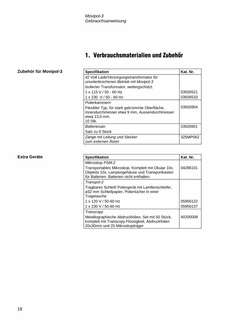
1. Verbrauchsmaterialien und Zubehör Spezifikation Kat. Nr. 42 Volt Lade/Versorgungstransformator für ununterbrochenen Betrieb mit Movipol-3 Isolierter Transformator, wettergschützt. 1 x 115 V / 50 - 60 Hz 1 x 230 V / 50 - 60 Hz
03926521 03926533
Polierkammern Flexibler Typ, für stark gekrümmte Oberfläche, Innendurchmesser etwa 9 mm, Aussendurchmesser etwa 13,5 mm. 10 Stk.
03926904
Batteriesatz Satz zu 9 Stück
03926901
Zange mit Leitung und Stecker zum externen Ätzen
325MP062
Spezifikation Kat. Nr. Mikroskop PSM-2 Transportables Mikroskop. Komplett mit Okular 10x, Objektiv 10x, Lampengehäuse und Transportkasten für Batterien. Batterien nicht enthalten.
04286101
Transpol-2 Tragbares Schleif/ Poliergerät mit Lamllenschleifer, ø32 mm Schleifpapier, Poliertücher in einer Tragetasche 1 x 120 V / 50-60 Hz 1 x 230 V / 50-60 Hz
05956122 05956137
Transcopy Metallographische Abdruckfolien, Set mit 50 Stück, komplett mit Transcopy Flüssigkeit, Abdruckfolien 20x30mm und 25 Mikroskopträger
40200008
Zubehör für Movipol-3
Extra Geräte

Movipol-3 Gebrauchsanweisung
19
2. Fehlersuche
Polierfehler lassen sich normalerweise auf folgendem Wege beheben: Prüfen Sie das Alter des angesetzten Elektrolyten. Es sollte nicht
mehr als 2-3 Monate betragen. Besonders der fertig angesetzte Elektrolyt A-2 hat eine kurze Lebensdauer von nur etwa 2 Monaten.
Prüfen Sie nach, wie viele Polituren bereits mit dem Elektrolyten durchgeführt wurden (keinesfalls mehrere Hundert pro Füllung).
Prüfen Sie nach, ob der Elektrolyt zum vorliegenden Material paßt.
Der Saugdruck der Pumpe ist in der Fabrik auf 300 " 20 mm Hg
eingestellt. Einige Materialien wie z.B. Nimonic oder Titan-Legierungen benötigen einen Durchfluß, der 400450 mm Hg entspricht. Der Saugdruck sollte am Stützen der Saugleitung (Fig. 7.3) mit einem Vakuummeter gemessen werden. Bei der Messung müssen mindestens 470 ml Flüssigkeit im Behälter sein.
Stellen Sie sicher, daß alle Verbindungen dicht sind und keine Luft in den Elektrolytfluß gesogen wird.
Mit einer Stellschraube (Fig. 7.2) kann der Saugdruck (Durchfluß) eingestellt werden. Eindrehen der Schraube erhöht den Durchfluß. Herausdrehen der Schraube vermindert den Durchfluß.
Prüfen Sie nach, ob die Kathode (Fig. 9.4) mit dem Rand des
Kopfes (ohne Polierkammer) entweder plan ist, oder etwa 0,5 mm zurücksteht.
Prüfen Sie nach, ob die eingestellte Spannung zwischen Kathode und Probe (Anode) auch tatsächlich anliegt.
Ein unsachgemäß angesetzter Elektrolyt kann einen sehr hohen Widerstand aufweisen.
Bitte beachten: Die Bilder auf die hingewiesen wird können
in dem Abschnitt Ersatzteile und Diagramme gefunden werden.
Elektrolyt
Durchfluß
Polier/Ätzkopf und Kathode

Movipol-3 Gebrauchsanweisung
20
Prüfen Sie den korrekten Sitz der Polierkammer und ihre Beweglichkeit. Falls die Kammer versprödet ist, wechseln Sie sie aus, siehe dazu Abschnitt INBETRIEBNAHME. Prüfen Sie den Ladezustand der Batterien. Prüfen Sie nach, ob die Transformatorspannung 42V "10%
beträgt.
Polierkammer
Stromversorgung

Movipol-3 Gebrauchsanweisung
21
3. Wartung Nach Gebrauch muß der Elektrolytbehälter geleert und mit Wasser gespült werden. Auch das Pumpensystem ist mit Wasser zu spülen. Dazu pumpen Sie Wasser aus dem Elektrolytbehälter durch das Pumpensystem. Falls Elektrolyt auf irgendeinen Teil des Gerätes getropft ist,
muß dieser sorgfältig abgewischt werden. Wenn aufgetropfter Elektrolyt nicht abgewischt wird und
antrocknet, kann sich auf dem Gehäuse ein farbiger Oxidfilm absetzen. Derlei Verfärbungen lassen sich mit Reinigungsmittel und einem Konservierungswachs entfernen.
Es empfiehlt sich, einmal im Jahr die Gehäuseoberfläche mit
einem Wachs zu schützen. Für die übliche Säuberung verwenden Sie ein Tuch mit mildem Spülmittel. Die mit dem Gerät gelieferten Batterien halten bei richtiger Behandlung mehrere Jahre. Eine Totalentladung schädigt die Batterien allerdings, und sie sind u.U. auszuwechseln. Bestellen Sie einen Batteriesatz (9 Stk.) bei Ihrem Struers Händler. Siehe Abschnitt VERBRAUCHSMATERIALIEN UND ZUBEHÖR.
Das Auswechseln der Batteriesicherung entnehmen Sie der Fig. 11. Entfernen Sie die 3 Halterungen (Fig. 11.3, 6 Schrauben (Fig.
11.4)). Entfernen Sie die alten Batterien Setzen Sie die neuen in genau gleicher Stellung ein. Bringen Sie die drei Halterungen wieder im Gehäuse an. Laden Sie die Batterien, wie in Abschnitt INBETRIEBNAHME
beschrieben.
Pumpe und Elektrolytbehälter Jeden Tag
Gehäuse Jeden Tag
Jede Woche
Einmal jährlich
Auswechseln der Batterien
WICHTIG Achten Sie auf richtige Polung (+Pol an )Pol), siehe Fig. 11.
Niemals beschädigte Batterien über längere Zeit im Gerät lassen.

Movipol-3 Gebrauchsanweisung
22
4. Technische Daten 220V/110V Wechselstrom, 50/60 Hz Max. 20 VA 5A 10A 2,5A Ca. 52 dB (A), gemessen in einem Abstand von 1 m/39.4” vom Gerät Max. 140 W etwa 9 mm Durchmesser Breite 410 mm Tiefe: 200 mm Höhe: 280 mm 8,8 kg (einschl. Batterien)
Netzspannung des Transformators
Leistungsaufnahme
Interne Absicherung Steuerung
Interne Batteriesicherung
Interne Transformatorsicherung Thermischer Schutzschalter
Geräusch Niveau
Polierleistung
Polishing area
Abmessungen
Gewicht

Movipol-3 Gebrauchsanweisung
23
Schnellinformation Die Oberfläche muß vorgeschliffen sein, z.B. mit Transpol-2. Wählen Sie den geeigneten Elektrolyten für das Testmaterial. Füllen Sie den Elektrolyten in den Elektrolytbehälter. Der
Flüssigkeitsspiegel muß zwischen den Marken für Min. und Max. liegen.
Den Pumpenteil in dem Behälter anbringen. Setzen Sie die komplette Einheit Pumpe/Behälter in das
Gehäuse ein. Drücken Sie von oben auf die Pumpe, bis die Einheit einrastet. Stellen Sie die Steckverbindung des Mehrpolsteckers her und
sichern Sie sie durch Aufschrauben der Kappe. Stellen Sie am Potentiometer die Spannungen für Polieren/Ätzen
ein, die dem gewünschten Strom entspricht. Stellen Sie die Polier/Ätzzeit ein. Schalten Sie die Pumpe ein. Nehmen Sie den Polier/Ätzkopf aus der Halterung. Drücken Sie die Polierkammer senkrecht und vollständig gegen
die vorbereitete Probenoberfläche. Achten Sie während des gesamten Präparationsvorganges
darauf, daß der Kopf in senkrechter Position bleibt und keine Luft in den zirkulierenden Elektrolyten gesogen wird.
Drücken Sie auf Start und der Polier/Ätzvorgang beginnt.
Einfüllen des Elektrolyten
Einsetzen des Elektrolytbehälters
Vorbereitung und Start des Polier/Ätzvorgangs
WICHTIG Den Startknopf erst drücken, wenn das Durchflußgeräusch der Zirkulation
gleichmäßig klingt.

Movipol-3 Gebrauchsanweisung
24
Zeigt das Amperemeter den gewünschten Strom an? Ist die Präparation beendet? Wenn beide LED-Anzeigen für
Polieren und Ätzen erloschen sind, heben Sie den Polierkopf/Ätzkopf von der Probe.
Stecken Sie den Polierkopf/Ätzkopf wieder in die Halterung
zurück.
Sobald der Kopf verstaut ist, schalten Sie zum Schluß die
Pumpe aus. Reinigen Sie die präparierte Stelle mit Wasser/Alkohol und
trocknen Sie sie sorgfältig. Gießen Sie den Elektrolyten in die Vorratsflasche zurück.
Benützen Sie einen Trichter dabei.
Auf was Sie bei laufendem Vorgang achten
Vorgang stoppen
Die Pumpe erst ausschalten, wenn der Polierstift in der Halterung steckt.
Reinigung von Probe und Gerät

Movipol-3Mode d’emploi
Mode d’emploi no.: 13927003
Date de parution 18.05.2009

Movipol-3 Mode d'emploi
Table des matières Page Guide de l'utilisateur ................................................... 1 Guide de référence .................................................. 17 Carte de référence rapide ........................................ 23
Toujours mentionner le n° de série et la tension/fréquence de l'appareil lors de questions techniques ou de commandes de pièces détachées. Vous trouverez le n° de série et la tension de l'appareil indiqués soit sur la page de garde du mode d'emploi, soit sur une étiquette collée ci-dessous. En cas de doute, veuillez consulter la plaque signalétique de la machine elle-même. La date et le n° de l'article du mode d'emploi peuvent également vous être demandés. Ces renseignements se trouvent sur la page de garde. Les restrictions suivantes doivent être observées. Le non respect de ces restrictions pourra entraîner une annulation des obligations légales de Struers: Mode d'emploi: Le mode d'emploi Struers ne peut être utilisé que pour l'équipement Struers pour lequel il a été spécifiquement rédigé. Manuels de maintenance: Un manuel de service de Struers ne peut être utilisé que par un technicien spécialiste autorisé par Struers. Le manuel de service ne peut être utilisé que pour l'équipement Struers pour lequel il a été spécifiquement rédigé. Struers ne sera pas tenu responsable des conséquences d'éventuelles erreurs pouvant se trouver dans le texte du mode d'emploi/illustrations. Les informations contenues dans ce mode d'emploi pourront subir des modifications ou des changements sans aucun avis préalable. Certains accessoires ou pièces détachées ne faisant pas partie de la présente version de l'équipement peuvent cependant être mentionnés dans le mode d'emploi. Le contenu de ce mode d'emploi est la propriété de Struers. Toute reproduction de ce mode d'emploi, même partielle, nécessite l'autorisation écrite de Struers. Tous droits réservés. © Struers 2009. Struers A/S Pederstrupvej 84 DK-2750 Ballerup Danemark Téléphone +45 44 600 800 Téléfax +45 44 600 801

Movipol-3 Mode d'emploi
Movipol-3 Feuille de sécurité A lire attentivement avant utilisation 1. L'opérateur doit être parfaitement instruit dans l'usage de l'appareil,
selon le Guide de l'utilisateur.
2. L'opérateur doit être parfaitement instruit dans l'usage des électrolytes utilisés avec Movipol-3.
3. Suivre les règles de sécurité en vigueur pour la manipulation, le mélange, le remplissage, le vidage et l'élimination de l'électrolyte (voir la section Précautions de sécurité). La feuille de données de sécurité du matériau (MSDS) pour chacun des électrolytes Struers peut être fournie sur demande.
4. S'assurer que la tension utilisée corresponde à la tension indiquée sur la plaque signalétique de l'appareil.
5. S'assurer que lappareil repose fermement sur son support. Si l'appareil est transporté ou pendu par la bandoullière, vérifier que la bandoullière est intacte et que le fermoir est correctement fermé.
6. Toujours vérifier que le moteur de la pompe fonctionne avant de sortir le stylet de son support.
7. Toujours conserver le stylet dans son support lorsqu'il n'est pas utilisé.
8. Ne pas laisser l'appareil sans surveillance lorsqu'il est rempli d'électrolyte.
9. S'assurer que l'appareil soit bien fixé pendant le transport et qu'il ne contienne pas d'électrolyte.
10. La tension de polissage maximum permise sur le lieu de travail doit être respectée.
L’équipement ne devra servir qu’à l’usage auquel il est destiné et ainsi que décrit en détails dans le Mode d’emploi. La machine est conçue pour être utilisée avec des articles consommables fournis par Struers. En cas de mauvais usage, d'installation incorrecte, de modification, de négligence, d'accident ou de réparation impropre, Struers n'acceptera aucune responsabilité pour les dommages causés à l'utilisateur ou à la machine. Le démontage d'une pièce quelconque de la machine, en cas d'entretien ou de réparation, doit toujours être assuré par un technicien qualifié (en électro-mécanique, électronique, mécanique, pneumatique, etc.).

Movipol-3 Mode d'emploi
Élimination Les équipements marqués d’un symbole WEEE contiennent des composants électriques et électroniques et ne doivent pas être jetés avec les ordures ménagères. Veuillez contacter les autorités locales pour toutes informations sur la procédure correcte d’élimination à suivre selon la législation nationale.

Movipol-3 Mode d'emploi
1
Guide de l'utilisateur Table des matières Page
1. Installation Vérifier le contenu de l'emballage ..................................................... 3 Placer Movipol-3 ............................................................................... 3 Se familiariser avec Movipol-3 ........................................................... 4 Alimentation en courant .................................................................... 5
Brancher le transformateur ...................................................... 5 Charger les batteries ......................................................................... 5 Connecter le moteur de la pompe et la cathode ................................ 5 Connecter l'anode ............................................................................. 5 Opérations d'attaque externe ............................................................ 5
2. Opération Utiliser les touches de contrôle ......................................................... 6
Touches du panneau frontal .................................................... 6 Fonctions de sécurité ........................................................................ 7
Coupe-circuit du moteur de la pompe ...................................... 7 Fonction de limite du courant du circuit de polissage/attaque .. 7 Coupe-circuit du circuit de polissage/d'attaque ........................ 7 Coupe-circuit en cas de sous-tension ...................................... 7
Monter le réservoir ............................................................................ 7 Démonter le réservoir ........................................................................ 7 Monter l'unité du réservoir pompe ..................................................... 8 Démonter l'unité du réservoir pompe................................................. 8 Remplir le réservoir avec l'électrolyte ................................................ 8 Vider le réservoir d'électrolyte ........................................................... 8 Monter le compartiment de polissage ................................................ 8 Commencer le processus de polissage/attaque ................................ 9 Arrêter le processus de polissage/attaque ........................................ 9 Attaque externe ............................................................................... 10 Nettoyer le réservoir et la pompe .................................................... 11 Exemples de voltage ....................................................................... 11
Fonte. 3,4% C, 0,29% Si, 0,6% Mn, 0,3% P. ......................... 11 Acier duplex ........................................................................... 11 Aluminium pur commercial 99,5% Al ..................................... 11 Acier inoxydable ..................................................................... 12 Acier à basse teneur en carbone 0,1% C ............................... 12 Acier à haute teneur en carbone ............................................ 12 Alliages de titane .................................................................... 12

Movipol-3 Mode d'emploi
2
3. Précautions de sécurité Electricité ........................................................................................ 13 Electrolytes en général .................................................................... 13 Acide perchlorique en particulier ..................................................... 14 Formation des opérateurs ............................................................... 14 Mélanger la solution ........................................................................ 14 Conserver l'acide perchlorique ou la solution .................................. 15 Risques d'incendie et d'explosion .................................................... 15 Elimination ...................................................................................... 15 Travailler sur le terrain avec Movipol-3 ............................................ 16
Endroits dangereux ................................................................ 16 Mesures de sécurité ............................................................... 16
Situations dangereuses ................................................................... 16

Movipol-3 Mode d'emploi
3
1. Installation Dans la caisse de transport se trouvent les pièces suivantes: 1 Movipol-3 avec unité de contrôle, pompe, stylet 1 Transformateur 1 Réservoir d'électrolyte 1 Fil anodique 1 Pince à anode 1 Aimant 1 Bandoulière 10 Compartiments de polissage 1 Entonnoir 1 Jeux de Mode d’emploi Movipol-3 est un appareil portable pour le polissage électrolytique sur le terrain. Si possible, l'appareil doit être placé sur un support stable. Sinon, il peut être pendu par la bandoulière dans un endroit adéquat. Pendant le transport, l'appareil ne doit pas contenir d'électrolyte et doit être maintenu de sorte qu'il ne se retourne pas.
Vérifier le contenu de l'emballage
Placer Movipol-3

Movipol-3 Mode d'emploi
4
Prendre le temps de se familiariser avec l'emplacement et les noms des composants de Movipol-3.
Interrupteur de charge/pompe Bouton de mise en marche Bouton de réglage pour la tension de polissage Bouton de réglage pour la tension d'attaque Temps de polissage Temps d'attaque Ampèremètre Indicateur de charge Indicateur de tension pour le moteur de la pompe Indicateur de polissage Indicateur d'attaque Douille de la pompe/cathode Douille de l'anode Douille pour l'attaque externe Stylet
Se familiariser avec Movipol-3

Movipol-3 Mode d'emploi
5
Brancher le câble électrique au réseau. Brancher la prise multiple de 42V au côté gauche de
Movipol-3. Quand l'interrupteur O/Charge - l/Pompe se trouve en position
supérieure, les batteries de Movipol-3 sont alors en cours de chargement. Une fois qu'elles sont entièrement chargées, l'indicateur de charge brillera en vert. Si les batteries ont besoin d'être rechargées, l'indicateur de charge s'allumera en rouge.
Bien que les batteries soient chargées à l'usine, Struers recommande de charger les batteries de Movipol-3 1 à 2 heures avant de se servir de l'appareil.
Brancher la prise multiple à la douille de l'unité de contrôle à
l'aide de l'écrou creux à chapeau. Le moteur de la pompe électrolyte et la cathode dans le stylet sont à présent connectés à l'unité de contrôle.
Placer la fiche banane du fil anodique dans la douille, Anode. La
connexion à l'échantillon est établie à l'aide de l'aimant ou de la pince joints avec l'appareil.
Pour procéder aux opérations d'attaque externe, c'est à dire en
utilisant une connexion de cathode autre que celle intégrée dans le stylet, la douille noire, une tension de sortie de 2 à 90V en courant continu, doit être utilisée comme connexion à la cathode.
Alimentation en courant IMPORTANT Vérifier que la tension électrique corresponde à la tension indiquée sur la
plaque signalétique de l'appareil.
Brancher le transformateur
Charger les batteries
ATTENTION Un jeu de batteries entièrement chargé se déchargera de lui-même en 6
mois, et une décharge complète peut causer une réduction de la longévité. Il faut donc recharger les batteries à intervalles réguliers.
IMPORTANT Lorsque le transformateur est utilisé, Movipol-3 ne doit fonctionner que
lorsque l'indicateur de charge s'allume en vert ou en jaune.
Connecter le moteur de la pompe et la cathode
Connecter l'anode
Opérations d'attaque externe

Movipol-3 Mode d'emploi
6
2. Opération
Nom Fonction Nom Fonction
O/CHARGE I/INTERRUPTEUR POMPE
Quand le réglage est sur O/Charge, les batteries sont en train d'être rechargées si l'appareil est branché au réseau électrique. Quand le réglage est sur l/Pompe, le moteur de la pompe se met en marche.
AMPEREMETRE
Pour lire l'intensité du courant lors du polissage/de l'attaque. Une plage de 0 à 2 est utilisée pour le polissage. La plage de 0 à 0,2 A est utilisée pour l'attaque. Le changement entre les plages se fait automatiquement quand les minuteries passent du polissage à l'attaque.
BOUTON DE MISE EN MARCHE
Bouton de mise en marche pour commencer le processus de polissage/attaque.
INDICATEUR DE CHARGE
Indique le niveau de charge des batteries. Lorsque branché sur courant alternatif de 42V les lectures suivantes sont possibles: Charge des batteries Niveau O/ I/ Charge Pompe Moyenne Jaune Vert Complète Vert Vert Vide Rouge Rouge
BOUTON DE REGLAGE POUR LA TENSION DE POLISSAGE
Bouton de réglage pour régler la tension de polissage. La plage de réglage est entre 10 et 90 V. La plage de tension de 60 à 90 volt en courant continu est marquée d'un avertissement.
INDICATEUR DE TENSION POUR LE MOTEUR DE LA POMPE
Indique si la tension qui alimente la pompe est suffisante: 0: l'appareil est éteint. Jaune: le moteur de la pompe fonctionne avec une tension suffisante.
Rouge: le moteur de la pompe est bloqué dû à une surcharge du moteur ou à une tension trop basse. Le circuit électrique est coupé dû à la surcharge.
BOUTON DE REGLAGE POUR LA TENSION D'ATTAQUE
Bouton de réglage pour régler la tension d'attaque.
INDICATEUR DE POLISSAGE
L'indicateur de polissage s'allume en rouge quand le processus de polissage se déroule et s'éteint une fois le processus accompli.
TEMPS DE POLISSAGE
Bouton de réglage pour régler le temps de polissage. Lorsque réglé sur ∞, le processus se déroule jusqu'à ce que le bouton soit réglé sur zéro.
INDICATEUR D'ATTAQUE
L'indicateur d'attaque s'allume en rouge lorsque le processus d'attaque se déroule et s'éteint une fois le processus accompli.
Utiliser les touches de contrôle Touches du panneau frontal

Movipol-3 Mode d'emploi
7
Nom Fonction Nom Fonction
TEMPS D'ATTAQUE
Bouton de réglage pour régler le temps d'attaque. Lorsque réglé sur ∞, le processus se déroule jusqu'à ce que le bouton soit réglé sur zéro.
DOUILLE DE LA POMPE/CATHODE
Pour connecter le moteur de la pompe et la cathode à l'unité de contrôle.
DOUILLE DE L'ANODE
Pour connecter le fil de l'anode à l'unité de contrôle.
DOUILLE POUR L'ATTAQUE EXTERNE
Pour connecter la cathode quand les opérations d'attaque externe doivent être effectuées.
Si la charge dépasse 1 A, la fonction de coupe-circuit est activée. L'indicateur de tension pour le moteur de la pompe brillera en rouge. L'appareil peut être remis en marche une fois l'erreur corrigée. En cas d'une plage de tension de 70 à 90 V, le courant est limité en rapport avec l'effet maximum des transistors (140 VA). Dans le cas d'une plage de tension de 2 -70 V à 2 A, la fonction de court-circuit est activée et un signal d'alarme retentit. Une fois l'erreur corrigée, l'appareil peut être remis en marche. En cas de surcharge, le circuit est coupé et l'indicateur de tension du moteur de la pompe brille en rouge. L'appareil peut être remis en marche après un refroidissement quand l'indicateur brille en jaune. Une sous-tension peut survenir lors de l'utilisation de batteries insuffisamment chargées. La fonction de coupe-circuit pour la sous-tension interrompra le processus et un signal d'alarme retentira. Placer la pompe dans le réservoir. Presser les boutons noirs vers le bas et les faire tourner jusqu'à
ce que les marquages soient orientés vers la pompe. Vérifier que le réservoir soit soigneusement fermé. Presser les boutons noirs vers le bas et les faire tourner jusqu'à
ce que les marquages pointent en opposé à la pompe. Un clic retentit et la pompe se dégage du réservoir.
Fonctions de sécurité Coupe-circuit du moteur de la pompe
Fonction de limite du courant du circuit de polissage/attaque
Coupe-circuit du circuit de polissage/d'attaque
Coupe-circuit en cas de sous-tension
Monter le réservoir
Démonter le réservoir

Movipol-3 Mode d'emploi
8
Abaisser l'unité du réservoir pompe dans le coffret. Presser l'unité vers le bas jusqu'à ce qu'un clic retentisse. L'unité
du réservoir pompe est alors fermée dans le coffret. Presser les deux fermetures noires sur les côtés à partir de la pompe en direction de la paroi du coffret. Un clic retentit et l'unité du réservoir pompe est démontée et peut être retirée du coffret. Avant de remplir le réservoir d'électrolyte, la section Précautions
de sécurité doit être soigneusement étudiée. Retirer la pompe et le réservoir du coffret. Retirer la pompe du réservoir d'électrolyte. Verser l'électrolyte dans le réservoir d'électrolyte. Le niveau doit
se trouver entre les marquages minimum (350 ml) et maximum (750 ml).
Monter le réservoir sur la pompe et l'unité dans le coffret de Movipol-3.
Avant de vider le réservoir d'électrolyte, la section Précautions
de sécurité doit être soigneusement étudiée. Retirer l'unité du réservoir pompe du coffret et retirer le réservoir. Si l'électrolyte doit être réutilisé, le reverser
précautionneusement dans sa bouteille. Utiliser, à cet effet, l'entonnoir fourni avec l'appareil.
Si l'électrolyte ne doit pas être réutilisé, le verser dans un réservoir adapté pour l'élimination. Respecter les règles et instructions locales en vigueur pour l'élimination.
Presser le compartiment de polissage sur le stylet jusqu'à ce
qu'il soit bien maintenu. Un compartiment de polissage a une durée de vie limitée, car le plastique durcit au contact avec l'électrolyte. Le compartiment doit être renouvelé régulièrement.
Monter l'unité du réservoir pompe
Démonter l'unité du réservoir pompe
Remplir le réservoir avec l'électrolyte
Vider le réservoir d'électrolyte
IMPORTANT Un entonnoir, des gants, un système d'aération ainsi que tout autre équipement prescrit doivent être utilisés pour le remplissage/vidage.
Monter le compartiment de polissage

Movipol-3 Mode d'emploi
9
S'assurer que le type et la quantité corrects d'électrolyte se trouvent dans le réservoir d'électrolyte. Connecter l'anode à l'échantillon à l'aide de la pince ou de
l'aimant fournis avec l'appareil. Régler la tension de polissage et le temps de polissage. Régler la tension d'attaque et le temps d'attaque. Activer le moteur de la pompe en réglant O/Charge - l/Pump en
position inférieure. Dégager le stylet de son support et le placer sur l'endroit à
préparer. Presser le stylet contre la surface en s'assurant que le
compartiment de polissage est en contact total avec la surface. Maintenir le stylet perpendiculaire (à un angle de 90°) à la
surface. L'électrolyte va alors commencer de circuler.
Appuyer sur le bouton de MISE EN MARCHE . Un "circuit
palpeur" enregistre s'il y a connexion électrique de la cathode dans le stylet à travers l'électrolyte à l'anode.
Si le circuit électrique est fermé, la minuterie commence le processus.
Lire l'ampèremètre pour vérifier si l'intensité du courant correcte
a été obtenue. Lorsque les indicateurs de polissage et d'attaque sont éteints, le
processus est achevé et le stylet doit être placé dans son support.
Une fois le stylet dans son support, éteindre le moteur de la pompe en réglant O/charge - l/Pump à O/Charge.
Nettoyer la surface polie avec de l'eau/alcool et sécher soigneusement.
Le processus de polissage/attaque peut être interrompu à tout moment lors de l'opération en réglant le bouton de réglage pour le temps de polissage/attaque sur zéro.
Commencer le processus de polissage/attaque
IMPORTANT Prendre soin qu'il n'y ait pas d'air circulant autour de la périphérie du
compartiment de polissage.
IMPORTANT Ne presser le bouton de mise en marche que lorsque le bruit fait par la
pompe indique un flux constant à travers le stylet.
Arrêter le processus de polissage/attaque

Movipol-3 Mode d'emploi
10
Après un polissage avec un électrolyte ou après un polissage mécanique, l’échantillon peut être attaqué en utilisant un électrolyte différent et la connexion d’attaque externe (accessoire pour attaque externe nécessaire). Connecter l’anode à l’échantillon à l’aide de la pince ou de
l’aimant fourni avec Movipol-3. Connecter les pinces pour l’attaque externe à la prise noire sur
Movipol-3. Régler la tension et le temps d’attaque. Utiliser les pinces pour prendre un morceau d’ouate. Tremper l’ouate dans l’électrolyte choisi (par exemple, 10%
d’acide oxalique pour l’acier inoxydable). Faire démarrer la pompe, puis le processus de polissage/
d’attaque. Badigeonner la surface de l’échantillon avec l’ouate et observer
le mouvement sur l’ampèremètre. Nettoyer l’endroit poli à l’eau/alcool et sécher soigneusement.
Attaque externe

Movipol-3 Mode d'emploi
11
Le réservoir d'électrolyte et le système de pompe doivent être nettoyés à l'eau après chaque utilisation. Vider le compartiment d'électrolyte. Remplir le réservoir d'eau et mettre la pompe en marche en
réglant O/Charge - l/Pump en position inférieure pour faire circuler l'eau à partir de réservoir d'électrolyte à travers le système de pompe.
En raison des inclusions de graphite, le polissage électrolytique n'est pas idéal, mais il est satisfaisant pour un examen "sur le terrain". La structure métallique est développée de manière excellente et seule l'apparence du graphite sera moins satisfaisante. En raison de la douceur du graphite, l'on peut remédier à cela en frottant la surface polie avec un morceau de coton humide, éventuellement avec de la Suspension d'alumine-AP FF. Prépolissage avec Transpol Jusqu'à grain 400 Electrolyte AC-2 Voltage de polissage 40V Courant de polissage 0.5A Temps de polissage 15 sec Prépolissage avec Transpol Jusqu'à grain 400 Electrolyte A-2 Polissage Voltage 35V Courant 0.7A Temps 15 sec Attaque Voltage 8V Courant 0.2A Temps 12 sec Prépolissage avec Transpol Jusqu'à grain 400 Electrolyte AC-2 Voltage de polissage 85V Courant de polissage 0.3A Temps de polissage 20 sec
Nettoyer le réservoir et la pompe
Exemples de voltage
Fonte. 3,4% C, 0,29% Si, 0,6% Mn, 0,3% P.
Acier duplex
Aluminium pur commercial 99,5% Al

Movipol-3 Mode d'emploi
12
Prépolissage avec Transpol Jusqu'à grain 400 Electrolyte E-5 Voltage de polissage 80V Courant de polissage 0.6A Temps de polissage 10 sec
Attaque ext. dans de l'oxyde oxalique 10% ou (NH)2S2O3 10%
Prépolissage avec Transpol Jusqu'à grain 400 Electrolyte A-2 Polissage Voltage 60V Courant 0.8A Temps 05 sec Attaque Voltage 10V Courant 0.18A Temps 5 sec Prépolissage avec Transpol Jusqu'à grain 220 Electrolyte A-2 Polissage Voltage 60V Courant 1.0A Temps 15 sec Attaque Voltage 3-6V Courant 0.013A Temps 3 sec Prépolissage avec Transpol Jusqu'à grain 220 Electrolyte A-3 Voltage de polissage 50V Courant de polissage 1.0A Temps de polissage 15 sec
Acier inoxydable
Acier à basse teneur en carbone 0,1% C
Acier à haute teneur en carbone
Alliages de titane

Movipol-3 Mode d'emploi
13
3. Précautions de sécurité Dans certains lieux de travail, une tension de sécurité maximum est spécifiée. Une telle plage maximum sera typiquement 42V en courant alternatif (60 en courant continu). Movipol-3 est utilisé avec un transformateur 42V en courant alternatif par un jeu de batteries rechargeables de 54V en courant continu. Movipol-3 peut être utilisé selon ces restrictions. De façon alternative, Movipol-3 peut fonctionner sur batteries seulement.
Lors de l'utilisation d'électrolytes, toutes les mesures de sécurité nécessaires doivent être prises. En dehors des mesures de sécurité indiquées ci-dessous, une fiche de données de sécurité du matériau (MSDS), fournie par Struers, pour chaque électrolyte, peut être obtenue sur demande. Il est essentiel que l'utilisateur soit pleinement instruit dans le
procédé de travail avec les électrolytes. Movipol-3 est conçue pour une utilisation avec des électrolytes
recommandés par Struers. L'emploi d'autres électrolytes, par exemple les électrolytes contenant des bases fortes ou des acides, peuvent endommager la construction ou mettre en danger la sécurité de l'utilisateur.
NOTER que grand nombre d'électrolytes contiennent de l'alcool ou
autres dissolvants inflammables. S'assurer que toutes les précautions de sécurité soient suivies lors de l'utilisation de tels électrolytes.
Lors du nettoyage de l'appareil après utilisation, s'assurer qu'il ne reste pas d'électrolyte pouvant sécher et/ou crystalliser à l'intérieur de l'appareil ou sur le matériau poli.
Il est essentiel que l'utilisateur soit parfaitement instruit dans l'utilisation de Movipol-3 et des électrolytes utilisés.
Electricité
ATTENTION Le circuit de polissage peut générer des tensions atteignant 90V en courant continu. Le bouton de réglage pour la tension de polissage indique en jaune
la plage critique entre 60 et 90V.
Electrolytes en général

Movipol-3 Mode d'emploi
14
Les électrolytes Struers comportant le préfixe A sont constitués d'environ 1 l de solution de base à laquelle de 15 à 90 ml d'acide perchlorique (60%) doivent être ajoutés. Avant de mélanger l'acide perchlorique à la solution de base, il est de grande importance de respecter les précautions de sécurité suivantes. De plus, une fiche de données du matériau (MSDS) pour l'acide perchlorique en question peut être obtenue sur demande. Tout le personnel devant se charger du mélange, de l'utilisation,
de la conservation, du transport et de l'élimination des électrolytes ou de ses composants, devra être soigneusement instruit dans les précautions à prendre pour la manipulation de l'acide perchlorique.
Toutes précautions doivent être prises contre l'inhalation des vapeurs de la solution ou de ses composants, contre le contact avec la peau, le mélange et la surcharge, et en ce qui concerne les méthodes de conservation et d'élimination.
Placer le mélange dissolvent/eau dans un bain d'eau avec
contrôle de la température. Ajouter précautionneusement l'acide perchlorique au mélange dissolvent/eau. Remuer continuellement.
Le mélange doit avoir lieu sous une hotte aérée conçue pour l'acide perchlorique.
L'utilisateur doit utiliser les vêtements et dispositifs de protection suivants: masque recouvrant entièrement la face ou lunettes de protection, gants en caoutchouc et vêtements de laboratoire ou salopette de mécanicien.
Eviter l'utilisation de tout réservoir, récipient de réaction, récipient, étagère de rangement combustible ou contenant du carbone ou tout matériau de ce type lors du travail avec cet acide.
Acide perchlorique en particulier
Formation des opérateurs
Mélanger la solution

Movipol-3 Mode d'emploi
15
Ne pas laisser de l'acide se crystalliser sur les goulots des bouteilles, chapeaux ou tout autre endroit.
Conserver dans un endroit sûr, frais et aéré dans un récipient en métal, verre ou céramique.
Maintenir à l'écart des autres produits chimiques, des matériaux combustibles et organiques.
Ne laisser, en aucune circonstance, sécher les solutions. L'acide perchlorique 60% est un produit très corrosif et oxydant.
Son chauffage peut causer une explosion et le contact avec un matériau combustible peut engendrer un incendie.
Ne combattre un éventuel incendie qu'à partir d'un endroit protégé. Eteindre par projection d'eau uniquement. Ne pas utiliser de produits chimiques secs ou de dioxyde de carbone.
Ne pas produire d'acide perchlorique anhydre, soit à partir de ses sels soit à partir de solutions aqueuses, par exemple en le chauffant avec des acides à point d'ébullition élevé ou des agents deshydratants, tels que l'acide sulphurique ou le pentoxyde de phosphore. En plus du risque d'explosion spontanée, l'acide anhydre explose instantanément au contact des matériaux organiques oxydables.
L'utilisation ou le stockage de l'acide perchlorique doit être limité à des quantités inférieures à 500 g par hotte.
Suivre les règles locales en vigueur pour l'élimination des restes et déchets. Le délayage et/ou la neutralisation sont les méthodes normalement recommandées pour l'élimination de l'électrolyte.
Conserver l'acide perchlorique ou la solution
Risques d'incendie et d'explosion
Elimination

Movipol-3 Mode d'emploi
16
Certaines mesures de sécurité doivent être prises lors du travail avec Movipol-3 sur le terrain, car certaines zones de travail peuvent être dangereuses. Ceci est le cas lors du travail dans: Des conteneurs fermés, par exemple les chaudières, les
réservoirs et les colonnes de fractionnement. Des endroits étroits tels que les fûts, les puits, les conduits et les
tunnels. Travailler dans les endroits sus-mentionnés peut s'avérer dangereux, vue que des substances toxiques peuvent s'accumuler et que l'air peut alors manquer d'oxygène. En conséquence, il est recommandé que les réservoirs ou autres endroits étroits ne restent pas ouverts ou qu'il soit interdit d'y pénétrer sans permission écrite. Des préparations et précautions de sécurité nécessaires doivent être mentionnées dans la permission et celle-ci doit être délivrée par le responsable en charge de la sécurité pour l'usine de montage ou les ateliers. Aucun processus de travail ne doit être mis en oeuvre sans cette permission. Ces précautions de sécurité et les processus indiqués pour la localisation du travail doivent être suivies. En cas de doute au sujet du contenu de cette autorisation, consulter la personne responsable. Les situations peuvent survenir lors du travail dans les endroits avec des gaz suffocants ou toxiques. Afin de s'assurer que l'air est respirable sans risque, celui-ci doit être analysé. Des imperfections dans l'isolation électrique peuvent représenter un risque de sécurité. Cependant, un procédé de travail sûr peut être effectué si les précautions de sécurité adéquates sont prises avant et pendant le travail.
Travailler sur le terrain avec Movipol-3
Endroits dangereux
Mesures de sécurité
Situations dangereuses

Movipol-3 Mode d'emploi
17
Guide de référence Table des matières Page
1. Consommables et accessoires Accessoires pour Movipol-3 ............................................................ 18 Equipement supplémentaire ............................................................ 18
2. Indication d'erreurs Electrolyte ....................................................................................... 19 Circulation ....................................................................................... 19 Stylet et cathode ............................................................................. 19 Compartiment de polissage ............................................................. 19 Alimentation en courant .................................................................. 19
3. Maintenance Pompe et réservoir d’électrolyte ...................................................... 20
Quotidienne............................................................................ 20 Coffret ............................................................................................. 20
Quotidienne............................................................................ 20 Hebdomadaire ....................................................................... 20 Annuelle ................................................................................. 20
Remplacement des batteries ........................................................... 21
4. Données techniques ........................................................... 22

Movipol-3 Mode d'emploi
18
1. Consommables et accessoires Spécification No. de cat. Transformateur de charge/alimentation de 42 Volt pour usage continu pour Movipol-3. Transformateur isolant avec caisse spéciale pour usage à l’extérieur. 1 x 115 V / 50 - 60 Hz 1 x 230 V / 50 - 60 Hz
03926521 03926533
Compartiments de polissage type flexible, pour les surfaces très incurvées, diamètre interne environ 9 mm, diamètre externe environ 13,5 mm, 10 unités.
03926904
Batteries jeu de 9.
03926901
Pinces avec fil et prise pour attaque externe.
325MP062
Spécification No. de cat. Microscope PSM-2 microscope portable. Complet avec oculaire x10, objectif x10, boîte à lumière et mallette de transport avec batteries. Les batteries ne sont pas inclues.
04286101
Transpol-2 appareil portable pour le prépolissage et le polissage non-destructifs. Complet avec câble flexible, moteur courant continu, poignée droite, poignée en angle droit. 1 x 120 V / 50-60 Hz 1 x 230 V / 50-60 Hz
05956122 05956137
Transcopy réplique métallographique réflective, jeu de 50. Complet avec fluide Transcopy, feuilles de réplique 20 x 30 mm et 25 lames de microscope.
40200008
Accessoires pour Movipol-3
Equipement supplémentaire

Movipol-3 Mode d'emploi
19
2. Indication d'erreurs
En cas de défauts de polissage, ces défauts peuvent normalement être corrigés à l'aide du schéma d'indication d'erreurs suivant: Vérifier l’âge de l’électrolyte mélangé. Il ne doit pas avoir plus de
2 ou 3 mois. L’électrolyte A-2 en particulier a une longévité limitée (environ 2 mois) une fois mélangé.
Vérifier le nombre de polissages réalisés avec l’électrolyte. Il ne doit pas être utilise pour plusieurs centaines de polissages.
Contrôler qu'une combinaison d'électrolyte et de matériau correcte est utilisée.
L'aspiration de la pompe est réglée à 300 " 20 mm Hg à l'usine
(certains matériaux, tels que le Nimonic et les alliages de titane nécessitent une circulation de 400 à 450 mm Hg). L'aspiration est mesurée à l'aide d'un vacuomètre par l'embout du tuyau d'aspiration (fig. 7.3).
Il doit rester 450 ml de liquide dans chaque unité. Vérifier que tous les branchements sont bien étanches et que de
l'air n'est pas aspiré dans le courant d’électrolyte. L'aspiration de la pompe (circulation) peut être réglée à l'aide de la vis (fig. 7.2). Visser vers l’intérieur augmente la circulation, visser vers l’extérieur diminue la circulation.
Contrôler que la cathode (fig. 9.4) est au même niveau, ou à
environ 0,5 mm du bord de la pointe du stylet, sans compter le compartiment de polissage.
Vérifier que la tension préréglée peut être établie entre la cathode et l’échantillon (l'anode).
La résistance peut être très élevée dans un électrolyte qui n'a pas été mélangé correctement.
Vérifier que le compartiment de polissage est correctement monté et toujours flexible. S'il n'est pas flexible, remplacer le compartiment, voir la section INSTALLATION. Vérifier que les batteries sont rechargées. Contrôler que le transformateur de tension est de 42 V " 10%.
Noter: Les chiffres auxquels ce Mode d’emploi fait référence sont indiqués à la section Spare Parts and Diagrams.
Electrolyte
Circulation
Stylet et cathode
Compartiment de polissage
Alimentation en courant

Movipol-3 Mode d'emploi
20
3. Maintenance Le réservoir d’électrolyte doit être vide et rincé à l'eau après utilisation. Le système de pompe doit aussi être rincé. Pour cela, faire circuler de l'eau à partir du réservoir d’électrolyte à travers le système de pompe. Si de l’électrolyte s'est répandue sur la plaque avant ou sur une
autre partie du coffret, il faut l'essuyer. L’électrolyte usé contient des éléments de métal dissous
dérivant des échantillons polis/attaqués. Une pellicule colorée d'oxyde de métal peut se développer sur la surface du coffret si des restes d’électrolyte sèchent sur le coffret. De telles décolorations peuvent être éliminées à l'aide de détergents ou de cire spéciale pour voitures ou bateaux en fibres de verre.
Nous recommandons de traiter la surface du coffret à la cire une
fois par an pour la préserver. Pour un nettoyage d'ordre général, utiliser un chiffon avec un léger détergent.
Pompe et réservoir d’électrolyte Quotidienne
Coffret Quotidienne
Hebdomadaire
Annuelle

Movipol-3 Mode d'emploi
21
Les batteries jointes dureront plusieurs années si elles sont utilisées correctement. Cependant, si elles sont totalement déchargées, elles pourront être endommagées et devoir être remplacées. Un jeu de batteries (9 batteries) peut être commandé chez les représentants Struers, voir section CONSOMMABLES ET ACCESSOIRES.
Suivre la procédure de remplacement du fusible de batterie, voir fig. 11: Retirer les 3 glissières (fig. 11.3, 6 vis (fig. 11.4)). Déconnecter les vieilles batteries et les retirer. Placer les nouvelles batteries exactement dans la même position
que les anciennes. Replacer les 3 glissières et le coffret. Recharger les batteries, voir section INSTALLATION.
Remplacement des batteries
IMPORTANT Prendre soin que tous les branchements soient corrects
(pôle + à pôle -), voir fig. 11. Ne jamais laisser des batteries endommagées pendant
trop longtemps dans l'appareil.

Movipol-3 Mode d'emploi
22
4. Données techniques 220V/110V (courant alternatif), 50/60Hz Max. 20 VA 5A 10A 2,5A Env. 52 dB (A), mesuré à une distance of 1 m/39,4” de la machine. Max. 140W Environ 9 mm de diam. Largeur: 410 mm Profondeur: 200 mm Hauteur: 280 mm 8,8 kg (batteries inclues)
Alimentation en courant du transformateur
Consommation en courant
Fusible du circuit interne
Fusible du transformateur interne
Fusible des batteries Protection interne thermique automatique
Niveau de bruit
Courant de polissage
Superficie de polissage
Dimensions
Poids

Movipol-3 Mode d'emploi
23
Référence rapide La surface doit avoir subi un prépolissage plan, par ex. sur
Transpol. Choisir l'électrolyte correct pour le matériau de test. Verser l'électrolyte dans le réservoir d'électrolyte. Le niveau du
liquide doit se trouver entre les marquages minimum et maximum.
Placer la pompe dans le réservoir. Abaisser le dispositif pompe/réservoir dans le coffret. Appuyer sur la partie supérieure jusqu'à ce que le dispositif soit
fermé. Brancher la prise multiple dans la fiche sur la plaque avant et
serrer le boulon. Régler les deux tensions sur l’échelle à une tension
correspondant à l’intensité désirée. Régler les temps de polissage et d'attaque. Mettre la pompe en marche. Sortir le stylet de son support. Appuyer le stylet contre la surface préparée de l’échantillon en
s'assurant que le compartiment de polissage soit bien en contact avec la surface.
Maintenir le stylet perpendiculairement (à un angle de 90º) par rapport à la surface durant tout le processus. L'électrolyte commence à circuler. Prendre soin qu'aucun air ne passe dans la périphérie du compartiment de polissage.
Appuyer sur le bouton de mise en marche et le processus (polissage/attaque) se met en route.
Remplissage de l'électrolyte
Montage du réservoir électrolyte
Activer le processus
IMPORTANT Ne presser le bouton de mise en marche que lorsque le bruit provenant de
la pompe indique que le courant dans le stylet est constant.

Movipol-3 Mode d'emploi
24
Lire l’ampèremètre pour vérifier que l’intensité du courant correcte a été obtenue.
Quand les indicateurs luminodiodes pour le Polissage et l'Attaque s’éteignent, retirer le stylet de l’échantillon.
Placer le stylet dans son support. Le presser légèrement vers le
bas.
Quand le stylet est bien placé dans son support, éteindre la
pompe. Nettoyer la zone préparée avec de l'eau/de l'alcool et sécher
soigneusement. Reverser électrolyte dans sa bouteille. Utiliser l'entonnoir prévu à
cet effet.
Surveillance du processus
Arrêter le processus
Ne pas éteindre la pompe avant que le stylet ne soit remis dans son support.
Nettoyer l'appareil

Manual No.: 13927003
Date of Release 16.11.2005
Movipol-3Spare Parts and Diagrams
updated 16.12.2009

Movipol-3 Spare Parts and Diagrams
Always state Serial No and Voltage/frequency if you have technical questions or when ordering spare parts.
The following restrictions should be observed, as violation of the restrictions may cause cancellation of Struers legal obligations: Instruction Manuals: Struers Instruction Manual may only be used in connection with Struers equipment covered by the Instruction Manual. Service Manuals: Struers Service Manual may only be used by a trained technician authorised by Struers. The Service Manual may only be used in connection with Struers equipment covered by the Service Manual. Struers assumes no responsibility for errors in the manual text/illustrations. The information in this manual is subject to changes without notice. The manual may mention accessories or parts not included in the present version of the equipment. The contents of this manual is the property of Struers. Reproduction of any part of this manual without the written permission of Struers is not allowed. All rights reserved. © Struers 2009. Struers A/S Pederstrupvej 84 DK-2750 Ballerup Denmark Telephone +45 44 600 800 Telefax: +45 44 600 801

Movipol-3 Spare Parts and Diagrams
1
Table of contents Drawing Fig. 1 Movipol-3, complete Fig. 2 Movipol-3, details ........................................... 13920003 Fig. 3 Supply transformer ......................................... 14440002G Fig. 5 Battery fuse exchange Fig. 6 Pump and electrolyte container .............. 13920202 (1 of 2) Fig. 7 Pump and container, cross section ......... 13920202 (2 of 2) Fig. 8 Control panel .................................................. 13920382 Fig. 9 Pencil, cross section ...................................... 13920152 Fig. 10 Securing the shoulder strap Fig. 11 Batteries ......................................................... 13820018 Fig. 12 Motor connection ........................................... 13920275 Fig. 13 Wiring diagram ............................................... 13920295C Fig. 14 Wiring diagram, pump unit ............................. 13920017C Fig. 15 Component illustration control board ............. 13920101 Fig. 16 Circuit diagram control board, A2 .................. 13920102A Fig. 17 SMPS-board component illustration .............. 13920290D Fig. 18 Polishing/etching volt. circuit .......................... 13920291D Fig. 19 Charge circuit ................................................. 13920294B Fig. 20 Simplified 24V pump motor circuit ................. 13920128B Fig. 21 Simplified polishing/etching voltage ............... 13920293 Fig. 22 Test of V5 and V7 .......................................... 13920125 Fig. 23 Pump motor circuit, A1 ................................... 13920292C
Some of the drawings may contain position numbers not used in connection with this manual.

Movipol-3 Spare Parts and Diagrams
2
Pos. and Description Cat. No.
Fig. 1 Movipol-3, Complete

Movipol-3 Spare Parts and Diagrams
3
Pos. and Description Cat. No.
5 3-pole socket 99-0211-30-04....................................392MP065 5 Socket cover 08-0201-28-00 ....................................392MP066 6 Hub for handle ........................................................392MP007 6 Handle bushing.......................................................392MP008 6 Collar bushing, 1 pc. Disc 15 x 21 x 2.5 mm, 1 pc. Screw MC 5 x 8 SS, 1 pc. Disc no. 8, 1 pc. Disc CW 10, 1 pc. Korrex button SW4, 1 pc. .......................................392MP011 7 Fixture for shoulder strap ......................................392MP009 8 Handle, complete ....................................................392MP003 8 Stanchion ................................................................392MP010 9 Lock-pin, 1 pc. Disc M8, 1 pc. Top nut M8, 1 pc. ....................................................392MP012 10 Screw cap EFV 3/4".................................................392MP016 11 Lock washer ............................................................392MP017 12 Cabinet, upper part ................................................392MP002 13 Base .........................................................................392MP001 14 Stub for flex hose ....................................................392MP018 Container holder .....................................................392MP019 Spring suspension...................................................392MP020 Spring......................................................................392MP021 Clamp, complete .....................................................130MP038 Magnet, complete....................................................130MP039 Anode wire, complete..............................................392MP070
Fig. 2 Movipol-3, Details Drawing 13920003

Movipol-3 Spare Parts and Diagrams
4
Pos. and Description Cat. No. 3-pole transformer plug 692-2-99-0210-29-04 .................. 392MP0064
Fig. 3 Supply transformer Drawing 14440002

Movipol-3 Spare Parts and Diagrams
5
Pos. and Description Cat. No.
ENGLISH Battery Fuse Exchange
Remove the pump assembly including the electrolyte container
Lay down Movipol-3 on the side. Unscrew the 4 assembly screws
in the bottom frame. Slide the bottom frame to the
normal horizontal position. Exchange the 10A fuse in the
fuse holder next to the batteries. Reassemble the cabinet.
DEUTSCH Austauschen
der Batteriesicherung Das Pumpenaggregat einschließ-
lich des Elektrolytbehälters ent-fernen.
Movipol-3 auf die Seite legen. Die 4 Montierungsschrauben
des Bodenrames lösen. Den Bodenrahmen bis zur norma-
len horizontalen Position schieben. Die 10A Sicherung im Batterie-
halter neben den Batterien aus-tauschen.
Das Gehäuse wieder montieren.
FRANÇAIS Remplacement du fusible
des batteries Enlever l’unitè de pompe et la
cuve d’èlectrolyte. Coucher Movipol-3 sur le côtè. Dèvisser les 4 vis d’assemblage
dans le cadre de fond. Faire glisser le cadre de fond
jusqu’à sa position horizontale. Remplacer le fusible 10A dans
le porte-fusible près des batteries. Rassembler le coffret.
Pos. and Description Cat. No
2 Fuse 10AT (10 pcs.).................................................392MP075 3 MOVAB, Set of batteries ..........................................03926901
Fig. 5 Battery fuse exchange

Movipol-3 Spare Parts and Diagrams
6
Pos. and Description Cat. No.
1 ELMA wing button 023-3325 ELMA lid 040-3625.................................................392MP006
3 Eccentric, 1 pc. Axle, 1 pc. Comp. spring, 1 pc. Disc M4, 1 pc. Nut M4, 1 pc............................................................392MP013
4 Locking pawl Comp. spring...........................................................392MP014
5 Pencil holder ...........................................................392MP026 6 Pump assembly platform........................................392MP027 8 Locking plate...........................................................392MP015
Fig. 6 Pump and Electrolyte Container
Drawing 13920202 (1 of 2)

Movipol-3 Spare Parts and Diagrams
7
Pos. and Description Cat. No. Pump, complete (with pencil)................................... R3920202 Pump, complete (without pencil) .............................. 13920202 3 Return pipe socket................................................... 392MP029 4 Hose connection ......................................................... 13920155 5A Pump house with return pipe
Hose 1/8" x 20 mm Screw M3 x 8 + nut M3 Screw M4 x 20.......................................................... 392MP036
5B Return pipe ................................................................ 13920251 6 Glass disc ................................................................. 392MP037 7 Glass disc spring...................................................... 392MP038
Vane wheel Vane wheel roller, 3 pcs. ......................................... 392MP039
8 Electrolyte container ............................................... 392MP040 9 Handle 1307/20B-M5............................................... 392MP041 10 Motor flange............................................................. 392MP044 11 Spacer bushing
O-ring 5.3 x 2.4 ........................................................ 392MP045 12 Sling disc.................................................................. 392MP046
Gasket flange ........................................................... 392MP047 13 Pump axle ................................................................ 392MP048 13 Cyl. Pin 2x10 A4 (30 pcs) .........................................RZS11210 15 Set of seals 14 a V-ring VS 008, 1 pcs. 15 b O-ring 108 x 4, 1 pcs. 9.20 c O-ring 15 x 2, Viton, 1 pcs. 9.40 d O-ring 4.48 x 1.78, Viton, 4 pcs. ........................... 392MP78 17 PVC hose 5/32" x 20 mm, 1 pcs. ..............................RNU19305 20 Air tube, complete ..................................................... 13920258 21 Axle house................................................................ 392MP035 22 Motor screen lid ....................................................... 392MP050 23 Motor screen .............................................................. 13929005 24 Motor ........................................................................ 392MP042 25 Feed pipe, complete ................................................. 392MP034 26 Spring......................................................................... 13140108
Fig. 7 Pump and Container, Cross Section
Drawing 13920202 (2 of 2)

Movipol-3 Spare Parts and Diagrams
8
(Fig. 7, Drawing 13920202 (2 of 2), Pump and Container, Cross Section)

Movipol-3 Spare Parts and Diagrams
9
Pos. and Description Cat. No.
1 Switch with cover U 851.........................................213MP002 2 Push button 18235, ................................................392MP071 Cover U 224.............................................................391MP006 5 Ammeter KM6 ........................................................392MP053 Ammeter bracket ....................................................392MP069 10 4-pole socket 09-0112-00-04....................................2XM00112 Socket cover 08-0044-00-12 ....................................2XM90044 Control PCB 205-P-395/1 A2 ..................................392MP060 Tape cable ...............................................................392MP061 SMPS-board 205-P-3041 A1 ...................................392MP062 11 Banana socket, red ................................................. 2XG08751 Tongs with wire and plug .......................................325MP062 12 Banana socket, black .............................................. 2XG08750 Terminal strip 25.600.1253 ....................................392MP057 13 Front plate, Movipol-3 ..............................................13922901 14 ELMA button 020-4425, 1 pcs. ELMA lid 040-4025, 1 pcs. ELMA wing disc 041-4025, 1 pcs. V-ring VS-0007NBR60, 1 pcs. ................................392MP005
Fig. 8 Control panel Drawing 13920382

Movipol-3 Spare Parts and Diagrams
10
Pos. and Description Cat. No.
Pencil, complete ......................................................392MP022 2 Polishing Chamber, short 14mmxr8 ........................13920323 10 Pencil casing .............................................................13920156 20 O-ring Ø15.00x2.00, part of Set of Seals................392MP078 30 Pencil pipe stub.........................................................13920153 40 O-ring Ø4.48x1.78 (10 pcs.) ....................................375MP037 40 O-ring Ø4.48x1.78, part of set of sealing ...............392MP078 70 Pencil hoses, complete with
Cathode wire, 1 pcs. Hose 1.8" x 1200, 2 pcs. Flex hose, 1 pcs. ......................................................392MP033
Red cathode wire, complete with banana plugs.....392MP068 90 Pencil handle.............................................................13920158 100 Cathode pipe with O-rings......................................392MP028 110 Cover A ø14.5 ELMA ..............................................2GD53025
Fig. 9 Pencil, Cross Section Drawing 13920152

Movipol-3 Spare Parts and Diagrams
11
Pos. and Description Cat. No.
4 Strap........................................................................392MP074 Fig. 10 Shoulder Strap

Movipol-3 Spare Parts and Diagrams
12
Pos. and Description Cat. No.
2 Fuse holder .............................................................392MP067 2 Battery Fuse, 10 A (10 pcs) ....................................392MP075 3 Rail (3 pcs)...............................................................392MP072 4 Phillips screw & Disc M4, 7 pcs. ............................392MP073
Fig. 11 Batteries Drawing 13920018

Movipol-3 Spare Parts and Diagrams
13
Pos. and Description Cat. No.
1 4-pole plug 09-0109-1004........................................392MP063 2 Motor PCB 205 P 308, incl. cable with plug...........392MP043
Fig. 12 Motor Connection Drawing 13920275


Kontcikt og pot. metreskcit monteres -moMec-e.svinkeiret pa print.

X5: 1612V in )—
Trig. Blok.Signat
Pumpenmotorüberlust SignaLPump Motor _______________________________Overload Signal
02Reset X5:7
14 USMPS - Error ~ 1 74HC14Signal 1Oj~/~6V
S.M.PS. Fehter-signal
X515ov In )—
Trigger nhibit+ 12V
Free JQ\/( ~X5:2~R21 15V~ ~
_________________ : 20V
v102k _~~io BC 1688
iN4148YB~1~
E~i R25 _L ~+6V
Hi ______ .II~1 — _________ [~mpI~ed ......L. yeUOw
-~D, 409310
acoustic alarm timer alarm on/offTimer für Schattgeber timer
+12V +12V R22 R43
geber
,12V~
R32 auf/zu Zejt~R33 R231% Time Adj.
R24 Vii~-6 r.~M3SS
.‘~..‘ 7+
~ N2
Pot.IEtch.-Time setPot/Atse - zeit Einstelter
Charge Lade-ndicator indikcitor
for PoUsh. time seto L5s.adj. to t O35s.
(TP1)
PoLiezeit Einstel Lenauf tr~-=O,35s.
(TP1)
409374HC14
• 6V
0) 0 c~
osc~Lator * counterOsc + Zähler
+ 12V
R 141%
4016 D33 _________
R39 1%
R16 terrn.5
4016 D3
R40 ____ 213
t~m12
~R13 R15
PoL/Ekch, - VoLtage setPoL/Atse — spann. E~nsteLler
X5~1
+ 5v
1+6V
Start c~
10 14 5 02 1NI.148re~ 1 i ~ 74HC1~
-~_ __out.11312 556 R7~ Ni_~ ~ __
out.
556 ~~i~H5 ~JR11
1c4J~ J~eePer
74HG 14R8
11O~/16v ~oflshing~
C15
6 01 V3 ~red
8C2588
P/.5
green
.12V~ 74HC14 A- meter
Controt Sign,
tt
R38V6~
(‘aC2588 R2 1P1\AR37 ~ D2 Clock
timeJm10 ~.
ft~1hii~ 7~HC14 trigC13 L__..J
LC6
2357
‘1’
* 12V
~ R 27
R41
2240
86128 15
OL j~1R2O
PolishingSec. J
EtchingSec.
03 ~oie
9 12
cg
/TPo
term. 5
8C1688 1
‘/4 R3~D3 4016
~1O
28
t~o TNt~2Os-}_~_p;-ET 1 w 496 282 m 524 282 l S BT
t=oo _____
1PoL~shi~~VoLt. J
Etching
VoLt.1~j—* t~rn~13
V~35,
Etch,
Pot. P
PoL time Etch. tfrne~
128 tp 86 t~
‘set X5:11
LM358 IBC 168B
V2
12 I
~ R29
R18 ~ ~~~ö~n6v
1N4 148
R31
X5:6
X5~8 gree~red
X5:1O
—.4~ 2~.1.fl twa ~:\~~/M~e~o~Movipol-2 GBID 2O5~P-3O5/1
~TPI ~DQ Al~, i i i~ji~i i~j 5 oao ~~(j S7
At~endeS type EntaIte,’
Circuit Diagram ControL Board A2 3920102 i~Schattptcin Steuer KreisLauf
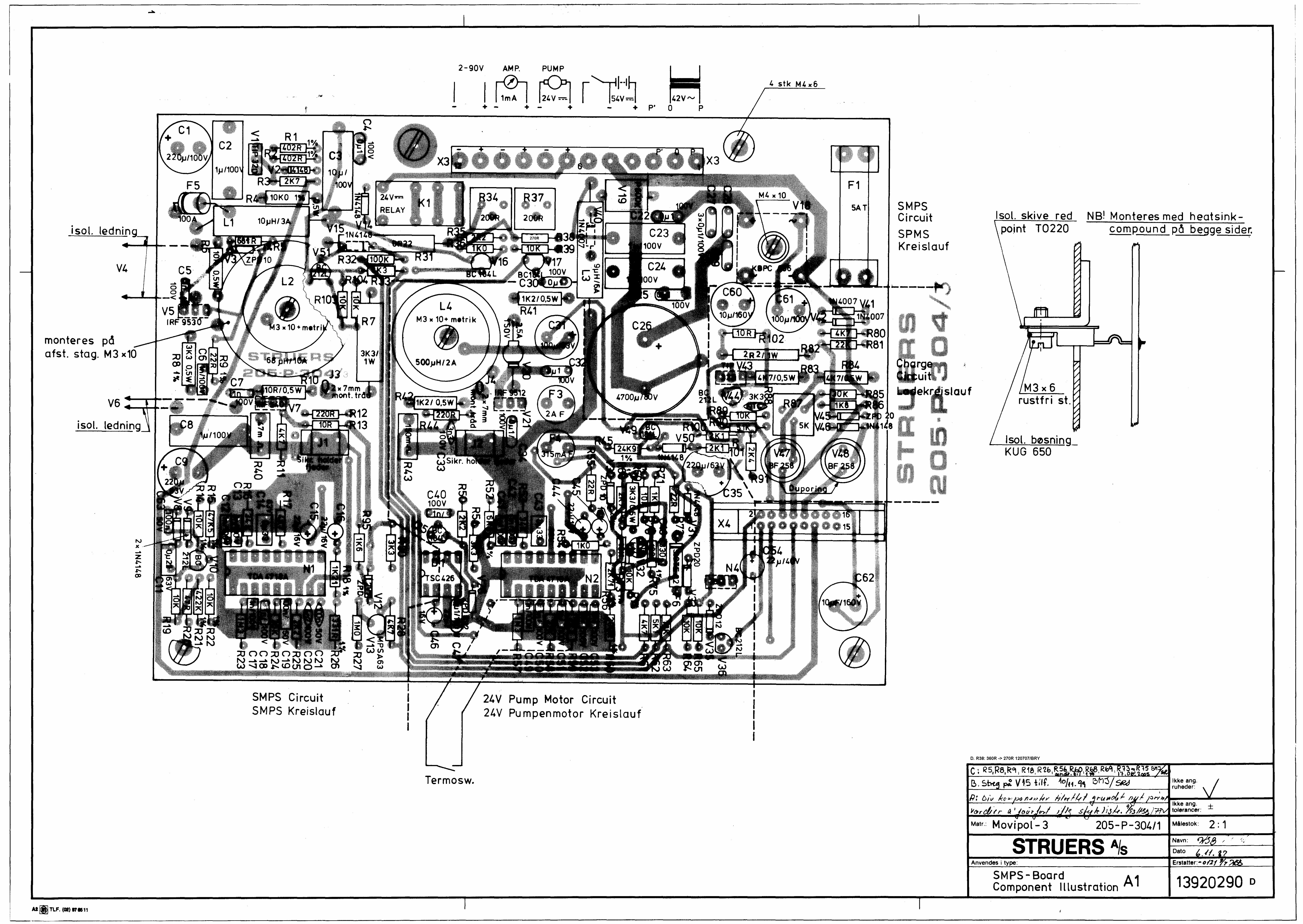


>CT,-4A>Q(0
II
>(N
1’
Im
k~OP~sbq~ktfl~ ~°~o493 ~ ~~ ?k&~,~J<~“9o~~
•Matr. GB/D Movipo —Mâ~estok: OverfladebehandL:
~TDI ‘ERg A/I I 1 ~ a’ S
Navn’ ~/~‘ ~‘ —
Dato 17~i~S?
Kode: Any. type: Erst.:
SimpL2LN Pump Motor CircuitSimpL24V Pumpen motor Kreis~ouf~
M~TLF ~‘ 97~nl

RE=1OO-~->
> ~ >N.ci (C
GB! D MovipoL —2 M~estok: OverfladebehandL.:
STRUE Al~S
Navn:
Dato
Kode: Any. i type’ -______ Erst.: -o/27 r92I~ ~
‘Simp(. PoL/Etc.Voltcige CircuitSimpi. Pol./Atzen Spann. Kreistauf
M~1LF %~97*55

T I
Al
kke ang.~er:
Ikkeang. ±tolerancer: —
Matr Movi poL — 2Mâlestok: Overfiadebehandi
STRUERS A/sNavn. ws~/~
Dato 17~ff~7
Kode: I Any. type:
Test of V5 og V7Erst.:
3920125
500
A4~TLF,l~)97~51


eu_erkl\392f.doc
Dansk Overensstemmelseserklæring SFabrikant Struers A/S
Pederstrupvej 84 DK-2750 Ballerup, Danmark Telefon 44 600 800
erklærer herved, at Produktnavn: Movipol-3 Type nr.: 392 Maskintype: Elektrolytisk polerapparat
er i overensstemmelse med følgende EU-direktiver:
EMC-direktivet 2004/108/EF efter følgende norm(er): EN61000-6-1:2002, EN61000-6-3:2002.
Supplerende oplysninger
Endvidere overholdes de amerikanske normer: FCC part 15, subpart B
Ovenstående overensstemmelse(r) er erklæret iflg. den globale metode, modul A
Dato: 04.12.2007 Christian Skjold Heyde, Vice President, Udvikling og Produktion, Struers A/S
English Declaration of Conformity SManufacturer Struers A/S
Pederstrupvej 84 DK-2750 Ballerup, Denmark Telephone +45 44 600 800
Herewith declares that Product Name: Movipol-3 Type No: 392 Machine Type: Electrolytic polishing apparatus
is in conformity with the provisions of the following directives:
EMC-Directive 2004/108/EEC according to the following standard(s): EN61000-6-1:2002, EN61000-6-3:2002.
Supplementary Information
The equipment complies with the American standards: FCC part 15, subpart B
The above has been declared according to the global method, module A
Date: 04.12.2007 Christian Skjold Heyde, Vice President, R& D and Production, Struers A/S

eu_erkl\392f.doc
Deutsch Konformitätserklärung SHersteller Struers A/S
Pederstrupvej 84 DK-2750 Ballerup, Danmark Telefon +45 44 600 800
erklärt hiermit, daß Produktname: Movipol-3 Typennr.: 392 Maschinenart: Elektrolytisches Poliergerät
konform ist mit den einschlägigen EG-Richtlinien
EMC-Direktive 2004/108/EWG gemäß folgender Normen: EN61000-6-1:2002, EN61000-6-3:2002.
Ergänzungs-information Die Maschine entspricht ebenfalls den amerikanischen FCC Normen: FCC Teil 15, Abschnitt B
Die obenstehende Konformität ist in Folge der globalen Methode, Modul A erklärt
Datum: 04.12.2007 Christian Skjold Heyde, Stellvertretender Geschäftsführer, Entwicklung und Produktion, Struers A/S
Français Déclaration de conformité SFabricant Struers A/S
Pederstrupvej 84 DK-2750 Ballerup, Denmark Téléphone +45 44 600 800
Déclare ci-après que Nom du produit: Movipol-3 Type no: 392 Type de machine: Appareil de polissage électrolytique
est conforme aux dispositions des Directives CEE suivantes:
Directive EMC t 2004/108/CEE conforme aux normes suivantes: EN61000-6-1:2002, EN61000-6-3:2002.
Informations supplémentaires
L’équipement est conforme aux standards américains: FCC paragraphe 15, sous-paragraphe B
La déclaration ci-dessus a été faite d’après la méthode globale, module A
Date: 04.12.2007 Christian Skjold Heyde, Vice- President, R& D et Production, Struers A/S

On-site materialographic preparation and examination
Conventional materialographic preparation entails cutting a sample from a material. This method is not always appropriate as it destroys the component which is being examined.
Many applications require the ability to perform a materialographic preparation and examination without ensuing damage to the subject. The non-destructive method is used in these cases.
The usual preparation steps such as grinding, polishing and etching are performed on the part to be examined in a limited area where no damage can be done, whereupon the surface can be analysed.
On-site preparation is particularly suitable for quality checks in power stations, oil platforms, bridges, aircraft etc. The non-destructive preparation method enables the necessary inspection to be carried out on site.
Struers manufactures a complete range of portable equipment for non- destructive preparation, from basic grinding through mechanical and electrolytic pol-ishing to electrolytic etching. The range also includes a portable microscope for on-site use and methods for producing replicas of the prepared surface.
Using replica methods makes it possible to perform the microscopic examination in the laboratory - under perfect working conditions.
The entire Struers non-destructive prep-aration range has been designed for field work. The equipment is thus as compact and as light as possible. It is easy to transport and can be used literally under any conditions.
Non-destructive preparation

Transpol-2 - Mechanical grinding and polishing under all working conditionsTranspol-2 is a portable grinding and pol-ishing apparatus. It is extremely compact and is designed for field work under even the most difficult conditions. Transpol-2 fits into a practical shoulder bag with all the necessary accessories and weighs an approximate total of only 5 kg.Transpol-2 consists primarily of 2 parts: a control unit and a grinding and polish-ing unit. The control unit comprises the power supply and speed regulator unit (100-7000 rpm). The grinding and pol-ishing unit is connected to the control unit by a soft, flexible cable. It consists of a direct current motor with a holder with an easily exchangeable rubber disc, upon which the grinding paper and polishing cloth are mounted.
Transpol-2 is available with two types of holder: one for straight mounting and one for right-angle mounting, thus mak-ing it possible to use Transpol-2 in even the most inaccessible places.
Transpol-2 Movipol-3
GrindingTranspol-2 uses 32 mm diameter SiC grinding paper discs in grit sizes 60, 120, 240 and 500#. Transpol-2 also includes a special flapper wheel for grinding of extremely uneven surfaces.
PolishingTranspol-2 uses DP-Dac, DP-Dur, DP-Mol, DP-Nap and OP-Felt polishing cloths, all 32 mm diameter, and DP-Paste, DP-Stick or DP-Spray. Trans-pol-2 is furthermore delivered with a special felt cone for polishing of uneven and curved surfaces.
All the necessary accessories are contained in Transpol-2’s carrying case.
Movipol-3 - Electrolytic polishing and etching in the field Movipol-3 is a portable electrolytic metal polishing and etching apparatus. It is ex-tremely compact and robust and can be used anywhere. Electrolytic preparation is a particularly fast and efficient method of non-destructive metallographic prepa-ration. It can be applied directly to critical surfaces and is widely used for metal safety inspection, especially for critical parts of larger units, e.g. for welds and other joints. The method effectively re-veals changes in the microstructure of the metal and allows to prevent possible damage because of cracks and leaks.
Automatic polishing and etchingMovipol-3 consists of a compact unit comprising the power supply, control unit, pump motor, electrolyte container and polishing unit. When the polishing unit is pressed against the metal surface, an electrolytic reaction is started. After 5-10 seconds of use, the prepared area is as reflective as a mirror and etching can commence.
Due to the special design of the
polishing pencil, electrolytic
polishing with Movipol-3 is quick and uncomplicated

The entire process is automatic: after completion of the polishing, Movipol-3 proceeds to the etching process. When this is finished, the unit emits an audio signal. In less than one minute a surface is obtained which is ready for analysis, either on-site or by means of replica for laboratory examination.
Complete FreedomMovipol-3 is equipped with recharge-able batteries and supply transformer. In other words, the apparatus is as suitable for stationary laboratory work as it is for field work, depending on the require-ments.
PSM-2 Transcopy
PSM-2 - Fast and easy microscopy outside the laboratoryPSM-2 is a small, portable microscope for use in the field. It is battery-powered and provides magnifications of 100 x, 200 x and 400 x. PSM-2 comes in a shoulder bag which also contains the batteries.
PSM-2 is particularly suitable for pre-liminary examination of the prepared surface. A replica is recommended if a more detailed analysis is required. PSM-2 is highly suitable for preliminary replica examinations when used together with Transpol-2 and Movipol-3.
Transcopy Replica FoilTranscopy Replica Foil is used to make a replica of any polished and etched surface. It is especially used if on-site analysis using a portable microscope is not sufficient or if micrographs of the prepared structure are required. Trans-copy Replica Foil creates a permanent replication of microstructures, cracks and defects for future analysis and compari-son in the laboratory.
FunctionTranscopy Replica Foil consists of reflect-ing plastic film with a self-adhesive back. A replica is made by applying Transcopy fluid to the film and pressing it firmly onto the prepared and etched surface. A slightly over etched structure results in a higher contrast of the replica. After 4-5 minutes the foil is removed from the surface. By removing the cover paper, the replica can be adhered to a plain plate and then examined under an optical mi-croscope.
With Transcopy, Replica foil, replicas can be taken on the spot for subsequent examination in the laboratory.
PSM-2 and Transcopy constitute an indispensable tool for non-destructive materialography.
Transcopy

An operator dispenses RepliSet onto a sample, and then peels off the cured replica.
Pure copper. Sample etched with cupric chloride and ammonia. Magnification 100 x
Sample Replica
RepliSet 50 ml system.
RepliSet
The RepliSet system is designed to produce an exact 3D copy of a surface. It is used for non-destructive testing and field applications allowing the structure or irregularities on critical components to be examined and measured under labo-ratory conditions.
RepliSet is a specially formulated fast curing two-part silicone rubber with a good releasing ability for flexible high-resolution 3D replicas, which behave like a metallic surface when examined in an optical microscope.RepliSet compounds are supplied in car-tridges and are dispensed using a hand-operated dispensing gun. The cartridges contain both polymer and curing agent, which are automatically mixed in a dis-posable static-mixing nozzle during ap-plication to the surface. The application system offers superior and fast results, regardless of the conditions.
RepliFix is a less advanced parallel to RepliSet. RepliFix and RepliSet are designed to bond together. The two com-ponents are mixed and applied by hand. RepliFix is used as support for RepliSet or as a stand alone product for moulding of surface shape for low tech applica-tions.A backing slide bonds to the RepliSet or RepliFix replica. The backing slide serves to maintain the original profile and en-sures a flat back to the replica.
A replica can be taken from all metallic materials and most other solid materials like ceramics, plastics and glass. There are no size, shape or thickness limita-tions on the replicas that can be made and it is even possible to take replicas from othervise inaccessible surfaces. The RepliSet system can produce repli-cas, which at the same time are dimen-sionally correct, with ultra fine detail reproduction and with a flat back.
Further to examination by optical micro-scopes, 3D examination can be carried out using non-contact measuring instru-ments such as laser measuring equip-ment or measuring projectors with 2D or 3D facilities. A replica of a cavity, for instance inner holes, can be examined using measurement and profile projec-tors. The replicas are suitable for 3D examination by SEM.
Metallographic applicationsTypical applications are on-site non-de-structive testing in connection with qual-ity control, inspection and maintenance of power plants, oil platforms, bridges, aircraft, etc.Water or high temperatures do not affect RepliSet so the application range is very broad.
Typical tasks are:- Quality control of edges, corners, heights, angles, surface finish and other dimensions.- Inspection of internal surfaces such as bolt hole threads.- Detection and monitoring of pitting, corrosion, cracking, creep and wear.- Metrology.- Forensic investigation.

Transpol-2Technical DataVoltages 230 V, 50/60 Hz; 120 V, 50/60 Hz; Speed 100-7000 rpm Dimensions (without shoulder bag) Width 180 mm Height 75 mm Depth 150 mm Total weight incl. accessories 5 kg
Specifications Cat. no.Transpol-2, complete with soft cable, DC motor 230 or 120 V, straight handle, right angle handle, flapper wheel, felt cone, 4 rubber discs 059561xx Rubber disc, 30 mm dia. 40800055SiC grinding papers, adhesive, bundle of 100 Grit 60 40400049 Grit 120 40400129 Grit 240 40400130 Grit 500 40400131DP cloths, adhesive, dia. 32 mm, bundle of 25 DP-Dur 40500040 DP-Dac 40500145 DP-Mol 40500041 DP-Nap 40500042 OP-Felt 40500043Flapper wheel, 80 grit, 40 mm dia. x 10 mm 40800053
Movipol-3Technical DataVoltage supply to transformer 220 V 50/60 Hz, 115V 50/60 Hz Voltage supply from transformer 42 V AC Input fuse 5 A Battery fuse 10 A Thermal overload protection Polishing power Max. 140 VA Polishing area About 9 mm dia Dimensions Width 410 mm Height 280 mm Depth 200 mm Weight with batteries, but without electrolyte Net 8.80 kg
Specifications Movipol-3, complete with batteries and supply transformer, 220 V or 115 V 039265xx 42 V charging/supply transformer for continuous use for Movipol 3, 230 V or 115 V 044462xx Set of extra batteries (9 pcs.) 03926901 Polishing Chambers for Movipol-3, Flexible type, 10 pcs. 03926904
PSM-2Technical DataBatteries 4 x 1.5 V, type LR20 Length 210 mm (8.3") Lamp (threaded base) 5 V, 6 W Diameters 15-60 mm (0.6"-2.4") Weight 600 g
Specifications Portable microscope PSM-2, complete with 10 x eyepiece, 10 x objective, lamp housing and carrying case, without batteries 04286101 Objective, magnification 20 x 04286901 Objective, magnification 40 x 04286902 Measuring set consisting of measuring eye piece and plate micrometer 04286903
TranscopyTranscopy KitSet consisting of 40 ml Transcopy Liquid, 50 replica foils 20 x 30 mm (0.8" x 1.2"), 1 pipette, spray nozzle and 50 microscope slides 25 x 75 mm (1" x 3") 40900090Transcopy Replica Foils, 50 pcs. 40900091Transcopy Liquid, 40 ml 40900092
RepliSetTechnical DataResolution of cu red replica Down to 0.1 micron Shrinkage Negligible Tear Strength 15-20 kN/m2
Temperature range for the surface to be examined -10ºC to +180ºCLife span of the finished replicas is practically indefinite provided they are stored according to the instructions.Content in static-mixing nozzle 1.1 ml in nozzle for 50 ml cartridge 9.3 ml in nozzle for 265 ml cartridge
SpecificationsReplication system for non-destructive testing of a microstructure or a 3D structure. Fast curing two-part silicon rubber compound for flexible high-resolution 3D replicas. For the 50 ml system, the hand-operated dispensing gun (40900066) and the static mixing nozzles (40900088) are used in combination with the 50 ml cartridges. For the 265 ml system, the hand-operated dispensing gun (40900065) and the static-mixing nozzles (40900056) are used in combination with the 265 ml cartridges
The RepliSet Case is designed for trans-por tation and use of the 50 ml RepliSet system. It is made of alu minium and is at the same time elegant and sturdy. It can be carried as hand luggage on flights and is compact and sturdy to such an extent, that it can be taken to locations with nar-row or difficult access.
The contents is either fixed by straps in the lid or placed in compartments in the two detachable foam rubber inserts. Each item has its fixed position. The user has access to all that is needed to per-form a regular replication by just opening the lid of the RepliSet Case. The lower insert carries a small stock of consuma-bles.
Case for RepliSet

Struers A/SPederstrupvej 84 DK-2750 Ballerup, Denmark Phone +45 44 600 800Fax +45 44 600 [email protected]
Specifications Cat. no.
RepliSet-F1 Particularly useful for replicating horizontal or sloping surfaces in low temperature conditions or where rapid results are required. Fluid rapid curing compound with working life of 0.5-1 min. and curing time of 4 min. at 25°C 1 cartridge of 50 ml 40900069 5 cartridges of 50 ml 40900047 2 cartridges of 265 ml 40900051
RepliSet-F5 General purpose material. Particularly useful for replicating horizontal or sloping surfaces in normal or high temperature conditions. Fluid fast curing compound with working life of 5 min. and curing time of 18 min. at 25°C 1 cartridge of 50 ml 40900068 5 cartridges of 50 ml 40900046 2 cartridges of 265 ml 40900050
RepliSet-T1 Particularly useful for replicating vertical or overhead surfaces in low temperature conditions or where rapid results are required. Thixotropic rapid curing compound with working life of 0.5-1 min. and curing time of 4 min. at 25°C 1 cartridge of 50 ml 40900071 5 cartridges of 50 ml 40900049 2 cartridges of 265 ml 40900053
RepliSet-T3 General purpose material. Particularly useful for replicating vertical or overhead surfaces in normal or high temperature conditions. Thixotropic fast curing compound with working life of 3 min. and curing time of 10 min. at 25° C 1 cartridge of 50 ml 40900070 5 cartridges of 50 ml 40900048 2 cartridges of 265 ml 40900052
RepliSet-GF1 Replication system especially for comparatory macroscopy and metrology. Particularly useful for replicating horizontal or sloping surfaces and filling holes. Fluid rapid curing compound with working life of 0.5 - 1 min. and curing time of 4 min. at 25°C. 1 cartridge of 50 ml 40900078 5 cartridges of 50 ml 40900076
RepliSet-GT1 Replication system especially for comparator macroscopy and metrology. Particularly useful for replicating vertical or overhead surfaces. Thixotropic rapid curing compound with working life of 0.5 - 1 min. and curing time of 4 min. at 25°C. 1 cartridge of 50 ml 40900079 5 cartridges of 50 ml 40900077
RepliFixSpecially formulated hand mixed fast curing two-part silicone rubber. Bonds to RepliSet. Particularly useful in combination with RepliSet for producing a rigid backing. It can be used directly for moulding of surface shape for profile measurement
RepliFix-2 For low temperature conditions or where rapid results are required. Working life of 2-3 min. and curing time of 10 min. at 25°C. Net 500 g 40900084
RepliFix-20 For high temperature conditions or for taking replicas of complicated geometry or large areas. Working life of 20 min. and curing time of 60 min. at 25°C. Net 500 g 40900086
AccessoriesHand-operated dispensing gun For 50 ml cartridges of RepliSet 40900066 For 265 ml cartridges of RepliSet 40900065
Static-mixing nozzles For 50 ml cartridges. 35 pcs. 40900088 For 265 ml cartridges. 10 pcs. 40900056
Nozzle Tips For replicating flat surfaces. Fishtail spreaders, 10 mm width. To be mounted on 50 ml static mixing nozzle (40900088). 30 pcs. 40900089For replicating small holes. Luer needle, 1 mm dia., 30 mm long. To be mounted on 50 ml static-mixing nozzle (40900088). 10 pcs. 40900060For replicating larger holes. Flexible hose, 6 mm dia., 100 mm long. To be mounted on 50 ml static-mixing nozzle (40900088) 10 pcs. 40900061
Backing Slides A flexible plastic slide, which bonds to the replica and ensures a flat back to the replica. For levelling of replicas to assist microscopic examination, as dimensional support for metrology and for well- ordered labelling, transport and storage of RepliSet replicas 26 x 76 x 1 mm, 50 pcs. 40900087
Backing paper For RepliSet replication system. Bonds to the replica and facilitates labelling, handling and the levelling of replicas to assist microscopic examination. 60 x 70 mm. 100 pcs. 40900062 A4 (210 x 297 mm), for cutting up to the required size. 10 pcs. 40900063
Case for RepliSet 50 ml system Aluminium case with room for all necessities for field applications. The contents of the RepliSet Case is ordered separately 40900067
Struers’ products are subject to constant product development. Therefore, we reserve the right to introduce changes in our products without notice.
www.struers.com
04.2010 / 62174370 Printed in Denmark by
AUSTRAliA & NEw ZEAlANDStruers Australia18 Mayneview StreetMilton QLD 4064AustraliaPhone: +61 7 3512 9600Fax: +61 7 3369 [email protected]
BElGiQUE (wallonie)Struers S.A.S.370, rue du Marché RollayF- 94507 Champigny sur Marne CedexTéléphone +33 1 5509 1430 Télécopie +33 1 5509 [email protected]
CANADAStruers ltd.7275 West Credit AvenueMississauga, Ontario L5N 5M9Phone +1 905-814-8855Fax +1 [email protected]
CHiNAStruers ltd.Rm. 702 Hi-ShanghaiNo. 970 Dalian RoadShanghai 200092, P.R. China Phone +86 (21) 5228 8811Fax +86 (21) 5228 [email protected]
CZECH REPUBliCStruers GmbHOrganizační složkaHavlíčkova 361CZ-252 63 Roztoky u PrahyPhone +420 233 312 625Fax: +420 233 312 [email protected]
DEUTSCHlAND Struers GmbHCarl-Friedrich-Benz-Strasse 5D- 47877 WillichTelefon +49 (0) 2154 486-0Fax +49 (0) 2154 486-222 [email protected]
FRANCEStruers S.A.S.370, rue du Marché RollayF- 94507 Champigny sur Marne CedexTéléphone +33 1 5509 1430 Télécopie +33 1 5509 [email protected]
iRElANDStruers ltd.Unit 25aMonkspath Business ParkSolihull B90 4NZPhone +44 (0)121 745 8200Fax +44 (0)121 733 [email protected]
JAPANMarumoto Struers K.K.Takara 3rd Building18-6, Higashi Ueno 1-chomeTaito-ku, Tokyo 110-0015 Phone +81 3 5688 2914 Fax +81 3 5688 [email protected]
NETHERlANDS/BElGiUMStruers GmbH NederlandElectraweg 5NL-3144 CB MaassluisTel. +31 (0) 10 599 72 09 Fax +31 (0) 10 599 72 [email protected]
POlANDStruers Sp. z o.o.Oddział w Polsceul. Jasnogórska 4431-358 KrakówPhone +48 12 661 20 60Fax +48 12 626 01 46
ROMANiAStruers GmbHSucursala SibiuStr.Scoala de Inot, nr. 18RO-550005 SibiuPhone +40 269 244 558 Fax +40 269 244 [email protected]
SCHwEiZStruers GmbHZweigniederlassung SchweizWeissenbrunnenstrasse 41CH-8903 Birmensdorf Telefon +41 44 777 63 07 Fax +41 44 777 63 [email protected]
SiNGAPOREStruers Singapore627A Aljunied Road, #07-08 BizTech CentreSingapore 389842Phone +65 6299 2268 Fax +65 6299 [email protected]
SwEDENStruers A/SEkbacksvägen 22, 3 trSE-168 69 BrommaTelefon +46 (0)8 447 53 90 Telefax +46 (0)8 447 53 [email protected]
UNiTED KiNGDOMStruers limitedUnit 11 Evolution @ the AMPMorse Way, CatcliffeRotherham S60 5BJTel: 0845 604 6664Fax: 0845 604 6651www.struersltd.co.uk
USAStruers inc.24766 Detroit RoadWestlake, OH 44145-1598Phone +1 440 871 0071 Fax +1 440 871 [email protected]
ÖSTERREiCHStruers GmbHZweigniederlassung ÖsterreichGinzkeyplatz 10A-5020 SalzburgTelefon +43 662 625 711 Fax +43 662 625 711 [email protected]


![Press Release. Voter Registration Survey. Release Date Dec.11.2010[1]](https://img.pdfslide.net/doc/110x75/577d2fd81a28ab4e1eb2daea/press-release-voter-registration-survey-release-date-dec1120101.jpg)