Embed Size (px)
DESCRIPTION
Date Tehnice Control Acces
Citation preview

Engineered Solutions | BIS - Access Engine (ACE)
BIS - Access Engine (ACE) www.boschsecurity.com
u Sophisticated access control with direct alarmmanagement
u Seamless integration and interaction with video,fire, and intrusion systems via the common BISplatform
u Installer-friendly configuration through the use ofdoor model template definitions and the import ofexisting cardholder data
u Flexible calendar functions
u N-person access, Mantrap, Random Screening andGuard Tour for high-level security
Access control has become one of today's mostimportant technologies for increasing the security ofpeople, property, and assets. The BIS Access Engineand sophisticated controller products provide a widerange of access control features.Combine the basic Access Engine package withoptional features to build a customized access controlsystem that meets your needs. Then use the BuildingIntegration System software to integrate the AccessEngine with your intrusion and video securityequipment.
System overview
The Access Engine (ACE) software, in conjunction withBosch access hardware, is a complete access controlsystem within the Building Integration System (BIS). Itencompasses all the essential features of anystandalone access control system, plus a wide rangeof optional enhancements.Like the other BIS engines, the ACE takes fulladvantage of all the extra BIS features, such asinteractive location maps and action plans forpowerful, fully integrated alarm management. Alarm
messages and access control events can be displayedwith graphical location information and workflowinstructions.ACE uses the standard BIS user interfaces and theirflexibility of customization. Additionally ACE offersspecific access configuration interfaces forcardholders, access hardware and access rules.The main benefit of the Building Integration Systemfamily is the integration of a wide variety of securitysystems on the same premises. By combining ACEwith other BIS engines (e.g. Automation and Video)you can design smart security solutions tailored tomeet your bid specification requirements.The Access Engine runs on a single-workstationcomputer or within a client-server system with acentral server and remote workstations.
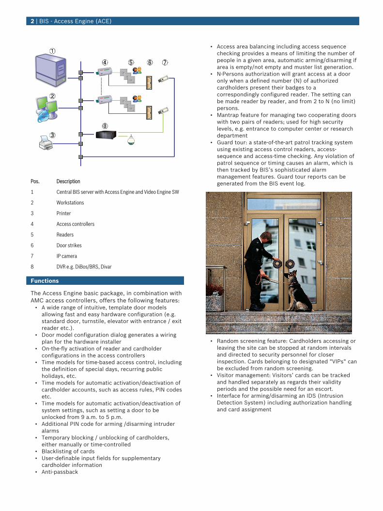
Pos. Description
1 Central BIS server with Access Engine and Video Engine SW
2 Workstations
3 Printer
4 Access controllers
5 Readers
6 Door strikes
7 IP camera
8 DVR e.g. DiBos/BRS, Divar
Functions
The Access Engine basic package, in combination withAMC access controllers, offers the following features:
• A wide range of intuitive, template door modelsallowing fast and easy hardware configuration (e.g.standard door, turnstile, elevator with entrance / exitreader etc.).
• Door model configuration dialog generates a wiringplan for the hardware installer
• On-the-fly activation of reader and cardholderconfigurations in the access controllers
• Time models for time-based access control, includingthe definition of special days, recurring publicholidays, etc.
• Time models for automatic activation/deactivation ofcardholder accounts, such as access rules, PIN codesetc.
• Time models for automatic activation/deactivation ofsystem settings, such as setting a door to beunlocked from 9 a.m. to 5 p.m.
• Additional PIN code for arming /disarming intruderalarms
• Temporary blocking / unblocking of cardholders,either manually or time-controlled
• Blacklisting of cards• User-definable input fields for supplementary
cardholder information• Anti-passback
• Access area balancing including access sequencechecking provides a means of limiting the number ofpeople in a given area, automatic arming/disarming ifarea is empty/not empty and muster list generation.
• N-Persons authorization will grant access at a dooronly when a defined number (N) of authorizedcardholders present their badges to acorrespondingly configured reader. The setting canbe made reader by reader, and from 2 to N (no limit)persons.
• Mantrap feature for managing two cooperating doorswith two pairs of readers; used for high securitylevels, e.g. entrance to computer center or researchdepartment
• Guard tour: a state-of-the-art patrol tracking systemusing existing access control readers, access-sequence and access-time checking. Any violation ofpatrol sequence or timing causes an alarm, which isthen tracked by BIS’s sophisticated alarmmanagement features. Guard tour reports can begenerated from the BIS event log.
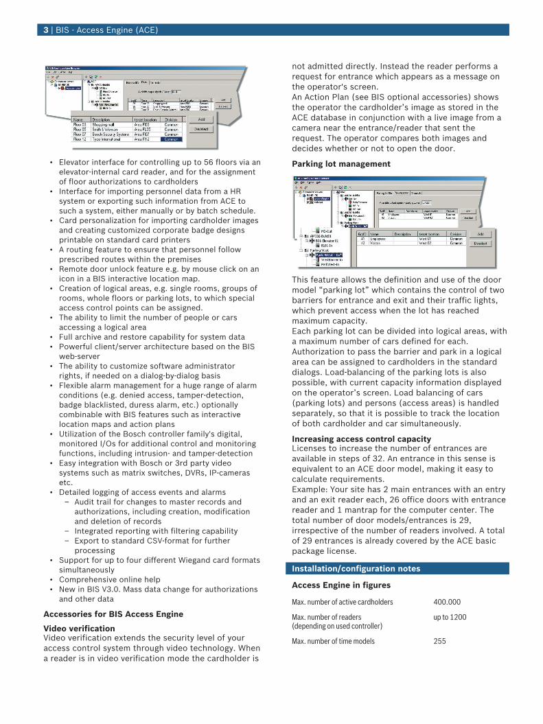
• Random screening feature: Cardholders accessing orleaving the site can be stopped at random intervalsand directed to security personnel for closerinspection. Cards belonging to designated “VIPs“ canbe excluded from random screening.
• Visitor management: Visitors’ cards can be trackedand handled separately as regards their validityperiods and the possible need for an escort.
• Interface for arming/disarming an IDS (IntrusionDetection System) including authorization handlingand card assignment
2 | BIS - Access Engine (ACE)
• Elevator interface for controlling up to 56 floors via anelevator-internal card reader, and for the assignmentof floor authorizations to cardholders
• Interface for importing personnel data from a HRsystem or exporting such information from ACE tosuch a system, either manually or by batch schedule.
• Card personalization for importing cardholder imagesand creating customized corporate badge designsprintable on standard card printers
• A routing feature to ensure that personnel followprescribed routes within the premises
• Remote door unlock feature e.g. by mouse click on anicon in a BIS interactive location map.
• Creation of logical areas, e.g. single rooms, groups ofrooms, whole floors or parking lots, to which specialaccess control points can be assigned.
• The ability to limit the number of people or carsaccessing a logical area
• Full archive and restore capability for system data• Powerful client/server architecture based on the BIS
web-server• The ability to customize software administrator
rights, if needed on a dialog-by-dialog basis• Flexible alarm management for a huge range of alarm
conditions (e.g. denied access, tamper-detection,badge blacklisted, duress alarm, etc.) optionallycombinable with BIS features such as interactivelocation maps and action plans
• Utilization of the Bosch controller family's digital,monitored I/Os for additional control and monitoringfunctions, including intrusion- and tamper-detection
• Easy integration with Bosch or 3rd party videosystems such as matrix switches, DVRs, IP-camerasetc.
• Detailed logging of access events and alarms– Audit trail for changes to master records and
authorizations, including creation, modificationand deletion of records
– Integrated reporting with filtering capability– Export to standard CSV-format for further
processing• Support for up to four different Wiegand card formats
simultaneously• Comprehensive online help• New in BIS V3.0. Mass data change for authorizations
and other data
Accessories for BIS Access Engine
Video verificationVideo verification extends the security level of youraccess control system through video technology. Whena reader is in video verification mode the cardholder is
not admitted directly. Instead the reader performs arequest for entrance which appears as a message onthe operator's screen.An Action Plan (see BIS optional accessories) showsthe operator the cardholder’s image as stored in theACE database in conjunction with a live image from acamera near the entrance/reader that sent therequest. The operator compares both images anddecides whether or not to open the door.
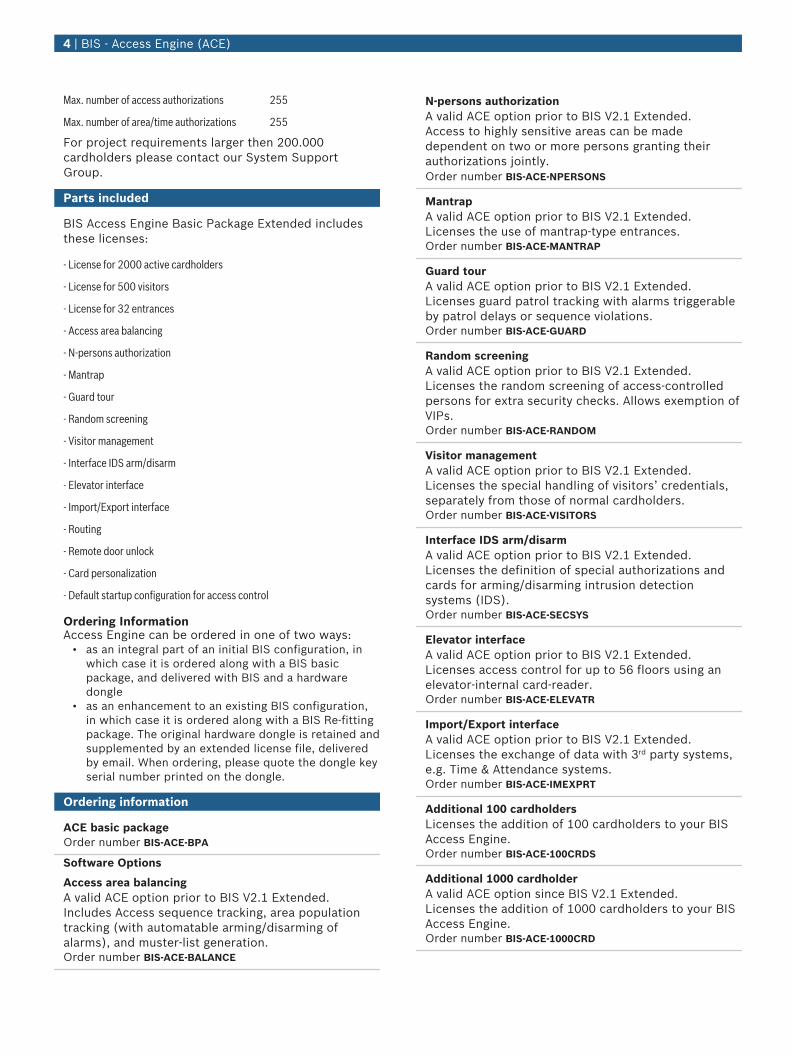
Parking lot management
This feature allows the definition and use of the doormodel “parking lot” which contains the control of twobarriers for entrance and exit and their traffic lights,which prevent access when the lot has reachedmaximum capacity.Each parking lot can be divided into logical areas, witha maximum number of cars defined for each.Authorization to pass the barrier and park in a logicalarea can be assigned to cardholders in the standarddialogs. Load-balancing of the parking lots is alsopossible, with current capacity information displayedon the operator’s screen. Load balancing of cars(parking lots) and persons (access areas) is handledseparately, so that it is possible to track the locationof both cardholder and car simultaneously.
Increasing access control capacityLicenses to increase the number of entrances areavailable in steps of 32. An entrance in this sense isequivalent to an ACE door model, making it easy tocalculate requirements.Example: Your site has 2 main entrances with an entryand an exit reader each, 26 office doors with entrancereader and 1 mantrap for the computer center. Thetotal number of door models/entrances is 29,irrespective of the number of readers involved. A totalof 29 entrances is already covered by the ACE basicpackage license.
Installation/configuration notes
Access Engine in figures
Max. number of active cardholders 400.000
Max. number of readers (depending on used controller)
up to 1200
Max. number of time models 255
3 | BIS - Access Engine (ACE)
Max. number of access authorizations 255
Max. number of area/time authorizations 255
For project requirements larger then 200.000cardholders please contact our System SupportGroup.
Parts included
BIS Access Engine Basic Package Extended includesthese licenses:
- License for 2000 active cardholders
- License for 500 visitors
- License for 32 entrances
- Access area balancing
- N-persons authorization
- Mantrap
- Guard tour
- Random screening
- Visitor management
- Interface IDS arm/disarm
- Elevator interface
- Import/Export interface
- Routing
- Remote door unlock
- Card personalization
- Default startup configuration for access control
Ordering InformationAccess Engine can be ordered in one of two ways:
• as an integral part of an initial BIS configuration, inwhich case it is ordered along with a BIS basicpackage, and delivered with BIS and a hardwaredongle
• as an enhancement to an existing BIS configuration,in which case it is ordered along with a BIS Re-fittingpackage. The original hardware dongle is retained andsupplemented by an extended license file, deliveredby email. When ordering, please quote the dongle keyserial number printed on the dongle.
Ordering information
ACE basic packageOrder number BIS-ACE-BPA
Software Options
Access area balancingA valid ACE option prior to BIS V2.1 Extended.Includes Access sequence tracking, area populationtracking (with automatable arming/disarming ofalarms), and muster-list generation.Order number BIS-ACE-BALANCE
N-persons authorizationA valid ACE option prior to BIS V2.1 Extended.Access to highly sensitive areas can be madedependent on two or more persons granting theirauthorizations jointly.Order number BIS-ACE-NPERSONS
MantrapA valid ACE option prior to BIS V2.1 Extended.Licenses the use of mantrap-type entrances.Order number BIS-ACE-MANTRAP
Guard tourA valid ACE option prior to BIS V2.1 Extended.Licenses guard patrol tracking with alarms triggerableby patrol delays or sequence violations.Order number BIS-ACE-GUARD
Random screeningA valid ACE option prior to BIS V2.1 Extended.Licenses the random screening of access-controlledpersons for extra security checks. Allows exemption ofVIPs.Order number BIS-ACE-RANDOM
Visitor managementA valid ACE option prior to BIS V2.1 Extended.Licenses the special handling of visitors’ credentials,separately from those of normal cardholders.Order number BIS-ACE-VISITORS
Interface IDS arm/disarmA valid ACE option prior to BIS V2.1 Extended.Licenses the definition of special authorizations andcards for arming/disarming intrusion detectionsystems (IDS).Order number BIS-ACE-SECSYS
Elevator interfaceA valid ACE option prior to BIS V2.1 Extended.Licenses access control for up to 56 floors using anelevator-internal card-reader.Order number BIS-ACE-ELEVATR
Import/Export interfaceA valid ACE option prior to BIS V2.1 Extended.Licenses the exchange of data with 3rd party systems,e.g. Time & Attendance systems.Order number BIS-ACE-IMEXPRT
Additional 100 cardholdersLicenses the addition of 100 cardholders to your BISAccess Engine.Order number BIS-ACE-100CRDS
Additional 1000 cardholderA valid ACE option since BIS V2.1 Extended.Licenses the addition of 1000 cardholders to your BISAccess Engine.Order number BIS-ACE-1000CRD
4 | BIS - Access Engine (ACE)

Additional 50 visitorsLicenses the addition of 50 visitor cardholders to yourBIS Access Engine.Order number BIS-ACE-50VIS
Additional 100 visitorsA valid ACE option since BIS V2.1 Extended.Licenses the addition of 100 visitor cardholders toyour BIS Access Engine.Order number BIS-ACE-100VIS
Video verificationLicenses extra verification by video of the identity ofpersons requesting access.Order number BIS-ACE-VIDVERI
Parking lot managementLicenses the use of the parking lot door model withboom-barriers and traffic lights, real-time capacitytracking and load balancing.Order number BIS-ACE-PARKMGR
32-Door-UpgradeLicenses the addition of 32 entrances to your BISAccess Engine.Order number BIS-ACE-32DOORS
RouteA valid ACE option prior to BIS V2.0.Licenses the tracking and enforcement of prescribedroutes through the access-controlled premises.Order number BIS-ACE-ROUTE
Remote door unlockA valid ACE option only prior to BIS V2.0Order number BIS-ACE-REMOPEN
Card personalizationA valid ACE option only prior to BIS V2.0Order number BIS-ACE-IDPRINT
5 | BIS - Access Engine (ACE)
Represented by:
Americas: Europe, Middle East, Africa: Asia-Pacific: China: America Latina:Bosch Security Systems, Inc.130 Perinton ParkwayFairport, New York, 14450, USAPhone: +1 800 289 0096Fax: +1 585 223 [email protected]
Bosch Security Systems B.V.P.O. Box 800025617 BA Eindhoven, The NetherlandsPhone: + 31 40 2577 284Fax: +31 40 2577 [email protected]
Robert Bosch (SEA) Pte Ltd, SecuritySystems11 Bishan Street 21Singapore 573943Phone: +65 6571 2808Fax: +65 6571 [email protected]
Bosch (Shanghai) Security Systems Ltd.201 Building, No. 333 Fuquan RoadNorth IBPChangning District, Shanghai200335 ChinaPhone +86 21 22181111Fax: +86 21 22182398www.boschsecurity.com.cn
Robert Bosch Ltda Security Systems DivisionVia Anhanguera, Km 98CEP 13065-900Campinas, Sao Paulo, BrazilPhone: +55 19 2103 2860Fax: +55 19 2103 [email protected]
© Bosch Security Systems 2012 | Data subject to change without notice8776691851 | en, V6, 12. Dec 2012
Engineered Solutions | AMC2 - Access Modular Controller
AMC2 - Access Modular Controller
www.boschsecurity.com
u Intelligent access manager for one to eightentrances
u Four interfaces include the reader power supply
u Standard 2 GB compact flash
u LCD display for displaying information
u Self-controlling send and receive switching
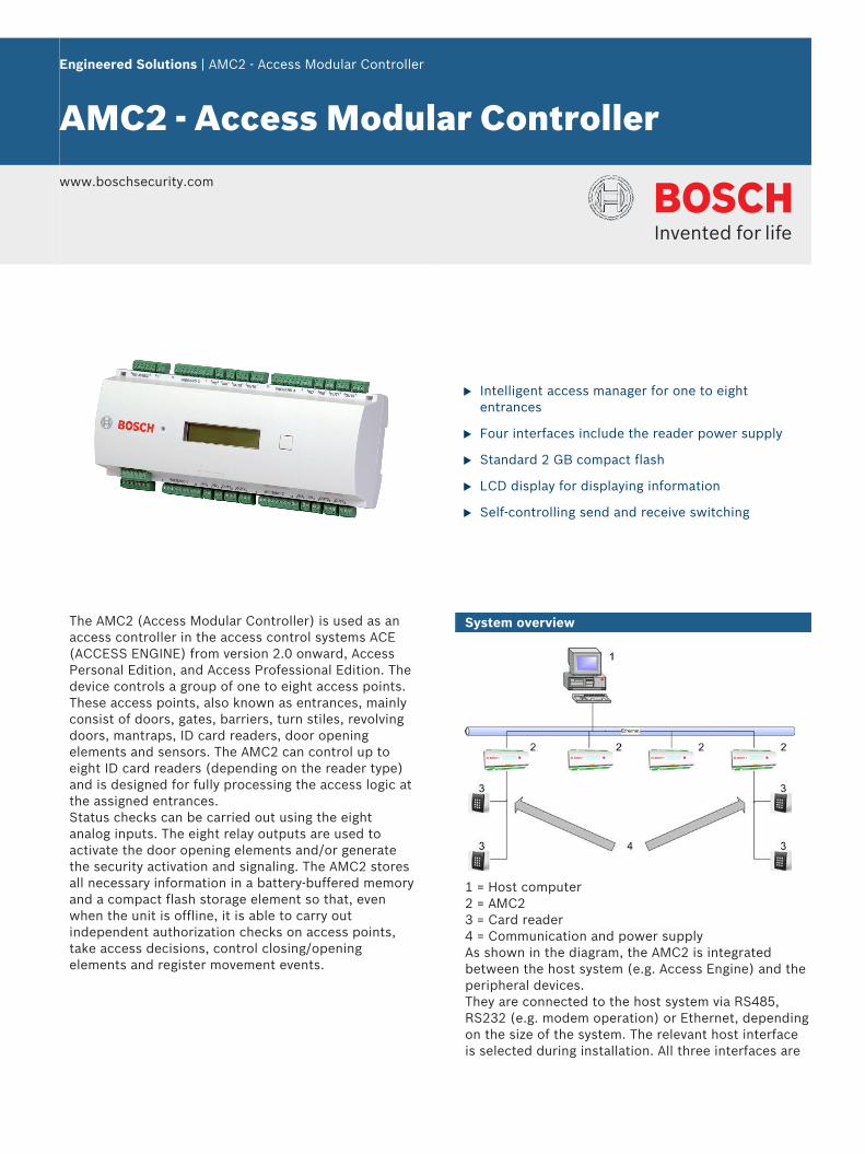
The AMC2 (Access Modular Controller) is used as anaccess controller in the access control systems ACE(ACCESS ENGINE) from version 2.0 onward, AccessPersonal Edition, and Access Professional Edition. Thedevice controls a group of one to eight access points.These access points, also known as entrances, mainlyconsist of doors, gates, barriers, turn stiles, revolvingdoors, mantraps, ID card readers, door openingelements and sensors. The AMC2 can control up toeight ID card readers (depending on the reader type)and is designed for fully processing the access logic atthe assigned entrances.Status checks can be carried out using the eightanalog inputs. The eight relay outputs are used toactivate the door opening elements and/or generatethe security activation and signaling. The AMC2 storesall necessary information in a battery-buffered memoryand a compact flash storage element so that, evenwhen the unit is offline, it is able to carry outindependent authorization checks on access points,take access decisions, control closing/openingelements and register movement events.
System overview
1 = Host computer2 = AMC23 = Card reader4 = Communication and power supplyAs shown in the diagram, the AMC2 is integratedbetween the host system (e.g. Access Engine) and theperipheral devices.They are connected to the host system via RS485,RS232 (e.g. modem operation) or Ethernet, dependingon the size of the system. The relevant host interfaceis selected during installation. All three interfaces are
available on the device by default. With RS485operation, a maximum of eight AMC2’s can beconnected to one party line.There are up to four slots on the peripheral bus forreaders, including the slot for the power supply.
Functions
• Storing downloaded data as listed below:– Master data– Authorizations– Access models– Display texts– Reader configurations
• Interpretation of transaction data from reader– Authorization check– Host request– PIN code
• Control/monitoring– Denial or door release– Switching alarm– Door statuses– Reader operation statuses– Internal alarm statuses
• Messages to Access Engine– Host requests– Transaction data for storing– Error and malfunction messages– Alarm messages
• Power supply for– Readers– Door openers– Contact current feeds
Certifications and approvals
Region Certification
Europe CE EC-Declaration of Conformity
EN50131
2101498_0551-QUA_EMC lEC60950-1 Safety general
EN50131
2101498.0552-QUAIEMC EMC Direc-tive 2004/108/EC
EN50131
EN60950 210440750 lEC 60950-1Safety General
Poland CNBOP 0902 PL_CNBOP 0902
CNBOP 0903 PL_CNBOP 0903
Installation/configuration notes
Power supplyAn external power supply (10 to 30 V DC) for theAMC2 is connected to the first (positive) and third pin(negative).When using an uninterruptible power supply (UPS),the relevant UPS output relay is connected to the pins
• 4 and 7 for alternating current• 5 and 7 for the battery• 6 and 7 for direct current
Otherwise, these pins will short-circuit.
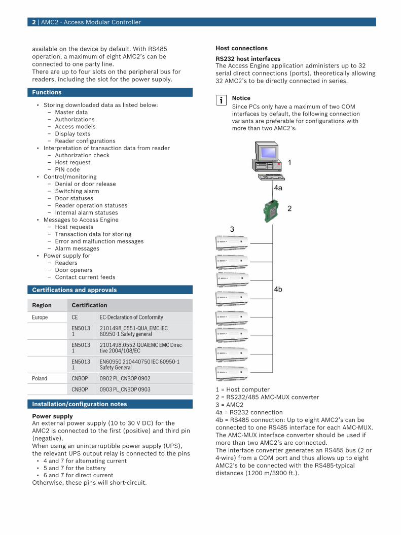
Host connections
RS232 host interfacesThe Access Engine application administers up to 32serial direct connections (ports), theoretically allowing32 AMC2’s to be directly connected in series.
NoticeSince PCs only have a maximum of two COMinterfaces by default, the following connectionvariants are preferable for configurations withmore than two AMC2’s:
1 = Host computer2 = RS232/485 AMC-MUX converter3 = AMC24a = RS232 connection4b = RS485 connection: Up to eight AMC2’s can beconnected to one RS485 interface for each AMC-MUX.The AMC-MUX interface converter should be used ifmore than two AMC2’s are connected.The interface converter generates an RS485 bus (2 or4-wire) from a COM port and thus allows up to eightAMC2’s to be connected with the RS485-typicaldistances (1200 m/3900 ft.).
2 | AMC2 - Access Modular Controller
Alternatively, the RS485 host interface (2 or 4-wire)can be activated in the AMC2 via a jumper. There aretwo sets of connection points; one for the incomingand one for the outgoing bus system.
Quantity restrictions• Please follow the Access Engine installation and
configuration instructions regarding the maximumnumber of access controllers on one access controlsystem and the number of cardholders.
• Max. 4 access points/entrances• Max. 4 ID card readers• Max. 3 peripheral devices via internal RS485 bus• Max. 200,000 cardholders
ID card reader connections
Wiegand interfacesThe AMC2 4W has four connections for connecting upto four ID card readers.ID card reader and door control element interfaces aresplit into four channels, each with four connectionplugs.The following definitions apply to the Wiegandinterface:
• 10-wire interface (incl. shield)• Maximum cable length of 158 m (500 ft.) to ID card
reader• 26-bit Wiegand format• 37-bit Wiegand format
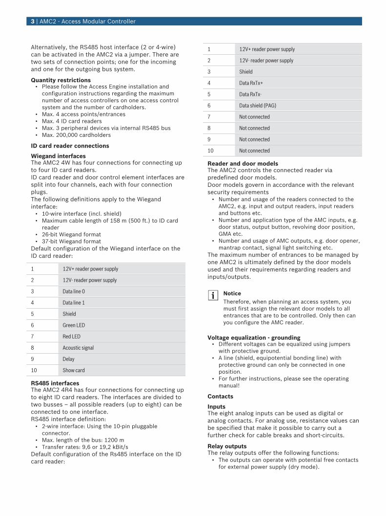
Default configuration of the Wiegand interface on theID card reader:
1 12V+ reader power supply
2 12V- reader power supply
3 Data line 0
4 Data line 1
5 Shield
6 Green LED
7 Red LED
8 Acoustic signal
9 Delay
10 Show card
RS485 interfacesThe AMC2 4R4 has four connections for connecting upto eight ID card readers. The interfaces are divided totwo busses – all possible readers (up to eight) can beconnected to one interface.RS485 interface definition:
• 2-wire interface: Using the 10-pin pluggableconnector.
• Max. length of the bus: 1200 m• Transfer rates: 9,6 or 19,2 kBit/s
Default configuration of the Rs485 interface on the IDcard reader:
1 12V+ reader power supply
2 12V- reader power supply
3 Shield
4 Data RxTx+
5 Data RxTx-
6 Data shield (PAG)
7 Not connected
8 Not connected
9 Not connected
10 Not connected
Reader and door modelsThe AMC2 controls the connected reader viapredefined door models.Door models govern in accordance with the relevantsecurity requirements
• Number and usage of the readers connected to theAMC2, e.g. input and output readers, input readersand buttons etc.
• Number and application type of the AMC inputs, e.g.door status, output button, revolving door position,GMA etc.
• Number and usage of AMC outputs, e.g. door opener,mantrap contact, signal light switching etc.
The maximum number of entrances to be managed byone AMC2 is ultimately defined by the door modelsused and their requirements regarding readers andinputs/outputs.
NoticeTherefore, when planning an access system, youmust first assign the relevant door models to allentrances that are to be controlled. Only then canyou configure the AMC reader.
Voltage equalization - grounding• Different voltages can be equalized using jumpers
with protective ground.• A line (shield, equipotential bonding line) with
protective ground can only be connected in oneposition.
• For further instructions, please see the operatingmanual!
Contacts
InputsThe eight analog inputs can be used as digital oranalog contacts. For analog use, resistance values canbe specified that make it possible to carry out afurther check for cable breaks and short-circuits.
Relay outputsThe relay outputs offer the following functions:
• The outputs can operate with potential free contactsfor external power supply (dry mode).
3 | AMC2 - Access Modular Controller
• The outputs can operate using the internal voltage ofpower supply (wet mode).
• Only ohm resistive loads can be connected to therelay.
• Inductive loads must be bypassed via recoverydiodes. These diodes (1N4004) are enclosed.
General instructions• AMC2 and related equipment should be mounted in a
"secured area".• Detailed connection conditions are specified in the
operating manual!• After purchase, primary AC power must be carried
out by a licensed electrician.
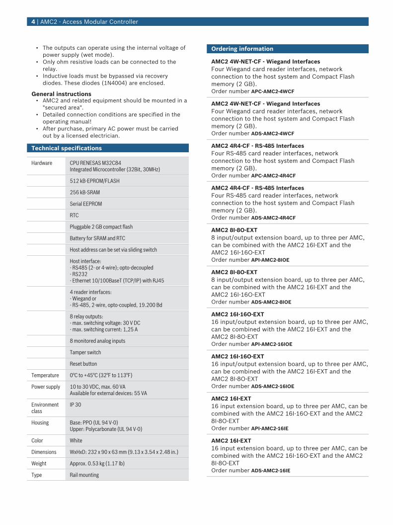
Technical specifications
Hardware CPU RENESAS M32C84Integrated Microcontroller (32Bit, 30MHz)
512 kB-EPROM/FLASH
256 kB-SRAM
Serial EEPROM
RTC
Pluggable 2 GB compact flash
Battery for SRAM and RTC
Host address can be set via sliding switch
Host interface:- RS485 (2- or 4-wire); opto-decoupled- RS232- Ethernet 10/100BaseT (TCP/IP) with RJ45
4 reader interfaces:- Wiegand or- RS-485, 2-wire, opto-coupled, 19.200 Bd
8 relay outputs:- max. switching voltage: 30 V DC- max. switching current: 1,25 A
8 monitored analog inputs
Tamper switch
Reset button
Temperature 0°C to +45°C (32°F to 113°F)
Power supply 10 to 30 VDC, max. 60 VAAvailable for external devices: 55 VA
Environmentclass
IP 30
Housing Base: PPO (UL 94 V-0)Upper: Polycarbonate (UL 94 V-0)
Color White
Dimensions WxHxD: 232 x 90 x 63 mm (9.13 x 3.54 x 2.48 in.)
Weight Approx. 0.53 kg (1.17 lb)
Type Rail mounting
Ordering information
AMC2 4W-NET-CF - Wiegand InterfacesFour Wiegand card reader interfaces, networkconnection to the host system and Compact Flashmemory (2 GB).Order number APC-AMC2-4WCF
AMC2 4W-NET-CF - Wiegand InterfacesFour Wiegand card reader interfaces, networkconnection to the host system and Compact Flashmemory (2 GB).Order number ADS-AMC2-4WCF
AMC2 4R4-CF - RS-485 InterfacesFour RS-485 card reader interfaces, networkconnection to the host system and Compact Flashmemory (2 GB).Order number APC-AMC2-4R4CF
AMC2 4R4-CF - RS-485 InterfacesFour RS-485 card reader interfaces, networkconnection to the host system and Compact Flashmemory (2 GB).Order number ADS-AMC2-4R4CF
AMC2 8I-8O-EXT8 input/output extension board, up to three per AMC,can be combined with the AMC2 16I-EXT and theAMC2 16I-16O-EXTOrder number API-AMC2-8IOE
AMC2 8I-8O-EXT8 input/output extension board, up to three per AMC,can be combined with the AMC2 16I-EXT and theAMC2 16I-16O-EXTOrder number ADS-AMC2-8IOE
AMC2 16I-16O-EXT16 input/output extension board, up to three per AMC,can be combined with the AMC2 16I-EXT and theAMC2 8I-8O-EXTOrder number API-AMC2-16IOE
AMC2 16I-16O-EXT16 input/output extension board, up to three per AMC,can be combined with the AMC2 16I-EXT and theAMC2 8I-8O-EXTOrder number ADS-AMC2-16IOE
AMC2 16I-EXT16 input extension board, up to three per AMC, can becombined with the AMC2 16I-16O-EXT and the AMC28I-8O-EXTOrder number API-AMC2-16IE
AMC2 16I-EXT16 input extension board, up to three per AMC, can becombined with the AMC2 16I-16O-EXT and the AMC28I-8O-EXTOrder number ADS-AMC2-16IE
4 | AMC2 - Access Modular Controller
AMC2-16IONStandalone Controller with inputs and outputs, only.Order number API-AMC2-16ION
AMC2-16IONController with inputs and outputs, only.Order number ADS-AMC2-16ION
Accessories
AMC2 4W-EXT - Wiegand Extension BoardThe extension module AMC2 4W-EXT is equipped withfour Wiegand type reader-interfaces plus eight inputsand eight outputs. Hence with the AMC2 4W-EXT it ispossible to double the number of readers on an AMC24W from 4 to 8.Order number API-AMC2-4WE
AMC2 4W-EXT - Wiegand Extension BoardThe extension module AMC2 4W-EXT is equipped withfour Wiegand type reader-interfaces plus eight inputsand eight outputs. Hence with the AMC2 4W-EXT it ispossible to double the number of readers on an AMC24W from 4 to 8.Order number ADS-AMC2-4WE
AMC2 ENC-EMEA - EnclosureThis enclosure is used for securely mounting andhousing the AMC2 and a power supply (e.g. AMCPBC60).Order number AEC-AMC2-EMEA01
AMC2 ENC-UL1 - Enclosure - SmallAMC2 enclosure with single din rail.Order number AEC-AMC2-UL1
AMC2 ENC-UL2 - Enclosure - LargeAMC2 enclosure with two din rails.Order number AEC-AMC2-UL2
AEC-PANEL19-4DR - Mounting plate with four DIN railsMounting plate with four DIN rails for 19” racks toconnect max. four AMC2 devices.Order number AEC-PANEL19-4DR
AEC-PANEL19-UPS - Mounting plate with two DIN railsMounting plate with two DIN rails, a battery bracket,and screw sockets for the power supply to mount into19” racks.Order number AEC-PANEL19-UPS
PBC-60 - power supply and battery chargerA power supply unit with an integrated batterycharging device.Order number APS-PBC-60
Gel Battery 12 V / 7.2 Ah(DU = 1 unit)Order number IPP-12V-7.2Ah
AMC RAIL-250 mounting railMounting rail (250 mm) for mounting the accesscontroller AMC-4W without the metal housing AMCENC-V1.Order number ACX-RAIL-250
AMC RAIL-400 mounting railMounting rail (400 mm) for mounting the AMC-4W,AMC PS-12V-60W and AMC UPS-12V when the metalhousing AMC ENC-V1 is not used.Order number ACX-RAIL-400
AMC-MUX interface converterInterface converter – RS-232 into RS-485/422Order number ACX-AMC-MUX
AMC-MUX-EXT interface extensionAn extension module for the AMC-MUX to create anetwork star topology.Order number ACX-AMC-MUXE
5 | AMC2 - Access Modular Controller
Systems | PBC-60 - power supply and battery charger
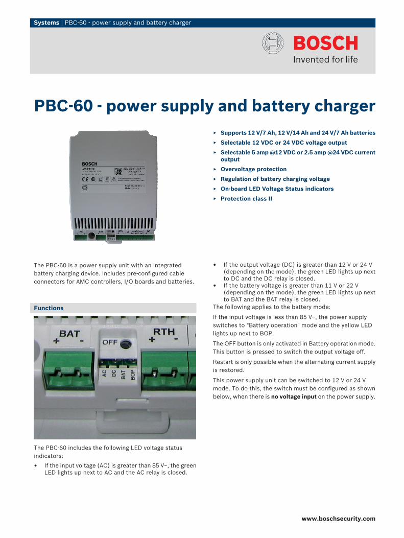
The PBC-60 is a power supply unit with an integratedbattery charging device. Includes pre-configured cableconnectors for AMC controllers, I/O boards and batteries.
Functions
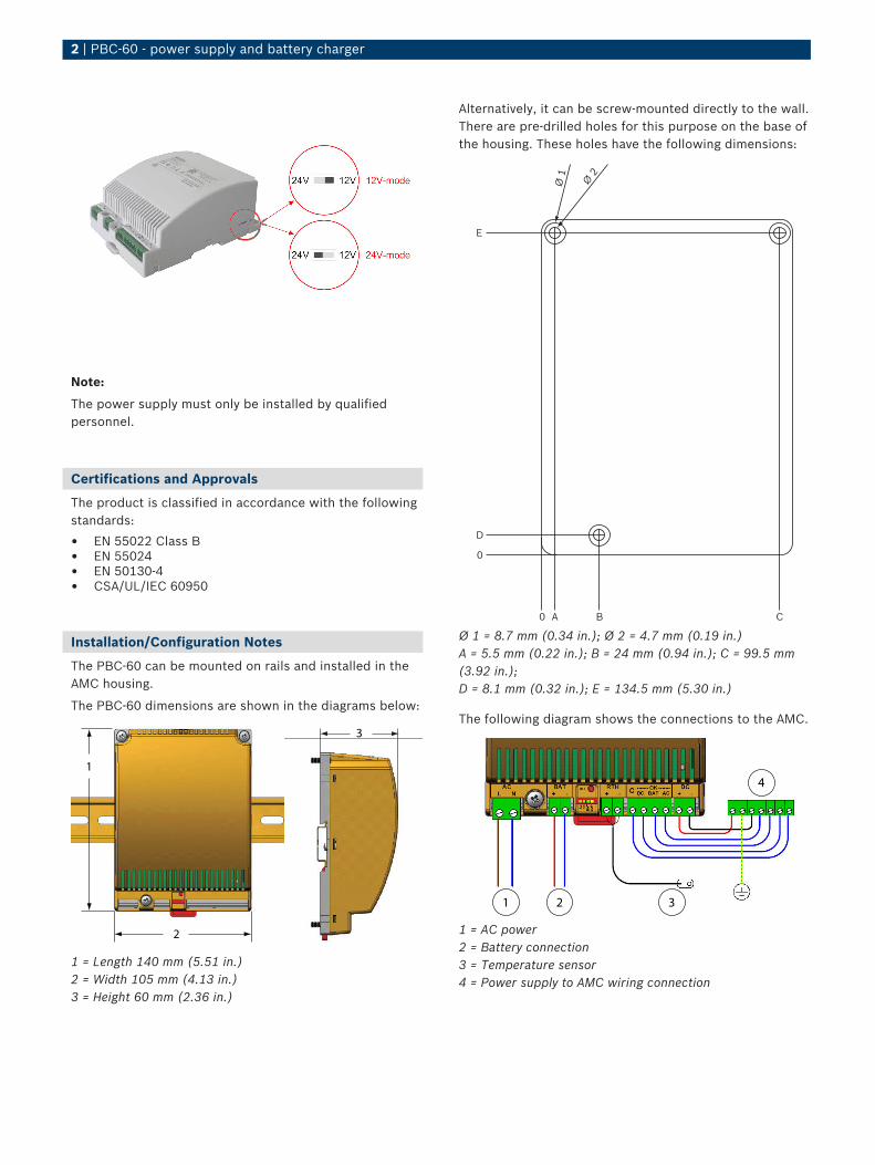
The PBC-60 includes the following LED voltage statusindicators:
• If the input voltage (AC) is greater than 85 V~, the greenLED lights up next to AC and the AC relay is closed.
• If the output voltage (DC) is greater than 12 V or 24 V(depending on the mode), the green LED lights up nextto DC and the DC relay is closed.
• If the battery voltage is greater than 11 V or 22 V(depending on the mode), the green LED lights up nextto BAT and the BAT relay is closed.
The following applies to the battery mode:
If the input voltage is less than 85 V~, the power supplyswitches to "Battery operation" mode and the yellow LEDlights up next to BOP.
The OFF button is only activated in Battery operation mode.This button is pressed to switch the output voltage off.
Restart is only possible when the alternating current supplyis restored.
This power supply unit can be switched to 12 V or 24 Vmode. To do this, the switch must be configured as shownbelow, when there is no voltage input on the power supply.
PBC-60 - power supply and battery charger▶ Supports 12 V/7 Ah, 12 V/14 Ah and 24 V/7 Ah batteries
▶ Selectable 12 VDC or 24 VDC voltage output
▶ Selectable 5 amp @12 VDC or 2.5 amp @24 VDC currentoutput
▶ Overvoltage protection
▶ Regulation of battery charging voltage
▶ On-board LED Voltage Status indicators
▶ Protection class II
www.boschsecurity.com
2 | PBC-60 - power supply and battery charger
Note:
The power supply must only be installed by qualifiedpersonnel.
Certifications and Approvals
The product is classified in accordance with the followingstandards:
• EN 55022 Class B• EN 55024• EN 50130-4• CSA/UL/IEC 60950
Installation/Configuration Notes
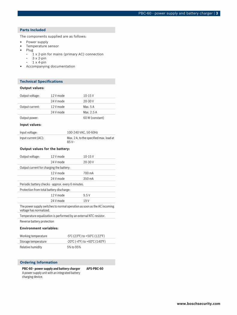
The PBC-60 can be mounted on rails and installed in theAMC housing.
The PBC-60 dimensions are shown in the diagrams below:
1
2
3
1 = Length 140 mm (5.51 in.)2 = Width 105 mm (4.13 in.)3 = Height 60 mm (2.36 in.)
Alternatively, it can be screw-mounted directly to the wall.There are pre-drilled holes for this purpose on the base ofthe housing. These holes have the following dimensions:
0
0
Ø 1
Ø 2
A B C
D
E
Ø 1 = 8.7 mm (0.34 in.); Ø 2 = 4.7 mm (0.19 in.)A = 5.5 mm (0.22 in.); B = 24 mm (0.94 in.); C = 99.5 mm(3.92 in.);D = 8.1 mm (0.32 in.); E = 134.5 mm (5.30 in.)
The following diagram shows the connections to the AMC.
1 2 3
4
1 = AC power2 = Battery connection3 = Temperature sensor4 = Power supply to AMC wiring connection
PBC-60 - power supply and battery charger | 3
Parts Included
The components supplied are as follows:
• Power supply• Temperature sensor• Plug
- 1 x 2-pin for mains (primary AC) connection- 3 x 2-pin- 1 x 4-pin
• Accompanying documentation
Technical Specifications
Output values:
Output voltage: 12 V mode 10-15 V
24 V mode 20-30 V
Output current: 12 V mode Max. 5 A
24 V mode Max. 2.5 A
Output power: 60 W (constant)
Input values:
Input voltage: 100-240 VAC, 50-60Hz
Input current (AC): Max. 2 A, to the specified max. load at85 V~
Output values for the battery:
Output voltage: 12 V mode 10-15 V
24 V mode 20-30 V
Output current for charging the battery:
12 V mode 700 mA
24 V mode 350 mA
Periodic battery checks - approx. every 6 minutes.
Protection from total battery discharge:
12 V mode 9.5 V
24 V mode 19 V
The power supply switches to normal operation as soon as the AC incomingvoltage has normalized.
Temperature equalization is performed by an external NTC resistor.
Reverse battery protection
Environment variables:
Working temperature -5°C (23°F) to +50°C (122°F)
Storage temperature -20°C (-4°F) to +60°C (140°F)
Relative humidity 5% to 95%
Ordering Information
PBC-60 - power supply and battery chargerA power supply unit with an integrated batterycharging device.
APS-PBC-60
www.boschsecurity.com
Systems | AMC2 - Input/Output Extension Boards
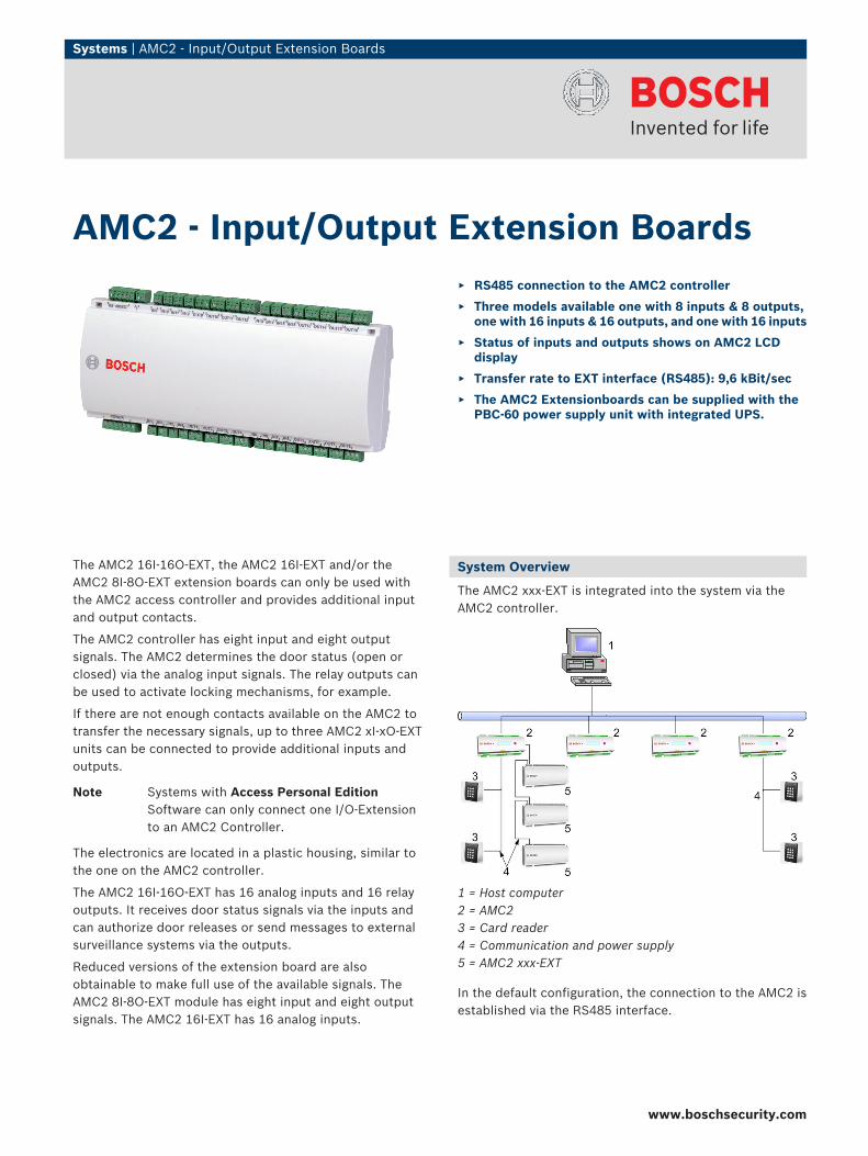
The AMC2 16I-16O-EXT, the AMC2 16I-EXT and/or theAMC2 8I‑8O-EXT extension boards can only be used withthe AMC2 access controller and provides additional inputand output contacts.
The AMC2 controller has eight input and eight outputsignals. The AMC2 determines the door status (open orclosed) via the analog input signals. The relay outputs canbe used to activate locking mechanisms, for example.
If there are not enough contacts available on the AMC2 totransfer the necessary signals, up to three AMC2 xI-xO-EXTunits can be connected to provide additional inputs andoutputs.
Note Systems with Access Personal EditionSoftware can only connect one I/O-Extensionto an AMC2 Controller.
The electronics are located in a plastic housing, similar tothe one on the AMC2 controller.
The AMC2 16I-16O-EXT has 16 analog inputs and 16 relayoutputs. It receives door status signals via the inputs andcan authorize door releases or send messages to externalsurveillance systems via the outputs.
Reduced versions of the extension board are alsoobtainable to make full use of the available signals. TheAMC2 8I-8O-EXT module has eight input and eight outputsignals. The AMC2 16I-EXT has 16 analog inputs.
System Overview
The AMC2 xxx-EXT is integrated into the system via theAMC2 controller.
1 = Host computer2 = AMC23 = Card reader4 = Communication and power supply5 = AMC2 xxx-EXT
In the default configuration, the connection to the AMC2 isestablished via the RS485 interface.
AMC2 - Input/Output Extension Boards▶ RS485 connection to the AMC2 controller
▶ Three models available one with 8 inputs & 8 outputs,one with 16 inputs & 16 outputs, and one with 16 inputs
▶ Status of inputs and outputs shows on AMC2 LCDdisplay
▶ Transfer rate to EXT interface (RS485): 9,6 kBit/sec
▶ The AMC2 Extensionboards can be supplied with thePBC-60 power supply unit with integrated UPS.
www.boschsecurity.com
2 | AMC2 - Input/Output Extension Boards
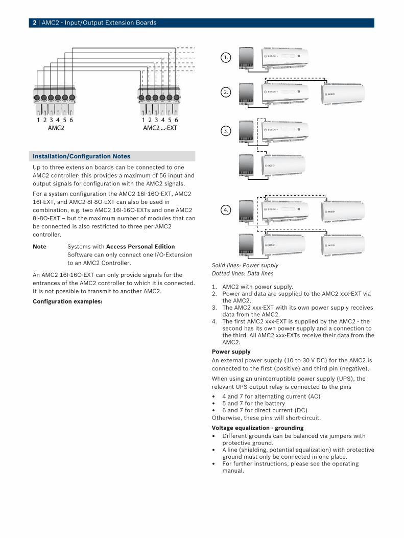
Installation/Configuration Notes
Up to three extension boards can be connected to oneAMC2 controller; this provides a maximum of 56 input andoutput signals for configuration with the AMC2 signals.
For a system configuration the AMC2 16I-16O-EXT, AMC216I-EXT, and AMC2 8I-8O-EXT can also be used incombination, e.g. two AMC2 16I-16O-EXTs and one AMC28I-8O-EXT – but the maximum number of modules that canbe connected is also restricted to three per AMC2controller.
Note Systems with Access Personal EditionSoftware can only connect one I/O-Extensionto an AMC2 Controller.
An AMC2 16I-16O-EXT can only provide signals for theentrances of the AMC2 controller to which it is connected.It is not possible to transmit to another AMC2.
Configuration examples:
Solid lines: Power supplyDotted lines: Data lines
1. AMC2 with power supply.2. Power and data are supplied to the AMC2 xxx-EXT via
the AMC2.3. The AMC2 xxx-EXT with its own power supply receives
data from the AMC2.4. The first AMC2 xxx-EXT is supplied by the AMC2 - the
second has its own power supply and a connection tothe third. All AMC2 xxx-EXTs receive their data from theAMC2.
Power supplyAn external power supply (10 to 30 V DC) for the AMC2 isconnected to the first (positive) and third pin (negative).
When using an uninterruptible power supply (UPS), therelevant UPS output relay is connected to the pins
• 4 and 7 for alternating current (AC)• 5 and 7 for the battery• 6 and 7 for direct current (DC)Otherwise, these pins will short-circuit.
Voltage equalization - grounding• Different grounds can be balanced via jumpers with
protective ground.• A line (shielding, potential equalization) with protective
ground must only be connected in one place.• For further instructions, please see the operating
manual.

AMC2 - Input/Output Extension Boards | 3
Contacts
InputsThe analog inputs can be used as digital or analog contacts.For analog use, resistance values can be specified to checkfor cable breaks and short-circuits.
Relay outputsThe relay outputs offer the following functions:
• The outputs can operate with potential free contacts forexternal power supply (dry mode).
• The outputs can operate using the internal voltage ofpower supply (wet mode).
• Only ohm resistive loads can be connected to the relay.• Inductive loads must be bypassed via recovery diodes.
These diodes (IN4004) are enclosed.
General instructions• All access equipment should be mounted within a
"secured area".• Detailed connection conditions are specified in the
operating manual!• After purchase, primary AC power must be carried out
by a licensed electrician.
Technical Specifications
Hardware 16 or 8 or null relay outputs - with ohm load:- max. switching voltage: 30 V DC- max. switching current: 1,25 A
16 or 8 analog inputs
Tamper switch
Temperature 0°C to +45°C (32° F to 113° F)
Power supply - 10 or 30 V DC, max. 60 VAAvailable for external devices: 55 VA- or via the AMC2
Protectionclass
IP 30
Housing Base: PPO (UL 94 V-0)Upper: Polycarbonate (UL 94 V-0)
Color White
Dimensions WxHxD: 232 x 90 x 46 mm (9.13 x 3.54 x 1.81 in.)
Weight Approx. 0.4 kg (0.88 lb)
Type Rail mounting
Ordering Information
AMC2 8I-8O-EXT8 input/output extension board, up to three perAMC, can be combined with the AMC2 16I-EXTand the AMC2 16I-16O-EXT
API-AMC2-8IOE
AMC2 16I-16O-EXT16 input/output extension board, up to threeper AMC, can be combined with the AMC2 16I-EXT and the AMC2 8I-8O-EXT
API-AMC2-16IOE
AMC2 16I-EXT16 input extension board, up to three per AMC,can be combined with the AMC2 16I-16O-EXTand the AMC2 8I-8O-EXT
API-AMC2-16IE
www.boschsecurity.com

Intrusion Alarm Systems | D126 Standby Battery (12 V, 7 Ah)
D126 Standby Battery (12 V, 7 Ah)
www.boschsecurity.com
u 12 VDC sealed lead-acid
u Fully rechargeable
u Maintenance‑free
u For use as secondary power for accessory modules
u Long service life
A maintenance‑free, sealed lead‑acid, standby andauxiliary power supply that provides long service lifeand dependability.The battery is for use only with charging circuitscalibrated for lead‑acid batteries. It is suitable forsupplying backup power for fire, security, and accesscontrol systems during AC power failures.The D126 fits in any of the currently offeredenclosures and connects to the two color‑codedbattery leads supplied with the control panel ormodule. Use a D122 Dual Battery Harness to connecttwo D126 batteries in parallel and double the amphour output.
Certifications and approvals
NYC/BSA 582-85-SA
DSI CDFM
Region Certification
Europe CE Council Directive 89/336/EEC Electro-magnetic Compatibility
USA UL ALVY: Access Control Systems Units(UL294), APOU: Proprietary Alarm Units(UL1076), UEHX7: Signaling Applian-ces, Miscellaneous Certified for Canada(cUL)
Region Certification
FM
CSFM 7167-1615: 0100 CONTROL UNIT(HOUSEHOLD)
CSFM 7165-1615: 0113 FIRE ALARM CON-TROL UNIT (COMMERCIAL)
CSFM 7167-1615:0124 7167 -- CONTROLUNIT (HOUSEHOLD)
CSFM 7165-1615:0119 7165 -- FIRE ALARMCONTROL UNIT (COMMERCIAL)
CSFM 7167-1615:0239 7167 -- CONTROLUNIT (HOUSEHOLD)
Installation/configuration notes
Standby Power RequirementsRefer to the appropriate control panel installationmanual for information on calculating the standbybattery requirements for the system. Total continuousand intermittent current requirements must notexceed the amp hour capacity of the battery.
Technical specifications
Capacity: 12 V, 7 Ah
Compatible Panels: Compatible with all control panels
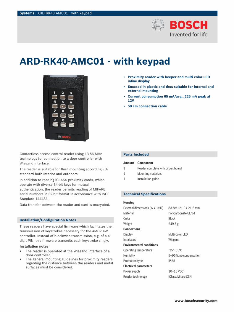
Systems | ARD-RK40-AMC01 - with keypad
Contactless access control reader using 13.56 MHztechnology for connection to a door controller withWiegand interface.
The reader is suitable for flush-mounting according EU-standard both interior and outdoors.
In addition to reading iCLASS proximity cards, whichoperate with diverse 64-bit keys for mutualauthentication, the reader permits reading of MIFAREserial numbers in 32-bit format in accordance with ISOStandard 14443A.
Data transfer between the reader and card is encrypted.
Installation/Configuration Notes
These readers have special firmware which facilitates thetransmission of keystrokes necessary for the AMC2 4Wcontroller. Instead of blockwise transmission, e.g. of a 4-digit PIN, this firmware transmits each keystroke singly.
Installation notes• The reader is operated at the Wiegand interface of a
door controller.• The general mounting guidelines for proximity readers
regarding the distance between the readers and metalsurfaces must be considered.
Parts Included
Amount Component
1 Reader complete with circuit board
1 Mounting materials
1 Installation guide
Technical Specifications
Housing
External dimensions (W x H x D) 83.8 x 121.9 x 21.6 mm
Material Polycarbonate UL 94
Color Black
Weight 249.5 g
Connections
Display Multi-color LED
Interfaces Wiegand
Environmental conditions
Operating temperature -35°–65°C
Humidity 5–95%, no condensation
Protection type IP 55
Electrical parameters
Power supply 10–16 VDC
Reader technology IClass, Mifare CSN
ARD-RK40-AMC01 - with keypad▶ Proximity reader with beeper and multi-color LED
inline display
▶ Encased in plastic and thus suitable for internal andexternal mounting
▶ Current consumption 65 mA/avg., 225 mA peak at12V
▶ 50 cm connection cable
www.boschsecurity.com
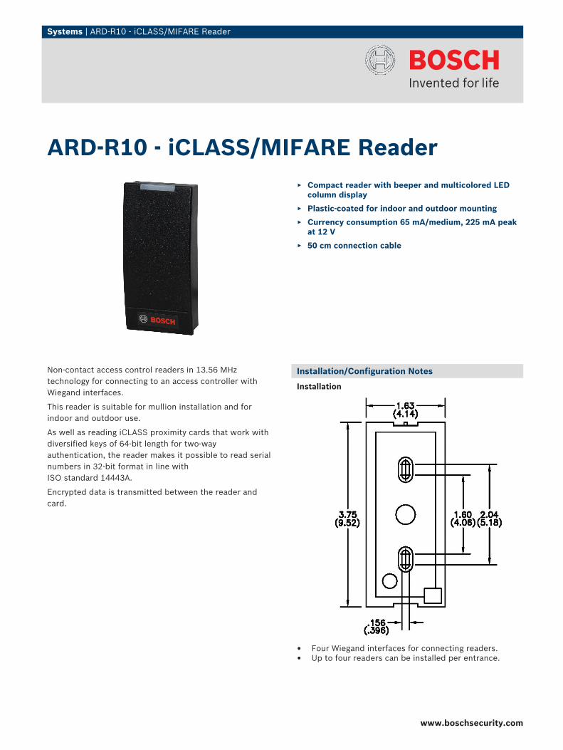
Systems | ARD-R10 - iCLASS/MIFARE Reader
Non-contact access control readers in 13.56 MHztechnology for connecting to an access controller withWiegand interfaces.
This reader is suitable for mullion installation and forindoor and outdoor use.
As well as reading iCLASS proximity cards that work withdiversified keys of 64-bit length for two-wayauthentication, the reader makes it possible to read serialnumbers in 32-bit format in line withISO standard 14443A.
Encrypted data is transmitted between the reader andcard.
Installation/Configuration Notes
Installation
• Four Wiegand interfaces for connecting readers.• Up to four readers can be installed per entrance.
ARD-R10 - iCLASS/MIFARE Reader▶ Compact reader with beeper and multicolored LED
column display
▶ Plastic-coated for indoor and outdoor mounting
▶ Currency consumption 65 mA/medium, 225 mA peakat 12 V
▶ 50 cm connection cable
www.boschsecurity.com
2 | ARD-R10 - iCLASS/MIFARE Reader
Please follow the general mounting instructions for theproximity reader regarding the distance between readersand metallic surfaces.
Parts Included
Quantity Component
1 Reader body with board
1 Mounting material
1 Installation guide
Technical Specifications
Housing
External dimensions (W x H x D) 102.6 x 48.3 x 20.3 mm
Material Polycarbonate (UL 94)
Color Black
Weight 90.7 g
Connections
Display Multicolored LED
Interfaces Wiegand
Environmental conditions
Operating temperature -35° to 65°C
Humidity 5 to 95% no condensation water
Environment class IP 55
Electrical parameters
Power supply 10 to 16 VDC
Reading process IClass, MIFARE CSN
Operating/modulation frequency 13.56 MHz
Reading distance 5 cm to 7.6 cm with iCLASS card2.5 cm with iCLASS TAG or key fob
Ordering Information
ARD-R10 - iCLASS/MIFARE ReaderNon-contact compact reader with beeper andmulticolored LED display for Wiegand interfa-ces.
ARD-R10EMEA-000
Accessories
ARD-R10-AP-G Surface-Mount PanelSurface-mount panel for ARD-R10 reader.10 items/packaging unit.
F01U508789
Americas:Bosch Security Systems, Inc.130 Perinton ParkwayFairport, New York, 14450, USAPhone: +1 800 289 0096Fax: +1 585 223 [email protected]
Europe, Middle East, Africa:Bosch Security Systems B.V.P.O. Box 800025600 JB Eindhoven, The NetherlandsPhone: + 31 40 2577 284Fax: +31 40 2577 [email protected]
Asia-Pacific:Robert Bosch (SEA) Pte Ltd, Security Systems11 Bishan Street 21Singapore 573943Phone: +65 6258 5511Fax: +65 6571 [email protected]
Represented by
© Bosch Security Systems Inc. 2010 | Data subject to change without noticeT1922937099 | Cur: en-US, V16, 2 Dec 2010
Systems | ARD-R90 - iCLASS Reader - APR/EMEA
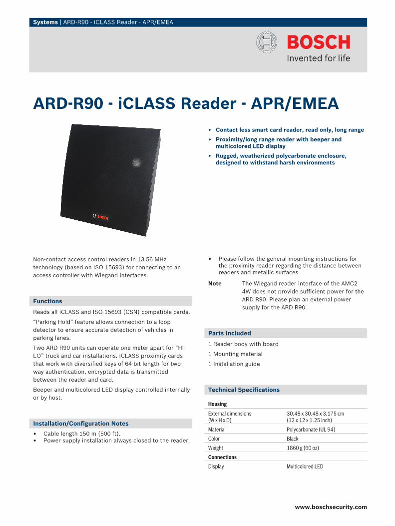
Non-contact access control readers in 13.56 MHztechnology (based on ISO 15693) for connecting to anaccess controller with Wiegand interfaces.
Functions
Reads all iCLASS and ISO 15693 (CSN) compatible cards.
“Parking Hold” feature allows connection to a loopdetector to ensure accurate detection of vehicles inparking lanes.
Two ARD R90 units can operate one meter apart for “HI-LO” truck and car installations. iCLASS proximity cardsthat work with diversified keys of 64-bit length for two-way authentication, encrypted data is transmittedbetween the reader and card.
Beeper and multicolored LED display controlled internallyor by host.
Installation/Configuration Notes
• Cable length 150 m (500 ft).• Power supply installation always closed to the reader.
• Please follow the general mounting instructions forthe proximity reader regarding the distance betweenreaders and metallic surfaces.
Note The Wiegand reader interface of the AMC24W does not provide sufficient power for theARD R90. Please plan an external powersupply for the ARD R90.
Parts Included
1 Reader body with board
1 Mounting material
1 Installation guide
Technical Specifications
Housing
External dimensions (W x H x D)
30,48 x 30,48 x 3,175 cm(12 x 12 x 1.25 inch)
Material Polycarbonate (UL 94)
Color Black
Weight 1860 g (60 oz)
Connections
Display Multicolored LED
ARD-R90 - iCLASS Reader - APR/EMEA▶ Contact less smart card reader, read only, long range
▶ Proximity/long range reader with beeper andmulticolored LED display
▶ Rugged, weatherized polycarbonate enclosure,designed to withstand harsh environments
www.boschsecurity.com
2 | ARD-R90 - iCLASS Reader - APR/EMEA
Housing
Interfaces Wiegand
Environment conditions
Operating temperature -35° to 65°C (-31° to 150°F)
Humidity 5 to 95% no condensation water
Environment class IP55
Electrical parameters
Power supply 12 – 24 VDC reserve voltage pro-tected (linear supply recommended)
Current consumption (Avg/Peak)
480/1800 mA (12 VDC)230/900 mA (24 VDC)
Reading process iCLASS
Operating/modulation frequency 13.56 MHz
Reading distance 45 cm (17.72 in) with iCLASS card22,9 cm (9.01 in) with iCLASS key/tag
Cable distance 150 m (500 ft)
Recommended cable ALPHA 1295 (22 AWG)
Ordering Information
ARD-R90 - iCLASS Reader - APR/EMEAProximity long range access control readerwith Wiegand interface.
ARD-R90-AKT00
Americas:Bosch Security Systems, Inc.130 Perinton ParkwayFairport, New York, 14450, USAPhone: +1 800 289 0096Fax: +1 585 223 [email protected]
Europe, Middle East, Africa:Bosch Security Systems B.V.P.O. Box 800025600 JB Eindhoven, The NetherlandsPhone: + 31 40 2577 284Fax: +31 40 2577 [email protected]
Asia-Pacific:Robert Bosch (SEA) Pte Ltd, Security Systems11 Bishan Street 21Singapore 573943Phone: +65 6258 5511Fax: +65 6571 [email protected]
Represented by
© Bosch Security Systems Inc. 2010 | Data subject to change without noticeT4398697227 | Cur: en-US, V13, 2 Dec 2010
Engineered Solutions | ARD-FPBEPxx-OC - BioEntry Plus with card reader / Americas
ARD-FPBEPxx-OC - BioEntry Plus with cardreader / Americas
www.boschsecurity.com
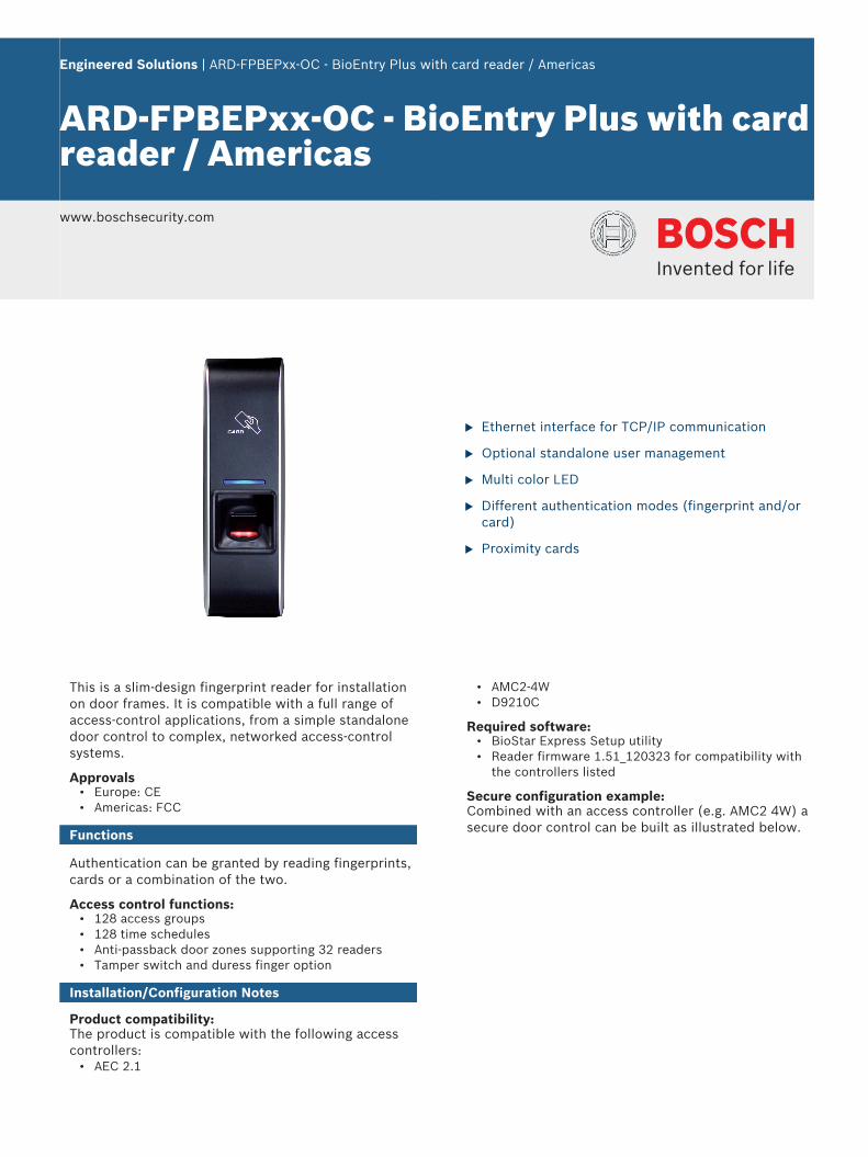
u Ethernet interface for TCP/IP communication
u Optional standalone user management
u Multi color LED
u Different authentication modes (fingerprint and/orcard)
u Proximity cards
This is a slim-design fingerprint reader for installationon door frames. It is compatible with a full range ofaccess-control applications, from a simple standalonedoor control to complex, networked access-controlsystems.
Approvals• Europe: CE• Americas: FCC
Functions
Authentication can be granted by reading fingerprints,cards or a combination of the two.
Access control functions:• 128 access groups• 128 time schedules• Anti-passback door zones supporting 32 readers• Tamper switch and duress finger option
Installation/Configuration Notes
Product compatibility:The product is compatible with the following accesscontrollers:
• AEC 2.1
• AMC2-4W• D9210C
Required software:• BioStar Express Setup utility• Reader firmware 1.51_120323 for compatibility with
the controllers listed
Secure configuration example:Combined with an access controller (e.g. AMC2 4W) asecure door control can be built as illustrated below.
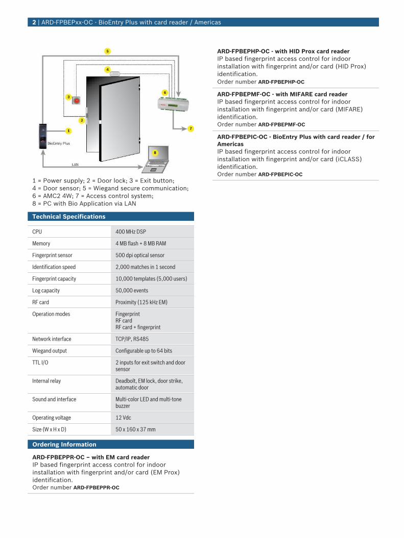
1 = Power supply; 2 = Door lock; 3 = Exit button;4 = Door sensor; 5 = Wiegand secure communication;6 = AMC2 4W; 7 = Access control system;8 = PC with Bio Application via LAN
Technical Specifications
CPU 400 MHz DSP
Memory 4 MB flash + 8 MB RAM
Fingerprint sensor 500 dpi optical sensor
Identification speed 2,000 matches in 1 second
Fingerprint capacity 10,000 templates (5,000 users)
Log capacity 50,000 events
RF card Proximity (125 kHz EM)
Operation modes FingerprintRF cardRF card + fingerprint
Network interface TCP/IP, RS485
Wiegand output Configurable up to 64 bits
TTL I/O 2 inputs for exit switch and doorsensor
Internal relay Deadbolt, EM lock, door strike,automatic door
Sound and interface Multi-color LED and multi-tonebuzzer
Operating voltage 12 Vdc
Size (W x H x D) 50 x 160 x 37 mm
Ordering Information
ARD-FPBEPPR-OC – with EM card readerIP based fingerprint access control for indoorinstallation with fingerprint and/or card (EM Prox)identification.Order number ARD-FPBEPPR-OC
ARD-FPBEPHP-OC - with HID Prox card readerIP based fingerprint access control for indoorinstallation with fingerprint and/or card (HID Prox)identification.Order number ARD-FPBEPHP-OC
ARD-FPBEPMF-OC - with MIFARE card readerIP based fingerprint access control for indoorinstallation with fingerprint and/or card (MIFARE)identification.Order number ARD-FPBEPMF-OC
ARD-FPBEPIC-OC - BioEntry Plus with card reader / forAmericasIP based fingerprint access control for indoorinstallation with fingerprint and/or card (iCLASS)identification.Order number ARD-FPBEPIC-OC
2 | ARD-FPBEPxx-OC - BioEntry Plus with card reader / Americas

Systems | Contactless iClass Cards
Contactless card with iClass Chip.
Functions
• ACD-ICLASS cards have an embedded wire antennaand iClass chip embedded.
• The card is recognized and read when held in front ofthe reader.
• The reading process is passive with a frequency of13.56 MHz
• ICLASS cards support multiple application areas thatcan be individually protected.
• All credentials have a unique chip number and acustomer (or facility) code.
Installation/Configuration Notes
Contactless credentials with iClass chip are ideal forinstallations with high-availability systems and wherecredentials may be exposed to abnormal conditions
Reading ranges reach up to 12.5 cm depending on thereaders used.
Technical Specifications
ACD-ICLASS card
Dimensions 85.7 x 54 x 0.76 mm
Coding Chip number, customer (or facility)code
Transmission frequency 13.56 MHz
Data preservation 10 years
Transaction times < 100 ms
Ordering Information
ACD-ICLASS-256-2AR 50/eachICLASS ID card with 256 byte data storage, 2application areas, one of which can be cus-tomized. Packing information: 50 cards/each unit
ACD-ICL256-2AR
ACD-ICLASS-2AR 50/eachICLASS ID card with 2 Kbyte data storage, 2application areas, one of which can be cus-tomized. Packing information: 50 cards/each unit
ACD-ICL2K-2AR
ACD-ICLASS2K-16AR 50/eachICLASS ID card with 2 Kbyte data storage, 16application areas, 15 of which can be cus-tomized. Packing information: 50 cards/each unit
ACD-ICL2K-16AR
Contactless iClass Cards▶ Plastic card, PVC
▶ Dimensions: 86 mm x 54 mm x 0.76 mm
▶ Imprinted card number
▶ Slot Punch (optional)
▶ ICLASS chip
www.boschsecurity.com
Systems | Request-to-Exit Button, with Key Icon, Flush-Mount, 55 mm Diameter
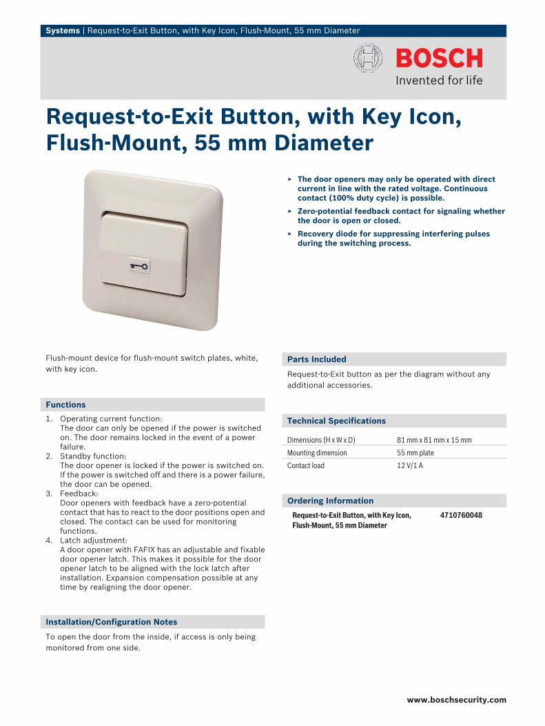
Flush-mount device for flush-mount switch plates, white,with key icon.
Functions
1. Operating current function:The door can only be opened if the power is switchedon. The door remains locked in the event of a powerfailure.
2. Standby function:The door opener is locked if the power is switched on.If the power is switched off and there is a power failure,the door can be opened.
3. Feedback:Door openers with feedback have a zero-potentialcontact that has to react to the door positions open andclosed. The contact can be used for monitoringfunctions.
4. Latch adjustment:A door opener with FAFIX has an adjustable and fixabledoor opener latch. This makes it possible for the dooropener latch to be aligned with the lock latch afterinstallation. Expansion compensation possible at anytime by realigning the door opener.
Installation/Configuration Notes
To open the door from the inside, if access is only beingmonitored from one side.
Parts Included
Request-to-Exit button as per the diagram without anyadditional accessories.
Technical Specifications
Dimensions (H x W x D) 81 mm x 81 mm x 15 mm
Mounting dimension 55 mm plate
Contact load 12 V/1 A
Ordering Information
Request-to-Exit Button, with Key Icon,Flush-Mount, 55 mm Diameter
4710760048
Request-to-Exit Button, with Key Icon,Flush-Mount, 55 mm Diameter
▶ The door openers may only be operated with directcurrent in line with the rated voltage. Continuouscontact (100% duty cycle) is possible.
▶ Zero-potential feedback contact for signaling whetherthe door is open or closed.
▶ Recovery diode for suppressing interfering pulsesduring the switching process.
www.boschsecurity.com
Fire Alarm Systems | FMC‑300RW Single Action Call Points
FMC‑300RW Single Action Call Points www.boschsecurity.com
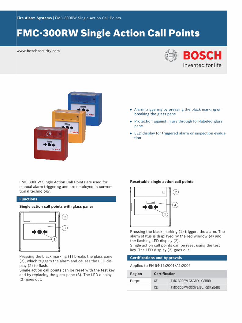
u Alarm triggering by pressing the black marking orbreaking the glass pane
u Protection against injury through foil-labeled glasspane
u LED display for triggered alarm or inspection evalua-tion
FMC‑300RW Single Action Call Points are used formanual alarm triggering and are employed in conven-tional technology.
Functions
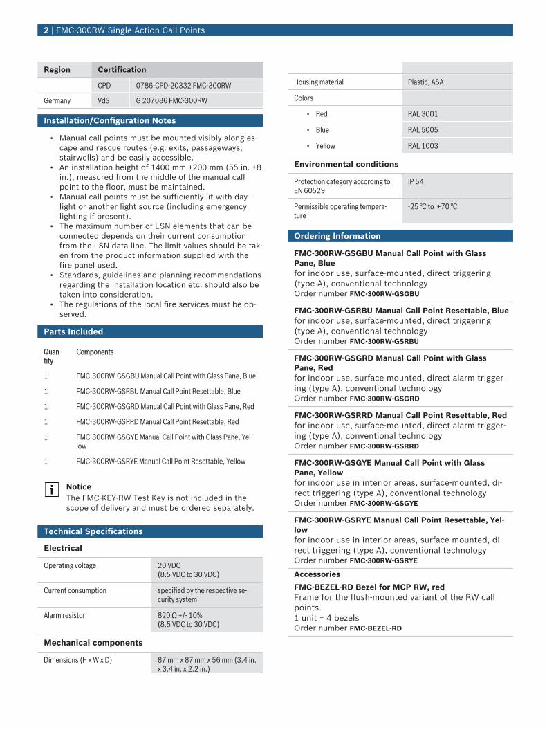
Single action call points with glass pane:
1
2
3
Pressing the black marking (1) breaks the glass pane(3), which triggers the alarm and causes the LED dis-play (2) to flash.Single action call points can be reset with the test keyand by replacing the glass pane (3). The LED display(2) goes out.
Resettable single action call points:
1
2
4
Pressing the black marking (1) triggers the alarm. Thealarm status is displayed by the red window (4) andthe flashing LED display (2).Single action call points can be reset using the testkey. The LED display (2) goes out.
Certifications and Approvals
Applies to EN 54‑11:2001/A1:2005
Region Certification
Europe CE FMC-300RW-GSGRD, -GSRRD
CE FMC-300RW-GSGYE/BU, -GSRYE/BU
Region Certification
CPD 0786-CPD-20332 FMC-300RW
Germany VdS G 207086 FMC-300RW
Installation/Configuration Notes
• Manual call points must be mounted visibly along es-cape and rescue routes (e.g. exits, passageways,stairwells) and be easily accessible.
• An installation height of 1400 mm ±200 mm (55 in. ±8in.), measured from the middle of the manual callpoint to the floor, must be maintained.
• Manual call points must be sufficiently lit with day-light or another light source (including emergencylighting if present).
• The maximum number of LSN elements that can beconnected depends on their current consumptionfrom the LSN data line. The limit values should be tak-en from the product information supplied with thefire panel used.
• Standards, guidelines and planning recommendationsregarding the installation location etc. should also betaken into consideration.
• The regulations of the local fire services must be ob-served.
Parts Included
Quan-tity
Components
1 FMC-300RW-GSGBU Manual Call Point with Glass Pane, Blue
1 FMC-300RW-GSRBU Manual Call Point Resettable, Blue
1 FMC-300RW-GSGRD Manual Call Point with Glass Pane, Red
1 FMC-300RW-GSRRD Manual Call Point Resettable, Red
1 FMC-300RW-GSGYE Manual Call Point with Glass Pane, Yel-low
1 FMC-300RW-GSRYE Manual Call Point Resettable, Yellow
NoticeThe FMC‑KEY‑RW Test Key is not included in thescope of delivery and must be ordered separately.
Technical Specifications
Electrical
Operating voltage 20 VDC(8.5 VDC to 30 VDC)
Current consumption specified by the respective se-curity system
Alarm resistor 820 Ω +/- 10%(8.5 VDC to 30 VDC)
Mechanical components
Dimensions (H x W x D) 87 mm x 87 mm x 56 mm (3.4 in.x 3.4 in. x 2.2 in.)
Housing material Plastic, ASA
Colors
• Red RAL 3001
• Blue RAL 5005
• Yellow RAL 1003
Environmental conditions
Protection category according toEN 60529
IP 54
Permissible operating tempera-ture
-25 °C to +70 °C
Ordering Information
FMC‑300RW‑GSGBU Manual Call Point with GlassPane, Bluefor indoor use, surface-mounted, direct triggering(type A), conventional technologyOrder number FMC-300RW-GSGBU
FMC‑300RW‑GSRBU Manual Call Point Resettable, Bluefor indoor use, surface-mounted, direct triggering(type A), conventional technologyOrder number FMC-300RW-GSRBU
FMC‑300RW‑GSGRD Manual Call Point with GlassPane, Redfor indoor use, surface-mounted, direct alarm trigger-ing (type A), conventional technologyOrder number FMC-300RW-GSGRD
FMC‑300RW‑GSRRD Manual Call Point Resettable, Redfor indoor use, surface-mounted, direct alarm trigger-ing (type A), conventional technologyOrder number FMC-300RW-GSRRD
FMC‑300RW‑GSGYE Manual Call Point with GlassPane, Yellowfor indoor use in interior areas, surface-mounted, di-rect triggering (type A), conventional technologyOrder number FMC-300RW-GSGYE
FMC‑300RW‑GSRYE Manual Call Point Resettable, Yel-lowfor indoor use in interior areas, surface-mounted, di-rect triggering (type A), conventional technologyOrder number FMC-300RW-GSRYE
Accessories
FMC-BEZEL-RD Bezel for MCP RW, redFrame for the flush-mounted variant of the RW callpoints.1 unit = 4 bezelsOrder number FMC-BEZEL-RD
2 | FMC‑300RW Single Action Call Points
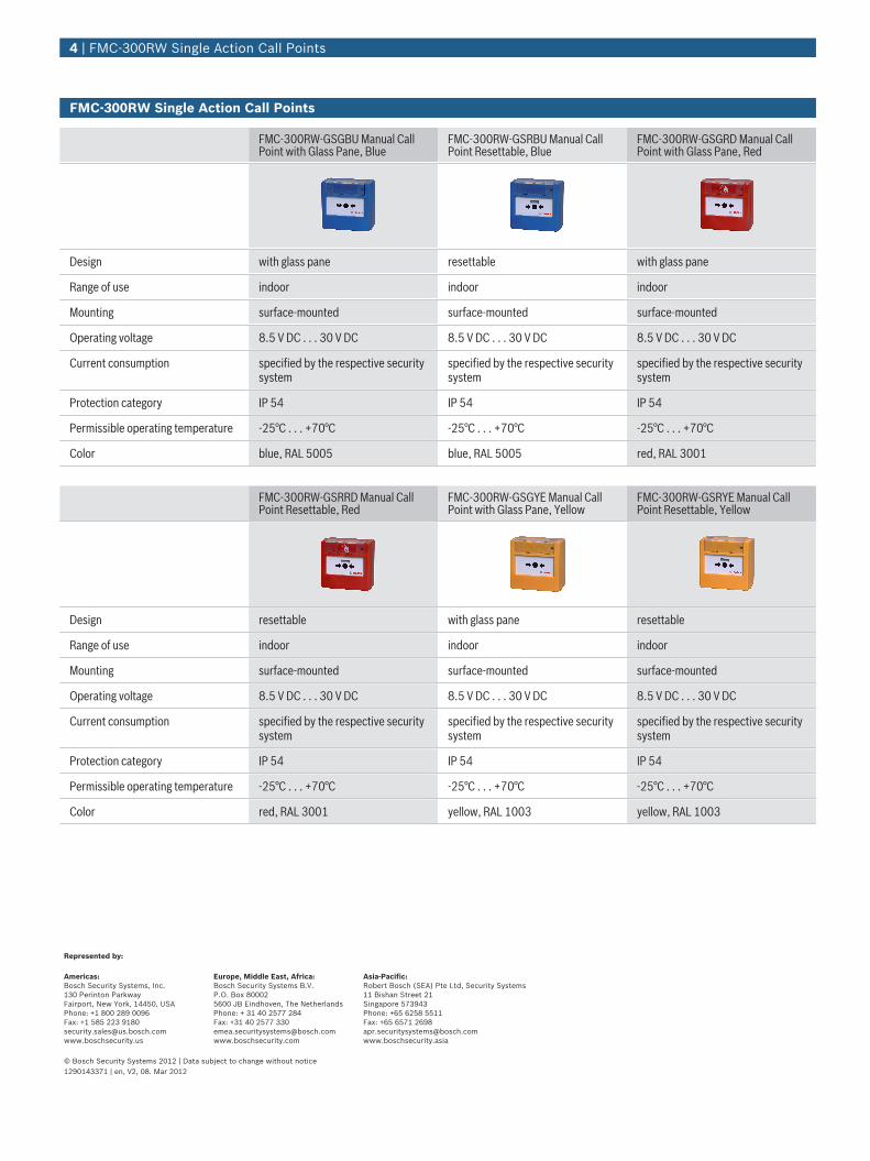
FMC-300RW Single Action Call Points
FMC‑300RW‑GSGBU Manual CallPoint with Glass Pane, Blue
FMC‑300RW‑GSRBU Manual CallPoint Resettable, Blue
FMC‑300RW‑GSGRD Manual CallPoint with Glass Pane, Red
Design with glass pane resettable with glass pane
Range of use indoor indoor indoor
Mounting surface-mounted surface-mounted surface-mounted
Operating voltage 8.5 V DC . . . 30 V DC 8.5 V DC . . . 30 V DC 8.5 V DC . . . 30 V DC
Current consumption specified by the respective securitysystem
specified by the respective securitysystem
specified by the respective securitysystem
Protection category IP 54 IP 54 IP 54
Permissible operating temperature -25°C . . . +70°C -25°C . . . +70°C -25°C . . . +70°C
Color blue, RAL 5005 blue, RAL 5005 red, RAL 3001
FMC‑300RW‑GSRRD Manual CallPoint Resettable, Red
FMC‑300RW‑GSGYE Manual CallPoint with Glass Pane, Yellow
FMC‑300RW‑GSRYE Manual CallPoint Resettable, Yellow
Design resettable with glass pane resettable
Range of use indoor indoor indoor
Mounting surface-mounted surface-mounted surface-mounted
Operating voltage 8.5 V DC . . . 30 V DC 8.5 V DC . . . 30 V DC 8.5 V DC . . . 30 V DC
Current consumption specified by the respective securitysystem
specified by the respective securitysystem
specified by the respective securitysystem
Protection category IP 54 IP 54 IP 54
Permissible operating temperature -25°C . . . +70°C -25°C . . . +70°C -25°C . . . +70°C
Color red, RAL 3001 yellow, RAL 1003 yellow, RAL 1003
4 | FMC‑300RW Single Action Call Points
Represented by:
Americas: Europe, Middle East, Africa: Asia-Pacific: Bosch Security Systems, Inc.130 Perinton ParkwayFairport, New York, 14450, USAPhone: +1 800 289 0096Fax: +1 585 223 [email protected]
Bosch Security Systems B.V.P.O. Box 800025600 JB Eindhoven, The NetherlandsPhone: + 31 40 2577 284Fax: +31 40 2577 [email protected]
Robert Bosch (SEA) Pte Ltd, Security Systems11 Bishan Street 21Singapore 573943Phone: +65 6258 5511Fax: +65 6571 [email protected]
© Bosch Security Systems 2012 | Data subject to change without notice1290143371 | en, V2, 08. Mar 2012

Systems | Universal Electric Door Opener, for DIN Left and Right, Standby Current, 100% Duty Cycle, 12 V DC
Functions
• Operating current function:The door can only be opened if the power is switchedon. The door remains locked in the event of a powerfailure.
• Standby function:The door opener is locked if the power is switched on.If the power is switched off and there is a power failure,the door can be opened.
• Feedback:Door openers with feedback have a zero-potentialcontact that has to react to the door positions open andclosed. The contact can be used for monitoringfunctions.
• Latch adjustment:A door opener with FAFIX has an adjustable and fixabledoor opener latch. This makes it possible for the dooropener latch to be aligned with the lock latch afterinstallation. Expansion compensation possible at anytime by realigning the door opener.
Installation/Configuration Notes
User informationIn line with the pertinent safety regulations, such as theaccident prevention regulations etc., an emergency releasemechanism must also be fitted for exit checks. When usingdoor openers with standby current, an emergency releasemechanism is not required, because the door isautomatically unlocked in the event of a power failure.
Note The dimensional drawings of the door openercorrespond with those of the universal electricdoor opener with operating current.
Parts Included
Door opener as per the diagram without any additionalaccessories.
Universal Electric Door Opener, for DINLeft and Right, Standby Current, 100%Duty Cycle, 12 V DC
▶ The door openers may only be operated with directcurrent in line with the rated voltage. Continuouscontact (100% duty cycle) is possible.
▶ Zero-potential feedback contact for signaling whetherthe door is open or closed.
▶ Recovery diode for suppressing interfering pulsesduring the switching process.
▶ Door opener with normal flat edge plate with bolt cut-out for house and room locks, can be adjusteduniversally for DIN left and right.
▶ Door opener is unlocked without voltage. The door isopened in the event of a power failure.
www.boschsecurity.com

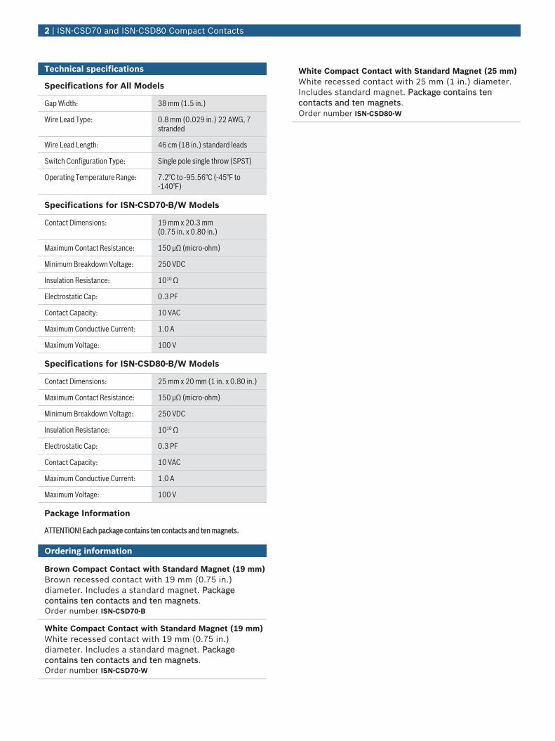
Intrusion Alarm Systems | ISN‑CSD70 and ISN‑CSD80 Compact Contacts
ISN‑CSD70 and ISN‑CSD80Compact Contacts
www.boschsecurity.com
u Closed loop
u Sensitive non-stick rhodium reed
u Bent long leads keep solder off the glass of the reed
u Two solder points on the wire
u Thick plastic shell resists crushing
The contacts are available in brown or white. Allmodels have a rugged, one-piece construction thateliminates the need for extra donut adapters. Thecompact (stubby) design allows you to use the contactin smaller spaces, without paying for a miniaturedesign. Use on steel doors in standard or tight-fittingapplications.
NoticeThe photograph shows model ISN-CSD80-W.
Certifications and approvals
UL and
Region Certification
Europe CE 73/23/EEC and 93/68/EEC, EN50131:1997, EN50131-6: 1997, EN60950:2000, EN60335-1: 1994 +A1: 1996Annex B
USA UL cULus: AMQV: Connectors and Switches(UL 634), AMQV7: Connectors andSwitches Certified for Canada (ULC/ORD-C634) [-CSD70 Series]
UL cULus: AMQV: Connectors and Switches(UL 634), AMQV7: Connectors andSwitches Certified for Canada (ULC/ORD-C634) [-CSD80 Series]
Installation/configuration notes
Compatibility InformationAll contact models are compatible with control panelmodels that accept contact inputs.
Parts included
Quantity Per Package Component
10 Contacts
10 Magnets
Technical specifications
Specifications for All Models
Gap Width: 38 mm (1.5 in.)
Wire Lead Type: 0.8 mm (0.029 in.) 22 AWG, 7stranded
Wire Lead Length: 46 cm (18 in.) standard leads
Switch Configuration Type: Single pole single throw (SPST)
Operating Temperature Range: 7.2°C to -95.56°C (-45°F to-140°F)
Specifications for ISN-CSD70-B/W Models
Contact Dimensions: 19 mm x 20.3 mm(0.75 in. x 0.80 in.)
Maximum Contact Resistance: 150 μΩ (micro-ohm)
Minimum Breakdown Voltage: 250 VDC
Insulation Resistance: 1010 Ω
Electrostatic Cap: 0.3 PF
Contact Capacity: 10 VAC
Maximum Conductive Current: 1.0 A
Maximum Voltage: 100 V
Specifications for ISN-CSD80-B/W Models
Contact Dimensions: 25 mm x 20 mm (1 in. x 0.80 in.)
Maximum Contact Resistance: 150 μΩ (micro-ohm)
Minimum Breakdown Voltage: 250 VDC
Insulation Resistance: 1010 Ω
Electrostatic Cap: 0.3 PF
Contact Capacity: 10 VAC
Maximum Conductive Current: 1.0 A
Maximum Voltage: 100 V
Package Information
ATTENTION! Each package contains ten contacts and ten magnets.
Ordering information
Brown Compact Contact with Standard Magnet (19 mm)Brown recessed contact with 19 mm (0.75 in.)diameter. Includes a standard magnet. Packagecontains ten contacts and ten magnets.Order number ISN-CSD70-B
White Compact Contact with Standard Magnet (19 mm)White recessed contact with 19 mm (0.75 in.)diameter. Includes a standard magnet. Packagecontains ten contacts and ten magnets.Order number ISN-CSD70-W
White Compact Contact with Standard Magnet (25 mm)White recessed contact with 25 mm (1 in.) diameter.Includes standard magnet. Package contains tencontacts and ten magnets.Order number ISN-CSD80-W
2 | ISN‑CSD70 and ISN‑CSD80 Compact Contacts


![Control aCCes – o soluţie fleXibilă Şi eConoMiCă acces-o solutie... · 2012-03-15 · 31 Alarma Arta de a tr^i în siguran]^ numărul 3/2009 Control aCCes – o soluţie fleXibilă](https://img.pdfslide.net/doc/110x75/5e54256f8125a11ee445bd0b/control-acces-a-o-soluie-flexibilf-i-economicf-acces-o-solutie-2012-03-15.jpg)