Embed Size (px)
Citation preview
DATUM ELECTRONICSCOMMERCIAL MARINE TORSION METER HANDBOOK
DATUM ELECTRONICS LIMITED TELEPHONE: +44 (0) 1983 28 28 34 FAX: +44 (0) 1983 28 28 35 EMAIL: [email protected] WEB: www.datum-electronics.co.uk
DATUM ELECTRONICS COMMERCIAL MARINE TORSION METER HANDBOOK 2
CONTENTS
CMTM OVERVIEW 3
System design 3
CMTM SYSTEM SPECIFICATION 3
CMTM system performance and benefits 3
SYSTEM OVERVIEW 3
Standard system overview 3
SYSTEM COMPONENT INFORMATION 4
Transmitter 4
Rotor belt 4
Single point stator 5
Marine controller 5
7-inch display panel 5
SYSTEM ALIGNMENT 6
Mounting instructions 6
SYSTEM FAQS 8
How is torsion meter calibrated? 8
How is power calculated? 8
Can the outputs be changed? 8
Negative displays of torque and power? 8
Torque is shown when there's no RPM? 8
Other concerns 8
SYSTEM DIAGNOSIS 9
Transmitter LEDs 9
Stator LEDs 9
Marine Control Display
CMTM SYSTEM CHECKS 10
Verifying torque output 10
Zero setting 10
Altering system calibration and settings 10
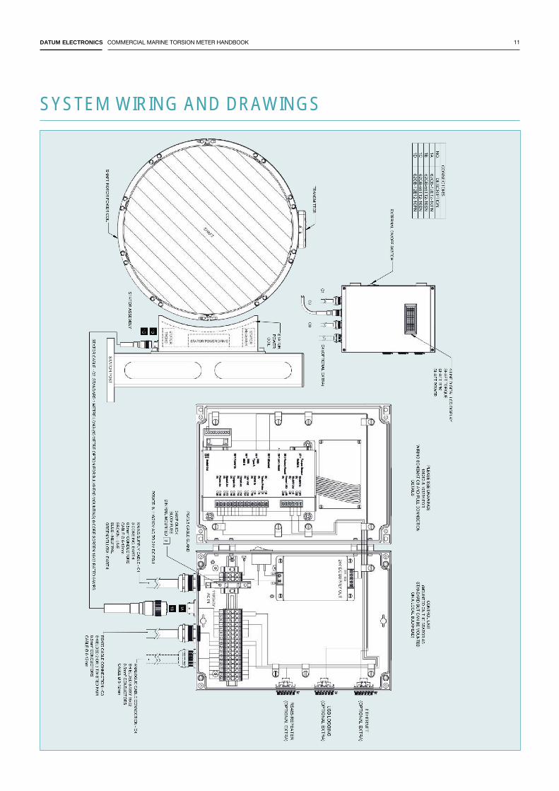
SYSTEM WIRING & DRAWINGS 11
Stator 11
Control unit 11
Digital LCD display 11
Document: 1025 Issue: 1 Date: 20/10/2016
DATUM ELECTRONICS COMMERCIAL MARINE TORSION METER HANDBOOK 3
SYSTEM SPECIFICATIONS CMTM system performancec and benefits:
CMTM OVERVIEW
System design
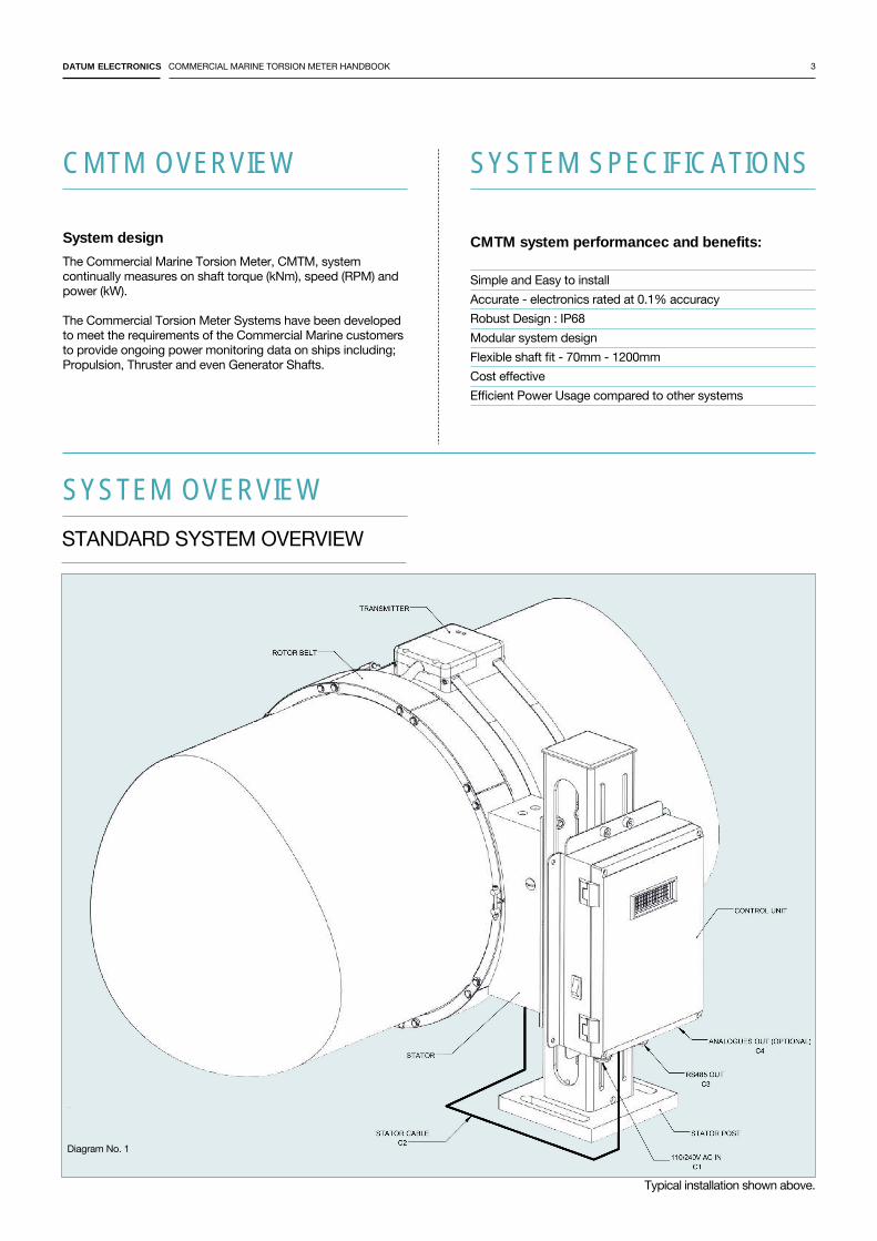
The Commercial Marine Torsion Meter, CMTM, system continually measures on shaft torque (kNm), speed (RPM) and power (kW). The Commercial Torsion Meter Systems have been developed to meet the requirements of the Commercial Marine customers to provide ongoing power monitoring data on ships including; Propulsion, Thruster and even Generator Shafts.
Simple and Easy to install Accurate - electronics rated at 0.1% accuracyRobust Design : IP68Modular system designFlexible shaft fit - 70mm - 1200mmCost effectiveEfficient Power Usage compared to other systems
STANDARD SYSTEM OVERVIEW
Diagram No. 1
SYSTEM OVERVIEW
Typical installation shown above.
DATUM ELECTRONICS COMMERCIAL MARINE TORSION METER HANDBOOK 4
SYSTEM COMPONENT INFORMATION
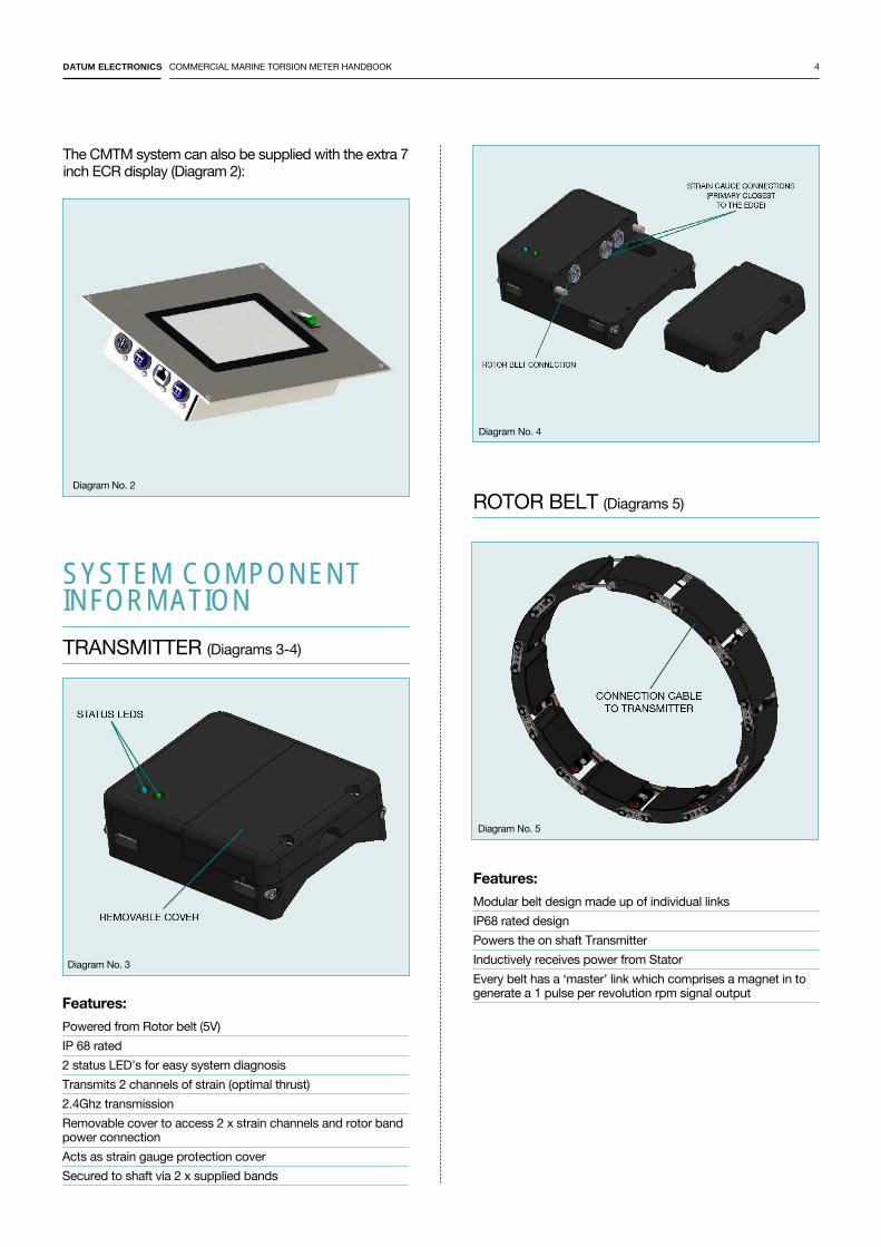
TRANSMITTER (Diagrams 3-4)
The CMTM system can also be supplied with the extra 7 inch ECR display (Diagram 2):
Diagram No. 3
Diagram No. 2
Features:Powered from Rotor belt (5V) IP 68 rated2 status LED’s for easy system diagnosisTransmits 2 channels of strain (optimal thrust)2.4Ghz transmissionRemovable cover to access 2 x strain channels and rotor band power connection Acts as strain gauge protection coverSecured to shaft via 2 x supplied bands
Diagram No. 4
ROTOR BELT (Diagrams 5)
Features:Modular belt design made up of individual links IP68 rated designPowers the on shaft TransmitterInductively receives power from Stator Every belt has a ‘master’ link which comprises a magnet in to generate a 1 pulse per revolution rpm signal output
Diagram No. 5
DATUM ELECTRONICS COMMERCIAL MARINE TORSION METER HANDBOOK 5
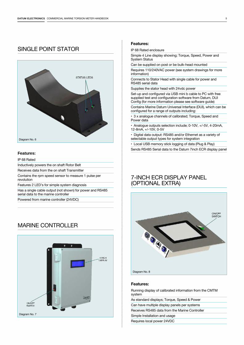
SINGLE POINT STATOR
Features:
IP 68 RatedInductively powers the on shaft Rotor BeltReceives data from the on shaft TransmitterContains the rpm speed sensor to measure 1 pulse per revolutionFeatures 2 LED’s for simple system diagnosisHas a single cable output (not shown) for power and RS485 serial data to the marine controllerPowered from marine controller (24VDC)
MARINE CONTROLLER
Features:IP 68 Rated enclosureSimple 4 Line display showing; Torque, Speed, Power and System StatusCan be supplied on post or be bulk-head mountedRequires 110/240VAC power (see system drawings for more information)Connects to Stator Head with single cable for power and RS485 serial dataSupplies the stator head with 24vdc powerSet-up and configured via USB mini b cable to PC with free supplied test and configuration software from Datum, DUI Config (for more information please see software guide)Contains Marine Datum Universal Interface (DUI), which can be configured for a range of outputs including:• 3 x analogue channels of calibrated; Torque, Speed and Power data• Analogue outputs selection include; 0-10V, +/-5V, 4-20mA, 12-8mA, +/-10V, 0-5V• Digital data output: RS485 and/or Ethernet as a variety of selectable output types for system integration• Local USB memory stick logging of data (Plug & Play)Sends RS485 Serial data to the Datum 7inch ECR display panel
7-INCH ECR DISPLAY PANEL (OPTIONAL EXTRA)
Features:Running display of calibrated information from the CMTM system As standard displays; Torque, Speed & PowerCan have multiple display panels per systemsReceives RS485 data from the Marine ControllerSimple Installation and usageRequires local power 24VDC
Diagram No. 6
Diagram No. 7
Diagram No. 8
DATUM ELECTRONICS COMMERCIAL MARINE TORSION METER HANDBOOK 6
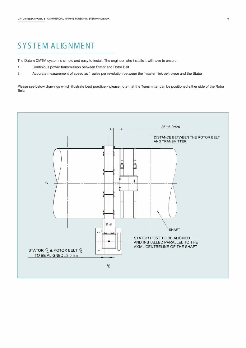
SYSTEM ALIGNMENT
The Datum CMTM system is simple and easy to install. The engineer who installs it will have to ensure:
1. Continious power transmission between Stator and Rotor Belt
2. Accurate measurement of speed as 1 pulse per revolution between the ‘master’ link belt piece and the Stator
Please see below drawings which illustrate best practice – please note that the Transmitter can be positioned either side of the Rotor Belt:
DATUM ELECTRONICS COMMERCIAL MARINE TORSION METER HANDBOOK 7
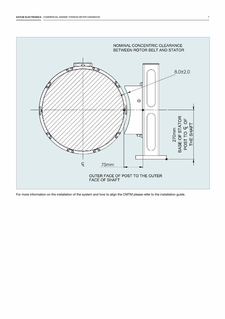
For more information on the installation of the system and how to align the CMTM please refer to the installation guide.
DATUM ELECTRONICS COMMERCIAL MARINE TORSION METER HANDBOOK 8
SYSTEM FAQ'S
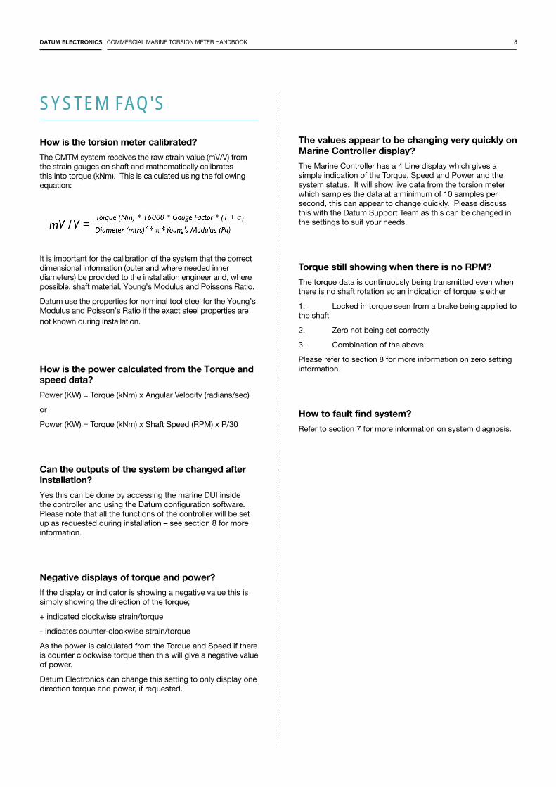
How is the torsion meter calibrated?The CMTM system receives the raw strain value (mV/V) from the strain gauges on shaft and mathematically calibrates this into torque (kNm). This is calculated using the following equation:
It is important for the calibration of the system that the correct dimensional information (outer and where needed inner diameters) be provided to the installation engineer and, where possible, shaft material, Young’s Modulus and Poissons Ratio.
Datum use the properties for nominal tool steel for the Young’s Modulus and Poisson’s Ratio if the exact steel properties are not known during installation.
How is the power calculated from the Torque and speed data?Power (KW) = Torque (kNm) x Angular Velocity (radians/sec)
or
Power (KW) = Torque (kNm) x Shaft Speed (RPM) x P/30
Can the outputs of the system be changed after installation? Yes this can be done by accessing the marine DUI inside the controller and using the Datum configuration software. Please note that all the functions of the controller will be set up as requested during installation – see section 8 for more information.
Negative displays of torque and power?If the display or indicator is showing a negative value this is simply showing the direction of the torque;
+ indicated clockwise strain/torque
- indicates counter-clockwise strain/torque
As the power is calculated from the Torque and Speed if there is counter clockwise torque then this will give a negative value of power.
Datum Electronics can change this setting to only display one direction torque and power, if requested.
The values appear to be changing very quickly on Marine Controller display?
The Marine Controller has a 4 Line display which gives a simple indication of the Torque, Speed and Power and the system status. It will show live data from the torsion meter which samples the data at a minimum of 10 samples per second, this can appear to change quickly. Please discuss this with the Datum Support Team as this can be changed in the settings to suit your needs.
Torque still showing when there is no RPM?The torque data is continuously being transmitted even when there is no shaft rotation so an indication of torque is either
1. Locked in torque seen from a brake being applied to the shaft
2. Zero not being set correctly
3. Combination of the above
Please refer to section 8 for more information on zero setting information.
How to fault find system?Refer to section 7 for more information on system diagnosis.
DATUM ELECTRONICS COMMERCIAL MARINE TORSION METER HANDBOOK 9
MARINE CONTROLLER DISPLAY & 7 INCH DISPLAY
The fourth line of the display alternatively shows the status of the controller as well as the current sample rate. The status will either show as;
• STATUS OK = receiving data from stator and transmitter, followed by samples per second being received
• STATUS no input = not receiving data from stator and transmitter, followed by 0 samples per second
Both the display and controller have a manual power on/off switch which can be used to reset the system. Please note that this will not delete any settings stored into the marine DUI.
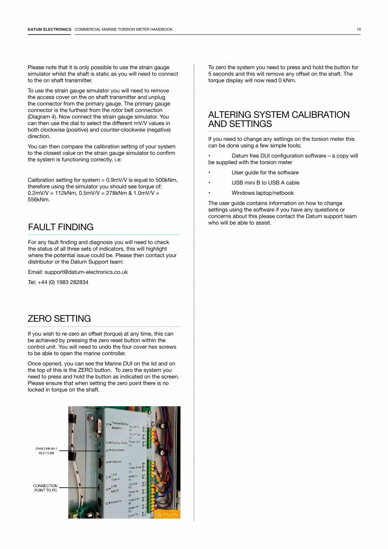
CONFIRMING THE TORQUE OUTPUT
If you are concerned about the amount of torque being displayed and have checked your calibration values then it is possible to prove the CMTM system and its output of torque by replacing the strain gauges with a set of known mV/V values. With every torsion meter Datum Electronics supply a strain gauge simulator which can inject known mV/V steps in both directions of; 0, 0.2. 0.5, 1.0, 1.5 & 2.0 mV/V.
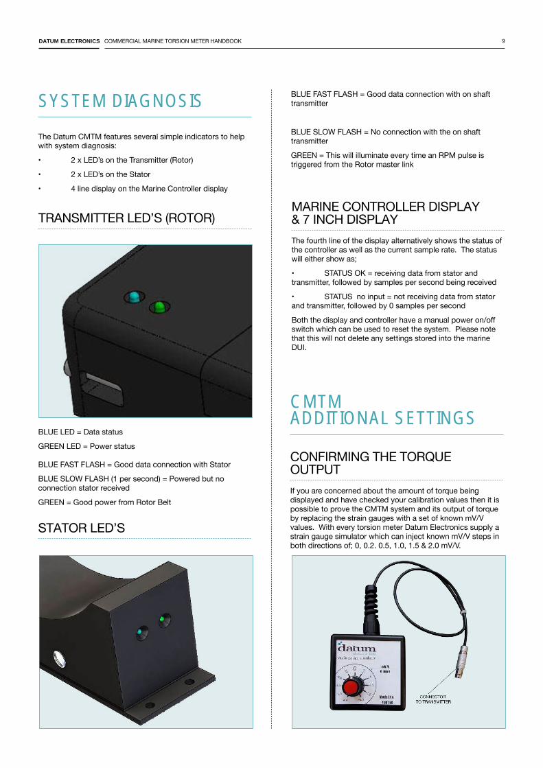
TRANSMITTER LED’S (ROTOR)
BLUE LED = Data status
GREEN LED = Power status BLUE FAST FLASH = Good data connection with Stator
BLUE SLOW FLASH (1 per second) = Powered but no connection stator received
GREEN = Good power from Rotor Belt
STATOR LED’S
The Datum CMTM features several simple indicators to help with system diagnosis:
• 2 x LED’s on the Transmitter (Rotor)
• 2 x LED’s on the Stator
• 4 line display on the Marine Controller display
SYSTEM DIAGNOSIS BLUE FAST FLASH = Good data connection with on shaft transmitter
BLUE SLOW FLASH = No connection with the on shaft transmitter
GREEN = This will illuminate every time an RPM pulse is triggered from the Rotor master link
CMTM ADDITIONAL SETTINGS
DATUM ELECTRONICS COMMERCIAL MARINE TORSION METER HANDBOOK 10
Please note that it is only possible to use the strain gauge simulator whilst the shaft is static as you will need to connect to the on shaft transmitter.
To use the strain gauge simulator you will need to remove the access cover on the on shaft transmitter and unplug the connector from the primary gauge. The primary gauge connector is the furthest from the rotor belt connection (Diagram 4). Now connect the strain gauge simulator. You can then use the dial to select the different mV/V values in both clockwise (positive) and counter-clockwise (negative) direction.
You can then compare the calibration setting of your system to the closest value on the strain gauge simulator to confirm the system is functioning correctly, i.e:
Calibration setting for system = 0.9mV/V is equal to 500kNm, therefore using the simulator you should see torque of; 0.2mV/V = 112kNm, 0.5mV/V = 278kNm & 1.0mV/V = 556kNm.
FAULT FINDING
For any fault finding and diagnosis you will need to check the status of all three sets of indicators, this will highlight where the potential issue could be. Please then contact your distributor or the Datum Support team:
Email: [email protected]
Tel: +44 (0) 1983 282834
ZERO SETTING
If you wish to re-zero an offset (torque) at any time, this can be achieved by pressing the zero reset button within the control unit. You will need to undo the four cover hex screws to be able to open the marine controller.
Once opened, you can see the Marine DUI on the lid and on the top of this is the ZERO button. To zero the system you need to press and hold the button as indicated on the screen. Please ensure that when setting the zero point there is no locked in torque on the shaft.
ALTERING SYSTEM CALIBRATION AND SETTINGS
If you need to change any settings on the torsion meter this can be done using a few simple tools;
• Datum free DUI configuration software – a copy will be supplied with the torsion meter
• User guide for the software
• USB mini B to USB A cable
• Windows laptop/netbook
The user guide contains information on how to change settings using the software if you have any questions or concerns about this please contact the Datum support team who will be able to assist.
To zero the system you need to press and hold the button for 5 seconds and this will remove any offset on the shaft. The torque display will now read 0 kNm.
DATUM ELECTRONICS COMMERCIAL MARINE TORSION METER HANDBOOK 11
SYSTEM WIRING AND DRAWINGS

DATUM ELECTRONICS COMMERCIAL MARINE TORSION METER HANDBOOK 12
DATUM ELECTRONICS LIMITEDTELEPHONE: +44 (0) 1983 28 28 34FAX: +44 (0) 1983 28 28 35EMAIL: [email protected]: www.datum-electronics.co.uk
DESIGNED BY WWW.PEPPERCREATIVE.CO.UK