Embed Size (px)
Citation preview
Datum - This is an arbitrary level surface to which the heights of all points are referred. This may be the National Datum (Australian Height Datum) or local datum point established on a construction site. Mean sea level (MSL) is the average (mean) height of the sea between High and Low tides Reduced Level (RL) – A distance recorded as a Height Above or Below the DATUM. This height is in metres. A benchmark in every-day language is a point of reference for a measurement. In surveying a benchmark is specifically any permanent marker placed by a surveyor with a precisely known vertical elevation (but not necessarily a precisely known horizontal location). These reference points may be chiselled into a wall, or more typically, marked by small brass or aluminium disks, iron pins or bolts that are permanently attached to a stable foundation, such as concrete posts, bridge abutments, buildings, or a specifically constructed concrete block. These markers are then used as starting (control) points by subsequent surveyors and other users to establish the elevation of nearby points. The height of a benchmark is calculated relative to the heights of nearby benchmarks in a network extending from a fundamental datum, a point with a precisely known relationship to the level datum of the area, typically mean sea level.
Australian Height Datum (AHD) The Australian Height Datum is a theoretical reference surface (datum) for altitude measurement in Australia. In 1971 the mean sea level for 1966-1968 was assigned the value of zero on the Australian Height Datum at thirty tide gauges around the coast of the Australian continent. The resulting datum surface, has been termed the Australian Height Datum (AHD) and was adopted as the datum to which all vertical control for mapping (and other surveying functions)
is to be referred.
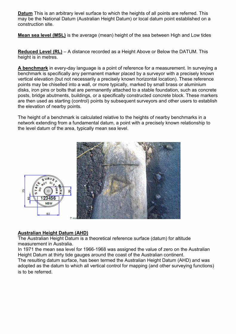
Benchmarks
Tools For Leveling
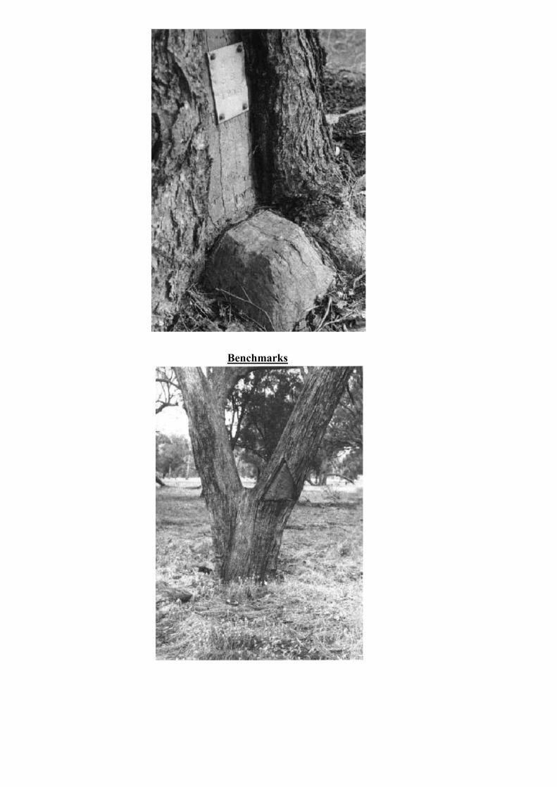
Spirit Level - or bubble level is an instrument designed to indicate whether a surface is level or plumb Line Level - A line level is a level designed to hang on a builder’s string line. The body of the level incorporates small hooks to allow it to attach and hang from the string line. The body is lightweight, so as not to weigh down the string line, it is also small in size as the string line in effect becomes the body; when the level is hung in the center of the string, each leg of the string line extends the levels plane
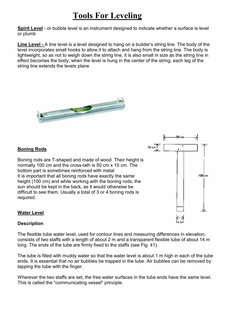
Boning Rods Boning rods are T-shaped and made of wood. Their height is normally 100 cm and the cross-lath is 50 cm x 10 cm. The bottom part is sometimes reinforced with metal It is important that all boning rods have exactly the same height (100 cm) and while working with the boning rods, the sun should be kept in the back, as it would otherwise be difficult to see them. Usually a total of 3 or 4 boning rods is required.
Water Level
Description The flexible tube water level, used for contour lines and measuring differences in elevation, consists of two staffs with a length of about 2 m and a transparent flexible tube of about 14 m long. The ends of the tube are firmly fixed to the staffs (see Fig. 41).
The tube is filled with muddy water so that the water level is about 1 m high in each of the tube ends. It is essential that no air bubbles be trapped in the tube. Air bubbles can be removed by tapping the tube with the finger. Wherever the two staffs are set, the free water surfaces in the tube ends have the same level. This is called the "communicating vessel" principle.
Measuring differences in elevation
For the measurement of differences in elevation between two points in the field, the tube water level is adapted. Each staff is graduated in centimetres and used as a measuring staff. The zero point usually coincides with the foot of the staff.
A. Measuring the difference in elevation between two close points
Suppose the difference in elevation between two points A and B has to be measured; A and B are less than 10 m apart.
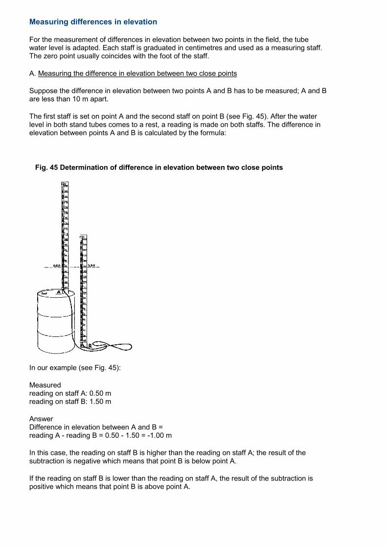
The first staff is set on point A and the second staff on point B (see Fig. 45). After the water level in both stand tubes comes to a rest, a reading is made on both staffs. The difference in elevation between points A and B is calculated by the formula:
Fig. 45 Determination of difference in elevation between two close points
In our example (see Fig. 45):
Measured reading on staff A: 0.50 m reading on staff B: 1.50 m
Answer Difference in elevation between A and B = reading A - reading B = 0.50 - 1.50 = -1.00 m
In this case, the reading on staff B is higher than the reading on staff A; the result of the subtraction is negative which means that point B is below point A.
If the reading on staff B is lower than the reading on staff A, the result of the subtraction is positive which means that point B is above point A.
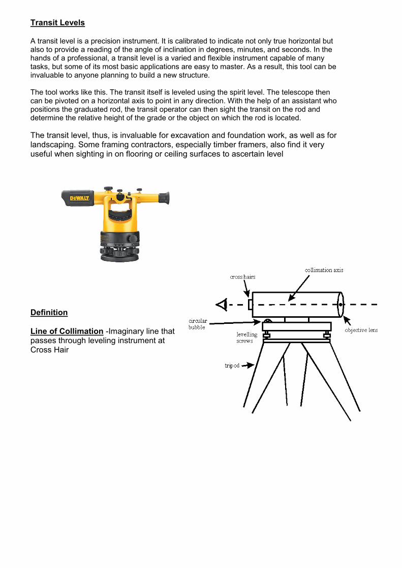
Transit Levels
A transit level is a precision instrument. It is calibrated to indicate not only true horizontal but also to provide a reading of the angle of inclination in degrees, minutes, and seconds. In the hands of a professional, a transit level is a varied and flexible instrument capable of many tasks, but some of its most basic applications are easy to master. As a result, this tool can be invaluable to anyone planning to build a new structure. The tool works like this. The transit itself is leveled using the spirit level. The telescope then can be pivoted on a horizontal axis to point in any direction. With the help of an assistant who positions the graduated rod, the transit operator can then sight the transit on the rod and determine the relative height of the grade or the object on which the rod is located.
The transit level, thus, is invaluable for excavation and foundation work, as well as for landscaping. Some framing contractors, especially timber framers, also find it very useful when sighting in on flooring or ceiling surfaces to ascertain level
Definition
Line of Collimation -Imaginary line that passes through leveling instrument at Cross Hair
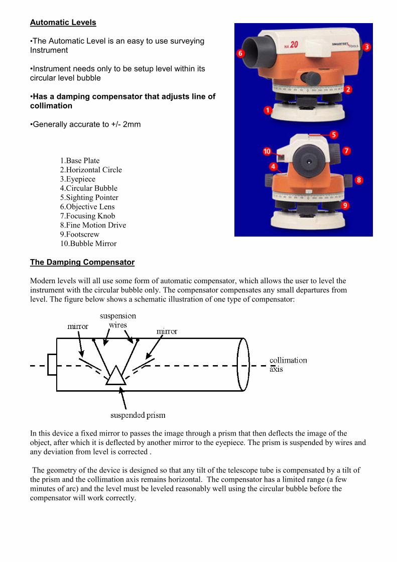
Automatic Levels
•The Automatic Level is an easy to use surveying Instrument
•Instrument needs only to be setup level within its circular level bubble
•Has a damping compensator that adjusts line of collimation
•Generally accurate to +/- 2mm
1.Base Plate
2.Horizontal Circle
3.Eyepiece
4.Circular Bubble
5.Sighting Pointer
6.Objective Lens
7.Focusing Knob
8.Fine Motion Drive
9.Footscrew
10.Bubble Mirror
The Damping Compensator
Modern levels will all use some form of automatic compensator, which allows the user to level the
instrument with the circular bubble only. The compensator compensates any small departures from
level. The figure below shows a schematic illustration of one type of compensator:
In this device a fixed mirror to passes the image through a prism that then deflects the image of the
object, after which it is deflected by another mirror to the eyepiece. The prism is suspended by wires and
any deviation from level is corrected .
The geometry of the device is designed so that any tilt of the telescope tube is compensated by a tilt of
the prism and the collimation axis remains horizontal. The compensator has a limited range (a few
minutes of arc) and the level must be leveled reasonably well using the circular bubble before the
compensator will work correctly.
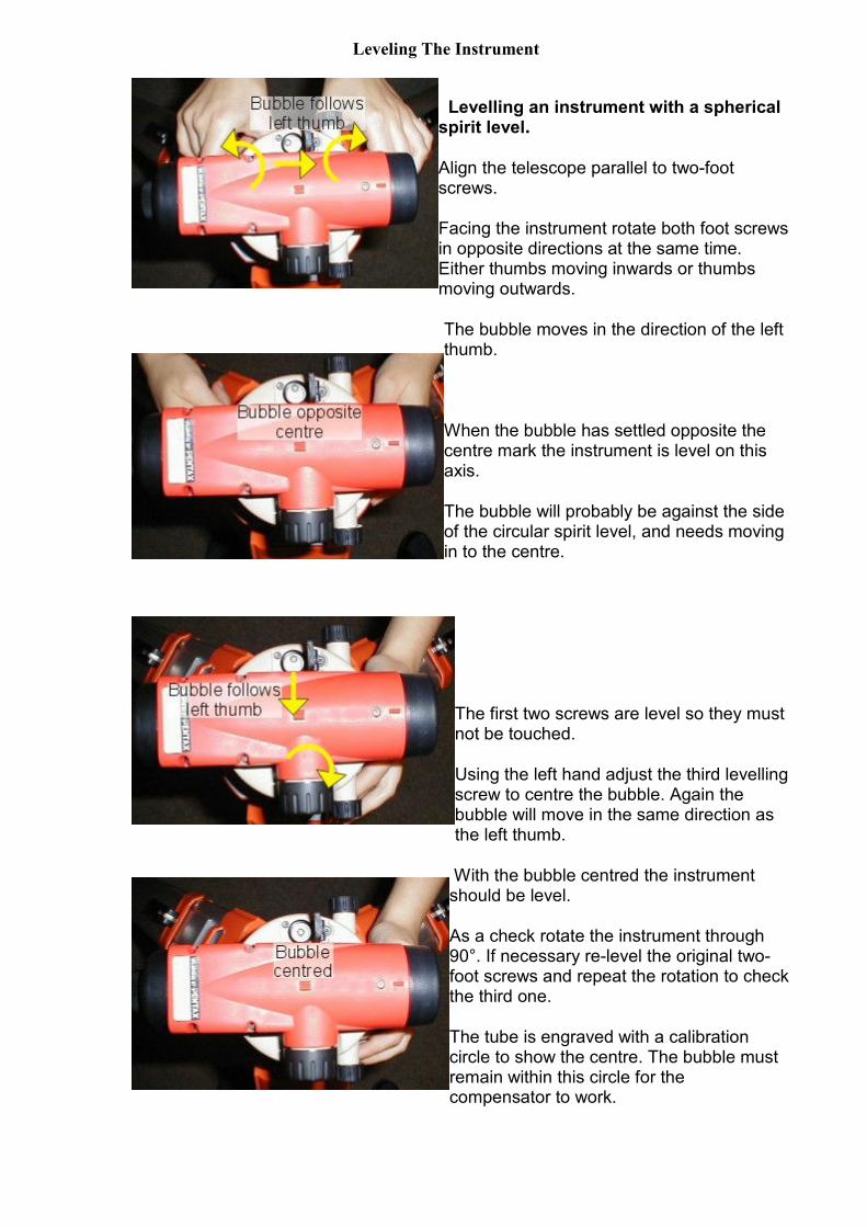
Leveling The Instrument
Levelling an instrument with a spherical spirit level.
Align the telescope parallel to two-foot screws.
Facing the instrument rotate both foot screws in opposite directions at the same time. Either thumbs moving inwards or thumbs moving outwards.
The bubble moves in the direction of the left thumb.
When the bubble has settled opposite the centre mark the instrument is level on this axis.
The bubble will probably be against the side of the circular spirit level, and needs moving in to the centre.
The first two screws are level so they must not be touched.
Using the left hand adjust the third levelling screw to centre the bubble. Again the bubble will move in the same direction as the left thumb.
With the bubble centred the instrument should be level.
As a check rotate the instrument through 90°. If necessary re-level the original two-foot screws and repeat the rotation to check the third one.
The tube is engraved with a calibration circle to show the centre. The bubble must remain within this circle for the compensator to work.
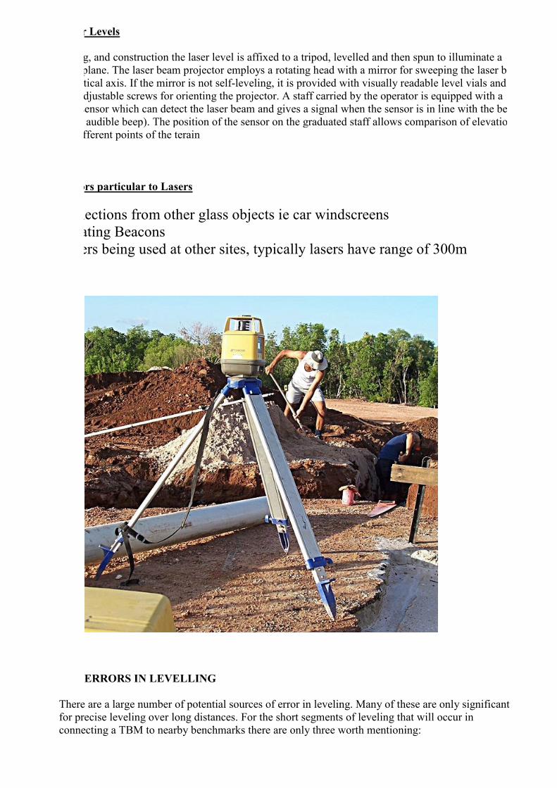
Laser Levels
surveying, and construction the laser level is affixed to a tripod, levelled and then spun to illuminate a
horizontal plane. The laser beam projector employs a rotating head with a mirror for sweeping the laser beam
about a vertical axis. If the mirror is not self-leveling, it is provided with visually readable level vials and
manually adjustable screws for orienting the projector. A staff carried by the operator is equipped with a
moveable sensor which can detect the laser beam and gives a signal when the sensor is in line with the beam
(usually an audible beep). The position of the sensor on the graduated staff allows comparison of elevations
between different points of the terain
Errors particular to Lasers
Reflections from other glass objects ie car windscreens
Rotating Beacons
Lasers being used at other sites, typically lasers have range of 300m
ERRORS IN LEVELLING
There are a large number of potential sources of error in leveling. Many of these are only significant
for precise leveling over long distances. For the short segments of leveling that will occur in
connecting a TBM to nearby benchmarks there are only three worth mentioning:
• Collimation Error
• Parallax Error
• Error due to Earth Curvature
• Error due to Refraction
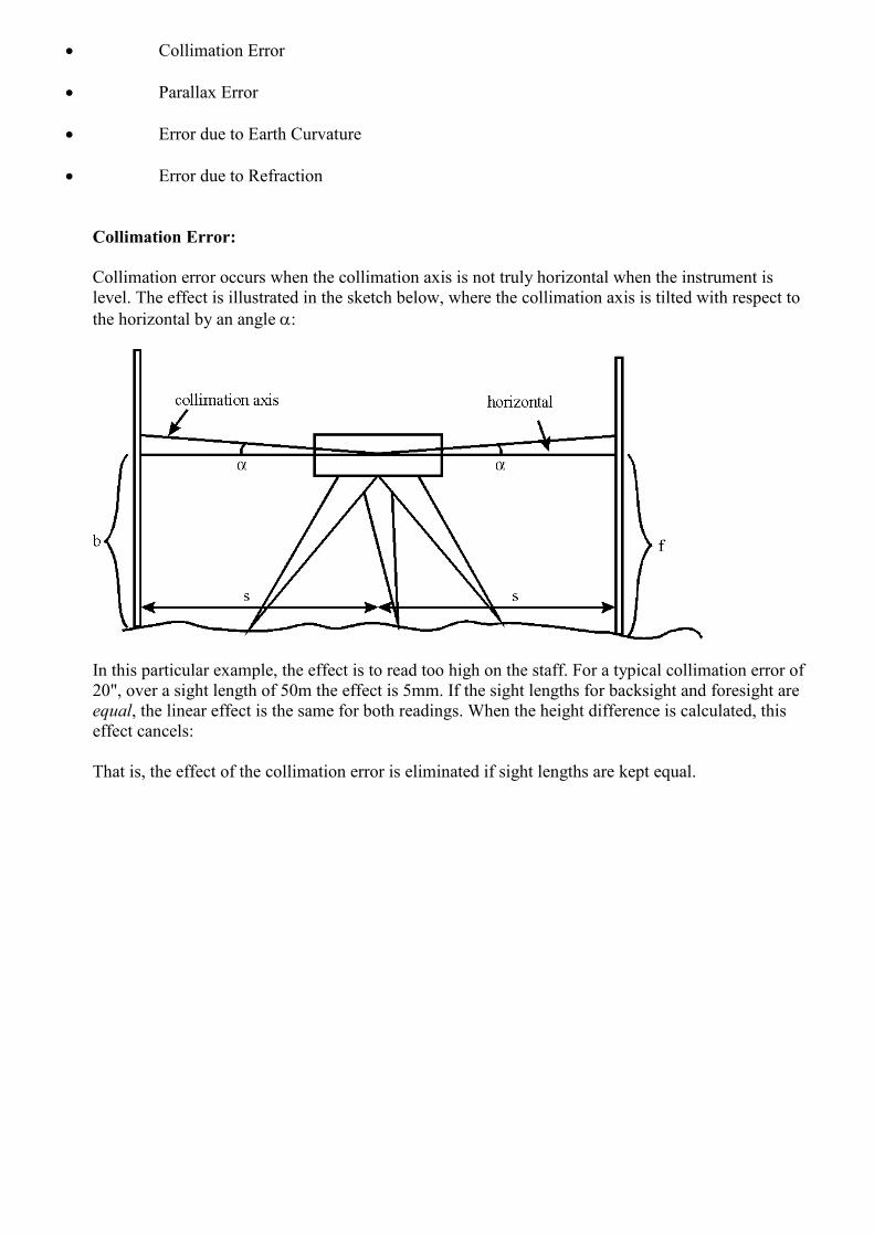
Collimation Error:
Collimation error occurs when the collimation axis is not truly horizontal when the instrument is
level. The effect is illustrated in the sketch below, where the collimation axis is tilted with respect to
the horizontal by an angle α:
In this particular example, the effect is to read too high on the staff. For a typical collimation error of
20", over a sight length of 50m the effect is 5mm. If the sight lengths for backsight and foresight are
equal, the linear effect is the same for both readings. When the height difference is calculated, this
effect cancels:
That is, the effect of the collimation error is eliminated if sight lengths are kept equal.
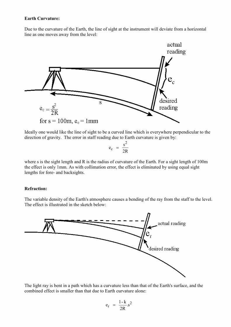
Earth Curvature:
Due to the curvature of the Earth, the line of sight at the instrument will deviate from a horizontal
line as one moves away from the level:
Ideally one would like the line of sight to be a curved line which is everywhere perpendicular to the
direction of gravity. The error in staff reading due to Earth curvature is given by:
2R
s e
2
c =
where s is the sight length and R is the radius of curvature of the Earth. For a sight length of 100m
the effect is only 1mm. As with collimation error, the effect is eliminated by using equal sight
lengths for fore- and backsights.
Refraction:
The variable density of the Earth's atmosphere causes a bending of the ray from the staff to the level.
The effect is illustrated in the sketch below:
The light ray is bent in a path which has a curvature less than that of the Earth's surface, and the
combined effect is smaller than that due to Earth curvature alone:
2r s.
2R
k - 1 e =
Here, k is the coefficient of refraction and represents the ratio of the radius of curvature of the Earth
to the radius of curvature of the light path. An average value of k is 0.13, from which:
er = 0.068.10-3.s2
where s is in metres and er in millimetres. For example, for s = 100m, er = 0.7mm.
The effect of refraction is almost totally eliminated by using equal fore- and backsights (because
atmospheric conditions along the fore- and backsights will not be completely identical, there will be
a small residual error).
Parallax Error
When using an optical instrument — both the image and cross hairs can be focused- if
either is imprecisely focused, the cross hairs will appear to move with respect to the
object focused, if one moves one's head horizontally in front of the eyepiece.
This is why it is important, especially when performing measurements, to carefully
focus both the image and cross hairs in order to 'eliminate the parallax', and to check
by moving one's head when taking readings.
DETERMINATION OF COLLIMATION ERROR (Two Peg Test)
Collimation error is much more significant than the other errors. It should be kept as small as
possible so that one need not be too precise in ensuring that fore- and backsights are of equal length
(these are usually paced out). It is possible to determine the collimation error and reduce its size
using the so-called Two-peg test. There are three steps involved in this procedure:
1. Set out and mark on the ground (with wooden pegs driven into the earth, or roofing nails in tar) two
point some 30m apart. Set up the level exactly mid-way (within 0.5m) between them:
Take measurements of backsight and foresight for this first setup. The height difference δh1 will be
free of the effects of collimation error:
δh1 = b1 - f1 = (b + sb.α) - (f + sf.α)
= b - f + α.(sb - sf)
= b - f (because sb = sf )
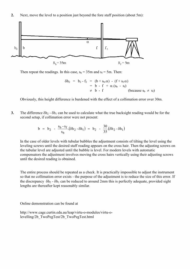
2. Next, move the level to a position just beyond the fore staff position (about 5m):
Then repeat the readings. In this case, sb = 35m and sf = 5m. Then:
δh2 = b2 - f2 = (b + sb.α) - (f + sf.α)
= b - f + α.(sb - sf)
≠ b - f (because sb ≠ sf)
Obviously, this height difference is burdened with the effect of a collimation error over 30m.
3. The difference δh2 - δh1 can be used to calculate what the true backsight reading would be for the
second setup, if collimation error were not present:
( ) ( )12212b
fb2 h - h.
35
30 - b h - h.
s
s - s - b b δδ=δδ=
In the case of older levels with tubular bubbles the adjustment consists of tilting the level using the
leveling screws until the desired staff reading appears on the cross hair. Then the adjusting screws on
the tubular level are adjusted until the bubble is level. For modern levels with automatic
compensators the adjustment involves moving the cross hairs vertically using their adjusting screws
until the desired reading is obtained.
The entire process should be repeated as a check. It is practically impossible to adjust the instrument
so that no collimation error exists - the purpose of the adjustment is to reduce the size of this error. If
the discrepancy δh2 - δh1 can be reduced to around 2mm this is perfectly adequate, provided sight
lengths are thereafter kept reasonably similar.
Online demonstration can be found at
http://www.cage.curtin.edu.au/leap/virtu-o-modules/virtu-o-
levelling/2b_TwoPegTest/2b_TwoPegTest.html
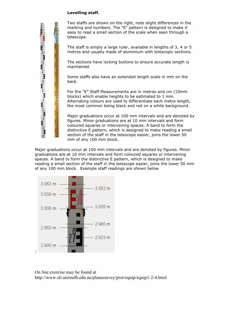
Levelling staff.
Two staffs are shown on the right, note slight differences in the
marking and numbers. The "E" pattern is designed to make it
easy to read a small section of the scale when seen through a
telescope.
The staff is simply a large ruler, available in lengths of 3, 4 or 5 metres and usually made of aluminium with telescopic sections.
The sections have locking buttons to ensure accurate length is maintained.
Some staffs also have an extended length scale in mm on the back.
For the “E” Staff Measurements are in metres and cm (10mm
blocks) which enable heights to be estimated to 1 mm.
Alternating colours are used to differentiate each metre length, the most common being black and red on a white background.
Major graduations occur at 100 mm intervals and are denoted by
figures. Minor graduations are at 10 mm intervals and form
coloured squares or intervening spaces. A band to form the
distinctive E pattern, which is designed to make reading a small
section of the staff in the telescope easier, joins the lower 50
mm of any 100 mm block.
Major graduations occur at 100 mm intervals and are denoted by figures. Minor
graduations are at 10 mm intervals and form coloured squares or intervening
spaces. A band to form the distinctive E pattern, which is designed to make
reading a small section of the staff in the telescope easier, joins the lower 50 mm
of any 100 mm block. Example staff readings are shown below
:
On line exercise may be found at
http://www.sli.unimelb.edu.au/planesurvey/prot/equip/equip1-2-4.html
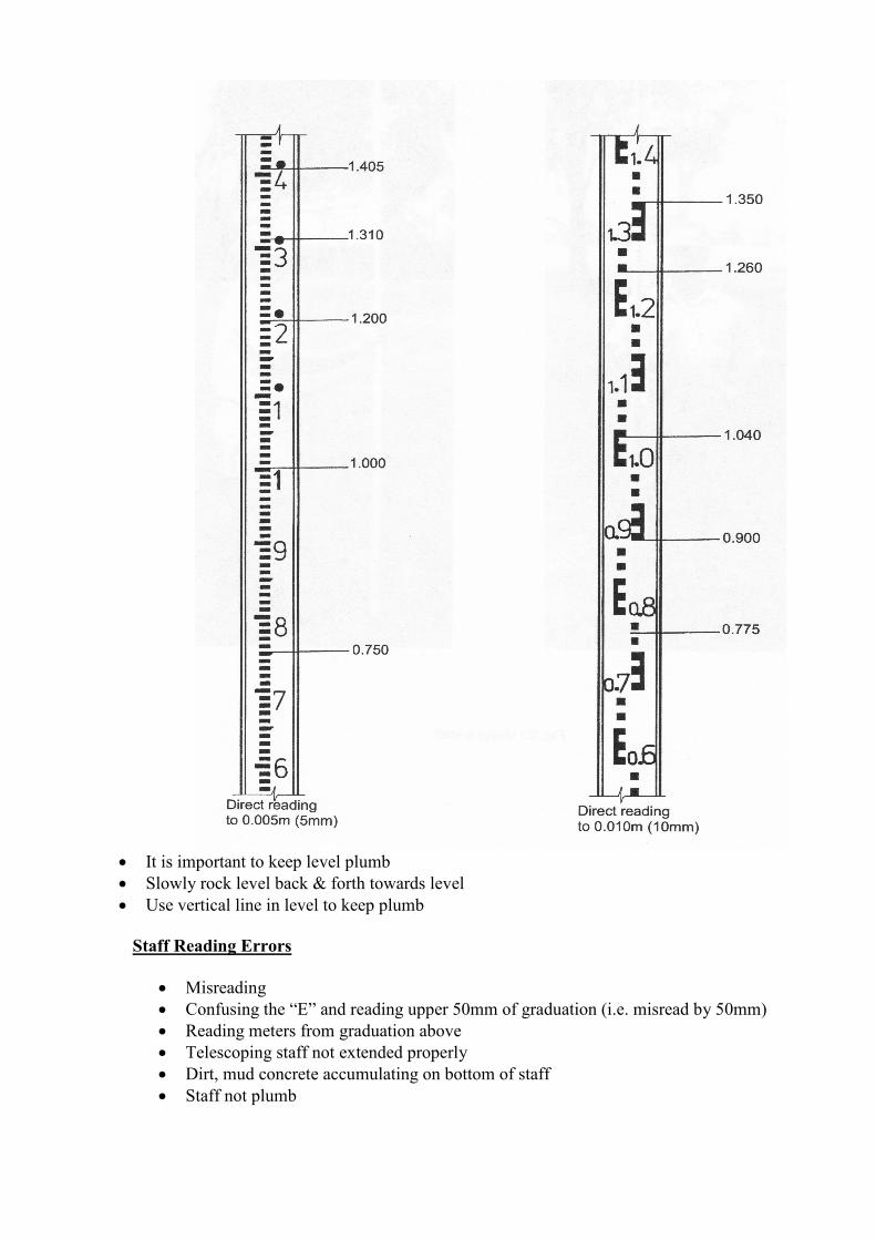
• It is important to keep level plumb
• Slowly rock level back & forth towards level
• Use vertical line in level to keep plumb
Staff Reading Errors
• Misreading
• Confusing the “E” and reading upper 50mm of graduation (i.e. misread by 50mm)
• Reading meters from graduation above
• Telescoping staff not extended properly
• Dirt, mud concrete accumulating on bottom of staff
• Staff not plumb
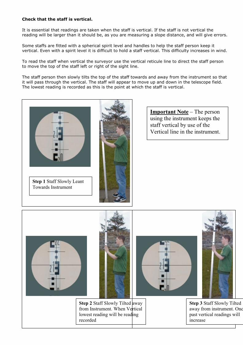
Check that the staff is vertical.
It is essential that readings are taken when the staff is vertical. If the staff is not vertical the reading will be larger than it should be, as you are measuring a slope distance, and will give errors.
Some staffs are fitted with a spherical spirit level and handles to help the staff person keep it vertical. Even with a spirit level it is difficult to hold a staff vertical. This difficulty increases in wind.
To read the staff when vertical the surveyor use the vertical reticule line to direct the staff person to move the top of the staff left or right of the sight line.
The staff person then slowly tilts the top of the staff towards and away from the instrument so that
it will pass through the vertical. The staff will appear to move up and down in the telescope field. The lowest reading is recorded as this is the point at which the staff is vertical.
Step 1 Staff Slowly Leant
Towards Instrument
Step 2 Staff Slowly Tilted away
from Instrument. When Vertical
lowest reading will be reading
recorded
Step 3 Staff Slowly Tilted
away from instrument. Once
past vertical readings will
increase
Important Note – The person
using the instrument keeps the
staff vertical by use of the
Vertical line in the instrument.
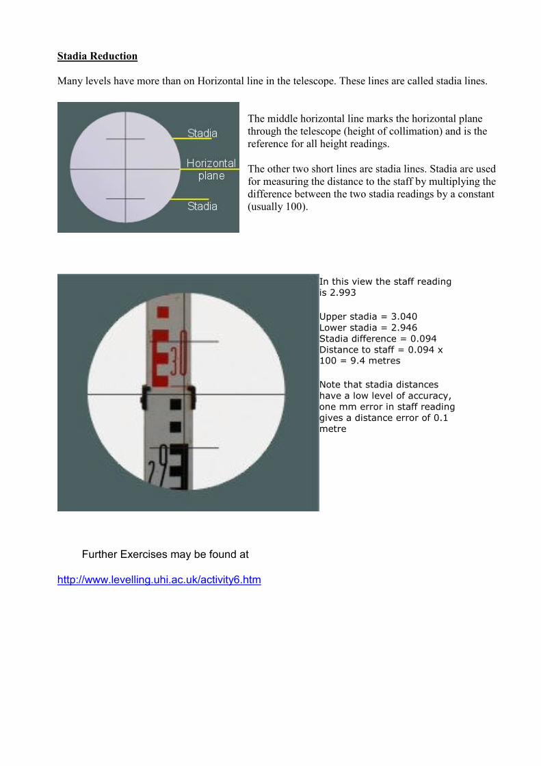
Stadia Reduction
Many levels have more than on Horizontal line in the telescope. These lines are called stadia lines.
The middle horizontal line marks the horizontal plane
through the telescope (height of collimation) and is the
reference for all height readings.
The other two short lines are stadia lines. Stadia are used
for measuring the distance to the staff by multiplying the
difference between the two stadia readings by a constant
(usually 100).
In this view the staff reading
is 2.993
Upper stadia = 3.040
Lower stadia = 2.946
Stadia difference = 0.094
Distance to staff = 0.094 x 100 = 9.4 metres
Note that stadia distances
have a low level of accuracy,
one mm error in staff reading
gives a distance error of 0.1
metre
Further Exercises may be found at
http://www.levelling.uhi.ac.uk/activity6.htm
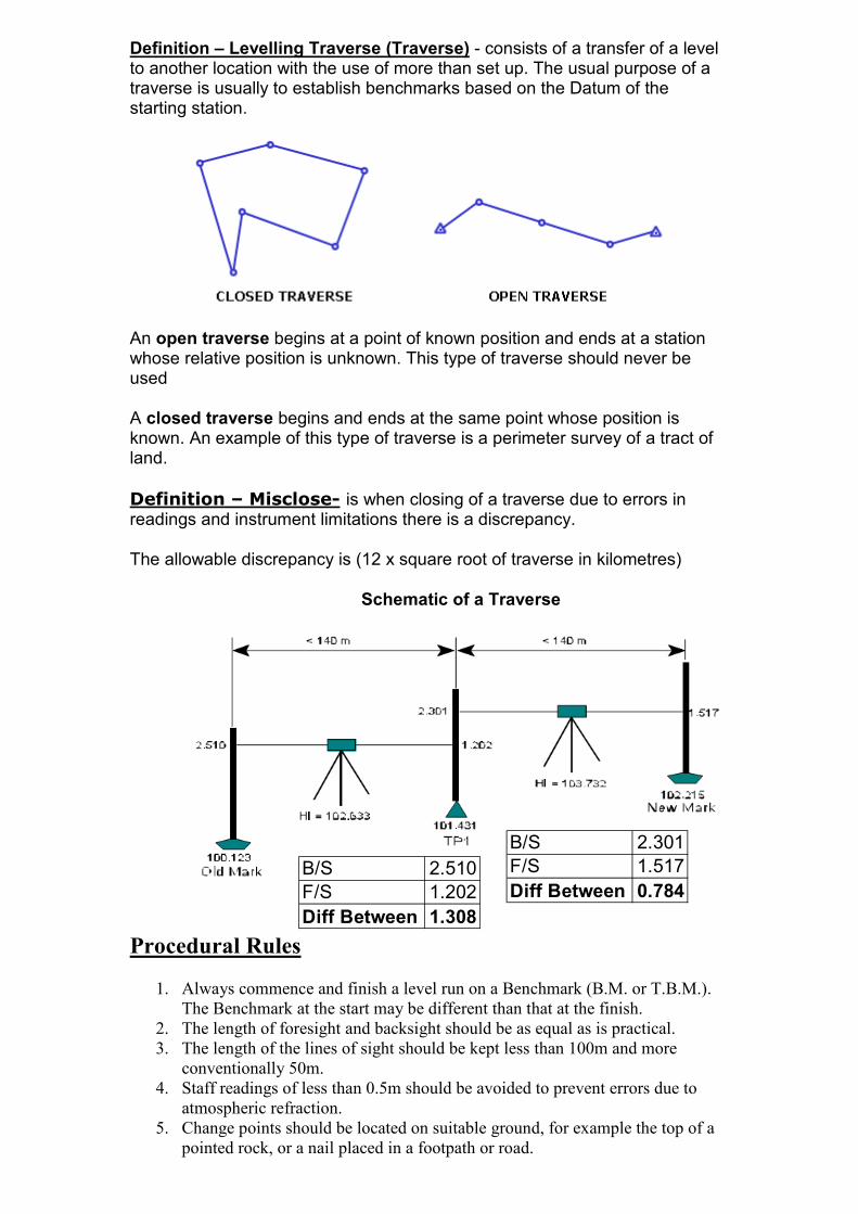
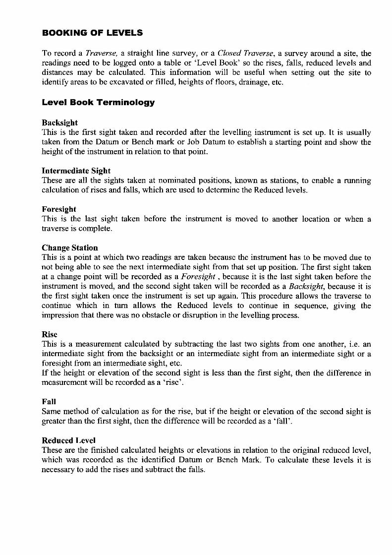
Definition – Levelling Traverse (Traverse) - consists of a transfer of a level to another location with the use of more than set up. The usual purpose of a traverse is usually to establish benchmarks based on the Datum of the starting station.
An open traverse begins at a point of known position and ends at a station whose relative position is unknown. This type of traverse should never be used
A closed traverse begins and ends at the same point whose position is known. An example of this type of traverse is a perimeter survey of a tract of land.
Definition – Misclose- is when closing of a traverse due to errors in readings and instrument limitations there is a discrepancy.
The allowable discrepancy is (12 x square root of traverse in kilometres)
Schematic of a Traverse
Procedural Rules
1. Always commence and finish a level run on a Benchmark (B.M. or T.B.M.). The Benchmark at the start may be different than that at the finish.
2. The length of foresight and backsight should be as equal as is practical. 3. The length of the lines of sight should be kept less than 100m and more
conventionally 50m.
4. Staff readings of less than 0.5m should be avoided to prevent errors due to atmospheric refraction.
5. Change points should be located on suitable ground, for example the top of a pointed rock, or a nail placed in a footpath or road.
B/S 2.510
F/S 1.202
Diff Between 1.308
B/S 2.301
F/S 1.517
Diff Between 0.784