Embed Size (px)
Citation preview
David A. Walenga Technical Assignment #1 Structural Option Structural Concepts Residence Inn by Marriott, Stamford CT October 8, 2003 Professor Parfitt
Page 1 of 21
Executive Summary Contained in this report is design information related to the structural system of the Residence Inn by Marriot located in Stamford, Connecticut. Specifically, this report covers: code usage, gravity loading, lateral loading, types of structural systems and spot checks of representative structural members applying loads determined here within. Codes and Standards The design for the Residence Inn is governed by the BOCA 1996 Code and the accompanying 1999 Connecticut Supplement with the 2000 Amendments. In addition, the structural design is governed by the AISC LRFD Second Edition and ACI 318-99. Applicable ASTM Standards are cited as governing requirements for materials. Gravity Loads Gravity loads used in design are determined by BOCA 1996 in conjunction with ASCE 7-95. In general, material dead loads are determined using industry standard assumption and published material weights. Live loads come directly from code. Lateral Loads Wind and seismic loading are found through provisions set by the BOCA Code. At this stage it is difficult to determine which lateral load type controls the design of the lateral system since the maximum shear loads for individual floors are neither all wind nor seismic values. Structural System The Residence Inn by Marriott is designed as a steel framed structure with precast concrete plank flooring. This type of construction is very common in hotel construction due to its relative ease/speed of construction and cost. Typical spans are 22’-0” and most floor to floor heights are 10’-6”. Standard framing member sizes are W10’s, W12’s and W14’s. Lateral forces are resisted by means of concentrically located braced frames. Member Spot Check Generally, re-designed members using the recalculated loads match the design of the original members very closely. Discrepancies arise due to differing design ideologies, specifically in regards to limiting deflection. The lateral check is done very approximately, however results follow expected behavior in regards to stress and deflection behavior.
David A. Walenga Technical Assignment #1 Structural Option Structural Concepts Residence Inn by Marriott, Stamford CT October 8, 2003 Professor Parfitt
Page 2 of 21
Structural System Description and Summary Foundation System The foundation system for the Stamford Residence Inn is divided in two distinctive areas; each covering approximately half of the building’s overall footprint. The basement level slab elevation is twelve feet below grade and lies under the eastern half of the structure. The basement walls are designed to resist soil pressure and to carry the ground level slenderwall cladding system. Perimeter column foundations are spread footings and strip footings run between the spread footings to transfer the basement wall loads. The majority of the interior columns in the basement area transfer into mat foundations. Two main factors forced the use of mat footings. The first is the close proximity of the columns is not conducive to spread footings; therefore the use of mat footings would be more efficient. Secondly, the majority of the interior columns in the basement are part of the lateral system. A mat footing can resist overturning moments produced by lateral loads more effectively than spread footings as a result of the added mass and dual action. The ground floor foundation is very similar to the basement foundation. Gravity columns transfer loads to spread footings while the lateral system columns transfer to mat footings. The reasoning for the usage of mat and spread footings is the same as those in the basement. One primary difference between the ground level foundation system and the basement system is the allowable soil pressure. Foundations below the basement are on soils with an allowable pressure of 10 ksf whereas foundations below the ground floor sit on soils with an allowable pressure of 6 ksf. Gravity System Steel framed construction with hollow core precast plank flooring is the selected system for the Residence Inn. This type of construction is very typical for hotels due to ease and speed of construction and its cost is comparable to other systems. Typical spans are 22’-0” and almost all non-typical spans are shorter than 22’-0”. The flooring system is constructed with eight inch hollow core precast concrete planks. Generally, planks span east-west on the western half of the structure and north-south on the eastern side of the structure. Typical beams are W14’s and W10’s, while typical columns are W12’s and W10’s. Floors nine through thirteen feature cantilevered balconies on the southeast corner of the building. Eight inch solid precast concrete plank is used on the balconies and moment connections are used to connect the cantilevered beams in these areas.
David A. Walenga Technical Assignment #1 Structural Option Structural Concepts Residence Inn by Marriott, Stamford CT October 8, 2003 Professor Parfitt
Page 3 of 21
Composite steel construction is used for the mezzanine level that is suspended from the second floor. The mezzanine level consists only of a corridor providing access between the two elevators. Composite construction is appropriate to keep the suspended weight low and to keep within the restricted depth set forth by architectural needs. See Appendix A for a typical floor plan. Lateral System The primary lateral force resisting system of the hotel is concentrically located steel braced frames. In all, eight braced frames comprise the lateral system of the structure. Two frames are located at the western end of the structure while the balance of the frames are on the eastern side. Frames are located at the stairwells, elevator shafts and mechanical closet. These locations are ideal as the least amount of obstructions and usable floor area depreciation will be caused by the bracing. Typical beam sizes range from W8’s to W18’s. Column sizes are limited to W12’s and W14’s. Bracing is accomplished with hollow structural sections (HSS), which range in size from 12x8’s, 8x8’s, and 6x6’s. Design of a lateral system for this structure is not ideal due the locations frames are limited to be in. See Appendix B for a typical frame elevation and plan showing frame locations. Miscellaneous Structural Elements Below is a description of non-typical or special structural features requiring special design attention at a later time.
1. Cast-in-place concrete parking garage access ramp located at the southeast corner of the building will need to be analyzed. With the exception of the foundations and elevator room slab the ramp is the only cast-in-place concrete portion of the structure. The ramp is a one way system and no portion of the hotel is supported above the ramp; the ramp roof is at the mezzanine level.
2. Cantilevered balconies on floors nine through thirteen are not part of the typical
gravity frame and need to be analyzed separately. Moment connections are needed for these cantilevered members.
3. Cladding and exterior walls, including glazing system are subjected to lateral
loads, particularly wind.
4. Cantilevered front balcony at main entrance on east side of building applies significant moment and torsion to interior connecting members and will require specific design attention.
David A. Walenga Technical Assignment #1 Structural Option Structural Concepts Residence Inn by Marriott, Stamford CT October 8, 2003 Professor Parfitt
Page 4 of 21
5. Foundation system, specifically mat foundations need to be analyzed. Mat
foundations require considerably more effort in design than typical spread footings especially when columns loading into mat foundations are subjected to lateral loads.
6. Drifted snow load and roof uplift caused by wind loads apply non-typical loads to
roofs which require further design consideration than that of gravity analysis using material weight and superimposed dead and live loads.
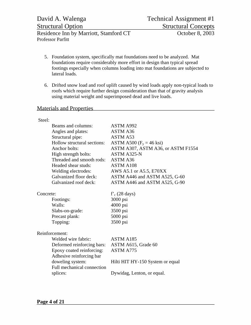
Materials and Properties Steel: Beams and columns: ASTM A992 Angles and plates: ASTM A36 Structural pipe: ASTM A53 Hollow structural sections: ASTM A500 (Fy = 46 ksi) Anchor bolts: ASTM A307, ASTM A36, or ASTM F1554 High strength bolts: ASTM A325-N Threaded and smooth rods: ASTM A36 Headed shear studs: ASTM A108 Welding electrodes: AWS A5.1 or A5.5, E70XX Galvanized floor deck: ASTM A446 and ASTM A525, G-60 Galvanized roof deck: ASTM A446 and ASTM A525, G-90 Concrete: f’c (28 days) Footings: 3000 psi Walls: 4000 psi Slabs-on-grade: 3500 psi Precast plank: 5000 psi Topping: 3500 psi Reinforcement: Welded wire fabric: ASTM A185 Deformed reinforcing bars: ASTM A615, Grade 60 Epoxy coated reinforcing: ASTM A775 Adhesive reinforcing bar doweling system: Hilti HIT HY-150 System or equal Full mechanical connection splices: Dywidag, Lenton, or equal.
David A. Walenga Technical Assignment #1 Structural Option Structural Concepts Residence Inn by Marriott, Stamford CT October 8, 2003 Professor Parfitt
Page 5 of 21
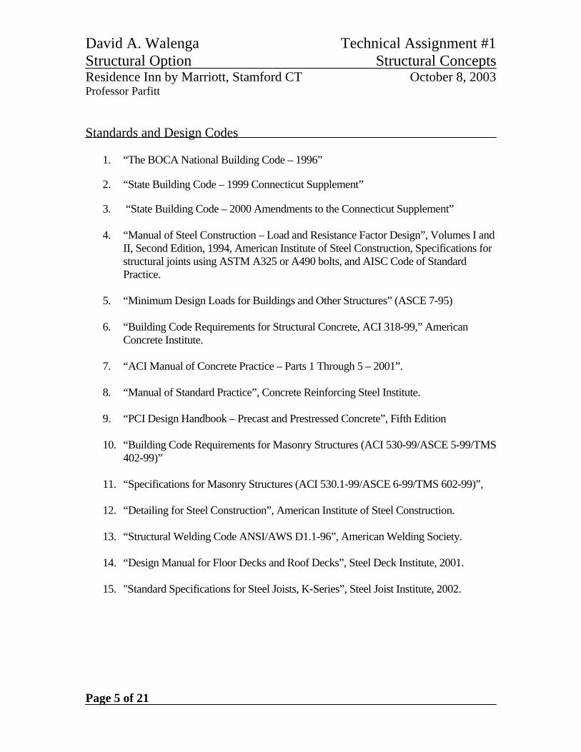
Standards and Design Codes
1. “The BOCA National Building Code – 1996”
2. “State Building Code – 1999 Connecticut Supplement”
3. “State Building Code – 2000 Amendments to the Connecticut Supplement”
4. “Manual of Steel Construction – Load and Resistance Factor Design”, Volumes I and II, Second Edition, 1994, American Institute of Steel Construction, Specifications for structural joints using ASTM A325 or A490 bolts, and AISC Code of Standard Practice.
5. “Minimum Design Loads for Buildings and Other Structures” (ASCE 7-95)
6. “Building Code Requirements for Structural Concrete, ACI 318-99,” American
Concrete Institute.
7. “ACI Manual of Concrete Practice – Parts 1 Through 5 – 2001”.
8. “Manual of Standard Practice”, Concrete Reinforcing Steel Institute.
9. “PCI Design Handbook – Precast and Prestressed Concrete”, Fifth Edition
10. “Building Code Requirements for Masonry Structures (ACI 530-99/ASCE 5-99/TMS 402-99)”
11. “Specifications for Masonry Structures (ACI 530.1-99/ASCE 6-99/TMS 602-99)”,
12. “Detailing for Steel Construction”, American Institute of Steel Construction.
13. “Structural Welding Code ANSI/AWS D1.1-96”, American Welding Society.
14. “Design Manual for Floor Decks and Roof Decks”, Steel Deck Institute, 2001.
15. "Standard Specifications for Steel Joists, K-Series”, Steel Joist Institute, 2002.
David A. Walenga Technical Assignment #1 Structural Option Structural Concepts Residence Inn by Marriott, Stamford CT October 8, 2003 Professor Parfitt
Page 6 of 21
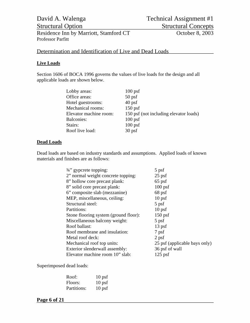
Determination and Identification of Live and Dead Loads Live Loads Section 1606 of BOCA 1996 governs the values of live loads for the design and all applicable loads are shown below.
Lobby areas: 100 psf Office areas: 50 psf Hotel guestrooms: 40 psf Mechanical rooms: 150 psf Elevator machine room: 150 psf (not including elevator loads) Balconies: 100 psf Stairs: 100 psf Roof live load: 30 psf Dead Loads Dead loads are based on industry standards and assumptions. Applied loads of known materials and finishes are as follows: ¾” gypcrete topping: 5 psf 2” normal weight concrete topping: 25 psf 8” hollow core precast plank: 65 psf 8” solid core precast plank: 100 psf 6” composite slab (mezzanine) 68 psf MEP, miscellaneous, ceiling: 10 psf Structural steel: 5 psf Partitions: 10 psf Stone flooring system (ground floor): 150 psf Miscellaneous balcony weight: 5 psf Roof ballast: 13 psf Roof membrane and insulation: 7 psf Metal roof deck: 2 psf Mechanical roof top units: 25 psf (applicable bays only) Exterior slenderwall assembly: 36 psf of wall Elevator machine room 10” slab: 125 psf Superimposed dead loads: Roof: 10 psf Floors: 10 psf Partitions: 10 psf
David A. Walenga Technical Assignment #1 Structural Option Structural Concepts Residence Inn by Marriott, Stamford CT October 8, 2003 Professor Parfitt
Page 7 of 21
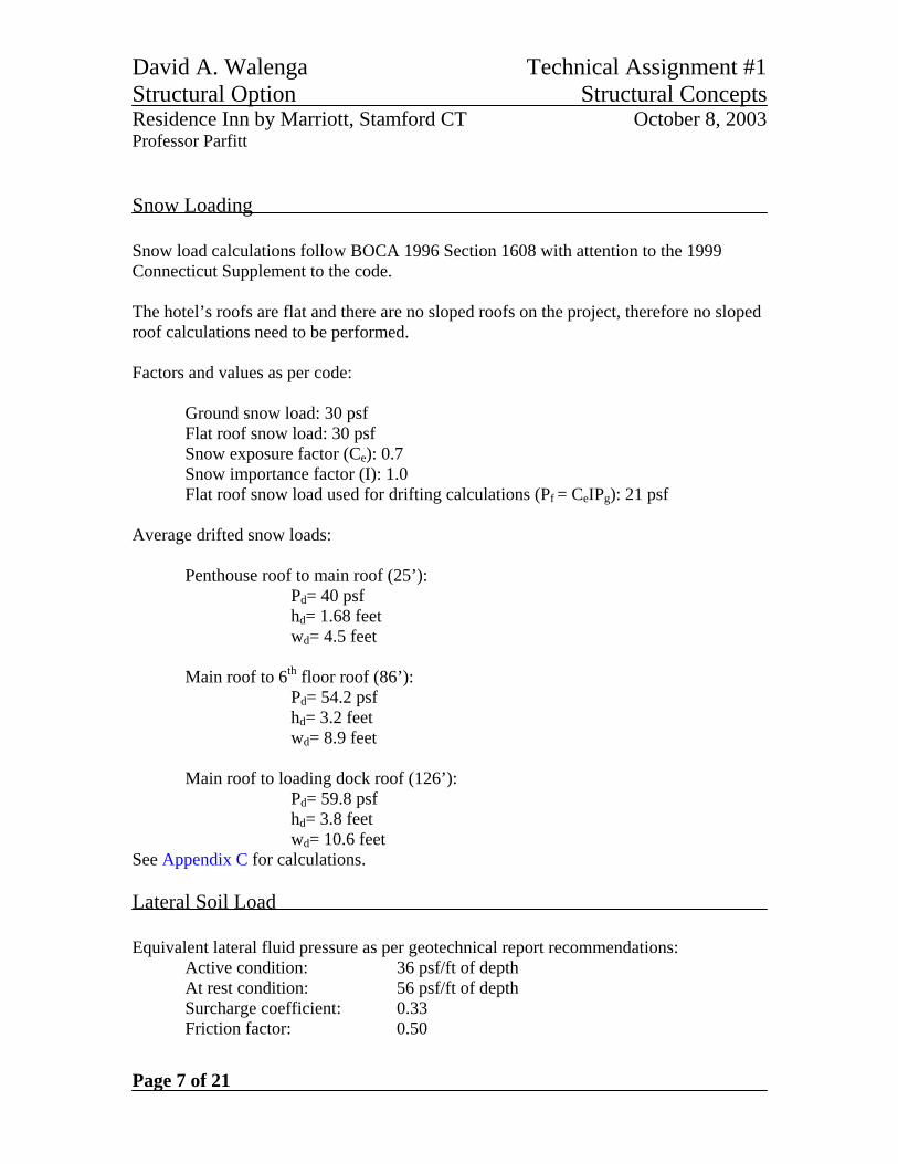
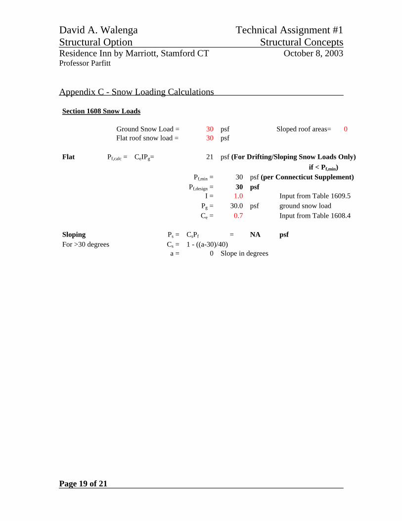
Snow Loading Snow load calculations follow BOCA 1996 Section 1608 with attention to the 1999 Connecticut Supplement to the code. The hotel’s roofs are flat and there are no sloped roofs on the project, therefore no sloped roof calculations need to be performed. Factors and values as per code: Ground snow load: 30 psf Flat roof snow load: 30 psf Snow exposure factor (Ce): 0.7 Snow importance factor (I): 1.0 Flat roof snow load used for drifting calculations (Pf = CeIPg): 21 psf Average drifted snow loads: Penthouse roof to main roof (25’):
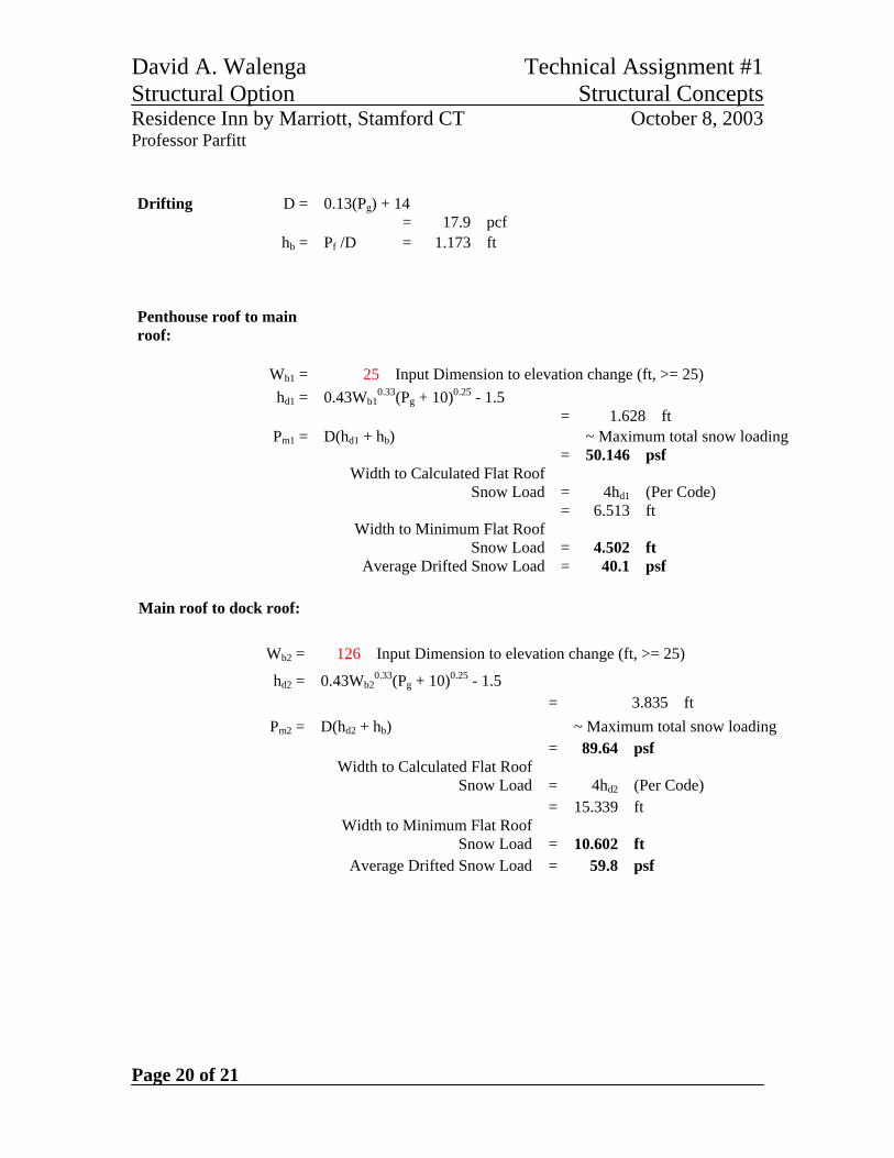
Pd= 40 psf hd= 1.68 feet wd= 4.5 feet
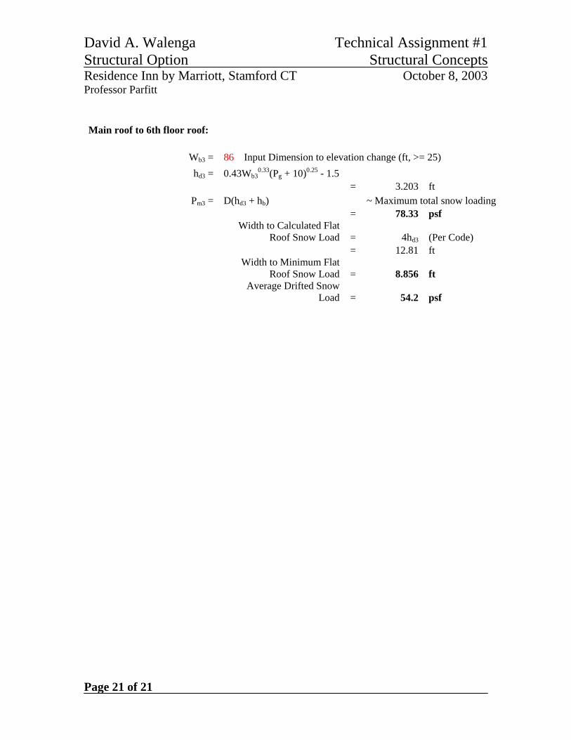
Main roof to 6th floor roof (86’): Pd= 54.2 psf hd= 3.2 feet wd= 8.9 feet
Main roof to loading dock roof (126’): Pd= 59.8 psf hd= 3.8 feet wd= 10.6 feet
See Appendix C for calculations.
Lateral Soil Load
Equivalent lateral fluid pressure as per geotechnical report recommendations: Active condition: 36 psf/ft of depth At rest condition: 56 psf/ft of depth
Surcharge coefficient: 0.33 Friction factor: 0.50
David A. Walenga Technical Assignment #1 Structural Option Structural Concepts Residence Inn by Marriott, Stamford CT October 8, 2003 Professor Parfitt
Page 8 of 21
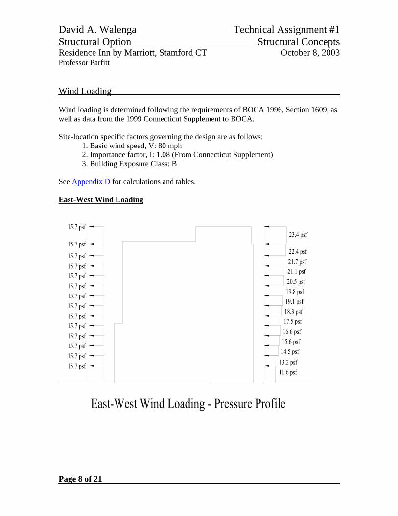
Wind Loading Wind loading is determined following the requirements of BOCA 1996, Section 1609, as well as data from the 1999 Connecticut Supplement to BOCA. Site-location specific factors governing the design are as follows:
1. Basic wind speed, V: 80 mph 2. Importance factor, I: 1.08 (From Connecticut Supplement) 3. Building Exposure Class: B
See Appendix D for calculations and tables. East-West Wind Loading
David A. Walenga Technical Assignment #1 Structural Option Structural Concepts Residence Inn by Marriott, Stamford CT October 8, 2003 Professor Parfitt
Page 9 of 21
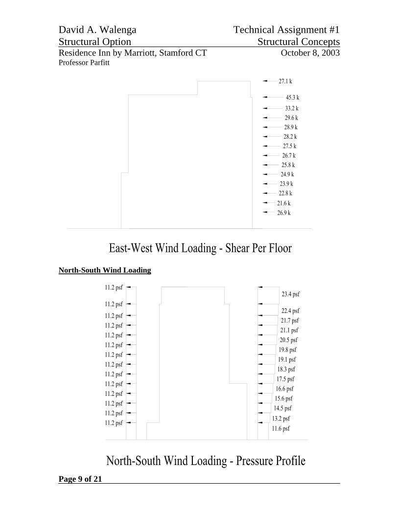
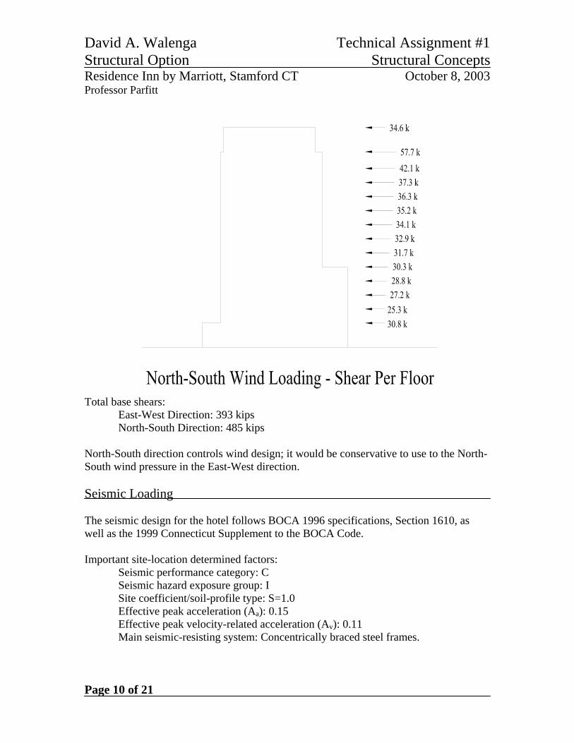
North-South Wind Loading
David A. Walenga Technical Assignment #1 Structural Option Structural Concepts Residence Inn by Marriott, Stamford CT October 8, 2003 Professor Parfitt
Page 10 of 21
Total base shears: East-West Direction: 393 kips North-South Direction: 485 kips North-South direction controls wind design; it would be conservative to use to the North-South wind pressure in the East-West direction. Seismic Loading The seismic design for the hotel follows BOCA 1996 specifications, Section 1610, as well as the 1999 Connecticut Supplement to the BOCA Code. Important site-location determined factors: Seismic performance category: C Seismic hazard exposure group: I Site coefficient/soil-profile type: S=1.0 Effective peak acceleration (Aa): 0.15 Effective peak velocity-related acceleration (Av): 0.11 Main seismic-resisting system: Concentrically braced steel frames.
David A. Walenga Technical Assignment #1 Structural Option Structural Concepts Residence Inn by Marriott, Stamford CT October 8, 2003 Professor Parfitt
Page 11 of 21
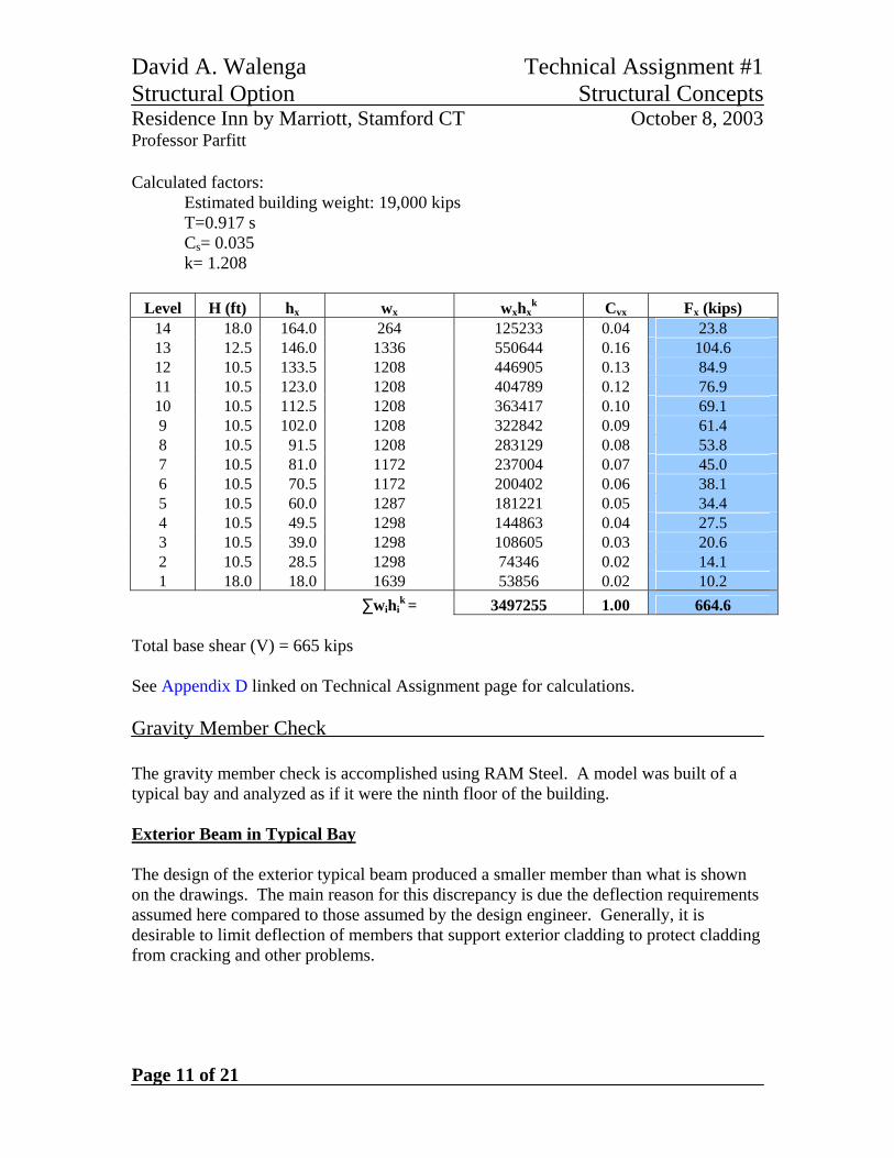
Calculated factors: Estimated building weight: 19,000 kips
T=0.917 s Cs= 0.035 k= 1.208
Level H (ft) hx wx wxhxk Cvx Fx (kips)
14 18.0 164.0 264 125233 0.04 23.8 13 12.5 146.0 1336 550644 0.16 104.6 12 10.5 133.5 1208 446905 0.13 84.9 11 10.5 123.0 1208 404789 0.12 76.9 10 10.5 112.5 1208 363417 0.10 69.1 9 10.5 102.0 1208 322842 0.09 61.4 8 10.5 91.5 1208 283129 0.08 53.8 7 10.5 81.0 1172 237004 0.07 45.0 6 10.5 70.5 1172 200402 0.06 38.1 5 10.5 60.0 1287 181221 0.05 34.4 4 10.5 49.5 1298 144863 0.04 27.5 3 10.5 39.0 1298 108605 0.03 20.6 2 10.5 28.5 1298 74346 0.02 14.1 1 18.0 18.0 1639 53856 0.02 10.2
∑wihik = 3497255 1.00 664.6
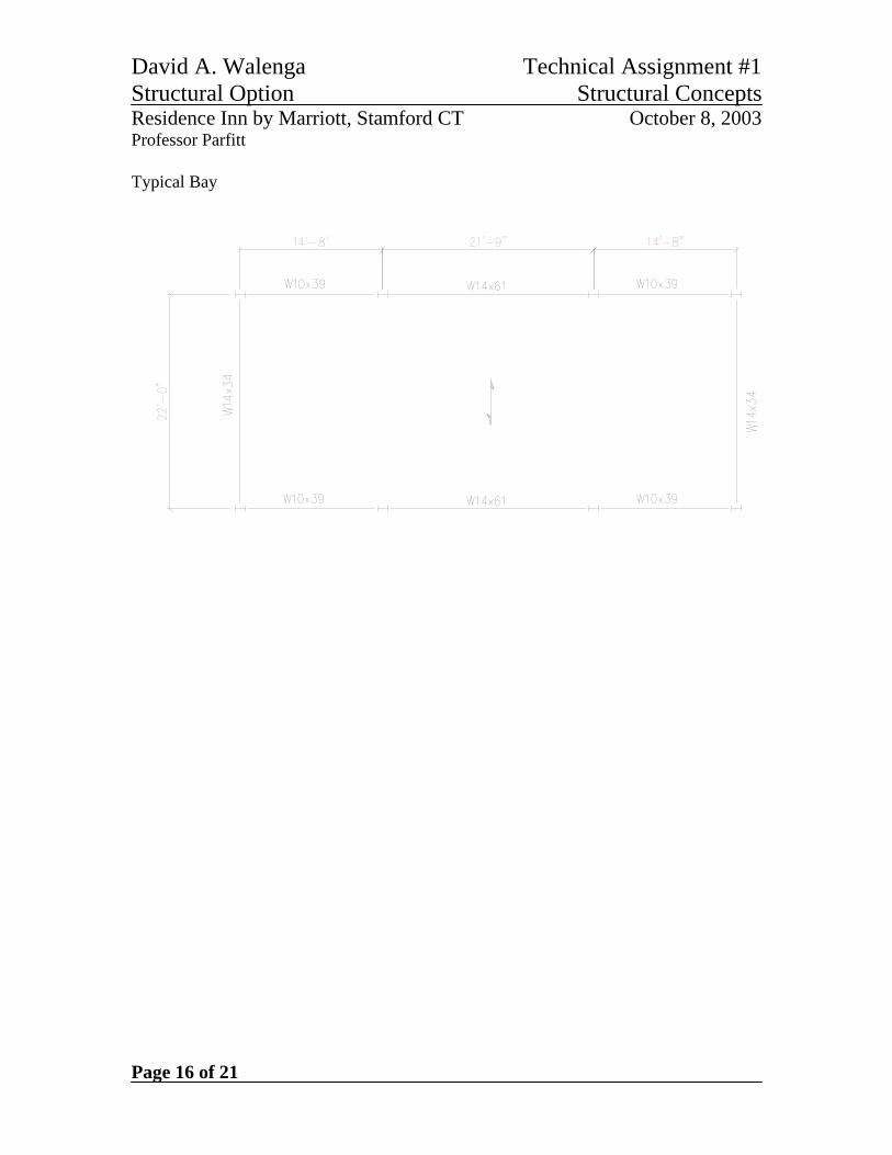
Total base shear (V) = 665 kips See Appendix D linked on Technical Assignment page for calculations. Gravity Member Check The gravity member check is accomplished using RAM Steel. A model was built of a typical bay and analyzed as if it were the ninth floor of the building. Exterior Beam in Typical Bay The design of the exterior typical beam produced a smaller member than what is shown on the drawings. The main reason for this discrepancy is due the deflection requirements assumed here compared to those assumed by the design engineer. Generally, it is desirable to limit deflection of members that support exterior cladding to protect cladding from cracking and other problems.
David A. Walenga Technical Assignment #1 Structural Option Structural Concepts Residence Inn by Marriott, Stamford CT October 8, 2003 Professor Parfitt
Page 12 of 21
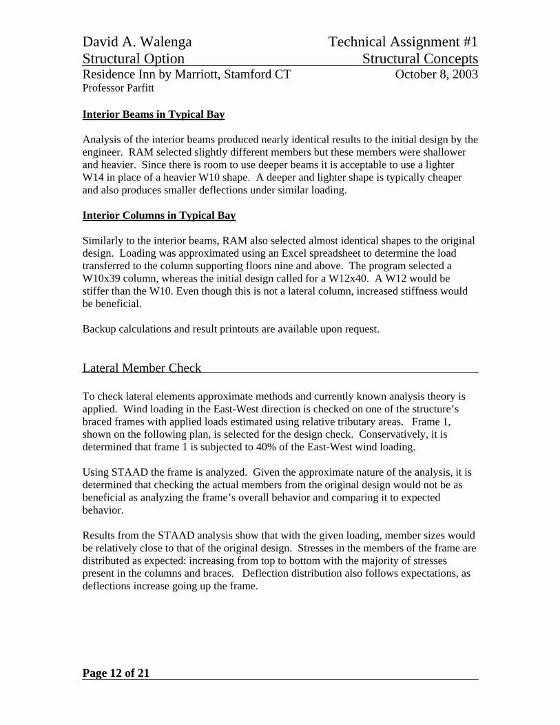
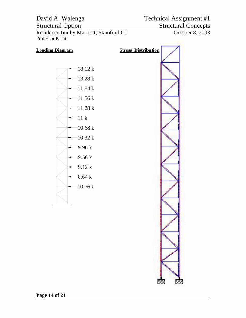
Interior Beams in Typical Bay Analysis of the interior beams produced nearly identical results to the initial design by the engineer. RAM selected slightly different members but these members were shallower and heavier. Since there is room to use deeper beams it is acceptable to use a lighter W14 in place of a heavier W10 shape. A deeper and lighter shape is typically cheaper and also produces smaller deflections under similar loading. Interior Columns in Typical Bay Similarly to the interior beams, RAM also selected almost identical shapes to the original design. Loading was approximated using an Excel spreadsheet to determine the load transferred to the column supporting floors nine and above. The program selected a W10x39 column, whereas the initial design called for a W12x40. A W12 would be stiffer than the W10. Even though this is not a lateral column, increased stiffness would be beneficial. Backup calculations and result printouts are available upon request. Lateral Member Check To check lateral elements approximate methods and currently known analysis theory is applied. Wind loading in the East-West direction is checked on one of the structure’s braced frames with applied loads estimated using relative tributary areas. Frame 1, shown on the following plan, is selected for the design check. Conservatively, it is determined that frame 1 is subjected to 40% of the East-West wind loading. Using STAAD the frame is analyzed. Given the approximate nature of the analysis, it is determined that checking the actual members from the original design would not be as beneficial as analyzing the frame’s overall behavior and comparing it to expected behavior. Results from the STAAD analysis show that with the given loading, member sizes would be relatively close to that of the original design. Stresses in the members of the frame are distributed as expected: increasing from top to bottom with the majority of stresses present in the columns and braces. Deflection distribution also follows expectations, as deflections increase going up the frame.
David A. Walenga Technical Assignment #1 Structural Option Structural Concepts Residence Inn by Marriott, Stamford CT October 8, 2003 Professor Parfitt
Page 13 of 21
1 2 3 4
5 6 7 8
N
David A. Walenga Technical Assignment #1 Structural Option Structural Concepts Residence Inn by Marriott, Stamford CT October 8, 2003 Professor Parfitt
Page 14 of 21
18.12 k
13.28 k
11.84 k
11.56 k
11 k
10.68 k
10.32 k
9.96 k
9.56 k
9.12 k
8.64 k
10.76 k
11.28 k
Loading Diagram Stress Distribution
David A. Walenga Technical Assignment #1 Structural Option Structural Concepts Residence Inn by Marriott, Stamford CT October 8, 2003 Professor Parfitt
Page 15 of 21
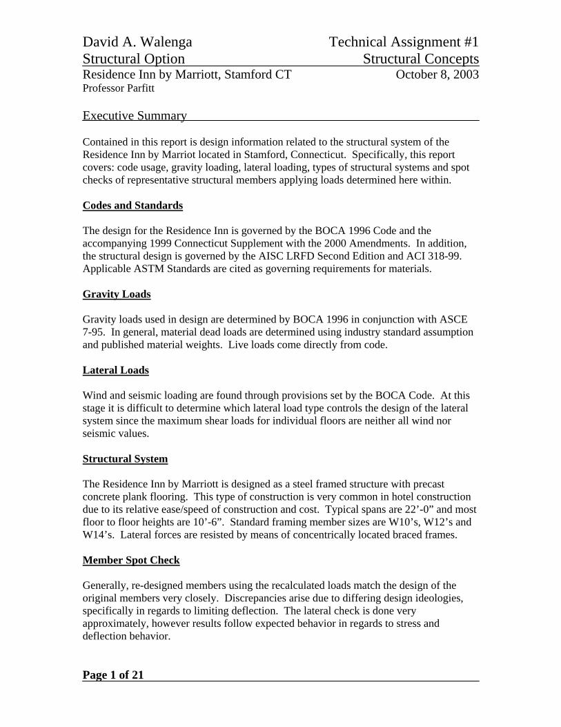
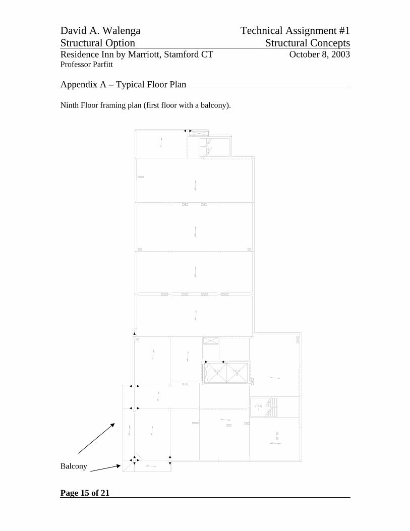
Appendix A – Typical Floor Plan Ninth Floor framing plan (first floor with a balcony). Balcony
David A. Walenga Technical Assignment #1 Structural Option Structural Concepts Residence Inn by Marriott, Stamford CT October 8, 2003 Professor Parfitt
Page 16 of 21
Typical Bay
David A. Walenga Technical Assignment #1 Structural Option Structural Concepts Residence Inn by Marriott, Stamford CT October 8, 2003 Professor Parfitt
Page 17 of 21
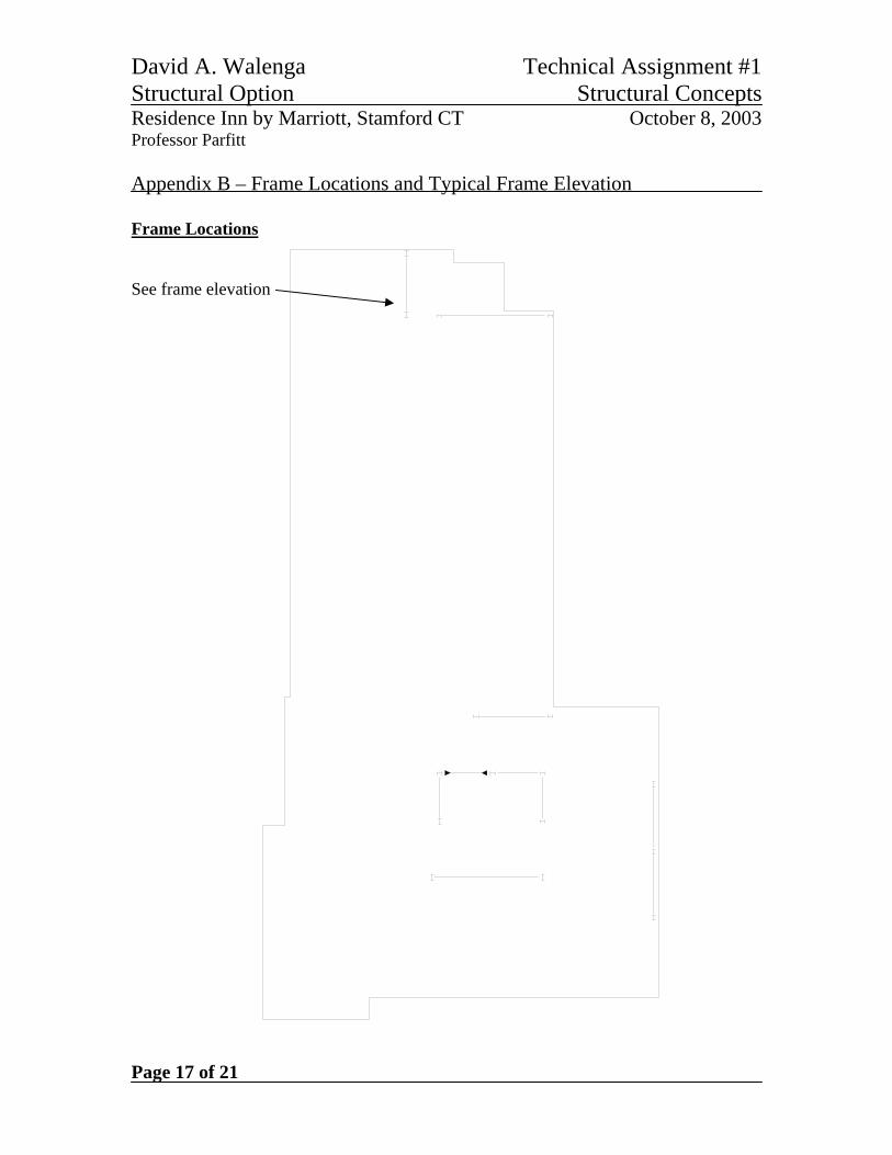
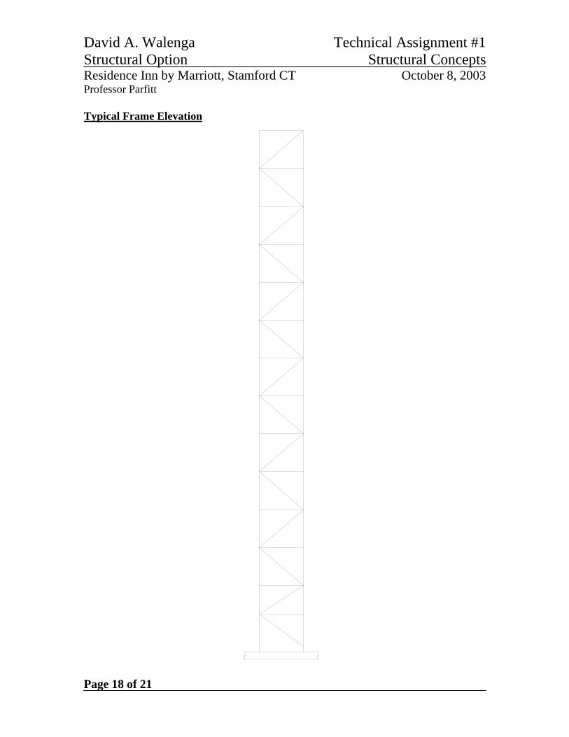
Appendix B – Frame Locations and Typical Frame Elevation Frame Locations See frame elevation
David A. Walenga Technical Assignment #1 Structural Option Structural Concepts Residence Inn by Marriott, Stamford CT October 8, 2003 Professor Parfitt
Page 18 of 21
Typical Frame Elevation
David A. Walenga Technical Assignment #1 Structural Option Structural Concepts Residence Inn by Marriott, Stamford CT October 8, 2003 Professor Parfitt
Page 19 of 21
Appendix C - Snow Loading Calculations Section 1608 Snow Loads Ground Snow Load = 30 psf Sloped roof areas= 0 Flat roof snow load = 30 psf Flat Pf,calc = CeIPg= 21 psf (For Drifting/Sloping Snow Loads Only) if < Pf,min) Pf,min = 30 psf (per Connecticut Supplement) Pf,design = 30 psf I = 1.0 Input from Table 1609.5 Pg = 30.0 psf ground snow load Ce = 0.7 Input from Table 1608.4 Sloping Ps = CsPf = NA psf For >30 degrees Cs = 1 - ((a-30)/40) a = 0 Slope in degrees
David A. Walenga Technical Assignment #1 Structural Option Structural Concepts Residence Inn by Marriott, Stamford CT October 8, 2003 Professor Parfitt
Page 20 of 21
Drifting D = 0.13(Pg) + 14 = 17.9 pcf hb = Pf /D = 1.173 ft Penthouse roof to main roof: Wb1 = 25 Input Dimension to elevation change (ft, >= 25) hd1 = 0.43Wb1
0.33(Pg + 10)0.25 - 1.5 = 1.628 ft Pm1 = D(hd1 + hb) ~ Maximum total snow loading = 50.146 psf
Width to Calculated Flat Roof
Snow Load = 4hd1 (Per Code) = 6.513 ft
Width to Minimum Flat Roof
Snow Load = 4.502 ft Average Drifted Snow Load = 40.1 psf
Main roof to dock roof: Wb2 = 126 Input Dimension to elevation change (ft, >= 25)
hd2 = 0.43Wb20.33(Pg + 10)0.25 - 1.5
= 3.835 ft Pm2 = D(hd2 + hb) ~ Maximum total snow loading = 89.64 psf
Width to Calculated Flat Roof
Snow Load = 4hd2 (Per Code) = 15.339 ft
Width to Minimum Flat Roof
Snow Load = 10.602 ft Average Drifted Snow Load = 59.8 psf
David A. Walenga Technical Assignment #1 Structural Option Structural Concepts Residence Inn by Marriott, Stamford CT October 8, 2003 Professor Parfitt
Page 21 of 21
Main roof to 6th floor roof: Wb3 = 86 Input Dimension to elevation change (ft, >= 25) hd3 = 0.43Wb3
0.33(Pg + 10)0.25 - 1.5 = 3.203 ft Pm3 = D(hd3 + hb) ~ Maximum total snow loading = 78.33 psf
Width to Calculated Flat
Roof Snow Load = 4hd3 (Per Code) = 12.81 ft
Width to Minimum Flat
Roof Snow Load = 8.856 ft
Average Drifted Snow
Load = 54.2 psf