Embed Size (px)
Citation preview
pende
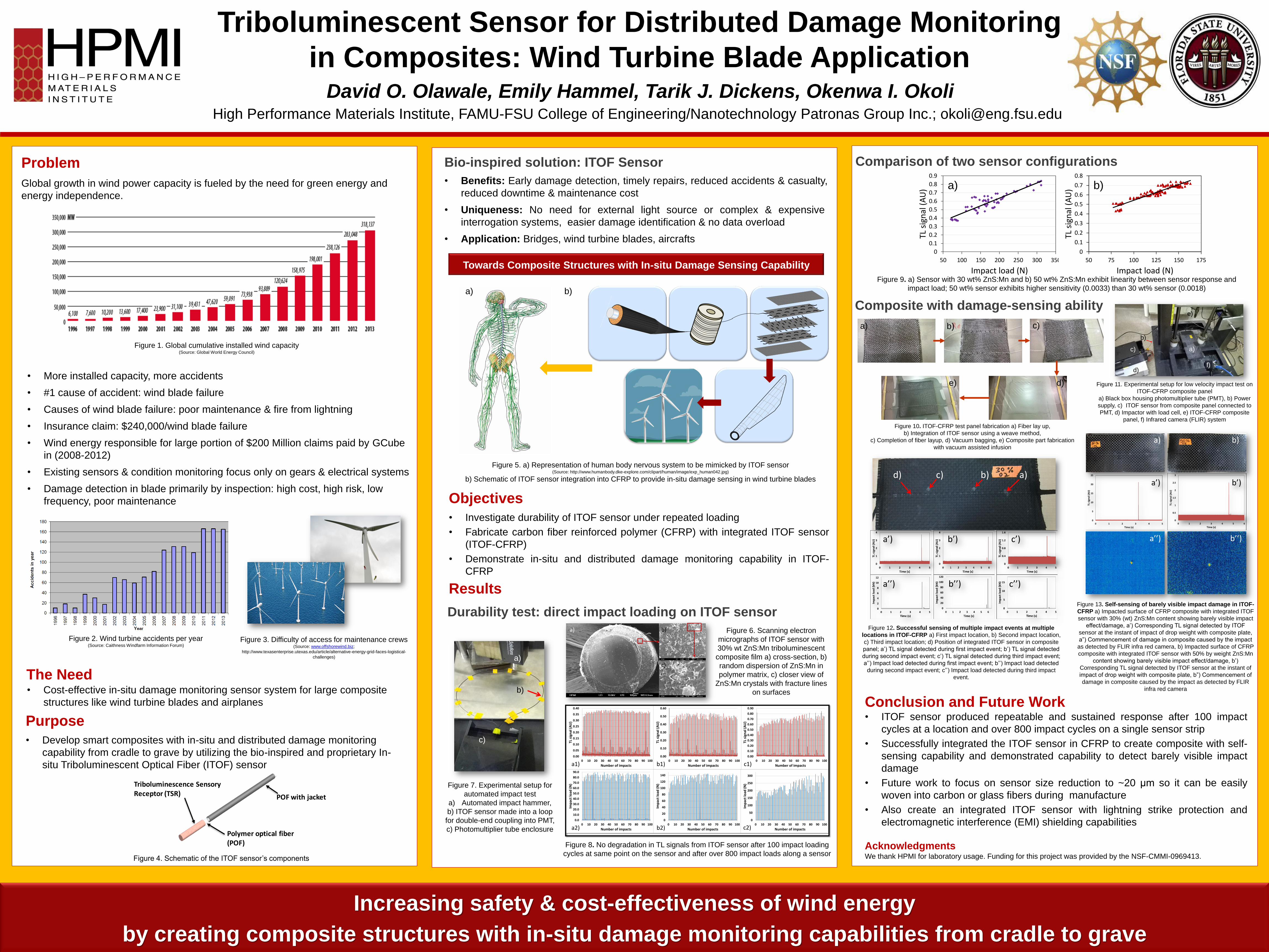
Triboluminescent Sensor for Distributed Damage Monitoring
in Composites: Wind Turbine Blade Application
Figure 8. No degradation in TL signals from ITOF sensor after 100 impact loading
cycles at same point on the sensor and after over 800 impact loads along a sensor
TiO2 coated CNT
yarn
CNT yarn
a)
Problem
Global growth in wind power capacity is fueled by the need for green energy and
energy independence.
The Need
Increasing safety & cost-effectiveness of wind energy
by creating composite structures with in-situ damage monitoring capabilities from cradle to grave
Figure 1. Global cumulative installed wind capacity (Source: Global World Energy Council)
• More installed capacity, more accidents
• #1 cause of accident: wind blade failure
• Causes of wind blade failure: poor maintenance & fire from lightning
• Insurance claim: $240,000/wind blade failure
• Wind energy responsible for large portion of $200 Million claims paid by GCube
in (2008-2012)
• Existing sensors & condition monitoring focus only on gears & electrical systems
• Damage detection in blade primarily by inspection: high cost, high risk, low
frequency, poor maintenance
Figure 2. Wind turbine accidents per year (Source: Caithness Windfarm Information Forum)
• Cost-effective in-situ damage monitoring sensor system for large composite
structures like wind turbine blades and airplanes
Objectives
• Investigate durability of ITOF sensor under repeated loading
• Fabricate carbon fiber reinforced polymer (CFRP) with integrated ITOF sensor
(ITOF-CFRP)
• Demonstrate in-situ and distributed damage monitoring capability in ITOF-
CFRP
Results
Bio-inspired solution: ITOF Sensor
• Benefits: Early damage detection, timely repairs, reduced accidents & casualty,
reduced downtime & maintenance cost
• Uniqueness: No need for external light source or complex & expensive
interrogation systems, easier damage identification & no data overload
• Application: Bridges, wind turbine blades, aircrafts
Durability test: direct impact loading on ITOF sensor
0.00
0.10
0.20
0.30
0.40
0.50
0.60
0.70
0.80
0.90
0 10 20 30 40 50 60 70 80 90 100
TL s
ign
al (
AU
)
Number of impacts
0.0
10.0
20.0
30.0
40.0
50.0
60.0
70.0
80.0
90.0
0 10 20 30 40 50 60 70 80 90 100
Imp
act
load
(N
)
Number of impacts
0.00
0.05
0.10
0.15
0.20
0.25
0.30
0.35
0.40
0 10 20 30 40 50 60 70 80 90 100
TL s
ign
al (
AU
)
Number of impacts
0.00
0.10
0.20
0.30
0.40
0.50
0.60
0 10 20 30 40 50 60 70 80 90 100
TL s
ign
al (
AU
)
Number of impacts
0
20
40
60
80
100
120
140
0 10 20 30 40 50 60 70 80 90 100
Imp
act
load
(N
)
Number of impacts
0
50
100
150
200
250
300
0 10 20 30 40 50 60 70 80 90 100
Imp
act
load
(N
)
Number of impacts
a1)
a2)
b1)
b2) c2)
c1)
a)b)c)d)
a’)
a’’)
b’) c’)
b’’) c’’)
a)
d)
e)
b)
c)
f)
a)
a’)
a’’)
b)
b’)
b’’)
a) b)
c)
Figure 6. Scanning electron
micrographs of ITOF sensor with
30% wt ZnS:Mn triboluminescent
composite film a) cross-section, b)
random dispersion of ZnS:Mn in
polymer matrix, c) closer view of
ZnS:Mn crystals with fracture lines
on surfaces
0
0.1
0.2
0.3
0.4
0.5
0.6
0.7
0.8
0.9
50 100 150 200 250 300 350
TL s
ign
al (
AU
)
Impact load (N)
0
0.1
0.2
0.3
0.4
0.5
0.6
0.7
0.8
50 75 100 125 150 175
TL s
ign
al (
AU
)
Impact load (N)
a) b)
Figure 9. a) Sensor with 30 wt% ZnS:Mn and b) 50 wt% ZnS:Mn exhibit linearity between sensor response and
impact load; 50 wt% sensor exhibits higher sensitivity (0.0033) than 30 wt% sensor (0.0018)
Comparison of two sensor configurations
Composite with damage-sensing ability
Figure 10. ITOF-CFRP test panel fabrication a) Fiber lay up,
b) Integration of ITOF sensor using a weave method,
c) Completion of fiber layup, d) Vacuum bagging, e) Composite part fabrication
with vacuum assisted infusion
Figure 11. Experimental setup for low velocity impact test on
ITOF-CFRP composite panel
a) Black box housing photomultiplier tube (PMT), b) Power
supply, c) ITOF sensor from composite panel connected to
PMT, d) Impactor with load cell, e) ITOF-CFRP composite
panel, f) Infrared camera (FLIR) system
Figure 12. Successful sensing of multiple impact events at multiple
locations in ITOF-CFRP a) First impact location, b) Second impact location,
c) Third impact location; d) Position of integrated ITOF sensor in composite
panel; a’) TL signal detected during first impact event; b’) TL signal detected
during second impact event; c’) TL signal detected during third impact event;
a’’) Impact load detected during first impact event; b’’) Impact load detected
during second impact event; c’’) Impact load detected during third impact
event.
Conclusion and Future Work • ITOF sensor produced repeatable and sustained response after 100 impact
cycles at a location and over 800 impact cycles on a single sensor strip
• Successfully integrated the ITOF sensor in CFRP to create composite with self-
sensing capability and demonstrated capability to detect barely visible impact
damage
• Future work to focus on sensor size reduction to ~20 μm so it can be easily
woven into carbon or glass fibers during manufacture
• Also create an integrated ITOF sensor with lightning strike protection and
electromagnetic interference (EMI) shielding capabilities
Acknowledgments We thank HPMI for laboratory usage. Funding for this project was provided by the NSF-CMMI-0969413.
Figure 13. Self-sensing of barely visible impact damage in ITOF-
CFRP a) Impacted surface of CFRP composite with integrated ITOF
sensor with 30% (wt) ZnS:Mn content showing barely visible impact
effect/damage, a’) Corresponding TL signal detected by ITOF
sensor at the instant of impact of drop weight with composite plate,
a”) Commencement of damage in composite caused by the impact
as detected by FLIR infra red camera, b) Impacted surface of CFRP
composite with integrated ITOF sensor with 50% by weight ZnS:Mn
content showing barely visible impact effect/damage, b’)
Corresponding TL signal detected by ITOF sensor at the instant of
impact of drop weight with composite plate, b”) Commencement of
damage in composite caused by the impact as detected by FLIR
infra red camera
Figure 3. Difficulty of access for maintenance crews (Source: www.offshorewind.biz;
http://www.texasenterprise.utexas.edu/article/alternative-energy-grid-faces-logistical-
challenges)
David O. Olawale, Emily Hammel, Tarik J. Dickens, Okenwa I. Okoli High Performance Materials Institute, FAMU-FSU College of Engineering/Nanotechnology Patronas Group Inc.; [email protected]
Figure 5. a) Representation of human body nervous system to be mimicked by ITOF sensor (Source: http://www.humanbody.dke-explore.com/clipart/human/image/exp_human042.jpg)
b) Schematic of ITOF sensor integration into CFRP to provide in-situ damage sensing in wind turbine blades
a)
c)
b)
Triboluminescence Sensory Receptor (TSR)
Polymer optical fiber (POF)
POF with jacket
Figure 7. Experimental setup for
automated impact test
a) Automated impact hammer,
b) ITOF sensor made into a loop
for double-end coupling into PMT,
c) Photomultiplier tube enclosure
Purpose
• Develop smart composites with in-situ and distributed damage monitoring
capability from cradle to grave by utilizing the bio-inspired and proprietary In-
situ Triboluminescent Optical Fiber (ITOF) sensor
a) b)
Towards Composite Structures with In-situ Damage Sensing Capability
Figure 4. Schematic of the ITOF sensor’s components
a) b) c)
d)e)